EP3605247A1 - Disturbance non-interference-enabling compensation system for positioning control device, and component mounting apparatus - Google Patents
Disturbance non-interference-enabling compensation system for positioning control device, and component mounting apparatus Download PDFInfo
- Publication number
- EP3605247A1 EP3605247A1 EP17904300.5A EP17904300A EP3605247A1 EP 3605247 A1 EP3605247 A1 EP 3605247A1 EP 17904300 A EP17904300 A EP 17904300A EP 3605247 A1 EP3605247 A1 EP 3605247A1
- Authority
- EP
- European Patent Office
- Prior art keywords
- disturbance
- interference
- moving body
- output
- enabling
- Prior art date
- Legal status (The legal status is an assumption and is not a legal conclusion. Google has not performed a legal analysis and makes no representation as to the accuracy of the status listed.)
- Granted
Links
Images


Classifications
-
- H—ELECTRICITY
- H05—ELECTRIC TECHNIQUES NOT OTHERWISE PROVIDED FOR
- H05K—PRINTED CIRCUITS; CASINGS OR CONSTRUCTIONAL DETAILS OF ELECTRIC APPARATUS; MANUFACTURE OF ASSEMBLAGES OF ELECTRICAL COMPONENTS
- H05K13/00—Apparatus or processes specially adapted for manufacturing or adjusting assemblages of electric components
- H05K13/08—Monitoring manufacture of assemblages
- H05K13/0882—Control systems for mounting machines or assembly lines, e.g. centralized control, remote links, programming of apparatus and processes as such
-
- G—PHYSICS
- G05—CONTROLLING; REGULATING
- G05B—CONTROL OR REGULATING SYSTEMS IN GENERAL; FUNCTIONAL ELEMENTS OF SUCH SYSTEMS; MONITORING OR TESTING ARRANGEMENTS FOR SUCH SYSTEMS OR ELEMENTS
- G05B13/00—Adaptive control systems, i.e. systems automatically adjusting themselves to have a performance which is optimum according to some preassigned criterion
- G05B13/02—Adaptive control systems, i.e. systems automatically adjusting themselves to have a performance which is optimum according to some preassigned criterion electric
- G05B13/0205—Adaptive control systems, i.e. systems automatically adjusting themselves to have a performance which is optimum according to some preassigned criterion electric not using a model or a simulator of the controlled system
- G05B13/024—Adaptive control systems, i.e. systems automatically adjusting themselves to have a performance which is optimum according to some preassigned criterion electric not using a model or a simulator of the controlled system in which a parameter or coefficient is automatically adjusted to optimise the performance
-
- G—PHYSICS
- G05—CONTROLLING; REGULATING
- G05B—CONTROL OR REGULATING SYSTEMS IN GENERAL; FUNCTIONAL ELEMENTS OF SUCH SYSTEMS; MONITORING OR TESTING ARRANGEMENTS FOR SUCH SYSTEMS OR ELEMENTS
- G05B11/00—Automatic controllers
- G05B11/01—Automatic controllers electric
- G05B11/32—Automatic controllers electric with inputs from more than one sensing element; with outputs to more than one correcting element
-
- G—PHYSICS
- G05—CONTROLLING; REGULATING
- G05B—CONTROL OR REGULATING SYSTEMS IN GENERAL; FUNCTIONAL ELEMENTS OF SUCH SYSTEMS; MONITORING OR TESTING ARRANGEMENTS FOR SUCH SYSTEMS OR ELEMENTS
- G05B19/00—Program-control systems
- G05B19/02—Program-control systems electric
- G05B19/18—Numerical control [NC], i.e. automatically operating machines, in particular machine tools, e.g. in a manufacturing environment, so as to execute positioning, movement or co-ordinated operations by means of program data in numerical form
- G05B19/4155—Numerical control [NC], i.e. automatically operating machines, in particular machine tools, e.g. in a manufacturing environment, so as to execute positioning, movement or co-ordinated operations by means of program data in numerical form characterised by program execution, i.e. part program or machine function execution, e.g. selection of a program
-
- H—ELECTRICITY
- H05—ELECTRIC TECHNIQUES NOT OTHERWISE PROVIDED FOR
- H05K—PRINTED CIRCUITS; CASINGS OR CONSTRUCTIONAL DETAILS OF ELECTRIC APPARATUS; MANUFACTURE OF ASSEMBLAGES OF ELECTRICAL COMPONENTS
- H05K13/00—Apparatus or processes specially adapted for manufacturing or adjusting assemblages of electric components
- H05K13/04—Mounting of components, e.g. of leadless components
-
- G—PHYSICS
- G05—CONTROLLING; REGULATING
- G05B—CONTROL OR REGULATING SYSTEMS IN GENERAL; FUNCTIONAL ELEMENTS OF SUCH SYSTEMS; MONITORING OR TESTING ARRANGEMENTS FOR SUCH SYSTEMS OR ELEMENTS
- G05B2219/00—Program-control systems
- G05B2219/30—Nc systems
- G05B2219/39—Robotics, robotics to robotics hand
- G05B2219/39421—DOF is degree of freedom, 2-DOF
Definitions
- the present specification discloses technology related to a disturbance non-interference-enabling compensation system for positioning control device and a component mounting apparatus for controlling the position of moving bodies in a moving body driving system in which multiple moving bodies individually driven by multiple driving sources are mounted on a single machine base or multiple coupled machine bases, and disturbances generated by the acceleration and deceleration driving of any of the moving bodies are transmitted to adjacent moving bodies via the machine base.
- a modular component mounting line described in patent literature 1 JP-A-2004-104075
- the modular component mounting line has a configuration in which multiple mounter modules are connected to each other, and two moving bodies (Y slides) for moving two mounting heads are mounted on each mounter module.
- the disturbance non-interference-enabling compensation device of patent literature 2 includes an observation means for observing (detecting) the position of a moving object, a disturbance non-interference-enabling compensator for performing non-interference-enabling compensation of the disturbance with respect to the observation amount of the moving object on the disturbance influenced side, and the disturbance non-interference-enabling compensator is configured to include: a first feedforward compensator for outputting a feedforward compensation amount for performing non-interference-enabling compensation of the disturbance with respect to the control amount of the moving object on the disturbance influenced side using the operation amount of the moving object on the disturbance generating side as an input; a second feedforward compensator for outputting a target command correction amount using the operation amount of the moving object on the disturbance generating side as an input; a first calculator for correcting the operation amount of the moving object on the disturbance influenced side using the output of the first feedforward compensator;
- the disturbance non-interference-enabling compensation device of patent literature 2 described above performs non-interference-enabling compensation of disturbance based on the operation amount of the moving body on the disturbance generating side, but since the operation amount of the moving body on the disturbance generating side includes the feedback compensation amount for a mechanical characteristic such as frictional force by normal feedback control, there is a problem that the compensation amount for performing non-interference-enabling compensation of the disturbance is liable to be affected by the mechanical characteristic of the moving body on the disturbance generating side.
- the operation amount of the moving body on the disturbance generating side includes the feedback compensation amount for the mechanical characteristics such as the frictional force described above and also includes a control delay due to feedback control, even if the feedforward compensation amount for performing the non-interference-enabling compensation of the disturbance is output from the operation amount, there is a problem that a desired compensation result cannot be obtained.
- the feedforward compensator when a feedforward compensator for non-interference-enabling is constructed in consideration of an inverse characteristic of a nominal model of a transmission characteristic from the operation amount of the moving body on the side subject to the influence of the disturbance to the control amount, the feedforward compensator includes a second-order differential characteristic. As a result, the feedforward compensation amount has a fourth derivative of the position command value as a component.
- the operation amount (torque) is equivalent to the second derivative of the position command value multiplied by the inertia of the control object, and further multiplied by the inverse characteristic (characteristic including the second derivative) of the nominal model of the transmission characteristic from the operation amount to the control amount, so the fourth derivative of the position command value is consequently included as a component.
- the physical meaning of the feed forward compensation amount becomes unknown, and it is difficult to adjust the feed forward compensation amount.
- the configuration of the disturbance non-interference-enabling compensator becomes complicated, and the positioning control software with the disturbance non-interference-enabling compensator becomes complicated, resulting in a problem that the calculation load of the CPU becomes large.
- a disturbance non-interference-enabling compensation system of a positioning control device for controlling the position of moving bodies by a two-degree-of-freedom control system in a moving body drive system in which multiple moving bodies individually accelerated and decelerated by multiple drive sources are mounted on a single machine base or multiple connected machine bases, and disturbances generated by acceleration and deceleration driving of any of the moving bodies are transmitted to an adjacent another of the moving bodies via the machine base,
- the system including: a two-degree-of-freedom control system, the two-degree-of-freedom control system including: a detecting section configured to detect the position of the moving body; a feedback compensator configured to output a feedback operation amount such that a deviation between a position command value of the moving body and a detection value of the detecting section is input, the feedback operation amount being output such that the deviation is small; a feedforward compensator configured to output a feedforward operation amount using the position command value of the moving body as an input; an adder configured to output the operation amount of
- the moving body on the disturbance-receiving side has a characteristic that the influence of the disturbance increases as the absolute value of the acceleration (deceleration) of the moving body on the disturbance-generating side increases. Focusing on this characteristic, the position command value of the moving body on the disturbance-generating side is differentiated to the second order to obtain an acceleration command value, and this acceleration command value is multiplied by a predetermined gain to obtain a correction amount with respect to the input of the feedback compensator of the moving body on the disturbance-receiving side and a correction amount with respect to the operation amount, thereby performing the non-interference-enabling compensation of the disturbance.
- control system for controlling the position of each moving body is not limited to a two-degree-of-freedom control system (combination of feedback control and feedforward control), but may be a one-degree-of-freedom control system based only on feedback control.
- the present invention may be applied to a moving body driving system that accelerates and decelerates multiple moving bodies in the same direction or in the opposite direction. Since the acceleration command value obtained by second-order differentiation of the position command value depends on the moving direction of the moving body, when the moving direction of the moving body is different, the first gain and the second gain may be changed according to the moving direction of the moving object in consideration of the fact that the degree of influence of the disturbance is different depending on the moving direction of the moving object.
- the magnitude of the disturbance transmitted to the moving body changes in accordance with the position of the moving body on the disturbance-generating side, the position of the moving body on the disturbance-receiving side, or the distance between both.
- at least one of the first gain and the second gain may be changed in accordance with at least one of a position of the moving body on the disturbance-generating side and a position of the moving body on the disturbance-receiving side.
- at least one of the first gain and the second gain may be changed in accordance with a distance between the moving body on the disturbance-generating side and the moving body on the disturbance-receiving side.
- the present disclosure is not limited to only one moving body on the disturbance-generating side, and is also applicable to a moving body driving system in which there are multiple moving bodies on the disturbance-generating side and multiple disturbances generated by acceleration and deceleration driving of the multiple moving bodies on the disturbance generating-side are transmitted to one moving body.
- the second-order differentiator, the first multiplier, and the second multiplier may be provided for each of the multiple disturbance-generating side moving bodies, and the non-interference-enabling compensation of the disturbance may be performed by correcting the operation amount and the input of the feedback compensator of the moving body on the disturbance-receiving side using a sum of outputs of the multiple first multipliers and a sum of outputs of the multiple second multipliers.
- a first embodiment will be described with reference to figs. 1 to 3 .
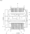
- First, the configuration of component mounting apparatus 11 will be described with reference to fig 1 .
- Conveyor 14 for conveying circuit board 13 in the X direction is provided on a center side of machine base 12 of component mounting apparatus 11, and component supply devices 15 and 16 for supplying components are provided on both sides of machine base 12 in the Y direction (a direction orthogonal to the X direction).
- Two Y slide bases 17 and 18 are provided in parallel along the Y direction on both sides of machine base 12 in the X direction, and two Y slides 19 and 20 (moving bodies) moving in the Y direction are provided on the two Y slide bases 17 and 18.
- Y slides 19 and 20 are respectively provided with mounting heads 21 and 22 via X slides (not shown), and one or multiple suction nozzles (not shown) are respectively held on mounting heads 21 and 22, and components supplied from the component supply devices 15 and 16 are picked up by the suction nozzles and mounted on circuit board 13.
- Y slides 19 and 20 are respectively provided with drive sources 23 and 24 such as a ball screw drive device or a linear motor drive device, and Y slides 19 and 20 are individually accelerated and decelerated in the Y direction by drive sources 23 and 24.
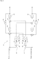
- positioning control circuit 31 for individually controlling the positions (Y coordinates) of the two Y slides 19 and 20 will be described with reference to fig. 2 .
- Positioning control circuit 31 of the first embodiment is configured from a two-degree-of-freedom control system in which feedback control and feedforward control are combined.
- feedback may be referred to as “F/B”
- feedforward may be referred to as "F/F”.
- the positions of the Y slides 19 and 20 are detected by detectors 32 and 33 such as encoders or linear scales (also known as linear encoders).
- the detection characteristics of detecting sections 32 and 33 are represented by transmission variables H1 and H2, respectively.
- the two-degree-of-freedom control system for individually controlling the position of each Y slide 19, 20 includes feedback compensators 34, 35 (transmitting functions C1, C2) configured to receive the deviation between the position command values 1, 2 of each Y slide 19, 20 and the detection values of detecting sections 32, 33 and output the feedback operation amount such that the deviation is small, feedforward compensators 36, 37 (transmission functions FF1, FF2) configured to receive the position command values 1, 2 of each Y slide 19, 20 and output the feedforward operation amount, and adders 38, 39 configured to add the feedback operation amount and the feedforward operation amount and output the operation amount of each Y slide 19, 20, and driving sources 23, 24 (transmission variables P1, P2) of each Y slide 19, 20 that are targets for control are controlled by the outputs (operation amounts) of each add
- the two-degree-of-freedom control system for individually controlling the positions of Y slides 19 and 20 includes disturbance non-interference-enabling compensators 41 and 42 configured to perform non-interference-enabling compensation of the disturbance with respect to the inputs and the operation amounts of feedback compensators 34 and 35 of Y slides 19 and 20 on the side affected by the disturbance generated by the acceleration and deceleration driving of the Y slide on the respective opposite side.
- disturbance non-interference-enabling compensator 41 for non-interference-enabling compensation of the disturbance includes: second-order differentiator 43 configured to perform second-order differentiation of the position command value of Y slide 19 on a disturbance-generating side and output an acceleration command value, a first multiplier configured to multiply the acceleration command value that is an output of second-order differentiator 43 by a first gain (Kp1) and output a correction amount with respect to the input of the feedback compensator 35 on the Y slide 20 on the disturbance-receiving side, and second multiplier 47 configured to multiply the acceleration command value that is the output of the second-order differentiator by a second gain (Kt1) and output a correction amount with respect to the operation amount of the Y slide 20 on the disturbance-receiving side, and the disturbance non-interference-enabling compensation system of the positioning control device performs the disturbance non-interference-enabling compensation by correcting the operation amount and the input of
- adder 50 configured to add the output of second multiplier 47 to the operation amount that is the output of adder 39 of Y slide 20 on the disturbance-receiving side is provided to correct the operation amount, but adder 50 may be omitted and the output of second multiplier 47 may be input to adder 39 to correct the operation amount.
- disturbance non-interference-enabling compensator 42 for non-interference-enabling compensation of the disturbance includes: second-order differentiator 44 configured to perform second-order differentiation of the position command value of Y slide 20 on a disturbance-generating side and output an acceleration command value, first multiplier 46 configured to multiply the acceleration command value that is an output of second-order differentiator 44 by a first gain (Kp2) and output a correction amount with respect to the input of the feedback compensator 34 on the Y slide 19 on the disturbance-receiving side, and second multiplier 48 configured to multiply the acceleration command value that is the output of the second-order differentiator by a second gain (Kt2) and output a correction amount with respect to the operation amount of the Y slide 19 on the disturbance-receiving side, and the disturbance non-interference-enabling compensation system of the positioning control device performs the disturbance non-interference-enabling compensation by correcting the operation amount and the input
- adder 49 configured to add the output of second multiplier 48 to the operation amount that is the output of adder 38 of Y slide 19 on the disturbance-receiving side is provided to correct the operation amount, but adder 49 may be omitted and the output of second multiplier 48 may be input to adder 38 to correct the operation amount.
- the Y slide on the disturbance-receiving side has a characteristic that the influence of the disturbance increases as the absolute value of the acceleration (deceleration) of the Y slide on the disturbance-generating side increases. Focusing on this characteristic, in the first embodiment, the position command value of the Y slide on the disturbance-generating side is differentiated to the second order to obtain an acceleration command value, and this acceleration command value is multiplied by a predetermined gain (first gain and second gain) to obtain a correction amount with respect to the input of the feedback compensator of the Y slide on the disturbance-receiving side and a correction amount with respect to the operation amount, thereby performing the non-interference-enabling compensation of the disturbance.
- a predetermined gain first gain and second gain
- the magnitude of the disturbance transmitted to the Y slide changes in accordance with the position of the Y slide on the disturbance-generating side, the position of the Y slide on the disturbance-receiving side, or the distance between both.
- at least one of the first gain and the second gain may be changed in accordance with at least one of a position of the Y slide on the disturbance-generating side and a position of the Y slide on the disturbance-receiving side.
- at least one of the first gain and the second gain may be changed in accordance with a distance between the Y slide on the disturbance-generating side and the Y slide on the disturbance-receiving side.
- the first gain and the second gain may be fixed values set in advance.
- Fig. 3 shows a comparison between the acceleration command value obtained by second-order differential of the position command value of the Y slide on the disturbance-generating side (output of the second-order differentiator), the relative displacement when the disturbance non-interference-enabling compensation of the first embodiment is performed, and the relative displacement of a comparative example in which the disturbance non-interference-enabling compensation is not performed.
- the relative displacement in a case where the disturbance non-interference-enabling compensation is performed in the first embodiment is reduced by half compared to the relative displacement in a comparative example in which the disturbance non-interference-enabling compensation is not performed. Therefore, with the first embodiment, even if the two Y slides 19 and 20 are simultaneously driven, it is possible to prevent deterioration of the component mounting accuracy and lowering of the component pickup rate due to the disturbance generated by the acceleration and deceleration driving of the Y slide on the disturbance-generating side.
- the effect of the disturbance non-interference compensation eliminates the need to increase the rigidity of machine base 12, the Y slide bases 17, 18, and the like of component mounting apparatus 11 more than necessary, and component mounting apparatus 11 can be reduced in weight.
- the disturbance non-interference-enabling compensators 41 and 42 of the first embodiment described above calculate the acceleration command value by second-order differentiation of the position command value of the Y slide on the disturbance-generating side, and multiply this acceleration command value by a predetermined gain (first gain and second gain) to calculate the correction amount for the input of the feedback compensator of the Y slide on the side affected by the disturbance and the correction amount for the operation amount, and thereby perform the non-interference-enabling compensation of the disturbance, it is possible to solve the problem caused by performing the non-interference-enabling compensation of the disturbance based on the operation amount of the moving object on the disturbance-generating side, as in patent literature 2 described above.
- the disturbance non-interference-enabling compensators 41 and 42 of the first embodiment do not use the feedback compensation amount for a mechanical characteristic such as frictional force of the Y slide on the disturbance-generating side, the compensation amount for non-interference-enabling of the disturbance is hardly affected by the mechanical characteristic of the Y slide on the disturbance-generating side.
- a control delay by feedback control is not included, it is possible to accurately calculate the compensation amount for non-interference-enabling of the disturbance while waiting for the influence of the mechanical characteristic of the Y slide on the disturbance-generating side described above, and it is possible to increase the effect of the non-interference-enabling compensation of the disturbance as compared with the above-described patent literature 2.
- the disturbance non-interference-enabling compensators 41 and 42 of the first embodiment have a simple configuration in which the position command value of the Y slide on the disturbance-generating side is only second-order differentiated and multiplied by the gain, it is possible to simplify the positioning control software of the two-degree-of-freedom control system with the disturbance non-interference-enabling compensators 41 and 42, and it is possible to reduce the calculation load of the CPU. Moreover, since the disturbance non-interference-enabling compensators 41 and 42 of the first embodiment only include the second derivative of the position command value and do not include the fourth derivative, there is an advantage that the adjustment is easy.
- positioning control circuit 31 for individually controlling the positions of the two Y slides 19 and 20 is configured by a two-degree-of-freedom control system (a combination of feedback control and feedforward control), but in a second embodiment, positioning control circuit 51 for individually controlling the positions of the two Y slides 19 and 20 is constituted by a one-degree-of-freedom control system using only feedback control.
- the one-degree-of-freedom control system that individually controls the positions of Y slides 19 and 20 includes disturbance non-interference-enabling compensators 41 and 42 that perform non-interference-enabling compensation of the disturbance with respect to the input and the operation amount of the feedback compensator of the Y slide on the side affected by the disturbance generated by the acceleration and deceleration driving of the Y slide on the respective opposite sides.
- the configuration of each of the disturbance non-interference-enabling compensators 41 and 42 is the same as that of the first embodiment.
- the non-interference compensation of disturbance is performed between two Y slides 19 and 20 provided on machine base 12 of one component mounting apparatus 11, but only one Y slide may be provided on the machine base of one component mounting apparatus, and multiple component mounting machines may be connected, with disturbance generated by the acceleration and deceleration driving of the Y slide of an adjacent component mounting apparatus being transmitted to the Y slide of another adjacent component mounting apparatus via the machine base.
- similar non-interference-enabling compensation of disturbance as in embodiments 1 and 2 may be performed between the Y slides of two adjacent component mounting machines.
- a third embodiment there are multiple Y slides on the disturbance generating side, and multiple disturbances generated by acceleration and deceleration driving of the multiple Y slides on the disturbance generating side are transmitted to one Y slide.
- two Y slides 19 and 20 are provided on the machine base 12 of one component mounting apparatus 11, and multiple component mounting apparatuses 11 are connected to each other, so that disturbance generated by acceleration and deceleration driving of Y slides 19 and 20 of adjacent component mounting apparatuses 11 may be transmitted to Y slides 19 and 20 of an adjacent component mounting apparatus 11 via machine base 12.
- a second-order differentiator, a first multiplier, and a second multiplier similar to those in the first and second embodiments may be provided for each of the Y slides on the disturbance generating side, and the input and the operation amount of the feedback compensator on the Y slide on the side affected by the disturbance may be corrected by the sum of the outputs of the multiple first multiplications and the sum of the outputs of the multiple second multipliers of the Y slides on the disturbance generating side to perform the non-interference-enabling compensation of the disturbance.
- the Y slide drive system is used as a moving body drive system for accelerating and decelerating multiple moving bodies in the same direction or in the opposite direction, but the present invention may be applied to a moving body drive system for accelerating and decelerating multiple moving bodies other than a Y slide in the same direction or in the opposite direction. Since the acceleration command value obtained by second-order differentiation of the position command value depends on the moving direction of the moving body, if the present invention is applied to a moving body driving system that accelerates and decelerates multiple moving bodies in the same direction or in the opposite direction, it is possible to perform non-interference-enabling compensation of disturbance, as in the first to third embodiments.
- the first gain and the second gain may be changed in accordance with the moving direction of the moving body in consideration of the fact that the degree of influence of disturbance is different depending on the moving direction of the moving body.
- the present invention is not limited to the above-mentioned first to third embodiments, and it is needless to say that the present invention can be implemented by various modifications within a range not deviating from the gist, such as being applicable to each device of a machine tool or a production line other than a component mounting apparatus, for example.
Landscapes
- Engineering & Computer Science (AREA)
- Manufacturing & Machinery (AREA)
- Automation & Control Theory (AREA)
- Microelectronics & Electronic Packaging (AREA)
- Physics & Mathematics (AREA)
- General Physics & Mathematics (AREA)
- Human Computer Interaction (AREA)
- Operations Research (AREA)
- Artificial Intelligence (AREA)
- Software Systems (AREA)
- Medical Informatics (AREA)
- Evolutionary Computation (AREA)
- Computer Vision & Pattern Recognition (AREA)
- Health & Medical Sciences (AREA)
- Control Of Position Or Direction (AREA)
- Supply And Installment Of Electrical Components (AREA)
- Feedback Control In General (AREA)
Abstract
Description
- The present specification discloses technology related to a disturbance non-interference-enabling compensation system for positioning control device and a component mounting apparatus for controlling the position of moving bodies in a moving body driving system in which multiple moving bodies individually driven by multiple driving sources are mounted on a single machine base or multiple coupled machine bases, and disturbances generated by the acceleration and deceleration driving of any of the moving bodies are transmitted to adjacent moving bodies via the machine base.
- As a moving body driving system in which multiple moving bodies that are individually accelerated and decelerated by multiple driving sources are mounted on a single machine base or multiple coupled machine bases, for example, a modular component mounting line described in patent literature 1 (
JP-A-2004-104075 - A disturbance non-interference-enabling compensation device that solves such a problem only by changing or adding software is disclosed in patent literature 2 (Japanese patent
5382777 patent literature 2 includes an observation means for observing (detecting) the position of a moving object, a disturbance non-interference-enabling compensator for performing non-interference-enabling compensation of the disturbance with respect to the observation amount of the moving object on the disturbance influenced side, and the disturbance non-interference-enabling compensator is configured to include: a first feedforward compensator for outputting a feedforward compensation amount for performing non-interference-enabling compensation of the disturbance with respect to the control amount of the moving object on the disturbance influenced side using the operation amount of the moving object on the disturbance generating side as an input; a second feedforward compensator for outputting a target command correction amount using the operation amount of the moving object on the disturbance generating side as an input; a first calculator for correcting the operation amount of the moving object on the disturbance influenced side using the output of the first feedforward compensator; and a second calculator for correcting the target command of the moving object on the disturbance influenced side using the output of the second feedforward compensator. -
- Patent literature 1:
JP-2004-104075 - Patent literature 2: Japanese patent number
5382777 - The disturbance non-interference-enabling compensation device of
patent literature 2 described above performs non-interference-enabling compensation of disturbance based on the operation amount of the moving body on the disturbance generating side, but since the operation amount of the moving body on the disturbance generating side includes the feedback compensation amount for a mechanical characteristic such as frictional force by normal feedback control, there is a problem that the compensation amount for performing non-interference-enabling compensation of the disturbance is liable to be affected by the mechanical characteristic of the moving body on the disturbance generating side. - Further, since the operation amount of the moving body on the disturbance generating side includes the feedback compensation amount for the mechanical characteristics such as the frictional force described above and also includes a control delay due to feedback control, even if the feedforward compensation amount for performing the non-interference-enabling compensation of the disturbance is output from the operation amount, there is a problem that a desired compensation result cannot be obtained.
- Further, as described in
claims 2 and 3 ofpatent literature 2, when a feedforward compensator for non-interference-enabling is constructed in consideration of an inverse characteristic of a nominal model of a transmission characteristic from the operation amount of the moving body on the side subject to the influence of the disturbance to the control amount, the feedforward compensator includes a second-order differential characteristic. As a result, the feedforward compensation amount has a fourth derivative of the position command value as a component. Thus, the operation amount (torque) is equivalent to the second derivative of the position command value multiplied by the inertia of the control object, and further multiplied by the inverse characteristic (characteristic including the second derivative) of the nominal model of the transmission characteristic from the operation amount to the control amount, so the fourth derivative of the position command value is consequently included as a component. For this reason, the physical meaning of the feed forward compensation amount becomes unknown, and it is difficult to adjust the feed forward compensation amount. Moreover, the configuration of the disturbance non-interference-enabling compensator becomes complicated, and the positioning control software with the disturbance non-interference-enabling compensator becomes complicated, resulting in a problem that the calculation load of the CPU becomes large. - To solve the above problems, disclosed herein is a disturbance non-interference-enabling compensation system of a positioning control device for controlling the position of moving bodies by a two-degree-of-freedom control system in a moving body drive system in which multiple moving bodies individually accelerated and decelerated by multiple drive sources are mounted on a single machine base or multiple connected machine bases, and disturbances generated by acceleration and deceleration driving of any of the moving bodies are transmitted to an adjacent another of the moving bodies via the machine base, the system including: a two-degree-of-freedom control system, the two-degree-of-freedom control system including: a detecting section configured to detect the position of the moving body; a feedback compensator configured to output a feedback operation amount such that a deviation between a position command value of the moving body and a detection value of the detecting section is input, the feedback operation amount being output such that the deviation is small; a feedforward compensator configured to output a feedforward operation amount using the position command value of the moving body as an input; an adder configured to output the operation amount of the moving body by adding the feedback operation amount and the feedforward operation amount; and a disturbance non-interference-enabling compensator configured to perform non-interference-enabling compensation of the disturbance with respect to the operation amount and the input of the feedback compensator of the moving body on a disturbance-receiving side, wherein the disturbance non-interference-enabling compensator includes: a second-order differentiator configured to perform second-order differentiation of the position command value of the moving body on a disturbance-generating side and output an acceleration command value, a first multiplier configured to multiply the acceleration command value that is an output of the second-order differentiator by a first gain and output a correction amount with respect to the input of the feedback compensator on the moving body on the disturbance-receiving side, and a second multiplier configured to multiply the acceleration command value that is the output of the second-order differentiator by a second gain and output a correction amount with respect to the operation amount of the moving body on the disturbance-receiving side, further wherein the disturbance non-interference-enabling compensation system of the positioning control device performs the disturbance non-interference-enabling compensation by correcting the operation amount and the input of the feedback compensator of the moving body on the disturbance-receiving side using the output of the first multiplier and the output of the second multiplier.
- In general, the moving body on the disturbance-receiving side has a characteristic that the influence of the disturbance increases as the absolute value of the acceleration (deceleration) of the moving body on the disturbance-generating side increases. Focusing on this characteristic, the position command value of the moving body on the disturbance-generating side is differentiated to the second order to obtain an acceleration command value, and this acceleration command value is multiplied by a predetermined gain to obtain a correction amount with respect to the input of the feedback compensator of the moving body on the disturbance-receiving side and a correction amount with respect to the operation amount, thereby performing the non-interference-enabling compensation of the disturbance. As described above, by performing the non-interference-enabling compensation of the disturbance based on the acceleration command value of the moving body on the disturbance-generating side, it is possible to solve the problem caused by performing the non-interference-enabling compensation of the disturbance based on the operation amount of the moving body on the disturbance generating-side, as described in
patent literature 2 described above. - In this case, the control system for controlling the position of each moving body is not limited to a two-degree-of-freedom control system (combination of feedback control and feedforward control), but may be a one-degree-of-freedom control system based only on feedback control.
- Further, the present invention may be applied to a moving body driving system that accelerates and decelerates multiple moving bodies in the same direction or in the opposite direction. Since the acceleration command value obtained by second-order differentiation of the position command value depends on the moving direction of the moving body, when the moving direction of the moving body is different, the first gain and the second gain may be changed according to the moving direction of the moving object in consideration of the fact that the degree of influence of the disturbance is different depending on the moving direction of the moving object.
- Further, the magnitude of the disturbance transmitted to the moving body changes in accordance with the position of the moving body on the disturbance-generating side, the position of the moving body on the disturbance-receiving side, or the distance between both. In consideration of this point, at least one of the first gain and the second gain may be changed in accordance with at least one of a position of the moving body on the disturbance-generating side and a position of the moving body on the disturbance-receiving side. Alternatively, at least one of the first gain and the second gain may be changed in accordance with a distance between the moving body on the disturbance-generating side and the moving body on the disturbance-receiving side.
- Note that, the present disclosure is not limited to only one moving body on the disturbance-generating side, and is also applicable to a moving body driving system in which there are multiple moving bodies on the disturbance-generating side and multiple disturbances generated by acceleration and deceleration driving of the multiple moving bodies on the disturbance generating-side are transmitted to one moving body. In this case, the second-order differentiator, the first multiplier, and the second multiplier may be provided for each of the multiple disturbance-generating side moving bodies, and the non-interference-enabling compensation of the disturbance may be performed by correcting the operation amount and the input of the feedback compensator of the moving body on the disturbance-receiving side using a sum of outputs of the multiple first multipliers and a sum of outputs of the multiple second multipliers.
-
-
Fig. 1
Fig. 1 is a plan view schematically showing the configuration of a component mounting apparatus of a first embodiment. -
Fig. 2
Fig. 2 is a block diagram showing a configuration of a positioning control device and a disturbance non-interference-enabling compensation system according to the first embodiment. -
Fig. 3
Fig. 3 is a relative displacement waveform diagram for explaining a relative displacement suppression effect by the disturbance non-interference-enabling compensation of the first embodiment. -
Fig. 4
Fig. 4 is a block diagram showing the configuration of the positioning control device and the disturbance non-interference-enabling compensation system according to a second embodiment. - The following describes three specific embodiments applied to a component mounting apparatus.
- A first embodiment will be described with reference to
figs. 1 to 3 . First, the configuration ofcomponent mounting apparatus 11 will be described with reference tofig 1 . -
Conveyor 14 forconveying circuit board 13 in the X direction is provided on a center side ofmachine base 12 ofcomponent mounting apparatus 11, andcomponent supply devices machine base 12 in the Y direction (a direction orthogonal to the X direction). TwoY slide bases machine base 12 in the X direction, and twoY slides 19 and 20 (moving bodies) moving in the Y direction are provided on the twoY slide bases Y slides mounting heads mounting heads component supply devices circuit board 13. Although not shown,Y slides drive sources Y slides drive sources - Next, the configuration of
positioning control circuit 31 for individually controlling the positions (Y coordinates) of the twoY slides fig. 2 . -
Positioning control circuit 31 of the first embodiment is configured from a two-degree-of-freedom control system in which feedback control and feedforward control are combined. Hereinafter, for convenience of description, "feedback" may be referred to as "F/B" and "feedforward" may be referred to as "F/F". - The positions of the
Y slides detectors sections Y slide feedback compensators 34, 35 (transmitting functions C1, C2) configured to receive the deviation between theposition command values Y slide sections feedforward compensators 36, 37 (transmission functions FF1, FF2) configured to receive theposition command values Y slide adders Y slide driving sources 23, 24 (transmission variables P1, P2) of eachY slide adder Y slide driving sources - In this case, the two
Y slides Y slides compensators feedback compensators Y slides - For example, when disturbance generated by acceleration and deceleration driving of
Y slide 19 is transmitted toY slide 20 viamachine base 12, disturbance non-interference-enablingcompensator 41 for non-interference-enabling compensation of the disturbance includes: second-order differentiator 43 configured to perform second-order differentiation of the position command value ofY slide 19 on a disturbance-generating side and output an acceleration command value, a first multiplier configured to multiply the acceleration command value that is an output of second-order differentiator 43 by a first gain (Kp1) and output a correction amount with respect to the input of thefeedback compensator 35 on theY slide 20 on the disturbance-receiving side, andsecond multiplier 47 configured to multiply the acceleration command value that is the output of the second-order differentiator by a second gain (Kt1) and output a correction amount with respect to the operation amount of theY slide 20 on the disturbance-receiving side, and the disturbance non-interference-enabling compensation system of the positioning control device performs the disturbance non-interference-enabling compensation by correcting the operation amount and the input offeedback compensator 35 ofY slide 20 on the disturbance-receiving side using the output offirst multiplier 45 and the output ofsecond multiplier 47. - Note that, in the configuration example of
fig. 2 ,adder 50 configured to add the output ofsecond multiplier 47 to the operation amount that is the output ofadder 39 ofY slide 20 on the disturbance-receiving side is provided to correct the operation amount, butadder 50 may be omitted and the output ofsecond multiplier 47 may be input to adder 39 to correct the operation amount. - On the other hand, when disturbance generated by acceleration and deceleration driving of
Y slide 19 is transmitted toY slide 20 viamachine base 12, disturbance non-interference-enablingcompensator 42 for non-interference-enabling compensation of the disturbance includes: second-order differentiator 44 configured to perform second-order differentiation of the position command value ofY slide 20 on a disturbance-generating side and output an acceleration command value, first multiplier 46 configured to multiply the acceleration command value that is an output of second-order differentiator 44 by a first gain (Kp2) and output a correction amount with respect to the input of thefeedback compensator 34 on theY slide 19 on the disturbance-receiving side, andsecond multiplier 48 configured to multiply the acceleration command value that is the output of the second-order differentiator by a second gain (Kt2) and output a correction amount with respect to the operation amount of theY slide 19 on the disturbance-receiving side, and the disturbance non-interference-enabling compensation system of the positioning control device performs the disturbance non-interference-enabling compensation by correcting the operation amount and the input offeedback compensator 34 ofY slide 19 on the disturbance-receiving side using the output offirst multiplier 46 and the output ofsecond multiplier 48. - Note that, in the configuration example of
fig. 2 ,adder 49 configured to add the output ofsecond multiplier 48 to the operation amount that is the output ofadder 38 ofY slide 19 on the disturbance-receiving side is provided to correct the operation amount, butadder 49 may be omitted and the output ofsecond multiplier 48 may be input to adder 38 to correct the operation amount. - That is, the Y slide on the disturbance-receiving side has a characteristic that the influence of the disturbance increases as the absolute value of the acceleration (deceleration) of the Y slide on the disturbance-generating side increases. Focusing on this characteristic, in the first embodiment, the position command value of the Y slide on the disturbance-generating side is differentiated to the second order to obtain an acceleration command value, and this acceleration command value is multiplied by a predetermined gain (first gain and second gain) to obtain a correction amount with respect to the input of the feedback compensator of the Y slide on the disturbance-receiving side and a correction amount with respect to the operation amount, thereby performing the non-interference-enabling compensation of the disturbance.
- Further, the magnitude of the disturbance transmitted to the Y slide changes in accordance with the position of the Y slide on the disturbance-generating side, the position of the Y slide on the disturbance-receiving side, or the distance between both. In consideration of this point, at least one of the first gain and the second gain may be changed in accordance with at least one of a position of the Y slide on the disturbance-generating side and a position of the Y slide on the disturbance-receiving side. Alternatively, at least one of the first gain and the second gain may be changed in accordance with a distance between the Y slide on the disturbance-generating side and the Y slide on the disturbance-receiving side. However, in order to simplify the software for performing the non-interference-enabling compensation of the disturbance, the first gain and the second gain may be fixed values set in advance.
- In order to confirm the effect of the disturbance non-interference-enabling compensation of the first embodiment, the inventors simultaneously drove two Y slides 19 and 20 to measure the relative displacement between the suction nozzle tip of the mounting head of the Y slide on the side affected by the disturbance and the conveyor 14 (circuit board 13), and the measurement results are shown in
fig. 3. Fig. 3 shows a comparison between the acceleration command value obtained by second-order differential of the position command value of the Y slide on the disturbance-generating side (output of the second-order differentiator), the relative displacement when the disturbance non-interference-enabling compensation of the first embodiment is performed, and the relative displacement of a comparative example in which the disturbance non-interference-enabling compensation is not performed. The greater the absolute value of the relative displacement between the suction nozzle tip and conveyor 14 (circuit board 13), the greater the influence of the disturbance generated by the acceleration and deceleration driving of the Y slide on the disturbance-generating side, and the worse the component mounting accuracy and the lower the component pickup rate. - According to the measurement results of the relative displacement of
fig. 3 , the relative displacement in a case where the disturbance non-interference-enabling compensation is performed in the first embodiment is reduced by half compared to the relative displacement in a comparative example in which the disturbance non-interference-enabling compensation is not performed. Therefore, with the first embodiment, even if the two Y slides 19 and 20 are simultaneously driven, it is possible to prevent deterioration of the component mounting accuracy and lowering of the component pickup rate due to the disturbance generated by the acceleration and deceleration driving of the Y slide on the disturbance-generating side. In addition, the effect of the disturbance non-interference compensation eliminates the need to increase the rigidity ofmachine base 12, the Y slide bases 17, 18, and the like ofcomponent mounting apparatus 11 more than necessary, andcomponent mounting apparatus 11 can be reduced in weight. - Since the disturbance non-interference-enabling
compensators patent literature 2 described above. - That is, since the disturbance non-interference-enabling
compensators patent literature 2. - Further, since the disturbance non-interference-enabling
compensators compensators compensators - Next, a second embodiment is described using
fig. 4 . However, for portions that are effectively the same as in the first embodiment above, the same symbols will be assigned and description will be omitted or simplified, and description will mainly be given of different portions. - In the first embodiment,
positioning control circuit 31 for individually controlling the positions of the two Y slides 19 and 20 is configured by a two-degree-of-freedom control system (a combination of feedback control and feedforward control), but in a second embodiment,positioning control circuit 51 for individually controlling the positions of the two Y slides 19 and 20 is constituted by a one-degree-of-freedom control system using only feedback control. - Also in the second embodiment, the one-degree-of-freedom control system (feedback control system) that individually controls the positions of Y slides 19 and 20 includes disturbance non-interference-enabling
compensators compensators - Even when positioning
control circuit 51 for individually controlling the positions of the two Y slides 19 and 20 is configured by a one-degree-of-freedom control system using only feedback control as in the second embodiment described above, the same effect as in the first embodiment can be obtained by providing disturbance non-interference-enablingcompensators - Note that, in the first and second embodiments described above, the non-interference compensation of disturbance is performed between two Y slides 19 and 20 provided on
machine base 12 of onecomponent mounting apparatus 11, but only one Y slide may be provided on the machine base of one component mounting apparatus, and multiple component mounting machines may be connected, with disturbance generated by the acceleration and deceleration driving of the Y slide of an adjacent component mounting apparatus being transmitted to the Y slide of another adjacent component mounting apparatus via the machine base. In this case, similar non-interference-enabling compensation of disturbance as inembodiments - In the above-described
embodiments fig. 1 , two Y slides 19 and 20 are provided on themachine base 12 of onecomponent mounting apparatus 11, and multiplecomponent mounting apparatuses 11 are connected to each other, so that disturbance generated by acceleration and deceleration driving of Y slides 19 and 20 of adjacentcomponent mounting apparatuses 11 may be transmitted to Y slides 19 and 20 of an adjacentcomponent mounting apparatus 11 viamachine base 12. - In this case, a second-order differentiator, a first multiplier, and a second multiplier similar to those in the first and second embodiments may be provided for each of the Y slides on the disturbance generating side, and the input and the operation amount of the feedback compensator on the Y slide on the side affected by the disturbance may be corrected by the sum of the outputs of the multiple first multiplications and the sum of the outputs of the multiple second multipliers of the Y slides on the disturbance generating side to perform the non-interference-enabling compensation of the disturbance.
- By doing so, even when there are multiple Y slides on the disturbance generating side and multiple disturbances generated by acceleration and deceleration driving of the multiple Y slides on the disturbance generating side are transmitted to one Y slide, it is possible to perform non-interference compensation of multiple disturbances generated by acceleration and deceleration driving of the multiple Y slides on the disturbance generating side, and it is possible to prevent deterioration of component mounting accuracy and deterioration of the component pickup rate due to multiple disturbances.
- In the first to third embodiments described above, the Y slide drive system is used as a moving body drive system for accelerating and decelerating multiple moving bodies in the same direction or in the opposite direction, but the present invention may be applied to a moving body drive system for accelerating and decelerating multiple moving bodies other than a Y slide in the same direction or in the opposite direction. Since the acceleration command value obtained by second-order differentiation of the position command value depends on the moving direction of the moving body, if the present invention is applied to a moving body driving system that accelerates and decelerates multiple moving bodies in the same direction or in the opposite direction, it is possible to perform non-interference-enabling compensation of disturbance, as in the first to third embodiments.
- When the present invention is applied to a moving body driving system in which the moving directions of multiple moving bodies are different from each other, the first gain and the second gain may be changed in accordance with the moving direction of the moving body in consideration of the fact that the degree of influence of disturbance is different depending on the moving direction of the moving body.
- In addition, the present invention is not limited to the above-mentioned first to third embodiments, and it is needless to say that the present invention can be implemented by various modifications within a range not deviating from the gist, such as being applicable to each device of a machine tool or a production line other than a component mounting apparatus, for example.
-
- 11: component mounting apparatus;
- 12: machine base;
- 13: circuit board;
- 14: conveyor;
- 15, 16: component supply device;
- 17, 18: Y-slide base;
- 19, 20: Y slide (moving body);
- 21, 22: mounting head;
- 23, 24: driving source;
- 31: positioning control circuit;
- 32, 33: detecting section;
- 34, 35: feedback compensator;
- 36, 37: feedforward compensator;
- 38, 39: adder;
- 41, 42: disturbance non-interference-enabling compensator;
- 43, 44: second-order differentiator;
- 45, 46: first multiplier;
- 47, 48: second multiplier;
- 49, 50: adder;
- 51: positioning control circuit
Claims (7)
- A disturbance non-interference-enabling compensation system of a positioning control device for controlling the position of moving bodies by a two-degree-of-freedom control system in a moving body drive system in which multiple moving bodies individually accelerated and decelerated by multiple drive sources are mounted on a single machine base or multiple connected machine bases, and disturbances generated by acceleration and deceleration driving of any of the moving bodies are transmitted to an adjacent another of the moving bodies via the machine base, the system comprising:a two-degree-of-freedom control system, the two-degree-of-freedom control system including:a detecting section configured to detect the position of the moving body;a feedback compensator configured to output a feedback operation amount such that a deviation between a position command value of the moving body and a detection value of the detecting section is input, the feedback operation amount being output such that the deviation is small;a feedforward compensator configured to output a feedforward operation amount using the position command value of the moving body as an input;an adder configured to output the operation amount of the moving body by adding the feedback operation amount and the feedforward operation amount; anda disturbance non-interference-enabling compensator configured to perform non-interference-enabling compensation of the disturbance with respect to the operation amount and the input of the feedback compensator of the moving body on a disturbance-receiving side,whereinthe disturbance non-interference-enabling compensator includes:a second-order differentiator configured to perform second-order differentiation of the position command value of the moving body on a disturbance-generating side and output an acceleration command value,a first multiplier configured to multiply the acceleration command value that is an output of the second-order differentiator by a first gain and output a correction amount with respect to the input of the feedback compensator on the moving body on the disturbance-receiving side, anda second multiplier configured to multiply the acceleration command value that is the output of the second-order differentiator by a second gain and output a correction amount with respect to the operation amount of the moving body on the disturbance-receiving side,further whereinthe disturbance non-interference-enabling compensation system of the positioning control device performs the disturbance non-interference-enabling compensation by correcting the operation amount and the input of the feedback compensator of the moving body on the disturbance-receiving side using the output of the first multiplier and the output of the second multiplier.
- A disturbance non-interference-enabling compensation system of a positioning control device for controlling the position of moving bodies by a feedback control system for each of the moving bodies in a moving body drive system in which multiple moving bodies individually accelerated and decelerated by multiple drive sources are mounted on a single machine base or multiple connected machine bases, and disturbances generated by acceleration and deceleration driving of any of the moving bodies are transmitted to an adjacent another of the moving bodies via the machine base, the system comprising:a feedback control system, the feedback control system including:a detecting section configured to detect the position of the moving body;a feedback compensator configured to output an operation amount of the moving body such that a deviation between a position command value of the moving body and a detection value of the detecting section is input, the operation amount of the moving body being output such that the deviation is small; anda disturbance non-interference-enabling compensator configured to perform non-interference-enabling compensation of the disturbance with respect to an operation amount and the input of the feedback compensator of the moving body on a disturbance-receiving side,whereinthe disturbance non-interference-enabling compensator includes:a second-order differentiator configured to perform second-order differentiation of the position command value of the moving body on a disturbance-generating side and output an acceleration command value,a first multiplier configured to multiply the acceleration command value that is an output of the second-order differentiator by a first gain and output a correction amount with respect to the input of the feedback compensator on the moving body on the disturbance-receiving side, anda second multiplier configured to multiply the acceleration command value that is the output of the second-order differentiator by a second gain and output a correction amount with respect to the operation amount of the moving body on the disturbance-receiving side,further whereinthe disturbance non-interference-enabling compensation system of the positioning control device performs the disturbance non-interference-enabling compensation by correcting the operation amount and the input of the feedback compensator of the moving body on the disturbance-receiving side using the output of the first multiplier and the output of the second multiplier.
- The disturbance non-interference-enabling compensation system for the positioning control device according to claim 1 or 2, wherein
the multiple moving bodies are driven to accelerate and decelerate in a same direction or in an opposite direction. - The disturbance non-interference-enabling compensation system for the positioning control device according to any one of claims 1 to 3, wherein
at least one of the first gain and the second gain is configured to change in accordance with at least one of a position of the moving body on the disturbance-generating side and a position of the moving body on the disturbance-receiving side. - The disturbance non-interference-enabling compensation system for the positioning control device according to any one of claims 1 to 3, wherein
at least one of the first gain and the second gain varies according to a distance between the moving body on the disturbance-generating side and the moving body on the disturbance-receiving side. - The disturbance non-interference-enabling compensation system for the positioning control device according to any one of claims 1 to 5, wherein
there are multiple moving bodies on the disturbance-generating side, multiple disturbances generated by acceleration and deceleration driving of the multiple moving bodies on the disturbance-generating side are transmitted to one of the other moving bodies,
the disturbance non-interference-enabling compensator is provided with the second-order differentiator, the first multiplier, and the second multiplier for each of the multiple moving bodies on the disturbance-generating side, and
the disturbance non-interference-enabling compensator is configured to perform non-interference-enabling compensation of the disturbances by correcting the operation amount and the input of the feedback compensator of the moving body on the disturbance-receiving side using a sum of outputs of the multiple first multipliers and a sum of outputs of the multiple second multipliers. - A component mounting apparatus equipped with the disturbance non-interference-enabling compensation system for the positioning control device according to any one of claims 1 to 6, wherein
the moving body is a slide for moving a mounting head.
Applications Claiming Priority (1)
| Application Number | Priority Date | Filing Date | Title |
|---|---|---|---|
| PCT/JP2017/012824 WO2018179120A1 (en) | 2017-03-29 | 2017-03-29 | Disturbance non-interference-enabling compensation system for positioning control device, and component mounting apparatus |
Publications (3)
| Publication Number | Publication Date |
|---|---|
| EP3605247A1 true EP3605247A1 (en) | 2020-02-05 |
| EP3605247A4 EP3605247A4 (en) | 2020-05-13 |
| EP3605247B1 EP3605247B1 (en) | 2023-06-07 |
Family
ID=63674637
Family Applications (1)
| Application Number | Title | Priority Date | Filing Date |
|---|---|---|---|
| EP17904300.5A Active EP3605247B1 (en) | 2017-03-29 | 2017-03-29 | Disturbance non-interference-enabling compensation system for positioning control device, and component mounting apparatus |
Country Status (5)
| Country | Link |
|---|---|
| US (1) | US11277951B2 (en) |
| EP (1) | EP3605247B1 (en) |
| JP (1) | JP6725748B2 (en) |
| CN (1) | CN110431495B (en) |
| WO (1) | WO2018179120A1 (en) |
Families Citing this family (2)
| Publication number | Priority date | Publication date | Assignee | Title |
|---|---|---|---|---|
| WO2018179120A1 (en) * | 2017-03-29 | 2018-10-04 | 株式会社Fuji | Disturbance non-interference-enabling compensation system for positioning control device, and component mounting apparatus |
| JP6899099B2 (en) | 2019-04-22 | 2021-07-07 | 株式会社安川電機 | Machine control system, machine control device, and vibration control command generation method |
Family Cites Families (14)
| Publication number | Priority date | Publication date | Assignee | Title |
|---|---|---|---|---|
| JPH02296400A (en) * | 1989-05-11 | 1990-12-06 | Nippondenso Co Ltd | Odd shaped component automatic mounting device |
| JP3041134B2 (en) * | 1992-06-03 | 2000-05-15 | 株式会社東芝 | Looper multivariable controller |
| KR0140167B1 (en) * | 1994-12-28 | 1998-08-17 | 배순훈 | Method for correcting camera deviation angle of chip mount system |
| JP3981773B2 (en) * | 1997-05-28 | 2007-09-26 | 株式会社安川電機 | Robot controller |
| KR100478370B1 (en) * | 2000-08-10 | 2005-03-28 | 미쓰비시덴키 가부시키가이샤 | Control device for continuous rolling mill |
| JP3981970B2 (en) * | 2002-02-15 | 2007-09-26 | 株式会社安川電機 | Position control device |
| JP4320204B2 (en) | 2002-07-19 | 2009-08-26 | 富士機械製造株式会社 | Board work system |
| JP4014162B2 (en) * | 2003-08-06 | 2007-11-28 | ヤマザキマザック株式会社 | Machine tool position control device and machine tool position control method |
| JP4192780B2 (en) * | 2003-12-26 | 2008-12-10 | 株式会社安川電機 | Robot control device |
| JP5382777B2 (en) * | 2009-03-03 | 2014-01-08 | 富士機械製造株式会社 | Disturbance decoupling compensator for positioning control system |
| JP5780783B2 (en) * | 2011-03-04 | 2015-09-16 | 富士機械製造株式会社 | Interference force compensation controller |
| JP5909150B2 (en) * | 2012-05-22 | 2016-04-26 | 株式会社Ihiエアロスペース | Control device for driving device |
| US10452050B2 (en) * | 2014-06-18 | 2019-10-22 | Hitachi, Ltd. | Positioning system |
| WO2018179120A1 (en) * | 2017-03-29 | 2018-10-04 | 株式会社Fuji | Disturbance non-interference-enabling compensation system for positioning control device, and component mounting apparatus |
-
2017
- 2017-03-29 WO PCT/JP2017/012824 patent/WO2018179120A1/en not_active Ceased
- 2017-03-29 CN CN201780088632.XA patent/CN110431495B/en active Active
- 2017-03-29 EP EP17904300.5A patent/EP3605247B1/en active Active
- 2017-03-29 JP JP2019508412A patent/JP6725748B2/en active Active
- 2017-03-29 US US16/493,156 patent/US11277951B2/en active Active
Also Published As
| Publication number | Publication date |
|---|---|
| CN110431495A (en) | 2019-11-08 |
| US20200077552A1 (en) | 2020-03-05 |
| EP3605247B1 (en) | 2023-06-07 |
| US11277951B2 (en) | 2022-03-15 |
| JPWO2018179120A1 (en) | 2019-11-14 |
| CN110431495B (en) | 2022-12-23 |
| EP3605247A4 (en) | 2020-05-13 |
| WO2018179120A1 (en) | 2018-10-04 |
| JP6725748B2 (en) | 2020-07-22 |
Similar Documents
| Publication | Publication Date | Title |
|---|---|---|
| US9501054B2 (en) | Motor control system compensating interference between axes | |
| US8525461B2 (en) | Motor control device | |
| US6584367B1 (en) | Stage position control method and stage position control apparatus capable of improving positioning precision | |
| US6668202B2 (en) | Position control system and velocity control system for stage driving mechanism | |
| JP5124311B2 (en) | Actuator | |
| JP4813912B2 (en) | Method for dividing motion of relative motion between a workpiece and a tool of a machine tool, and a machine tool for performing motion division | |
| CN101408764A (en) | Position control device | |
| CN106164802B (en) | Transmission shaft control method and numerically controlled working machine | |
| US20140371899A1 (en) | Track control apparatus | |
| KR100987853B1 (en) | Twin sync control method | |
| EP3605247B1 (en) | Disturbance non-interference-enabling compensation system for positioning control device, and component mounting apparatus | |
| CN104203484A (en) | Laser processing device | |
| TW201721315A (en) | Motor control apparatus | |
| CN105897069B (en) | Motor control device | |
| JP6325651B2 (en) | Component assembly apparatus and component assembly method | |
| JP5382777B2 (en) | Disturbance decoupling compensator for positioning control system | |
| JP2009294979A (en) | Control device | |
| KR20010081999A (en) | Position control method of convey driving unit and position control system | |
| JP2000069781A (en) | Control device for linear drive mechanism | |
| US20150153747A1 (en) | Torque control device | |
| JP2001030136A (en) | Moving equipment | |
| TWI703809B (en) | Motor control apparatus | |
| KR101001051B1 (en) | Servo motor speed loop gain control device of machine tool to prevent upper limit protrusion | |
| KR100238983B1 (en) | Method and apparatus for position control of robot | |
| HK1119265A (en) | Method and device for position control of at least one pair of moveable axes of a machine |
Legal Events
| Date | Code | Title | Description |
|---|---|---|---|
| STAA | Information on the status of an ep patent application or granted ep patent |
Free format text: STATUS: THE INTERNATIONAL PUBLICATION HAS BEEN MADE |
|
| PUAI | Public reference made under article 153(3) epc to a published international application that has entered the european phase |
Free format text: ORIGINAL CODE: 0009012 |
|
| STAA | Information on the status of an ep patent application or granted ep patent |
Free format text: STATUS: REQUEST FOR EXAMINATION WAS MADE |
|
| 17P | Request for examination filed |
Effective date: 20190924 |
|
| AK | Designated contracting states |
Kind code of ref document: A1 Designated state(s): AL AT BE BG CH CY CZ DE DK EE ES FI FR GB GR HR HU IE IS IT LI LT LU LV MC MK MT NL NO PL PT RO RS SE SI SK SM TR |
|
| AX | Request for extension of the european patent |
Extension state: BA ME |
|
| A4 | Supplementary search report drawn up and despatched |
Effective date: 20200409 |
|
| RIC1 | Information provided on ipc code assigned before grant |
Ipc: H05K 13/04 20060101ALI20200403BHEP Ipc: G05B 11/32 20060101AFI20200403BHEP Ipc: G05B 13/02 20060101ALI20200403BHEP |
|
| DAV | Request for validation of the european patent (deleted) | ||
| DAX | Request for extension of the european patent (deleted) | ||
| STAA | Information on the status of an ep patent application or granted ep patent |
Free format text: STATUS: EXAMINATION IS IN PROGRESS |
|
| 17Q | First examination report despatched |
Effective date: 20210528 |
|
| GRAP | Despatch of communication of intention to grant a patent |
Free format text: ORIGINAL CODE: EPIDOSNIGR1 |
|
| STAA | Information on the status of an ep patent application or granted ep patent |
Free format text: STATUS: GRANT OF PATENT IS INTENDED |
|
| INTG | Intention to grant announced |
Effective date: 20230216 |
|
| GRAS | Grant fee paid |
Free format text: ORIGINAL CODE: EPIDOSNIGR3 |
|
| GRAA | (expected) grant |
Free format text: ORIGINAL CODE: 0009210 |
|
| STAA | Information on the status of an ep patent application or granted ep patent |
Free format text: STATUS: THE PATENT HAS BEEN GRANTED |
|
| AK | Designated contracting states |
Kind code of ref document: B1 Designated state(s): AL AT BE BG CH CY CZ DE DK EE ES FI FR GB GR HR HU IE IS IT LI LT LU LV MC MK MT NL NO PL PT RO RS SE SI SK SM TR |
|
| REG | Reference to a national code |
Ref country code: GB Ref legal event code: FG4D |
|
| P01 | Opt-out of the competence of the unified patent court (upc) registered |
Effective date: 20230328 |
|
| REG | Reference to a national code |
Ref country code: CH Ref legal event code: EP Ref country code: AT Ref legal event code: REF Ref document number: 1576935 Country of ref document: AT Kind code of ref document: T Effective date: 20230615 |
|
| REG | Reference to a national code |
Ref country code: DE Ref legal event code: R096 Ref document number: 602017070039 Country of ref document: DE |
|
| REG | Reference to a national code |
Ref country code: LT Ref legal event code: MG9D |
|
| REG | Reference to a national code |
Ref country code: NL Ref legal event code: MP Effective date: 20230607 |
|
| PG25 | Lapsed in a contracting state [announced via postgrant information from national office to epo] |
Ref country code: SE Free format text: LAPSE BECAUSE OF FAILURE TO SUBMIT A TRANSLATION OF THE DESCRIPTION OR TO PAY THE FEE WITHIN THE PRESCRIBED TIME-LIMIT Effective date: 20230607 Ref country code: NO Free format text: LAPSE BECAUSE OF FAILURE TO SUBMIT A TRANSLATION OF THE DESCRIPTION OR TO PAY THE FEE WITHIN THE PRESCRIBED TIME-LIMIT Effective date: 20230907 Ref country code: ES Free format text: LAPSE BECAUSE OF FAILURE TO SUBMIT A TRANSLATION OF THE DESCRIPTION OR TO PAY THE FEE WITHIN THE PRESCRIBED TIME-LIMIT Effective date: 20230607 |
|
| REG | Reference to a national code |
Ref country code: AT Ref legal event code: MK05 Ref document number: 1576935 Country of ref document: AT Kind code of ref document: T Effective date: 20230607 |
|
| PG25 | Lapsed in a contracting state [announced via postgrant information from national office to epo] |
Ref country code: RS Free format text: LAPSE BECAUSE OF FAILURE TO SUBMIT A TRANSLATION OF THE DESCRIPTION OR TO PAY THE FEE WITHIN THE PRESCRIBED TIME-LIMIT Effective date: 20230607 Ref country code: NL Free format text: LAPSE BECAUSE OF FAILURE TO SUBMIT A TRANSLATION OF THE DESCRIPTION OR TO PAY THE FEE WITHIN THE PRESCRIBED TIME-LIMIT Effective date: 20230607 Ref country code: LV Free format text: LAPSE BECAUSE OF FAILURE TO SUBMIT A TRANSLATION OF THE DESCRIPTION OR TO PAY THE FEE WITHIN THE PRESCRIBED TIME-LIMIT Effective date: 20230607 Ref country code: LT Free format text: LAPSE BECAUSE OF FAILURE TO SUBMIT A TRANSLATION OF THE DESCRIPTION OR TO PAY THE FEE WITHIN THE PRESCRIBED TIME-LIMIT Effective date: 20230607 Ref country code: HR Free format text: LAPSE BECAUSE OF FAILURE TO SUBMIT A TRANSLATION OF THE DESCRIPTION OR TO PAY THE FEE WITHIN THE PRESCRIBED TIME-LIMIT Effective date: 20230607 Ref country code: GR Free format text: LAPSE BECAUSE OF FAILURE TO SUBMIT A TRANSLATION OF THE DESCRIPTION OR TO PAY THE FEE WITHIN THE PRESCRIBED TIME-LIMIT Effective date: 20230908 |
|
| PG25 | Lapsed in a contracting state [announced via postgrant information from national office to epo] |
Ref country code: FI Free format text: LAPSE BECAUSE OF FAILURE TO SUBMIT A TRANSLATION OF THE DESCRIPTION OR TO PAY THE FEE WITHIN THE PRESCRIBED TIME-LIMIT Effective date: 20230607 |
|
| PG25 | Lapsed in a contracting state [announced via postgrant information from national office to epo] |
Ref country code: SK Free format text: LAPSE BECAUSE OF FAILURE TO SUBMIT A TRANSLATION OF THE DESCRIPTION OR TO PAY THE FEE WITHIN THE PRESCRIBED TIME-LIMIT Effective date: 20230607 |
|
| PG25 | Lapsed in a contracting state [announced via postgrant information from national office to epo] |
Ref country code: IS Free format text: LAPSE BECAUSE OF FAILURE TO SUBMIT A TRANSLATION OF THE DESCRIPTION OR TO PAY THE FEE WITHIN THE PRESCRIBED TIME-LIMIT Effective date: 20231007 |
|
| PG25 | Lapsed in a contracting state [announced via postgrant information from national office to epo] |
Ref country code: SM Free format text: LAPSE BECAUSE OF FAILURE TO SUBMIT A TRANSLATION OF THE DESCRIPTION OR TO PAY THE FEE WITHIN THE PRESCRIBED TIME-LIMIT Effective date: 20230607 Ref country code: SK Free format text: LAPSE BECAUSE OF FAILURE TO SUBMIT A TRANSLATION OF THE DESCRIPTION OR TO PAY THE FEE WITHIN THE PRESCRIBED TIME-LIMIT Effective date: 20230607 Ref country code: RO Free format text: LAPSE BECAUSE OF FAILURE TO SUBMIT A TRANSLATION OF THE DESCRIPTION OR TO PAY THE FEE WITHIN THE PRESCRIBED TIME-LIMIT Effective date: 20230607 Ref country code: PT Free format text: LAPSE BECAUSE OF FAILURE TO SUBMIT A TRANSLATION OF THE DESCRIPTION OR TO PAY THE FEE WITHIN THE PRESCRIBED TIME-LIMIT Effective date: 20231009 Ref country code: IS Free format text: LAPSE BECAUSE OF FAILURE TO SUBMIT A TRANSLATION OF THE DESCRIPTION OR TO PAY THE FEE WITHIN THE PRESCRIBED TIME-LIMIT Effective date: 20231007 Ref country code: EE Free format text: LAPSE BECAUSE OF FAILURE TO SUBMIT A TRANSLATION OF THE DESCRIPTION OR TO PAY THE FEE WITHIN THE PRESCRIBED TIME-LIMIT Effective date: 20230607 Ref country code: CZ Free format text: LAPSE BECAUSE OF FAILURE TO SUBMIT A TRANSLATION OF THE DESCRIPTION OR TO PAY THE FEE WITHIN THE PRESCRIBED TIME-LIMIT Effective date: 20230607 Ref country code: AT Free format text: LAPSE BECAUSE OF FAILURE TO SUBMIT A TRANSLATION OF THE DESCRIPTION OR TO PAY THE FEE WITHIN THE PRESCRIBED TIME-LIMIT Effective date: 20230607 |
|
| PG25 | Lapsed in a contracting state [announced via postgrant information from national office to epo] |
Ref country code: PL Free format text: LAPSE BECAUSE OF FAILURE TO SUBMIT A TRANSLATION OF THE DESCRIPTION OR TO PAY THE FEE WITHIN THE PRESCRIBED TIME-LIMIT Effective date: 20230607 |
|
| REG | Reference to a national code |
Ref country code: DE Ref legal event code: R097 Ref document number: 602017070039 Country of ref document: DE |
|
| PLBE | No opposition filed within time limit |
Free format text: ORIGINAL CODE: 0009261 |
|
| STAA | Information on the status of an ep patent application or granted ep patent |
Free format text: STATUS: NO OPPOSITION FILED WITHIN TIME LIMIT |
|
| PG25 | Lapsed in a contracting state [announced via postgrant information from national office to epo] |
Ref country code: DK Free format text: LAPSE BECAUSE OF FAILURE TO SUBMIT A TRANSLATION OF THE DESCRIPTION OR TO PAY THE FEE WITHIN THE PRESCRIBED TIME-LIMIT Effective date: 20230607 |
|
| PG25 | Lapsed in a contracting state [announced via postgrant information from national office to epo] |
Ref country code: SI Free format text: LAPSE BECAUSE OF FAILURE TO SUBMIT A TRANSLATION OF THE DESCRIPTION OR TO PAY THE FEE WITHIN THE PRESCRIBED TIME-LIMIT Effective date: 20230607 |
|
| 26N | No opposition filed |
Effective date: 20240308 |
|
| PG25 | Lapsed in a contracting state [announced via postgrant information from national office to epo] |
Ref country code: SI Free format text: LAPSE BECAUSE OF FAILURE TO SUBMIT A TRANSLATION OF THE DESCRIPTION OR TO PAY THE FEE WITHIN THE PRESCRIBED TIME-LIMIT Effective date: 20230607 Ref country code: IT Free format text: LAPSE BECAUSE OF FAILURE TO SUBMIT A TRANSLATION OF THE DESCRIPTION OR TO PAY THE FEE WITHIN THE PRESCRIBED TIME-LIMIT Effective date: 20230607 |
|
| REG | Reference to a national code |
Ref country code: CH Ref legal event code: PL |
|
| PG25 | Lapsed in a contracting state [announced via postgrant information from national office to epo] |
Ref country code: BG Free format text: LAPSE BECAUSE OF FAILURE TO SUBMIT A TRANSLATION OF THE DESCRIPTION OR TO PAY THE FEE WITHIN THE PRESCRIBED TIME-LIMIT Effective date: 20230607 |
|
| PG25 | Lapsed in a contracting state [announced via postgrant information from national office to epo] |
Ref country code: LU Free format text: LAPSE BECAUSE OF NON-PAYMENT OF DUE FEES Effective date: 20240329 |
|
| PG25 | Lapsed in a contracting state [announced via postgrant information from national office to epo] |
Ref country code: MC Free format text: LAPSE BECAUSE OF FAILURE TO SUBMIT A TRANSLATION OF THE DESCRIPTION OR TO PAY THE FEE WITHIN THE PRESCRIBED TIME-LIMIT Effective date: 20230607 |
|
| GBPC | Gb: european patent ceased through non-payment of renewal fee |
Effective date: 20240329 |
|
| PG25 | Lapsed in a contracting state [announced via postgrant information from national office to epo] |
Ref country code: MC Free format text: LAPSE BECAUSE OF FAILURE TO SUBMIT A TRANSLATION OF THE DESCRIPTION OR TO PAY THE FEE WITHIN THE PRESCRIBED TIME-LIMIT Effective date: 20230607 Ref country code: LU Free format text: LAPSE BECAUSE OF NON-PAYMENT OF DUE FEES Effective date: 20240329 Ref country code: BG Free format text: LAPSE BECAUSE OF FAILURE TO SUBMIT A TRANSLATION OF THE DESCRIPTION OR TO PAY THE FEE WITHIN THE PRESCRIBED TIME-LIMIT Effective date: 20230607 |
|
| REG | Reference to a national code |
Ref country code: BE Ref legal event code: MM Effective date: 20240331 |
|
| PG25 | Lapsed in a contracting state [announced via postgrant information from national office to epo] |
Ref country code: BE Free format text: LAPSE BECAUSE OF NON-PAYMENT OF DUE FEES Effective date: 20240331 |
|
| PG25 | Lapsed in a contracting state [announced via postgrant information from national office to epo] |
Ref country code: GB Free format text: LAPSE BECAUSE OF NON-PAYMENT OF DUE FEES Effective date: 20240329 |
|
| PG25 | Lapsed in a contracting state [announced via postgrant information from national office to epo] |
Ref country code: FR Free format text: LAPSE BECAUSE OF NON-PAYMENT OF DUE FEES Effective date: 20240331 |
|
| PG25 | Lapsed in a contracting state [announced via postgrant information from national office to epo] |
Ref country code: IE Free format text: LAPSE BECAUSE OF NON-PAYMENT OF DUE FEES Effective date: 20240329 |
|
| PG25 | Lapsed in a contracting state [announced via postgrant information from national office to epo] |
Ref country code: IE Free format text: LAPSE BECAUSE OF NON-PAYMENT OF DUE FEES Effective date: 20240329 Ref country code: GB Free format text: LAPSE BECAUSE OF NON-PAYMENT OF DUE FEES Effective date: 20240329 Ref country code: FR Free format text: LAPSE BECAUSE OF NON-PAYMENT OF DUE FEES Effective date: 20240331 Ref country code: BE Free format text: LAPSE BECAUSE OF NON-PAYMENT OF DUE FEES Effective date: 20240331 Ref country code: CH Free format text: LAPSE BECAUSE OF NON-PAYMENT OF DUE FEES Effective date: 20240331 |
|
| PG25 | Lapsed in a contracting state [announced via postgrant information from national office to epo] |
Ref country code: CY Free format text: LAPSE BECAUSE OF FAILURE TO SUBMIT A TRANSLATION OF THE DESCRIPTION OR TO PAY THE FEE WITHIN THE PRESCRIBED TIME-LIMIT; INVALID AB INITIO Effective date: 20170329 |
|
| PG25 | Lapsed in a contracting state [announced via postgrant information from national office to epo] |
Ref country code: HU Free format text: LAPSE BECAUSE OF FAILURE TO SUBMIT A TRANSLATION OF THE DESCRIPTION OR TO PAY THE FEE WITHIN THE PRESCRIBED TIME-LIMIT; INVALID AB INITIO Effective date: 20170329 |
|
| PG25 | Lapsed in a contracting state [announced via postgrant information from national office to epo] |
Ref country code: TR Free format text: LAPSE BECAUSE OF FAILURE TO SUBMIT A TRANSLATION OF THE DESCRIPTION OR TO PAY THE FEE WITHIN THE PRESCRIBED TIME-LIMIT Effective date: 20230607 |
|
| PGFP | Annual fee paid to national office [announced via postgrant information from national office to epo] |
Ref country code: DE Payment date: 20260204 Year of fee payment: 10 |