EP3605164A1 - Light-transmissive substrate for reflecting heat rays, and heat-ray-reflecting window - Google Patents
Light-transmissive substrate for reflecting heat rays, and heat-ray-reflecting window Download PDFInfo
- Publication number
- EP3605164A1 EP3605164A1 EP18776403.0A EP18776403A EP3605164A1 EP 3605164 A1 EP3605164 A1 EP 3605164A1 EP 18776403 A EP18776403 A EP 18776403A EP 3605164 A1 EP3605164 A1 EP 3605164A1
- Authority
- EP
- European Patent Office
- Prior art keywords
- light
- base material
- heat
- transmissive base
- ray
- Prior art date
- Legal status (The legal status is an assumption and is not a legal conclusion. Google has not performed a legal analysis and makes no representation as to the accuracy of the status listed.)
- Pending
Links
- 239000000758 substrate Substances 0.000 title description 5
- 239000000463 material Substances 0.000 claims abstract description 200
- 239000010410 layer Substances 0.000 claims description 186
- 239000012790 adhesive layer Substances 0.000 claims description 16
- XLOMVQKBTHCTTD-UHFFFAOYSA-N Zinc monoxide Chemical compound [Zn]=O XLOMVQKBTHCTTD-UHFFFAOYSA-N 0.000 claims description 8
- ATJFFYVFTNAWJD-UHFFFAOYSA-N Tin Chemical compound [Sn] ATJFFYVFTNAWJD-UHFFFAOYSA-N 0.000 claims description 7
- 229910052718 tin Inorganic materials 0.000 claims description 7
- PJXISJQVUVHSOJ-UHFFFAOYSA-N indium(iii) oxide Chemical compound [O-2].[O-2].[O-2].[In+3].[In+3] PJXISJQVUVHSOJ-UHFFFAOYSA-N 0.000 claims description 6
- XOLBLPGZBRYERU-UHFFFAOYSA-N tin dioxide Chemical compound O=[Sn]=O XOLBLPGZBRYERU-UHFFFAOYSA-N 0.000 claims description 6
- RTAQQCXQSZGOHL-UHFFFAOYSA-N Titanium Chemical compound [Ti] RTAQQCXQSZGOHL-UHFFFAOYSA-N 0.000 claims description 5
- HCHKCACWOHOZIP-UHFFFAOYSA-N Zinc Chemical compound [Zn] HCHKCACWOHOZIP-UHFFFAOYSA-N 0.000 claims description 5
- 229910052731 fluorine Inorganic materials 0.000 claims description 5
- 239000011737 fluorine Substances 0.000 claims description 5
- 229910052719 titanium Inorganic materials 0.000 claims description 5
- 239000010936 titanium Substances 0.000 claims description 5
- 229910052725 zinc Inorganic materials 0.000 claims description 5
- 239000011701 zinc Substances 0.000 claims description 5
- 229910052738 indium Inorganic materials 0.000 claims description 4
- APFVFJFRJDLVQX-UHFFFAOYSA-N indium atom Chemical compound [In] APFVFJFRJDLVQX-UHFFFAOYSA-N 0.000 claims description 4
- 229910003437 indium oxide Inorganic materials 0.000 claims description 4
- 239000011787 zinc oxide Substances 0.000 claims description 4
- UFHFLCQGNIYNRP-UHFFFAOYSA-N Hydrogen Chemical compound [H][H] UFHFLCQGNIYNRP-UHFFFAOYSA-N 0.000 claims description 3
- ZOKXTWBITQBERF-UHFFFAOYSA-N Molybdenum Chemical compound [Mo] ZOKXTWBITQBERF-UHFFFAOYSA-N 0.000 claims description 3
- 229910052782 aluminium Inorganic materials 0.000 claims description 3
- XAGFODPZIPBFFR-UHFFFAOYSA-N aluminium Chemical compound [Al] XAGFODPZIPBFFR-UHFFFAOYSA-N 0.000 claims description 3
- 239000001257 hydrogen Substances 0.000 claims description 3
- 229910052739 hydrogen Inorganic materials 0.000 claims description 3
- 229910052750 molybdenum Inorganic materials 0.000 claims description 3
- 239000011733 molybdenum Substances 0.000 claims description 3
- 239000011135 tin Substances 0.000 claims description 3
- WFKWXMTUELFFGS-UHFFFAOYSA-N tungsten Chemical compound [W] WFKWXMTUELFFGS-UHFFFAOYSA-N 0.000 claims description 3
- 229910052721 tungsten Inorganic materials 0.000 claims description 3
- 239000010937 tungsten Substances 0.000 claims description 3
- ZOXJGFHDIHLPTG-UHFFFAOYSA-N Boron Chemical compound [B] ZOXJGFHDIHLPTG-UHFFFAOYSA-N 0.000 claims description 2
- ZAMOUSCENKQFHK-UHFFFAOYSA-N Chlorine atom Chemical compound [Cl] ZAMOUSCENKQFHK-UHFFFAOYSA-N 0.000 claims description 2
- GYHNNYVSQQEPJS-UHFFFAOYSA-N Gallium Chemical compound [Ga] GYHNNYVSQQEPJS-UHFFFAOYSA-N 0.000 claims description 2
- 229910052787 antimony Inorganic materials 0.000 claims description 2
- WATWJIUSRGPENY-UHFFFAOYSA-N antimony atom Chemical compound [Sb] WATWJIUSRGPENY-UHFFFAOYSA-N 0.000 claims description 2
- 229910052796 boron Inorganic materials 0.000 claims description 2
- 239000000460 chlorine Substances 0.000 claims description 2
- 229910052801 chlorine Inorganic materials 0.000 claims description 2
- 229910052733 gallium Inorganic materials 0.000 claims description 2
- 229910052715 tantalum Inorganic materials 0.000 claims description 2
- GUVRBAGPIYLISA-UHFFFAOYSA-N tantalum atom Chemical compound [Ta] GUVRBAGPIYLISA-UHFFFAOYSA-N 0.000 claims description 2
- 229910001887 tin oxide Inorganic materials 0.000 claims description 2
- PXGOKWXKJXAPGV-UHFFFAOYSA-N Fluorine Chemical compound FF PXGOKWXKJXAPGV-UHFFFAOYSA-N 0.000 claims 2
- 230000002349 favourable effect Effects 0.000 description 23
- -1 polyethylene terephthalate Polymers 0.000 description 22
- 239000011347 resin Substances 0.000 description 22
- 229920005989 resin Polymers 0.000 description 22
- 229920000139 polyethylene terephthalate Polymers 0.000 description 17
- 239000005020 polyethylene terephthalate Substances 0.000 description 17
- 238000005299 abrasion Methods 0.000 description 16
- UHESRSKEBRADOO-UHFFFAOYSA-N ethyl carbamate;prop-2-enoic acid Chemical compound OC(=O)C=C.CCOC(N)=O UHESRSKEBRADOO-UHFFFAOYSA-N 0.000 description 15
- 239000007789 gas Substances 0.000 description 15
- 238000002834 transmittance Methods 0.000 description 14
- NIXOWILDQLNWCW-UHFFFAOYSA-M Acrylate Chemical compound [O-]C(=O)C=C NIXOWILDQLNWCW-UHFFFAOYSA-M 0.000 description 13
- XKRFYHLGVUSROY-UHFFFAOYSA-N Argon Chemical compound [Ar] XKRFYHLGVUSROY-UHFFFAOYSA-N 0.000 description 10
- NBIIXXVUZAFLBC-UHFFFAOYSA-N Phosphoric acid Chemical compound OP(O)(O)=O NBIIXXVUZAFLBC-UHFFFAOYSA-N 0.000 description 10
- 230000032798 delamination Effects 0.000 description 10
- 238000000034 method Methods 0.000 description 10
- 239000011368 organic material Substances 0.000 description 9
- 241000894007 species Species 0.000 description 9
- 238000009413 insulation Methods 0.000 description 8
- VYPSYNLAJGMNEJ-UHFFFAOYSA-N Silicium dioxide Chemical compound O=[Si]=O VYPSYNLAJGMNEJ-UHFFFAOYSA-N 0.000 description 7
- 230000003287 optical effect Effects 0.000 description 7
- 238000004544 sputter deposition Methods 0.000 description 7
- MCMNRKCIXSYSNV-UHFFFAOYSA-N Zirconium dioxide Chemical compound O=[Zr]=O MCMNRKCIXSYSNV-UHFFFAOYSA-N 0.000 description 6
- 229910000147 aluminium phosphate Inorganic materials 0.000 description 6
- 230000000052 comparative effect Effects 0.000 description 6
- 238000011156 evaluation Methods 0.000 description 6
- 230000006870 function Effects 0.000 description 6
- 125000000524 functional group Chemical group 0.000 description 6
- 239000011521 glass Substances 0.000 description 6
- 239000000243 solution Substances 0.000 description 6
- 229910052786 argon Inorganic materials 0.000 description 5
- QVGXLLKOCUKJST-UHFFFAOYSA-N atomic oxygen Chemical compound [O] QVGXLLKOCUKJST-UHFFFAOYSA-N 0.000 description 5
- 230000000694 effects Effects 0.000 description 5
- 230000001965 increasing effect Effects 0.000 description 5
- 229910010272 inorganic material Inorganic materials 0.000 description 5
- 239000011147 inorganic material Substances 0.000 description 5
- 238000001755 magnetron sputter deposition Methods 0.000 description 5
- 239000001301 oxygen Substances 0.000 description 5
- 229910052760 oxygen Inorganic materials 0.000 description 5
- 230000008569 process Effects 0.000 description 5
- 239000000126 substance Substances 0.000 description 5
- 238000001035 drying Methods 0.000 description 4
- 239000005357 flat glass Substances 0.000 description 4
- 239000000377 silicon dioxide Substances 0.000 description 4
- YCKRFDGAMUMZLT-UHFFFAOYSA-N Fluorine atom Chemical compound [F] YCKRFDGAMUMZLT-UHFFFAOYSA-N 0.000 description 3
- MUBZPKHOEPUJKR-UHFFFAOYSA-N Oxalic acid Chemical compound OC(=O)C(O)=O MUBZPKHOEPUJKR-UHFFFAOYSA-N 0.000 description 3
- 230000002378 acidificating effect Effects 0.000 description 3
- PNEYBMLMFCGWSK-UHFFFAOYSA-N aluminium oxide Inorganic materials [O-2].[O-2].[O-2].[Al+3].[Al+3] PNEYBMLMFCGWSK-UHFFFAOYSA-N 0.000 description 3
- 230000004888 barrier function Effects 0.000 description 3
- 239000000969 carrier Substances 0.000 description 3
- 229910052681 coesite Inorganic materials 0.000 description 3
- 229910052906 cristobalite Inorganic materials 0.000 description 3
- 150000002148 esters Chemical class 0.000 description 3
- 238000010438 heat treatment Methods 0.000 description 3
- 239000010954 inorganic particle Substances 0.000 description 3
- 229910052751 metal Inorganic materials 0.000 description 3
- 239000002184 metal Substances 0.000 description 3
- 229910052710 silicon Inorganic materials 0.000 description 3
- 229910052682 stishovite Inorganic materials 0.000 description 3
- 229910052905 tridymite Inorganic materials 0.000 description 3
- 239000006097 ultraviolet radiation absorber Substances 0.000 description 3
- 229910052726 zirconium Inorganic materials 0.000 description 3
- 238000005033 Fourier transform infrared spectroscopy Methods 0.000 description 2
- VZCYOOQTPOCHFL-OWOJBTEDSA-N Fumaric acid Chemical compound OC(=O)\C=C\C(O)=O VZCYOOQTPOCHFL-OWOJBTEDSA-N 0.000 description 2
- 239000004696 Poly ether ether ketone Substances 0.000 description 2
- QAOWNCQODCNURD-UHFFFAOYSA-N Sulfuric acid Chemical compound OS(O)(=O)=O QAOWNCQODCNURD-UHFFFAOYSA-N 0.000 description 2
- 239000003522 acrylic cement Substances 0.000 description 2
- 239000000853 adhesive Substances 0.000 description 2
- 230000001070 adhesive effect Effects 0.000 description 2
- 239000011248 coating agent Substances 0.000 description 2
- 238000000576 coating method Methods 0.000 description 2
- 150000001875 compounds Chemical class 0.000 description 2
- 238000011109 contamination Methods 0.000 description 2
- 239000007822 coupling agent Substances 0.000 description 2
- 230000006866 deterioration Effects 0.000 description 2
- 238000005566 electron beam evaporation Methods 0.000 description 2
- 238000005516 engineering process Methods 0.000 description 2
- 230000001771 impaired effect Effects 0.000 description 2
- 238000011835 investigation Methods 0.000 description 2
- 238000010030 laminating Methods 0.000 description 2
- 239000011259 mixed solution Substances 0.000 description 2
- 239000012299 nitrogen atmosphere Substances 0.000 description 2
- XNGIFLGASWRNHJ-UHFFFAOYSA-N phthalic acid Chemical compound OC(=O)C1=CC=CC=C1C(O)=O XNGIFLGASWRNHJ-UHFFFAOYSA-N 0.000 description 2
- 229920002530 polyetherether ketone Polymers 0.000 description 2
- 239000003505 polymerization initiator Substances 0.000 description 2
- 229920001296 polysiloxane Polymers 0.000 description 2
- 238000003825 pressing Methods 0.000 description 2
- 239000002904 solvent Substances 0.000 description 2
- 238000004528 spin coating Methods 0.000 description 2
- VZCYOOQTPOCHFL-UHFFFAOYSA-N trans-butenedioic acid Natural products OC(=O)C=CC(O)=O VZCYOOQTPOCHFL-UHFFFAOYSA-N 0.000 description 2
- 238000007738 vacuum evaporation Methods 0.000 description 2
- QNODIIQQMGDSEF-UHFFFAOYSA-N (1-hydroxycyclohexyl)-phenylmethanone Chemical compound C=1C=CC=CC=1C(=O)C1(O)CCCCC1 QNODIIQQMGDSEF-UHFFFAOYSA-N 0.000 description 1
- RNFJDJUURJAICM-UHFFFAOYSA-N 2,2,4,4,6,6-hexaphenoxy-1,3,5-triaza-2$l^{5},4$l^{5},6$l^{5}-triphosphacyclohexa-1,3,5-triene Chemical compound N=1P(OC=2C=CC=CC=2)(OC=2C=CC=CC=2)=NP(OC=2C=CC=CC=2)(OC=2C=CC=CC=2)=NP=1(OC=1C=CC=CC=1)OC1=CC=CC=C1 RNFJDJUURJAICM-UHFFFAOYSA-N 0.000 description 1
- PCKZAVNWRLEHIP-UHFFFAOYSA-N 2-hydroxy-1-[4-[[4-(2-hydroxy-2-methylpropanoyl)phenyl]methyl]phenyl]-2-methylpropan-1-one Chemical compound C1=CC(C(=O)C(C)(O)C)=CC=C1CC1=CC=C(C(=O)C(C)(C)O)C=C1 PCKZAVNWRLEHIP-UHFFFAOYSA-N 0.000 description 1
- 239000004925 Acrylic resin Substances 0.000 description 1
- 229920000178 Acrylic resin Polymers 0.000 description 1
- FAIFRACTBXWXGY-JTTXIWGLSA-N COc1ccc2C[C@H]3N(C)CC[C@@]45[C@@H](Oc1c24)[C@@]1(OC)C=C[C@@]35C[C@@H]1[C@](C)(O)CCc1ccccc1 Chemical compound COc1ccc2C[C@H]3N(C)CC[C@@]45[C@@H](Oc1c24)[C@@]1(OC)C=C[C@@]35C[C@@H]1[C@](C)(O)CCc1ccccc1 FAIFRACTBXWXGY-JTTXIWGLSA-N 0.000 description 1
- OKTJSMMVPCPJKN-UHFFFAOYSA-N Carbon Chemical compound [C] OKTJSMMVPCPJKN-UHFFFAOYSA-N 0.000 description 1
- 239000004593 Epoxy Substances 0.000 description 1
- JOYRKODLDBILNP-UHFFFAOYSA-N Ethyl urethane Chemical compound CCOC(N)=O JOYRKODLDBILNP-UHFFFAOYSA-N 0.000 description 1
- 229910019142 PO4 Inorganic materials 0.000 description 1
- OFOBLEOULBTSOW-UHFFFAOYSA-N Propanedioic acid Natural products OC(=O)CC(O)=O OFOBLEOULBTSOW-UHFFFAOYSA-N 0.000 description 1
- 239000006087 Silane Coupling Agent Substances 0.000 description 1
- XUIMIQQOPSSXEZ-UHFFFAOYSA-N Silicon Chemical compound [Si] XUIMIQQOPSSXEZ-UHFFFAOYSA-N 0.000 description 1
- 229910000831 Steel Inorganic materials 0.000 description 1
- KDYFGRWQOYBRFD-UHFFFAOYSA-N Succinic acid Natural products OC(=O)CCC(O)=O KDYFGRWQOYBRFD-UHFFFAOYSA-N 0.000 description 1
- QCWXUUIWCKQGHC-UHFFFAOYSA-N Zirconium Chemical compound [Zr] QCWXUUIWCKQGHC-UHFFFAOYSA-N 0.000 description 1
- 238000010521 absorption reaction Methods 0.000 description 1
- NIXOWILDQLNWCW-UHFFFAOYSA-N acrylic acid group Chemical group C(C=C)(=O)O NIXOWILDQLNWCW-UHFFFAOYSA-N 0.000 description 1
- 125000003647 acryloyl group Chemical group O=C([*])C([H])=C([H])[H] 0.000 description 1
- 239000000654 additive Substances 0.000 description 1
- 150000001336 alkenes Chemical class 0.000 description 1
- 239000000956 alloy Substances 0.000 description 1
- 229910045601 alloy Inorganic materials 0.000 description 1
- 239000003963 antioxidant agent Substances 0.000 description 1
- 230000003078 antioxidant effect Effects 0.000 description 1
- 239000002216 antistatic agent Substances 0.000 description 1
- 230000015572 biosynthetic process Effects 0.000 description 1
- KDYFGRWQOYBRFD-NUQCWPJISA-N butanedioic acid Chemical compound O[14C](=O)CC[14C](O)=O KDYFGRWQOYBRFD-NUQCWPJISA-N 0.000 description 1
- 229910052799 carbon Inorganic materials 0.000 description 1
- 239000003795 chemical substances by application Substances 0.000 description 1
- 239000003086 colorant Substances 0.000 description 1
- 230000008602 contraction Effects 0.000 description 1
- 238000005336 cracking Methods 0.000 description 1
- 238000002425 crystallisation Methods 0.000 description 1
- 230000008025 crystallization Effects 0.000 description 1
- 230000007423 decrease Effects 0.000 description 1
- 150000005690 diesters Chemical class 0.000 description 1
- 229920001971 elastomer Polymers 0.000 description 1
- 230000002708 enhancing effect Effects 0.000 description 1
- 125000003700 epoxy group Chemical group 0.000 description 1
- 239000003063 flame retardant Substances 0.000 description 1
- 239000001530 fumaric acid Substances 0.000 description 1
- 239000012760 heat stabilizer Substances 0.000 description 1
- 125000004435 hydrogen atom Chemical group [H]* 0.000 description 1
- 125000002887 hydroxy group Chemical group [H]O* 0.000 description 1
- AMGQUBHHOARCQH-UHFFFAOYSA-N indium;oxotin Chemical compound [In].[Sn]=O AMGQUBHHOARCQH-UHFFFAOYSA-N 0.000 description 1
- 239000002346 layers by function Substances 0.000 description 1
- 230000033001 locomotion Effects 0.000 description 1
- 239000000314 lubricant Substances 0.000 description 1
- VZCYOOQTPOCHFL-UPHRSURJSA-N maleic acid Chemical compound OC(=O)\C=C/C(O)=O VZCYOOQTPOCHFL-UPHRSURJSA-N 0.000 description 1
- 239000011976 maleic acid Substances 0.000 description 1
- 125000002496 methyl group Chemical group [H]C([H])([H])* 0.000 description 1
- 238000002156 mixing Methods 0.000 description 1
- 239000000203 mixture Substances 0.000 description 1
- 238000012986 modification Methods 0.000 description 1
- 230000004048 modification Effects 0.000 description 1
- 239000000178 monomer Substances 0.000 description 1
- QJGQUHMNIGDVPM-UHFFFAOYSA-N nitrogen group Chemical group [N] QJGQUHMNIGDVPM-UHFFFAOYSA-N 0.000 description 1
- HDKLIZDXVUCLHQ-UHFFFAOYSA-N non-3-en-2-one Chemical compound CCCCCC=CC(C)=O HDKLIZDXVUCLHQ-UHFFFAOYSA-N 0.000 description 1
- JRZJOMJEPLMPRA-UHFFFAOYSA-N olefin Natural products CCCCCCCC=C JRZJOMJEPLMPRA-UHFFFAOYSA-N 0.000 description 1
- 150000007524 organic acids Chemical class 0.000 description 1
- 235000006408 oxalic acid Nutrition 0.000 description 1
- 239000002245 particle Substances 0.000 description 1
- 239000010452 phosphate Substances 0.000 description 1
- 239000004033 plastic Substances 0.000 description 1
- 229920003023 plastic Polymers 0.000 description 1
- 239000004014 plasticizer Substances 0.000 description 1
- 229920000058 polyacrylate Polymers 0.000 description 1
- 239000004417 polycarbonate Substances 0.000 description 1
- 229920000515 polycarbonate Polymers 0.000 description 1
- 239000011112 polyethylene naphthalate Substances 0.000 description 1
- 230000003449 preventive effect Effects 0.000 description 1
- 230000009993 protective function Effects 0.000 description 1
- 239000011241 protective layer Substances 0.000 description 1
- 238000009877 rendering Methods 0.000 description 1
- 125000005372 silanol group Chemical group 0.000 description 1
- 239000010703 silicon Substances 0.000 description 1
- 229920002050 silicone resin Polymers 0.000 description 1
- 239000010959 steel Substances 0.000 description 1
- 238000010998 test method Methods 0.000 description 1
- 238000012360 testing method Methods 0.000 description 1
- 229920002803 thermoplastic polyurethane Polymers 0.000 description 1
- 229920001187 thermosetting polymer Polymers 0.000 description 1
- 150000005691 triesters Chemical class 0.000 description 1
- 238000009281 ultraviolet germicidal irradiation Methods 0.000 description 1
- 210000002268 wool Anatomy 0.000 description 1
- YVTHLONGBIQYBO-UHFFFAOYSA-N zinc indium(3+) oxygen(2-) Chemical compound [O--].[Zn++].[In+3] YVTHLONGBIQYBO-UHFFFAOYSA-N 0.000 description 1
Images

Classifications
-
- B—PERFORMING OPERATIONS; TRANSPORTING
- B32—LAYERED PRODUCTS
- B32B—LAYERED PRODUCTS, i.e. PRODUCTS BUILT-UP OF STRATA OF FLAT OR NON-FLAT, e.g. CELLULAR OR HONEYCOMB, FORM
- B32B27/00—Layered products comprising a layer of synthetic resin
- B32B27/28—Layered products comprising a layer of synthetic resin comprising synthetic resins not wholly covered by any one of the sub-groups B32B27/30 - B32B27/42
- B32B27/285—Layered products comprising a layer of synthetic resin comprising synthetic resins not wholly covered by any one of the sub-groups B32B27/30 - B32B27/42 comprising polyethers
-
- E—FIXED CONSTRUCTIONS
- E06—DOORS, WINDOWS, SHUTTERS, OR ROLLER BLINDS IN GENERAL; LADDERS
- E06B—FIXED OR MOVABLE CLOSURES FOR OPENINGS IN BUILDINGS, VEHICLES, FENCES OR LIKE ENCLOSURES IN GENERAL, e.g. DOORS, WINDOWS, BLINDS, GATES
- E06B9/00—Screening or protective devices for wall or similar openings, with or without operating or securing mechanisms; Closures of similar construction
- E06B9/24—Screens or other constructions affording protection against light, especially against sunshine; Similar screens for privacy or appearance; Slat blinds
-
- B—PERFORMING OPERATIONS; TRANSPORTING
- B32—LAYERED PRODUCTS
- B32B—LAYERED PRODUCTS, i.e. PRODUCTS BUILT-UP OF STRATA OF FLAT OR NON-FLAT, e.g. CELLULAR OR HONEYCOMB, FORM
- B32B27/00—Layered products comprising a layer of synthetic resin
- B32B27/06—Layered products comprising a layer of synthetic resin as the main or only constituent of a layer, which is next to another layer of the same or of a different material
- B32B27/08—Layered products comprising a layer of synthetic resin as the main or only constituent of a layer, which is next to another layer of the same or of a different material of synthetic resin
-
- B—PERFORMING OPERATIONS; TRANSPORTING
- B32—LAYERED PRODUCTS
- B32B—LAYERED PRODUCTS, i.e. PRODUCTS BUILT-UP OF STRATA OF FLAT OR NON-FLAT, e.g. CELLULAR OR HONEYCOMB, FORM
- B32B27/00—Layered products comprising a layer of synthetic resin
- B32B27/28—Layered products comprising a layer of synthetic resin comprising synthetic resins not wholly covered by any one of the sub-groups B32B27/30 - B32B27/42
- B32B27/288—Layered products comprising a layer of synthetic resin comprising synthetic resins not wholly covered by any one of the sub-groups B32B27/30 - B32B27/42 comprising polyketones
-
- B—PERFORMING OPERATIONS; TRANSPORTING
- B32—LAYERED PRODUCTS
- B32B—LAYERED PRODUCTS, i.e. PRODUCTS BUILT-UP OF STRATA OF FLAT OR NON-FLAT, e.g. CELLULAR OR HONEYCOMB, FORM
- B32B27/00—Layered products comprising a layer of synthetic resin
- B32B27/36—Layered products comprising a layer of synthetic resin comprising polyesters
-
- B—PERFORMING OPERATIONS; TRANSPORTING
- B32—LAYERED PRODUCTS
- B32B—LAYERED PRODUCTS, i.e. PRODUCTS BUILT-UP OF STRATA OF FLAT OR NON-FLAT, e.g. CELLULAR OR HONEYCOMB, FORM
- B32B27/00—Layered products comprising a layer of synthetic resin
- B32B27/36—Layered products comprising a layer of synthetic resin comprising polyesters
- B32B27/365—Layered products comprising a layer of synthetic resin comprising polyesters comprising polycarbonates
-
- B—PERFORMING OPERATIONS; TRANSPORTING
- B32—LAYERED PRODUCTS
- B32B—LAYERED PRODUCTS, i.e. PRODUCTS BUILT-UP OF STRATA OF FLAT OR NON-FLAT, e.g. CELLULAR OR HONEYCOMB, FORM
- B32B7/00—Layered products characterised by the relation between layers; Layered products characterised by the relative orientation of features between layers, or by the relative values of a measurable parameter between layers, i.e. products comprising layers having different physical, chemical or physicochemical properties; Layered products characterised by the interconnection of layers
- B32B7/02—Physical, chemical or physicochemical properties
-
- B—PERFORMING OPERATIONS; TRANSPORTING
- B32—LAYERED PRODUCTS
- B32B—LAYERED PRODUCTS, i.e. PRODUCTS BUILT-UP OF STRATA OF FLAT OR NON-FLAT, e.g. CELLULAR OR HONEYCOMB, FORM
- B32B7/00—Layered products characterised by the relation between layers; Layered products characterised by the relative orientation of features between layers, or by the relative values of a measurable parameter between layers, i.e. products comprising layers having different physical, chemical or physicochemical properties; Layered products characterised by the interconnection of layers
- B32B7/04—Interconnection of layers
- B32B7/12—Interconnection of layers using interposed adhesives or interposed materials with bonding properties
-
- C—CHEMISTRY; METALLURGY
- C03—GLASS; MINERAL OR SLAG WOOL
- C03C—CHEMICAL COMPOSITION OF GLASSES, GLAZES OR VITREOUS ENAMELS; SURFACE TREATMENT OF GLASS; SURFACE TREATMENT OF FIBRES OR FILAMENTS MADE FROM GLASS, MINERALS OR SLAGS; JOINING GLASS TO GLASS OR OTHER MATERIALS
- C03C17/00—Surface treatment of glass, not in the form of fibres or filaments, by coating
- C03C17/34—Surface treatment of glass, not in the form of fibres or filaments, by coating with at least two coatings having different compositions
- C03C17/42—Surface treatment of glass, not in the form of fibres or filaments, by coating with at least two coatings having different compositions at least one coating of an organic material and at least one non-metal coating
-
- E—FIXED CONSTRUCTIONS
- E06—DOORS, WINDOWS, SHUTTERS, OR ROLLER BLINDS IN GENERAL; LADDERS
- E06B—FIXED OR MOVABLE CLOSURES FOR OPENINGS IN BUILDINGS, VEHICLES, FENCES OR LIKE ENCLOSURES IN GENERAL, e.g. DOORS, WINDOWS, BLINDS, GATES
- E06B3/00—Window sashes, door leaves, or like elements for closing wall or like openings; Layout of fixed or moving closures, e.g. windows in wall or like openings; Features of rigidly-mounted outer frames relating to the mounting of wing frames
- E06B3/70—Door leaves
-
- G—PHYSICS
- G02—OPTICS
- G02B—OPTICAL ELEMENTS, SYSTEMS OR APPARATUS
- G02B1/00—Optical elements characterised by the material of which they are made; Optical coatings for optical elements
- G02B1/10—Optical coatings produced by application to, or surface treatment of, optical elements
- G02B1/14—Protective coatings, e.g. hard coatings
-
- G—PHYSICS
- G02—OPTICS
- G02B—OPTICAL ELEMENTS, SYSTEMS OR APPARATUS
- G02B5/00—Optical elements other than lenses
- G02B5/20—Filters
- G02B5/208—Filters for use with infrared or ultraviolet radiation, e.g. for separating visible light from infrared and/or ultraviolet radiation
-
- G—PHYSICS
- G02—OPTICS
- G02B—OPTICAL ELEMENTS, SYSTEMS OR APPARATUS
- G02B5/00—Optical elements other than lenses
- G02B5/20—Filters
- G02B5/22—Absorbing filters
-
- G—PHYSICS
- G02—OPTICS
- G02B—OPTICAL ELEMENTS, SYSTEMS OR APPARATUS
- G02B5/00—Optical elements other than lenses
- G02B5/20—Filters
- G02B5/26—Reflecting filters
-
- B—PERFORMING OPERATIONS; TRANSPORTING
- B32—LAYERED PRODUCTS
- B32B—LAYERED PRODUCTS, i.e. PRODUCTS BUILT-UP OF STRATA OF FLAT OR NON-FLAT, e.g. CELLULAR OR HONEYCOMB, FORM
- B32B2250/00—Layers arrangement
- B32B2250/02—2 layers
-
- B—PERFORMING OPERATIONS; TRANSPORTING
- B32—LAYERED PRODUCTS
- B32B—LAYERED PRODUCTS, i.e. PRODUCTS BUILT-UP OF STRATA OF FLAT OR NON-FLAT, e.g. CELLULAR OR HONEYCOMB, FORM
- B32B2255/00—Coating on the layer surface
- B32B2255/10—Coating on the layer surface on synthetic resin layer or on natural or synthetic rubber layer
-
- B—PERFORMING OPERATIONS; TRANSPORTING
- B32—LAYERED PRODUCTS
- B32B—LAYERED PRODUCTS, i.e. PRODUCTS BUILT-UP OF STRATA OF FLAT OR NON-FLAT, e.g. CELLULAR OR HONEYCOMB, FORM
- B32B2255/00—Coating on the layer surface
- B32B2255/20—Inorganic coating
-
- B—PERFORMING OPERATIONS; TRANSPORTING
- B32—LAYERED PRODUCTS
- B32B—LAYERED PRODUCTS, i.e. PRODUCTS BUILT-UP OF STRATA OF FLAT OR NON-FLAT, e.g. CELLULAR OR HONEYCOMB, FORM
- B32B2255/00—Coating on the layer surface
- B32B2255/26—Polymeric coating
-
- B—PERFORMING OPERATIONS; TRANSPORTING
- B32—LAYERED PRODUCTS
- B32B—LAYERED PRODUCTS, i.e. PRODUCTS BUILT-UP OF STRATA OF FLAT OR NON-FLAT, e.g. CELLULAR OR HONEYCOMB, FORM
- B32B2255/00—Coating on the layer surface
- B32B2255/28—Multiple coating on one surface
-
- B—PERFORMING OPERATIONS; TRANSPORTING
- B32—LAYERED PRODUCTS
- B32B—LAYERED PRODUCTS, i.e. PRODUCTS BUILT-UP OF STRATA OF FLAT OR NON-FLAT, e.g. CELLULAR OR HONEYCOMB, FORM
- B32B2307/00—Properties of the layers or laminate
- B32B2307/30—Properties of the layers or laminate having particular thermal properties
- B32B2307/304—Insulating
-
- B—PERFORMING OPERATIONS; TRANSPORTING
- B32—LAYERED PRODUCTS
- B32B—LAYERED PRODUCTS, i.e. PRODUCTS BUILT-UP OF STRATA OF FLAT OR NON-FLAT, e.g. CELLULAR OR HONEYCOMB, FORM
- B32B2307/00—Properties of the layers or laminate
- B32B2307/30—Properties of the layers or laminate having particular thermal properties
- B32B2307/306—Resistant to heat
-
- B—PERFORMING OPERATIONS; TRANSPORTING
- B32—LAYERED PRODUCTS
- B32B—LAYERED PRODUCTS, i.e. PRODUCTS BUILT-UP OF STRATA OF FLAT OR NON-FLAT, e.g. CELLULAR OR HONEYCOMB, FORM
- B32B2307/00—Properties of the layers or laminate
- B32B2307/40—Properties of the layers or laminate having particular optical properties
- B32B2307/402—Coloured
-
- B—PERFORMING OPERATIONS; TRANSPORTING
- B32—LAYERED PRODUCTS
- B32B—LAYERED PRODUCTS, i.e. PRODUCTS BUILT-UP OF STRATA OF FLAT OR NON-FLAT, e.g. CELLULAR OR HONEYCOMB, FORM
- B32B2307/00—Properties of the layers or laminate
- B32B2307/40—Properties of the layers or laminate having particular optical properties
- B32B2307/412—Transparent
-
- B—PERFORMING OPERATIONS; TRANSPORTING
- B32—LAYERED PRODUCTS
- B32B—LAYERED PRODUCTS, i.e. PRODUCTS BUILT-UP OF STRATA OF FLAT OR NON-FLAT, e.g. CELLULAR OR HONEYCOMB, FORM
- B32B2307/00—Properties of the layers or laminate
- B32B2307/40—Properties of the layers or laminate having particular optical properties
- B32B2307/416—Reflective
-
- B—PERFORMING OPERATIONS; TRANSPORTING
- B32—LAYERED PRODUCTS
- B32B—LAYERED PRODUCTS, i.e. PRODUCTS BUILT-UP OF STRATA OF FLAT OR NON-FLAT, e.g. CELLULAR OR HONEYCOMB, FORM
- B32B2307/00—Properties of the layers or laminate
- B32B2307/50—Properties of the layers or laminate having particular mechanical properties
- B32B2307/546—Flexural strength; Flexion stiffness
-
- B—PERFORMING OPERATIONS; TRANSPORTING
- B32—LAYERED PRODUCTS
- B32B—LAYERED PRODUCTS, i.e. PRODUCTS BUILT-UP OF STRATA OF FLAT OR NON-FLAT, e.g. CELLULAR OR HONEYCOMB, FORM
- B32B2307/00—Properties of the layers or laminate
- B32B2307/50—Properties of the layers or laminate having particular mechanical properties
- B32B2307/554—Wear resistance
-
- B—PERFORMING OPERATIONS; TRANSPORTING
- B32—LAYERED PRODUCTS
- B32B—LAYERED PRODUCTS, i.e. PRODUCTS BUILT-UP OF STRATA OF FLAT OR NON-FLAT, e.g. CELLULAR OR HONEYCOMB, FORM
- B32B2307/00—Properties of the layers or laminate
- B32B2307/50—Properties of the layers or laminate having particular mechanical properties
- B32B2307/584—Scratch resistance
-
- B—PERFORMING OPERATIONS; TRANSPORTING
- B32—LAYERED PRODUCTS
- B32B—LAYERED PRODUCTS, i.e. PRODUCTS BUILT-UP OF STRATA OF FLAT OR NON-FLAT, e.g. CELLULAR OR HONEYCOMB, FORM
- B32B2307/00—Properties of the layers or laminate
- B32B2307/70—Other properties
- B32B2307/714—Inert, i.e. inert to chemical degradation, corrosion
-
- B—PERFORMING OPERATIONS; TRANSPORTING
- B32—LAYERED PRODUCTS
- B32B—LAYERED PRODUCTS, i.e. PRODUCTS BUILT-UP OF STRATA OF FLAT OR NON-FLAT, e.g. CELLULAR OR HONEYCOMB, FORM
- B32B2307/00—Properties of the layers or laminate
- B32B2307/70—Other properties
- B32B2307/724—Permeability to gases, adsorption
- B32B2307/7242—Non-permeable
- B32B2307/7244—Oxygen barrier
-
- B—PERFORMING OPERATIONS; TRANSPORTING
- B32—LAYERED PRODUCTS
- B32B—LAYERED PRODUCTS, i.e. PRODUCTS BUILT-UP OF STRATA OF FLAT OR NON-FLAT, e.g. CELLULAR OR HONEYCOMB, FORM
- B32B2307/00—Properties of the layers or laminate
- B32B2307/70—Other properties
- B32B2307/732—Dimensional properties
-
- B—PERFORMING OPERATIONS; TRANSPORTING
- B32—LAYERED PRODUCTS
- B32B—LAYERED PRODUCTS, i.e. PRODUCTS BUILT-UP OF STRATA OF FLAT OR NON-FLAT, e.g. CELLULAR OR HONEYCOMB, FORM
- B32B2307/00—Properties of the layers or laminate
- B32B2307/70—Other properties
- B32B2307/744—Non-slip, anti-slip
-
- B—PERFORMING OPERATIONS; TRANSPORTING
- B32—LAYERED PRODUCTS
- B32B—LAYERED PRODUCTS, i.e. PRODUCTS BUILT-UP OF STRATA OF FLAT OR NON-FLAT, e.g. CELLULAR OR HONEYCOMB, FORM
- B32B2605/00—Vehicles
- B32B2605/003—Interior finishings
-
- B—PERFORMING OPERATIONS; TRANSPORTING
- B32—LAYERED PRODUCTS
- B32B—LAYERED PRODUCTS, i.e. PRODUCTS BUILT-UP OF STRATA OF FLAT OR NON-FLAT, e.g. CELLULAR OR HONEYCOMB, FORM
- B32B2605/00—Vehicles
- B32B2605/006—Transparent parts other than made from inorganic glass, e.g. polycarbonate glazings
-
- C—CHEMISTRY; METALLURGY
- C03—GLASS; MINERAL OR SLAG WOOL
- C03C—CHEMICAL COMPOSITION OF GLASSES, GLAZES OR VITREOUS ENAMELS; SURFACE TREATMENT OF GLASS; SURFACE TREATMENT OF FIBRES OR FILAMENTS MADE FROM GLASS, MINERALS OR SLAGS; JOINING GLASS TO GLASS OR OTHER MATERIALS
- C03C2217/00—Coatings on glass
- C03C2217/70—Properties of coatings
- C03C2217/78—Coatings specially designed to be durable, e.g. scratch-resistant
-
- C—CHEMISTRY; METALLURGY
- C03—GLASS; MINERAL OR SLAG WOOL
- C03C—CHEMICAL COMPOSITION OF GLASSES, GLAZES OR VITREOUS ENAMELS; SURFACE TREATMENT OF GLASS; SURFACE TREATMENT OF FIBRES OR FILAMENTS MADE FROM GLASS, MINERALS OR SLAGS; JOINING GLASS TO GLASS OR OTHER MATERIALS
- C03C2217/00—Coatings on glass
- C03C2217/90—Other aspects of coatings
- C03C2217/94—Transparent conductive oxide layers [TCO] being part of a multilayer coating
- C03C2217/948—Layers comprising indium tin oxide [ITO]
-
- C—CHEMISTRY; METALLURGY
- C03—GLASS; MINERAL OR SLAG WOOL
- C03C—CHEMICAL COMPOSITION OF GLASSES, GLAZES OR VITREOUS ENAMELS; SURFACE TREATMENT OF GLASS; SURFACE TREATMENT OF FIBRES OR FILAMENTS MADE FROM GLASS, MINERALS OR SLAGS; JOINING GLASS TO GLASS OR OTHER MATERIALS
- C03C2218/00—Methods for coating glass
- C03C2218/10—Deposition methods
- C03C2218/11—Deposition methods from solutions or suspensions
- C03C2218/116—Deposition methods from solutions or suspensions by spin-coating, centrifugation
-
- C—CHEMISTRY; METALLURGY
- C03—GLASS; MINERAL OR SLAG WOOL
- C03C—CHEMICAL COMPOSITION OF GLASSES, GLAZES OR VITREOUS ENAMELS; SURFACE TREATMENT OF GLASS; SURFACE TREATMENT OF FIBRES OR FILAMENTS MADE FROM GLASS, MINERALS OR SLAGS; JOINING GLASS TO GLASS OR OTHER MATERIALS
- C03C2218/00—Methods for coating glass
- C03C2218/10—Deposition methods
- C03C2218/15—Deposition methods from the vapour phase
- C03C2218/154—Deposition methods from the vapour phase by sputtering
- C03C2218/156—Deposition methods from the vapour phase by sputtering by magnetron sputtering
-
- E—FIXED CONSTRUCTIONS
- E06—DOORS, WINDOWS, SHUTTERS, OR ROLLER BLINDS IN GENERAL; LADDERS
- E06B—FIXED OR MOVABLE CLOSURES FOR OPENINGS IN BUILDINGS, VEHICLES, FENCES OR LIKE ENCLOSURES IN GENERAL, e.g. DOORS, WINDOWS, BLINDS, GATES
- E06B9/00—Screening or protective devices for wall or similar openings, with or without operating or securing mechanisms; Closures of similar construction
- E06B9/24—Screens or other constructions affording protection against light, especially against sunshine; Similar screens for privacy or appearance; Slat blinds
- E06B2009/2417—Light path control; means to control reflection
Definitions
- the present invention relates to a heat-ray-reflective, light-transmissive base material, and a heat-ray-reflective window.
- a heat-ray-reflective, light-transmissive base material that has a layer provided with a function of reflecting heat rays over a light-transmissive base material such as glass or resin.
- heat-ray-reflective, light-transmissive base materials base materials have been studied conventionally that reflect part of visible light and near-infrared rays of sunlight or the like, to control incidence of near-infrared rays into the interior of a room or vehicle, so as to provide heat-shielding capability to control rise in temperature. Also, in recent years, studies are conducted on heat-ray-reflective, light-transmissive base materials that have reduced emissivity so as to provide heat insulation capability.
- Patent Document 1 discloses a laminated-film-attached transparent substrate that includes a transparent conductive layer, and a laminated film over the transparent conductive layer in which a transparent conductive layer and a nitrogen-containing light-absorbing layer having a film thickness over 10 nm are laminated, with an object of providing a laminated-film-attached transparent substrate that is excellent in durability in addition to high heat-shielding performance and high color-rendering performance.
- Patent Document 1 Japanese Laid-Open Patent Application No. 2016-79051
- a heat-ray-reflective, light-transmissive base material is used, because of its function, as the light-transmissive base material of a daylighting part such as a window, or in a form of being attached to the light-transmissive base material of a daylighting part such as a window; therefore, the base material often comes into contact with human hands and objects.
- a heat-ray-reflective, light-transmissive base material it has been desired for a heat-ray-reflective, light-transmissive base material to be preventive with respect to delamination or scratches in a functional layer such as a transparent conductive layer constituting the heat-ray-reflective, light-transmissive base material, so that the function is not reduced and/or the appearance is not impaired, even when a human hand, object, or the like moves on the surface of the heat-ray-reflective, light-transmissive base material in a state of applying pressure to the surface to cause friction.
- a heat-ray-reflective, light-transmissive base material excellent in abrasion resistance has been desired.
- a heat-ray-reflective, light-transmissive base material that includes a light-transmissive base material; a hard-coat layer disposed over one surface of the light-transmissive base material; and a transparent conductive oxide layer containing a transparent conductive oxide, disposed over the hard-coat layer.
- a heat-ray-reflective, light-transmissive base material of the present embodiment includes a light-transmissive base material; a hard-coat layer disposed over one surface of the light-transmissive base material; and a transparent conductive oxide layer containing a transparent conductive oxide, disposed over the hard-coat layer.
- the inventors of the present invention conducted intensive investigations on heat-ray-reflective, light-transmissive base materials whose emissivity is reduced to provide heat insulation capability, so as to obtain a heat-ray-reflective, light-transmissive base material that is also excellent in abrasion resistance.
- simply disposing the transparent conductive oxide layer over the light-transmissive base material may result in a case where scratches or delamination are generated on the transparent conductive oxide layer, for example, when a hand or object moves on the heat-ray-reflective, light-transmissive base material in a state of applying pressure to the surface to cause friction, and thereby, deforms the transparent conductive oxide layer. If scratches or delamination are generated on the transparent conductive oxide layer, the function of the transparent conductive oxide layer may be reduced or the appearance may be impaired.
- the inventors found that disposing a hard-coat layer over a light-transmissive base material enables to control generation of scratches or delamination, namely, enables to raise the abrasion resistance, even when the transparent conductive oxide layer is pressed or rubbed, and thus, completed the present invention.
- FIG. 1 schematically illustrates a cross-sectional view of a heat-ray-reflective, light-transmissive base material of the present embodiment on a plane parallel to the laminating direction of a light-transmissive base material, a hard-coat layer, and a transparent conductive oxide layer.
- a heat-ray-reflective, light-transmissive base material 10 of the present embodiment may have a structure in which a hard-coat layer 12 and a transparent conductive oxide layer 13 disposed over the hard-coat layer 12 are laminated over one surface of a light-transmissive base material 11.
- a hard-coat layer 12 and a transparent conductive oxide layer 13 disposed over the hard-coat layer 12 are laminated over one surface of a light-transmissive base material 11.
- the light-transmissive base material 11 various light-transmissive base materials capable of transmitting visible light can be used favorably.
- the light-transmissive base material 11 a glass plate, a light-transmissive resin base material, or the like can be used favorably.
- a heat-ray-reflective, light-transmissive base material of the present embodiment can control deformation of the transparent conductive oxide layer and can increase the abrasion resistance by providing the hard-coat layer. Moreover, the effect can be exhibited especially in the case of the light-transmissive base material being particularly easy to deform, such as a light-transmissive resin base material. For this reason, the light-transmissive base material of a heat-ray-reflective, light-transmissive base material of the present embodiment is more favorably a light-transmissive resin base material.
- any material can be used favorably as long as being capable of transmitting visible light as described above.
- a resin that has heat resistance may be used favorably.
- resin materials constituting a light-transmissive resin base material one or more species selected from among, for example, polyethylene terephthalate (PET), polyethylene naphthalate (PEN), polyetheretherketone (PEEK), polycarbonate (PC), and the like may be used favorably.
- a heat-ray-reflective, light-transmissive base material of the present embodiment can be used in a form of, for example, being fitted into a window frame or the like as the light-transmissive base material of a daylighting part such as a window, or being attached to the light-transmissive base material of a daylighting part such as a window.
- the thickness and material can be selected for the light-transmissive base material 11 depending on the use and the like.
- the light-transmissive base material 11 may have a thickness, for example, greater than or equal to 10 ⁇ m and less than or equal to 10 mm.
- a heat-ray-reflective, light-transmissive base material of the present embodiment as the light-transmissive base material of a daylighting part such as a window, it is favorable to select the thickness and material of the light-transmissive base material 11 such that the light-transmissive base material 11 has sufficient strength.
- a heat-ray-reflective, light-transmissive base material of the present embodiment by attaching to the light-transmissive base material of a daylighting part such as a window, it is favorable to select the thickness and material of the light-transmissive base material 11 to have flexibility so as to be easily attachable to the light-transmissive base material of the window or the like, and to improve the productivity of a heat-ray-reflective substrate.
- a light-transmissive resin base material is used favorably as the light-transmissive base material.
- the thickness is favorably within a range greater than or equal to 10 ⁇ m and less than or equal to 300 ⁇ m.
- the light-transmissive base material 11 may be constituted with a single sheet of a light-transmissive base material, or may be constituted with two or more sheets of a light-transmissive base material that are bonded to each other to be combined to be used. In the case of using a combination of two or more sheets of a light-transmissive base material that are bonded to each other, it is favorable that the total thickness falls within, for example, a favorable thickness range for a single light-transmissive base material as described above.
- the hard-coat layer 12 supports the transparent conductive oxide layer 13 and can control deformation of the transparent conductive oxide layer 13 when pressed or the like.
- the hard-coat layer 12 can be formed by using, for example, a resin, to be formed as a resin hard-coat layer.
- the material of the hard-coat layer is not limited in particular.
- one or more resins selected from among acrylic resins, silicone resins, urethane resins, and the like can be favorably used.
- a hard-coat layer containing inorganic particles can be expected to improve adhesiveness between the hard-coat layer and a transparent conductive layer.
- the material of inorganic particles is not limited in particular, for example, one or more species of inorganic particles selected from among silica, alumina, zirconia, and the like can be favorably used.
- the hard-coat layer 12 can be formed, for example, by coating a resin on one surface of the light-transmissive base material 11 or the like and curing the resin.
- the thickness of the hard-coat layer 12 is not limited in particular, and can be selected discretionarily depending on the material of the hard-coat layer 12 and/or required levels of visible light transmittance, abrasion resistance, and the like.
- the thickness of the hard-coat layer 12 is favorably greater than or equal to 0.5 ⁇ m and less than or equal to 10 ⁇ m, and more favorably greater than or equal to 0.7 ⁇ m and less than or equal to 5 ⁇ m.
- the transparent conductive oxide layer 13 is a layer containing a transparent conductive oxide, and may also be a layer formed of a transparent conductive oxide. According to the investigations of the inventors of the present invention, far-infrared rays can be reflected by carriers contained in a transparent conductive oxide. For this reason, a heat-ray-reflective, light-transmissive base material of the present embodiment can be made as a heat-ray-reflective, light-transmissive base material excellent in heat insulation by providing a transparent conductive oxide layer.
- a transparent conductive oxide contained in a transparent conductive oxide layer is not limited in particular, and various transparent conductive oxides can be used as long as the material can reflect far-infrared rays.
- the transparent conductive oxide favorably contains, for example, one or more species selected from among an indium oxide doped with one or more species selected from among tin, titanium, tungsten, molybdenum, zinc, and hydrogen; a tin oxide doped with one or more species selected from among antimony, indium, tantalum, chlorine, and fluorine; and a zinc oxide doped with one or more species selected from among indium, aluminum, tin, gallium, fluorine, and boron.
- an indium oxide doped with one or more species selected from among tin, titanium, tungsten, molybdenum, zinc, and hydrogen is more favorable; and an indium oxide doped with one or more species selected from among tin and zinc is even more favorable.
- the thickness of a transparent conductive oxide layer is not limited in particular, and can be discretionarily selected depending on required levels of heat insulation and the like.
- the thickness of a transparent conductive oxide layer is favorably greater than or equal to 30 nm and less than or equal to 500 nm, and more favorably greater than or equal to 35 nm and less than or equal to 400 nm.
- a transparent conductive oxide layer This is because setting the thickness of a transparent conductive oxide layer to be greater than or equal to 30 nm enables to reflect far-infrared rays in particular and to improve the heat insulation performance. This is also because setting the thickness of the transparent conductive oxide layer to be less than or equal to 500 nm enables to maintain sufficiently high visible light transmittance.
- the film-forming method of a transparent conductive oxide layer is not limited in particular; for example, a film-forming method using one or more types of dry processes selected from among sputtering, vacuum evaporation, CVD, electron beam evaporation, and the like can be used favorably. In addition, it is favorable to carry out heat treatment after the film formation to increase crystallinity.
- a heat-ray-reflective, light-transmissive base material of the present embodiment is not limited to have only a light-transmissive base material, a hard-coat layer, and a transparent conductive oxide layer as described above, and may further have an optional layer.
- an underlayer such as an optical adjustment layer, a gas barrier layer, an adhesiveness improving layer, or the like can be provided between the hard-coat layer and the transparent conductive oxide layer.
- An optical adjustment layer enables to improve color tone and transparency; a gas barrier layer enables to improve the crystallization rate of a transparent conductive oxide; and an adhesiveness improving layer enables to improve durability such as delamination resistance between layers and cracking resistance.
- underlayers to be configured are not limited in particular, as an adhesiveness improving layer and/or a gas barrier layer, for example, a layer containing alumina (Al 2 O 3 ) may be listed. Also, as an optical adjustment layer, a layer containing zirconia (ZrO 2 ), a layer containing hollow particles, or the like may be listed.
- a heat-ray-reflective, light-transmissive base material of the present embodiment may include, like a heat-ray-reflective, light-transmissive base material 20 illustrated in FIG. 2 , an adhesive layer 21 on the other surface 11b opposite to the one surface 11a of a light-transmissive base material 11, over which a hard-coat layer 12 and a transparent conductive oxide layer 13 are provided.
- a heat-ray-reflective, light-transmissive base material of the present embodiment may also be used in a form of being attached to the light-transmissive base material of a daylighting part such as a window as described above. Therefore, providing an adhesive layer 21 as described above eases the work of attaching to the light-transmissive base material of a daylighting part such as a window.
- an adhesive layer is not limited in particular, it is favorable to use a material having high visible light transmittance.
- a material having high visible light transmittance for example, an acrylic adhesive, rubber-based adhesive, silicone-based adhesive, or the like may be used.
- an acrylic adhesive containing an acrylic polymer as the main component is excellent in optical transparency, exhibits appropriate wettability, cohesiveness, and adhesiveness, and is excellent in weather resistance, heat resistance, and the like; therefore, it is favorable as the material of an adhesive layer.
- an adhesive layer has high visible light transmittance and low ultraviolet transmittance.
- Lowering the ultraviolet light transmittance of an adhesive layer enables to control deterioration of a light-transmissive base material, a hard-coat layer, and a transparent conductive oxide layer caused by ultraviolet light such as sunlight.
- the adhesive layer may also contain an ultraviolet absorber. Note that deterioration of a transparent conductive oxide layer and the like caused by ultraviolet rays from outdoors may also be controlled by using a light-transmissive base material or the like that contains an ultraviolet absorber.
- a heat-ray-reflective, light-transmissive base material of the present embodiment as the light-transmissive base material of a daylighting part such as a window by fitting into the window frame or the like, there is no need to attach to another light-transmissive base material; therefore, it is favorable not to have an adhesive layer.
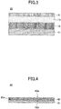
- a heat-ray-reflective, light-transmissive base material of the present embodiment may further include a surface protection layer 31 over a transparent conductive oxide layer 13, like a heat-ray-reflective, light-transmissive base material 30 illustrated in FIG. 3 .
- the heat-ray-reflective, light-transmissive base material 30 can have a hard-coat layer 12 and a light-transmissive base material 11 under the transparent conductive oxide layer 13 as illustrated in FIG. 3 .
- Providing the surface protection layer 31 enables to prevent the transparent conductive oxide layer 13 from being directly contacted by a human hand or the like; therefore, the abrasion resistance can be increased particularly.
- the thickness of a surface protection layer is favorably greater than or equal to 5 nm and less than or equal to 1 ⁇ m and more favorably greater than or equal to 5 nm and less than or equal to 500 nm. This is because setting the thickness of a surface protection layer to greater than or equal to 5 nm enables to protect the transparent conductive oxide layer 13 sufficiently and to increase the abrasion resistance particularly. Also, setting the thickness greater than 1 ⁇ m does not bring a significant difference in the effect, rather, may increase the emissivity due to far-infrared absorption. Therefore, the thickness of a surface protection layer is favorably less than or equal to 1 ⁇ m.
- an organic material or inorganic material is favorable.
- an actinic-ray-curable or thermosetting organic material such as a fluorine-based, acryl-based, urethane-based, ester-based, epoxy-based, silicone-based, or olefin-based material; or an organic-inorganic hybrid material in which an organic component and an inorganic component are chemically bonded, is favorably used.
- an inorganic material for example, a transparent oxide or the like that contains at least one species selected from among silicon, aluminum, zinc, titanium, zirconium, and tin as the main components; diamond-like carbon; or the like may be listed.
- a crosslinked structure In the case of using an organic material as the surface protection layer 31, it is favorable to introduce a crosslinked structure into the organic material. Forming a crosslinked structure increases the mechanical strength and chemical strength of the surface protection layer, and increases the protective function with respect to a transparent conductive oxide layer and the like. Among such structures, it is favorable to introduce a crosslinked structure derived from an ester compound having an acidic group and a polymerizable functional group in the same molecule.
- an ester compound having an acidic group and a polymerizable functional group in the same molecule an ester of a compound whose molecule contains a polyacid such as phosphoric acid, sulfuric acid, oxalic acid, succinic acid, phthalic acid, fumaric acid, or maleic acid; a polymerizable functional group such as an ethylenically unsaturated group, silanol group, or epoxy group; and a hydroxyl group may be listed.
- the ester compound may be a polyhydric ester such as a diester or triester, it is favorable that at least one acidic group of a polyacid is not esterified.
- the mechanical strength and chemical strength of the surface protection layer are increased, and the adhesiveness between the surface protection layer 31 and the transparent conductive oxide layer 13 is increased, by which the durability of the transparent conductive oxide layer is particularly increased.
- ester compounds described above an ester compound of phosphoric acid and an organic acid having a polymerizable functional group (phosphate ester compound) is excellent in adhesiveness to a transparent conductive oxide layer.
- a surface protection layer having a crosslinked structure derived from a phosphoric acid ester compound is excellent in adhesiveness to the transparent conductive oxide layer.
- an ester compound described above favorably contains a (meth)acryloyl group as a polymerizable functional group.
- an ester compound described above may have multiple polymerizable functional groups in a molecule.
- a phosphoric acid monoester compound or phosphoric acid diester compound expressed by the following formula (1) is used favorably. Note that a phosphoric acid monoester and a phosphoric acid diester may also be used together.
- X represents a hydrogen atom or a methyl group
- (Y) represents an - OCO(CH 2 ) 5 - group.
- n is 0 or 1 and p is 1 or 2.
- the content of the structure derived from an ester compound described above in a surface protection layer 31 is favorably greater than or equal to 1 mass% and less than or equal to 20 mass%, more favorably greater than or equal to 1.5 mass% and less than or equal to 17.5 mass%, even more favorably greater than or equal to 2 mass% and less than or equal to 15 mass%, and particularly favorably greater than or equal to 2.5 mass% and less than or equal to 12.5 mass%. If the content of the ester compound-derived structure is excessively low, the effect of improving the strength and adhesiveness may not be obtained sufficiently.
- the content of the ester compound-derived structure is excessively high, the curing rate when forming a surface protection layer decreases to reduce the hardness, or the slipperiness of the surface protection layer surface may be reduced to reduce the abrasion resistance.
- the content of the structure derived from an ester compound in a surface protection layer can be set in a desired range by adjusting the content of an ester compound described above in a composition when forming the surface protection layer.
- the method of forming a surface protection layer 31 is not limited in particular. It is favorable to form a surface protection layer by a method in which, for example, a solution is prepared by dissolving an organic material or a curable monomer or oligomer of an organic material, and an ester compound described above in a solvent; this solution is coated on a transparent conductive oxide layer 13; after the solvent is dried, the coated material is irradiated with ultraviolet rays or electron rays, or energized by heat, to be cured.
- a film may be formed by one or more types of dry processes selected from among, for example, sputtering, vacuum evaporation, CVD, electron beam evaporation, and the like.
- additives including a coupling agent such as a silane coupling agent or titanium coupling agent; a leveling agent; an ultraviolet absorber; an antioxidant; a heat stabilizer; a lubricant; a plasticizer; an anti-coloring agent; a flame retardant; and an antistatic agent, may be included.
- a surface protection layer 31 may be constituted with multiple layers of different materials, by laminating an inorganic material and an organic material.
- an emissivity measured from the side of a transparent conductive oxide layer is favorably less than or equal to 0.60, more favorably less than or equal to 0.50, and even more favorably less than or equal to 0.40.
- the lower limit value of the emissivity may be, although not limited in particular, for example, greater than 0 because a smaller value is more favorable.
- a heat-ray-reflective, light-transmissive base material of the present embodiment includes a light-transmissive base material, a hard-coat layer, and a transparent conductive oxide layer.
- the emissivity measured from the side of the transparent conductive oxide layer is an emissivity measured by having the transparent conductive oxide layer irradiated with infrared rays on a surface of the heat-ray-reflective, light-transmissive base material on the side closer to the transparent conductive oxide layer in the above three layers, among the surfaces of the heat-ray-reflective, light-transmissive base material.
- a heat-ray-reflective window 40 of the present embodiment includes a light-transmissive base material 41 for windows and a heat-ray-reflective, light-transmissive base material 42 described above disposed over one surface 41a of the light-transmissive base material 41 for windows.
- the light-transmissive base material 41 for windows is, for example, a light-transmissive base material disposed on the daylighting part of a window, and, for example, a glass material or a light-transmissive resin base material may be used.
- the heat-ray-reflective, light-transmissive base material 42 described above may be disposed on the one surface of the light-transmissive base material 41 for windows.
- the method of fixing the heat-ray-reflective, light-transmissive base material 42 on the light-transmissive base material 41 for windows is not limited in particular.
- the base material 42 can be fixed, for example, by disposing an adhesive layer or the like as described using FIG. 2 on the side 42b of the heat-ray-reflective, light-transmissive base material 42 facing the light-transmissive base material 41 for windows.
- the heat-ray-reflective, light-transmissive base material 42 is disposed on the side of a room interior relative to the light-transmissive base material 41 for windows. Therefore, in the example illustrated in FIG. 4 , it is favorable to fix the heat-ray-reflective, light-transmissive base material 42 such that the transparent conductive oxide layer is positioned on the side of the other surface 42a opposite to the one surface 42b facing the light-transmissive base material 41 for windows.
- the transparent conductive oxide layer has a function of reflecting far-infrared rays
- disposing the transparent conductive oxide layer to be oriented toward the interior of a room or the like enables to control emission of far-infrared rays generated inside the room or the like to the outside.
- a heat-ray-reflective window includes a heat-ray-reflective, light-transmissive base material described above. For this reason, it is possible to reflect far-infrared rays and to have a heat-insulating function. Also, the heat-ray-reflective window can be made to be excellent in abrasion resistance.
- a visible light transmittance was determined according to JIS A5759-2008 (films for building window glass) by using a spectrophotometer (product name "U-4100", manufactured by Hitachi High-Technologies Corporation).
- An emissivity was determined according to JIS R3106-2008 (test method of transmittance, reflectance, emissivity, and solar heat gain coefficient of plate glass), by measuring a positive reflectance obtained when the surface protection layer side was irradiated with infrared rays in a wavelength range of 5 ⁇ m to 25 ⁇ m by using a Fourier-transform infrared spectrometer (FT-IR) device (manufactured by Varian) equipped with a variable-angle reflection accessory.
- FT-IR Fourier-transform infrared spectrometer
- a heat-ray-reflective, light-transmissive base material was cut to have a size of 15 cm ⁇ 5 cm, and a surface on the side of the light-transmissive base material was bonded to a 1.5-mm glass via a 25- ⁇ m-thick adhesive layer, to be used as a sample.
- a 10-pens-equipped tester while applying a 1-kg load with steel wool (Bonstar #0000), a 10-cm-long range of the exposed surface of the heat-ray-reflective, light-transmissive base material fixed on the glass was rubbed with 10 reciprocal motions.
- the exposed surface of a heat-ray-reflective, light-transmissive base material means a surface of the surface protection layer in Examples 1 to 9, Examples 11 to 13, and Comparative Examples 1 and 2; or a surface of the conductive oxide layer in Example 10.
- the presence or absence of scratches or delamination on the transparent conductive oxide layer of a sample was visually evaluated according to the following evaluation criteria. Excellent: no scratch or delamination was confirmed on the transparent conductive oxide layer; Fair: a scratch or delamination was confirmed in part of the transparent conductive oxide layer; and Poor: a scratch or delamination was confirmed on the transparent conductive oxide layer.
- a heat-ray-reflective, light-transmissive base material having a configuration shown in Table 1 was produced and evaluated.
- the heat-ray-reflective, light-transmissive base material was produced to have a light-transmissive base material, a hard-coat layer, a transparent conductive oxide layer, and a surface protection layer as shown in Table 1.
- PET polyethylene terephthalate
- a resin solution was coated on one surface of the light-transmissive base material by spin coating, dried, and then, cured by ultraviolet (UV) irradiation (300 mJ/cm 2 ) under a nitrogen atmosphere to form a hard-coat layer having a thickness shown in Table 1.
- UV ultraviolet
- the resin solution was prepared by mixing an optical polymerization initiator (product name: Irgacure 184, manufactured by BASF) into a UV-curable urethane acrylate hard-coat resin solution (product name: ENS 1068, manufactured by DIC Corporation) to have a resin equivalent of 3 wt%.
- an optical polymerization initiator product name: Irgacure 184, manufactured by BASF
- a UV-curable urethane acrylate hard-coat resin solution product name: ENS 1068, manufactured by DIC Corporation
- ITO film indium tin oxide film
- a film was formed so as to have a thickness shown in Table 1 by DC magnetron sputtering, to which heat treatment was then applied at 150 °C for 30 minutes to complete the film.
- sputtering gas a mixed gas of argon and a small amount of oxygen was used, and the film was formed under a process pressure of 0.2 Pa.
- a surface protection layer was formed on the transparent conductive oxide layer.
- a mixed solution was prepared in which an optical polymerization initiator (manufactured by BASF, product name: Irgacure 127) was mixed into an acrylic hard-coat resin solution (manufactured by JSR Corporation, product name: Opstar Z7535) to have a resin equivalent of 3 wt%. Then, the mixed solution was coated on the transparent conductive oxide layer by spin coating so as to obtain a thickness shown in Table 1 after drying. After the drying, UV irradiation (300 mJ/cm 2 ) was carried out under a nitrogen atmosphere to cure the coating.
- the obtained heat-ray-reflective, light-transmissive base material was evaluated as described above. The results are shown in Table 1.
- a heat-ray-reflective, light-transmissive base material was produced and evaluated in substantially the same way as in Example 1 except that a transparent conductive oxide layer was formed so as to have a thickness shown in Table 1. The results are shown in Table 1.
- a heat-ray-reflective, light-transmissive base material was produced and evaluated in substantially the same way as in Example 1 except that a surface protection layer was formed so as to have a thickness shown in Table 1. The results are shown in Table 1.
- a heat-ray-reflective, light-transmissive base material was produced and evaluated in substantially the same way as in Example 1 except that a surface protection layer was configured as follows. The results are shown in Table 1.
- An oxide film containing Si and Zr (denoted as "SXO" in Table 1) was formed as a surface protection layer over the transparent conductive oxide layer. Specifically, a film was formed so as to have a thickness shown in Table 1 by DC magnetron sputtering using an alloy target having a Zr content of 30 wt% with respect to the total amount of metal Si and Zr.
- a heat-ray-reflective, light-transmissive base material was produced and evaluated in substantially the same way as in Example 1 except that a surface protection layer was formed so as to have a thickness shown in Table 1. The results are shown in Table 1.
- a heat-ray-reflective, light-transmissive base material was produced and evaluated in substantially the same way as in Example 1 except that as a transparent conductive oxide layer, instead of the ITO film, an IZO film (Indium Zinc Oxide film) was formed to have a thickness of 400 nm. The results are shown in Table 1.
- the IZO film was formed to have a thickness of 400 nm by DC magnetron sputtering using a complex oxide target having a ZnO content of 10 wt% with respect to the total amount of In 2 O 3 and ZnO.
- the sputtering gas a mixed gas of argon and a small amount of oxygen was used, and the film was formed under a process pressure is 0.2 Pa.
- a heat-ray-reflective, light-transmissive base material was produced and evaluated in substantially the same way as in Example 3 except that a hard-coat layer was formed so as to have a thickness shown in Table 1. The results are shown in Table 1.
- a heat-ray-reflective, light-transmissive base material was produced and evaluated in substantially the same way as in Example 1 except that a hard-coat layer was formed so as to have a thickness shown in Table 1. The results are shown in Table 1.
- a heat-ray-reflective, light-transmissive base material was produced and evaluated in substantially the same way as in Example 1 except that a blue plate glass (manufactured by Matsunami Glass Ind.,Ltd.) having a thickness of 3 mm was used as the light-transmissive base material and that a surface protection layer was not provided.
- the results are shown in Table 1.
- a heat-ray-reflective, light-transmissive base material was produced and evaluated in substantially the same way as in Example 1 except that a transparent conductive oxide layer was formed so as to have a thickness shown in Table 1. The results are shown in Table 1.
- a heat-ray-reflective, light-transmissive base material was produced and evaluated in substantially the same way as in Example 1 except that a surface protection layer was formed so as to have a thickness shown in Table 1. The results are shown in Table 1.
- a heat-ray-reflective, light-transmissive base material was produced and evaluated in substantially the same way as in Example 1 except that an underlayer was formed between the hard-coat layer and the transparent conductive oxide layer.
- Al oxide film as an adhesiveness improving layer as an underlayer on the hard-coat layer namely, an alumina film (denoted as "Al 2 O 3 " in Table 1) was formed.
- an underlayer was formed on the hard-coat layer by DC magnetron sputtering so as to have a thickness shown in Table 1.
- a transparent conductive oxide layer and a surface protection layer were formed on the underlayer in substantially the same way as in Example 1 to obtain a heat-ray-reflective, light-transmissive base material.
- a heat-ray-reflective, light-transmissive base material was produced and evaluated in substantially the same way as in Example 1 except that a hard-coat layer was not provided. The results are shown in Table 1.
- a heat-ray-reflective, light-transmissive base material was produced and evaluated in substantially the same way as in Example 1 except that an SiO 2 film was formed instead of the transparent conductive oxide layer. The results are shown in Table 1.
- the SiO 2 layer was formed so as to have a thickness of 80 nm by DC magnetron sputtering using a metal Si target.
- a mixed gas of argon/oxygen 85/15 (volume ratio) was used under a process pressure of 0.2 Pa.
- Example 1 to Example 13 Compared Example 1 to Example 13 with Comparative Example 2 having no transparent conductive oxide layer, in each of Example 1 to Example 13, the emissivity was significantly reduced as compared to Comparative Example 2, and it was also confirmed that providing a transparent conductive oxide layer enables to exhibit heat insulation.
- heat-ray-reflective, light-transmissive base materials and heat-ray-reflective windows have been described according to the embodiments, examples, and the like. Note that the present invention is not limited to the embodiments or examples described above. Various modifications and changes can be made within the scope of the invention as described in the claims.
Landscapes
- Physics & Mathematics (AREA)
- General Physics & Mathematics (AREA)
- Optics & Photonics (AREA)
- Engineering & Computer Science (AREA)
- Chemical & Material Sciences (AREA)
- Structural Engineering (AREA)
- Civil Engineering (AREA)
- Geochemistry & Mineralogy (AREA)
- Materials Engineering (AREA)
- Life Sciences & Earth Sciences (AREA)
- Organic Chemistry (AREA)
- Chemical Kinetics & Catalysis (AREA)
- General Chemical & Material Sciences (AREA)
- Toxicology (AREA)
- Architecture (AREA)
- Health & Medical Sciences (AREA)
- Laminated Bodies (AREA)
- Special Wing (AREA)
- Optical Filters (AREA)
- Surface Treatment Of Optical Elements (AREA)
- Surface Treatment Of Glass (AREA)
Abstract
Description
- The present invention relates to a heat-ray-reflective, light-transmissive base material, and a heat-ray-reflective window.
- Conventionally, a heat-ray-reflective, light-transmissive base material has been known that has a layer provided with a function of reflecting heat rays over a light-transmissive base material such as glass or resin.
- As such heat-ray-reflective, light-transmissive base materials, base materials have been studied conventionally that reflect part of visible light and near-infrared rays of sunlight or the like, to control incidence of near-infrared rays into the interior of a room or vehicle, so as to provide heat-shielding capability to control rise in temperature. Also, in recent years, studies are conducted on heat-ray-reflective, light-transmissive base materials that have reduced emissivity so as to provide heat insulation capability.
- For example, Patent Document 1 discloses a laminated-film-attached transparent substrate that includes a transparent conductive layer, and a laminated film over the transparent conductive layer in which a transparent conductive layer and a nitrogen-containing light-absorbing layer having a film thickness over 10 nm are laminated, with an object of providing a laminated-film-attached transparent substrate that is excellent in durability in addition to high heat-shielding performance and high color-rendering performance.
- Patent Document 1: Japanese Laid-Open Patent Application No.
2016-79051 - Meanwhile, a heat-ray-reflective, light-transmissive base material is used, because of its function, as the light-transmissive base material of a daylighting part such as a window, or in a form of being attached to the light-transmissive base material of a daylighting part such as a window; therefore, the base material often comes into contact with human hands and objects. For this reason, it has been desired for a heat-ray-reflective, light-transmissive base material to be preventive with respect to delamination or scratches in a functional layer such as a transparent conductive layer constituting the heat-ray-reflective, light-transmissive base material, so that the function is not reduced and/or the appearance is not impaired, even when a human hand, object, or the like moves on the surface of the heat-ray-reflective, light-transmissive base material in a state of applying pressure to the surface to cause friction. In short, a heat-ray-reflective, light-transmissive base material excellent in abrasion resistance has been desired.
- However, such abrasion resistance has not been sufficiently studied for the laminated-film-attached transparent substrate disclosed in Patent Document 1.
- Thereupon, in view of the above problem of the conventional technology, it is an object of an aspect of the present invention to provide a heat-ray-reflective, light-transmissive base material that is excellent in abrasion resistance.
- To solve the above problem, according to an aspect of the present invention, a heat-ray-reflective, light-transmissive base material is provided that includes a light-transmissive base material; a hard-coat layer disposed over one surface of the light-transmissive base material; and a transparent conductive oxide layer containing a transparent conductive oxide, disposed over the hard-coat layer.
- According to an aspect of the present invention, it is possible to provide a heat-ray-reflective, light-transmissive base material excellent in abrasion resistance.
-
-
FIG. 1 is a cross-sectional view of a heat-ray-reflective, light-transmissive base material in one configuration example according to an embodiment of the present invention; -
FIG. 2 is a cross-sectional view of a heat-ray-reflective, light-transmissive base material in another configuration example according to an embodiment of the present invention; -
FIG. 3 is a cross-sectional view of a heat-ray-reflective, light-transmissive base material in yet another configuration example according to an embodiment of the present invention; and -
FIG. 4 is a cross-sectional view of a heat-ray-reflective window in one configuration example according to an embodiment of the present invention. - In the following, an embodiment (referred to as "the present embodiment", below) of the present disclosure will be described in detail; note that the present embodiment is not limited by such details.
- One configuration example of a heat-ray-reflective, light-transmissive base material of the present embodiment will be described below.
- A heat-ray-reflective, light-transmissive base material of the present embodiment includes a light-transmissive base material; a hard-coat layer disposed over one surface of the light-transmissive base material; and a transparent conductive oxide layer containing a transparent conductive oxide, disposed over the hard-coat layer.
- The inventors of the present invention conducted intensive investigations on heat-ray-reflective, light-transmissive base materials whose emissivity is reduced to provide heat insulation capability, so as to obtain a heat-ray-reflective, light-transmissive base material that is also excellent in abrasion resistance.
- As a result, first, a finding was obtained that providing a transparent conductive oxide layer containing a transparent conductive oxide enables to obtain a heat-ray-reflective, light-transmissive base material having heat insulation capability. One can consider that this is because far-infrared rays can be reflected by using carriers held by the transparent conductive oxide contained in the transparent conductive oxide layer.
- However, simply disposing the transparent conductive oxide layer over the light-transmissive base material may result in a case where scratches or delamination are generated on the transparent conductive oxide layer, for example, when a hand or object moves on the heat-ray-reflective, light-transmissive base material in a state of applying pressure to the surface to cause friction, and thereby, deforms the transparent conductive oxide layer. If scratches or delamination are generated on the transparent conductive oxide layer, the function of the transparent conductive oxide layer may be reduced or the appearance may be impaired.
- Thereupon, the inventors found that disposing a hard-coat layer over a light-transmissive base material enables to control generation of scratches or delamination, namely, enables to raise the abrasion resistance, even when the transparent conductive oxide layer is pressed or rubbed, and thus, completed the present invention.
- Here, a configuration example of a heat-ray-reflective, light-transmissive base material of the present embodiment is illustrated in
FIG. 1. FIG. 1 schematically illustrates a cross-sectional view of a heat-ray-reflective, light-transmissive base material of the present embodiment on a plane parallel to the laminating direction of a light-transmissive base material, a hard-coat layer, and a transparent conductive oxide layer. - As illustrated in
FIG. 1 , a heat-ray-reflective, light-transmissive base material 10 of the present embodiment may have a structure in which a hard-coat layer 12 and a transparentconductive oxide layer 13 disposed over the hard-coat layer 12 are laminated over one surface of a light-transmissive base material 11. In the following, each of the layers will be described. - As the light-
transmissive base material 11, various light-transmissive base materials capable of transmitting visible light can be used favorably. As the light-transmissive base material 11, one having visible light transmittance greater than or equal to 10% can be used more favorably. Note that in the present description, a visible light transmittance is measured in accordance with JIS A5759-2008 (films for building window glass). - As the light-
transmissive base material 11, a glass plate, a light-transmissive resin base material, or the like can be used favorably. A heat-ray-reflective, light-transmissive base material of the present embodiment can control deformation of the transparent conductive oxide layer and can increase the abrasion resistance by providing the hard-coat layer. Moreover, the effect can be exhibited especially in the case of the light-transmissive base material being particularly easy to deform, such as a light-transmissive resin base material. For this reason, the light-transmissive base material of a heat-ray-reflective, light-transmissive base material of the present embodiment is more favorably a light-transmissive resin base material. - As the material of a light-transmissive resin base material, any material can be used favorably as long as being capable of transmitting visible light as described above. In addition, since heat treatment or the like needs to be carried out when forming layers over the light-
transmissive base material 11, a resin that has heat resistance may be used favorably. As resin materials constituting a light-transmissive resin base material, one or more species selected from among, for example, polyethylene terephthalate (PET), polyethylene naphthalate (PEN), polyetheretherketone (PEEK), polycarbonate (PC), and the like may be used favorably. - A heat-ray-reflective, light-transmissive base material of the present embodiment can be used in a form of, for example, being fitted into a window frame or the like as the light-transmissive base material of a daylighting part such as a window, or being attached to the light-transmissive base material of a daylighting part such as a window. For this reason, the thickness and material can be selected for the light-
transmissive base material 11 depending on the use and the like. The light-transmissive base material 11 may have a thickness, for example, greater than or equal to 10 µm and less than or equal to 10 mm. - For example, in the case of using a heat-ray-reflective, light-transmissive base material of the present embodiment as the light-transmissive base material of a daylighting part such as a window, it is favorable to select the thickness and material of the light-
transmissive base material 11 such that the light-transmissive base material 11 has sufficient strength. - Alternatively, in the case of using a heat-ray-reflective, light-transmissive base material of the present embodiment by attaching to the light-transmissive base material of a daylighting part such as a window, it is favorable to select the thickness and material of the light-
transmissive base material 11 to have flexibility so as to be easily attachable to the light-transmissive base material of the window or the like, and to improve the productivity of a heat-ray-reflective substrate. In the case of adopting a light-transmissive base material having flexibility, a light-transmissive resin base material is used favorably as the light-transmissive base material. In the case of using a light-transmissive resin base material as a light-transmissive base material having flexibility, the thickness is favorably within a range greater than or equal to 10 µm and less than or equal to 300 µm. - Note that the light-
transmissive base material 11 may be constituted with a single sheet of a light-transmissive base material, or may be constituted with two or more sheets of a light-transmissive base material that are bonded to each other to be combined to be used. In the case of using a combination of two or more sheets of a light-transmissive base material that are bonded to each other, it is favorable that the total thickness falls within, for example, a favorable thickness range for a single light-transmissive base material as described above. - The hard-
coat layer 12 supports the transparentconductive oxide layer 13 and can control deformation of the transparentconductive oxide layer 13 when pressed or the like. - The hard-
coat layer 12 can be formed by using, for example, a resin, to be formed as a resin hard-coat layer. The material of the hard-coat layer is not limited in particular. For example, one or more resins selected from among acrylic resins, silicone resins, urethane resins, and the like can be favorably used. - Further, a hard-coat layer containing inorganic particles can be expected to improve adhesiveness between the hard-coat layer and a transparent conductive layer. Although the material of inorganic particles is not limited in particular, for example, one or more species of inorganic particles selected from among silica, alumina, zirconia, and the like can be favorably used.
- The hard-
coat layer 12 can be formed, for example, by coating a resin on one surface of the light-transmissive base material 11 or the like and curing the resin. - The thickness of the hard-
coat layer 12 is not limited in particular, and can be selected discretionarily depending on the material of the hard-coat layer 12 and/or required levels of visible light transmittance, abrasion resistance, and the like. For example, the thickness of the hard-coat layer 12 is favorably greater than or equal to 0.5 µm and less than or equal to 10 µm, and more favorably greater than or equal to 0.7 µm and less than or equal to 5 µm. - This is because setting the thickness of the hard-
coat layer 12 to be greater than or equal to 0.5 µm enables to obtain a hard-coat layer having sufficient strength, and enables to control deformation of the transparentconductive oxide layer 13 particularly. This is also because setting the thickness of the hard-coat layer 12 to be less than or equal to 10 µm enables to control the internal stress that is generated by contraction of the hard-coat layer. - The transparent
conductive oxide layer 13 is a layer containing a transparent conductive oxide, and may also be a layer formed of a transparent conductive oxide. According to the investigations of the inventors of the present invention, far-infrared rays can be reflected by carriers contained in a transparent conductive oxide. For this reason, a heat-ray-reflective, light-transmissive base material of the present embodiment can be made as a heat-ray-reflective, light-transmissive base material excellent in heat insulation by providing a transparent conductive oxide layer. - A transparent conductive oxide contained in a transparent conductive oxide layer is not limited in particular, and various transparent conductive oxides can be used as long as the material can reflect far-infrared rays. However, as described above, considering carriers to reflect far-infrared rays, the transparent conductive oxide favorably contains, for example, one or more species selected from among an indium oxide doped with one or more species selected from among tin, titanium, tungsten, molybdenum, zinc, and hydrogen; a tin oxide doped with one or more species selected from among antimony, indium, tantalum, chlorine, and fluorine; and a zinc oxide doped with one or more species selected from among indium, aluminum, tin, gallium, fluorine, and boron.
- As the transparent conductive oxide, an indium oxide doped with one or more species selected from among tin, titanium, tungsten, molybdenum, zinc, and hydrogen is more favorable; and an indium oxide doped with one or more species selected from among tin and zinc is even more favorable.
- The thickness of a transparent conductive oxide layer is not limited in particular, and can be discretionarily selected depending on required levels of heat insulation and the like. For example, the thickness of a transparent conductive oxide layer is favorably greater than or equal to 30 nm and less than or equal to 500 nm, and more favorably greater than or equal to 35 nm and less than or equal to 400 nm.
- This is because setting the thickness of a transparent conductive oxide layer to be greater than or equal to 30 nm enables to reflect far-infrared rays in particular and to improve the heat insulation performance. This is also because setting the thickness of the transparent conductive oxide layer to be less than or equal to 500 nm enables to maintain sufficiently high visible light transmittance.
- The film-forming method of a transparent conductive oxide layer is not limited in particular; for example, a film-forming method using one or more types of dry processes selected from among sputtering, vacuum evaporation, CVD, electron beam evaporation, and the like can be used favorably. In addition, it is favorable to carry out heat treatment after the film formation to increase crystallinity.
- A heat-ray-reflective, light-transmissive base material of the present embodiment is not limited to have only a light-transmissive base material, a hard-coat layer, and a transparent conductive oxide layer as described above, and may further have an optional layer.
- For example, an underlayer such as an optical adjustment layer, a gas barrier layer, an adhesiveness improving layer, or the like can be provided between the hard-coat layer and the transparent conductive oxide layer. An optical adjustment layer enables to improve color tone and transparency; a gas barrier layer enables to improve the crystallization rate of a transparent conductive oxide; and an adhesiveness improving layer enables to improve durability such as delamination resistance between layers and cracking resistance.
- Although underlayers to be configured are not limited in particular, as an adhesiveness improving layer and/or a gas barrier layer, for example, a layer containing alumina (Al2O3) may be listed. Also, as an optical adjustment layer, a layer containing zirconia (ZrO2), a layer containing hollow particles, or the like may be listed.
- For example, a heat-ray-reflective, light-transmissive base material of the present embodiment may include, like a heat-ray-reflective, light-
transmissive base material 20 illustrated inFIG. 2 , anadhesive layer 21 on theother surface 11b opposite to the onesurface 11a of a light-transmissive base material 11, over which a hard-coat layer 12 and a transparentconductive oxide layer 13 are provided. - A heat-ray-reflective, light-transmissive base material of the present embodiment may also be used in a form of being attached to the light-transmissive base material of a daylighting part such as a window as described above. Therefore, providing an
adhesive layer 21 as described above eases the work of attaching to the light-transmissive base material of a daylighting part such as a window. - Although the material of an adhesive layer is not limited in particular, it is favorable to use a material having high visible light transmittance. As the material of an adhesive layer, for example, an acrylic adhesive, rubber-based adhesive, silicone-based adhesive, or the like may be used. Among these, an acrylic adhesive containing an acrylic polymer as the main component is excellent in optical transparency, exhibits appropriate wettability, cohesiveness, and adhesiveness, and is excellent in weather resistance, heat resistance, and the like; therefore, it is favorable as the material of an adhesive layer.
- It is favorable that an adhesive layer has high visible light transmittance and low ultraviolet transmittance. Lowering the ultraviolet light transmittance of an adhesive layer enables to control deterioration of a light-transmissive base material, a hard-coat layer, and a transparent conductive oxide layer caused by ultraviolet light such as sunlight. From the viewpoint of lowering the ultraviolet light transmittance of an adhesive layer, the adhesive layer may also contain an ultraviolet absorber. Note that deterioration of a transparent conductive oxide layer and the like caused by ultraviolet rays from outdoors may also be controlled by using a light-transmissive base material or the like that contains an ultraviolet absorber. It is favorable to cover an exposed surface of an adhesive layer by a release paper temporarily attached to the surface for the purpose of preventing contamination of the exposed surface until the heat-ray-reflective, light-transmissive base material is put to practical use. Thereby, contamination caused by contact with the exterior of the exposed surface of the adhesive layer can be prevented in a normal handling state.
- In the case of using a heat-ray-reflective, light-transmissive base material of the present embodiment as the light-transmissive base material of a daylighting part such as a window by fitting into the window frame or the like, there is no need to attach to another light-transmissive base material; therefore, it is favorable not to have an adhesive layer.
- In addition, a heat-ray-reflective, light-transmissive base material of the present embodiment may further include a
surface protection layer 31 over a transparentconductive oxide layer 13, like a heat-ray-reflective, light-transmissive base material 30 illustrated inFIG. 3 . Note that the heat-ray-reflective, light-transmissive base material 30 can have a hard-coat layer 12 and a light-transmissive base material 11 under the transparentconductive oxide layer 13 as illustrated inFIG. 3 . - Providing the
surface protection layer 31 enables to prevent the transparentconductive oxide layer 13 from being directly contacted by a human hand or the like; therefore, the abrasion resistance can be increased particularly. - The thickness of a surface protection layer is favorably greater than or equal to 5 nm and less than or equal to 1 µm and more favorably greater than or equal to 5 nm and less than or equal to 500 nm. This is because setting the thickness of a surface protection layer to greater than or equal to 5 nm enables to protect the transparent
conductive oxide layer 13 sufficiently and to increase the abrasion resistance particularly. Also, setting the thickness greater than 1 µm does not bring a significant difference in the effect, rather, may increase the emissivity due to far-infrared absorption. Therefore, the thickness of a surface protection layer is favorably less than or equal to 1 µm. - As the material of a
surface protection layer 31, one having high visible light transmittance and being excellent in mechanical strength and chemical strength is favorable. From the viewpoint of enhancing the abrasion resistance and the chemical protection effect of a transparent conductive oxide layer, an organic material or inorganic material is favorable. As an organic material, for example, an actinic-ray-curable or thermosetting organic material such as a fluorine-based, acryl-based, urethane-based, ester-based, epoxy-based, silicone-based, or olefin-based material; or an organic-inorganic hybrid material in which an organic component and an inorganic component are chemically bonded, is favorably used. - Also, as an inorganic material, for example, a transparent oxide or the like that contains at least one species selected from among silicon, aluminum, zinc, titanium, zirconium, and tin as the main components; diamond-like carbon; or the like may be listed.
- In the case of using an organic material as the
surface protection layer 31, it is favorable to introduce a crosslinked structure into the organic material. Forming a crosslinked structure increases the mechanical strength and chemical strength of the surface protection layer, and increases the protective function with respect to a transparent conductive oxide layer and the like. Among such structures, it is favorable to introduce a crosslinked structure derived from an ester compound having an acidic group and a polymerizable functional group in the same molecule. - As an ester compound having an acidic group and a polymerizable functional group in the same molecule, an ester of a compound whose molecule contains a polyacid such as phosphoric acid, sulfuric acid, oxalic acid, succinic acid, phthalic acid, fumaric acid, or maleic acid; a polymerizable functional group such as an ethylenically unsaturated group, silanol group, or epoxy group; and a hydroxyl group may be listed. Note that although the ester compound may be a polyhydric ester such as a diester or triester, it is favorable that at least one acidic group of a polyacid is not esterified.
- In the case of the
surface protection layer 31 having a crosslinked structure derived from an ester compound described above, the mechanical strength and chemical strength of the surface protection layer are increased, and the adhesiveness between thesurface protection layer 31 and the transparentconductive oxide layer 13 is increased, by which the durability of the transparent conductive oxide layer is particularly increased. Among ester compounds described above, an ester compound of phosphoric acid and an organic acid having a polymerizable functional group (phosphate ester compound) is excellent in adhesiveness to a transparent conductive oxide layer. In particular, a surface protection layer having a crosslinked structure derived from a phosphoric acid ester compound is excellent in adhesiveness to the transparent conductive oxide layer. - From the viewpoint of increasing the mechanical strength and chemical strength of the
surface protection layer 31, an ester compound described above favorably contains a (meth)acryloyl group as a polymerizable functional group. Also, from the viewpoint of making the introduction of a cross-linked structure easier, an ester compound described above may have multiple polymerizable functional groups in a molecule. As an ester compound described above, for example, a phosphoric acid monoester compound or phosphoric acid diester compound expressed by the following formula (1) is used favorably. Note that a phosphoric acid monoester and a phosphoric acid diester may also be used together.
- The content of the structure derived from an ester compound described above in a
surface protection layer 31 is favorably greater than or equal to 1 mass% and less than or equal to 20 mass%, more favorably greater than or equal to 1.5 mass% and less than or equal to 17.5 mass%, even more favorably greater than or equal to 2 mass% and less than or equal to 15 mass%, and particularly favorably greater than or equal to 2.5 mass% and less than or equal to 12.5 mass%. If the content of the ester compound-derived structure is excessively low, the effect of improving the strength and adhesiveness may not be obtained sufficiently. On the other hand, if the content of the ester compound-derived structure is excessively high, the curing rate when forming a surface protection layer decreases to reduce the hardness, or the slipperiness of the surface protection layer surface may be reduced to reduce the abrasion resistance. The content of the structure derived from an ester compound in a surface protection layer can be set in a desired range by adjusting the content of an ester compound described above in a composition when forming the surface protection layer. - The method of forming a
surface protection layer 31 is not limited in particular. It is favorable to form a surface protection layer by a method in which, for example, a solution is prepared by dissolving an organic material or a curable monomer or oligomer of an organic material, and an ester compound described above in a solvent; this solution is coated on a transparentconductive oxide layer 13; after the solvent is dried, the coated material is irradiated with ultraviolet rays or electron rays, or energized by heat, to be cured. - Also, in the case of using an inorganic material as the material of a
surface protection layer 31, a film may be formed by one or more types of dry processes selected from among, for example, sputtering, vacuum evaporation, CVD, electron beam evaporation, and the like. - Note that other than organic materials and inorganic materials described above, as materials of a
surface protection layer 31, additives including a coupling agent such as a silane coupling agent or titanium coupling agent; a leveling agent; an ultraviolet absorber; an antioxidant; a heat stabilizer; a lubricant; a plasticizer; an anti-coloring agent; a flame retardant; and an antistatic agent, may be included. - Furthermore, a
surface protection layer 31 may be constituted with multiple layers of different materials, by laminating an inorganic material and an organic material. - Although characteristics required for a heat-ray-reflective, light-transmissive base material of the present embodiment are not limited in particular, an emissivity measured from the side of a transparent conductive oxide layer is favorably less than or equal to 0.60, more favorably less than or equal to 0.50, and even more favorably less than or equal to 0.40.
- This is because setting the emissivity to be less than or equal to 0.60 enables to obtain a heat-ray-reflective, light-transmissive base material having sufficient heat insulation performance, which is favorable. The lower limit value of the emissivity may be, although not limited in particular, for example, greater than 0 because a smaller value is more favorable.
- As described above, a heat-ray-reflective, light-transmissive base material of the present embodiment includes a light-transmissive base material, a hard-coat layer, and a transparent conductive oxide layer. Here, the emissivity measured from the side of the transparent conductive oxide layer is an emissivity measured by having the transparent conductive oxide layer irradiated with infrared rays on a surface of the heat-ray-reflective, light-transmissive base material on the side closer to the transparent conductive oxide layer in the above three layers, among the surfaces of the heat-ray-reflective, light-transmissive base material.
- Next, a configuration example of a heat-ray-reflective window of the present embodiment will be described. As illustrated in
FIG. 4 , a heat-ray-reflective window 40 of the present embodiment includes a light-transmissive base material 41 for windows and a heat-ray-reflective, light-transmissive base material 42 described above disposed over onesurface 41a of the light-transmissive base material 41 for windows. - The light-
transmissive base material 41 for windows is, for example, a light-transmissive base material disposed on the daylighting part of a window, and, for example, a glass material or a light-transmissive resin base material may be used. - The heat-ray-reflective, light-
transmissive base material 42 described above may be disposed on the one surface of the light-transmissive base material 41 for windows. The method of fixing the heat-ray-reflective, light-transmissive base material 42 on the light-transmissive base material 41 for windows is not limited in particular. For example, thebase material 42 can be fixed, for example, by disposing an adhesive layer or the like as described usingFIG. 2 on theside 42b of the heat-ray-reflective, light-transmissive base material 42 facing the light-transmissive base material 41 for windows. - When fixing the heat-ray-reflective, light-
transmissive base material 42 on the light-transmissive base material 41 for windows, it is favorable to carry out the fixation such that the transparent conductive oxide layer is positioned on the side of the interior of a room or vehicle. In other words, it is favorable to fix the heat-ray-reflective, light-transmissive base material 42 such that the transparent conductive oxide layer is positioned closer on the side of the interior of a room or vehicle than the light-transmissive base material included in the heat-ray-reflective, light-transmissive base material 42. - Normally, the heat-ray-reflective, light-
transmissive base material 42 is disposed on the side of a room interior relative to the light-transmissive base material 41 for windows. Therefore, in the example illustrated inFIG. 4 , it is favorable to fix the heat-ray-reflective, light-transmissive base material 42 such that the transparent conductive oxide layer is positioned on the side of theother surface 42a opposite to the onesurface 42b facing the light-transmissive base material 41 for windows. - This is because since the transparent conductive oxide layer has a function of reflecting far-infrared rays, disposing the transparent conductive oxide layer to be oriented toward the interior of a room or the like, enables to control emission of far-infrared rays generated inside the room or the like to the outside.
- According to the present embodiment, a heat-ray-reflective window includes a heat-ray-reflective, light-transmissive base material described above. For this reason, it is possible to reflect far-infrared rays and to have a heat-insulating function. Also, the heat-ray-reflective window can be made to be excellent in abrasion resistance.
- In the following, specific examples will be described; note that the present invention is not limited to these examples.
- A visible light transmittance was determined according to JIS A5759-2008 (films for building window glass) by using a spectrophotometer (product name "U-4100", manufactured by Hitachi High-Technologies Corporation).
- An emissivity was determined according to JIS R3106-2008 (test method of transmittance, reflectance, emissivity, and solar heat gain coefficient of plate glass), by measuring a positive reflectance obtained when the surface protection layer side was irradiated with infrared rays in a wavelength range of 5 µm to 25 µm by using a Fourier-transform infrared spectrometer (FT-IR) device (manufactured by Varian) equipped with a variable-angle reflection accessory.
- A heat-ray-reflective, light-transmissive base material was cut to have a size of 15 cm × 5 cm, and a surface on the side of the light-transmissive base material was bonded to a 1.5-mm glass via a 25-µm-thick adhesive layer, to be used as a sample. By using a 10-pens-equipped tester, while applying a 1-kg load with steel wool (Bonstar #0000), a 10-cm-long range of the exposed surface of the heat-ray-reflective, light-transmissive base material fixed on the glass was rubbed with 10 reciprocal motions. Note that the exposed surface of a heat-ray-reflective, light-transmissive base material means a surface of the surface protection layer in Examples 1 to 9, Examples 11 to 13, and Comparative Examples 1 and 2; or a surface of the conductive oxide layer in Example 10.
- After the test, the presence or absence of scratches or delamination on the transparent conductive oxide layer of a sample was visually evaluated according to the following evaluation criteria.
Excellent: no scratch or delamination was confirmed on the transparent conductive oxide layer;
Fair: a scratch or delamination was confirmed in part of the transparent conductive oxide layer; and
Poor: a scratch or delamination was confirmed on the transparent conductive oxide layer. - A heat-ray-reflective, light-transmissive base material having a configuration shown in Table 1 was produced and evaluated.
- The heat-ray-reflective, light-transmissive base material was produced to have a light-transmissive base material, a hard-coat layer, a transparent conductive oxide layer, and a surface protection layer as shown in Table 1.
- As the light-transmissive base material, a 50-µm-thick polyethylene terephthalate (PET) film (product name: T602E50, manufactured by Mitsubishi Plastics, Inc.) was used.
- A resin solution was coated on one surface of the light-transmissive base material by spin coating, dried, and then, cured by ultraviolet (UV) irradiation (300 mJ/cm2) under a nitrogen atmosphere to form a hard-coat layer having a thickness shown in Table 1.
- The resin solution was prepared by mixing an optical polymerization initiator (product name: Irgacure 184, manufactured by BASF) into a UV-curable urethane acrylate hard-coat resin solution (product name: ENS 1068, manufactured by DIC Corporation) to have a resin equivalent of 3 wt%.
- An ITO film (indium tin oxide film) was formed as the transparent conductive oxide layer over the hard-coat layer. Specifically, using a complex oxide target having an SnO2 content of 10 wt% with respect to the total amount of In2O3 and SnO2, a film was formed so as to have a thickness shown in Table 1 by DC magnetron sputtering, to which heat treatment was then applied at 150 °C for 30 minutes to complete the film.
- As the sputtering gas, a mixed gas of argon and a small amount of oxygen was used, and the film was formed under a process pressure of 0.2 Pa.
- A surface protection layer was formed on the transparent conductive oxide layer. Specifically, a mixed solution was prepared in which an optical polymerization initiator (manufactured by BASF, product name: Irgacure 127) was mixed into an acrylic hard-coat resin solution (manufactured by JSR Corporation, product name: Opstar Z7535) to have a resin equivalent of 3 wt%. Then, the mixed solution was coated on the transparent conductive oxide layer by spin coating so as to obtain a thickness shown in Table 1 after drying. After the drying, UV irradiation (300 mJ/cm2) was carried out under a nitrogen atmosphere to cure the coating.
- The obtained heat-ray-reflective, light-transmissive base material was evaluated as described above. The results are shown in Table 1.
- A heat-ray-reflective, light-transmissive base material was produced and evaluated in substantially the same way as in Example 1 except that a transparent conductive oxide layer was formed so as to have a thickness shown in Table 1. The results are shown in Table 1.
- A heat-ray-reflective, light-transmissive base material was produced and evaluated in substantially the same way as in Example 1 except that a surface protection layer was formed so as to have a thickness shown in Table 1. The results are shown in Table 1.
- A heat-ray-reflective, light-transmissive base material was produced and evaluated in substantially the same way as in Example 1 except that a surface protection layer was configured as follows. The results are shown in Table 1.
- An oxide film containing Si and Zr (denoted as "SXO" in Table 1) was formed as a surface protection layer over the transparent conductive oxide layer. Specifically, a film was formed so as to have a thickness shown in Table 1 by DC magnetron sputtering using an alloy target having a Zr content of 30 wt% with respect to the total amount of metal Si and Zr.
- As the sputtering gas, a mixed gas of argon/oxygen = 85/15 (volume ratio) was used, and the film was formed under a process gas pressure of 0.2 Pa.
- The evaluation results are shown in Table 1.
- A heat-ray-reflective, light-transmissive base material was produced and evaluated in substantially the same way as in Example 1 except that a surface protection layer was formed so as to have a thickness shown in Table 1. The results are shown in Table 1.
- A heat-ray-reflective, light-transmissive base material was produced and evaluated in substantially the same way as in Example 1 except that as a transparent conductive oxide layer, instead of the ITO film, an IZO film (Indium Zinc Oxide film) was formed to have a thickness of 400 nm. The results are shown in Table 1.
- The IZO film was formed to have a thickness of 400 nm by DC magnetron sputtering using a complex oxide target having a ZnO content of 10 wt% with respect to the total amount of In2O3 and ZnO.
- Note that as the sputtering gas, a mixed gas of argon and a small amount of oxygen was used, and the film was formed under a process pressure is 0.2 Pa.
- The evaluation results are shown in Table 1.
- A heat-ray-reflective, light-transmissive base material was produced and evaluated in substantially the same way as in Example 3 except that a hard-coat layer was formed so as to have a thickness shown in Table 1. The results are shown in Table 1.
- A heat-ray-reflective, light-transmissive base material was produced and evaluated in substantially the same way as in Example 1 except that a hard-coat layer was formed so as to have a thickness shown in Table 1. The results are shown in Table 1.
- A heat-ray-reflective, light-transmissive base material was produced and evaluated in substantially the same way as in Example 1 except that a blue plate glass (manufactured by Matsunami Glass Ind.,Ltd.) having a thickness of 3 mm was used as the light-transmissive base material and that a surface protection layer was not provided. The results are shown in Table 1.
- A heat-ray-reflective, light-transmissive base material was produced and evaluated in substantially the same way as in Example 1 except that a transparent conductive oxide layer was formed so as to have a thickness shown in Table 1. The results are shown in Table 1.
- A heat-ray-reflective, light-transmissive base material was produced and evaluated in substantially the same way as in Example 1 except that a surface protection layer was formed so as to have a thickness shown in Table 1. The results are shown in Table 1.
- A heat-ray-reflective, light-transmissive base material was produced and evaluated in substantially the same way as in Example 1 except that an underlayer was formed between the hard-coat layer and the transparent conductive oxide layer.
- An Al oxide film as an adhesiveness improving layer as an underlayer on the hard-coat layer, namely, an alumina film (denoted as "Al2O3" in Table 1) was formed. Specifically, using a metal Al target, an underlayer was formed on the hard-coat layer by DC magnetron sputtering so as to have a thickness shown in Table 1.
- As the sputtering gas, a mixed gas of argon/oxygen = 85/15 (volume ratio) was used, and the film was formed under a process gas pressure of 0.2 Pa.
- After having formed the underlayer, a transparent conductive oxide layer and a surface protection layer were formed on the underlayer in substantially the same way as in Example 1 to obtain a heat-ray-reflective, light-transmissive base material.
- The evaluation results are shown in Table 1.
- A heat-ray-reflective, light-transmissive base material was produced and evaluated in substantially the same way as in Example 1 except that a hard-coat layer was not provided. The results are shown in Table 1.
- A heat-ray-reflective, light-transmissive base material was produced and evaluated in substantially the same way as in Example 1 except that an SiO2 film was formed instead of the transparent conductive oxide layer. The results are shown in Table 1.
- The SiO2 layer was formed so as to have a thickness of 80 nm by DC magnetron sputtering using a metal Si target. As the sputtering gas, a mixed gas of argon/oxygen = 85/15 (volume ratio) was used under a process pressure of 0.2 Pa.
- The evaluation results are shown in Table 1.
[Table 1] Configuration of heat-ray-reflective, light-transmissive base material Evaluation results Light-transmis-sive base material Hard coat layer Underlayer Transparent conductive oxide layer Surface protective layer Optical characteristics Abrasion resistance Material Thickness (µm) Material Thickness (nm) Material of transparent conductive oxide Thickness (nm) Material Thickness (nm) Visible light transmittance (%) Emis-sivity Ex. 1 PET Urethane acrylate 2 None - ITO 80 Acrylate 100 92 0.30 Excellent Ex. 2 PET Urethane acrylate 2 None - ITO 40 Acrylate 100 92 0.45 Excellent Ex. 3 PET Urethane acrylate 2 None - ITO 150 Acrylate 100 92 0.15 Excellent Ex. 4 PET Urethane acrylate 2 None - ITO 80 Acrylate 450 88 0.44 Excellent Ex. 5 PET Urethane acrylate 2 None - ITO 80 SXO 10 84 0.30 Excellent Ex. 6 PET Urethane acrylate 2 None - ITO 80 Acrylate 40 87 0.30 Excellent Ex. 7 PET Urethane acrylate 2 None - IZO 400 Acrylate 100 85 0.28 Excellent Ex. 8 PET Urethane acrylate 1 None - ITO 150 Acrylate 100 92 0.15 Excellent Ex. 9 PET Urethane acrylate 0.5 None - ITO 80 Acrylate 100 92 0.30 Fair Ex. 10 Glass Urethane acrylate 2 None - ITO 80 None - 83 0.30 Excellent Ex. 11 PET Urethane acrylate 2 None - ITO 30 Acrylate 100 91 0.55 Excellent Ex. 12 PET Urethane acrylate 2 None - ITO 80 Acrylate 1000 88 0.60 Excellent Ex. 13 PET Urethane acrylate 2 Al2O3 3 ITO 80 Acrylate 100 92 0.30 Excellent Comp. ex. 1 PET None - None - ITO 80 Acrylate 100 92 0.30 Poor Comp. ex. 2 PET Urethane acrylate 2 None - SiO2 80 Acrylate 100 90 0.86 Excellent - According to the results shown in Table 1, comparing Example 1 to Example 13 with Comparative Example 1, it was confirmed that provinding a hardcoat layer enabled to obtain a heat-ray-reflective light-transmissive base material having excellent abrasion resistance. One can understand that this is because providing a hard-coat layer enables to control deformation of a transparent conductive oxide layer even when pressed, and to control generation of scratches and delamination due to friction.
- Also, comparing Example 1 to Example 13 with Comparative Example 2 having no transparent conductive oxide layer, in each of Example 1 to Example 13, the emissivity was significantly reduced as compared to Comparative Example 2, and it was also confirmed that providing a transparent conductive oxide layer enables to exhibit heat insulation.
- As above, heat-ray-reflective, light-transmissive base materials and heat-ray-reflective windows have been described according to the embodiments, examples, and the like. Note that the present invention is not limited to the embodiments or examples described above. Various modifications and changes can be made within the scope of the invention as described in the claims.
- This application claims priorities based on Japanese Patent Application No.
2017-073174 2018-049516 2017-073174 2018-049516 -
- 10, 20, 30, 42 heat-ray-reflective, light-transmissive base material
- 11 light-transmissive base material
- 12 hard-coat layer
- 13 transparent conductive oxide layer
- 21 adhesive layer
- 31 surface protection layer
- 40 heat-ray-reflective window
- 41 light-transmissive base material for a window
Claims (9)
- A heat-ray-reflective, light-transmissive base material, comprising:a light-transmissive base material;a hard-coat layer disposed over one surface of the light-transmissive base material; anda transparent conductive oxide layer containing a transparent conductive oxide, disposed over the hard-coat layer.
- The heat-ray-reflective, light-transmissive base material as claimed in claim 1, wherein the transparent conductive oxide layer contains, as the transparent conductive oxide, one or more species selected from among
an indium oxide doped with one or more species selected from among tin, titanium, tungsten, molybdenum, zinc, and hydrogen;
a tin oxide doped with one or more species selected from among antimony, indium, tantalum, chlorine, and fluorine; and
a zinc oxide doped with one or more species selected from among indium, aluminum, tin, gallium, fluorine, and boron. - The heat-ray-reflective, light-transmissive base material as claimed in claim 1 or 2, wherein a thickness of the transparent conductive oxide layer is greater than or equal to 30 nm and less than or equal to 500 nm.
- The heat-ray-reflective, light-transmissive base material as claimed in any one of claims 1 to 3, wherein a thickness of the hard-coat layer is greater than or equal to 0.5 µm and less than or equal to 10 µm.
- The heat-ray-reflective, light-transmissive base material as claimed in any one of claims 1 to 4, further comprising:
a surface protection layer over the transparent conductive oxide layer. - The heat-ray-reflective, light-transmissive base material as claimed in claim 5, wherein a thickness of the surface protection layer is greater than or equal to 5 nm and less than or equal to 1 µm.
- The heat-ray-reflective, light-transmissive base material as claimed in any one of claims 1 to 6, further comprising:
an adhesive layer on a surface of the light-transmissive base material opposite to the one surface. - The heat-ray-reflective, light-transmissive base material as claimed in any one of claims 1 to 7, wherein an emissivity measured from a side of the transparent conductive oxide layer is less than or equal to 0.60.
- A heat-ray-reflective window comprising:a light-transmissive base material for a window; andthe heat-ray-reflective, light-transmissive base material as claimed in any one of claims 1 to 8, disposed over one surface of the light-transmissive base material for the window.
Applications Claiming Priority (3)
| Application Number | Priority Date | Filing Date | Title |
|---|---|---|---|
| JP2017073174 | 2017-03-31 | ||
| JP2018049516A JP2018173630A (en) | 2017-03-31 | 2018-03-16 | Heat-ray reflective translucent base material and heat-ray reflective window |
| PCT/JP2018/012217 WO2018181220A1 (en) | 2017-03-31 | 2018-03-26 | Light-transmissive substrate for reflecting heat rays, and heat-ray-reflecting window |
Publications (2)
| Publication Number | Publication Date |
|---|---|
| EP3605164A1 true EP3605164A1 (en) | 2020-02-05 |
| EP3605164A4 EP3605164A4 (en) | 2021-01-13 |
Family
ID=64108771
Family Applications (1)
| Application Number | Title | Priority Date | Filing Date |
|---|---|---|---|
| EP18776403.0A Pending EP3605164A4 (en) | 2017-03-31 | 2018-03-26 | SUBSTRATE TRANSMITTING LIGHT TO REFLECT THERMAL RAYS, AND WINDOW REFLECTING THERMAL RAYS |
Country Status (6)
| Country | Link |
|---|---|
| US (1) | US20200115956A1 (en) |
| EP (1) | EP3605164A4 (en) |
| JP (1) | JP2018173630A (en) |
| KR (1) | KR20190128651A (en) |
| CN (1) | CN110494778A (en) |
| TW (1) | TWI765015B (en) |
Families Citing this family (1)
| Publication number | Priority date | Publication date | Assignee | Title |
|---|---|---|---|---|
| US11155493B2 (en) * | 2010-01-16 | 2021-10-26 | Cardinal Cg Company | Alloy oxide overcoat indium tin oxide coatings, coated glazings, and production methods |
Family Cites Families (8)
| Publication number | Priority date | Publication date | Assignee | Title |
|---|---|---|---|---|
| US7252865B2 (en) * | 2004-09-20 | 2007-08-07 | Eastman Kodak Company | Protective films containing compatible plasticizer compounds useful in polarizing plates for displays and their method of manufacture |
| US8778109B2 (en) * | 2010-03-01 | 2014-07-15 | Cpfilms Inc. | Low emissivity and EMI shielding films |
| JP2014167163A (en) * | 2013-01-31 | 2014-09-11 | Nitto Denko Corp | Method for producing infrared reflection film |
| US9499899B2 (en) * | 2013-03-13 | 2016-11-22 | Intermolecular, Inc. | Systems, methods, and apparatus for production coatings of low-emissivity glass including a ternary alloy |
| JP5859476B2 (en) * | 2013-04-11 | 2016-02-10 | 日東電工株式会社 | Infrared reflective film |
| JP6282142B2 (en) * | 2014-03-03 | 2018-02-21 | 日東電工株式会社 | Infrared reflective substrate and manufacturing method thereof |
| JP6459373B2 (en) | 2014-10-14 | 2019-01-30 | Agc株式会社 | Transparent substrate with laminated film and method for producing the same |
| JP2017056862A (en) * | 2015-09-17 | 2017-03-23 | 日東電工株式会社 | Functional film for aircraft window, aircraft window structure, and aircraft window functionalization method |
-
2018
- 2018-03-16 JP JP2018049516A patent/JP2018173630A/en active Pending
- 2018-03-26 CN CN201880020827.5A patent/CN110494778A/en active Pending
- 2018-03-26 EP EP18776403.0A patent/EP3605164A4/en active Pending
- 2018-03-26 KR KR1020197027859A patent/KR20190128651A/en not_active Ceased
- 2018-03-26 US US16/497,522 patent/US20200115956A1/en not_active Abandoned
- 2018-03-29 TW TW107110904A patent/TWI765015B/en active
Also Published As
| Publication number | Publication date |
|---|---|
| KR20190128651A (en) | 2019-11-18 |
| TW201841735A (en) | 2018-12-01 |
| JP2018173630A (en) | 2018-11-08 |
| US20200115956A1 (en) | 2020-04-16 |
| CN110494778A (en) | 2019-11-22 |
| TWI765015B (en) | 2022-05-21 |
| EP3605164A4 (en) | 2021-01-13 |
Similar Documents
| Publication | Publication Date | Title |
|---|---|---|
| KR101767801B1 (en) | Infrared reflective film | |
| US20170075044A1 (en) | Infrared reflecting substrate and method for producing same | |
| JP7013736B2 (en) | A composition for forming a primer layer, a barrier film, a wavelength conversion sheet, and a method for producing a wavelength conversion sheet. | |
| EP3605165B1 (en) | Heat-ray-transmission-controllable, light-transmissive base material and light-transmissive base material unit | |
| JP2017040921A (en) | Infrared reflection film | |
| EP3605164A1 (en) | Light-transmissive substrate for reflecting heat rays, and heat-ray-reflecting window | |
| KR102898131B1 (en) | Light-transmissive substrate for reflecting heat rays, and heat-ray-reflecting window | |
| WO2018181424A1 (en) | Heat-shielding and heat-insulating substrate | |
| JP2022006679A (en) | Transparent heat blocking and heat insulating member and method for manufacturing the same | |
| WO2024157939A1 (en) | Multilayer body for display device, and display device | |
| JP6761625B2 (en) | Infrared reflective film | |
| EP3427942A1 (en) | Light-transmitting laminate and method for producing light-transmitting laminate | |
| WO2018181219A1 (en) | Light-transmissive substrate for suppressing heat-ray transmission and light-transmissive substrate unit | |
| JP2018171831A (en) | Heat ray reflective translucent substrate, heat ray reflective window | |
| KR102809828B1 (en) | Anti-reflection film, display device and vehicle comprising same | |
| WO2018181444A1 (en) | Heat-shielding heat insulating substrate | |
| HK1213529B (en) | Infrared radiation reflecting film |
Legal Events
| Date | Code | Title | Description |
|---|---|---|---|
| STAA | Information on the status of an ep patent application or granted ep patent |
Free format text: STATUS: THE INTERNATIONAL PUBLICATION HAS BEEN MADE |
|
| PUAI | Public reference made under article 153(3) epc to a published international application that has entered the european phase |
Free format text: ORIGINAL CODE: 0009012 |
|
| STAA | Information on the status of an ep patent application or granted ep patent |
Free format text: STATUS: REQUEST FOR EXAMINATION WAS MADE |
|
| 17P | Request for examination filed |
Effective date: 20190926 |
|
| AK | Designated contracting states |
Kind code of ref document: A1 Designated state(s): AL AT BE BG CH CY CZ DE DK EE ES FI FR GB GR HR HU IE IS IT LI LT LU LV MC MK MT NL NO PL PT RO RS SE SI SK SM TR |
|
| A4 | Supplementary search report drawn up and despatched |
Effective date: 20201214 |
|
| RIC1 | Information provided on ipc code assigned before grant |
Ipc: E06B 3/70 20060101ALI20201208BHEP Ipc: B32B 7/02 20190101ALI20201208BHEP Ipc: G02B 5/22 20060101AFI20201208BHEP Ipc: C03C 17/42 20060101ALI20201208BHEP Ipc: G02B 5/26 20060101ALI20201208BHEP Ipc: G02B 1/14 20150101ALI20201208BHEP |
|
| STAA | Information on the status of an ep patent application or granted ep patent |
Free format text: STATUS: EXAMINATION IS IN PROGRESS |
|
| 17Q | First examination report despatched |
Effective date: 20230215 |