EP3605114A1 - Current sensor - Google Patents
Current sensor Download PDFInfo
- Publication number
- EP3605114A1 EP3605114A1 EP19189121.7A EP19189121A EP3605114A1 EP 3605114 A1 EP3605114 A1 EP 3605114A1 EP 19189121 A EP19189121 A EP 19189121A EP 3605114 A1 EP3605114 A1 EP 3605114A1
- Authority
- EP
- European Patent Office
- Prior art keywords
- magnetic field
- coil
- detecting element
- generated
- current
- Prior art date
- Legal status (The legal status is an assumption and is not a legal conclusion. Google has not performed a legal analysis and makes no representation as to the accuracy of the status listed.)
- Withdrawn
Links
Images
Classifications
-
- G—PHYSICS
- G01—MEASURING; TESTING
- G01R—MEASURING ELECTRIC VARIABLES; MEASURING MAGNETIC VARIABLES
- G01R33/00—Arrangements or instruments for measuring magnetic variables
- G01R33/0017—Means for compensating offset magnetic fields or the magnetic flux to be measured; Means for generating calibration magnetic fields
-
- G—PHYSICS
- G01—MEASURING; TESTING
- G01R—MEASURING ELECTRIC VARIABLES; MEASURING MAGNETIC VARIABLES
- G01R19/00—Arrangements for measuring currents or voltages or for indicating presence or sign thereof
- G01R19/0092—Measuring current only
-
- G—PHYSICS
- G01—MEASURING; TESTING
- G01R—MEASURING ELECTRIC VARIABLES; MEASURING MAGNETIC VARIABLES
- G01R15/00—Details of measuring arrangements of the types provided for in groups G01R17/00 - G01R29/00, G01R33/00 - G01R33/26 or G01R35/00
- G01R15/14—Adaptations providing voltage or current isolation, e.g. for high-voltage or high-current networks
- G01R15/18—Adaptations providing voltage or current isolation, e.g. for high-voltage or high-current networks using inductive devices, e.g. transformers
-
- G—PHYSICS
- G01—MEASURING; TESTING
- G01R—MEASURING ELECTRIC VARIABLES; MEASURING MAGNETIC VARIABLES
- G01R15/00—Details of measuring arrangements of the types provided for in groups G01R17/00 - G01R29/00, G01R33/00 - G01R33/26 or G01R35/00
- G01R15/14—Adaptations providing voltage or current isolation, e.g. for high-voltage or high-current networks
- G01R15/18—Adaptations providing voltage or current isolation, e.g. for high-voltage or high-current networks using inductive devices, e.g. transformers
- G01R15/181—Adaptations providing voltage or current isolation, e.g. for high-voltage or high-current networks using inductive devices, e.g. transformers using coils without a magnetic core, e.g. Rogowski coils
-
- G—PHYSICS
- G01—MEASURING; TESTING
- G01R—MEASURING ELECTRIC VARIABLES; MEASURING MAGNETIC VARIABLES
- G01R15/00—Details of measuring arrangements of the types provided for in groups G01R17/00 - G01R29/00, G01R33/00 - G01R33/26 or G01R35/00
- G01R15/14—Adaptations providing voltage or current isolation, e.g. for high-voltage or high-current networks
- G01R15/18—Adaptations providing voltage or current isolation, e.g. for high-voltage or high-current networks using inductive devices, e.g. transformers
- G01R15/183—Adaptations providing voltage or current isolation, e.g. for high-voltage or high-current networks using inductive devices, e.g. transformers using transformers with a magnetic core
- G01R15/185—Adaptations providing voltage or current isolation, e.g. for high-voltage or high-current networks using inductive devices, e.g. transformers using transformers with a magnetic core with compensation or feedback windings or interacting coils, e.g. 0-flux sensors
-
- G—PHYSICS
- G01—MEASURING; TESTING
- G01R—MEASURING ELECTRIC VARIABLES; MEASURING MAGNETIC VARIABLES
- G01R15/00—Details of measuring arrangements of the types provided for in groups G01R17/00 - G01R29/00, G01R33/00 - G01R33/26 or G01R35/00
- G01R15/14—Adaptations providing voltage or current isolation, e.g. for high-voltage or high-current networks
- G01R15/20—Adaptations providing voltage or current isolation, e.g. for high-voltage or high-current networks using galvano-magnetic devices, e.g. Hall-effect devices, i.e. measuring a magnetic field via the interaction between a current and a magnetic field, e.g. magneto resistive or Hall effect devices
-
- G—PHYSICS
- G01—MEASURING; TESTING
- G01R—MEASURING ELECTRIC VARIABLES; MEASURING MAGNETIC VARIABLES
- G01R15/00—Details of measuring arrangements of the types provided for in groups G01R17/00 - G01R29/00, G01R33/00 - G01R33/26 or G01R35/00
- G01R15/14—Adaptations providing voltage or current isolation, e.g. for high-voltage or high-current networks
- G01R15/20—Adaptations providing voltage or current isolation, e.g. for high-voltage or high-current networks using galvano-magnetic devices, e.g. Hall-effect devices, i.e. measuring a magnetic field via the interaction between a current and a magnetic field, e.g. magneto resistive or Hall effect devices
- G01R15/207—Constructional details independent of the type of device used
-
- G—PHYSICS
- G01—MEASURING; TESTING
- G01R—MEASURING ELECTRIC VARIABLES; MEASURING MAGNETIC VARIABLES
- G01R33/00—Arrangements or instruments for measuring magnetic variables
- G01R33/0005—Geometrical arrangement of magnetic sensor elements; Apparatus combining different magnetic sensor types
-
- G—PHYSICS
- G01—MEASURING; TESTING
- G01R—MEASURING ELECTRIC VARIABLES; MEASURING MAGNETIC VARIABLES
- G01R33/00—Arrangements or instruments for measuring magnetic variables
- G01R33/02—Measuring direction or magnitude of magnetic fields or magnetic flux
Definitions
- the present invention relates to a current sensor.
- a current sensor using a magnetic field detecting element is conventionally known. This current sensor detects, using the magnetic field detecting element, a magnetic field generated by a current flowing through an object to be measured, and calculates a current value from the magnetic field detected by the magnetic field detecting element.
- the above-described current sensor may be affected by an external magnetic field (a magnetic field other than the magnetic field generated by the current flowing through the object to be measured), causing an error in the current sensor.
- an external magnetic field a magnetic field other than the magnetic field generated by the current flowing through the object to be measured
- Patent Document 1 a current sensor provided with a shield for blocking an external magnetic field arranged around a magnetic field detecting element
- an object of the present invention is to provide a current sensor which can cancel an effect of a varying external magnetic field at a low cost.
- a current sensor includes a magnetic field detecting element configured to detect a magnetic field generated by a current flowing through an object to be measured, a first coil in which an induced current is generated due to an external magnetic field varying around the magnetic field detecting element, and a second coil connected to the first coil and configured to generate, upon flow of the induced current, a magnetic field that cancels the external magnetic field varying around the magnetic field detecting element.
- the magnetic field detecting element may be arranged in vicinity of the second coil.
- the magnetic field detecting element may be arranged inside the second coil.
- the magnetic field detecting element may be arranged outside the second coil along the magnetic field generated by the second coil.
- a current sensor which can cancel an effect of a varying external magnetic field at a low cost can be provided.
- a current sensor 1 shown in FIG. 1 is a sensor configured to detect a current I1 flowing through a bus bar (an object to be measured) 2.
- the current I1 flows in the bus bar 2 in a direction perpendicular to a plane of a paper, and a magnetic field H1 is generated due to this current I1.
- the magnetic field H1 is generated around an axis corresponding to the direction in which the current I1 flows (i.e., the direction perpendicular to the plane of the paper).
- the current sensor 1 includes a magnetic field detecting element 11, a first coil C1 and a second coil C2.
- the magnetic field detecting element 11 is an element that outputs a voltage according to a magnitude of a magnetic field, and is arranged around the bus bar 2 (within a range into which the magnetic field H1 is inputted or penetrates).
- the output of the magnetic field detecting element 11 may be affected by an external magnetic field H2 (i.e., a magnetic field other than the magnetic field H1 generated by the current I1 flowing through the bus bar 2), possibly lowering the detection accuracy.
- an external magnetic field H2 i.e., a magnetic field other than the magnetic field H1 generated by the current I1 flowing through the bus bar 2
- the first coil C1 and the second coil C2 are arranged around the magnetic field detecting element 11.
- the first coil C1 is arranged around the magnetic field detecting element 11, and an induced current I2 is generated due to a change (variation) in the external magnetic field H2 generated around the magnetic field detecting element 11.
- the first coil C1 is wound in a spiral fashion, and a central axis of the first coil C1 is arranged parallel to a direction of the magnetic field H1 generated at the arrangement position of the magnetic field detecting element 11.
- the direction of the magnetic field H1 is parallel to a right-left direction with respect to the plane of the paper, thus the first coil C1 is arranged such that its central axis is parallel to the right-left direction.
- the induced current I2 according to a magnitude of the change in the external magnetic field H2 is generated in the first coil C1.
- the second coil C2 is connected to the first coil C1 and is configured to generate, upon the flow of the induced current 12, a magnetic field H3 that cancels the external magnetic field H2 generated around the magnetic field detecting element 11.
- the second coil C2 is wound in a spiral fashion, and both ends of the second coil C2 are connected to both ends of the first coil C1. As such, the induced current I2 generated in the first coil C1 flows through the second coil C2.
- the magnetic field detecting element 11 is arranged in vicinity of the second coil C2.
- the magnetic field detecting element 11 is arranged inside this second coil C2.
- the second coil C2 is arranged so as to generate, upon the flow of the induced current 12, the magnetic field H3 opposite of the external magnetic field H2, inside the second coil C2. That is, the first coil C1 is opposite in the winding direction to the second coil C2.
- a diameter or number of turns of the first and second coils C1, C2 are adjusted such that a magnitude of the magnetic field H3 and a magnitude of the external magnetic field H2 are equal.
- the magnetic field H1 according to a magnitude of the current I1 is generated around the bus bar 2.
- the current I1 flows in the direction perpendicular to the plane of the paper from a front side to a back side.
- the magnetic field H1 is generated in a clockwise direction around the bus bar 2, and the magnetic field H1 heading from the left side to the right side is inputted to the magnetic field detecting element 11.
- the induced current I2 flowing through the second coil C2 flows in a counterclockwise direction with respect to the central axis, contrary to the first coil C1. Then, due to the flow of the induced current 12, the magnetic field H3 in the direction from the right side to the left side, i.e., in the direction opposite to the direction of the external magnetic field H2, is generated inside the second coil C2.
- the diameter and the number of turns of the first and second coils C1, C2 are adjusted such that this magnetic field H3 has the same magnitude with the external magnetic field H2. Consequently, the external magnetic field H2 around the magnetic field detecting element 11 is cancelled by the magnetic field H3, thereby the effect of the external magnetic field H2 can be cancelled.
- the magnetic field H3 having the same magnitude as the external magnetic field H2 is always generated inside the second coil C2, thereby the effect of the varying external magnetic field H2 can be cancelled.
- the induced current I2 is generated in the first coil C1 in the counterclockwise direction with respect to the central axis.
- This generated induced current I2 flows through the second coil C2.
- the induced current I2 flowing through the second coil C2 flows in the clockwise direction with respect to the central axis, contrary to the first coil C1.
- the magnetic field H3 in the direction from the left side to the right side i.e., in the direction opposite to the direction of the external magnetic field H2
- the magnetic field H3 in the direction from the left side to the right side, i.e., in the direction opposite to the direction of the external magnetic field H2
- the current sensor 1 configured to cancel the effect of the varying external magnetic field H2 without use of a shield or a plurality of magnetic field detecting elements as described above can be provided at a low cost. Further, a control system such as the one for a calculating process is not required, and also, there is no time delay from the generation of the external magnetic field H2 until the cancelling.
- the second embodiment differs from the first embodiment mainly in the arrangement position of the magnetic field detecting element 11.
- the magnetic field detecting element 11 is arranged outside the second coil C2 along a magnetic field generated by the second coil C2.
- the magnetic field detecting element 11 and the second coil C2 are opposedly-arranged along the axial direction of the second coil C2 with a space between each other. It is noted that the direction of the magnetic field H3 in the arrangement position of the second embodiment shown in FIG. 2 is the same as the direction of the magnetic field H3 inside the second coil C2.
- the induced current I2 is generated in the first coil C1 upon the change in the external magnetic field H2, and this induced current I2 flows through the second coil C2. Then , due to the induced current I2 flowing through the second coil C2, the magnetic field H3 having the opposite direction to the external magnetic field H2 is generated at the arrangement position of the magnetic field detecting element 11, thereby cancelling the external magnetic field H2.
- the third embodiment differs from the first embodiment mainly in the arrangement position of the magnetic field detecting element 11.
- the magnetic field detecting element 11 is arranged outside the second coil C2 along a magnetic field generated by the second coil C2. Further, in the third embodiment, the magnetic field detecting element 11 and the second coil C2 are opposedly-arranged along a radial direction of the second coil C2 with a space between each other. It is noted that the direction of the magnetic field H3 in the arrangement position of the third embodiment shown in FIG. 3 is opposite to the direction of the magnetic field H3 inside the second coil C2.
- the winding direction is the same in the first and second coils C1, C2.
- the magnetic field H1 according to a magnitude of the current I1 is generated around the bus bar 2.
- the current I1 flows in the direction perpendicular to the plane of the paper from the front side to the back side.
- the magnetic field H1 is generated in the clockwise direction around the bus bar 2, and the magnetic field H1 heading from the left side to the right side is inputted to the magnetic field detecting element 11.
- the induced current I2 flowing through the second coil C2 flows in the clockwise direction with respect to the central axis, as in the first coil C1. Then, due to the induced current I2 flowing through the second coil C2, the magnetic field H3 in the direction from the right side to the left side, i.e., in the direction opposite to the direction of the external magnetic field H2, is generated at the arrangement position of the magnetic field detecting element 11. Consequently, the external magnetic field H2 around the magnetic field detecting element 11 is cancelled by the magnetic field H3, thereby the effect of the external magnetic field H2 can be cancelled.
- the induced current I2 is generated in the first coil C1 in the counterclockwise direction with respect to the central axis.
- This generated induced current I2 flows through the second coil C2.
- the induced current I2 flowing through the second coil C2 flows in the counterclockwise direction with respect to the central axis, as in the first coil C1.
- the magnetic field H3 in the direction from the left side to the right side i.e., in the direction opposite to the direction of the external magnetic field H2
- the magnetic field H3 in the direction from the left side to the right side, i.e., in the direction opposite to the direction of the external magnetic field H2 is generated at the arrangement position of the magnetic field detecting element 11. Consequently, even if the direction of the external magnetic field H2 varies, the external magnetic field H2 around the magnetic field detecting element 11 is cancelled by the magnetic field H3, thereby the effect of the external magnetic field H2 can be cancelled.
Landscapes
- Physics & Mathematics (AREA)
- General Physics & Mathematics (AREA)
- Condensed Matter Physics & Semiconductors (AREA)
- Engineering & Computer Science (AREA)
- Power Engineering (AREA)
- Measuring Instrument Details And Bridges, And Automatic Balancing Devices (AREA)
Abstract
A current sensor which can cancel an effect of a varying external magnetic field at a low cost is provided. A current sensor includes a magnetic field detecting element configured to detect a magnetic field generated due to a current flowing through a bus bar. An induced current is generated in a first coil due to an external magnetic field generated around the magnetic field detecting element. A second coil is connected to the first coil and configured to generate, upon flow of the induced current, a magnetic field that cancels the external magnetic field generated around the magnetic field detecting element.
Description
- The present invention relates to a current sensor.
- A current sensor using a magnetic field detecting element is conventionally known. This current sensor detects, using the magnetic field detecting element, a magnetic field generated by a current flowing through an object to be measured, and calculates a current value from the magnetic field detected by the magnetic field detecting element.
- The above-described current sensor may be affected by an external magnetic field (a magnetic field other than the magnetic field generated by the current flowing through the object to be measured), causing an error in the current sensor. To address this, there has been proposed a current sensor provided with a shield for blocking an external magnetic field arranged around a magnetic field detecting element (refer to
Patent Document 1 listed below). However, there is a drawback that the use of the shield causes an increase in size and cost. - There has also been proposed a current sensor including magnetic field detecting elements arranged at positions where absolute values of the external magnetic field are the same and polarities are opposite, respectively, and configured to detect a difference in outputs from these two magnetic field detecting elements to cancel an effect of the external magnetic field (refer to Patent Document 2). However, there is a drawback that this is only effective when the external magnetic field is uniform and thus an effect of a varying external magnetic field cannot be cancelled.
-
- Utility Model Document 1:
JPH 5-25369 U - Patent Document 2:
JP 2002-243766 A - In view of the above-described background, an object of the present invention is to provide a current sensor which can cancel an effect of a varying external magnetic field at a low cost. Solution to Problem
- According to one embodiment of the present invention, a current sensor includes a magnetic field detecting element configured to detect a magnetic field generated by a current flowing through an object to be measured, a first coil in which an induced current is generated due to an external magnetic field varying around the magnetic field detecting element, and a second coil connected to the first coil and configured to generate, upon flow of the induced current, a magnetic field that cancels the external magnetic field varying around the magnetic field detecting element.
- Further, the magnetic field detecting element may be arranged in vicinity of the second coil.
- Further, the magnetic field detecting element may be arranged inside the second coil.
- Further, the magnetic field detecting element may be arranged outside the second coil along the magnetic field generated by the second coil.
- According to the embodiments described above, a current sensor which can cancel an effect of a varying external magnetic field at a low cost can be provided.
-
-
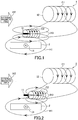
FIG. 1 is a diagram showing a current sensor according to a first embodiment of the present invention; -
FIG. 2 is a diagram showing a current sensor according to a second embodiment of the present invention; and -
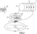
FIG. 3 is a diagram showing a current sensor according to a third embodiment of the present invention; - In the following, a first embodiment of the present invention will be explained with reference to
FIG. 1 . Acurrent sensor 1 shown inFIG. 1 is a sensor configured to detect a current I1 flowing through a bus bar (an object to be measured) 2. In the drawing, the current I1 flows in thebus bar 2 in a direction perpendicular to a plane of a paper, and a magnetic field H1 is generated due to this current I1. The magnetic field H1 is generated around an axis corresponding to the direction in which the current I1 flows (i.e., the direction perpendicular to the plane of the paper). - The
current sensor 1 includes a magneticfield detecting element 11, a first coil C1 and a second coil C2. The magneticfield detecting element 11 is an element that outputs a voltage according to a magnitude of a magnetic field, and is arranged around the bus bar 2 (within a range into which the magnetic field H1 is inputted or penetrates). - The output of the magnetic
field detecting element 11 may be affected by an external magnetic field H2 (i.e., a magnetic field other than the magnetic field H1 generated by the current I1 flowing through the bus bar 2), possibly lowering the detection accuracy. Thus, in this embodiment, in order to cancel the effect of the external magnetic field H2, the first coil C1 and the second coil C2 are arranged around the magneticfield detecting element 11. - The first coil C1 is arranged around the magnetic
field detecting element 11, and an induced current I2 is generated due to a change (variation) in the external magnetic field H2 generated around the magneticfield detecting element 11. The first coil C1 is wound in a spiral fashion, and a central axis of the first coil C1 is arranged parallel to a direction of the magnetic field H1 generated at the arrangement position of the magneticfield detecting element 11. - In this embodiment, in the arrangement position of the magnetic
field detecting element 11, the direction of the magnetic field H1 is parallel to a right-left direction with respect to the plane of the paper, thus the first coil C1 is arranged such that its central axis is parallel to the right-left direction. As such, when the external magnetic field H2 in the right-left direction is generated, the induced current I2 according to a magnitude of the change in the external magnetic field H2 is generated in the first coil C1. - The second coil C2 is connected to the first coil C1 and is configured to generate, upon the flow of the induced
current 12, a magnetic field H3 that cancels the external magnetic field H2 generated around the magneticfield detecting element 11. The second coil C2 is wound in a spiral fashion, and both ends of the second coil C2 are connected to both ends of the first coil C1. As such, the induced current I2 generated in the first coil C1 flows through the second coil C2. - The magnetic
field detecting element 11 is arranged in vicinity of the second coil C2. In the first embodiment, the magneticfield detecting element 11 is arranged inside this second coil C2. Thus, the second coil C2 is arranged so as to generate, upon the flow of the inducedcurrent 12, the magnetic field H3 opposite of the external magnetic field H2, inside the second coil C2. That is, the first coil C1 is opposite in the winding direction to the second coil C2. In addition, a diameter or number of turns of the first and second coils C1, C2 are adjusted such that a magnitude of the magnetic field H3 and a magnitude of the external magnetic field H2 are equal. - Next, a principle of current detection of the
current sensor 1 configured as described above will be explained. When the current I1 flows through thebus bar 2, the magnetic field H1 according to a magnitude of the current I1 is generated around thebus bar 2. In this embodiment, the current I1 flows in the direction perpendicular to the plane of the paper from a front side to a back side. At this time, the magnetic field H1 is generated in a clockwise direction around thebus bar 2, and the magnetic field H1 heading from the left side to the right side is inputted to the magneticfield detecting element 11. - The following will explain a case where the external magnetic field H2 (alternate current) with a varying magnitude of the magnetic field and a varying direction (polarity) of the magnetic field are generated at this time. Now, when the external magnetic field H2 heading from the left side to the right side is generated, the induced current I2 is generated in the first coil C1 in the clockwise direction with respect to the central axis, as shown in
FIG. 1 . This generated induced current I2 flows through the second coil C2. - The induced current I2 flowing through the second coil C2 flows in a counterclockwise direction with respect to the central axis, contrary to the first coil C1. Then, due to the flow of the induced
current 12, the magnetic field H3 in the direction from the right side to the left side, i.e., in the direction opposite to the direction of the external magnetic field H2, is generated inside the second coil C2. The diameter and the number of turns of the first and second coils C1, C2 are adjusted such that this magnetic field H3 has the same magnitude with the external magnetic field H2. Consequently, the external magnetic field H2 around the magneticfield detecting element 11 is cancelled by the magnetic field H3, thereby the effect of the external magnetic field H2 can be cancelled. - Further, when the external magnetic field H2 varies and increases, the induced current I2 increases, and the magnetic field H3 increases. When the external magnetic field H2 varies and decreases, the induced current I2 decreases, and the magnetic field H3 decreases. Thus, the magnetic field H3 having the same magnitude as the external magnetic field H2 is always generated inside the second coil C2, thereby the effect of the varying external magnetic field H2 can be cancelled.
- On the other hand, when the external magnetic field H2 heading from the right side to the left side is generated, the induced current I2 is generated in the first coil C1 in the counterclockwise direction with respect to the central axis. This generated induced current I2 flows through the second coil C2. The induced current I2 flowing through the second coil C2 flows in the clockwise direction with respect to the central axis, contrary to the first coil C1. Then, due to the flow of the induced
current 12, the magnetic field H3 in the direction from the left side to the right side, i.e., in the direction opposite to the direction of the external magnetic field H2, is generated inside the second coil C2. Consequently, even if the direction of the external magnetic field H2 varies, the external magnetic field H2 around the magneticfield detecting element 11 is cancelled by the magnetic field H3, thereby the effect of the external magnetic field H2 can be cancelled. - According to the first embodiment described above, the
current sensor 1 configured to cancel the effect of the varying external magnetic field H2 without use of a shield or a plurality of magnetic field detecting elements as described above can be provided at a low cost. Further, a control system such as the one for a calculating process is not required, and also, there is no time delay from the generation of the external magnetic field H2 until the cancelling. - Next, a second embodiment of the present invention will be explained with reference to
FIG. 2 . The second embodiment differs from the first embodiment mainly in the arrangement position of the magneticfield detecting element 11. In the second embodiment, the magneticfield detecting element 11 is arranged outside the second coil C2 along a magnetic field generated by the second coil C2. Further, in the second embodiment, the magneticfield detecting element 11 and the second coil C2 are opposedly-arranged along the axial direction of the second coil C2 with a space between each other. It is noted that the direction of the magnetic field H3 in the arrangement position of the second embodiment shown inFIG. 2 is the same as the direction of the magnetic field H3 inside the second coil C2. - As in the case with the first embodiment, in this case the induced current I2 is generated in the first coil C1 upon the change in the external magnetic field H2, and this induced current I2 flows through the second coil C2. Then , due to the induced current I2 flowing through the second coil C2, the magnetic field H3 having the opposite direction to the external magnetic field H2 is generated at the arrangement position of the magnetic
field detecting element 11, thereby cancelling the external magnetic field H2. - Next, a third embodiment of the present invention will be explained with reference to
FIG. 3 . The third embodiment differs from the first embodiment mainly in the arrangement position of the magneticfield detecting element 11. In the third embodiment, the magneticfield detecting element 11 is arranged outside the second coil C2 along a magnetic field generated by the second coil C2. Further, in the third embodiment, the magneticfield detecting element 11 and the second coil C2 are opposedly-arranged along a radial direction of the second coil C2 with a space between each other. It is noted that the direction of the magnetic field H3 in the arrangement position of the third embodiment shown inFIG. 3 is opposite to the direction of the magnetic field H3 inside the second coil C2. - Thus, unlike the first and second embodiments, in the third embodiment, the winding direction is the same in the first and second coils C1, C2.
- Next, a principle of current detection of the
current sensor 1 configured as described above will be explained. When the current I1 flows through thebus bar 2, the magnetic field H1 according to a magnitude of the current I1 is generated around thebus bar 2. In this embodiment, the current I1 flows in the direction perpendicular to the plane of the paper from the front side to the back side. At this time, the magnetic field H1 is generated in the clockwise direction around thebus bar 2, and the magnetic field H1 heading from the left side to the right side is inputted to the magneticfield detecting element 11. - The following will explain a case where the external magnetic field H2 (alternate current) with a varying magnitude of the magnetic field and a varying direction (polarity) of the magnetic field are generated at this time. Now, when the external magnetic field H2 heading from the left side to the right side is generated, the induced current I2 is generated in the first coil C1 in the clockwise direction with respect to the central axis, as shown in
FIG. 3 . This generated induced current I2 flows through the second coil C2. - In the third embodiment, the induced current I2 flowing through the second coil C2 flows in the clockwise direction with respect to the central axis, as in the first coil C1. Then, due to the induced current I2 flowing through the second coil C2, the magnetic field H3 in the direction from the right side to the left side, i.e., in the direction opposite to the direction of the external magnetic field H2, is generated at the arrangement position of the magnetic
field detecting element 11. Consequently, the external magnetic field H2 around the magneticfield detecting element 11 is cancelled by the magnetic field H3, thereby the effect of the external magnetic field H2 can be cancelled. - On the other hand, when the external magnetic field H2 heading from the right side to the left side is generated, the induced current I2 is generated in the first coil C1 in the counterclockwise direction with respect to the central axis. This generated induced current I2 flows through the second coil C2. The induced current I2 flowing through the second coil C2 flows in the counterclockwise direction with respect to the central axis, as in the first coil C1. Then, due to the induced current I2 flowing through the second coil C2, the magnetic field H3 in the direction from the left side to the right side, i.e., in the direction opposite to the direction of the external magnetic field H2, is generated at the arrangement position of the magnetic
field detecting element 11. Consequently, even if the direction of the external magnetic field H2 varies, the external magnetic field H2 around the magneticfield detecting element 11 is cancelled by the magnetic field H3, thereby the effect of the external magnetic field H2 can be cancelled. - The present invention is not limited to the above-described embodiments. That is, various modifications can be made and implemented without departing from the scope of the present invention.
-
- 1
- current sensor
- 2
- bus bar (object to be measured)
- C1
- first coil
- C2
- second coil
- 11
- magnetic field detecting element
- I2
- induced current
- I1
- current
Claims (4)
- A current sensor comprising:a magnetic field detecting element configured to detect a magnetic field generated by a current flowing through an object to be measured;a first coil in which an induced current is generated due to an external magnetic field varying around the magnetic field detecting element; anda second coil connected to the first coil and configured to generate, upon flow of the induced current, a magnetic field that cancels the external magnetic field varying around the magnetic field detecting element.
- The current sensor according to claim 1, wherein
the magnetic field detecting element is arranged in vicinity of the second coil. - The current sensor according to claim 1, wherein
the magnetic field detecting element is arranged inside the second coil. - The current sensor according to claim 1, wherein
the magnetic field detecting element is arranged outside the second coil along the magnetic field generated by the second coil.
Applications Claiming Priority (1)
| Application Number | Priority Date | Filing Date | Title |
|---|---|---|---|
| JP2018143653A JP2020020629A (en) | 2018-07-31 | 2018-07-31 | Current sensor |
Publications (1)
| Publication Number | Publication Date |
|---|---|
| EP3605114A1 true EP3605114A1 (en) | 2020-02-05 |
Family
ID=67513392
Family Applications (1)
| Application Number | Title | Priority Date | Filing Date |
|---|---|---|---|
| EP19189121.7A Withdrawn EP3605114A1 (en) | 2018-07-31 | 2019-07-30 | Current sensor |
Country Status (4)
| Country | Link |
|---|---|
| US (1) | US20200041581A1 (en) |
| EP (1) | EP3605114A1 (en) |
| JP (1) | JP2020020629A (en) |
| CN (1) | CN110780102A (en) |
Citations (6)
| Publication number | Priority date | Publication date | Assignee | Title |
|---|---|---|---|---|
| JPH0525369U (en) | 1991-09-12 | 1993-04-02 | 株式会社トーキン | Current sensor |
| JP2002243766A (en) | 2001-02-16 | 2002-08-28 | Fuji Electric Co Ltd | Current sensor |
| JP2005221342A (en) * | 2004-02-04 | 2005-08-18 | Mitsubishi Electric Corp | Coil type current sensor |
| JP2010048755A (en) * | 2008-08-25 | 2010-03-04 | Fuji Electric Systems Co Ltd | Current sensor and voltmeter |
| US9030197B1 (en) * | 2012-03-23 | 2015-05-12 | Ohio Semitronics Inc. | Active compensation for ambient, external magnetic fields penetrating closed loop magnetic cores particularly for a fluxgate current sensor |
| JP2017122671A (en) * | 2016-01-08 | 2017-07-13 | Necプラットフォームズ株式会社 | Current detector and current detection method |
-
2018
- 2018-07-31 JP JP2018143653A patent/JP2020020629A/en not_active Abandoned
-
2019
- 2019-07-10 US US16/507,334 patent/US20200041581A1/en not_active Abandoned
- 2019-07-25 CN CN201910677691.1A patent/CN110780102A/en not_active Withdrawn
- 2019-07-30 EP EP19189121.7A patent/EP3605114A1/en not_active Withdrawn
Patent Citations (6)
| Publication number | Priority date | Publication date | Assignee | Title |
|---|---|---|---|---|
| JPH0525369U (en) | 1991-09-12 | 1993-04-02 | 株式会社トーキン | Current sensor |
| JP2002243766A (en) | 2001-02-16 | 2002-08-28 | Fuji Electric Co Ltd | Current sensor |
| JP2005221342A (en) * | 2004-02-04 | 2005-08-18 | Mitsubishi Electric Corp | Coil type current sensor |
| JP2010048755A (en) * | 2008-08-25 | 2010-03-04 | Fuji Electric Systems Co Ltd | Current sensor and voltmeter |
| US9030197B1 (en) * | 2012-03-23 | 2015-05-12 | Ohio Semitronics Inc. | Active compensation for ambient, external magnetic fields penetrating closed loop magnetic cores particularly for a fluxgate current sensor |
| JP2017122671A (en) * | 2016-01-08 | 2017-07-13 | Necプラットフォームズ株式会社 | Current detector and current detection method |
Non-Patent Citations (2)
| Title |
|---|
| SLAWOMIR TUMANSKI: "REVIEW ARTICLE; Induction coil sensors-a review", MEASUREMENT SCIENCE AND TECHNOLOGY, IOP, BRISTOL, GB, vol. 18, no. 3, 1 March 2007 (2007-03-01), pages R31 - R46, XP020118574, ISSN: 0957-0233, DOI: 10.1088/0957-0233/18/3/R01 * |
| YANG YONG ET AL: "Analysis and Test of a Zero-Flux Current Sensor to Be Used in ITER", JOURNAL OF FUSION ENERGY, PLENUM PUB.CORPORATION. NEW YORK, US, vol. 34, no. 3, 12 December 2014 (2014-12-12), pages 463 - 468, XP035499053, ISSN: 0164-0313, [retrieved on 20141212], DOI: 10.1007/S10894-014-9820-4 * |
Also Published As
| Publication number | Publication date |
|---|---|
| JP2020020629A (en) | 2020-02-06 |
| CN110780102A (en) | 2020-02-11 |
| US20200041581A1 (en) | 2020-02-06 |
Similar Documents
| Publication | Publication Date | Title |
|---|---|---|
| US9677913B2 (en) | Inductive displacement sensor | |
| CN113447699B (en) | Tunnel magnetoresistance annular array current sensor and current measuring method | |
| CA2733431C (en) | Multi-axis fluxgate magnetic sensor | |
| AU2017219153B2 (en) | Rogowski coil type sensor for measuring current, measuring device and electrical circuit breaker including such a sensor, and method for winding such a sensor | |
| US20200355758A1 (en) | Magnetic sensor | |
| EP2916111B1 (en) | Thermal flow meter | |
| CN108880525B (en) | Proximity sensor and method performed in proximity sensor | |
| EP3709320B1 (en) | Current transformer | |
| EP3779517A1 (en) | Detection coil, detection device, and detection system | |
| US20240418749A1 (en) | Magnetic sensor apparatus | |
| US9952064B2 (en) | Transformer position sensor with shorted coil | |
| JP2018115929A (en) | Electric current sensor signal correction method, and electric current sensor | |
| CN112362941A (en) | Annular current transformer and method for measuring current by using same | |
| CN112946358A (en) | Temperature drift error compensation unit and method for measuring current | |
| JP6298581B2 (en) | Current detection device and substation equipment provided with the same | |
| CN106441081A (en) | Rotor-winding-free time-grating angular displacement sensor | |
| ITMI992739A1 (en) | CURRENT MEASURING DEVICE FOR LOW VOLTAGE POWER SWITCHES | |
| US20200041581A1 (en) | Current sensor | |
| CN114566949A (en) | Sensitive impedance-based string protection for multi-string and multi-stage capacitor banks | |
| JP6327411B1 (en) | Ground fault location system, ground fault location method | |
| EP4303591A1 (en) | Current sensor | |
| US20240288514A1 (en) | Magnetic detection device | |
| JP6396768B2 (en) | CURRENT MEASUREMENT DEVICE, CURRENT MEASUREMENT SYSTEM, CURRENT MEASUREMENT METHOD, AND CURRENT MEASUREMENT PROGRAM | |
| JP7415867B2 (en) | Magnetic balanced current sensor | |
| KR102350709B1 (en) | Current Measurement Apparatus |
Legal Events
| Date | Code | Title | Description |
|---|---|---|---|
| PUAI | Public reference made under article 153(3) epc to a published international application that has entered the european phase |
Free format text: ORIGINAL CODE: 0009012 |
|
| 17P | Request for examination filed |
Effective date: 20190730 |
|
| AK | Designated contracting states |
Kind code of ref document: A1 Designated state(s): AL AT BE BG CH CY CZ DE DK EE ES FI FR GB GR HR HU IE IS IT LI LT LU LV MC MK MT NL NO PL PT RO RS SE SI SK SM TR |
|
| AX | Request for extension of the european patent |
Extension state: BA ME |
|
| STAA | Information on the status of an ep patent application or granted ep patent |
Free format text: STATUS: THE APPLICATION IS DEEMED TO BE WITHDRAWN |
|
| 18D | Application deemed to be withdrawn |
Effective date: 20200806 |