EP3605012B1 - Laser scanning method, assembly and underwater vehicle comprising corresponding assembly - Google Patents
Laser scanning method, assembly and underwater vehicle comprising corresponding assembly Download PDFInfo
- Publication number
- EP3605012B1 EP3605012B1 EP18727337.0A EP18727337A EP3605012B1 EP 3605012 B1 EP3605012 B1 EP 3605012B1 EP 18727337 A EP18727337 A EP 18727337A EP 3605012 B1 EP3605012 B1 EP 3605012B1
- Authority
- EP
- European Patent Office
- Prior art keywords
- fan
- laser
- light
- scanning area
- light receiver
- Prior art date
- Legal status (The legal status is an assumption and is not a legal conclusion. Google has not performed a legal analysis and makes no representation as to the accuracy of the status listed.)
- Active
Links
- 238000000034 method Methods 0.000 title claims description 16
- 238000012545 processing Methods 0.000 claims description 15
- 238000012512 characterization method Methods 0.000 claims description 13
- 230000001131 transforming effect Effects 0.000 claims description 6
- 230000001360 synchronised effect Effects 0.000 claims description 3
- XLYOFNOQVPJJNP-UHFFFAOYSA-N water Substances O XLYOFNOQVPJJNP-UHFFFAOYSA-N 0.000 description 11
- 230000000712 assembly Effects 0.000 description 3
- 238000000429 assembly Methods 0.000 description 3
- 238000013507 mapping Methods 0.000 description 3
- 238000005259 measurement Methods 0.000 description 3
- 230000000694 effects Effects 0.000 description 2
- 238000003384 imaging method Methods 0.000 description 2
- 238000003754 machining Methods 0.000 description 2
- 238000004519 manufacturing process Methods 0.000 description 2
- 239000013307 optical fiber Substances 0.000 description 2
- 230000002238 attenuated effect Effects 0.000 description 1
- 230000000593 degrading effect Effects 0.000 description 1
- 230000001419 dependent effect Effects 0.000 description 1
- 238000010586 diagram Methods 0.000 description 1
- 239000011521 glass Substances 0.000 description 1
- 238000012423 maintenance Methods 0.000 description 1
- 229910021421 monocrystalline silicon Inorganic materials 0.000 description 1
- 230000001681 protective effect Effects 0.000 description 1
- 239000004065 semiconductor Substances 0.000 description 1
- 239000007787 solid Substances 0.000 description 1
Images


Classifications
-
- G—PHYSICS
- G01—MEASURING; TESTING
- G01B—MEASURING LENGTH, THICKNESS OR SIMILAR LINEAR DIMENSIONS; MEASURING ANGLES; MEASURING AREAS; MEASURING IRREGULARITIES OF SURFACES OR CONTOURS
- G01B11/00—Measuring arrangements characterised by the use of optical techniques
- G01B11/24—Measuring arrangements characterised by the use of optical techniques for measuring contours or curvatures
- G01B11/25—Measuring arrangements characterised by the use of optical techniques for measuring contours or curvatures by projecting a pattern, e.g. one or more lines, moiré fringes on the object
- G01B11/2513—Measuring arrangements characterised by the use of optical techniques for measuring contours or curvatures by projecting a pattern, e.g. one or more lines, moiré fringes on the object with several lines being projected in more than one direction, e.g. grids, patterns
-
- G—PHYSICS
- G01—MEASURING; TESTING
- G01B—MEASURING LENGTH, THICKNESS OR SIMILAR LINEAR DIMENSIONS; MEASURING ANGLES; MEASURING AREAS; MEASURING IRREGULARITIES OF SURFACES OR CONTOURS
- G01B11/00—Measuring arrangements characterised by the use of optical techniques
- G01B11/24—Measuring arrangements characterised by the use of optical techniques for measuring contours or curvatures
- G01B11/25—Measuring arrangements characterised by the use of optical techniques for measuring contours or curvatures by projecting a pattern, e.g. one or more lines, moiré fringes on the object
- G01B11/2518—Projection by scanning of the object
-
- G—PHYSICS
- G01—MEASURING; TESTING
- G01S—RADIO DIRECTION-FINDING; RADIO NAVIGATION; DETERMINING DISTANCE OR VELOCITY BY USE OF RADIO WAVES; LOCATING OR PRESENCE-DETECTING BY USE OF THE REFLECTION OR RERADIATION OF RADIO WAVES; ANALOGOUS ARRANGEMENTS USING OTHER WAVES
- G01S17/00—Systems using the reflection or reradiation of electromagnetic waves other than radio waves, e.g. lidar systems
- G01S17/02—Systems using the reflection of electromagnetic waves other than radio waves
- G01S17/06—Systems determining position data of a target
- G01S17/46—Indirect determination of position data
-
- G—PHYSICS
- G01—MEASURING; TESTING
- G01S—RADIO DIRECTION-FINDING; RADIO NAVIGATION; DETERMINING DISTANCE OR VELOCITY BY USE OF RADIO WAVES; LOCATING OR PRESENCE-DETECTING BY USE OF THE REFLECTION OR RERADIATION OF RADIO WAVES; ANALOGOUS ARRANGEMENTS USING OTHER WAVES
- G01S17/00—Systems using the reflection or reradiation of electromagnetic waves other than radio waves, e.g. lidar systems
- G01S17/88—Lidar systems specially adapted for specific applications
- G01S17/89—Lidar systems specially adapted for specific applications for mapping or imaging
-
- G—PHYSICS
- G01—MEASURING; TESTING
- G01S—RADIO DIRECTION-FINDING; RADIO NAVIGATION; DETERMINING DISTANCE OR VELOCITY BY USE OF RADIO WAVES; LOCATING OR PRESENCE-DETECTING BY USE OF THE REFLECTION OR RERADIATION OF RADIO WAVES; ANALOGOUS ARRANGEMENTS USING OTHER WAVES
- G01S7/00—Details of systems according to groups G01S13/00, G01S15/00, G01S17/00
- G01S7/48—Details of systems according to groups G01S13/00, G01S15/00, G01S17/00 of systems according to group G01S17/00
- G01S7/481—Constructional features, e.g. arrangements of optical elements
- G01S7/4814—Constructional features, e.g. arrangements of optical elements of transmitters alone
-
- G—PHYSICS
- G01—MEASURING; TESTING
- G01S—RADIO DIRECTION-FINDING; RADIO NAVIGATION; DETERMINING DISTANCE OR VELOCITY BY USE OF RADIO WAVES; LOCATING OR PRESENCE-DETECTING BY USE OF THE REFLECTION OR RERADIATION OF RADIO WAVES; ANALOGOUS ARRANGEMENTS USING OTHER WAVES
- G01S7/00—Details of systems according to groups G01S13/00, G01S15/00, G01S17/00
- G01S7/48—Details of systems according to groups G01S13/00, G01S15/00, G01S17/00 of systems according to group G01S17/00
- G01S7/481—Constructional features, e.g. arrangements of optical elements
- G01S7/4817—Constructional features, e.g. arrangements of optical elements relating to scanning
-
- B—PERFORMING OPERATIONS; TRANSPORTING
- B63—SHIPS OR OTHER WATERBORNE VESSELS; RELATED EQUIPMENT
- B63G—OFFENSIVE OR DEFENSIVE ARRANGEMENTS ON VESSELS; MINE-LAYING; MINE-SWEEPING; SUBMARINES; AIRCRAFT CARRIERS
- B63G8/00—Underwater vessels, e.g. submarines; Equipment specially adapted therefor
-
- G—PHYSICS
- G01—MEASURING; TESTING
- G01C—MEASURING DISTANCES, LEVELS OR BEARINGS; SURVEYING; NAVIGATION; GYROSCOPIC INSTRUMENTS; PHOTOGRAMMETRY OR VIDEOGRAMMETRY
- G01C11/00—Photogrammetry or videogrammetry, e.g. stereogrammetry; Photographic surveying
- G01C11/04—Interpretation of pictures
- G01C11/30—Interpretation of pictures by triangulation
Definitions
- the invention relates to a laser scanning assembly for obtaining a geometric characterization of the shape of a surface based on the principle of triangulation comprising: a laser light emitter for emitting a laser light beam, first diffraction means for transforming said laser light beam into a planar fan configuration arranged downstream of said laser light emitter, first light redirecting means arranged downstream of said laser light emitter for receiving and redirecting said laser light beam and projecting it onto said surface that must be characterized, a light receiver arranged with respect to said surface and with respect to said first redirecting means such that said light receiver captures a scanning area corresponding to an area of said surface that must be characterized including said fan projected onto said surface, and control means functionally associated with said light emitter and said light receiver for synchronizing the joint operation of said light emitter and said light receiver, and said first redirecting means and said light receiver being separated by a known predetermined distance defining a constant baseline between both, and said fan forming, once it is redirected, a first angle with respect to said baseline, and
- the invention also relates to a vehicle incorporating said laser scanning assembly for characterizing a surface.
- the invention also relates to a laser scanning method for obtaining a characterization of the shape of a surface comprising the steps of emitting a laser light beam through a laser light emitter, transforming said laser light beam into a planar fan configuration through first diffraction means arranged downstream of said laser light emitter, receiving said laser beam and redirecting it to project it onto said surface that must be characterized through first light redirecting means arranged downstream of said laser light emitter, capturing a scanning area of said surface that must be characterized through a light receiver arranged with respect to said light emitter, said area containing said fan projected onto said surface, and synchronizing the emission of said fan light emitter and the capture by said light receiver through control means functionally associated with said light emitter and said light receiver, said first redirecting means and said light receiver being separated by a known predetermined distance defining a baseline between both, and said fan forming, once it is redirected, a first angle with respect to said baseline, and once it is reflected by said surface, a second angle with respect to said baseline
- Laser scanning assemblies are known in the state of the art. These assemblies make it easier to obtain data for generating one or more three-dimensional point clouds that geometrically describe the surface that must be characterized.
- Document US 2012/0062963 A1 discloses a laser scanning assembly including primarily an emitter, a receiver, and a central control.
- the emitter is a laser light emitter including means for configuring the laser light in a fan configuration.
- the fan is projected onto the surface that must be characterized.
- the receiver which is usually a camera, receives this surface-reflected light that must be characterized.
- the control is associated with the emitter and the receiver and is in charge of controlling the emission and reception of the laser light. Furthermore, the control also moves the emitter and receiver together so as to obtain the images which later allow generating the point clouds that characterize the surface.
- US 2012/0062963 A1 discloses a second scanning assembly comprising two light receiver subassemblies and a laser light emitter subassembly arranged between the light receiver subassemblies.
- the light emitter again has means for converting the laser spot light into a fan configuration.
- the emitter subassembly can be moved with respect to the light receiver subassemblies.
- Document US 2007/285672 A1 discloses an operation of projecting slit light onto an object to be measured and receiving light reflected thereon, and an operation of acquiring a two-dimensional image concerning the object to be measured are repeated a certain number of times by changing a focal length.
- An imaging contrast is calculated with respect to each of areas on the two-dimensional images acquired at the different focal lengths.
- a high contrast area where the imaging contrast exceeds a predetermined threshold value is extracted with respect to each of the two-dimensional images acquired at the different focal lengths.
- Distance information concerning the respective areas is acquired by performing triangulation with respect to each of the high contrast areas.
- Position adjustment of measurement dimensions is performed in such a manner that the areas are included in the measurement dimensions having the predetermined measurement depth, based on the distance information.
- the assembly according to the invention has a number of advantages with respect to the assemblies known in the state of the art.
- the light redirecting means being assembled so as to be rotational about a fixed shaft with respect to the emitter and the receiver, the need to move both the emitter and the receiver during scanning is eliminated.
- the mass that must be moved to enable carrying out the scanning is thereby reduced, and the speed of projecting laser light at different points of the surface to be characterized is accordingly increased, since system inertias are minimal.
- Preferred redirecting means are a galvanometric mirror, for example.
- the galvanometric mirror can be formed by any reflective surface capable of withstanding the effect of the incident laser without degrading.
- the fact that the receiver incorporates first processing means allows considerably reducing the data that is transmitted from said light receiver to said central control and used for finally obtaining the point cloud.
- the combination of both features allows greatly increasing in speed since the laser light can be moved at a high speed to scan the surface to be characterized.
- the reception means only process the indispensable points of each image which they receive from the scanned surface to characterize its geometry.
- the invention further includes a number of preferred features that are object of the dependent claims and the utility of which will be highlighted hereinafter in the detailed description of an embodiment of the invention.
- said first diffraction means are arranged between said laser light emitter and said first light redirecting means, such that said laser light beam is first transformed into a planar fan configuration, and it is then redirected by said redirecting means to project said fan onto said surface that must be characterized.
- a cylindrical lens or a standard Powell lens adapted to the characteristics of the laser without the need for high assembly machining and assembly precisions can be used.
- said light receiver comprises a region of interest corresponding to a part of said scanning area, said region of interest being mobile in said scanning area controlled by said control means, depending on the angular position of said first redirecting means, such that said region of interest is displaced in said scanning area to contain the instantaneous position of said fan in said scanning area.
- This region of interest considerably reduces the scanning area that must be processed through the first processing means of the receiver, which again favors the increase in speed of the assembly.
- said scanning area is a parallelogram having right angles with a predetermined base and height
- said region of interest is a parallelogram having right angles.
- the light capturing sensor of a camera and which is projected onto all or part of the surface to be characterized, this projection does not have to be rectangular.
- said region of interest occupies all of said base or said height of said scanning area, i.e., the region of interest occupies the entire height or the entire base of said parallelogram.
- the region of interest only occupies a part of the other magnitude, i.e., if it occupies the entire height, then it will only occupy part of the base of the scanning area. Control of the region of interest with respect to the area of incidence is thereby simplified, since it must only be moved in one direction.
- the light emitter, said redirecting means, and said light receiver are encapsulated in at least one housing, and said at least one housing comprises an emitting window and a receiving window, said redirecting means being opposite said emitting window to project said planar fan onto said surface, whereas said light receiver is opposite said receiving window to capture said scanning area.
- Another relevant problem consists of optimizing the scanning assembly in order to work in media other than air, and particularly submerged in water.
- said housing is watertight and said laser is green or blue.
- the green or blue laser is attenuated to a lesser extent under water than other types of laser and therefore is projected a greater distance.
- it is preferred for the laser to be green since despite experiencing greater attenuation than a blue laser does, a green laser experiences less backscattering than a blue laser does.
- planar fan In conditions of a single projection medium, i.e., projection into the air without a change of medium, the planar fan is projected onto the surface as a straight line. This does not occur in cases where there is a change of medium, for example, air-window-water.
- the invention also relates to a vehicle incorporating a laser scanning assembly according to the invention.
- Vehicles of this type equipped in this manner have great operating autonomy, since they are capable of determining what their surrounding environment is like.
- the device is an underwater vehicle.
- the invention considers the problem of reducing human risks in underwater operations.
- the underwater vehicle is a remotely operated or autonomous vehicle.
- the invention also relates to a method that allows improving the speed and definition of the scanning of the surface to be characterized.
- said first diffraction means are arranged between said laser light emitter and said first light redirecting means such that said laser light beam is first transformed into a planar fan configuration, and it is then redirected by said redirecting means to project said fan onto said surface that must be characterized.
- the method comprises the step of applying a region of interest on a part of said scanning area, said region of interest being mobile in said scanning area controlled said control means, depending on the angular position of said first redirecting means, such that said region of interest is displaced in said scanning area to contain the instantaneous position of said fan in said scanning area.
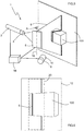
- Figures 1 and 2 very schematically show a first embodiment of the laser scanning assembly 1 according to the invention for obtaining a characterization of the shape of a surface 100.
- the assembly 1 comprises a laser light emitter 2, a light receiver 10, and control means 14 functionally associated with the light emitter 2 and the light receiver 10 and the redirecting means 8 and in charge of synchronizing the operation thereof.
- the light emitter 2 is a laser spot light source, i.e., a beam which is projected onto a surface in the form of a point.
- the laser can be any type of laser, such as a semiconductor-based or solid state laser, and a laser of any wavelength, for example.
- the light emitter 2 has diffraction means 4 transforming the laser spot light beam into a planar fan configuration 6.
- the diffraction means 4 are, for example, a cylindrical lens or a Powell lens.
- the light emitter 2 and the diffraction means 4 do not necessarily have to form one unit.
- the diffraction means 4 can be aligned with but somewhat separated from the light emitter 2.
- the light emitter 2 can be separated from the diffraction means 4.
- both elements are connected to one another through light guiding means 30, such as an optical fiber, for example. This allows achieving more compact constructive configurations.
- first light redirecting means 8 are provided downstream of the light emitter 2. Accordingly, in this embodiment the diffraction means 4 are located between the light emitter 2 and the light redirecting means 8. This greatly simplifies the assembly, and the lens of the diffraction means 4 is easier to manufacture.
- the light redirecting means 8 are a galvanometric mirror manufactured, for example, from monocrystalline silicon with concentrations greater than 95%. In operation, the galvanometric mirror is oriented to project the laser beam configured like a fan 6 coming from the diffraction means 4 onto the surface 100 to be characterized.
- the light emitter 2 and the incident beam redirecting means 8 are encapsulated in a first housing 22a.
- This housing 22a has an emitting window 24.
- the galvanometric mirror is opposite this emitting window 24 to receive the laser light fan 6 from the light emitter 2, redirect it, and project it onto the surface 100 that must be characterized.
- the planar fan 6 is projected onto the surface as a straight line. This does not occur in cases where there is a change of medium, for example, air-emitting window 24-water.
- the assembly 1 also has a light receiver 10 arranged such that it is oriented towards the surface 100 that must be characterized and oriented with respect to the first redirecting means 8 such that it can capture a scanning area 12 of the surface 100 onto which the fan 6 is projected.
- the light receiver 10 can be a camera capable of identifying the pixels illuminated by the reflection of the laser light coming from the surface that must be characterized.
- the light receiver 10 is also assembled within a second protective housing 22b.
- the housing 22b of the light receiver 10 comprises a receiving window 26.
- the receiving window 26 is large enough so that when the light receiver 10 is opposite this receiving window 26, it can capture the mentioned scanning area 12, without being covered by the walls the edges of the receiving window 26.
- the orientation is such that for any angular position the first redirecting means 8, the fan 6 projected onto the surface 100 is contained within the scanning area 12.
- the first redirecting means 8 and the light receiver 10 are separated by a predetermined, known and constant linear distance. This linear distance defines a baseline 28 between both elements of the assembly 1. As can be seen in the drawings, once the fan 6 is redirected it forms a first angle ⁇ with respect to said baseline 28, and once the fan 6 is reflected by said surface 10 it forms a second angle ⁇ with respect to said baseline 28.
- the assembly 1 also has control means 14 which are functionally associated with the light emitter and the light receiver 2, 10 as well as with the redirecting elements 8 through cables for synchronizing the emission of the laser beam by the light emitter 2 with the angular position of the redirecting means 8, with the capture of the scanning area 12 by the light receiver 10.
- the light receiver 10 captures an image for each position of the fan 6.
- all the elements of the assembly 1 according to the invention can optionally be arranged in a single housing 22a with individual emitting and receiving windows (see Figures 8 and 9 ) or with a single window for the two functions.
- the housing 22a it is also preferred for the housing 22a to be watertight. This allows using the scanning assembly 1 under water.
- This solution can be applied, for example, to a remotely operated underwater vehicle, better known in the art as ROV, for Remotely Operated Vehicle, or an Autonomous Underwater Vehicle, known as AUV.
- the laser that is used is preferably a green or blue.
- a blue laser is preferred in the case of clear or slightly cloudy water, whereas a green laser is preferred when the water is cloudy.
- the invention provides that the first redirecting means 8 are assembled so as to be rotational about the fixed shaft 16 with respect to the emitter and the light receiver 2, 10.
- the rotation with respect to the emitter and the light receiver 2, 10 is carried out with respect to the vertical shaft, which would protrude from the plane of Figures 1 and 2 , and the rotation is indicated in the drawings with the doubleheaded arrow A.
- the rotation of the first redirecting means 8 is controlled by the control means 14.
- the fan 6 is thereby displaced by rotating the first redirecting means within the scanning area 12 along a plurality of different instantaneous positions P1, P2. This rotation to move the fan is synchronized with the emission of the fan 6 by the light emitter 2 and the capture of the scanning area by the light receiver 10, with the subsequent determination of the illuminated points.
- the light receiver 10 comprises its own first processing means 18, i.e., integrated in the light receiver 10 itself.
- These processing means 18 allow at least distinguishing which points of said scanning area 12 are illuminated by said fan laser 6.
- the first processing means 18 are capable of discriminating which points or pixels of the image correspond to the reflection of the laser light and which points or pixels do not.
- the fan 6 When the fan 6 is projected onto instantaneous position P1, if the medium is constant, for example when the projection occurs only in the air, this projection is a straight line. If there is a change of medium, for example air-emitting window 24-water, then the fan 6 forms a curve with a curvature that increases as the angle of incidence of the fan 6 on the emitting window 24 increases.
- the light receiver 10 detects the reflection of this line of points in the scanning area 12.
- the assembly 1 can determine and characterize the surface 100 in this position P1 by defining a plurality of reference points. This process of triangulation can take place either in the central unit 14, or preferably in the processing means 18 themselves.
- the redirecting means 8 will preferably carry out an angular movement that is always in the same direction during the acquisition of said point cloud. The larger the number of instantaneous positions captured by the light receiver 10, determining the shape of the projection of the fan onto the surface 100, the greater the definition of the geometric characterization thereof will be.
- the volume of data that is to be managed afterwards for obtaining the point cloud is much smaller. This allows achieving a higher speed or increasing the level of definition of the characterized surface 100.
- the generation of the point cloud according to the invention can also be obtained using the first processing means 18. Nevertheless, in any of the embodiments of the invention this can alternatively be done in the centralized control means 14.
- the scanning assembly 1 of Figures 3 to 6 is essentially identical to that of Figures 1 and 2 , i.e., it likewise comprises a laser light emitter 2, first diffraction means 4 for transforming the laser light beam into a planar fan configuration 6, first redirecting means 8 assembled so as to be rotational about a fixed shaft, a light receiver 10 with its own processing means 18, and control means 14 in charge of controlling the light emitter and the light receiver 2, 10.
- the assembly 1 is not encapsulated.
- the arrangement of all the elements and their joint operation is substantially the same, and they allow putting the same laser scanning method 1 into practice for obtaining a characterization of the shape of a surface 100.
- the most significant difference consists of the light receiver 10 comprising a region of interest 20 corresponding to only a part of the scanning area 12.
- the light receiver 10 itself is capable of reducing the area explored by the laser within the scanning area 12 to also reduce the area that must be processed in order to determine the position of the points illuminated by the laser fan 6.
- the region of interest 20 is mobile in the scanning area 12, controlled by the control means 14 depending on the position of the redirecting means 18.
- control means 14 take into consideration the instantaneous angular position of the first redirecting means 8 in order to later displace the region of interest 20 in the scanning area 12 such that the curve the fan 6 forms on the surface 100 that must be characterized is contained within the region of interest 20 in each image captured by the light receiver 14.
- the region of interest 20 is smaller than the scanning area 12 that the light receiver 10 may potentially scan in each captured image.
- the scanning area 12 is a parallelogram having right angles with a predetermined base and height
- the region of interest 20 can be a parallelogram having right angles which is displaced within the scanning area 12, controlled by the control means 14, as can be seen in the drawings.
- the region of interest 20 should be displaced in both a first main direction of the scanning area and in the perpendicular direction.
- the region of interest 20 in this case is a parallelogram having right angles that occupies the entire height of the scanning area 12 and only a part of its width. This greatly simplifies the control of the position of the region of interest 20 with respect to the theoretical scanning area. In this embodiment, the region of interest 20 must only be displaced in the horizontal direction along the scanning area. Alternatively, the parallelogram of the region of interest could occupy the entire width of the scanning area 12 and only a part of the height, and it would accordingly be displaced along the height of the scanning area 12.
- the scanning assembly 1 has a number of applications, particularly when it is assembled in a vehicle and more particularly in an underwater vehicle that can be remotely operated (ROV) or that can be autonomous (AUV), among others.
- ROV remotely operated
- AUV autonomous
- underwater mapping can be carried out, or maintenance operations in underwater structures or other operations can be performed.
- the laser beam has to go through three different media: the air within the housing of the vehicle, the glass of the emitting window, and finally water.
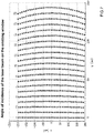
- the change of medium means that when the fan 6, which is theoretically planar, is projected onto the surface 100 to be characterized, it becomes deformed like a curve. This effect is depicted in Figure 7 . As can be seen, as the angle of incidence of the fan 6 on the emitting window increases, the fan curvature on the surface to be characterized increases.
- triangulation is performed between a beam that has illuminated the corresponding pixel of the camera that is the reflection of the fan 6 on the surface 100 with the fan characterized by a plane.
- the fan 6 is best characterized by an elliptical cone rather than by a plane. Therefore, triangulation in this case is performed by calculating the intersection of the light beam that has illuminated the pixel of the light receiver 10 with said light beam.
- FIGS 8 and 9 show a vehicle 32 according to the invention in which a scanning assembly 1 similar to those described up to this point is assembled.
- the vehicle 32 is preferably an underwater vehicle, and more particularly a remotely operated or autonomous underwater vehicle driven by propeller-type propulsion means 34.
- the vehicle 32 has a single first casing 22a containing the mentioned scanning assembly 1 therein.
- Vehicles of this type are suitable, for example, for mapping the seafloor.
- the vehicle has a scanning assembly 1 with features similar to those of the embodiment of Figure 1 . Accordingly, reference is made to the preceding paragraphs as regards these features and the scanning method.
- Figure 10 shows a schematic top plan view of a third embodiment of the scanning assembly 1 according to the invention.
- This scanning assembly 1 is virtually identical to the embodiment of Figures 1 and 2 . Accordingly, reference is made to the description of the embodiment of Figures 1 and 2 for the features not described below. Nevertheless, in this case the diffraction means 4 are arranged downstream of the redirecting means 8. The redirecting means thereby redirect a laser spot beam which later adopts the shape of a fan 6 after going through the diffraction means 4.
- the diffraction means 4 can also be a cylindrical lens or a Powell lens, but it is configured as a ring segment.
- the diffraction means 4 are formed directly on the emitting window 24 itself.
Description
- The invention relates to a laser scanning assembly for obtaining a geometric characterization of the shape of a surface based on the principle of triangulation comprising: a laser light emitter for emitting a laser light beam, first diffraction means for transforming said laser light beam into a planar fan configuration arranged downstream of said laser light emitter, first light redirecting means arranged downstream of said laser light emitter for receiving and redirecting said laser light beam and projecting it onto said surface that must be characterized, a light receiver arranged with respect to said surface and with respect to said first redirecting means such that said light receiver captures a scanning area corresponding to an area of said surface that must be characterized including said fan projected onto said surface, and control means functionally associated with said light emitter and said light receiver for synchronizing the joint operation of said light emitter and said light receiver, and said first redirecting means and said light receiver being separated by a known predetermined distance defining a constant baseline between both, and said fan forming, once it is redirected, a first angle with respect to said baseline, and once it is reflected by said surface, a second angle with respect to said baseline.
- The invention also relates to a vehicle incorporating said laser scanning assembly for characterizing a surface.
- Finally, the invention also relates to a laser scanning method for obtaining a characterization of the shape of a surface comprising the steps of emitting a laser light beam through a laser light emitter, transforming said laser light beam into a planar fan configuration through first diffraction means arranged downstream of said laser light emitter, receiving said laser beam and redirecting it to project it onto said surface that must be characterized through first light redirecting means arranged downstream of said laser light emitter, capturing a scanning area of said surface that must be characterized through a light receiver arranged with respect to said light emitter, said area containing said fan projected onto said surface, and synchronizing the emission of said fan light emitter and the capture by said light receiver through control means functionally associated with said light emitter and said light receiver, said first redirecting means and said light receiver being separated by a known predetermined distance defining a baseline between both, and said fan forming, once it is redirected, a first angle with respect to said baseline, and once it is reflected by said surface, a second angle with respect to said baseline.
- Laser scanning assemblies are known in the state of the art. These assemblies make it easier to obtain data for generating one or more three-dimensional point clouds that geometrically describe the surface that must be characterized.
- Document
US 2012/0062963 A1 discloses a laser scanning assembly including primarily an emitter, a receiver, and a central control. The emitter is a laser light emitter including means for configuring the laser light in a fan configuration. The fan is projected onto the surface that must be characterized. The receiver, which is usually a camera, receives this surface-reflected light that must be characterized. Finally, the control is associated with the emitter and the receiver and is in charge of controlling the emission and reception of the laser light. Furthermore, the control also moves the emitter and receiver together so as to obtain the images which later allow generating the point clouds that characterize the surface. - The same document
US 2012/0062963 A1 discloses a second scanning assembly comprising two light receiver subassemblies and a laser light emitter subassembly arranged between the light receiver subassemblies. The light emitter again has means for converting the laser spot light into a fan configuration. In this case, the emitter subassembly can be moved with respect to the light receiver subassemblies. - Document
US 2007/285672 A1 discloses an operation of projecting slit light onto an object to be measured and receiving light reflected thereon, and an operation of acquiring a two-dimensional image concerning the object to be measured are repeated a certain number of times by changing a focal length. An imaging contrast is calculated with respect to each of areas on the two-dimensional images acquired at the different focal lengths. A high contrast area where the imaging contrast exceeds a predetermined threshold value is extracted with respect to each of the two-dimensional images acquired at the different focal lengths. Distance information concerning the respective areas is acquired by performing triangulation with respect to each of the high contrast areas. Position adjustment of measurement dimensions is performed in such a manner that the areas are included in the measurement dimensions having the predetermined measurement depth, based on the distance information. - The geometric characterization of surfaces by laser can be incredibly useful in many areas of the art, such as in guiding autonomous vehicles, mapping, the manipulation of devices in dangerous environments, or in other areas. Nevertheless, the problem with known laser scanning systems based on the principle of triangulation resides in how slow they work when obtaining the characterization of the analyzed surface. This causes significant limitations.
- It is an object of the invention to provide a laser scanning assembly for obtaining a characterization of the shape of a surface that must be characterized based on the principal of triangulation of the type indicated above, which allows characterizing the surface at a higher speed and with greater definition than the devices known in the state of the art do.
- This is achieved by means of a laser scanning method for obtaining a geometric characterization of the shape of a surface in an underwater environment, based on the principle of triangulation, according to
claim 1, as well as by means of a laser scanner assembly configured to put the method into practice according toclaim 4. - The assembly according to the invention has a number of advantages with respect to the assemblies known in the state of the art. First, as a result of the light redirecting means being assembled so as to be rotational about a fixed shaft with respect to the emitter and the receiver, the need to move both the emitter and the receiver during scanning is eliminated. The mass that must be moved to enable carrying out the scanning is thereby reduced, and the speed of projecting laser light at different points of the surface to be characterized is accordingly increased, since system inertias are minimal. Preferred redirecting means are a galvanometric mirror, for example. The galvanometric mirror can be formed by any reflective surface capable of withstanding the effect of the incident laser without degrading.
- On the other hand, the fact that the receiver incorporates first processing means allows considerably reducing the data that is transmitted from said light receiver to said central control and used for finally obtaining the point cloud.
- The combination of both features allows greatly increasing in speed since the laser light can be moved at a high speed to scan the surface to be characterized. On the other hand, the reception means only process the indispensable points of each image which they receive from the scanned surface to characterize its geometry.
- The invention further includes a number of preferred features that are object of the dependent claims and the utility of which will be highlighted hereinafter in the detailed description of an embodiment of the invention.
- For the purpose of simplifying the manufacture of the diffraction means, and making it easier to assemble and align the device to achieve precision scanning, said first diffraction means are arranged between said laser light emitter and said first light redirecting means, such that said laser light beam is first transformed into a planar fan configuration, and it is then redirected by said redirecting means to project said fan onto said surface that must be characterized. In this case, a cylindrical lens or a standard Powell lens adapted to the characteristics of the laser without the need for high assembly machining and assembly precisions can be used.
- For the purpose of even further increasing the surface characterization speed, said light receiver comprises a region of interest corresponding to a part of said scanning area, said region of interest being mobile in said scanning area controlled by said control means, depending on the angular position of said first redirecting means, such that said region of interest is displaced in said scanning area to contain the instantaneous position of said fan in said scanning area. This region of interest considerably reduces the scanning area that must be processed through the first processing means of the receiver, which again favors the increase in speed of the assembly.
- In a preferred embodiment of the assembly, said scanning area is a parallelogram having right angles with a predetermined base and height, and said region of interest is a parallelogram having right angles. In the most general form of the invention, the light capturing sensor of a camera, and which is projected onto all or part of the surface to be characterized, this projection does not have to be rectangular.
- In a particularly preferred manner, said region of interest occupies all of said base or said height of said scanning area, i.e., the region of interest occupies the entire height or the entire base of said parallelogram. In contrast, the region of interest only occupies a part of the other magnitude, i.e., if it occupies the entire height, then it will only occupy part of the base of the scanning area. Control of the region of interest with respect to the area of incidence is thereby simplified, since it must only be moved in one direction.
- The invention considers the problem of protecting the scanning assembly from external elements that may damage it. As a result, in a preferred embodiment, the light emitter, said redirecting means, and said light receiver are encapsulated in at least one housing, and said at least one housing comprises an emitting window and a receiving window, said redirecting means being opposite said emitting window to project said planar fan onto said surface, whereas said light receiver is opposite said receiving window to capture said scanning area.
- Another relevant problem consists of optimizing the scanning assembly in order to work in media other than air, and particularly submerged in water. To that end, said housing is watertight and said laser is green or blue. The green or blue laser is attenuated to a lesser extent under water than other types of laser and therefore is projected a greater distance. In clear or slightly cloudy water environments, it is particularly preferred for the laser to be blue since it experiences less attenuation than a green laser does, despite experiencing more backscattering, i.e., the reflection of the light towards the assembly itself. Alternatively, in the event of cloudier water, it is preferred for the laser to be green, since despite experiencing greater attenuation than a blue laser does, a green laser experiences less backscattering than a blue laser does. In conditions of a single projection medium, i.e., projection into the air without a change of medium, the planar fan is projected onto the surface as a straight line. This does not occur in cases where there is a change of medium, for example, air-window-water.
- On the other hand, the invention also relates to a vehicle incorporating a laser scanning assembly according to the invention. Vehicles of this type equipped in this manner have great operating autonomy, since they are capable of determining what their surrounding environment is like.
- In a particularly preferred manner, the device is an underwater vehicle.
- The invention considers the problem of reducing human risks in underwater operations. As a result, in a particularly preferred manner the underwater vehicle is a remotely operated or autonomous vehicle.
- Finally, the invention also relates to a method that allows improving the speed and definition of the scanning of the surface to be characterized.
- This is achieved by means of a laser scanning method for obtaining a geometric characterization of the shape of a surface in an underwater environment, based on the principle of triangulation, according to
claim 1. - In a particularly preferred manner, and to simplify the assembly and machining of the lenses of the system, said first diffraction means are arranged between said laser light emitter and said first light redirecting means such that said laser light beam is first transformed into a planar fan configuration, and it is then redirected by said redirecting means to project said fan onto said surface that must be characterized.
- On the other hand, to even further increase the scanning speed and the definition, the method comprises the step of applying a region of interest on a part of said scanning area, said region of interest being mobile in said scanning area controlled said control means, depending on the angular position of said first redirecting means, such that said region of interest is displaced in said scanning area to contain the instantaneous position of said fan in said scanning area.
- Likewise, the invention also includes other features of detail illustrated in the detailed description of an embodiment of the invention and in the accompanying figures.
- Further advantages and features of the invention will become apparent from the following description, in which, without any limiting character, preferred embodiments of the invention are disclosed, with reference to the accompanying drawings in which:
-
Figure 1 shows a schematic top plan view of a first embodiment of the scanning assembly according to the invention, in a first scanning position. -
Figure 2 shows a schematic top plan view of the scanning assembly ofFigure 1 , in a second scanning position. -
Figure 3 shows a schematic perspective view of a second embodiment of the scanning assembly according to the invention, in a first scanning position. -
Figure 4 shows a front view of a scanning area of the light receiver with an area of interest in said first scanning position. -
Figure 5 shows a schematic perspective view of the scanning assembly ofFigure 3 , in a second scanning position. -
Figure 6 shows a front view of the scanning area of the light receiver, with the area of interest displaced in the second scanning position. -
Figure 7 shows a diagram of the deformation of the planar fan upon changing medium due to the planar fan going through a planar emitting window, depending on the angle of incidence on said window. -
Figure 8 shows a schematic front view of a vehicle according to the invention incorporating a laser scanning assembly according to the invention. -
Figure 9 shows a schematic top plan view sectioned along a plane of the vehicle ofFigure 8 . -
Figure 10 shows a schematic top plan view of a third embodiment of the scanning assembly according to the invention, in a first scanning position. -
Figures 1 and 2 very schematically show a first embodiment of thelaser scanning assembly 1 according to the invention for obtaining a characterization of the shape of asurface 100. - As can be seen in these drawings, the
assembly 1 comprises alaser light emitter 2, alight receiver 10, and control means 14 functionally associated with thelight emitter 2 and thelight receiver 10 and the redirectingmeans 8 and in charge of synchronizing the operation thereof. - The
light emitter 2 is a laser spot light source, i.e., a beam which is projected onto a surface in the form of a point. In the broadest concept of the invention, the laser can be any type of laser, such as a semiconductor-based or solid state laser, and a laser of any wavelength, for example. At the emission end, thelight emitter 2 has diffraction means 4 transforming the laser spot light beam into aplanar fan configuration 6. Preferably, the diffraction means 4 are, for example, a cylindrical lens or a Powell lens. In the invention, thelight emitter 2 and the diffraction means 4 do not necessarily have to form one unit. Alternatively, the diffraction means 4 can be aligned with but somewhat separated from thelight emitter 2. - In another alternative embodiment, the
light emitter 2 can be separated from the diffraction means 4. In this case, both elements are connected to one another through light guiding means 30, such as an optical fiber, for example. This allows achieving more compact constructive configurations. - In the
assembly 1 of the invention, firstlight redirecting means 8 are provided downstream of thelight emitter 2. Accordingly, in this embodiment the diffraction means 4 are located between thelight emitter 2 and thelight redirecting means 8. This greatly simplifies the assembly, and the lens of the diffraction means 4 is easier to manufacture. In a preferred embodiment, thelight redirecting means 8 are a galvanometric mirror manufactured, for example, from monocrystalline silicon with concentrations greater than 95%. In operation, the galvanometric mirror is oriented to project the laser beam configured like afan 6 coming from the diffraction means 4 onto thesurface 100 to be characterized. - As can be seen in the drawings of this embodiment, in a particularly preferred manner the
light emitter 2 and the incidentbeam redirecting means 8 are encapsulated in afirst housing 22a. Thishousing 22a has an emittingwindow 24. The galvanometric mirror is opposite this emittingwindow 24 to receive thelaser light fan 6 from thelight emitter 2, redirect it, and project it onto thesurface 100 that must be characterized. In conditions of a single projection medium, i.e., projection into the air without a change of medium, theplanar fan 6 is projected onto the surface as a straight line. This does not occur in cases where there is a change of medium, for example, air-emitting window 24-water. - On the other hand, the
assembly 1 also has alight receiver 10 arranged such that it is oriented towards thesurface 100 that must be characterized and oriented with respect to the first redirectingmeans 8 such that it can capture ascanning area 12 of thesurface 100 onto which thefan 6 is projected. Thelight receiver 10 can be a camera capable of identifying the pixels illuminated by the reflection of the laser light coming from the surface that must be characterized. - In a particularly preferred manner, the
light receiver 10 is also assembled within a secondprotective housing 22b. Thehousing 22b of thelight receiver 10 comprises a receivingwindow 26. In a particularly preferred manner, the receivingwindow 26 is large enough so that when thelight receiver 10 is opposite this receivingwindow 26, it can capture the mentionedscanning area 12, without being covered by the walls the edges of the receivingwindow 26. - In order to correctly characterize the
surface 100, when theassembly 1 is in operation, the orientation is such that for any angular position the first redirectingmeans 8, thefan 6 projected onto thesurface 100 is contained within thescanning area 12. - As can also be seen in these drawings, the first redirecting
means 8 and thelight receiver 10 are separated by a predetermined, known and constant linear distance. This linear distance defines abaseline 28 between both elements of theassembly 1. As can be seen in the drawings, once thefan 6 is redirected it forms a first angle α with respect to saidbaseline 28, and once thefan 6 is reflected by saidsurface 10 it forms a second angle β with respect to saidbaseline 28. - The
assembly 1 according to the invention also has control means 14 which are functionally associated with the light emitter and thelight receiver elements 8 through cables for synchronizing the emission of the laser beam by thelight emitter 2 with the angular position of the redirectingmeans 8, with the capture of thescanning area 12 by thelight receiver 10. In other words, thelight receiver 10 captures an image for each position of thefan 6. - It should be mentioned that all the elements of the
assembly 1 according to the invention can optionally be arranged in asingle housing 22a with individual emitting and receiving windows (seeFigures 8 and 9 ) or with a single window for the two functions. On the other hand, it is also preferred for thehousing 22a to be watertight. This allows using thescanning assembly 1 under water. This solution can be applied, for example, to a remotely operated underwater vehicle, better known in the art as ROV, for Remotely Operated Vehicle, or an Autonomous Underwater Vehicle, known as AUV. - In this context, it should also be mentioned that if the
assembly 1 is used in an underwater environment the laser that is used is preferably a green or blue. As explained above, a blue laser is preferred in the case of clear or slightly cloudy water, whereas a green laser is preferred when the water is cloudy. - As a first element for increasing the scanning speed, or alternatively the definition of the surface, the invention provides that the first redirecting
means 8 are assembled so as to be rotational about the fixedshaft 16 with respect to the emitter and thelight receiver light receiver Figures 1 and 2 , and the rotation is indicated in the drawings with the doubleheaded arrow A. The rotation of the first redirectingmeans 8 is controlled by the control means 14. Thefan 6 is thereby displaced by rotating the first redirecting means within thescanning area 12 along a plurality of different instantaneous positions P1, P2. This rotation to move the fan is synchronized with the emission of thefan 6 by thelight emitter 2 and the capture of the scanning area by thelight receiver 10, with the subsequent determination of the illuminated points. - As a second element for increasing the scanning speed, or alternatively the definition of the surface, in the assembly of
Figures 1 and 2 it is first provided that thelight receiver 10 comprises its own first processing means 18, i.e., integrated in thelight receiver 10 itself. These processing means 18 allow at least distinguishing which points of saidscanning area 12 are illuminated by saidfan laser 6. In other words, in the entire image captured by thelight receiver 10, the first processing means 18 are capable of discriminating which points or pixels of the image correspond to the reflection of the laser light and which points or pixels do not. - When the
fan 6 is projected onto instantaneous position P1, if the medium is constant, for example when the projection occurs only in the air, this projection is a straight line. If there is a change of medium, for example air-emitting window 24-water, then thefan 6 forms a curve with a curvature that increases as the angle of incidence of thefan 6 on the emittingwindow 24 increases. Thelight receiver 10 detects the reflection of this line of points in thescanning area 12. By using the triangulation between the light which has illuminated the points of thescanning area 12 identified by the processing means 18 and thefan 6 and by knowing the relative position of theshaft 16 with the light capturing element 10 (baseline 28), theassembly 1 can determine and characterize thesurface 100 in this position P1 by defining a plurality of reference points. This process of triangulation can take place either in thecentral unit 14, or preferably in the processing means 18 themselves. - After this point, the operations described in the preceding paragraphs are repeated for as many instantaneous positions as desired. This method is repeated successively and ends up obtaining a point cloud that geometrically characterizes the
surface 100. The redirecting means 8 will preferably carry out an angular movement that is always in the same direction during the acquisition of said point cloud. The larger the number of instantaneous positions captured by thelight receiver 10, determining the shape of the projection of the fan onto thesurface 100, the greater the definition of the geometric characterization thereof will be. - As a result of the processing of the points for each angular position of the redirecting
means 8 being done by the first processing means 18, the volume of data that is to be managed afterwards for obtaining the point cloud is much smaller. This allows achieving a higher speed or increasing the level of definition of the characterizedsurface 100. - On the other hand, it should be mentioned that in a particularly preferred manner, the generation of the point cloud according to the invention can also be obtained using the first processing means 18. Nevertheless, in any of the embodiments of the invention this can alternatively be done in the centralized control means 14.
- Another embodiment of the laser scanning assembly according to the invention which has many of the features described in the preceding paragraphs is shown below. Accordingly, hereinafter only those elements that are different will be described, whereas for the common elements reference is made to the description of the first embodiment.
- The
scanning assembly 1 ofFigures 3 to 6 is essentially identical to that ofFigures 1 and 2 , i.e., it likewise comprises alaser light emitter 2, first diffraction means 4 for transforming the laser light beam into aplanar fan configuration 6, first redirectingmeans 8 assembled so as to be rotational about a fixed shaft, alight receiver 10 with its own processing means 18, and control means 14 in charge of controlling the light emitter and thelight receiver assembly 1 is not encapsulated. - Furthermore, the arrangement of all the elements and their joint operation is substantially the same, and they allow putting the same
laser scanning method 1 into practice for obtaining a characterization of the shape of asurface 100. On the other hand, the most significant difference consists of thelight receiver 10 comprising a region ofinterest 20 corresponding to only a part of thescanning area 12. In other words, thelight receiver 10 itself is capable of reducing the area explored by the laser within thescanning area 12 to also reduce the area that must be processed in order to determine the position of the points illuminated by thelaser fan 6. To that end, the region ofinterest 20 is mobile in thescanning area 12, controlled by the control means 14 depending on the position of the redirectingmeans 18. To that end, the control means 14 take into consideration the instantaneous angular position of the first redirectingmeans 8 in order to later displace the region ofinterest 20 in thescanning area 12 such that the curve thefan 6 forms on thesurface 100 that must be characterized is contained within the region ofinterest 20 in each image captured by thelight receiver 14. - The region of
interest 20 is smaller than thescanning area 12 that thelight receiver 10 may potentially scan in each captured image. Particularly, in a particularly preferred manner thescanning area 12 is a parallelogram having right angles with a predetermined base and height, and the region ofinterest 20 can be a parallelogram having right angles which is displaced within thescanning area 12, controlled by the control means 14, as can be seen in the drawings. This drastically reduces the number of pixels that the first processing means 18 must analyze and process in order to determine which of them are really points illuminated by the reflection of thelaser fan 6 on thesurface 100 to be characterized. In this case, the region ofinterest 20 should be displaced in both a first main direction of the scanning area and in the perpendicular direction. - Nevertheless, in the embodiment of
Figures 3 to 6 , the region ofinterest 20 in this case is a parallelogram having right angles that occupies the entire height of thescanning area 12 and only a part of its width. This greatly simplifies the control of the position of the region ofinterest 20 with respect to the theoretical scanning area. In this embodiment, the region ofinterest 20 must only be displaced in the horizontal direction along the scanning area. Alternatively, the parallelogram of the region of interest could occupy the entire width of thescanning area 12 and only a part of the height, and it would accordingly be displaced along the height of thescanning area 12. - All of this provides a higher speed for the acquisition of points characteristic of the surface to be characterized which allows obtaining point clouds more quickly, or else it provides greater definition of these point clouds.
- As explained, the
scanning assembly 1 according to the invention has a number of applications, particularly when it is assembled in a vehicle and more particularly in an underwater vehicle that can be remotely operated (ROV) or that can be autonomous (AUV), among others. As a result of vehicles of this type, underwater mapping can be carried out, or maintenance operations in underwater structures or other operations can be performed. - In applications of this type, the laser beam has to go through three different media: the air within the housing of the vehicle, the glass of the emitting window, and finally water. Depending on the angle of incidence, the change of medium means that when the
fan 6, which is theoretically planar, is projected onto thesurface 100 to be characterized, it becomes deformed like a curve. This effect is depicted inFigure 7 . As can be seen, as the angle of incidence of thefan 6 on the emitting window increases, the fan curvature on the surface to be characterized increases. - Under normal conditions, triangulation is performed between a beam that has illuminated the corresponding pixel of the camera that is the reflection of the
fan 6 on thesurface 100 with the fan characterized by a plane. However, under conditions in which there is a change of medium, such as when the scanning assembly works in an underwater environment, for example, thefan 6 is best characterized by an elliptical cone rather than by a plane. Therefore, triangulation in this case is performed by calculating the intersection of the light beam that has illuminated the pixel of thelight receiver 10 with said light beam. -
Figures 8 and 9 show avehicle 32 according to the invention in which ascanning assembly 1 similar to those described up to this point is assembled. - The
vehicle 32 is preferably an underwater vehicle, and more particularly a remotely operated or autonomous underwater vehicle driven by propeller-type propulsion means 34. - The
vehicle 32 has a singlefirst casing 22a containing the mentionedscanning assembly 1 therein. Vehicles of this type are suitable, for example, for mapping the seafloor. - It can be seen in
Figure 9 as a particularity that thelight emitter 2 in the vehicle is separated from the diffraction means 4. Nevertheless, both elements are connected through light guiding means 30, such as an optical fiber cable, for example. - Otherwise, the vehicle has a
scanning assembly 1 with features similar to those of the embodiment ofFigure 1 . Accordingly, reference is made to the preceding paragraphs as regards these features and the scanning method. - Finally,
Figure 10 shows a schematic top plan view of a third embodiment of thescanning assembly 1 according to the invention. Thisscanning assembly 1 is virtually identical to the embodiment ofFigures 1 and 2 . Accordingly, reference is made to the description of the embodiment ofFigures 1 and 2 for the features not described below. Nevertheless, in this case the diffraction means 4 are arranged downstream of the redirectingmeans 8. The redirecting means thereby redirect a laser spot beam which later adopts the shape of afan 6 after going through the diffraction means 4. - The diffraction means 4 can also be a cylindrical lens or a Powell lens, but it is configured as a ring segment.
- In a particularly preferred embodiment not shown in the drawings, the diffraction means 4 are formed directly on the emitting
window 24 itself. - The embodiments described up until now represent non-limiting examples, such that one skilled in the art will understand that, beyond the examples that have been shown, multiple combinations of the claimed features are possible within the scope of the invention.
Claims (6)
- A laser scanning method (1) for obtaining a geometric characterization of the shape of a surface (100) in an underwater environment, based on the principle of triangulation comprising the steps of:[a] emitting a laser light beam through a laser light emitter (2),[b] transforming said laser light beam into a planar fan configuration (6) through first diffraction means (4) arranged downstream of said laser light emitter (2),[c] receiving said laser light beam transformed into said planar fan (6) and redirecting it to project it onto said surface (100) that must be characterized through first light redirecting means (8) arranged downstream of said laser light emitter (2),[d] capturing a scanning area (12) of said surface (100) that must be characterized through a light receiver (10) arranged with respect to said light emitter (2), such that said scanning area (12) contains said fan (6) projected onto said surface (100), and[e] synchronizing the emission of said fan by said light emitter (2) and the capture by said light receiver (10) through control means (14) functionally associated with said light emitter and said light receiver (2, 10),[f] said first redirecting means (8) and said light receiver (10) being separated by a known predetermined distance defining a baseline (28) between both, and said fan (6) forming,[i] once it is redirected, a first angle (α) with respect to said baseline (28), and[ii] once it is reflected by said surface (100), a second angle (β) with respect to said baseline (28), and[g] obtaining, through the first processing means (18) of said light receiver (10), a plurality of points illuminated in the scanning area (12) by the reflection of the fan (6),
characterized in that it comprises the additional steps of[h] characterizing said plurality of points illuminated in the scanning area (12) by an elliptical cone, such that triangulation is performed by calculating the intersection of the light beam that has illuminated said light receiver (10) with the elliptical cone characterizing said plurality of points illuminated in the scanning area (12),
and[i] rotating said first redirecting means (8) about at least one fixed shaft (16) with respect to said light emitter and said light receiver (2, 10), the rotation of said first redirecting means (8) being controlled by said control means (14), for displacing said fan (6) within said scanning area (12) along a plurality of different instantaneous positions (P1, P2) in a manner that is synchronized with the operation of said light emitter (2) and said light receiver (10), and[j] repeating said steps [a] to [i] for a plurality of angular positions of said redirecting means for obtaining a three-dimensional point cloud that geometrically characterizes said surface (100). - The laser scanning method (1) according to claim 1, characterized in that said first diffraction means (4) are arranged between said laser light emitter (2) and said first light redirecting means (8) such that said laser light beam is first transformed into a planar fan configuration (6), and it is then redirected by said redirecting means (8) to project said fan (6) onto said surface (100) that must be characterized.
- The laser scanning method (1) according to claim 1 or 2, characterized in that it comprises the step of applying a region of interest (20) on a part of said scanning area (12), said region of interest (20) being mobile in said scanning area (12) controlled said control means (14), depending on the angular position of said first redirecting means (8), such that said region of interest (20) is displaced in said scanning area (12) to contain the instantaneous position of said fan (6) in said scanning area (12).
- A laser scanning assembly (1) for obtaining a geometric characterization of the shape of a surface (100) in an underwater environment, based on the principle of triangulation comprising:[a] a laser light emitter (2) for emitting a laser light beam,[b] first diffraction means (4) for transforming said laser light beam into a planar fan configuration (6) arranged downstream of said laser light emitter (2),[c] first light redirecting means (8) arranged downstream of said laser light emitter (2) for receiving and redirecting said laser light beam and projecting it onto said surface (100) that must be characterized,[d] a light receiver (10) arranged with respect to said surface (100) and with respect to said first redirecting means (8) such that said light receiver (10) captures a scanning area (12) corresponding to an area of said surface (100) that must be characterized including said fan (6) projected onto said surface (100), and[e] control means (14) functionally associated with said light emitter and said light receiver (2, 10) for synchronizing the joint operation of said light emitter (2) and said light receiver (10), and[f] said first redirecting means (8) and said light receiver (10) being separated by a known predetermined distance defining a constant baseline (28) between both, and said fan (6) forming,[i] once it is redirected, a first angle (α) with respect to said baseline (28), and[ii] once it is reflected by said surface (100), a second angle (β) with respect to said baseline (28),[g] said light receiver (10) comprises its own first processing means (18), configured for obtaining from said captured scanning area (12), a plurality of points illuminated by the reflection of said fan (6) on said surface (100), and in that[h] said first redirecting means (8) are assembled so as to be rotational about at least one fixed shaft (16) with respect to said light emitter and said light receiver (2, 10), the rotation of said first redirecting means (8) being controlled by said control means (14), for displacing said fan (6) within said scanning area (12) along a plurality of different instantaneous positions (P1, P2), in a manner that is synchronized with the operation of said light emitter (2) and said light receiver (10);
characterized in that[i] the control means (14) or the first processing means (18) are configured to characterize said plurality of points illuminated in the scanning area (12) by an elliptical cone, such that triangulation is performed by calculating the intersection of the light beam that has illuminated said light receiver (10) with the elliptical cone characterizing said plurality of points illuminated in the scanning area (12), in that[j] said light emitter (2), said redirecting means, and said light receiver (10) are encapsulated in at least one housing (22a, 22b), and in that said at least one housing comprises an emitting window (24) and a receiving window (26), said redirecting means being opposite said emitting window to project said planar fan (6) onto said surface (100), whereas said light receiver (10) is opposite said receiving window to capture said scanning area (12) in that[k] said housing (22a, 22b) is watertight and in that[l] said laser is green or blue. - An underwater vehicle, characterized in that it comprises a scanner assembly according to claim 4.
- The underwater vehicle according to claim 5, characterized in that said underwater vehicle is a remotely operated or autonomous underwater vehicle.
Applications Claiming Priority (2)
| Application Number | Priority Date | Filing Date | Title |
|---|---|---|---|
| ES201730372A ES2682525B1 (en) | 2017-03-20 | 2017-03-20 | LASER SCANNING SET, VEHICLE AND CORRESPONDING LASER SCANNING PROCEDURE |
| PCT/ES2018/070211 WO2018172585A1 (en) | 2017-03-20 | 2018-03-20 | Laser scanning assembly, corresponding vehicle and corresponding laser scanning method |
Publications (2)
| Publication Number | Publication Date |
|---|---|
| EP3605012A1 EP3605012A1 (en) | 2020-02-05 |
| EP3605012B1 true EP3605012B1 (en) | 2021-02-24 |
Family
ID=62245339
Family Applications (1)
| Application Number | Title | Priority Date | Filing Date |
|---|---|---|---|
| EP18727337.0A Active EP3605012B1 (en) | 2017-03-20 | 2018-03-20 | Laser scanning method, assembly and underwater vehicle comprising corresponding assembly |
Country Status (3)
| Country | Link |
|---|---|
| EP (1) | EP3605012B1 (en) |
| ES (2) | ES2682525B1 (en) |
| WO (1) | WO2018172585A1 (en) |
Cited By (1)
| Publication number | Priority date | Publication date | Assignee | Title |
|---|---|---|---|---|
| EP4184113A1 (en) * | 2021-11-23 | 2023-05-24 | Fraunhofer-Gesellschaft zur Förderung der angewandten Forschung e.V. | System and method for inspecting at least one geometry or surface of an object |
Families Citing this family (1)
| Publication number | Priority date | Publication date | Assignee | Title |
|---|---|---|---|---|
| DE102019101966A1 (en) * | 2019-01-28 | 2020-07-30 | Valeo Schalter Und Sensoren Gmbh | Position detection device for a light signal deflection device of an optical measuring device for detecting objects, light signal deflection device, measuring device and method for operating a position detection device |
Family Cites Families (9)
| Publication number | Priority date | Publication date | Assignee | Title |
|---|---|---|---|---|
| JPS61186805A (en) * | 1985-02-14 | 1986-08-20 | Fujitsu Ltd | Three-dimensional coordinate detecting device |
| US6600553B1 (en) * | 1998-11-03 | 2003-07-29 | National Institute Of Science And Technology U.S. Dept Of Commerce | Three degree-of-freedom telescoping geometry scanner |
| JP4380663B2 (en) * | 2006-06-08 | 2009-12-09 | コニカミノルタセンシング株式会社 | Three-dimensional shape measurement method, apparatus, and focus adjustment method |
| US7940444B2 (en) * | 2006-09-19 | 2011-05-10 | Florida Atlantic University | Method and apparatus for synchronous laser beam scanning |
| GB2480217B (en) * | 2009-02-23 | 2013-03-13 | 2G Robotics Inc | Laser scanner assembly |
| US9612332B2 (en) * | 2012-12-21 | 2017-04-04 | 2G Robotics Inc. | Calibration method for trigonometric-based ranging systems in multiple media |
| US10509977B2 (en) * | 2014-03-05 | 2019-12-17 | Sick Ivp Ab | Image sensing device and measuring system for providing image data and information on 3D-characteristics of an object |
| US10156438B2 (en) * | 2014-08-15 | 2018-12-18 | Fugro N.V. | Underwater laser based modeling device |
| DE102015202182A1 (en) * | 2015-02-06 | 2016-08-11 | Siemens Aktiengesellschaft | Apparatus and method for sequential, diffractive pattern projection |
-
2017
- 2017-03-20 ES ES201730372A patent/ES2682525B1/en active Active
-
2018
- 2018-03-20 ES ES18727337T patent/ES2870625T3/en active Active
- 2018-03-20 EP EP18727337.0A patent/EP3605012B1/en active Active
- 2018-03-20 WO PCT/ES2018/070211 patent/WO2018172585A1/en active Search and Examination
Cited By (1)
| Publication number | Priority date | Publication date | Assignee | Title |
|---|---|---|---|---|
| EP4184113A1 (en) * | 2021-11-23 | 2023-05-24 | Fraunhofer-Gesellschaft zur Förderung der angewandten Forschung e.V. | System and method for inspecting at least one geometry or surface of an object |
Also Published As
| Publication number | Publication date |
|---|---|
| WO2018172585A1 (en) | 2018-09-27 |
| ES2870625T3 (en) | 2021-10-27 |
| ES2682525B1 (en) | 2019-10-21 |
| EP3605012A1 (en) | 2020-02-05 |
| ES2682525A1 (en) | 2018-09-20 |
Similar Documents
| Publication | Publication Date | Title |
|---|---|---|
| EP3425333B1 (en) | Surveying instrument for scanning an object and image acquisition of the object | |
| EP3056856B1 (en) | Surveying instrument and three-dimensional camera | |
| US20170310948A1 (en) | Scanning Illuminated Three-Dimensional Imaging Systems | |
| US11015932B2 (en) | Surveying instrument for scanning an object and image acquisition of the object | |
| EP3077768B1 (en) | Distance measurement instrument with scanning function | |
| CN104034258B (en) | With pancratic galvanometer scanning camera and method | |
| EP3480648B1 (en) | Adaptive three-dimensional imaging system | |
| EP3605012B1 (en) | Laser scanning method, assembly and underwater vehicle comprising corresponding assembly | |
| CN108346134B (en) | Method and measuring instrument for coloring three-dimensional point cloud | |
| AT504580A2 (en) | SCAN-DEVICE | |
| EP2978207B1 (en) | Enhanced optical detection and ranging | |
| KR102221864B1 (en) | LiDAR scanning device | |
| CN109844560A (en) | Optical element for laser radar system | |
| US9450670B1 (en) | Position sensor for a fast steering mirror | |
| EP0566796A1 (en) | Optical transform generating apparatus | |
| EP0071531A1 (en) | Scanning mechanism for flir systems | |
| KR20180092738A (en) | Apparatus and method for obtaining depth information using digital micro-mirror device | |
| EP0895411A2 (en) | An imaging system | |
| EP3591465A2 (en) | Handheld three dimensional scanner with autofocus or autoaperture | |
| EP0362276A1 (en) | Device for the selective detection of objects | |
| US4273410A (en) | Polygonal cylinder for use in optical picture scanning systems | |
| KR102196661B1 (en) | Scanner system and nuclear power plant dismantling system having the same | |
| US4641192A (en) | Focus-corrected convergent beam scanner | |
| KR102592158B1 (en) | LiDAR scanning system | |
| US20220381886A1 (en) | Detection system and method using a line detector |
Legal Events
| Date | Code | Title | Description |
|---|---|---|---|
| STAA | Information on the status of an ep patent application or granted ep patent |
Free format text: STATUS: UNKNOWN |
|
| STAA | Information on the status of an ep patent application or granted ep patent |
Free format text: STATUS: THE INTERNATIONAL PUBLICATION HAS BEEN MADE |
|
| PUAI | Public reference made under article 153(3) epc to a published international application that has entered the european phase |
Free format text: ORIGINAL CODE: 0009012 |
|
| STAA | Information on the status of an ep patent application or granted ep patent |
Free format text: STATUS: REQUEST FOR EXAMINATION WAS MADE |
|
| 17P | Request for examination filed |
Effective date: 20191009 |
|
| AK | Designated contracting states |
Kind code of ref document: A1 Designated state(s): AL AT BE BG CH CY CZ DE DK EE ES FI FR GB GR HR HU IE IS IT LI LT LU LV MC MK MT NL NO PL PT RO RS SE SI SK SM TR |
|
| AX | Request for extension of the european patent |
Extension state: BA ME |
|
| DAV | Request for validation of the european patent (deleted) | ||
| DAX | Request for extension of the european patent (deleted) | ||
| GRAP | Despatch of communication of intention to grant a patent |
Free format text: ORIGINAL CODE: EPIDOSNIGR1 |
|
| STAA | Information on the status of an ep patent application or granted ep patent |
Free format text: STATUS: GRANT OF PATENT IS INTENDED |
|
| INTG | Intention to grant announced |
Effective date: 20200922 |
|
| GRAS | Grant fee paid |
Free format text: ORIGINAL CODE: EPIDOSNIGR3 |
|
| GRAA | (expected) grant |
Free format text: ORIGINAL CODE: 0009210 |
|
| STAA | Information on the status of an ep patent application or granted ep patent |
Free format text: STATUS: THE PATENT HAS BEEN GRANTED |
|
| AK | Designated contracting states |
Kind code of ref document: B1 Designated state(s): AL AT BE BG CH CY CZ DE DK EE ES FI FR GB GR HR HU IE IS IT LI LT LU LV MC MK MT NL NO PL PT RO RS SE SI SK SM TR |
|
| REG | Reference to a national code |
Ref country code: CH Ref legal event code: EP |
|
| REG | Reference to a national code |
Ref country code: AT Ref legal event code: REF Ref document number: 1365035 Country of ref document: AT Kind code of ref document: T Effective date: 20210315 |
|
| REG | Reference to a national code |
Ref country code: IE Ref legal event code: FG4D |
|
| REG | Reference to a national code |
Ref country code: DE Ref legal event code: R096 Ref document number: 602018013082 Country of ref document: DE |
|
| REG | Reference to a national code |
Ref country code: LT Ref legal event code: MG9D |
|
| REG | Reference to a national code |
Ref country code: NL Ref legal event code: MP Effective date: 20210224 |
|
| PG25 | Lapsed in a contracting state [announced via postgrant information from national office to epo] |
Ref country code: BG Free format text: LAPSE BECAUSE OF FAILURE TO SUBMIT A TRANSLATION OF THE DESCRIPTION OR TO PAY THE FEE WITHIN THE PRESCRIBED TIME-LIMIT Effective date: 20210524 Ref country code: FI Free format text: LAPSE BECAUSE OF FAILURE TO SUBMIT A TRANSLATION OF THE DESCRIPTION OR TO PAY THE FEE WITHIN THE PRESCRIBED TIME-LIMIT Effective date: 20210224 Ref country code: GR Free format text: LAPSE BECAUSE OF FAILURE TO SUBMIT A TRANSLATION OF THE DESCRIPTION OR TO PAY THE FEE WITHIN THE PRESCRIBED TIME-LIMIT Effective date: 20210525 Ref country code: HR Free format text: LAPSE BECAUSE OF FAILURE TO SUBMIT A TRANSLATION OF THE DESCRIPTION OR TO PAY THE FEE WITHIN THE PRESCRIBED TIME-LIMIT Effective date: 20210224 Ref country code: LT Free format text: LAPSE BECAUSE OF FAILURE TO SUBMIT A TRANSLATION OF THE DESCRIPTION OR TO PAY THE FEE WITHIN THE PRESCRIBED TIME-LIMIT Effective date: 20210224 Ref country code: NO Free format text: LAPSE BECAUSE OF FAILURE TO SUBMIT A TRANSLATION OF THE DESCRIPTION OR TO PAY THE FEE WITHIN THE PRESCRIBED TIME-LIMIT Effective date: 20210524 Ref country code: PT Free format text: LAPSE BECAUSE OF FAILURE TO SUBMIT A TRANSLATION OF THE DESCRIPTION OR TO PAY THE FEE WITHIN THE PRESCRIBED TIME-LIMIT Effective date: 20210624 |
|
| REG | Reference to a national code |
Ref country code: AT Ref legal event code: MK05 Ref document number: 1365035 Country of ref document: AT Kind code of ref document: T Effective date: 20210224 |
|
| PG25 | Lapsed in a contracting state [announced via postgrant information from national office to epo] |
Ref country code: SE Free format text: LAPSE BECAUSE OF FAILURE TO SUBMIT A TRANSLATION OF THE DESCRIPTION OR TO PAY THE FEE WITHIN THE PRESCRIBED TIME-LIMIT Effective date: 20210224 Ref country code: LV Free format text: LAPSE BECAUSE OF FAILURE TO SUBMIT A TRANSLATION OF THE DESCRIPTION OR TO PAY THE FEE WITHIN THE PRESCRIBED TIME-LIMIT Effective date: 20210224 Ref country code: PL Free format text: LAPSE BECAUSE OF FAILURE TO SUBMIT A TRANSLATION OF THE DESCRIPTION OR TO PAY THE FEE WITHIN THE PRESCRIBED TIME-LIMIT Effective date: 20210224 Ref country code: NL Free format text: LAPSE BECAUSE OF FAILURE TO SUBMIT A TRANSLATION OF THE DESCRIPTION OR TO PAY THE FEE WITHIN THE PRESCRIBED TIME-LIMIT Effective date: 20210224 Ref country code: RS Free format text: LAPSE BECAUSE OF FAILURE TO SUBMIT A TRANSLATION OF THE DESCRIPTION OR TO PAY THE FEE WITHIN THE PRESCRIBED TIME-LIMIT Effective date: 20210224 |
|
| PG25 | Lapsed in a contracting state [announced via postgrant information from national office to epo] |
Ref country code: IS Free format text: LAPSE BECAUSE OF FAILURE TO SUBMIT A TRANSLATION OF THE DESCRIPTION OR TO PAY THE FEE WITHIN THE PRESCRIBED TIME-LIMIT Effective date: 20210624 |
|
| REG | Reference to a national code |
Ref country code: ES Ref legal event code: FG2A Ref document number: 2870625 Country of ref document: ES Kind code of ref document: T3 Effective date: 20211027 |
|
| PG25 | Lapsed in a contracting state [announced via postgrant information from national office to epo] |
Ref country code: SM Free format text: LAPSE BECAUSE OF FAILURE TO SUBMIT A TRANSLATION OF THE DESCRIPTION OR TO PAY THE FEE WITHIN THE PRESCRIBED TIME-LIMIT Effective date: 20210224 Ref country code: AT Free format text: LAPSE BECAUSE OF FAILURE TO SUBMIT A TRANSLATION OF THE DESCRIPTION OR TO PAY THE FEE WITHIN THE PRESCRIBED TIME-LIMIT Effective date: 20210224 Ref country code: EE Free format text: LAPSE BECAUSE OF FAILURE TO SUBMIT A TRANSLATION OF THE DESCRIPTION OR TO PAY THE FEE WITHIN THE PRESCRIBED TIME-LIMIT Effective date: 20210224 Ref country code: CZ Free format text: LAPSE BECAUSE OF FAILURE TO SUBMIT A TRANSLATION OF THE DESCRIPTION OR TO PAY THE FEE WITHIN THE PRESCRIBED TIME-LIMIT Effective date: 20210224 |
|
| REG | Reference to a national code |
Ref country code: CH Ref legal event code: PL |
|
| REG | Reference to a national code |
Ref country code: DE Ref legal event code: R097 Ref document number: 602018013082 Country of ref document: DE |
|
| PG25 | Lapsed in a contracting state [announced via postgrant information from national office to epo] |
Ref country code: MC Free format text: LAPSE BECAUSE OF FAILURE TO SUBMIT A TRANSLATION OF THE DESCRIPTION OR TO PAY THE FEE WITHIN THE PRESCRIBED TIME-LIMIT Effective date: 20210224 Ref country code: DK Free format text: LAPSE BECAUSE OF FAILURE TO SUBMIT A TRANSLATION OF THE DESCRIPTION OR TO PAY THE FEE WITHIN THE PRESCRIBED TIME-LIMIT Effective date: 20210224 Ref country code: SK Free format text: LAPSE BECAUSE OF FAILURE TO SUBMIT A TRANSLATION OF THE DESCRIPTION OR TO PAY THE FEE WITHIN THE PRESCRIBED TIME-LIMIT Effective date: 20210224 Ref country code: RO Free format text: LAPSE BECAUSE OF FAILURE TO SUBMIT A TRANSLATION OF THE DESCRIPTION OR TO PAY THE FEE WITHIN THE PRESCRIBED TIME-LIMIT Effective date: 20210224 |
|
| REG | Reference to a national code |
Ref country code: BE Ref legal event code: MM Effective date: 20210331 |
|
| PLBE | No opposition filed within time limit |
Free format text: ORIGINAL CODE: 0009261 |
|
| STAA | Information on the status of an ep patent application or granted ep patent |
Free format text: STATUS: NO OPPOSITION FILED WITHIN TIME LIMIT |
|
| PG25 | Lapsed in a contracting state [announced via postgrant information from national office to epo] |
Ref country code: LU Free format text: LAPSE BECAUSE OF NON-PAYMENT OF DUE FEES Effective date: 20210320 Ref country code: LI Free format text: LAPSE BECAUSE OF NON-PAYMENT OF DUE FEES Effective date: 20210331 Ref country code: IE Free format text: LAPSE BECAUSE OF NON-PAYMENT OF DUE FEES Effective date: 20210320 Ref country code: AL Free format text: LAPSE BECAUSE OF FAILURE TO SUBMIT A TRANSLATION OF THE DESCRIPTION OR TO PAY THE FEE WITHIN THE PRESCRIBED TIME-LIMIT Effective date: 20210224 Ref country code: CH Free format text: LAPSE BECAUSE OF NON-PAYMENT OF DUE FEES Effective date: 20210331 |
|
| 26N | No opposition filed |
Effective date: 20211125 |
|
| PG25 | Lapsed in a contracting state [announced via postgrant information from national office to epo] |
Ref country code: SI Free format text: LAPSE BECAUSE OF FAILURE TO SUBMIT A TRANSLATION OF THE DESCRIPTION OR TO PAY THE FEE WITHIN THE PRESCRIBED TIME-LIMIT Effective date: 20210224 |
|
| PG25 | Lapsed in a contracting state [announced via postgrant information from national office to epo] |
Ref country code: IT Free format text: LAPSE BECAUSE OF FAILURE TO SUBMIT A TRANSLATION OF THE DESCRIPTION OR TO PAY THE FEE WITHIN THE PRESCRIBED TIME-LIMIT Effective date: 20210224 |
|
| PGFP | Annual fee paid to national office [announced via postgrant information from national office to epo] |
Ref country code: GB Payment date: 20220210 Year of fee payment: 5 Ref country code: DE Payment date: 20220215 Year of fee payment: 5 |
|
| PG25 | Lapsed in a contracting state [announced via postgrant information from national office to epo] |
Ref country code: IS Free format text: LAPSE BECAUSE OF FAILURE TO SUBMIT A TRANSLATION OF THE DESCRIPTION OR TO PAY THE FEE WITHIN THE PRESCRIBED TIME-LIMIT Effective date: 20210624 |
|
| PGFP | Annual fee paid to national office [announced via postgrant information from national office to epo] |
Ref country code: FR Payment date: 20220221 Year of fee payment: 5 |
|
| PG25 | Lapsed in a contracting state [announced via postgrant information from national office to epo] |
Ref country code: BE Free format text: LAPSE BECAUSE OF NON-PAYMENT OF DUE FEES Effective date: 20210331 |
|
| PGFP | Annual fee paid to national office [announced via postgrant information from national office to epo] |
Ref country code: ES Payment date: 20220401 Year of fee payment: 5 |
|
| PG25 | Lapsed in a contracting state [announced via postgrant information from national office to epo] |
Ref country code: CY Free format text: LAPSE BECAUSE OF FAILURE TO SUBMIT A TRANSLATION OF THE DESCRIPTION OR TO PAY THE FEE WITHIN THE PRESCRIBED TIME-LIMIT Effective date: 20210224 |
|
| PG25 | Lapsed in a contracting state [announced via postgrant information from national office to epo] |
Ref country code: HU Free format text: LAPSE BECAUSE OF FAILURE TO SUBMIT A TRANSLATION OF THE DESCRIPTION OR TO PAY THE FEE WITHIN THE PRESCRIBED TIME-LIMIT; INVALID AB INITIO Effective date: 20180320 |
|
| REG | Reference to a national code |
Ref country code: DE Ref legal event code: R119 Ref document number: 602018013082 Country of ref document: DE |
|
| GBPC | Gb: european patent ceased through non-payment of renewal fee |
Effective date: 20230320 |
|
| PG25 | Lapsed in a contracting state [announced via postgrant information from national office to epo] |
Ref country code: GB Free format text: LAPSE BECAUSE OF NON-PAYMENT OF DUE FEES Effective date: 20230320 |
|
| PG25 | Lapsed in a contracting state [announced via postgrant information from national office to epo] |
Ref country code: GB Free format text: LAPSE BECAUSE OF NON-PAYMENT OF DUE FEES Effective date: 20230320 Ref country code: FR Free format text: LAPSE BECAUSE OF NON-PAYMENT OF DUE FEES Effective date: 20230331 Ref country code: DE Free format text: LAPSE BECAUSE OF NON-PAYMENT OF DUE FEES Effective date: 20231003 |