EP3604989A1 - Refrigerator - Google Patents
Refrigerator Download PDFInfo
- Publication number
- EP3604989A1 EP3604989A1 EP18770649.4A EP18770649A EP3604989A1 EP 3604989 A1 EP3604989 A1 EP 3604989A1 EP 18770649 A EP18770649 A EP 18770649A EP 3604989 A1 EP3604989 A1 EP 3604989A1
- Authority
- EP
- European Patent Office
- Prior art keywords
- heat
- dissipation
- fixing
- refrigerator
- diameter
- Prior art date
- Legal status (The legal status is an assumption and is not a legal conclusion. Google has not performed a legal analysis and makes no representation as to the accuracy of the status listed.)
- Granted
Links
Images











Classifications
-
- F—MECHANICAL ENGINEERING; LIGHTING; HEATING; WEAPONS; BLASTING
- F25—REFRIGERATION OR COOLING; COMBINED HEATING AND REFRIGERATION SYSTEMS; HEAT PUMP SYSTEMS; MANUFACTURE OR STORAGE OF ICE; LIQUEFACTION SOLIDIFICATION OF GASES
- F25B—REFRIGERATION MACHINES, PLANTS OR SYSTEMS; COMBINED HEATING AND REFRIGERATION SYSTEMS; HEAT PUMP SYSTEMS
- F25B21/00—Machines, plants or systems, using electric or magnetic effects
- F25B21/02—Machines, plants or systems, using electric or magnetic effects using Peltier effect; using Nernst-Ettinghausen effect
-
- F—MECHANICAL ENGINEERING; LIGHTING; HEATING; WEAPONS; BLASTING
- F25—REFRIGERATION OR COOLING; COMBINED HEATING AND REFRIGERATION SYSTEMS; HEAT PUMP SYSTEMS; MANUFACTURE OR STORAGE OF ICE; LIQUEFACTION SOLIDIFICATION OF GASES
- F25D—REFRIGERATORS; COLD ROOMS; ICE-BOXES; COOLING OR FREEZING APPARATUS NOT OTHERWISE PROVIDED FOR
- F25D11/00—Self-contained movable devices, e.g. domestic refrigerators
-
- F—MECHANICAL ENGINEERING; LIGHTING; HEATING; WEAPONS; BLASTING
- F25—REFRIGERATION OR COOLING; COMBINED HEATING AND REFRIGERATION SYSTEMS; HEAT PUMP SYSTEMS; MANUFACTURE OR STORAGE OF ICE; LIQUEFACTION SOLIDIFICATION OF GASES
- F25D—REFRIGERATORS; COLD ROOMS; ICE-BOXES; COOLING OR FREEZING APPARATUS NOT OTHERWISE PROVIDED FOR
- F25D15/00—Devices not covered by group F25D11/00 or F25D13/00, e.g. non-self-contained movable devices
-
- F—MECHANICAL ENGINEERING; LIGHTING; HEATING; WEAPONS; BLASTING
- F25—REFRIGERATION OR COOLING; COMBINED HEATING AND REFRIGERATION SYSTEMS; HEAT PUMP SYSTEMS; MANUFACTURE OR STORAGE OF ICE; LIQUEFACTION SOLIDIFICATION OF GASES
- F25D—REFRIGERATORS; COLD ROOMS; ICE-BOXES; COOLING OR FREEZING APPARATUS NOT OTHERWISE PROVIDED FOR
- F25D19/00—Arrangement or mounting of refrigeration units with respect to devices or objects to be refrigerated, e.g. infrared detectors
-
- F—MECHANICAL ENGINEERING; LIGHTING; HEATING; WEAPONS; BLASTING
- F25—REFRIGERATION OR COOLING; COMBINED HEATING AND REFRIGERATION SYSTEMS; HEAT PUMP SYSTEMS; MANUFACTURE OR STORAGE OF ICE; LIQUEFACTION SOLIDIFICATION OF GASES
- F25D—REFRIGERATORS; COLD ROOMS; ICE-BOXES; COOLING OR FREEZING APPARATUS NOT OTHERWISE PROVIDED FOR
- F25D21/00—Defrosting; Preventing frosting; Removing condensed or defrost water
- F25D21/14—Collecting or removing condensed and defrost water; Drip trays
-
- F—MECHANICAL ENGINEERING; LIGHTING; HEATING; WEAPONS; BLASTING
- F25—REFRIGERATION OR COOLING; COMBINED HEATING AND REFRIGERATION SYSTEMS; HEAT PUMP SYSTEMS; MANUFACTURE OR STORAGE OF ICE; LIQUEFACTION SOLIDIFICATION OF GASES
- F25D—REFRIGERATORS; COLD ROOMS; ICE-BOXES; COOLING OR FREEZING APPARATUS NOT OTHERWISE PROVIDED FOR
- F25D23/00—General constructional features
-
- F—MECHANICAL ENGINEERING; LIGHTING; HEATING; WEAPONS; BLASTING
- F25—REFRIGERATION OR COOLING; COMBINED HEATING AND REFRIGERATION SYSTEMS; HEAT PUMP SYSTEMS; MANUFACTURE OR STORAGE OF ICE; LIQUEFACTION SOLIDIFICATION OF GASES
- F25D—REFRIGERATORS; COLD ROOMS; ICE-BOXES; COOLING OR FREEZING APPARATUS NOT OTHERWISE PROVIDED FOR
- F25D23/00—General constructional features
- F25D23/003—General constructional features for cooling refrigerating machinery
-
- F—MECHANICAL ENGINEERING; LIGHTING; HEATING; WEAPONS; BLASTING
- F25—REFRIGERATION OR COOLING; COMBINED HEATING AND REFRIGERATION SYSTEMS; HEAT PUMP SYSTEMS; MANUFACTURE OR STORAGE OF ICE; LIQUEFACTION SOLIDIFICATION OF GASES
- F25D—REFRIGERATORS; COLD ROOMS; ICE-BOXES; COOLING OR FREEZING APPARATUS NOT OTHERWISE PROVIDED FOR
- F25D23/00—General constructional features
- F25D23/006—General constructional features for mounting refrigerating machinery components
-
- F—MECHANICAL ENGINEERING; LIGHTING; HEATING; WEAPONS; BLASTING
- F25—REFRIGERATION OR COOLING; COMBINED HEATING AND REFRIGERATION SYSTEMS; HEAT PUMP SYSTEMS; MANUFACTURE OR STORAGE OF ICE; LIQUEFACTION SOLIDIFICATION OF GASES
- F25D—REFRIGERATORS; COLD ROOMS; ICE-BOXES; COOLING OR FREEZING APPARATUS NOT OTHERWISE PROVIDED FOR
- F25D23/00—General constructional features
- F25D23/02—Doors; Covers
- F25D23/028—Details
-
- F—MECHANICAL ENGINEERING; LIGHTING; HEATING; WEAPONS; BLASTING
- F25—REFRIGERATION OR COOLING; COMBINED HEATING AND REFRIGERATION SYSTEMS; HEAT PUMP SYSTEMS; MANUFACTURE OR STORAGE OF ICE; LIQUEFACTION SOLIDIFICATION OF GASES
- F25D—REFRIGERATORS; COLD ROOMS; ICE-BOXES; COOLING OR FREEZING APPARATUS NOT OTHERWISE PROVIDED FOR
- F25D23/00—General constructional features
- F25D23/06—Walls
- F25D23/065—Details
- F25D23/066—Liners
-
- F—MECHANICAL ENGINEERING; LIGHTING; HEATING; WEAPONS; BLASTING
- F25—REFRIGERATION OR COOLING; COMBINED HEATING AND REFRIGERATION SYSTEMS; HEAT PUMP SYSTEMS; MANUFACTURE OR STORAGE OF ICE; LIQUEFACTION SOLIDIFICATION OF GASES
- F25B—REFRIGERATION MACHINES, PLANTS OR SYSTEMS; COMBINED HEATING AND REFRIGERATION SYSTEMS; HEAT PUMP SYSTEMS
- F25B2321/00—Details of machines, plants or systems, using electric or magnetic effects
- F25B2321/02—Details of machines, plants or systems, using electric or magnetic effects using Peltier effects; using Nernst-Ettinghausen effects
- F25B2321/023—Mounting details thereof
-
- F—MECHANICAL ENGINEERING; LIGHTING; HEATING; WEAPONS; BLASTING
- F25—REFRIGERATION OR COOLING; COMBINED HEATING AND REFRIGERATION SYSTEMS; HEAT PUMP SYSTEMS; MANUFACTURE OR STORAGE OF ICE; LIQUEFACTION SOLIDIFICATION OF GASES
- F25B—REFRIGERATION MACHINES, PLANTS OR SYSTEMS; COMBINED HEATING AND REFRIGERATION SYSTEMS; HEAT PUMP SYSTEMS
- F25B2321/00—Details of machines, plants or systems, using electric or magnetic effects
- F25B2321/02—Details of machines, plants or systems, using electric or magnetic effects using Peltier effects; using Nernst-Ettinghausen effects
- F25B2321/025—Removal of heat
- F25B2321/0251—Removal of heat by a gas
-
- F—MECHANICAL ENGINEERING; LIGHTING; HEATING; WEAPONS; BLASTING
- F25—REFRIGERATION OR COOLING; COMBINED HEATING AND REFRIGERATION SYSTEMS; HEAT PUMP SYSTEMS; MANUFACTURE OR STORAGE OF ICE; LIQUEFACTION SOLIDIFICATION OF GASES
- F25B—REFRIGERATION MACHINES, PLANTS OR SYSTEMS; COMBINED HEATING AND REFRIGERATION SYSTEMS; HEAT PUMP SYSTEMS
- F25B2321/00—Details of machines, plants or systems, using electric or magnetic effects
- F25B2321/02—Details of machines, plants or systems, using electric or magnetic effects using Peltier effects; using Nernst-Ettinghausen effects
- F25B2321/025—Removal of heat
- F25B2321/0252—Removal of heat by liquids or two-phase fluids
-
- F—MECHANICAL ENGINEERING; LIGHTING; HEATING; WEAPONS; BLASTING
- F25—REFRIGERATION OR COOLING; COMBINED HEATING AND REFRIGERATION SYSTEMS; HEAT PUMP SYSTEMS; MANUFACTURE OR STORAGE OF ICE; LIQUEFACTION SOLIDIFICATION OF GASES
- F25B—REFRIGERATION MACHINES, PLANTS OR SYSTEMS; COMBINED HEATING AND REFRIGERATION SYSTEMS; HEAT PUMP SYSTEMS
- F25B2500/00—Problems to be solved
- F25B2500/12—Sound
-
- F—MECHANICAL ENGINEERING; LIGHTING; HEATING; WEAPONS; BLASTING
- F25—REFRIGERATION OR COOLING; COMBINED HEATING AND REFRIGERATION SYSTEMS; HEAT PUMP SYSTEMS; MANUFACTURE OR STORAGE OF ICE; LIQUEFACTION SOLIDIFICATION OF GASES
- F25D—REFRIGERATORS; COLD ROOMS; ICE-BOXES; COOLING OR FREEZING APPARATUS NOT OTHERWISE PROVIDED FOR
- F25D17/00—Arrangements for circulating cooling fluids; Arrangements for circulating gas, e.g. air, within refrigerated spaces
- F25D17/04—Arrangements for circulating cooling fluids; Arrangements for circulating gas, e.g. air, within refrigerated spaces for circulating air, e.g. by convection
- F25D17/06—Arrangements for circulating cooling fluids; Arrangements for circulating gas, e.g. air, within refrigerated spaces for circulating air, e.g. by convection by forced circulation
- F25D17/062—Arrangements for circulating cooling fluids; Arrangements for circulating gas, e.g. air, within refrigerated spaces for circulating air, e.g. by convection by forced circulation in household refrigerators
-
- F—MECHANICAL ENGINEERING; LIGHTING; HEATING; WEAPONS; BLASTING
- F25—REFRIGERATION OR COOLING; COMBINED HEATING AND REFRIGERATION SYSTEMS; HEAT PUMP SYSTEMS; MANUFACTURE OR STORAGE OF ICE; LIQUEFACTION SOLIDIFICATION OF GASES
- F25D—REFRIGERATORS; COLD ROOMS; ICE-BOXES; COOLING OR FREEZING APPARATUS NOT OTHERWISE PROVIDED FOR
- F25D2323/00—General constructional features not provided for in other groups of this subclass
- F25D2323/002—Details for cooling refrigerating machinery
- F25D2323/0021—Details for cooling refrigerating machinery using air guides
-
- F—MECHANICAL ENGINEERING; LIGHTING; HEATING; WEAPONS; BLASTING
- F25—REFRIGERATION OR COOLING; COMBINED HEATING AND REFRIGERATION SYSTEMS; HEAT PUMP SYSTEMS; MANUFACTURE OR STORAGE OF ICE; LIQUEFACTION SOLIDIFICATION OF GASES
- F25D—REFRIGERATORS; COLD ROOMS; ICE-BOXES; COOLING OR FREEZING APPARATUS NOT OTHERWISE PROVIDED FOR
- F25D2323/00—General constructional features not provided for in other groups of this subclass
- F25D2323/002—Details for cooling refrigerating machinery
- F25D2323/0026—Details for cooling refrigerating machinery characterised by the incoming air flow
- F25D2323/00262—Details for cooling refrigerating machinery characterised by the incoming air flow through the back top side
-
- F—MECHANICAL ENGINEERING; LIGHTING; HEATING; WEAPONS; BLASTING
- F25—REFRIGERATION OR COOLING; COMBINED HEATING AND REFRIGERATION SYSTEMS; HEAT PUMP SYSTEMS; MANUFACTURE OR STORAGE OF ICE; LIQUEFACTION SOLIDIFICATION OF GASES
- F25D—REFRIGERATORS; COLD ROOMS; ICE-BOXES; COOLING OR FREEZING APPARATUS NOT OTHERWISE PROVIDED FOR
- F25D2323/00—General constructional features not provided for in other groups of this subclass
- F25D2323/002—Details for cooling refrigerating machinery
- F25D2323/0028—Details for cooling refrigerating machinery characterised by the fans
- F25D2323/00284—Details thereof
-
- F—MECHANICAL ENGINEERING; LIGHTING; HEATING; WEAPONS; BLASTING
- F25—REFRIGERATION OR COOLING; COMBINED HEATING AND REFRIGERATION SYSTEMS; HEAT PUMP SYSTEMS; MANUFACTURE OR STORAGE OF ICE; LIQUEFACTION SOLIDIFICATION OF GASES
- F25D—REFRIGERATORS; COLD ROOMS; ICE-BOXES; COOLING OR FREEZING APPARATUS NOT OTHERWISE PROVIDED FOR
- F25D2500/00—Problems to be solved
- F25D2500/02—Geometry problems
Definitions
- the present disclosure relates to a refrigerator, and more particularly to a refrigerator in which a storage chamber is cooled by a thermoelectric module.
- the refrigerator keeps food or medicine cool or at a low temperature to prevent corruption thereof.
- the refrigerator includes a storage chamber for storing food or medicine therein, and a cooling unit for cooling the storage chamber.
- An example of the cooling unit may include a refrigeration cycle unit including a compressor, a condenser, an expander, and an evaporator.
- thermoelectric module TEM
- the refrigeration cycle unit is more efficient than the thermoelectric module, but has a disadvantage in that the compressor operates at a high noise level.
- thermoelectric module is less efficient than the refrigeration cycle unit, but has the advantage of less noise.
- the thermoelectric module may be utilized in a CPU cooling device, a temperature control seat of a vehicle, a small refrigerator, and the like.
- Korean patent application No. 10-2008-0040112 and Korean Utility application No. 1997-0060644US are prior art documents.
- the present disclosure provides a refrigerator in which a noise caused by a heat-dissipation fan may be reduced.
- the present disclosure provides a refrigerator with improved heat dissipation efficiency.
- the present disclosure provides a refrigerator in which a fixing pin for supporting a heat-dissipation fan may be easily fixed to a heat-dissipation fin.
- a refrigerator comprises: an inner case having a storage chamber; a thermoelectric module configured to cool the storage chamber, and including a thermoelectric element and a heat sink in contact with the thermoelectric element; a fixing pin fixed to the heat sink; and a heat-dissipation fan including a fixing pin through-hole for penetrating the fixing pin, and spaced apart from the heat sink in a state of being coupled to the fixing pin.
- the fixing pin may be formed with a rubber or silicone material.
- the heat sink may comprise: a heat-dissipation plate in contact with the thermoelectric element, and a heat-dissipation fin having a plurality of fins extending from the heat-dissipation plate.
- the fixing pin may be fixed to the heat-dissipation fin.
- One fixing pin may be fixed to two or more fins among the plurality of fins.
- a plurality of fixing pins may be disposed spaced apart in a horizontal direction and a vertical direction of the heat-dissipation fin, and the heat-dissipation fan may include a plurality of fixing pin through-holes which the plurality of fixing pins penetrate respectively.
- the fixing pin may comprises: a head to be fixed to the heat-dissipation fin; a first fixing portion extending from one side of the head; a body having a diameter smaller than a diameter of the first fixing portion; and a second fixing portion disposed on an opposite side of the first fixing portion in the body, wherein a diameter of at least part of the second fixing portion is larger than a diameter of the body.
- the second fixing portion and the body penetrate the fixing pin through-hole, and thus the heat-dissipation fan may be disposed between the first fixing portion and the second fixing portion.
- the diameter of the second fixing portion may be formed to be smaller.
- the second fixing portion may comprise a first end connected to the body, and a second end disposed on an opposite side of the first end.
- a diameter of the first end may be larger than the diameter of the body, and a diameter of the second end may be the same as or larger than the diameter of the body.
- the diameter of the first end may be larger than a diameter of the fixing pin through-hole, and the second fixing portion may include a groove extending from the first end to the second end and spaced apart from the second end.
- the body may include a groove communicating with the groove of the second fixing portion.
- the refrigerator further may comprise a fixing guide extending to the second fixing portion, and having a diameter smaller than the diameter of the fixing pin through-hole.
- the fixing guide may penetrate the heat-dissipation fan, and at least part of the fixing guide can be removed in a state that the heat-dissipation fan is disposed between the first fixing portion and the second fixing portion.
- the head may comprise a first portion; and a second portion extending downward from the first portion, and a diameter of the second portion may be smaller than a diameter of the first portion.
- the heat-dissipation fin may comprise a fin group forming a fin coupling portion for coupling the head of the fixing pin, and the fin coupling portion may comprise a first groove for moving the first portion, and a second groove for accommodating the second portion.
- the fin group may comprise: a plurality of first fins including the first groove and stacked vertically; and a plurality of second fins disposed in lower parts of the plurality of first fins and stacked vertically, and including the second groove.
- the second groove comprises a neck for preventing the second portion from being detached, wherein a width of the neck may be smaller than a diameter of the second portion.
- the refrigerator may further comprise an extension disposed in the neck and extending outside from the head, in order that the first fixing portion is disposed outside of the heat-dissipation fin.
- a refrigerator comprising: an inner case having a storage chamber; a thermoelectric module configured for cooling the storage chamber, wherein the thermoelectric module includes a thermoelectric element and a heat sink; a heat-dissipation fan assembly disposed to face the heat sink; a heat-dissipation cover spaced apart from the inner case, wherein the heat-dissipation cover has at least one outer intake hole defined therein, wherein the intake hole faces the heat-dissipation fan assembly; and a blocking member constructed for blocking a gap between the heat-dissipation cover and the heat-dissipation fan assembly.
- the blocking member may be disposed to surround an outer periphery of the heat-dissipation fan assembly.
- the heat-dissipation fan assembly may comprise: a heat-dissipation fan; and a shroud disposed around the heat-dissipation fan, wherein the blocking member is disposed in contact with each of the shroud and heat-dissipation cover.
- the blocking member may be disposed between the shroud and the heat-dissipation cover.
- the heat-dissipation cover may include: a cover body; and a suction grill mounted on the cover body, wherein the suction grill has an outer intake hole defined therein, wherein the blocking member is disposed in contact with the cover body.
- the suction grill may comprise a mesh composed of a plurality of wires, wherein a thickness of each wire is not less than 1 mm and not more than 1.6 mm.
- the cover body may include a depressed portion depressed in a rear direction, wherein the suction grill is mounted on the depressed portion, wherein the blocking member is disposed in contact with the depressed portion.
- the blocking member is made of a porous material.
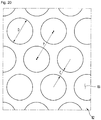
- the outer intake hole may include a plurality of holes, wherein a distance between adjacent holes is 1 mm or more and 1.5 mm or less.
- the outer intake hole may include a plurality of holes, wherein a distance between centers of adjacent holes is 7 mm or more and 10 mm or less.
- the outer intake hole may include a plurality of holes, wherein each of the holes is formed in a circular shape having a diameter of 7 mm or more and 8 mm or less.
- a refrigerator comprising: a cabinet including a back plate; an inner case disposed in front of the back plate, wherein the inner case has a storage chamber; a thermoelectric module, wherein thermoelectric module includes a thermoelectric element, a cooling sink mounted on a first face of the thermoelectric element and constructed for cooling the storage chamber, and a heat sink mounted on a second face of the thermoelectric element, wherein the first face is opposite to the second face; a heat-dissipation cover disposed spaced apart from the back plate in a rear direction, wherein the heat-dissipation cover has a plurality of outer intake holes defined therein; a fan disposed between the outer intake holes and the heat sink; a shroud disposed around the fan; and a blocking member constructed for blocking a gap between the shroud and the heat-dissipation cover.
- the blocking member is spaced apart from the heat sink.
- the blocking member may have a ring shape extending along a circumference of the shroud.
- a front end of the blocking member abuts a rear end of the shroud, wherein a rear end of the blocking member abuts a front end of the heat-dissipation cover.
- the blocking member may be disposed to surround at least a portion of an outer circumference of the shroud.
- a length of the blocking member in a rear-front direction is greater than a length of the blocking member in a radial direction.
- the length of the blocking member in the rear-front direction is 15 mm or more and 20 mm or less, while the length of the blocking member in the radial direction is 5 mm or more and 10 mm or less.
- a refrigerator comprising: a storage chamber constructed for storing food therein; a cooled-air flow channel positioned behind the storage chamber, wherein the channel is in communication with the storage chamber; a rear dissipated-heat flow channel positioned behind the cooled-air flow channel; a lower dissipated-heat flow channel communicating with the rear dissipated-heat flow channel, wherein the lower dissipated-heat flow channel is positioned below the storage chamber and is configured to eject air in a forward direction; a thermoelectric module including a cooling sink, a heat sink and a thermoelectric element, wherein the cooling sink is disposed in the cooled-air flow channel, wherein the heat sink is disposed within the rear dissipated-heat flow channel, wherein the thermoelectric element is disposed between the cooling sink and the heat sink; a heat dissipation cover disposed behind the rear dissipated-heat flow channel to cover the rear diss
- the blocking member has an annular shape extending along a circumference of the shroud, wherein the plurality of the outer intake holes communicate with an inner space in the blocking member in a rear-front direction.
- the vibration of the heat-dissipation fan transmitted to the heat sink can be minimized.
- the fixing pin since the fixing pin includes the head, and the fin coupling portion is included in the heat-dissipation fin of the heat sink, the fixing pin can be easily coupled to the fin coupling portion by fitting the head to the fin coupling portion.
- the blocking member blocks a gap between the heat-dissipation cover and the heat-dissipation fan to prevent flow disturbance caused by recirculation, and accordingly, the noise created by the flow disturbance can be reduced, and heat dissipation efficiency of the heat sink can be increased.
- the blocking member has the advantage of reducing the noise and vibration caused by the operation of the heat-dissipation fan.
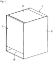
- Figure 1 is a perspective view showing the appearance of the refrigerator according to a first embodiment of the present disclosure.
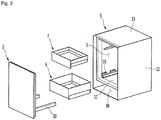
- Figure 2 is an exploded perspective view in which the refrigerator's main body, the door, and the storage compartment are separated from each other, according to the first embodiment of the present disclosure.
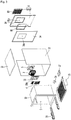
- Figure 3 is an exploded perspective view of the main body of the refrigerator according to the first embodiment of the present disclosure.
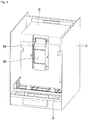
- Figure 4 is a perspective view of the back face of the inner case according to one embodiment of the present disclosure.
- the refrigerator according to the first embodiment of the present disclosure is a side table type refrigerator.
- the side table type refrigerator may also serve as a side table function in addition to food storage function.
- the side table type refrigerator may be placed next to the bedroom bed. Therefore, for the convenience of the user, the height of the side table type of the refrigerator is preferably similar to the height of the bed.
- the side table type refrigerator has a lower height than a general refrigerator and may be more compact.
- the refrigerator includes a main body 1 having the storage chamber S defined therein, a door 2 opening and closing the storage chamber S, and a thermoelectric module 3 to cool the storage chamber S.
- the main body 1 may be formed in a box shape.
- the height of the main body 1 is preferably 400 mm or more and 700 mm or less so that the present refrigerator may be utilized as a side table type refrigerator. That is, the height of the refrigerator may be 400mm or more and 700mm or less, but not limited thereto.
- the top face of the main body 1 may be horizontal.
- the user may use the top face of main body 1 as the top face of the side table.
- the main body 1 may be composed of a combination of a plurality of members.
- the main body 1 may include an inner case 10, a cabinet 12, 13, 14, a cabinet bottom 15, a drain pipe 16, and a tray 17.
- the main body 1 may further include a PCB cover 18 and a heat dissipation cover 8.
- the storage chamber S may be provided.
- the storage chamber S may define the inner space of the inner case 10.
- One side face of the inner case 10 may be open.
- the opened one side face may be opened and closed by the door 2.
- the front face of the inner case 10 may be opened.
- the thermoelectric module mount 10a may be formed on the rear face of the inner case 10.
- the thermoelectric module mount 10a may be formed by protruding a portion of the back face of the inner case 10 rearward.
- the thermoelectric module mount 10a may be formed closer to a top face of the inner case than the bottom face of the inner case 10.
- a cooled-air flow channel S1 (see Figure 16 ) may be provided in the inner space of the thermoelectric module mount 10a.
- the cooled-air flow channel S1 defines the inner space of the thermoelectric module mount 10a and may communicate with the storage chamber S.
- thermoelectric module mount 10a may have the thermoelectric module mounting hole 10b defined therein. At least a portion of a cooling sink 32, described below, of the thermoelectric module 3 may be disposed within the cooled-air flow channel S1.
- the cabinet 12, 13 and 14 may constitute an appearance of the refrigerator.
- the cabinet 12, 13, 14 may be disposed to surround the outer circumference of the inner case 10.
- the cabinet 12, 13, 14 may be spaced apart from the inner case 10. Foam may be inserted between the cabinet 12, 13, 14 and the inner case 10.
- the cabinet 12, 13, 14 may be formed of a combination of a plurality of members.
- the cabinet 12, 13, 14 may include an outer cabinet 12, a top cover 13, and a back plate 14.
- the outer cabinet 12 may be disposed outside of the inner case 10. More specifically, the outer cabinet 12 may be located to the left, right, and bottom of the inner case 10. However, the positional relationship between the outer cabinet 12 and the inner case 10 may be varied as needed.
- the outer cabinet 12 may be arranged to cover the left, right, and bottom faces of the inner case 10.
- the outer cabinet 12 may be spaced apart from the inner case 10.
- the outer cabinet 12 may define the left, right, and bottom faces of the refrigerator.
- the outer cabinet 12 may comprise a plurality of members.
- the outer cabinet 12 may include a base that forms the bottom face appearance of the refrigerator, a left cover that is placed on the left side of the base, and a right cover that is placed on the right side of the base.
- at least one of the base, left cover and right cover may be made of different material.
- the base may be formed of a synthetic resin material while the left plate and the right plate may be formed of metal such as steel or aluminum.
- the outer cabinet 12 is composed of one member.
- the outer cabinet 12 may be configured to have a lower plate, a left plate, and a right plate that are formed into a single piece as bent.
- the outer cabinet may be formed of a metal such as steel or aluminum.
- the top cover 13 may be disposed on top of the inner case 10.
- the top cover 13 may define the top face of the refrigerator.
- the user may use the top face of top cover 13 as the top face of the side table.
- the top cover 13 may be formed in a plate shape.
- the top cover 13 may be formed of a wood material.
- the appearance of the refrigerator may be made more aesthetic.
- the wood material is used in common side tables, so the user may feel the refrigerator more intuitively as a side table.
- the top cover 13 may be arranged to cover the top face of the inner case 10. At least a portion of the top cover 13 may be spaced apart from the inner case 10.
- the top face of the top cover 13 may be positioned precisely aligned with the top of the outer cabinet 12.
- the width of the horizontal direction of the top cover 13 may be the same as the inner width of the horizontal direction of the outer cabinet 12.
- the left and right sides of the top cover 13 may be disposed in contact with the inner surface of the outer cabinet 12.
- the back plate 14 may be arranged vertically.
- the back plate 14 may be disposed behind the inner case 10 and below the top cover 13.
- the back plate 14 may be disposed to face the rear of the inner case 10 in a rear-front direction.
- the back plate 14 may be disposed in contact with the inner case 10.
- the back plate 14 may be disposed close to the thermoelectric module mount 10a of the inner case 10.
- the back plate 14 may have a through-hole 14a defined therein.
- the hole 14a may be formed at a position corresponding to the thermoelectric module mounting hole 10b in the inner case 10.
- the size of the through-hole 14a may be greater than or equal to the size of the thermoelectric module mounting hole 10b in the inner case 10.
- the cabinet bottom 15 may be located below the inner case 10.
- the cabinet bottom 15 may support the inner case 10.
- the cabinet bottom 15 may be disposed between the outer bottom face of the inner case 10 and the inner bottom face of the outer cabinet 12.
- the cabinet bottom 15 may separate the inner case 10 from the inner bottom face of the outer cabinet 12.
- the cabinet bottom 15, along with the inner face of the outer cabinet 12, may define a lower dissipated-heat flow channel 92 (see Figure 16 ).
- the drain pipe 16 may communicate with the storage chamber S.
- the drain pipe 16 may be connected to a lower portion of the inner case 10.
- the pipe 16 may discharge water generated by defrosting or the like in the inner case 10.
- the tray 17 may be positioned below the drain pipe 16 and may receive water dropped from the drain pipe 16.
- the tray 17 may be disposed between the cabinet bottom 15 and the outer cabinet 12.
- the tray 17 may be located within the lower dissipated-heat flow channel 92 (see Figure 16 ).
- the water contained in the tray 17 may be evaporated by the hot air guided to the lower dissipated-heat flow channel 92. Due to this configuration, there is an advantage that the water in the tray 17 is not frequently emptied.
- the heat dissipation cover 8 may be disposed behind the back plate 14.
- the cover 8 may be disposed to face the back plate 14 in a rear-front direction.
- the heat-dissipation cover 8 may be spaced apart from the back plate 14.
- the heat-dissipation cover 8 may be arranged vertically.
- the top of the heat-dissipation cover 8 may be spaced apart from the top cover 13. That is, the height of the heat dissipation cover 8 may be lower than the height of the outer cabinet 12. In this case, the PCB cover 18, which will be described later, may be exposed in the rear direction of the main body 1.
- the present invention is not limited thereto. It is also possible that the top of the heat-dissipation cover 8 is disposed in contact with the top cover 13. In this case, the PCB cover 18 is positioned in front of the heat-dissipation cover 8 and may not be exposed in the backward direction of the main body 1.
- the heat dissipation cover 8 may include a cover body 81 and a suction grill 82 mounted on the cover body 81.
- the cover body 81 and the suction grill 82 may be integrally formed or formed of separate members.
- the heat dissipation cover 8 may have at least one outer intake hole 83 defined therein.
- a plurality of the outer intake holes 83 may be formed in the suction grill 82.
- the outer intake hole 83 may face the heat-dissipation fan assembly 5. When the heat-dissipation fan assembly 5 is driven, the outside air may be sucked into the heat-dissipation fan assembly 5 through the outer intake hole 83.
- the size and shape of the outer intake hole 83 may vary as needed.
- the suction grill 82 may serve as a finger guard to prevent the user's fingers from accessing the heat-dissipation fan assembly 5. It is preferable that the outer intake hole 83 has a size such that the user's finger is not inserted therein.
- the cover body 81 may have a cover through-hole 81a defined therein.
- the cover through-hole 81a may be formed at a position facing the heat-dissipation fan assembly 5.
- the cover through-hole 81a may be positioned between the suction grill 82 and the heat-dissipation fan assembly 5.
- the air sucked through the outer intake hole 83 may be sucked into the heat-dissipation fan assembly 5 through the cover through-hole 81a.
- the suction grill 82 may cover the cover through-hole 81.
- the suction grill 82 may face the heat-dissipation fan. More specifically, the front face of the suction grill 82 faces the heat-dissipation fan assembly 5 in the rear-front direction.
- the suction grill 82 may be spaced apart from the heat-dissipation fan assembly 5.
- the separation distance between the suction grill 82 and the heat-dissipation fan assembly 5 may be longer than the front maximum elastic deformation length of the suction grill 82. Thus, even when the user manually pushes the suction grill 82, the suction grill 82 may not touch the heat-dissipation fan assembly 5.
- the cover body 81 may have the depressed portion 84.
- the depressed portion 84 is depressed backward from the cover body 81.
- the depressed portion 84 may be formed by depressing a portion of the cover body 81 rearward.
- the cover through-hole 81a may be defined in the depressed portion 84.
- the suction grill 82 may be mounted on the depressed portion 84.
- the distance between the suction grill 82 and the heat-dissipating fan 5 may be increased as compared with the case where the cover body 81 does not have the depressed portion 84. This has the advantage of ensuring the required separation distance between the suction grill 82 and the heat-dissipation fan assembly 5, without increasing the length of the refrigerator's rear-front direction.
- the heat-dissipation cover 8, together with the back plate 14, may define a rear dissipated-heat flow channel 91 (see Figure 16 ).
- the rear dissipated-heat flow channel 91 may be located between the front face of the heat-dissipation cover 8 and the rear face of the back plate 14.
- the rear dissipated-heat flow channel 91 may be located between the front face of the cover body 81 and the rear face of the back plate 14.
- the air outside the refrigerator may be drawn into the heat-dissipation fan assembly 5 through the outer intake hole 83.
- the air sucked into the outer intake hole 83 may be heat-exchanged and heated in the heat sink 33.
- the heated air may then be directed to the rear dissipated-heat flow channel 91. This will be described in detail later.
- the refrigerator according to one embodiment of the present disclosure may further include a blocking member 85 blocking the gap 86 (see Figure 17 ) between the heat-dissipation fan assembly 5 and the heat-dissipation cover 8.
- the blocking member 85 may have a rectangular ring shape.
- the blocking member 85 may be formed by a combination of a plurality of members.
- the blocking member 85 may have a porous material.
- the material of the blocking member may be EPDM: Ethylene propylene.
- the blocking member 85 having a porous material is excellent in sound absorption and absorption performance, the blocking member 85 may effectively reduce vibration and noise generated by driving the heat-dissipation fan.
- the blocking member 85 may be disposed in contact with the heat-dissipation cover 8.
- the blocking member 85 may be arranged to contact the front face of the heat-dissipation cover 8. It is also possible that the blocking member 85 is disposed so as to be in contact with the inner circumference of the cover through-hole 81a.
- the blocking member 85 may be disposed in contact with the cover body 81 and/or the suction grill 82. When the blocking member 85 contacts the cover body 81, the blocking member 85 may contact the depressed portion 84.
- the blocking member 85 may block the gap 86 (see Figure 17 ) between the heat-dissipation fan assembly 5 and the heat-dissipation cover 8. This prevents the heated air from the heat sink 33 of the thermoelectric module 3 from flowing into the gap 86 between the heat-dissipation fan assembly 5 and the heat-dissipation cover 8 and being sucked into the heat-dissipation fan assembly 5.
- the door 2 may open or close the storage chamber S.
- the door 2 may be coupled to the main body 1, and the coupling schemes and the number of the doors are not particularly limited.
- the door 2 may be openable and closable via a hinge.
- the door may be a single one-way door or a plurality of bi-directional doors.
- the door 2 will be exemplarily described as a drawer-type door that slides in a rear-front direction while being connected to the main body 1.
- the door 2 may be joined to the front face of the main body 1.
- the door 2 may cover the open front face of the inner case 10, thereby opening and closing the storage chamber S.
- the door 2 may be formed of a wood material, but is not limited thereto.
- the vertical direction height of the door 2 may be less than the height of the outer cabinet 12.
- the bottom portion of the door 2 may be spaced apart from the inner bottom face of the outer cabinet 12.
- a dissipated-heat flow channel outlet 90 in communication with a lower dissipated-heat flow channel 92 may be defined.
- the door 2 may be coupled with the main body 1 in a sliding manner.
- the door 2 may have a pair of the slidable members 20.
- the slidable members 20 may be slidably mounted on a pair of the sliding rails 19 provided in the storage chamber S.
- the door 2 may be slid back and forth while maintaining a state of facing the open front face of the inner case 10.
- the sliding rails 19 may be respectively provided on the left inner side face and the inner right side face of the inner case 10.
- the sliding rail 19 may be provided at a position closer to the bottom face of the inner case than the top face of the inner case 10.
- the user may open the storage chamber S by pulling the door 1.
- the user may also close the storage chamber S by pushing in the door 2.
- the refrigerator may include at least one storage member 6 and 7 disposed in the storage chamber S.
- the types of the storage members 6 and 7 are not limited specifically.
- the storage members 6 and 7 may be shelf or drawers.
- the case that the storage members 6 and 7 are drawers will be referred to.
- Food may be placed or stored in the storage member 6 or 7.
- Each of the storage members 6 and 7 may be slidable in a rear-front direction.
- the left and right inner faces of the inner case 10 may be provided with at least a pair of the storage member rails corresponding to the storage members 6 and 7 respectively.
- Each of the storage members 6 and 7 may be slidably coupled to each of the storage member rails.
- the storage members 6 and 7 may be configured to move with the door 2.
- the storage members 6 and 7 may be detachably coupled to the door 2 via magnet. In this case, when the user pulls the door 2 and opens the storage chamber S, the storage members 6 and 7 may be moved forward along the door 2. The storage members 6 and 7 may move independently without moving with the door 2.
- the storage members 6 and 7 may be arranged horizontally in the storage chamber S.
- the top faces of the storage members 6 and 7 may be opened. Food may be stored in the inner spaces of the storage members 6 and 7.
- the storage members 6 and 7 may include the first storage member 6 and the second storage member 7.
- the first storage member 6 may be disposed below the second storage member 7.
- the rear-front direction lengths of the first storage member 6 and the second storage member 7 may be the same or different. Further, the vertical direction heights of the first storage member 6 and the second storage member 7 may be the same or different.
- thermoelectric module 3 may cool the storage chamber S.
- the thermoelectric module 3 may use the Peltier effect to keep the temperature of the storage chamber S low.
- thermoelectric module 3 may be arranged in a more front position than the heat-dissipation cover 8.
- the thermoelectric module 3 may include a thermoelectric element 31 (see Figure 6 ), a cooling sink 3 (see Figure 6 ), and a heat sink 33 (see Figure 6 ).
- the thermoelectric element 31 may include a low-temperature sub-element and a high-temperature sub-element.
- the low-temperature sub-element and the high-temperature sub-element may be determined according to the direction of a voltage applied to the thermoelectric element 31. Further, depending on the voltage applied to the thermoelectric element 31, the temperature difference between the low-temperature sub-element and the high-temperature sub-element may be determined.
- thermoelectric element 31 may be disposed between the cooling sink 32 and the heat sink 33 and may contact the cooling sink 32 and the heat sink 33, respectively.
- the low-temperature sub-element of the thermoelectric element 31 is in contact with the cooling sink 32.
- the high-temperature sub-element of the thermoelectric element 31 may contact the heat sink 33.
- thermoelectric module 3 The detailed configuration of the thermoelectric module 3 will be described in detail later.
- the refrigerator may further include a cooling fan assembly 4 to circulate air to the cooling sink 32 of the thermoelectric module 3 and the storage chamber S.
- the refrigerator may further include a heat-dissipation fan assembly 5 for flowing external air to the heat sink 33 of the thermoelectric module 3.
- the cooling fan assembly 4 may be disposed in front of the thermoelectric module 3.
- the heat-dissipation fan assembly 5 may be disposed behind the thermoelectric module 3.
- the cooling fan assembly 4 may be disposed facing the cooling sink 32 in the rear-front direction.
- the heat-dissipation fan assembly 5 may also be arranged to face the heat sink 33 in the rear-front direction.
- the cooling fan assembly 4 may be disposed in the inner space of the inner case 10.
- the cooling fan assembly 4 can flow the air in the storage chamber S to the cooled-air flow channel S1 (see Figure 16 ).
- the low temperature air which has heat-exchanged with the cooling sink 32 disposed in the cooled-air flow channel S1 may again flow into the storage chamber S to lower the temperature in the storage chamber S.
- the heat-dissipation fan assembly 5 may suck external air through the outer intake hole 83 defined in the heat-dissipation cover 8. More specifically, the heat-dissipation fan assembly 5 may draw in the outside air through the outer intake hole 83 defined in the suction grill 82.
- the air sucked by the heat-dissipation fan assembly 5 may heat-exchange with the heat sink 33 located between the back plate 14 and the heat-dissipation cover 8.
- the heat exchanged air may then heat-dissipate the heat sink 33.
- the hot air which has heat-exchanged with the heat sink 33 is guided to the rear dissipated-heat flow channel 91 (see FIG. 16 ) and the lower dissipated-heat flow channel 92 (see FIG. 16 ) in this order and may be released into the dissipated-heat flow channel outlet 90 located below the door 2.
- the heat-dissipation fan assembly 5 may be arranged to face the suction grill 82.
- the heat-dissipation fan assembly 5 may be arranged to face the outer intake hole 83.
- cooling fan assembly 4 The detailed configuration of the cooling fan assembly 4 and heat-dissipation fan assembly 5 will be described in detail later.
- Figure 5 is a perspective view of the thermoelectric module and heat-dissipation fan according to the first embodiment of the present disclosure.
- Figure 6 is an exploded perspective view of the thermoelectric module and heat-dissipation fan shown in Figure 5 .
- Figure 7 is an exploded perspective view of the thermoelectric module and the heat-dissipation fan shown in Figure 5 , viewed in a different direction.
- Figure 8 is a cross-sectional view of the thermoelectric module and heat-dissipation fan according to the first embodiment of the present disclosure.
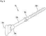
- Figure 9 is a perspective view of the fixing pin according to the first embodiment of the present disclosure.
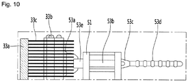
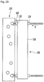
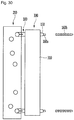
- Figure 10 is a side view to illustrate the configuration in which the thermoelectric module and the heat-dissipation fan are fixed by the fixing pin.
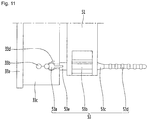
- Figure 11 is a top plan view to illustrate the configuration in which the thermoelectric module and the heat-dissipation fan are fixed by the fixing pin.
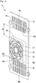
- Figure 12 is a front view of the thermoelectric module according to the first embodiment of the present disclosure.
- Figure 13 is a diagram illustrating a configuration in which the thermoelectric module is mounted in the thermoelectric module holder, according to the first embodiment of the present disclosure.
- Figure 14 is an exploded perspective view wherein the thermoelectric module is mounted on the inner case and the thermoelectric module holder, according to the first embodiment of the present disclosure.
- thermoelectric module 3 the thermoelectric module 3
- heat-dissipation fan assembly 5 the detailed configuration of the thermoelectric module 3, and the heat-dissipation fan assembly 5 will be described with reference to FIGS. 5 to 14 .
- the thermoelectric module 3 may utilize the Peltier effect to keep the temperature of the storage chamber S low.
- the thermoelectric module 3 includes the thermoelectric element 31, the cooling sink 32, and the heat sink 33.
- the thermoelectric element 31 may have the fuse 35. When an overvoltage is applied to the thermoelectric element, the fuse 35 may cut off the voltage applied to the thermoelectric element 31.
- the cooling sink 32 may be implemented as a cooling heat-exchanger connected to the low-temperature sub-element of the thermoelectric element 31.
- the cooling sink 32 may cool the storage chamber S.
- the heat sink 33 may be implemented as a heating heat-exchanger connected to the high-temperature sub-element of the thermoelectric element 31.
- the heat sink 33 may heat-dissipate the heat absorbed by the cooling sink 32.
- the thermoelectric module 3 may be positioned further forward than the heat-dissipation cover 8.
- the cooling sink 32 is disposed closer to the inner case 10 than the heat sink 33.
- the cooling sink 32 may be disposed in front of the thermoelectric element 31.
- the cooling sink 32 may be kept at a low temperature in contact with the low-temperature sub-element of the thermoelectric element 31.
- the heat sink 33 is disposed closer to the heat-dissipation cover 8 that the cooling sink 32.
- the heat sink 33 may be maintained at a high temperature in contact with the high-temperature sub-element of the thermoelectric element 31.
- the heat sink 33 may be disposed below the controller 18a to be described later.
- thermoelectric module 3 is configured so that any one of the thermoelectric element 31, the cooling sink 32, and the heat sink 33 is passed through the hole 14a defined therein.
- the heat sink 33 may pass through the through-hole 14a.
- the thermoelectric element 31 and the cooling sink 32 may be positioned in front of the through-hole 14a, while the heat sink 33 may be partially located behind the through-hole 14a.
- the cooling sink 32 may include a cooling plate 32a and a cooling fin 32b.
- the cooling plate 32a may be disposed in contact with the thermoelectric element 31. A portion of the cooling plate 32a may be inserted into a thermoelectric element accommodation hole defined in a thermal insulation member 37 and may be in contact with the thermoelectric element 31. The cooling plate 32a may be positioned between the cooling fin 32b and the thermoelectric element 31. The cooling plate 32a may contact the low-temperature sub-element of the thermoelectric element 31 to transfer the heat of the cooling fin 32b to the low-temperature sub-element of the thermoelectric element 31.
- the cooling plate 32a may be formed of a material having a high thermal conductivity.
- the cooling plate 32a may be located in the thermoelectric module mounting hole 10b of the inner case 10.
- the cooling sink 32 may be disposed so as to block the thermoelectric module mounting hole 10b of the inner case 10.
- the cooling plate 32a may block the thermoelectric module mounting hole 10b of the inner case 10.
- the cooling fin 32b may be disposed in contact with the cooling plate 32a.
- the cooling fin 32b may protrude from the cooling plate 32a.
- the cooling fin 32b may be located in front of the cooling plate 32a. An at least portion of the cooling fin 32b may be located within the cooled-air flow channel S1 defined in the thermoelectric module mount 10a. Thus, the at least a portion of the cooling fin 32b may be heat-exchanged with air in the cooled-air flow channel S1 to cool the air therein.
- the cooling fin 32b may have a plurality of fins to increase the heat exchange area with air.
- the cooling fin 32b may be formed to guide the air in the vertical direction.
- Each of the plurality of fins constituting the cooling fin 32b may be embodied as a vertical plate having a left side and a right side and extending in a vertical direction.
- the cooling fin 32b may be disposed between the fan 42 of the cooling fan assembly 4 and the thermoelectric element 31.
- the cooling fin 32b may guide the air blown from the fan 42 of the cooling fan assembly 4 to the upper ejection hole 45 and the lower ejection hole 46.
- the air blown from the fan 42 of the cooling fan assembly 4 may be dispersed up and down by the cooling fin 32b.
- the heat sink 33 may include a heat-dissipation plate 33d, a heat-dissipation pipe 33b, and a heat-dissipation fin 33c.
- the heat sink 33 may further includes an element contacting plate 33a.
- the element contacting plate 33a may be disposed in contact with the thermoelectric element 31. A portion of the element contacting plate 33a may be inserted into a thermoelectric element receiving hole 37a formed in the thermal insulating member 37 to contact the thermoelectric element 31.
- the heat-dissipation plate 33d may contact the heat-dissipation fin 33c and the heat-dissipation pipe 33b may be located between the heat-dissipation plate 33d and the element contacting plate 33a.
- the element contacting plate 33a may contact the high-temperature sub-element of the thermoelectric element 31 to conduct heat to the heat-dissipation pipe 33b, the heat-dissipation pipe 33b may conduct heat to the heat-dissipation fin 33c and the heat-dissipation plate 33d.
- the heat dissipation plate 33d and the element contacting plate 33a may be formed of a material having a high thermal conductivity.
- At least one of the heat-dissipation plate 33d and the heat-dissipation fin 33c may be disposed in the through-hole 14a of the back plate 14.
- the heat-dissipation pipe 33b may be implemented as a heat pipe accommodating a thermoelectric fluid therein. A portion of the heat-dissipation pipe 33b may be disposed to pass through the heat-dissipation fin 33c.
- thermoelectric fluid contained in the heat-dissipation pipe 33b may be evaporated, while in a portion of the heat-dissipation pipe 33b contacting the heat-dissipation fin 33c, the thermoelectric fluid contained therein may be condensed.
- the thermoelectric fluid circulates in the heat-dissipation pipe 33b via density difference and/or gravity, such that the heat of the heat-dissipation plate 33d may be conducted to the element contacting plate 33a and the heat-dissipation fin 33c.
- the heat-dissipation fin 33c may contact at least one of the heat-dissipation plate 33d and the heat-dissipation pipe 33b.
- the heat-dissipation fin 33c may be spaced apart from the heat-dissipation plate 33d and may be connected to the heat-dissipation plate 33d through the heat-dissipation pipe 33b.
- the heat-dissipation pipe 33b may be omitted.
- the heat-dissipation fin 33c may include a plurality of fins vertically disposed on the heat-dissipation pipe 33b.
- the heat-dissipation fin 33c may guide the air blown from the heat-dissipation fan assembly 5.
- the air guiding direction by the heat-dissipating fin 33c may be different from the air guiding direction by the cooling fin 32b.
- the heat-dissipation fin 33c may guide the air in a horizontal direction.
- the heat-dissipating fin 33c may be configured to guide the air in the horizontal direction, particularly, in the left-right direction among the rear-front direction and the left-right direction.
- Each of the plurality of fins constituting the heat-dissipation fin 33c includes a horizontal plate having a top face and a bottom face and extending in the horizontal direction.
- the plurality of fins are stacked in a vertical direction.
- the heat-dissipation plate 33d may be located between the heat-dissipation fin 33c and the thermoelectric element 31.
- the heat-dissipation fin 33c may be located behind the heat-dissipation plate 33d.
- the heat-dissipation fin 33c may be located behind the back plate 14.
- the heat-dissipation fin 33c may be positioned between the back plate 14 and the heat-dissipation cover 8.
- the heat-dissipation fin 33c may be heat-dissipated by heat exchange with the external air sucked by the heat dissipation fan 5.
- thermoelectric module 3 may further include a module frame 34 and the thermal insulation member 37.
- the module frame 34 may be box-shaped.
- the module frame 34 may have a space therein to accommodate the thermal insulating member 37 and the thermoelectric element 31.
- the module frame 34 and the thermal insulating member 37 may protect the thermoelectric element 31.
- the module frame 34 may be formed of a material that minimizes heat loss due to heat conduction.
- the module frame 34 may be made of a non-metallic material such as plastic.
- the module frame 34 may prevent heat from the heat sink 33 from being conducted to the cooling sink 32.
- a gasket 36 may be provided on the front face of the module frame 34.
- the gasket 36 may be made of an elastic material such as rubber.
- the gasket 36 may be formed in a rectangular ring shape, but the present disclosure is not limited thereto.
- the gasket 36 may be a sealing member.
- the gasket 36 may be disposed on the rear face of the thermoelectric module mount 10a and/or on the circumference of the thermoelectric module mounting hole 10b.
- the gasket 36 may be disposed between the module frame 34 and the thermoelectric module mount 10a and may be compressed in the rear-front direction.
- the gasket 36 may prevent cold air in the cooled-air flow channel S1 defined in the thermoelectric module mount 10a from leaking into the gap between the thermoelectric module mounting hole 11b and the cooling sink 32.
- the module frame 34 may include a coupling portion 34a.
- the coupling portion 34a may extend outwardly from an at least portion of the periphery of the module frame 34.
- the coupling portion 34a may extend outwardly from the left and right sides of the module frame 34, respectively.
- the coupling portion 34a may include a boss 34b.
- a thread may be formed in the boss 34b.
- a fastener such as a bolt may be fastened to the thread.
- the fastener may be coupled to boss 34b of the coupling portion 34a of the module frame 34 through a fastener hole 10c formed in the inner case 10 inside the inner case 10.
- thermoelectric module 3 and the inner case 10 may be firmly fastened such that it is possible to prevent the cold air in the inner case 10 from leaking to the outside.
- the thermal insulating member 37 may be arranged to surround the outer circumference of the thermoelectric element 31.
- the thermal insulating member 37 may be disposed to enclose the top face, left face, bottom face, and right face of the thermoelectric element 31.
- the thermoelectric element 31 may be located within the thermal insulating member 37.
- the thermal insulating member 37 may be provided with a element receiving hole 37a defined therein and opened in the rear-front direction.
- the thermoelectric element 31 may be located within the element receiving hole 37a.
- the thickness of the rear-front direction of the thermal insulation member 37 may be larger than the thickness of the thermoelectric element 31.
- the thermal insulating member 37 may prevent heat from being conducted to an outer periphery of the thermoelectric element 31, thereby increasing the efficiency of the thermoelectric element 31. That is, the circumference of the thermoelectric element 31 may be surrounded by the thermal insulating member 37, such that heat generated from the heat sink 33 may transfer to the cooling sink 32 at a minimum level.
- the thermal insulating member 37 and the thermoelectric element 31 may be disposed in the inner space of the module frame 34 and may be protected by the module frame 34.
- the module frame 34 may be arranged to surround the outer perimeter of the thermal insulating member 37.
- the refrigerator may further comprise a thermoelectric module holder 11 (see FIG. 3 ) for fixing the thermoelectric module 3 to the inner case 10 and/or back plate 14.
- thermoelectric module holder 11 may couple the thermoelectric module 3 to the inner case 10 and/or back plate 14.
- thermoelectric module holder 11 may be coupled to the thermoelectric module mount 10a and/or back plate 14 of the inner case 10 via a fastener (not shown) such as a screw.
- thermoelectric module holder 11 together with the thermoelectric module 3, may block the through-hole 14a of the back plate 14.
- the thermoelectric module holder 11 may be provided with a hollowed portion 11a.
- the hollowed portion 11a may be formed by protruding a portion of the thermoelectric module holder 11 forward.
- the module frame 34 may be inserted and fitted into the hollowed portion 11a.
- the hollowed portion 11a may wrap around the module frame 34.
- the front portion of the thermoelectric module 3 may be located in front of the through-hole 14a of the back plate 14, while the rear portion of the thermoelectric module 3 may be located behind the through-hole 14a of the back plate 14.
- the thermoelectric module 3 may further include a sensor 39.
- the sensor 39 may be disposed on the cooling sink 32.
- the sensor 39 may be a temperature sensor or a defrost sensor.
- the heat-dissipation fan assembly 5 may be disposed behind the thermoelectric module 3.
- the heat-dissipation fan assembly 5 may be arranged to face the heat sink 33 in the rear of the heat sink 33.
- the heat-dissipation fan assembly 5 may blow external air into the heat sink 33.
- the heat-dissipation fan assembly 5 may include a fan 52 and a shroud 51 disposed around the fan 52.
- the fan 52 of the heat-dissipation fan assembly 5 may be an axial fan.
- the heat-dissipation fan assembly 5 may be disposed apart from the heat sink 33. Thus, the flow resistance of the air blown by the heat-dissipation fan assembly 5 may be minimized, and the heat exchange efficiency in the heat sink 33 may be increased.
- the heat-dissipation fan assembly 5 may be provided with at least one fixing pin 53.
- the fixing pin 53 is in contact with the heat sink 33.
- the fixing pin 53 may separate the heat-dissipation fan assembly 5 from the heat sink 33 and, at the same time, fix the heat-dissipation fan assembly 5 to the heat sink 33.
- the fixing pin 53 may be formed of a material having a low thermal conductivity such as rubber or silicone.
- the fixing pin 53 may be formed of a material capable of absorbing vibration. The appearance of the fixing pin 53 may be deformed such that the fixing pin 53 absorbs the vibration.
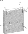
- the fixing pin 53 may include a head 53a, a first fixing portion 53e, a body 53b and a second fixing 53c.
- the head 53a may be in contact with the heat sink 33.
- the head 53a may contact the heat-dissipation pipe 33b and/or the heat-dissipation fin 33c of the heat sink 33.
- a groove 33d may be formed in a portion adjacent to a portion which the heat pipe 33b penetrates.
- the groove 33d formed in the heat-dissipation fin 33c may be elongated in a vertical direction.
- the head 53a may be settled in a fin having no groove and disposed just below a fin having the groove 33d formed therein.
- the head 53a of the fixing pin 53 may be inserted and fixed to the groove 33d of the heat-dissipation fin 33c.
- a width of an entrance part in the groove 33d may be narrower than other parts.
- the head 53a may be fitted to the groove 33d in the vertical direction. Hence, the head 53a may be prevented from being detached from the groove 33d in a horizontal direction in a state of fitting a head to the groove 33d.
- the first fixing portion 53e may be formed in one side of the head 53a.
- the body 53b may extend from the first fixing portion 53e in the horizontal direction.
- a length of the body 53b may be longer than a length of the first fixing portion 53e, and a diameter of the body 53b may be smaller than a diameter of the first fixing portion 53e.
- the second fixing portion 53c may be disposed on an opposite side of the first fixing portion 53e in the body 53b.
- the length of the body 53b may be longer than a length of the second fixing portion 53c, and the diameter of the body 53b may be smaller than a diameter of the second fixing portion 53c.
- the body 53b may be coupled to the heat-dissipation fan 5. More specifically, the body 53b may be coupled to a fixing pin through-hole 51a formed in the shroud 51.
- the diameter of the body 53b may be the same as or smaller than the fixing pin through-hole 51a.
- the diameters of the first fixing portion 53e and the second fixing portion 53c may be larger than the diameter of the fixing pin through-hole 51a.
- the fixing pin 53 is formed of a deformable material, and thus, the second fixing portion 53c may penetrate the fixing pin through-hole 51a.
- the diameter of the second fixing portion 53c may be smaller, in order that the second fixing portion 53c can easily penetrate the fixing pin through-hole 51a.
- the second fixing portion 53c may be formed in a shape of a truncated cone or a circular cone.
- a length of the body 53b in a rear-front direction may be the same as a thickness of the heat-dissipation fan 5 in a rear-front direction.
- the first fixing portion 53e is in contact with a front surface of the heat-dissipation fan 5 and the second fixing portion 53c is in contact with a rear surface of the heat-dissipation fan 5.
- the heat-dissipation fan 5 is spaced apart from the heat sink 33 by a length of the first fixing portion 53e.
- the fixing portion 53 may further comprise a fixing guide 53d.
- the fixing guide 53d may extend from the second fixing portion 53c.
- a diameter of the fixing guide 53d may be smaller than the second fixing portion 53c.
- a part of the fixing guide 53d may be removed in a state that the heat-dissipation fan 5 is fixed to the fixing pin 53.
- Figure 15 is a perspective view of a cooling fan assembly according to the first embodiment of the present disclosure.
- the cooling fan assembly 4 may be disposed in front of the thermoelectric module 3 and may be disposed to face the cooling sink 32.
- the cooling fan assembly 4 may circulate the air to the cooled-air flow channel S1 and the storage chamber S. Forced convection may be generated between the cooled-air flow channel S1 and the storage chamber S by the cooling fan assembly 4.
- the cooling fan assembly 4 may flow the air in the storage chamber S to the cooled-air flow channel S1. Then, the hot air which has heat-exchanged with the cooling sink 32 disposed in the cooled-air flow channel S1 may then flow back to the storage chamber S to keep the temperature in the storage chamber S low.
- the cooling fan assembly 4 may include a fan cover 41 and a fan 42.
- the fan cover 41 may be disposed in the inner space of the inner case 10.
- the fan cover 41 may be arranged vertically.
- the fan cover 41 may partition the storage chamber S and the cooled-air flow channel S1.
- the storage chamber S may be located in front of the fan cover 41.
- the cooled-air flow channel S1 may be located at the rear of the fan cover 41.
- the fan cover 41 may have an inner intake hole 44 and inner ejection holes 45 and 46 defined therein.
- the number, size and shape of the inner intake hole 44 and inner ejection holes 45 and 46 may vary as needed.
- the inner ejection holes 45 and 46 may include the upper ejection hole 45 and the lower ejection hole 46.
- the upper ejection hole 45 may be formed above the inner intake hole 44, while the lower ejection hole 46 may be formed below the inner intake hole 44. With this configuration, the temperature distribution of the storage chamber S may be uniform.
- the area of the upper ejection hole 45 and the area of the lower ejection hole 46 may be the same.
- the distance G1 between the top 46a of the lower ejection hole 46 and the bottom 44b of the inner intake hole 44 may be smaller than the distance G2 between the bottom 45b of the upper ejection hole 45 and the top 44a of the inner intake hole 44. That is, the inner intake hole 44 may be formed closer to the lower ejection hole 46 than to the upper ejection hole 45.
- the area of the inner intake hole 44 may vary depending on the size of the fan 41.
- the area of the inner ejection hole 45 and 46 may be configured to be at a predetermined ratio with respect to the area of the inner intake hole 44.
- the area of the inner ejection holes 45 and 46 may be larger than the area of the inner intake hole 44.
- the area of the inner ejection holes 45 and 46 may be 1.3 times or more and 1.5 times or less of the area of the inner intake hole 44.
- the fan cover 41 may be provided with a fan accommodation portion 47.
- the fan accommodation portion 47 may be formed by projecting the front face portion of the fan cover 41 forward.
- a fan accommodation space may be formed in the fan accommodation portion 47.
- At least a portion of the fan 42 may be disposed within a fan accommodation space defined within the fan accommodation portion 47.
- the inner intake hole 44 may be defined in the fan accommodation portion 47.
- the fan 42 may be disposed within the cooled-air flow channel S1 and disposed behind the fan cover 41.
- the fan cover 41 may cover the fan in front of the fan 42.
- the fan 42 may be arranged to face the cooling sink 32.
- the fan 42 may be disposed between the inner intake hole 44 and the cooling sink 32.
- the fan 42 may be arranged to face the inner intake hole 44.
- the air in the storage chamber S is sucked into the cooled-air flow channel S1 through the inner intake hole 44, and is heat-exchanged with the cooling sink 32 of the thermoelectric module 3, thereby cooling the air.
- the cooled air may be ejected through the inner ejection holes 45 and 46 into the storage chamber S. Thereby, the temperature of the storage chamber S may be kept low.
- a portion of the air cooled from the cooling sink 32 may be directed upward and ejected through the upper ejection hole 45 to the storage chamber S, while another portion of the air-cooled may be directed downward and ejected into the storage chamber S through a lower ejection hole 46.
- Figure 16 is a cross section of the refrigerator according to the first embodiment of the present disclosure.
- Figure 17 is an enlarged cross-sectional view of an outer portion of the thermoelectric module of the refrigerator shown in Figure 16 .
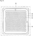
- Figure 18 is a front view of a heat-dissipation cover according to the first embodiment of the present disclosure.
- each of the inner intake hole 44 and the lower ejection hole 46 may be directed toward between the first storage member 6 and the second storage member 7. Further, the at least portion of the upper ejection hole 45 may be directed toward between the top face of the storage chamber 10 and the second storage member 7.
- the lower portion 46b of the lower ejection hole 46 may be located at the rear and upper position of the first storage member 6. More specifically, the lower portion 46b of the lower ejection hole 46 may be located at the rear and upper position of the rear top portion 63 of the first storage member 6.
- the rear face 61 of the first storage member 6 may be disposed to face the lower portion of the lower ejection hole 46 in the horizontal direction.
- the lower ejection hole 46 may not overlap the first storage member 6 in the horizontal direction. That is, the first storage member 6 may be disposed so as not to screen the lower ejection hole 46 in the horizontal direction.
- the flow of the low-temperature air ejected to the lower ejection hole 46 may not be disturbed by the first storage member 6, so that air circulation in the storage chamber S may be smooth. Further, the cold air may be lowered to keep the food stored in the first storage member 6 at a low temperature.
- the lower ejection hole 46 and the first storage member 6 may be spaced apart from each other to further facilitate air circulation within the storage chamber S.
- the lower portion 46b of the lower ejection hole 46 and the first storage member 6 are spaced apart from each other by the first horizontal spacing D1 in the horizontal direction, while the lower portion 46b of the lower ejection hole 46 and the first storage member 6 may be spaced apart from each other by the first vertical spacing H1 in the vertical direction.
- the first horizontal spacing D1 may refer to a horizontal distance between an extension extending vertically upwards from the rear face 61 of the first storage member 6 and the lower ejection hole 46.
- the first vertical spacing H1 may mean the vertical distance between an extension extending horizontally forward from the lower portion 46b of the lower ejection hole 46 and a top 60 of the first storage member 6.
- the first horizontal spacing D1 may refer to the spacing between the rear face of the storage chamber S and the first storage member.
- the rear face of the storage chamber S may be the front face of the fan cover 41.
- the first vertical spacing H1 may refer to the height difference between the lower portion 46b of the lower ejection hole 46 and the top 60 of the first storage member 6.
- the portion of the upper ejection hole 45 may overlap the second storage member 7 in the horizontal direction. More specifically, the upper portion of the upper ejection hole 45 may be directed toward between the top 70 of the second storage member 7 and the top face of the storage chamber S, while the lower portion of the upper ejection hole 45 may face the rear face 71 of the second storage member 7.
- the upper portion 45a of the upper ejection hole 45 may be located at the rear upper position of the rear top 73 of the second storage member 7.
- the inner intake hole 44 of the fan cover 41 may be formed closer to the lower ejection hole 46 of the cover 41 than to the upper ejection hole 45 of the cover 41.
- the height of the storage chamber S may be further lowered to satisfy the positional relationship between the storage member 6 and 7 and the inner intake hole 44 and the inner ejection hole 45 and 46 as described above.
- At least a portion of the rear face 71 of the second storage member 7 may be formed to be inclined upward.
- a portion of the rear face 71 of the second storage member 7 facing the upper ejection hole 45 may be an inclined face 72 inclined upward.
- the lower portion of the upper ejection hole 45 may face the inclined face 72.
- the inclined face 72 may guide the low temperature air ejected from the upper ejection hole 45 to the top of the second storage member 7. As a result, the food stored in the second storage member 7 may be kept at a low temperature.
- the upper ejection hole 45 and the second storage member 7 may be spaced apart from each other to further facilitate air circulation within the storage chamber S.
- the upper portion 45a of the upper ejection hole 45 and the second storage member 7 are spaced apart from each other by the second horizontal spacing D2 in the horizontal direction, and, at the same time, the upper portion 45a of the upper ejection hole 45 and the second storage member 7 may be spaced apart from each other by the second vertical spacing H2 in the vertical direction.
- the second horizontal spacing D2 may mean the horizontal distance between the rear face 71 of the second storage member 7 and the upper ejection hole 45.
- the second vertical spacing H2 may mean a vertical distance between an extension extending horizontally forward from the upper portion 45a of the upper ejection hole 45 and a top 70 of the second storage member 7.
- the second horizontal spacing D2 may mean spacing between the rear face of the storage chamber S and the second storage member 7.
- the rear face of the storage chamber S may be the front face of the fan cover 41.
- the second vertical spacing H2 may refer to the height difference between the upper portion 45a of the upper ejection hole 45 and top 60 of the second storage member 7.
- the second horizontal spacing D2 between the rear face 71 of the second storage member 7 and the upper ejection hole 45 is greater than the first horizontal spacing D1 between the rear face 61 of the first storage member 6 and the lower ejection hole 46.
- the second storage member 7 faces the portion of the upper ejection hole 45 in the horizontal direction, requiring additional spacing for air circulation within the storage chamber S.
- the rear-front direction length of the first storage member 6 may be longer than the rear-front direction length of the second storage member 7.
- the inner intake hole 44 may be directed toward between the first storage member 6 and the second storage member 7.
- the inner intake hole 44 may not overlap the second storage member 7 in the horizontal direction. Thereby, air flow to the inner intake hole 44 may be smooth and the temperature of the storage chamber S may be lowered to improve the refrigerating performance of the refrigerator.
- the vertical direction height of the second storage member 7 may be smaller than the vertical direction height F1 of the first storage member 6. Due to such a configuration, a food container having a larger height such as a bottle or the like may be housed in the first storage member 6, while the second storage member 7 may contain a food container with a relatively smaller height.
- the refrigerator may have the dissipated-heat flow channel 91 and 92 and the cooled-air flow channel S1 defined therein.
- the cooling sink 32 may be disposed in the cooled-air flow channel S1, while the heat sink 33 may be disposed within the dissipated-heat flow channels 91 and 92.
- the cooled-air flow channel S1 may communicate with the storage chamber S, while the dissipated-heat flow channels 91 and 92 may communicate with the outside of the main body 1.
- the air in the storage chamber S may be guided into the cooled-air flow channel S1 by driving the cooling fan assembly 4 and then may be heat-exchanged with the cooling sink 32 and then may be cooled.
- the cooled-air flow channel S1 may be located in the inner space of the inner case 10. In more detail, the cooled-air flow channel S1 may be located in the inner space of the thermoelectric module mount 10a.
- the cooled-air flow channel S1 may be defined by a rear face of the fan cover 41 and an inner face of the thermoelectric module mount 10a.
- the cooled-air flow channel S1 may communicate with the inner intake hole 44 and the inner ejection holes 45 and 46.
- the cooling sink 32 may be arranged to face the fan 42.
- the cooled-air flow channel S1 may guide air sucked into the inner intake hole 44 to the inner ejection holes 45 and 46.
- the outside air may be guided to the dissipated-heat flow channels 91 and 92 by driving the heat-dissipation fan 5, and then may be heat-exchanged with the heat sink 33 and may be heated.
- the dissipated-heat flow channels 91 and 92 may be located outside the inner case 10.
- the dissipated-heat flow channels 91 and 92 may include the rear dissipated-heat flow channel 91 located at the rear of the inner case 10 and the lower dissipated-heat flow channel 92 located to the lower side of the inner case 10.
- the rear dissipated-heat flow channel 91 may be located between the back plate 14 and the heat-dissipation cover 8.
- the rear dissipated-heat flow channel 91 may be defined by the rear face of the back plate 14 and the inner face of the heat-dissipation cover 8.
- the heat sink 33 may be disposed in the rear dissipated-heat flow channel 91.
- the heat sink 33 may be arranged to face the heat-dissipation fan assembly 5.
- the at least portion of the rear dissipated-heat flow channel 91 may act as a machine room.
- the rear dissipated-heat flow channel 91 may communicate with the outer intake hole 83.
- the rear dissipated-heat flow channel 91 may direct the air drawn into the outer intake hole 83 by the heat-dissipation fan assembly 5 to the lower dissipated-heat flow channel 92.
- the lower dissipated-heat flow channel 92 may be located between the cabinet bottom 15 and the outer cabinet 12.
- the lower dissipated-heat flow channel 92 may communicate with the rear dissipated-heat flow channel 91.
- the lower dissipated-heat flow channel 92 may direct air flowing from the rear dissipated-heat flow channel 91 to the dissipated-heat flow channel outlet 90 below the door 2.
- the PCB cover 18 may cover the controller 18a.
- the controller 18a may include electronic components such as a PCB substrate.
- the controller 18a may receive and store the measured values form each sensor provided in the refrigerator.
- the controller 18a may also control the thermoelectric module 3, the cooling fan assembly 4, and the heat-dissipation fan assembly 5.
- the controller 18a may further control additional components as needed.
- the controller 18a may be located above the heat sink 33 and/or heat-dissipation fan assembly 5.
- a barrier 18b may be provided between the heat sink 33 and/or the heat-dissipation fan assembly 5 and the controller 18a. That is, the barrier 18b may be located below the controller 18a.
- the barrier 18b may prevent the controller 18a from overheating by heat emitted to the heat sink 33. Further, the barrier 18b may prevent heated air from the heat sink 33 from flowing to the controller 18a.
- the barrier 18b may be mounted on the heat-dissipation cover 8 and/or back plate 14. Alternatively, the barrier 18b may be mounted on the PCB cover 18 or integrally formed with the PCB cover 18.
- the PCB cover 18 may be disposed above or in front of the heat dissipation cover 8.
- the PCB cover 18 may cover the rear and/or top portion of the controller 18a.
- the PCB cover 18 may be disposed below the top cover 13 and may be disposed behind the inner case 10. Further, the PCB cover 18 may be located above the heat sink 33 and/or heat-dissipation fan assembly 5 of the thermoelectric module 3 as described below.
- the PCB cover 18 may cover the rear of the controller 18a.
- the controller 18a it is possible to prevent the controller 18a from being exposed to the rear of the main body 1.
- the PCB cover 18 may cover the top side of the controller 18a, and may not cover the rear side of the controller 18a.
- the blocking member 85 may block the gap 86 between the heat-dissipation fan assembly 5 and the heat-dissipation cover 8. More specifically, the blocking member 85 may block the gap 86 between the shroud 51 of the heat-dissipation fan assembly 5 and the heat-dissipation cover 8.
- the air sucked into the heat-dissipation fan assembly 5 through the outer intake hole 83 may be blown to the heat sink 33 and heated by the heat sink 33. Thereby, a portion of the air heated by the heat sink 33 flows into the gap 86 between the shroud 51 and the heat-dissipation cover 8 and is re-sucked into the heat-dissipation fan assembly 5, resulting in flow disturbance.
- This flow disturbance may produce noise of a tone having a low frequency range. Further, the already heated air may be blown back to the heat sink 33 and, thus, the heat dissipation efficiency of the heat sink 33 may be lowered.
- the blocking member 85 prevents the air heated by the heat sink 33 from flowing into the gap 86 between the heat-dissipation fan assembly 5 and the heat-dissipation cover 8 so that the air is prevented from being sucked into the heat-dissipating fan assembly 5. That is, the re-circulation phenomenon of the heated air may be prevented. Thereby, the noise generated by the flow disturbance may be reduced, and the heat-dissipation efficiency of the heat sink 33 may be increased.
- the blocking member 85 may be made of a porous material. As a result, the blocking member 85 may effectively reduce the vibration and noise generated in the driving of the heat-dissipation fan assembly 5 itself.
- the blocking member 85 may be disposed to contact each of the heat-dissipation fan assembly 5 and the heat-dissipation cover 8.
- the blocking member 85 may be arranged so as to surround the outer periphery of the heat-dissipation fan assembly 5. More specifically, the blocking member 85 may be arranged to surround the outer circumference of the shroud 51. The blocking member 85 may also touch the shroud 51.
- the blocking member 85 may be disposed in contact with the heat-dissipation cover 8 and may be arranged to contact the front face of the cover 8.
- the blocking member 85 may be disposed in contact with the cover body 81 and/or the suction grill 82. When the blocking member 85 contacts the cover body 81, the blocking member 85 may contact the depressed portion 84.
- the rear-front direction length L of the blocking member 85 may be longer than its thickness T.
- the length L of the blocking member 85 in the rear-front direction may be 15 mm or more and 20 mm or less, while the thickness T of the blocking member 85 may be 5 mm or more and 10 mm or less.
- Figure 19 shows the rear view of the refrigerator according to the first embodiment of the present disclosure.
- Figure 20 shows an enlarged view of the portion of the suction grill shown in Figure 19 .
- the outer intake hole 83 defined in the heat-dissipation cover 8 may have a plurality of perforations.
- a plurality of the outer intake holes 83 may be formed in the suction grill 82.
- the outer intake hole 83 may be formed in a circular shape.
- Table 1 is a table that measures the noise of the refrigerator according to one embodiment.
- the unit of noise shown in Table 1 is dBA.
- the noise measurement position the measurement noise is measured at a position 1m away from the refrigerator in a front direction and at a position 1m apart in the rear position.
- the cooling fan assembly 4 is rotated at 851 rpm and the heat-dissipation fan assembly 5 is driven at 1807 rpm in a low speed condition.
- the cooling fan assembly 4 is driven at 922 rpm and the heat-dissipation fan assembly 5 is driven at 1903 rpm.
- the cooling fan assembly 4 is driven at 947 rpm and the heat-dissipation fan assembly 5 is driven at 2001 rpm. Further, the length L of the blocking member 85 in the rear-front direction is 20 mm, while the thickness T of the blocking member 85 is 10 mm. If the refrigerator does not include the suction grill 82, the noise may be the smallest. However, it is desirable that the suction grill 82 be mounted for the safety of the user. Even when the suction grill 82 is mounted, it is preferable that the noise does not increase sharply as compared with the case where the suction grill 82 is not included.
- the measured noise varies depending on the diameter D of the outer intake hole 83 defined in the suction grill 82 and the spacing distance C between the outer intake holes 83.
- the diameter D of the outer intake hole 83 is 7 mm or 8 mm
- the spacing distance C between the outer intake holes 83 is 1 mm or 1.5 mm
- the noise measurement is not significantly different from the case where the suction grill 82 is not included.
- the diameter D of the outer intake hole 83 may be 7 mm or more and 8 mm or less.
- the spacing C between the adjacent outer intake holes 83 may be equal to or greater than 1 mm and equal to or less than 1.5 mm.
- the spacing distance P between the centers of the pair of adjacent outer intake holes 83 among the plurality of the outer intake holes 83 may be 7 mm or more and 10 mm or less.
- the diameter D of the outer intake hole 83 is 8 mm, while the distance C between a pair of neighboring outer intake holes 83 may be 1 mm.
- Figure 21 is an enlarged view of a portion of the suction grill according to a second embodiment of the present disclosure.
- the refrigerator according to this embodiment is identical to the refrigerator according to the first embodiment described above except for a suction grill 82. Therefore, the description of the overlapping components will be omitted below, and the differences will be mainly described.
- the suction grill 82 may be implemented as a mesh consisting of a plurality of wires 87.
- the suction grill 82 may have a rectangular shaped outer intake hole 83 defined between the wires 87.
- the wires 87 may include a first wire 87a and a second wire 87b.
- the first wire 87a and the second wire 87b may be arranged to intersect one another.
- Any one of the outer intake holes 83 may be defined by a pair of first wires 87a adjacent to each other and a pair of second wires 87b adjacent to each other.
- the first wire 87a and the second wire 87b may be disposed orthogonally to each other.
- the outer intake hole 83 may have a square shape.
- Table 2 is a table for measuring the noise of the refrigerator according to the second embodiment.
- the unit of noise shown in Table 2 is dBA.
- the noise measurement position the measurement noise is measured at a position 1m away from the refrigerator in a front direction and at a position 1m apart in the rear position.
- the cooling fan assembly 4 is rotated at 851 rpm and the heat-dissipation fan assembly 5 is driven at 1807 rpm in a low speed condition.
- the cooling fan assembly 4 is driven at 922 rpm and the heat-dissipation fan assembly 5 is driven at 1903 rpm.
- the cooling fan assembly 4 is driven at 947 rpm and the heat-dissipation fan assembly 5 is driven at 2001 rpm.
- the length L of the blocking member 85 in the rear-front direction is 20 mm, while the thickness T of the blocking member 85 is 10 mm.
- the suction grill 82 has 16 the outer intake holes 83 of four rows and four columns.
- the sixteen outer intake holes 83 consisting of four rows and four columns, are defined in a virtual square A having a length of a longitudinal side 1 inch and a transverse side 1 inch. Referring to Table 2, it may be confirmed that the measurement noise is changed by varying the thickness B of the wire 87 constituting the suction grill 82. However, it may be seen that when the thickness B of the wire 87 is 1 mm or 1.6 mm, the measurement noise is not significantly different from the case where the suction grill 82 is not included.
- the thickness B of the wire 87 may be 1 mm or more and 1.6 mm or less.
- the suction grill 82 has 16 the outer intake holes 83 of four rows and four columns.
- the sixteen outer intake holes 83 consisting of four rows and four columns, are defined in a virtual square A having a length of a longitudinal side 1 inch and a transverse side 1 inch.
- Figure 22 is an enlarged view of a portion of the suction grill according to a third embodiment of the present disclosure.
- the refrigerator according to this embodiment is identical to the refrigerator according to the embodiments described above except for a blocking member 85. Therefore, the description of the overlapping components will be omitted below, and the differences will be mainly described.
- the blocking member 85 may be disposed between the heat-dissipation cover 8 and the heat-dissipation fan assembly 5. More specifically, the blocking member 85 may be disposed between the shroud 51 of the heat-dissipation fan assembly 5 and the heat-dissipation cover 8.
- the blocking member 85 may be disposed in contact with each of the heat-dissipation fan assembly 5 and the heat-dissipation cover 8. More specifically, the blocking member 85 may be disposed in contact with the rear face of the shroud 51, while the blocking member 85 may be arranged to contact the front face of the heat-dissipation cover 8.
- the blocking member 85 since the blocking member 85 is disposed between the heat-dissipation fan assembly 5 and the heat-dissipation cover 8, the blocking member may prevent the gap 86 between the heat-dissipation fan assembly 5 and the heat-dissipation cover 8 more directly. Further, since the blocking member 85 may be squeezed in the rear-front direction by each of the heat-dissipation fan assembly 5 and the heat-dissipation cover 8, the gap between the blocking member 85 and the heat-dissipation fan assembly 5 and the gap between the blocking member 85 and the heat-dissipation cover 8, respectively, may effectively be sealed. As such, the blocking member 85 may more effectively prevent flow disturbances.
- the blocking member 85 may be made of a porous material. In this case, the vibration caused by the driving of the heat-dissipation fan assembly 5 may be absorbed by the blocking member 85 to prevent the vibration of the heat-dissipation cover 8.
- Figure 23 is a perspective view of the fixing pin according to a fourth embodiment of the present disclosure, and figure 24 is a top plan view of the fixing pin shown in figure 23 .
- the fixing pin of the embodiment of the present disclosure has the same function as the fixing pin described in the first embodiment, but has a different structure therefrom. Thus, hereinafter, only the differences from the first embodiment will be described.
- a fixing pin 100 of the embodiment of the present disclosure may comprise a head 110, a first fixing portion 130, a body 140 and a second fixing portion 150.
- the head 110 may be coupled to the heat sink 33.
- the head 110 may comprise a first portion 111 having a first diameter, and a second portion 112 extending downward from the first portion 111 and having a second diameter smaller than the first diameter.
- a vertical length of the second portion 112 may be longer than a vertical length of the first portion 111.
- the fixing pin 100 may further comprise an extension 120 extending from the head 110 in a horizontal direction.
- the extension 120 may extend from the first portion 111 and the second portion 112 in a horizontal direction. A width length and a height length of the extension 120 may be longer than a thickness of the extension 120.
- the thickness of the extension 120 may be smaller than a diameter of the first portion 111.
- the first fixing portion 130 may be formed in one side of the extension 120.
- the first fixing portion 130 may be cylindrically formed, and a center of the first fixing portion 130 may be arranged to extend in a horizontal direction.
- the diameter of the first fixing portion 130 may be larger than a thickness of the extension 120.
- the body 140 may extend from the first fixing portion 130 in a horizontal direction.
- a length of the body 140 may be longer than a length of the first fixing portion 130, and a diameter of the body 140 may be smaller than the diameter of the first fixing portion 130.
- the second fixing portion 150 may be disposed on an opposite side of the first fixing portion 130 in the body 140.
- the length of the body 140 may be longer than a length of the second fixing portion 150, and the diameter of the body 140 may be smaller than the diameter of the second fixing portion 150.
- the body 140 may be coupled to a heat-dissipation fan 300.
- the body 140 may be coupled to a fixing pin through-hole 312 (see Figure 28 ) of the heat-dissipation fan 300.
- the diameter of the body 140 may be the same as or smaller than the fixing pin through-hole 312 (see Figure 28 ).
- the diameters of the first fixing portion 130 and the second fixing portion 150 may be larger than the diameter of the fixing pin through-hole 312 (see Figure 28 ).
- the fixing pin 100 is formed of a deformable material, and thus, the second fixing portion 150 may penetrate the fixing pin through-hole 312 (see Figure 28 ).
- the diameter of the second fixing portion 150 may be smaller, in order that the second fixing portion 150 can easily penetrate the fixing pin through-hole 312 (see Figure 28 ).
- the second fixing portion 150 may be formed in the shape of a truncated cone or a circular cone.
- a diameter of a first end 151 in contact with the body 140 in the second fixing portion 150 may be larger than the diameter of the body 140, and a diameter of a second end 155 disposed on an opposite side of the first end 151 in the second fixing portion 150 is the same as or smaller than the diameter of the body 140.
- the diameter of the first end 151 may be the largest, and the diameter of the second end 155 may be the smallest.
- a groove 154 depressed in a center direction may be formed in the second fixing portion 150 such that the second fixing portion 150 can be easily deformed.
- a part of the second fixing portion 150 may be deformed and the deformed part may be disposed in the groove 154.
- a groove 142 communicating with the groove of the second fixing portion 150 may be formed in a part connected to the second fixing portion 150.
- a bottom of the groove 142 of the body 140 and a bottom of the groove 154 of the second fixing portion 150 may extend in a straight line.
- a depth of the groove 154 of the second fixing portion 150 may be deeper than a depth of the groove 142 of the body 140.
- the heat-dissipation fan 300 should not be prevented from being detached from the fixing pin 100 by deforming the second fixing portion 150 by the groove 154.
- the groove 154 may extend from the first end 151 of a second extension 150 to the second end 155, but the groove 154 may extend to one point spaced apart from the second end 155.
- the diameter of the second fixing portion 150 in a portion 156 to which the second portion 155 is close in the groove 154 is larger than the diameter of the body 140.
- the first fixing portion 130 is in contact with a first surface of the heat-dissipation fan 300 and the second fixing portion 150 is in contact with a second surface as an opposite side of the first surface of the heat-dissipation fan 300.
- the heat-dissipation fan 300 may be spaced apart from the heat sink 200 by a length of the first fixing portion 130.
- the fixing fin 100 may further comprise a fixing guide 160.
- the fixing guide 160 may extend from the second fixing portion 150.
- the diameter of the fixing guide 160 may be smaller than the diameter (the smallest diameter) of the second portion 155 of the second fixing portion 150.
- a diameter of the fixing guide 160 may be smaller than the diameter of the body 140.
- Figure 25 is a perspective view of a heat sink according to the fourth embodiment of the present disclosure
- figures 26 and 27 are views to illustrate the form in which the fixing pin is coupled to the heat-dissipation fin.
- the heat sink 200 may comprise a heat-dissipation fin 203.
- the heat-dissipation fin 203 may comprise a plurality of fins stacked vertically.
- the heat-dissipation fin 203 may comprise a first fin group 210 forming a first fin coupling portion 240 for coupling the fixing pin 100, and a second fin group 230 forming a second fin coupling portion 250.
- the heat-dissipation fin 203 may comprise a third fin group 260 that does not form the fin coupling portions 240, 250 between the first fin group 210 and the second fin group 230.
- each of the fin groups 210, 230, 260 may comprise a plurality of fins.
- the first fin group 210 may be disposed on an uppermost side of the heat-dissipation fin 203.
- the first fin coupling portion 240 may comprise a first groove 242 for moving a first portion 111 of the head 110, and a second groove 244 for disposing the second portion 112 of the head 110.
- the first fin group 210 may comprise a first fin 211 having the first groove 242 formed therein, and a second fin 213 having the second groove 244 formed therein.
- Each of a plurality of first fins 211 may comprise the first groove 242, and each of a plurality of second fins 213 may comprise the second groove 244.
- the plurality of second pins 213 may be disposed in lower sides of the plurality of first fins 211.
- the number of the plurality of second pins 213 is more than the number of the plurality of first fins 211.
- a size (an area) of the first groove 242 may be larger than a size (an area) of the second groove 244.
- the second groove 244 may comprise a neck 245 configured such that the second portion 112 accommodated in the second groove 244 is not detached from the second groove 244.
- a width of the neck 245 may be smaller than the size of the second groove 244. In addition, the width of the neck 245 may be smaller than the diameter of the second portion 112.
- the width of the neck 245 may be the same as or much larger than a thickness of the extension 120.
- the extension 120 may be disposed in the neck 245.
- the first fixing portion 130 may be disposed outside of the heat-dissipation fin 203 by the extension 120.
- the second fin coupling portion 250 has basically the same shape as the first fin coupling portion 240, but there are many pins constituting the first groove, compared to the first fin coupling portion.
- the second fin coupling portion 250 may comprise the first groove 252 for moving the first portion 111 of the head 110, and the second groove 254 for disposing the second portion 112 of the head 110.
- the second fin group 230 may comprise the first fin 231 having the first groove 252 formed therein, and the second fin 233 having the second groove 254 formed therein.
- Each of a plurality of first fins 231 may comprise the first groove 252, and each of a plurality of second fins 233 may comprise the second groove 254.
- the plurality of second pins 233 may be disposed in lower sides of the plurality of first fins 231.
- the number of the plurality of second fins 233 is more than the number of the plurality of first fins 231.
- a size (an area) of the first groove 252 may be larger than a size (an area) of the second groove 254.
- the second groove 254 may comprise a neck 255 configured such that the second portion 112 accommodated in the second groove 254 is not detached from the second groove 254.
- a width of the neck 255 may be smaller than the size of the second groove 254. In addition, the width of the neck 255 may be smaller than the diameter of the second portion 112.
- the width of the neck 245 may be the same as or much larger than a thickness of the extension 120.
- the extension 120 may be disposed in the neck 255.
- the fixing pin 100 is moved downward (in a direction of an arrow A) in a state that the fixing pin 100 is disposed in an upper side of the first fin group 210, thereby coupling the head 110 of the fixing pin 100 to the first fin coupling portion 230.
- the head 110 is moved downward in a state that the head 110 is lined up with the first groove 242 of the first fin coupling portion 240, the second portion 112 of the head 110 is accommodated in the second groove 244 by passing the first groove 242.
- the second portion 112 of the head 110 from above is accommodated in a plurality of second grooves 244, and the first portion 111 of the head 110 may be settled in the second fin 213 including the second groove 244 disposed in the uppermost side among the plurality of second grooves 244.
- the present disclosure is not limited, but two fixing pins 100 may be coupled to the first fin group 210.
- an additional fixing pin 100 may be coupled to the second fin coupling portion 250.
- the fixing pin 100 cannot be disposed on the top of the second fin group 230.
- the fixing pin 100 should be moved downward in a state that the whole head 110 of the fixing pin 100 is accommodated in the first groove 252 of the second fin coupling portion 250.
- the number of the first fins 231 having the first groove 252 in the second fin group 230 is more than the number of the first fins 211 having the first groove 242 in the first fin group 210.
- a distance between a first fin 231 of an uppermost side and a first fin 231 of a lowermost side among the plurality of first fins 231 having the first groove 252 in the second fin group 230 is more than a vertical length of the head 110.
- the whole head 110 may be accommodated in the first groove 252 of the second fin coupling portion 250, and if the fixing pin 100 is moved downward in this state, the second portion 112 of the head 110 may be accommodated in the second groove 254.
- the second portion 112 of the head 110 from above is accommodated in a plurality of second grooves 254, and the first portion 111 of the head 110 may be settled in the second fin 233 including the second groove 254 disposed in the uppermost side among the plurality of second grooves 254. If the first portion 111 of the head 110 is settled in the second fin 233 of the uppermost side, a downward movement of the fixing pin 100 is limited.
- the present disclosure is not limited, but two fixing pins 100 may be coupled to the second fin group 230.
- the fixing pin 100 is coupled to the heat-dissipation fin 203, a part of the fixing pin 100 protrudes outside of the heat-dissipation fin 203.
- the fixing portion 130, the body 140, the second fixing portion 150 and the fixing guide 160 protrude outside of the heat-dissipation fin 203.
- a portion protruding from the fixing pin 100 may be coupled to the heat-dissipation fan 300.
- Figure 28 is a front view of the heat-dissipation fan according to the fourth embodiment of the present disclosure
- figure 29 is a view to illustrate the form in which the heat-dissipation fan illustrated in figure 28 is coupled to the fixing pin
- figure 30 is a view to illustrate the form in which a part of a fixing guide is removed from the fixing pin.
- the heat-dissipation fan 300 may comprise a fan 320 and a shroud 310 disposed around the fan 320.
- the fan 320 may be an axial fan.
- the shroud 310 may be approximately formed in a rectangular shape.
- the fan 320 may be rotatably supported in a center of the shroud 310, and the fixing pin through-hole 312 for penetrating the fixing pin 100 may be formed on four corners of the shroud 310.
- subsidiary through-holes 314 may be formed in both sides of the fixing pin through-hole 312.
- the subsidiary through-holes 314 may communicate with the fixing pin through-hole 312.
- the body 140 disposed in the fixing pin through-hole 312 may be moved to the subsidiary through-hole 315 by an external force.
- the fixing pin 100 is coupled to the heat-dissipation fin 203, but, if a part of the heat-dissipation fin 203 is deformed by the external force, the fixing pin 100 may be deformed. At this time, if there are no subsidiary through-holes 314, since the fixing pin 100 penetrating the fixing pin through-hole 312 is severely deformed, the fixing of the heat-dissipation fan 300 by the fixing pin 100 is not stable, and thus, vibration and the accompanying noise may be created at the time of operating the heat-dissipation fan 300.
- the subsidiary through-holes 314 is formed on both sides of the fixing pin through-hole 312, though the heat-dissipation fin 203 is deformed by the external force, the body 140 of the fixing pin 100 may be moved from the fixing pin through-hole 312 to the subsidiary through-hole 315, thereby minimizing the deformation of the fixing pin 100.
- the heat-dissipation fan 300 is coupled to the fixing guide 160 such that the fixing guide 160 can penetrate the fixing pin through-hole 312 of the heat-dissipation fan 300 (see an arrow B).
- a diameter of the fixing guide 160 is smaller than a diameter of the fixing pin through-hole 312, the fixing guide 160 may be easily inserted into the fixing pin through-hole 312.
- a position of the heat-dissipation fan 300 may be provisionally fixed with regard to the fixing pin 100 in a state that the fixing guide 160 penetrates the fixing pin through-hole 312.
- the fixing guide 160 protrudes outside of the heat-dissipation fan 300 in a state that the coupling of the heat-dissipation fan 300 is completed, the other part 160b of the fixing guide 160 may be removed except for a part 160a thereof in order to prevent interference with peripheral structures.
- the fixing guide 160 may include a plurality of protrusions 162 spaced apart in a longitudinal direction such that the user can easily confirm a part to be removed from the fixing guide 160.
Landscapes
- Engineering & Computer Science (AREA)
- Physics & Mathematics (AREA)
- Mechanical Engineering (AREA)
- Thermal Sciences (AREA)
- General Engineering & Computer Science (AREA)
- Chemical & Material Sciences (AREA)
- Combustion & Propulsion (AREA)
- Devices That Are Associated With Refrigeration Equipment (AREA)
Abstract
Description
- The present disclosure relates to a refrigerator, and more particularly to a refrigerator in which a storage chamber is cooled by a thermoelectric module.
- The refrigerator keeps food or medicine cool or at a low temperature to prevent corruption thereof.
- The refrigerator includes a storage chamber for storing food or medicine therein, and a cooling unit for cooling the storage chamber.
- An example of the cooling unit may include a refrigeration cycle unit including a compressor, a condenser, an expander, and an evaporator.
- Another example of such a cooling unit includes a thermoelectric module (TEM) wherein when different metals are combined and current flows through the metals, a temperature difference occurs on both sides of the different metals.
- The refrigeration cycle unit is more efficient than the thermoelectric module, but has a disadvantage in that the compressor operates at a high noise level.
- Conversely, the thermoelectric module is less efficient than the refrigeration cycle unit, but has the advantage of less noise. Thus, the thermoelectric module may be utilized in a CPU cooling device, a temperature control seat of a vehicle, a small refrigerator, and the like.
- Korean patent application No.
10-2008-0040112 1997-0060644US - The present disclosure provides a refrigerator in which a noise caused by a heat-dissipation fan may be reduced.
- The present disclosure provides a refrigerator with improved heat dissipation efficiency.
- In addition, the present disclosure provides a refrigerator in which a fixing pin for supporting a heat-dissipation fan may be easily fixed to a heat-dissipation fin.
- A refrigerator according to one aspect comprises: an inner case having a storage chamber; a thermoelectric module configured to cool the storage chamber, and including a thermoelectric element and a heat sink in contact with the thermoelectric element; a fixing pin fixed to the heat sink; and a heat-dissipation fan including a fixing pin through-hole for penetrating the fixing pin, and spaced apart from the heat sink in a state of being coupled to the fixing pin.
- The fixing pin may be formed with a rubber or silicone material.
- The heat sink may comprise: a heat-dissipation plate in contact with the thermoelectric element, and a heat-dissipation fin having a plurality of fins extending from the heat-dissipation plate. The fixing pin may be fixed to the heat-dissipation fin. One fixing pin may be fixed to two or more fins among the plurality of fins.
- A plurality of fixing pins may be disposed spaced apart in a horizontal direction and a vertical direction of the heat-dissipation fin, and the heat-dissipation fan may include a plurality of fixing pin through-holes which the plurality of fixing pins penetrate respectively.
- The fixing pin may comprises: a head to be fixed to the heat-dissipation fin; a first fixing portion extending from one side of the head; a body having a diameter smaller than a diameter of the first fixing portion; and a second fixing portion disposed on an opposite side of the first fixing portion in the body, wherein a diameter of at least part of the second fixing portion is larger than a diameter of the body.
- The second fixing portion and the body penetrate the fixing pin through-hole, and thus the heat-dissipation fan may be disposed between the first fixing portion and the second fixing portion.
- As at least part of the second fixing portion moves away from the body, the diameter of the second fixing portion may be formed to be smaller.
- The second fixing portion may comprise a first end connected to the body, and a second end disposed on an opposite side of the first end. A diameter of the first end may be larger than the diameter of the body, and a diameter of the second end may be the same as or larger than the diameter of the body.
- The diameter of the first end may be larger than a diameter of the fixing pin through-hole, and the second fixing portion may include a groove extending from the first end to the second end and spaced apart from the second end.
- The body may include a groove communicating with the groove of the second fixing portion.
- The refrigerator further may comprise a fixing guide extending to the second fixing portion, and having a diameter smaller than the diameter of the fixing pin through-hole. The fixing guide may penetrate the heat-dissipation fan, and at least part of the fixing guide can be removed in a state that the heat-dissipation fan is disposed between the first fixing portion and the second fixing portion.
- The head may comprise a first portion; and a second portion extending downward from the first portion, and a diameter of the second portion may be smaller than a diameter of the first portion.
- The heat-dissipation fin may comprise a fin group forming a fin coupling portion for coupling the head of the fixing pin, and the fin coupling portion may comprise a first groove for moving the first portion, and a second groove for accommodating the second portion.
- The fin group may comprise: a plurality of first fins including the first groove and stacked vertically; and a plurality of second fins disposed in lower parts of the plurality of first fins and stacked vertically, and including the second groove.
- The second groove comprises a neck for preventing the second portion from being detached, wherein a width of the neck may be smaller than a diameter of the second portion.
- The refrigerator may further comprise an extension disposed in the neck and extending outside from the head, in order that the first fixing portion is disposed outside of the heat-dissipation fin.
- In another aspect of the present disclosure, there is provided a refrigerator comprising: an inner case having a storage chamber; a thermoelectric module configured for cooling the storage chamber, wherein the thermoelectric module includes a thermoelectric element and a heat sink; a heat-dissipation fan assembly disposed to face the heat sink; a heat-dissipation cover spaced apart from the inner case, wherein the heat-dissipation cover has at least one outer intake hole defined therein, wherein the intake hole faces the heat-dissipation fan assembly; and a blocking member constructed for blocking a gap between the heat-dissipation cover and the heat-dissipation fan assembly.
- In one implementation, the blocking member may be disposed to surround an outer periphery of the heat-dissipation fan assembly.
- In one implementation, the heat-dissipation fan assembly may comprise: a heat-dissipation fan; and a shroud disposed around the heat-dissipation fan, wherein the blocking member is disposed in contact with each of the shroud and heat-dissipation cover.
- In one implementation, the blocking member may be disposed between the shroud and the heat-dissipation cover.
- In one implementation, the heat-dissipation cover may include: a cover body; and a suction grill mounted on the cover body, wherein the suction grill has an outer intake hole defined therein, wherein the blocking member is disposed in contact with the cover body.
- In one implementation, the suction grill may comprise a mesh composed of a plurality of wires, wherein a thickness of each wire is not less than 1 mm and not more than 1.6 mm.
- In one implementation, the cover body may include a depressed portion depressed in a rear direction, wherein the suction grill is mounted on the depressed portion, wherein the blocking member is disposed in contact with the depressed portion.
- In one implementation, the blocking member is made of a porous material.
- In one implementation, the outer intake hole may include a plurality of holes, wherein a distance between adjacent holes is 1 mm or more and 1.5 mm or less.
- In one implementation, the outer intake hole may include a plurality of holes, wherein a distance between centers of adjacent holes is 7 mm or more and 10 mm or less.
- In one implementation, the outer intake hole may include a plurality of holes, wherein each of the holes is formed in a circular shape having a diameter of 7 mm or more and 8 mm or less.
- In a further another aspect of the present disclosure, there is provided a refrigerator comprising: a cabinet including a back plate; an inner case disposed in front of the back plate, wherein the inner case has a storage chamber; a thermoelectric module, wherein thermoelectric module includes a thermoelectric element, a cooling sink mounted on a first face of the thermoelectric element and constructed for cooling the storage chamber, and a heat sink mounted on a second face of the thermoelectric element, wherein the first face is opposite to the second face; a heat-dissipation cover disposed spaced apart from the back plate in a rear direction, wherein the heat-dissipation cover has a plurality of outer intake holes defined therein; a fan disposed between the outer intake holes and the heat sink; a shroud disposed around the fan; and a blocking member constructed for blocking a gap between the shroud and the heat-dissipation cover.
- In one implementation, the blocking member is spaced apart from the heat sink.
- In one implementation, the blocking member may have a ring shape extending along a circumference of the shroud.
- In one implementation, a front end of the blocking member abuts a rear end of the shroud, wherein a rear end of the blocking member abuts a front end of the heat-dissipation cover.
- In one implementation, the blocking member may be disposed to surround at least a portion of an outer circumference of the shroud.
- In one implementation, a length of the blocking member in a rear-front direction is greater than a length of the blocking member in a radial direction.
- In one implementation, the length of the blocking member in the rear-front direction is 15 mm or more and 20 mm or less, while the length of the blocking member in the radial direction is 5 mm or more and 10 mm or less.
- In a further another aspect of the present disclosure, there is provided a refrigerator comprising: a storage chamber constructed for storing food therein; a cooled-air flow channel positioned behind the storage chamber, wherein the channel is in communication with the storage chamber; a rear dissipated-heat flow channel positioned behind the cooled-air flow channel; a lower dissipated-heat flow channel communicating with the rear dissipated-heat flow channel, wherein the lower dissipated-heat flow channel is positioned below the storage chamber and is configured to eject air in a forward direction; a thermoelectric module including a cooling sink, a heat sink and a thermoelectric element, wherein the cooling sink is disposed in the cooled-air flow channel, wherein the heat sink is disposed within the rear dissipated-heat flow channel, wherein the thermoelectric element is disposed between the cooling sink and the heat sink; a heat dissipation cover disposed behind the rear dissipated-heat flow channel to cover the rear dissipated-heat flow channel, wherein the heat dissipation cover has a plurality of outer intake holes defined therein; a heat-dissipation fan assembly including a fan and a shroud, wherein the fan is disposed between the outer intake holes and the heat sink, wherein the shroud surrounds the fan and is spaced apart from the heat-dissipation cover; and a blocking member constructed for blocking a gap between the shroud and the heat-dissipation cover.
- In one implementation of the third aspect, the blocking member has an annular shape extending along a circumference of the shroud, wherein the plurality of the outer intake holes communicate with an inner space in the blocking member in a rear-front direction.
- According to an embodiment of the present disclosure, since the heat-dissipation fan is fixed to the heat sink by the fixing pin formed of a material capable of absorbing vibration, the vibration of the heat-dissipation fan transmitted to the heat sink can be minimized.
- In addition, since the fixing pin includes the head, and the fin coupling portion is included in the heat-dissipation fin of the heat sink, the fixing pin can be easily coupled to the fin coupling portion by fitting the head to the fin coupling portion.
- In addition, since the blocking member blocks a gap between the heat-dissipation cover and the heat-dissipation fan to prevent flow disturbance caused by recirculation, and accordingly, the noise created by the flow disturbance can be reduced, and heat dissipation efficiency of the heat sink can be increased.
- Further, the blocking member has the advantage of reducing the noise and vibration caused by the operation of the heat-dissipation fan.
- Further, it is possible to limit the size and shape of the outer intake hole through which the outside air is sucked, thereby preventing the user's finger from touching the heat-dissipation fan, and reducing occurrence of noises according to the sucking of the outside air.
-
-
Figure 1 is a perspective view showing the appearance of the refrigerator according to a first embodiment of the present disclosure. -
Figure 2 is an exploded perspective view in which the refrigerator's main body, the door, and the storage compartment are separated from each other, according to the first embodiment of the present disclosure. -
Figure 3 is an exploded perspective view of the main body of the refrigerator according to the first embodiment of the present disclosure. -
Figure 4 is a perspective view of the back face of the inner case according to the first embodiment of the present disclosure. -
Figure 5 is a perspective view of the thermoelectric module and heat-dissipation fan according to the first embodiment of the present disclosure. -
Figure 6 is an exploded perspective view of the thermoelectric module and heat-dissipation fan shown inFigure 5 . -
Figure 7 is an exploded perspective view of the thermoelectric module and the heat-dissipation fan shown inFigure 5 , viewed in a different direction. -
Figure 8 is a cross-sectional view of the thermoelectric module and heat-dissipation fan according to the first embodiment of the present disclosure. -
Figure 9 is a perspective view of the fixing pin according to the first embodiment of the present disclosure. -
Figure 10 is a side view to illustrate the configuration in which the thermoelectric module and the heat-dissipation fan are fixed by the fixing pin. -
Figure 11 is a top plan view to illustrate the configuration in which the thermoelectric module and the heat-dissipation fan are fixed by the fixing pin. -
Figure 12 is a front view of the thermoelectric module according to the first embodiment of the present disclosure. -
Figure 13 is a diagram illustrating a configuration in which the thermoelectric module is mounted in the thermoelectric module holder, according to the first embodiment of the present disclosure. -
Figure 14 is an exploded perspective view wherein the thermoelectric module is mounted on the inner case and the thermoelectric module holder, according to the first embodiment of the present disclosure. -
Figure 15 is a perspective view of a cooling fan assembly according to the first embodiment of the present disclosure. -
Figure 16 is a cross section of the refrigerator according to the first embodiment of the present disclosure. -
Figure 17 is an enlarged cross-sectional view of a peripheral portion of the thermoelectric module of the refrigerator shown inFigure 16 . -
Figure 18 is a front view of a heat-dissipation cover according to the first embodiment of the present disclosure. -
Figure 19 is a rear view of the refrigerator according to the first embodiment of the present disclosure. -
Figure 20 is an enlarged view of a portion of the suction grill shown inFigure 19 . -
Figure 21 is an enlarged view of a portion of a suction grill according to a second embodiment of the present disclosure. -
Figure 22 is a partial cross-sectional view of the refrigerator according to a third embodiment of the present disclosure. -
Figure 23 is a perspective view of the fixing pin according to a fourth embodiment of the present disclosure. -
Figure 24 is a top plan view of the fixing pin shown inFigure 23 . -
Figure 25 is a perspective view of a heat sink according to the fourth embodiment of the present disclosure. -
Figures 26 and27 are views to illustrate the form in which the fixing pin is coupled to the heat-dissipation fin. -
Figure 28 is a front view of the heat-dissipation fan according to the fourth embodiment of the present disclosure. -
Figure 29 is a view to illustrate the form in which the heat-dissipation fan illustrated infigure 28 is coupled to the fixing pin. -
Figure 30 is a view to illustrate the form in which a part of a fixing guide is removed from the fixing pin. - Examples of specific embodiments of the present invention are illustrated and described with drawings.
-
Figure 1 is a perspective view showing the appearance of the refrigerator according to a first embodiment of the present disclosure.Figure 2 is an exploded perspective view in which the refrigerator's main body, the door, and the storage compartment are separated from each other, according to the first embodiment of the present disclosure.Figure 3 is an exploded perspective view of the main body of the refrigerator according to the first embodiment of the present disclosure.Figure 4 is a perspective view of the back face of the inner case according to one embodiment of the present disclosure. - Hereinafter, the present disclosure will be exemplified that the refrigerator according to the first embodiment of the present disclosure is a side table type refrigerator. The side table type refrigerator may also serve as a side table function in addition to food storage function. Unlike the general refrigerator, which is often housed in the kitchen, the side table type refrigerator may be placed next to the bedroom bed. Therefore, for the convenience of the user, the height of the side table type of the refrigerator is preferably similar to the height of the bed. The side table type refrigerator has a lower height than a general refrigerator and may be more compact.
- It should be apparent to those skilled in the art, however, that the contents of the present disclosure are not limited thereto, and may be applied to other types of refrigerators.
- Referring to
FIGS. 1 to 4 , the refrigerator according to the first embodiment of the present disclosure includes amain body 1 having the storage chamber S defined therein, adoor 2 opening and closing the storage chamber S, and athermoelectric module 3 to cool the storage chamber S. - The
main body 1 may be formed in a box shape. The height of themain body 1 is preferably 400 mm or more and 700 mm or less so that the present refrigerator may be utilized as a side table type refrigerator. That is, the height of the refrigerator may be 400mm or more and 700mm or less, but not limited thereto. - The top face of the
main body 1 may be horizontal. The user may use the top face ofmain body 1 as the top face of the side table. - The
main body 1 may be composed of a combination of a plurality of members. - The
main body 1 may include aninner case 10, acabinet drain pipe 16, and atray 17. Themain body 1 may further include aPCB cover 18 and aheat dissipation cover 8. - In the
inner case 10, the storage chamber S may be provided. The storage chamber S may define the inner space of theinner case 10. One side face of theinner case 10 may be open. The opened one side face may be opened and closed by thedoor 2. Preferably, the front face of theinner case 10 may be opened. - The
thermoelectric module mount 10a may be formed on the rear face of theinner case 10. Thethermoelectric module mount 10a may be formed by protruding a portion of the back face of theinner case 10 rearward. Thethermoelectric module mount 10a may be formed closer to a top face of the inner case than the bottom face of theinner case 10. - In the inner space of the
thermoelectric module mount 10a, a cooled-air flow channel S1 (seeFigure 16 ) may be provided. The cooled-air flow channel S1 defines the inner space of thethermoelectric module mount 10a and may communicate with the storage chamber S. - Further, the
thermoelectric module mount 10a may have the thermoelectricmodule mounting hole 10b defined therein. At least a portion of acooling sink 32, described below, of thethermoelectric module 3 may be disposed within the cooled-air flow channel S1. - The
cabinet - The
cabinet inner case 10. Thecabinet inner case 10. Foam may be inserted between thecabinet inner case 10. - The
cabinet - The
cabinet outer cabinet 12, atop cover 13, and aback plate 14. - The
outer cabinet 12 may be disposed outside of theinner case 10. More specifically, theouter cabinet 12 may be located to the left, right, and bottom of theinner case 10. However, the positional relationship between theouter cabinet 12 and theinner case 10 may be varied as needed. - The
outer cabinet 12 may be arranged to cover the left, right, and bottom faces of theinner case 10. Theouter cabinet 12 may be spaced apart from theinner case 10. - The
outer cabinet 12 may define the left, right, and bottom faces of the refrigerator.Theouter cabinet 12 may comprise a plurality of members. Theouter cabinet 12 may include a base that forms the bottom face appearance of the refrigerator, a left cover that is placed on the left side of the base, and a right cover that is placed on the right side of the base. In this case, at least one of the base, left cover and right cover may be made of different material. For example, the base may be formed of a synthetic resin material while the left plate and the right plate may be formed of metal such as steel or aluminum. - It is also possible that the
outer cabinet 12 is composed of one member. In this case, theouter cabinet 12 may be configured to have a lower plate, a left plate, and a right plate that are formed into a single piece as bent. When theouter cabinet 12 is composed of one member, the outer cabinet may be formed of a metal such as steel or aluminum. - The
top cover 13 may be disposed on top of theinner case 10. Thetop cover 13 may define the top face of the refrigerator. The user may use the top face oftop cover 13 as the top face of the side table. - The
top cover 13 may be formed in a plate shape. Thetop cover 13 may be formed of a wood material. As a result, the appearance of the refrigerator may be made more aesthetic. Further, the wood material is used in common side tables, so the user may feel the refrigerator more intuitively as a side table. - The
top cover 13 may be arranged to cover the top face of theinner case 10. At least a portion of thetop cover 13 may be spaced apart from theinner case 10. - The top face of the
top cover 13 may be positioned precisely aligned with the top of theouter cabinet 12. The width of the horizontal direction of thetop cover 13 may be the same as the inner width of the horizontal direction of theouter cabinet 12. The left and right sides of thetop cover 13 may be disposed in contact with the inner surface of theouter cabinet 12. - The
back plate 14 may be arranged vertically. Theback plate 14 may be disposed behind theinner case 10 and below thetop cover 13. Theback plate 14 may be disposed to face the rear of theinner case 10 in a rear-front direction. - The
back plate 14 may be disposed in contact with theinner case 10. Theback plate 14 may be disposed close to thethermoelectric module mount 10a of theinner case 10. - The
back plate 14 may have a through-hole 14a defined therein. Thehole 14a may be formed at a position corresponding to the thermoelectricmodule mounting hole 10b in theinner case 10. The size of the through-hole 14a may be greater than or equal to the size of the thermoelectricmodule mounting hole 10b in theinner case 10. - The cabinet bottom 15 may be located below the
inner case 10. The cabinet bottom 15 may support theinner case 10. - The cabinet bottom 15 may be disposed between the outer bottom face of the
inner case 10 and the inner bottom face of theouter cabinet 12. The cabinet bottom 15 may separate theinner case 10 from the inner bottom face of theouter cabinet 12. The cabinet bottom 15, along with the inner face of theouter cabinet 12, may define a lower dissipated-heat flow channel 92 (seeFigure 16 ). - The
drain pipe 16 may communicate with the storage chamber S. Thedrain pipe 16 may be connected to a lower portion of theinner case 10. Thepipe 16 may discharge water generated by defrosting or the like in theinner case 10. - The
tray 17 may be positioned below thedrain pipe 16 and may receive water dropped from thedrain pipe 16. - The
tray 17 may be disposed between the cabinet bottom 15 and theouter cabinet 12. Thetray 17 may be located within the lower dissipated-heat flow channel 92 (seeFigure 16 ). The water contained in thetray 17 may be evaporated by the hot air guided to the lower dissipated-heat flow channel 92. Due to this configuration, there is an advantage that the water in thetray 17 is not frequently emptied. - The
heat dissipation cover 8 may be disposed behind theback plate 14. Thecover 8 may be disposed to face theback plate 14 in a rear-front direction. The heat-dissipation cover 8 may be spaced apart from theback plate 14. - The heat-
dissipation cover 8 may be arranged vertically. - The top of the heat-
dissipation cover 8 may be spaced apart from thetop cover 13. That is, the height of theheat dissipation cover 8 may be lower than the height of theouter cabinet 12. In this case, thePCB cover 18, which will be described later, may be exposed in the rear direction of themain body 1. - However, the present invention is not limited thereto. It is also possible that the top of the heat-
dissipation cover 8 is disposed in contact with thetop cover 13. In this case, thePCB cover 18 is positioned in front of the heat-dissipation cover 8 and may not be exposed in the backward direction of themain body 1. - The
heat dissipation cover 8 may include acover body 81 and asuction grill 82 mounted on thecover body 81. Thecover body 81 and thesuction grill 82 may be integrally formed or formed of separate members. - The
heat dissipation cover 8 may have at least oneouter intake hole 83 defined therein. - A plurality of the outer intake holes 83 may be formed in the
suction grill 82. Theouter intake hole 83 may face the heat-dissipation fan assembly 5. When the heat-dissipation fan assembly 5 is driven, the outside air may be sucked into the heat-dissipation fan assembly 5 through theouter intake hole 83. - The size and shape of the
outer intake hole 83 may vary as needed. - The
suction grill 82 may serve as a finger guard to prevent the user's fingers from accessing the heat-dissipation fan assembly 5. It is preferable that theouter intake hole 83 has a size such that the user's finger is not inserted therein. - The
cover body 81 may have a cover through-hole 81a defined therein. The cover through-hole 81a may be formed at a position facing the heat-dissipation fan assembly 5. - The cover through-
hole 81a may be positioned between thesuction grill 82 and the heat-dissipation fan assembly 5. The air sucked through theouter intake hole 83 may be sucked into the heat-dissipation fan assembly 5 through the cover through-hole 81a. - The
suction grill 82 may cover the cover through-hole 81. - The
suction grill 82 may face the heat-dissipation fan. More specifically, the front face of thesuction grill 82 faces the heat-dissipation fan assembly 5 in the rear-front direction. - The
suction grill 82 may be spaced apart from the heat-dissipation fan assembly 5. The separation distance between thesuction grill 82 and the heat-dissipation fan assembly 5 may be longer than the front maximum elastic deformation length of thesuction grill 82. Thus, even when the user manually pushes thesuction grill 82, thesuction grill 82 may not touch the heat-dissipation fan assembly 5. - The
cover body 81 may have thedepressed portion 84. Thedepressed portion 84 is depressed backward from thecover body 81. Thedepressed portion 84 may be formed by depressing a portion of thecover body 81 rearward. - The cover through-
hole 81a may be defined in thedepressed portion 84. Thesuction grill 82 may be mounted on thedepressed portion 84. When thecover body 81 is provided with thedepressed portion 84, the distance between thesuction grill 82 and the heat-dissipatingfan 5 may be increased as compared with the case where thecover body 81 does not have thedepressed portion 84. This has the advantage of ensuring the required separation distance between thesuction grill 82 and the heat-dissipation fan assembly 5, without increasing the length of the refrigerator's rear-front direction. - The heat-
dissipation cover 8, together with theback plate 14, may define a rear dissipated-heat flow channel 91 (seeFigure 16 ). The rear dissipated-heat flow channel 91 may be located between the front face of the heat-dissipation cover 8 and the rear face of theback plate 14. In more detail, the rear dissipated-heat flow channel 91 may be located between the front face of thecover body 81 and the rear face of theback plate 14. - During the operation of the heat-
dissipation fan assembly 5, the air outside the refrigerator may be drawn into the heat-dissipation fan assembly 5 through theouter intake hole 83. The air sucked into theouter intake hole 83 may be heat-exchanged and heated in theheat sink 33. The heated air may then be directed to the rear dissipated-heat flow channel 91. This will be described in detail later. - The refrigerator according to one embodiment of the present disclosure may further include a blocking
member 85 blocking the gap 86 (seeFigure 17 ) between the heat-dissipation fan assembly 5 and the heat-dissipation cover 8. - The blocking
member 85 may have a rectangular ring shape. The blockingmember 85 may be formed by a combination of a plurality of members. - The blocking
member 85 may have a porous material. For example, the material of the blocking member may be EPDM: Ethylene propylene. - Since the blocking
member 85 having a porous material is excellent in sound absorption and absorption performance, the blockingmember 85 may effectively reduce vibration and noise generated by driving the heat-dissipation fan. - The blocking
member 85 may be disposed in contact with the heat-dissipation cover 8. The blockingmember 85 may be arranged to contact the front face of the heat-dissipation cover 8. It is also possible that the blockingmember 85 is disposed so as to be in contact with the inner circumference of the cover through-hole 81a. - The blocking
member 85 may be disposed in contact with thecover body 81 and/or thesuction grill 82. When the blockingmember 85 contacts thecover body 81, the blockingmember 85 may contact thedepressed portion 84. - The blocking
member 85 may block the gap 86 (seeFigure 17 ) between the heat-dissipation fan assembly 5 and the heat-dissipation cover 8. This prevents the heated air from theheat sink 33 of thethermoelectric module 3 from flowing into thegap 86 between the heat-dissipation fan assembly 5 and the heat-dissipation cover 8 and being sucked into the heat-dissipation fan assembly 5. - Meanwhile, the
door 2 may open or close the storage chamber S. Thedoor 2 may be coupled to themain body 1, and the coupling schemes and the number of the doors are not particularly limited. For example, thedoor 2 may be openable and closable via a hinge. The door may be a single one-way door or a plurality of bi-directional doors. Hereinafter, thedoor 2 will be exemplarily described as a drawer-type door that slides in a rear-front direction while being connected to themain body 1. - The
door 2 may be joined to the front face of themain body 1. Thedoor 2 may cover the open front face of theinner case 10, thereby opening and closing the storage chamber S. - The
door 2 may be formed of a wood material, but is not limited thereto. - The vertical direction height of the
door 2 may be less than the height of theouter cabinet 12. The bottom portion of thedoor 2 may be spaced apart from the inner bottom face of theouter cabinet 12. - Between the bottom of the
door 2 and the bottom of theouter cabinet 12, a dissipated-heatflow channel outlet 90 in communication with a lower dissipated-heat flow channel 92 (seeFigure 16 ) may be defined. - The
door 2 may be coupled with themain body 1 in a sliding manner. Thedoor 2 may have a pair of theslidable members 20. Theslidable members 20 may be slidably mounted on a pair of the slidingrails 19 provided in the storage chamber S. Thus, thedoor 2 may be slid back and forth while maintaining a state of facing the open front face of theinner case 10. - The sliding rails 19 may be respectively provided on the left inner side face and the inner right side face of the
inner case 10. The slidingrail 19 may be provided at a position closer to the bottom face of the inner case than the top face of theinner case 10. - The user may open the storage chamber S by pulling the
door 1. The user may also close the storage chamber S by pushing in thedoor 2. - Meanwhile, the refrigerator may include at least one
storage member - The types of the
storage members storage members storage members - Food may be placed or stored in the
storage member - Each of the
storage members inner case 10 may be provided with at least a pair of the storage member rails corresponding to thestorage members storage members - The
storage members door 2. For example, thestorage members door 2 via magnet. In this case, when the user pulls thedoor 2 and opens the storage chamber S, thestorage members door 2. Thestorage members door 2. - The
storage members - The top faces of the
storage members storage members - The
storage members first storage member 6 and thesecond storage member 7. Thefirst storage member 6 may be disposed below thesecond storage member 7. - The rear-front direction lengths of the
first storage member 6 and thesecond storage member 7 may be the same or different. Further, the vertical direction heights of thefirst storage member 6 and thesecond storage member 7 may be the same or different. - Meanwhile, the
thermoelectric module 3 may cool the storage chamber S. Thethermoelectric module 3 may use the Peltier effect to keep the temperature of the storage chamber S low. - The
thermoelectric module 3 may be arranged in a more front position than the heat-dissipation cover 8. - The
thermoelectric module 3 may include a thermoelectric element 31 (seeFigure 6 ), a cooling sink 3 (seeFigure 6 ), and a heat sink 33 (seeFigure 6 ). - The
thermoelectric element 31 may include a low-temperature sub-element and a high-temperature sub-element. The low-temperature sub-element and the high-temperature sub-element may be determined according to the direction of a voltage applied to thethermoelectric element 31. Further, depending on the voltage applied to thethermoelectric element 31, the temperature difference between the low-temperature sub-element and the high-temperature sub-element may be determined. - The
thermoelectric element 31 may be disposed between the coolingsink 32 and theheat sink 33 and may contact thecooling sink 32 and theheat sink 33, respectively. - The low-temperature sub-element of the
thermoelectric element 31 is in contact with thecooling sink 32. The high-temperature sub-element of thethermoelectric element 31 may contact theheat sink 33. - The detailed configuration of the
thermoelectric module 3 will be described in detail later. - Meanwhile, the refrigerator may further include a cooling
fan assembly 4 to circulate air to thecooling sink 32 of thethermoelectric module 3 and the storage chamber S. The refrigerator may further include a heat-dissipation fan assembly 5 for flowing external air to theheat sink 33 of thethermoelectric module 3. - The cooling
fan assembly 4 may be disposed in front of thethermoelectric module 3. The heat-dissipation fan assembly 5 may be disposed behind thethermoelectric module 3. The coolingfan assembly 4 may be disposed facing thecooling sink 32 in the rear-front direction. The heat-dissipation fan assembly 5 may also be arranged to face theheat sink 33 in the rear-front direction. - The cooling
fan assembly 4 may be disposed in the inner space of theinner case 10. The coolingfan assembly 4 can flow the air in the storage chamber S to the cooled-air flow channel S1 (seeFigure 16 ). The low temperature air which has heat-exchanged with thecooling sink 32 disposed in the cooled-air flow channel S1 may again flow into the storage chamber S to lower the temperature in the storage chamber S. - The heat-
dissipation fan assembly 5 may suck external air through theouter intake hole 83 defined in the heat-dissipation cover 8. More specifically, the heat-dissipation fan assembly 5 may draw in the outside air through theouter intake hole 83 defined in thesuction grill 82. - The air sucked by the heat-
dissipation fan assembly 5 may heat-exchange with theheat sink 33 located between theback plate 14 and the heat-dissipation cover 8. The heat exchanged air may then heat-dissipate theheat sink 33. The hot air which has heat-exchanged with theheat sink 33 is guided to the rear dissipated-heat flow channel 91 (seeFIG. 16 ) and the lower dissipated-heat flow channel 92 (seeFIG. 16 ) in this order and may be released into the dissipated-heatflow channel outlet 90 located below thedoor 2. - The heat-
dissipation fan assembly 5 may be arranged to face thesuction grill 82. The heat-dissipation fan assembly 5 may be arranged to face theouter intake hole 83. - The detailed configuration of the cooling
fan assembly 4 and heat-dissipation fan assembly 5 will be described in detail later. -
Figure 5 is a perspective view of the thermoelectric module and heat-dissipation fan according to the first embodiment of the present disclosure.Figure 6 is an exploded perspective view of the thermoelectric module and heat-dissipation fan shown inFigure 5 .Figure 7 is an exploded perspective view of the thermoelectric module and the heat-dissipation fan shown inFigure 5 , viewed in a different direction.Figure 8 is a cross-sectional view of the thermoelectric module and heat-dissipation fan according to the first embodiment of the present disclosure.Figure 9 is a perspective view of the fixing pin according to the first embodiment of the present disclosure.Figure 10 is a side view to illustrate the configuration in which the thermoelectric module and the heat-dissipation fan are fixed by the fixing pin.Figure 11 is a top plan view to illustrate the configuration in which the thermoelectric module and the heat-dissipation fan are fixed by the fixing pin.Figure 12 is a front view of the thermoelectric module according to the first embodiment of the present disclosure.Figure 13 is a diagram illustrating a configuration in which the thermoelectric module is mounted in the thermoelectric module holder, according to the first embodiment of the present disclosure.Figure 14 is an exploded perspective view wherein the thermoelectric module is mounted on the inner case and the thermoelectric module holder, according to the first embodiment of the present disclosure. - Hereinafter, the detailed configuration of the
thermoelectric module 3, and the heat-dissipation fan assembly 5 will be described with reference toFIGS. 5 to 14 . - The
thermoelectric module 3 may utilize the Peltier effect to keep the temperature of the storage chamber S low. Thethermoelectric module 3 includes thethermoelectric element 31, thecooling sink 32, and theheat sink 33. - The
thermoelectric element 31 may have thefuse 35. When an overvoltage is applied to the thermoelectric element, thefuse 35 may cut off the voltage applied to thethermoelectric element 31. - The
cooling sink 32 may be implemented as a cooling heat-exchanger connected to the low-temperature sub-element of thethermoelectric element 31. Thecooling sink 32 may cool the storage chamber S. Further, theheat sink 33 may be implemented as a heating heat-exchanger connected to the high-temperature sub-element of thethermoelectric element 31. Theheat sink 33 may heat-dissipate the heat absorbed by the coolingsink 32. - The
thermoelectric module 3 may be positioned further forward than the heat-dissipation cover 8. Thecooling sink 32 is disposed closer to theinner case 10 than theheat sink 33. Thecooling sink 32 may be disposed in front of thethermoelectric element 31. Thecooling sink 32 may be kept at a low temperature in contact with the low-temperature sub-element of thethermoelectric element 31. - Further, the
heat sink 33 is disposed closer to the heat-dissipation cover 8 that thecooling sink 32. Theheat sink 33 may be maintained at a high temperature in contact with the high-temperature sub-element of thethermoelectric element 31. Theheat sink 33 may be disposed below thecontroller 18a to be described later. - The
thermoelectric module 3 is configured so that any one of thethermoelectric element 31, thecooling sink 32, and theheat sink 33 is passed through thehole 14a defined therein. For example, theheat sink 33 may pass through the through-hole 14a. In this case, thethermoelectric element 31 and thecooling sink 32 may be positioned in front of the through-hole 14a, while theheat sink 33 may be partially located behind the through-hole 14a. - The
cooling sink 32 may include acooling plate 32a and acooling fin 32b. - The
cooling plate 32a may be disposed in contact with thethermoelectric element 31. A portion of thecooling plate 32a may be inserted into a thermoelectric element accommodation hole defined in athermal insulation member 37 and may be in contact with thethermoelectric element 31. Thecooling plate 32a may be positioned between the coolingfin 32b and thethermoelectric element 31. Thecooling plate 32a may contact the low-temperature sub-element of thethermoelectric element 31 to transfer the heat of the coolingfin 32b to the low-temperature sub-element of thethermoelectric element 31. - The
cooling plate 32a may be formed of a material having a high thermal conductivity. Thecooling plate 32a may be located in the thermoelectricmodule mounting hole 10b of theinner case 10. - The
cooling sink 32 may be disposed so as to block the thermoelectricmodule mounting hole 10b of theinner case 10. Preferably, thecooling plate 32a may block the thermoelectricmodule mounting hole 10b of theinner case 10. - The cooling
fin 32b may be disposed in contact with thecooling plate 32a. The coolingfin 32b may protrude from thecooling plate 32a. - The cooling
fin 32b may be located in front of thecooling plate 32a. An at least portion of the coolingfin 32b may be located within the cooled-air flow channel S1 defined in thethermoelectric module mount 10a. Thus, the at least a portion of the coolingfin 32b may be heat-exchanged with air in the cooled-air flow channel S1 to cool the air therein. - The cooling
fin 32b may have a plurality of fins to increase the heat exchange area with air. The coolingfin 32b may be formed to guide the air in the vertical direction. Each of the plurality of fins constituting the coolingfin 32b may be embodied as a vertical plate having a left side and a right side and extending in a vertical direction. - The cooling
fin 32b may be disposed between thefan 42 of the coolingfan assembly 4 and thethermoelectric element 31. The coolingfin 32b may guide the air blown from thefan 42 of the coolingfan assembly 4 to theupper ejection hole 45 and thelower ejection hole 46. The air blown from thefan 42 of the coolingfan assembly 4 may be dispersed up and down by the coolingfin 32b. - The
heat sink 33 may include a heat-dissipation plate 33d, a heat-dissipation pipe 33b, and a heat-dissipation fin 33c. - The
heat sink 33 may further includes anelement contacting plate 33a. - The
element contacting plate 33a may be disposed in contact with thethermoelectric element 31. A portion of theelement contacting plate 33a may be inserted into a thermoelectricelement receiving hole 37a formed in the thermal insulatingmember 37 to contact thethermoelectric element 31. - The heat-
dissipation plate 33d may contact the heat-dissipation fin 33c and the heat-dissipation pipe 33b may be located between the heat-dissipation plate 33d and theelement contacting plate 33a. - The
element contacting plate 33a may contact the high-temperature sub-element of thethermoelectric element 31 to conduct heat to the heat-dissipation pipe 33b, the heat-dissipation pipe 33b may conduct heat to the heat-dissipation fin 33c and the heat-dissipation plate 33d. - The
heat dissipation plate 33d and theelement contacting plate 33a may be formed of a material having a high thermal conductivity. - At least one of the heat-
dissipation plate 33d and the heat-dissipation fin 33c may be disposed in the through-hole 14a of theback plate 14. - The heat-
dissipation pipe 33b may be implemented as a heat pipe accommodating a thermoelectric fluid therein. A portion of the heat-dissipation pipe 33b may be disposed to pass through the heat-dissipation fin 33c. - In a portion of the heat-
dissipation pipe 33b contacting the heat-dissipation plate 33d, the thermoelectric fluid contained in the heat-dissipation pipe 33b may be evaporated, while in a portion of the heat-dissipation pipe 33b contacting the heat-dissipation fin 33c, the thermoelectric fluid contained therein may be condensed. The thermoelectric fluid circulates in the heat-dissipation pipe 33b via density difference and/or gravity, such that the heat of the heat-dissipation plate 33d may be conducted to theelement contacting plate 33a and the heat-dissipation fin 33c. - The heat-
dissipation fin 33c may contact at least one of the heat-dissipation plate 33d and the heat-dissipation pipe 33b. The heat-dissipation fin 33c may be spaced apart from the heat-dissipation plate 33d and may be connected to the heat-dissipation plate 33d through the heat-dissipation pipe 33b. When the heat-dissipation fin structure 33a is disposed in contact with the heat-dissipation plate 33d, the heat-dissipation pipe 33b may be omitted. - The heat-
dissipation fin 33c may include a plurality of fins vertically disposed on the heat-dissipation pipe 33b. - The heat-
dissipation fin 33c may guide the air blown from the heat-dissipation fan assembly 5. The air guiding direction by the heat-dissipatingfin 33c may be different from the air guiding direction by the coolingfin 32b. For example, when the coolingfin 32b guides air in the vertical direction, the heat-dissipation fin 33c may guide the air in a horizontal direction. - The heat-dissipating
fin 33c may be configured to guide the air in the horizontal direction, particularly, in the left-right direction among the rear-front direction and the left-right direction. Each of the plurality of fins constituting the heat-dissipation fin 33c includes a horizontal plate having a top face and a bottom face and extending in the horizontal direction. The plurality of fins are stacked in a vertical direction. - When the heat-
dissipation fin 33c is elongated in the vertical direction, there may be a large amount of air guided by the heat-dissipation fin 33c toward thecontroller 18a. Conversely, when the heat-dissipation fin 33c is elongated in the horizontal direction as described above, air flowing toward thecontroller 18a as guided by the heat-dissipation fin 33c may be minimized. - The heat-
dissipation plate 33d may be located between the heat-dissipation fin 33c and thethermoelectric element 31. The heat-dissipation fin 33c may be located behind the heat-dissipation plate 33d. - The heat-
dissipation fin 33c may be located behind theback plate 14. The heat-dissipation fin 33c may be positioned between theback plate 14 and the heat-dissipation cover 8. Thus, the heat-dissipation fin 33c may be heat-dissipated by heat exchange with the external air sucked by theheat dissipation fan 5. - The
thermoelectric module 3 may further include amodule frame 34 and thethermal insulation member 37. - The
module frame 34 may be box-shaped. Themodule frame 34 may have a space therein to accommodate the thermal insulatingmember 37 and thethermoelectric element 31. Themodule frame 34 and the thermal insulatingmember 37 may protect thethermoelectric element 31. - The
module frame 34 may be formed of a material that minimizes heat loss due to heat conduction. For example, themodule frame 34 may be made of a non-metallic material such as plastic. Themodule frame 34 may prevent heat from theheat sink 33 from being conducted to thecooling sink 32. - A
gasket 36 may be provided on the front face of themodule frame 34. Thegasket 36 may be made of an elastic material such as rubber. Thegasket 36 may be formed in a rectangular ring shape, but the present disclosure is not limited thereto. Thegasket 36 may be a sealing member. - The
gasket 36 may be disposed on the rear face of thethermoelectric module mount 10a and/or on the circumference of the thermoelectricmodule mounting hole 10b. Thegasket 36 may be disposed between themodule frame 34 and thethermoelectric module mount 10a and may be compressed in the rear-front direction. - The
gasket 36 may prevent cold air in the cooled-air flow channel S1 defined in thethermoelectric module mount 10a from leaking into the gap between the thermoelectric module mounting hole 11b and thecooling sink 32. - The
module frame 34 may include acoupling portion 34a. Thecoupling portion 34a may extend outwardly from an at least portion of the periphery of themodule frame 34. Thecoupling portion 34a may extend outwardly from the left and right sides of themodule frame 34, respectively. - The
coupling portion 34a may include aboss 34b. A thread may be formed in theboss 34b. A fastener such as a bolt may be fastened to the thread. The fastener may be coupled toboss 34b of thecoupling portion 34a of themodule frame 34 through afastener hole 10c formed in theinner case 10 inside theinner case 10. - As a result, the
thermoelectric module 3 and theinner case 10 may be firmly fastened such that it is possible to prevent the cold air in theinner case 10 from leaking to the outside. - The thermal insulating
member 37 may be arranged to surround the outer circumference of thethermoelectric element 31. The thermal insulatingmember 37 may be disposed to enclose the top face, left face, bottom face, and right face of thethermoelectric element 31. Thethermoelectric element 31 may be located within the thermal insulatingmember 37. The thermal insulatingmember 37 may be provided with aelement receiving hole 37a defined therein and opened in the rear-front direction. Thethermoelectric element 31 may be located within theelement receiving hole 37a. - The thickness of the rear-front direction of the
thermal insulation member 37 may be larger than the thickness of thethermoelectric element 31. - The thermal insulating
member 37 may prevent heat from being conducted to an outer periphery of thethermoelectric element 31, thereby increasing the efficiency of thethermoelectric element 31. That is, the circumference of thethermoelectric element 31 may be surrounded by the thermal insulatingmember 37, such that heat generated from theheat sink 33 may transfer to thecooling sink 32 at a minimum level. - The thermal insulating
member 37 and thethermoelectric element 31 may be disposed in the inner space of themodule frame 34 and may be protected by themodule frame 34. Themodule frame 34 may be arranged to surround the outer perimeter of the thermal insulatingmember 37. - The refrigerator may further comprise a thermoelectric module holder 11 (see
FIG. 3 ) for fixing thethermoelectric module 3 to theinner case 10 and/or backplate 14. - The
thermoelectric module holder 11 may couple thethermoelectric module 3 to theinner case 10 and/or backplate 14. - The
thermoelectric module holder 11 may be coupled to thethermoelectric module mount 10a and/or backplate 14 of theinner case 10 via a fastener (not shown) such as a screw. - The
thermoelectric module holder 11, together with thethermoelectric module 3, may block the through-hole 14a of theback plate 14. - The
thermoelectric module holder 11 may be provided with a hollowedportion 11a. The hollowedportion 11a may be formed by protruding a portion of thethermoelectric module holder 11 forward. - The
module frame 34 may be inserted and fitted into the hollowedportion 11a. The hollowedportion 11a may wrap around themodule frame 34. - The front portion of the
thermoelectric module 3 may be located in front of the through-hole 14a of theback plate 14, while the rear portion of thethermoelectric module 3 may be located behind the through-hole 14a of theback plate 14. - The
thermoelectric module 3 may further include asensor 39. Thesensor 39 may be disposed on thecooling sink 32. Thesensor 39 may be a temperature sensor or a defrost sensor. - Meanwhile, the heat-
dissipation fan assembly 5 may be disposed behind thethermoelectric module 3. The heat-dissipation fan assembly 5 may be arranged to face theheat sink 33 in the rear of theheat sink 33. The heat-dissipation fan assembly 5 may blow external air into theheat sink 33. - The heat-
dissipation fan assembly 5 may include afan 52 and ashroud 51 disposed around thefan 52. Thefan 52 of the heat-dissipation fan assembly 5 may be an axial fan. - The heat-
dissipation fan assembly 5 may be disposed apart from theheat sink 33. Thus, the flow resistance of the air blown by the heat-dissipation fan assembly 5 may be minimized, and the heat exchange efficiency in theheat sink 33 may be increased. - The heat-
dissipation fan assembly 5 may be provided with at least one fixingpin 53. The fixingpin 53 is in contact with theheat sink 33. The fixingpin 53 may separate the heat-dissipation fan assembly 5 from theheat sink 33 and, at the same time, fix the heat-dissipation fan assembly 5 to theheat sink 33. - The fixing
pin 53 may be formed of a material having a low thermal conductivity such as rubber or silicone. The fixingpin 53 may be formed of a material capable of absorbing vibration. The appearance of the fixingpin 53 may be deformed such that the fixingpin 53 absorbs the vibration. - The fixing
pin 53 may include ahead 53a, afirst fixing portion 53e, abody 53b and asecond fixing 53c. - The
head 53a may be in contact with theheat sink 33. In more detail, thehead 53a may contact the heat-dissipation pipe 33b and/or the heat-dissipation fin 33c of theheat sink 33. - In the heat-
dissipation fin 33c, agroove 33d may be formed in a portion adjacent to a portion which theheat pipe 33b penetrates. Thegroove 33d formed in the heat-dissipation fin 33c may be elongated in a vertical direction. - At this time, since the
groove 33d is formed in some fins among the plurality of fins, thehead 53a may be settled in a fin having no groove and disposed just below a fin having thegroove 33d formed therein. - The
head 53a of the fixingpin 53 may be inserted and fixed to thegroove 33d of the heat-dissipation fin 33c. A width of an entrance part in thegroove 33d may be narrower than other parts. Thehead 53a may be fitted to thegroove 33d in the vertical direction. Hence, thehead 53a may be prevented from being detached from thegroove 33d in a horizontal direction in a state of fitting a head to thegroove 33d. - The
first fixing portion 53e may be formed in one side of thehead 53a. - The
body 53b may extend from thefirst fixing portion 53e in the horizontal direction. - A length of the
body 53b may be longer than a length of thefirst fixing portion 53e, and a diameter of thebody 53b may be smaller than a diameter of thefirst fixing portion 53e. - The
second fixing portion 53c may be disposed on an opposite side of thefirst fixing portion 53e in thebody 53b. - The length of the
body 53b may be longer than a length of thesecond fixing portion 53c, and the diameter of thebody 53b may be smaller than a diameter of thesecond fixing portion 53c. - The
body 53b may be coupled to the heat-dissipation fan 5. More specifically, thebody 53b may be coupled to a fixing pin through-hole 51a formed in theshroud 51. - The present disclosure is not limited, but the diameter of the
body 53b may be the same as or smaller than the fixing pin through-hole 51a. On the contrary, the diameters of thefirst fixing portion 53e and thesecond fixing portion 53c may be larger than the diameter of the fixing pin through-hole 51a. - Though the diameter of the
second fixing portion 53c is larger than the diameter of the fixing pin through-hole 51a, the fixingpin 53 is formed of a deformable material, and thus, thesecond fixing portion 53c may penetrate the fixing pin through-hole 51a. - However, as at least part of the
second fixing portion 53c moves away from thebody 53b, the diameter of thesecond fixing portion 53c may be smaller, in order that thesecond fixing portion 53c can easily penetrate the fixing pin through-hole 51a. As an example, thesecond fixing portion 53c may be formed in a shape of a truncated cone or a circular cone. - A length of the
body 53b in a rear-front direction may be the same as a thickness of the heat-dissipation fan 5 in a rear-front direction. - Accordingly, if the
second fixing portion 53c and thebody 53b penetrate the fixing pin through-hole 51a in sequence, thefirst fixing portion 53e is in contact with a front surface of the heat-dissipation fan 5 and thesecond fixing portion 53c is in contact with a rear surface of the heat-dissipation fan 5. - In addition, the heat-
dissipation fan 5 is spaced apart from theheat sink 33 by a length of thefirst fixing portion 53e. - The fixing
portion 53 may further comprise a fixingguide 53d. - The fixing
guide 53d may extend from thesecond fixing portion 53c. A diameter of the fixingguide 53d may be smaller than thesecond fixing portion 53c. - Hence, after inserting the fixing
guide 53d having a small diameter into the fixing pin through-hole 51a in advance, since the heat-dissipation fan 5 may be moved to the heat-dissipation fin 33c in a state that the fixingguide 53d is clamped, there is an advantage of easily coupling the heat-dissipation fan 5. - In addition, a part of the fixing
guide 53d may be removed in a state that the heat-dissipation fan 5 is fixed to the fixingpin 53. -
Figure 15 is a perspective view of a cooling fan assembly according to the first embodiment of the present disclosure. - Referring to
figure 15 , the coolingfan assembly 4 may be disposed in front of thethermoelectric module 3 and may be disposed to face thecooling sink 32. - The cooling
fan assembly 4 may circulate the air to the cooled-air flow channel S1 and the storage chamber S. Forced convection may be generated between the cooled-air flow channel S1 and the storage chamber S by the coolingfan assembly 4. The coolingfan assembly 4 may flow the air in the storage chamber S to the cooled-air flow channel S1. Then, the hot air which has heat-exchanged with thecooling sink 32 disposed in the cooled-air flow channel S1 may then flow back to the storage chamber S to keep the temperature in the storage chamber S low. - The cooling
fan assembly 4 may include afan cover 41 and afan 42. - The
fan cover 41 may be disposed in the inner space of theinner case 10. Thefan cover 41 may be arranged vertically. Thefan cover 41 may partition the storage chamber S and the cooled-air flow channel S1. The storage chamber S may be located in front of thefan cover 41. The cooled-air flow channel S1 may be located at the rear of thefan cover 41. - The
fan cover 41 may have aninner intake hole 44 and inner ejection holes 45 and 46 defined therein. - The number, size and shape of the
inner intake hole 44 and inner ejection holes 45 and 46 may vary as needed. - The inner ejection holes 45 and 46 may include the
upper ejection hole 45 and thelower ejection hole 46. Theupper ejection hole 45 may be formed above theinner intake hole 44, while thelower ejection hole 46 may be formed below theinner intake hole 44. With this configuration, the temperature distribution of the storage chamber S may be uniform. - The area of the
upper ejection hole 45 and the area of thelower ejection hole 46 may be the same. The distance G1 between the top 46a of thelower ejection hole 46 and the bottom 44b of theinner intake hole 44 may be smaller than the distance G2 between the bottom 45b of theupper ejection hole 45 and the top 44a of theinner intake hole 44. That is, theinner intake hole 44 may be formed closer to thelower ejection hole 46 than to theupper ejection hole 45. - The area of the
inner intake hole 44 may vary depending on the size of thefan 41. The area of theinner ejection hole inner intake hole 44. - The area of the inner ejection holes 45 and 46 may be larger than the area of the
inner intake hole 44. - Preferably, the area of the inner ejection holes 45 and 46 may be 1.3 times or more and 1.5 times or less of the area of the
inner intake hole 44. - The
fan cover 41 may be provided with a fan accommodation portion 47. The fan accommodation portion 47 may be formed by projecting the front face portion of thefan cover 41 forward. A fan accommodation space may be formed in the fan accommodation portion 47. At least a portion of thefan 42 may be disposed within a fan accommodation space defined within the fan accommodation portion 47. Theinner intake hole 44 may be defined in the fan accommodation portion 47. - The
fan 42 may be disposed within the cooled-air flow channel S1 and disposed behind thefan cover 41. Thefan cover 41 may cover the fan in front of thefan 42. - The
fan 42 may be arranged to face thecooling sink 32. Thefan 42 may be disposed between theinner intake hole 44 and thecooling sink 32. - The
fan 42 may be arranged to face theinner intake hole 44. When thefan 42 is driven, the air in the storage chamber S is sucked into the cooled-air flow channel S1 through theinner intake hole 44, and is heat-exchanged with thecooling sink 32 of thethermoelectric module 3, thereby cooling the air. Then, the cooled air may be ejected through the inner ejection holes 45 and 46 into the storage chamber S. Thereby, the temperature of the storage chamber S may be kept low. - More specifically, a portion of the air cooled from the cooling
sink 32 may be directed upward and ejected through theupper ejection hole 45 to the storage chamber S, while another portion of the air-cooled may be directed downward and ejected into the storage chamber S through alower ejection hole 46. -
Figure 16 is a cross section of the refrigerator according to the first embodiment of the present disclosure.Figure 17 is an enlarged cross-sectional view of an outer portion of the thermoelectric module of the refrigerator shown inFigure 16 .Figure 18 is a front view of a heat-dissipation cover according to the first embodiment of the present disclosure. - Referring to
FIGS. 16 to 18 , the at least portion of each of theinner intake hole 44 and thelower ejection hole 46 may be directed toward between thefirst storage member 6 and thesecond storage member 7. Further, the at least portion of theupper ejection hole 45 may be directed toward between the top face of thestorage chamber 10 and thesecond storage member 7. - The
lower portion 46b of thelower ejection hole 46 may be located at the rear and upper position of thefirst storage member 6. More specifically, thelower portion 46b of thelower ejection hole 46 may be located at the rear and upper position of the reartop portion 63 of thefirst storage member 6. - The
rear face 61 of thefirst storage member 6 may be disposed to face the lower portion of thelower ejection hole 46 in the horizontal direction. Thelower ejection hole 46 may not overlap thefirst storage member 6 in the horizontal direction. That is, thefirst storage member 6 may be disposed so as not to screen thelower ejection hole 46 in the horizontal direction. - Thus, the flow of the low-temperature air ejected to the
lower ejection hole 46 may not be disturbed by thefirst storage member 6, so that air circulation in the storage chamber S may be smooth. Further, the cold air may be lowered to keep the food stored in thefirst storage member 6 at a low temperature. - The
lower ejection hole 46 and thefirst storage member 6 may be spaced apart from each other to further facilitate air circulation within the storage chamber S. Thelower portion 46b of thelower ejection hole 46 and thefirst storage member 6 are spaced apart from each other by the first horizontal spacing D1 in the horizontal direction, while thelower portion 46b of thelower ejection hole 46 and thefirst storage member 6 may be spaced apart from each other by the first vertical spacing H1 in the vertical direction. - More specifically, the first horizontal spacing D1 may refer to a horizontal distance between an extension extending vertically upwards from the
rear face 61 of thefirst storage member 6 and thelower ejection hole 46. The first vertical spacing H1 may mean the vertical distance between an extension extending horizontally forward from thelower portion 46b of thelower ejection hole 46 and a top 60 of thefirst storage member 6. - The first horizontal spacing D1 may refer to the spacing between the rear face of the storage chamber S and the first storage member. In this connection, the rear face of the storage chamber S may be the front face of the
fan cover 41. The first vertical spacing H1 may refer to the height difference between thelower portion 46b of thelower ejection hole 46 and the top 60 of thefirst storage member 6. - The portion of the
upper ejection hole 45 may overlap thesecond storage member 7 in the horizontal direction. More specifically, the upper portion of theupper ejection hole 45 may be directed toward between the top 70 of thesecond storage member 7 and the top face of the storage chamber S, while the lower portion of theupper ejection hole 45 may face therear face 71 of thesecond storage member 7. - The
upper portion 45a of theupper ejection hole 45 may be located at the rear upper position of therear top 73 of thesecond storage member 7. - This has the advantage that the height of the storage chamber S may be lowered and the refrigerator may be formed compact, compared to the case where the
upper ejection hole 45 does not overlap with thesecond storage member 7 in the horizontal direction. - In addition, as described above, the
inner intake hole 44 of thefan cover 41 may be formed closer to thelower ejection hole 46 of thecover 41 than to theupper ejection hole 45 of thecover 41. Thus, the height of the storage chamber S may be further lowered to satisfy the positional relationship between thestorage member inner intake hole 44 and theinner ejection hole - At least a portion of the
rear face 71 of thesecond storage member 7 may be formed to be inclined upward. A portion of therear face 71 of thesecond storage member 7 facing theupper ejection hole 45 may be aninclined face 72 inclined upward. The lower portion of theupper ejection hole 45 may face theinclined face 72. - The
inclined face 72 may guide the low temperature air ejected from theupper ejection hole 45 to the top of thesecond storage member 7. As a result, the food stored in thesecond storage member 7 may be kept at a low temperature. - The
upper ejection hole 45 and thesecond storage member 7 may be spaced apart from each other to further facilitate air circulation within the storage chamber S. Theupper portion 45a of theupper ejection hole 45 and thesecond storage member 7 are spaced apart from each other by the second horizontal spacing D2 in the horizontal direction, and, at the same time, theupper portion 45a of theupper ejection hole 45 and thesecond storage member 7 may be spaced apart from each other by the second vertical spacing H2 in the vertical direction. - More specifically, the second horizontal spacing D2 may mean the horizontal distance between the
rear face 71 of thesecond storage member 7 and theupper ejection hole 45. The second vertical spacing H2 may mean a vertical distance between an extension extending horizontally forward from theupper portion 45a of theupper ejection hole 45 and a top 70 of thesecond storage member 7. - The second horizontal spacing D2 may mean spacing between the rear face of the storage chamber S and the
second storage member 7. In this connection, the rear face of the storage chamber S may be the front face of thefan cover 41. The second vertical spacing H2 may refer to the height difference between theupper portion 45a of theupper ejection hole 45 and top 60 of thesecond storage member 7. - The second horizontal spacing D2 between the
rear face 71 of thesecond storage member 7 and theupper ejection hole 45 is greater than the first horizontal spacing D1 between therear face 61 of thefirst storage member 6 and thelower ejection hole 46. This is because unlike thefirst storage member 6, thesecond storage member 7 faces the portion of theupper ejection hole 45 in the horizontal direction, requiring additional spacing for air circulation within the storage chamber S. Thus, the rear-front direction length of thefirst storage member 6 may be longer than the rear-front direction length of thesecond storage member 7. - The
inner intake hole 44 may be directed toward between thefirst storage member 6 and thesecond storage member 7. Theinner intake hole 44 may not overlap thesecond storage member 7 in the horizontal direction. Thereby, air flow to theinner intake hole 44 may be smooth and the temperature of the storage chamber S may be lowered to improve the refrigerating performance of the refrigerator. - The vertical direction height of the
second storage member 7 may be smaller than the vertical direction height F1 of thefirst storage member 6. Due to such a configuration, a food container having a larger height such as a bottle or the like may be housed in thefirst storage member 6, while thesecond storage member 7 may contain a food container with a relatively smaller height. - Meanwhile, the refrigerator may have the dissipated-
heat flow channel cooling sink 32 may be disposed in the cooled-air flow channel S1, while theheat sink 33 may be disposed within the dissipated-heat flow channels heat flow channels main body 1. - The air in the storage chamber S may be guided into the cooled-air flow channel S1 by driving the cooling
fan assembly 4 and then may be heat-exchanged with thecooling sink 32 and then may be cooled. - The cooled-air flow channel S1 may be located in the inner space of the
inner case 10. In more detail, the cooled-air flow channel S1 may be located in the inner space of thethermoelectric module mount 10a. The cooled-air flow channel S1 may be defined by a rear face of thefan cover 41 and an inner face of thethermoelectric module mount 10a. - The cooled-air flow channel S1 may communicate with the
inner intake hole 44 and the inner ejection holes 45 and 46. Thecooling sink 32 may be arranged to face thefan 42. The cooled-air flow channel S1 may guide air sucked into theinner intake hole 44 to the inner ejection holes 45 and 46. - The outside air may be guided to the dissipated-
heat flow channels dissipation fan 5, and then may be heat-exchanged with theheat sink 33 and may be heated. - The dissipated-
heat flow channels inner case 10. - The dissipated-
heat flow channels heat flow channel 91 located at the rear of theinner case 10 and the lower dissipated-heat flow channel 92 located to the lower side of theinner case 10. - The rear dissipated-
heat flow channel 91 may be located between theback plate 14 and the heat-dissipation cover 8. The rear dissipated-heat flow channel 91 may be defined by the rear face of theback plate 14 and the inner face of the heat-dissipation cover 8. - The
heat sink 33 may be disposed in the rear dissipated-heat flow channel 91. Theheat sink 33 may be arranged to face the heat-dissipation fan assembly 5. The at least portion of the rear dissipated-heat flow channel 91 may act as a machine room. - The rear dissipated-
heat flow channel 91 may communicate with theouter intake hole 83. The rear dissipated-heat flow channel 91 may direct the air drawn into theouter intake hole 83 by the heat-dissipation fan assembly 5 to the lower dissipated-heat flow channel 92. - The lower dissipated-
heat flow channel 92 may be located between the cabinet bottom 15 and theouter cabinet 12. The lower dissipated-heat flow channel 92 may communicate with the rear dissipated-heat flow channel 91. - The lower dissipated-
heat flow channel 92 may direct air flowing from the rear dissipated-heat flow channel 91 to the dissipated-heatflow channel outlet 90 below thedoor 2. - Meanwhile, the
PCB cover 18 may cover thecontroller 18a. Thecontroller 18a may include electronic components such as a PCB substrate. Thecontroller 18a may receive and store the measured values form each sensor provided in the refrigerator. Thecontroller 18a may also control thethermoelectric module 3, the coolingfan assembly 4, and the heat-dissipation fan assembly 5. Thecontroller 18a may further control additional components as needed. - The
controller 18a may be located above theheat sink 33 and/or heat-dissipation fan assembly 5. Abarrier 18b may be provided between theheat sink 33 and/or the heat-dissipation fan assembly 5 and thecontroller 18a. That is, thebarrier 18b may be located below thecontroller 18a. Thebarrier 18b may prevent thecontroller 18a from overheating by heat emitted to theheat sink 33. Further, thebarrier 18b may prevent heated air from theheat sink 33 from flowing to thecontroller 18a. - The
barrier 18b may be mounted on the heat-dissipation cover 8 and/or backplate 14. Alternatively, thebarrier 18b may be mounted on thePCB cover 18 or integrally formed with thePCB cover 18. - The PCB cover 18 may be disposed above or in front of the
heat dissipation cover 8. The PCB cover 18 may cover the rear and/or top portion of thecontroller 18a. - The PCB cover 18 may be disposed below the
top cover 13 and may be disposed behind theinner case 10. Further, thePCB cover 18 may be located above theheat sink 33 and/or heat-dissipation fan assembly 5 of thethermoelectric module 3 as described below. - For example, when the top of the heat-
dissipation cover 8 is spaced apart from thetop cover 13, thePCB cover 18 may cover the rear of thecontroller 18a. Thus, it is possible to prevent thecontroller 18a from being exposed to the rear of themain body 1. - On the other hand, when the top of the heat-
dissipation cover 8 contacts thetop cover 13, thecontroller 18a is not exposed to the rear of themain body 1 by the heat-dissipation cover 8. Thus, thePCB cover 18 may cover the top side of thecontroller 18a, and may not cover the rear side of thecontroller 18a. - Meanwhile, the blocking
member 85 may block thegap 86 between the heat-dissipation fan assembly 5 and the heat-dissipation cover 8. More specifically, the blockingmember 85 may block thegap 86 between theshroud 51 of the heat-dissipation fan assembly 5 and the heat-dissipation cover 8. - If the
gap 86 between the heat-dissipation fan 5 and the heat-dissipation cover 8 is not blocked by the blockingmember 85, the air sucked into the heat-dissipation fan assembly 5 through theouter intake hole 83 may be blown to theheat sink 33 and heated by theheat sink 33. Thereby, a portion of the air heated by theheat sink 33 flows into thegap 86 between theshroud 51 and the heat-dissipation cover 8 and is re-sucked into the heat-dissipation fan assembly 5, resulting in flow disturbance. - This flow disturbance may produce noise of a tone having a low frequency range. Further, the already heated air may be blown back to the
heat sink 33 and, thus, the heat dissipation efficiency of theheat sink 33 may be lowered. - The blocking
member 85 prevents the air heated by theheat sink 33 from flowing into thegap 86 between the heat-dissipation fan assembly 5 and the heat-dissipation cover 8 so that the air is prevented from being sucked into the heat-dissipatingfan assembly 5. That is, the re-circulation phenomenon of the heated air may be prevented. Thereby, the noise generated by the flow disturbance may be reduced, and the heat-dissipation efficiency of theheat sink 33 may be increased. - Further, as described above, the blocking
member 85 may be made of a porous material. As a result, the blockingmember 85 may effectively reduce the vibration and noise generated in the driving of the heat-dissipation fan assembly 5 itself. - The blocking
member 85 may be disposed to contact each of the heat-dissipation fan assembly 5 and the heat-dissipation cover 8. - The blocking
member 85 may be arranged so as to surround the outer periphery of the heat-dissipation fan assembly 5. More specifically, the blockingmember 85 may be arranged to surround the outer circumference of theshroud 51. The blockingmember 85 may also touch theshroud 51. - The blocking
member 85 may be disposed in contact with the heat-dissipation cover 8 and may be arranged to contact the front face of thecover 8. - The blocking
member 85 may be disposed in contact with thecover body 81 and/or thesuction grill 82. When the blockingmember 85 contacts thecover body 81, the blockingmember 85 may contact thedepressed portion 84. - The rear-front direction length L of the blocking
member 85 may be longer than its thickness T. The length L of the blockingmember 85 in the rear-front direction may be 15 mm or more and 20 mm or less, while the thickness T of the blockingmember 85 may be 5 mm or more and 10 mm or less. -
Figure 19 shows the rear view of the refrigerator according to the first embodiment of the present disclosure.Figure 20 shows an enlarged view of the portion of the suction grill shown inFigure 19 . - Referring to
FIGS. 19 and20 , theouter intake hole 83 defined in the heat-dissipation cover 8 may have a plurality of perforations. - A plurality of the outer intake holes 83 may be formed in the
suction grill 82. Theouter intake hole 83 may be formed in a circular shape. - Table 1 is a table that measures the noise of the refrigerator according to one embodiment.
[Table 1] Heat-dissipation cover condition Measurement position Cooling fan and heat- dissipation fan conditions low speed middle speed high speed Absence of suction grill 82, presence of blockingmember 85front 17.9 19.1 19.9 rear 19.1 20.7 21.6 Suction grill 82 with D=8mm, C=1mm, presence of blockingmember 85front 18.1 19.2 20.2 rear 18.8 21.1 21.9 Suction grill 82 with D=8mm C=1.5mm, presence of blockingmember 85front 18.4 19.7 20.5 rear 20.2 22.1 23.2 Suction grill 82 with D=7mm, C=1mm, presence of blockingmember 85front 18.5 19.8 20.7 rear 20.7 21.5 23.5 Suction grill 82 with D=7mm, C=1.5mm, presence of blockingmember 85front 18.8 20.5 21.3 rear 20.6 21.9 23.8 - The unit of noise shown in Table 1 is dBA. With regard to the noise measurement position, the measurement noise is measured at a position 1m away from the refrigerator in a front direction and at a position 1m apart in the rear position. Further, with respect to the condition of the cooling
fan assembly 4 and the heat-dissipation fan assembly 5, the coolingfan assembly 4 is rotated at 851 rpm and the heat-dissipation fan assembly 5 is driven at 1807 rpm in a low speed condition. In the middle speed condition, the coolingfan assembly 4 is driven at 922 rpm and the heat-dissipation fan assembly 5 is driven at 1903 rpm. In the high speed condition, the coolingfan assembly 4 is driven at 947 rpm and the heat-dissipation fan assembly 5 is driven at 2001 rpm. Further, the length L of the blockingmember 85 in the rear-front direction is 20 mm, while the thickness T of the blockingmember 85 is 10 mm. If the refrigerator does not include thesuction grill 82, the noise may be the smallest. However, it is desirable that thesuction grill 82 be mounted for the safety of the user. Even when thesuction grill 82 is mounted, it is preferable that the noise does not increase sharply as compared with the case where thesuction grill 82 is not included. - Referring to Table 1, it may be confirmed that the measured noise varies depending on the diameter D of the
outer intake hole 83 defined in thesuction grill 82 and the spacing distance C between the outer intake holes 83. However, it is seen that when the diameter D of theouter intake hole 83 is 7 mm or 8 mm, and the spacing distance C between the outer intake holes 83 is 1 mm or 1.5 mm, the noise measurement is not significantly different from the case where thesuction grill 82 is not included. - Therefore, the diameter D of the
outer intake hole 83 may be 7 mm or more and 8 mm or less. The spacing C between the adjacent outer intake holes 83 may be equal to or greater than 1 mm and equal to or less than 1.5 mm. The spacing distance P between the centers of the pair of adjacent outer intake holes 83 among the plurality of the outer intake holes 83 may be 7 mm or more and 10 mm or less. - Preferably, the diameter D of the
outer intake hole 83 is 8 mm, while the distance C between a pair of neighboring outer intake holes 83 may be 1 mm. -
Figure 21 is an enlarged view of a portion of the suction grill according to a second embodiment of the present disclosure. - The refrigerator according to this embodiment is identical to the refrigerator according to the first embodiment described above except for a
suction grill 82. Therefore, the description of the overlapping components will be omitted below, and the differences will be mainly described. - Referring to
figure 21 , thesuction grill 82 may be implemented as a mesh consisting of a plurality ofwires 87. Thesuction grill 82 may have a rectangular shapedouter intake hole 83 defined between thewires 87. - The
wires 87 may include afirst wire 87a and asecond wire 87b. Thefirst wire 87a and thesecond wire 87b may be arranged to intersect one another. Any one of the outer intake holes 83 may be defined by a pair offirst wires 87a adjacent to each other and a pair ofsecond wires 87b adjacent to each other. - Preferably, the
first wire 87a and thesecond wire 87b may be disposed orthogonally to each other. Theouter intake hole 83 may have a square shape. - Table 2 is a table for measuring the noise of the refrigerator according to the second embodiment.
[Table 2] Heat-dissipation cover condition Measurement position Cooling fan assembly and heat-dissipation fan condition low speed middle speed high speed Absence of suction grill 82, presence of blockingmember 85front 17.9 19.1 19.9 rear 19.1 20.7 21.6 Suction grill with 82B=1mm, presence of blocking member 85front 18.5 19.5 20.6 rear 20.1 21.7 22.8 Suction grill 82 with B=1.6mm, presence of blockingmember 85front 18.5 19.6 20.1 rear 20.4 21.2 22.2 - The unit of noise shown in Table 2 is dBA. With regard to the noise measurement position, the measurement noise is measured at a position 1m away from the refrigerator in a front direction and at a position 1m apart in the rear position. Further, with respect to the condition of the cooling
fan assembly 4 and the heat-dissipation fan assembly 5, the coolingfan assembly 4 is rotated at 851 rpm and the heat-dissipation fan assembly 5 is driven at 1807 rpm in a low speed condition. In the middle speed condition, the coolingfan assembly 4 is driven at 922 rpm and the heat-dissipation fan assembly 5 is driven at 1903 rpm. In the high speed condition, the coolingfan assembly 4 is driven at 947 rpm and the heat-dissipation fan assembly 5 is driven at 2001 rpm. Further, the length L of the blockingmember 85 in the rear-front direction is 20 mm, while the thickness T of the blockingmember 85 is 10 mm. Further, thesuction grill 82 has 16 the outer intake holes 83 of four rows and four columns. The sixteen outer intake holes 83, consisting of four rows and four columns, are defined in a virtual square A having a length of alongitudinal side 1 inch and atransverse side 1 inch. Referring to Table 2, it may be confirmed that the measurement noise is changed by varying the thickness B of thewire 87 constituting thesuction grill 82. However, it may be seen that when the thickness B of thewire 87 is 1 mm or 1.6 mm, the measurement noise is not significantly different from the case where thesuction grill 82 is not included. - Therefore, the thickness B of the
wire 87 may be 1 mm or more and 1.6 mm or less. - In this connection, the
suction grill 82 has 16 the outer intake holes 83 of four rows and four columns. The sixteen outer intake holes 83, consisting of four rows and four columns, are defined in a virtual square A having a length of alongitudinal side 1 inch and atransverse side 1 inch. -
Figure 22 is an enlarged view of a portion of the suction grill according to a third embodiment of the present disclosure. - The refrigerator according to this embodiment is identical to the refrigerator according to the embodiments described above except for a blocking
member 85. Therefore, the description of the overlapping components will be omitted below, and the differences will be mainly described. - Referring to
figure 22 , the blockingmember 85 may be disposed between the heat-dissipation cover 8 and the heat-dissipation fan assembly 5. More specifically, the blockingmember 85 may be disposed between theshroud 51 of the heat-dissipation fan assembly 5 and the heat-dissipation cover 8. - The blocking
member 85 may be disposed in contact with each of the heat-dissipation fan assembly 5 and the heat-dissipation cover 8. More specifically, the blockingmember 85 may be disposed in contact with the rear face of theshroud 51, while the blockingmember 85 may be arranged to contact the front face of the heat-dissipation cover 8. - According to this embodiment, since the blocking
member 85 is disposed between the heat-dissipation fan assembly 5 and the heat-dissipation cover 8, the blocking member may prevent thegap 86 between the heat-dissipation fan assembly 5 and the heat-dissipation cover 8 more directly. Further, since the blockingmember 85 may be squeezed in the rear-front direction by each of the heat-dissipation fan assembly 5 and the heat-dissipation cover 8, the gap between the blockingmember 85 and the heat-dissipation fan assembly 5 and the gap between the blockingmember 85 and the heat-dissipation cover 8, respectively, may effectively be sealed. As such, the blockingmember 85 may more effectively prevent flow disturbances. - Further, the blocking
member 85 may be made of a porous material. In this case, the vibration caused by the driving of the heat-dissipation fan assembly 5 may be absorbed by the blockingmember 85 to prevent the vibration of the heat-dissipation cover 8. -
Figure 23 is a perspective view of the fixing pin according to a fourth embodiment of the present disclosure, andfigure 24 is a top plan view of the fixing pin shown infigure 23 . - The fixing pin of the embodiment of the present disclosure has the same function as the fixing pin described in the first embodiment, but has a different structure therefrom. Thus, hereinafter, only the differences from the first embodiment will be described.
- Referring to
figure 23 , a fixingpin 100 of the embodiment of the present disclosure may comprise ahead 110, afirst fixing portion 130, abody 140 and asecond fixing portion 150. - The
head 110 may be coupled to theheat sink 33. - The
head 110 may comprise afirst portion 111 having a first diameter, and asecond portion 112 extending downward from thefirst portion 111 and having a second diameter smaller than the first diameter. - A vertical length of the
second portion 112 may be longer than a vertical length of thefirst portion 111. - The fixing
pin 100 may further comprise anextension 120 extending from thehead 110 in a horizontal direction. - The
extension 120 may extend from thefirst portion 111 and thesecond portion 112 in a horizontal direction. A width length and a height length of theextension 120 may be longer than a thickness of theextension 120. - The thickness of the
extension 120 may be smaller than a diameter of thefirst portion 111. - The
first fixing portion 130 may be formed in one side of theextension 120. - The
first fixing portion 130 may be cylindrically formed, and a center of thefirst fixing portion 130 may be arranged to extend in a horizontal direction. The diameter of thefirst fixing portion 130 may be larger than a thickness of theextension 120. - The
body 140 may extend from thefirst fixing portion 130 in a horizontal direction. - A length of the
body 140 may be longer than a length of thefirst fixing portion 130, and a diameter of thebody 140 may be smaller than the diameter of thefirst fixing portion 130. - The
second fixing portion 150 may be disposed on an opposite side of thefirst fixing portion 130 in thebody 140. - The length of the
body 140 may be longer than a length of thesecond fixing portion 150, and the diameter of thebody 140 may be smaller than the diameter of thesecond fixing portion 150. - The
body 140 may be coupled to a heat-dissipation fan 300. In an example, thebody 140 may be coupled to a fixing pin through-hole 312 (seeFigure 28 ) of the heat-dissipation fan 300. - The present is not limited, but the diameter of the
body 140 may be the same as or smaller than the fixing pin through-hole 312 (seeFigure 28 ). On the contrary, the diameters of thefirst fixing portion 130 and thesecond fixing portion 150 may be larger than the diameter of the fixing pin through-hole 312 (seeFigure 28 ). - Though the diameter of the
second fixing portion 150 is larger than the diameter of the fixing pin through-hole 312 (seeFigure 28 ), the fixingpin 100 is formed of a deformable material, and thus, thesecond fixing portion 150 may penetrate the fixing pin through-hole 312 (seeFigure 28 ). - However, as at least part of the
second fixing portion 150 moves away from thebody 140, the diameter of thesecond fixing portion 150 may be smaller, in order that thesecond fixing portion 150 can easily penetrate the fixing pin through-hole 312 (seeFigure 28 ). - In an example, the
second fixing portion 150 may be formed in the shape of a truncated cone or a circular cone. - In an example, a diameter of a
first end 151 in contact with thebody 140 in thesecond fixing portion 150 may be larger than the diameter of thebody 140, and a diameter of asecond end 155 disposed on an opposite side of thefirst end 151 in thesecond fixing portion 150 is the same as or smaller than the diameter of thebody 140. - In addition, the diameter of the
first end 151 may be the largest, and the diameter of thesecond end 155 may be the smallest. - In addition, a
groove 154 depressed in a center direction may be formed in thesecond fixing portion 150 such that thesecond fixing portion 150 can be easily deformed. - In a process that the
second fixing portion 150 penetrates the fixing pin through-hole 312 (seeFigure 28 ), a part of thesecond fixing portion 150 may be deformed and the deformed part may be disposed in thegroove 154. - In addition, in the
body 140, agroove 142 communicating with the groove of thesecond fixing portion 150 may be formed in a part connected to thesecond fixing portion 150. A bottom of thegroove 142 of thebody 140 and a bottom of thegroove 154 of thesecond fixing portion 150 may extend in a straight line. - Accordingly, a depth of the
groove 154 of thesecond fixing portion 150 may be deeper than a depth of thegroove 142 of thebody 140. - However, if an external force is applied to the heat-
dissipation fan 300 in a state that the heat-dissipation fan 300 is fixed to the fixingpin 100, the heat-dissipation fan 300 should not be prevented from being detached from the fixingpin 100 by deforming thesecond fixing portion 150 by thegroove 154. - Therefore, the
groove 154 may extend from thefirst end 151 of asecond extension 150 to thesecond end 155, but thegroove 154 may extend to one point spaced apart from thesecond end 155. - In addition, the diameter of the
second fixing portion 150 in aportion 156 to which thesecond portion 155 is close in thegroove 154 is larger than the diameter of thebody 140. - According to an embodiment of the present disclosure, if the
second fixing portion 150 and thebody 140 penetrate the fixing pin through-hole 312 (seeFigure 28 ) in sequence, thefirst fixing portion 130 is in contact with a first surface of the heat-dissipation fan 300 and thesecond fixing portion 150 is in contact with a second surface as an opposite side of the first surface of the heat-dissipation fan 300. - In addition, the heat-
dissipation fan 300 may be spaced apart from theheat sink 200 by a length of thefirst fixing portion 130. - The fixing
fin 100 may further comprise a fixingguide 160. - The fixing
guide 160 may extend from thesecond fixing portion 150. The diameter of the fixingguide 160 may be smaller than the diameter (the smallest diameter) of thesecond portion 155 of thesecond fixing portion 150. - In addition, a diameter of the fixing
guide 160 may be smaller than the diameter of thebody 140. -
Figure 25 is a perspective view of a heat sink according to the fourth embodiment of the present disclosure, andfigures 26 and27 are views to illustrate the form in which the fixing pin is coupled to the heat-dissipation fin. - First, referring to
figure 25 , theheat sink 200 according to an embodiment of the present disclosure may comprise a heat-dissipation fin 203. - The heat-
dissipation fin 203 may comprise a plurality of fins stacked vertically. - The heat-
dissipation fin 203 may comprise afirst fin group 210 forming a firstfin coupling portion 240 for coupling the fixingpin 100, and asecond fin group 230 forming a secondfin coupling portion 250. The heat-dissipation fin 203 may comprise athird fin group 260 that does not form thefin coupling portions first fin group 210 and thesecond fin group 230. - In an embodiment of the present disclosure, each of the
fin groups - The
first fin group 210 may be disposed on an uppermost side of the heat-dissipation fin 203. - The first
fin coupling portion 240 may comprise afirst groove 242 for moving afirst portion 111 of thehead 110, and asecond groove 244 for disposing thesecond portion 112 of thehead 110. - The
first fin group 210 may comprise afirst fin 211 having thefirst groove 242 formed therein, and asecond fin 213 having thesecond groove 244 formed therein. - Each of a plurality of
first fins 211 may comprise thefirst groove 242, and each of a plurality ofsecond fins 213 may comprise thesecond groove 244. - The plurality of
second pins 213 may be disposed in lower sides of the plurality offirst fins 211. - Since a vertical length of the
second portion 112 is longer than a vertical length of thefirst portion 111, the number of the plurality ofsecond pins 213 is more than the number of the plurality offirst fins 211. - In addition, since a diameter of the
first portion 111 is larger than a diameter of thesecond portion 112, a size (an area) of thefirst groove 242 may be larger than a size (an area) of thesecond groove 244. - The
second groove 244 may comprise aneck 245 configured such that thesecond portion 112 accommodated in thesecond groove 244 is not detached from thesecond groove 244. - A width of the
neck 245 may be smaller than the size of thesecond groove 244. In addition, the width of theneck 245 may be smaller than the diameter of thesecond portion 112. - Since the
extension 120 extends from thesecond portion 112, the width of theneck 245 may be the same as or much larger than a thickness of theextension 120. In addition, theextension 120 may be disposed in theneck 245. - The
first fixing portion 130 may be disposed outside of the heat-dissipation fin 203 by theextension 120. - The second
fin coupling portion 250 has basically the same shape as the firstfin coupling portion 240, but there are many pins constituting the first groove, compared to the first fin coupling portion. - The second
fin coupling portion 250 may comprise the first groove 252 for moving thefirst portion 111 of thehead 110, and thesecond groove 254 for disposing thesecond portion 112 of thehead 110. - The
second fin group 230 may comprise thefirst fin 231 having the first groove 252 formed therein, and thesecond fin 233 having thesecond groove 254 formed therein. - Each of a plurality of
first fins 231 may comprise the first groove 252, and each of a plurality ofsecond fins 233 may comprise thesecond groove 254. - The plurality of
second pins 233 may be disposed in lower sides of the plurality offirst fins 231. - Since a vertical length of the
second portion 112 is longer than a vertical length of thefirst portion 111, the number of the plurality ofsecond fins 233 is more than the number of the plurality offirst fins 231. - In addition, since a diameter of the
first portion 111 is larger than a diameter of thesecond portion 112, a size (an area) of the first groove 252 may be larger than a size (an area) of thesecond groove 254. - The
second groove 254 may comprise a neck 255 configured such that thesecond portion 112 accommodated in thesecond groove 254 is not detached from thesecond groove 254. - A width of the neck 255 may be smaller than the size of the
second groove 254. In addition, the width of the neck 255 may be smaller than the diameter of thesecond portion 112. - Since the
extension 120 extends from thesecond portion 112, the width of theneck 245 may be the same as or much larger than a thickness of theextension 120. In addition, theextension 120 may be disposed in the neck 255. - Referring to
figures 26 and27 , since thefirst fin group 210 is disposed on an uppermost side of the heat-dissipation fin 203, the fixingpin 100 is moved downward (in a direction of an arrow A) in a state that the fixingpin 100 is disposed in an upper side of thefirst fin group 210, thereby coupling thehead 110 of the fixingpin 100 to the firstfin coupling portion 230. - First, if the
head 110 is moved downward in a state that thehead 110 is lined up with thefirst groove 242 of the firstfin coupling portion 240, thesecond portion 112 of thehead 110 is accommodated in thesecond groove 244 by passing thefirst groove 242. - The
second portion 112 of thehead 110 from above is accommodated in a plurality ofsecond grooves 244, and thefirst portion 111 of thehead 110 may be settled in thesecond fin 213 including thesecond groove 244 disposed in the uppermost side among the plurality ofsecond grooves 244. - If the
first portion 111 of thehead 110 is settled in thesecond fin 213 of the uppermost side, a downward movement of the fixingpin 100 is limited. - The present disclosure is not limited, but two fixing
pins 100 may be coupled to thefirst fin group 210. - Next, an
additional fixing pin 100 may be coupled to the secondfin coupling portion 250. - Unlike the first
fin coupling portion 240, since thethird fin group 260 is disposed on the top of the secondfin coupling portion 250, the fixingpin 100 cannot be disposed on the top of thesecond fin group 230. - Accordingly, the fixing
pin 100 should be moved downward in a state that thewhole head 110 of the fixingpin 100 is accommodated in the first groove 252 of the secondfin coupling portion 250. - To that end, the number of the
first fins 231 having the first groove 252 in thesecond fin group 230 is more than the number of thefirst fins 211 having thefirst groove 242 in thefirst fin group 210. - In addition, a distance between a
first fin 231 of an uppermost side and afirst fin 231 of a lowermost side among the plurality offirst fins 231 having the first groove 252 in thesecond fin group 230 is more than a vertical length of thehead 110. - Therefore, the
whole head 110 may be accommodated in the first groove 252 of the secondfin coupling portion 250, and if the fixingpin 100 is moved downward in this state, thesecond portion 112 of thehead 110 may be accommodated in thesecond groove 254. - The
second portion 112 of thehead 110 from above is accommodated in a plurality ofsecond grooves 254, and thefirst portion 111 of thehead 110 may be settled in thesecond fin 233 including thesecond groove 254 disposed in the uppermost side among the plurality ofsecond grooves 254. If thefirst portion 111 of thehead 110 is settled in thesecond fin 233 of the uppermost side, a downward movement of the fixingpin 100 is limited. - The present disclosure is not limited, but two fixing
pins 100 may be coupled to thesecond fin group 230. - If the fixing
pin 100 is coupled to the heat-dissipation fin 203, a part of the fixingpin 100 protrudes outside of the heat-dissipation fin 203. As an example, the fixingportion 130, thebody 140, thesecond fixing portion 150 and the fixingguide 160 protrude outside of the heat-dissipation fin 203. - In addition, a portion protruding from the fixing
pin 100 may be coupled to the heat-dissipation fan 300. -
Figure 28 is a front view of the heat-dissipation fan according to the fourth embodiment of the present disclosure,figure 29 is a view to illustrate the form in which the heat-dissipation fan illustrated infigure 28 is coupled to the fixing pin, andfigure 30 is a view to illustrate the form in which a part of a fixing guide is removed from the fixing pin. - Referring to
figures 28 and29 , the heat-dissipation fan 300 according to an embodiment of the present disclosure may comprise afan 320 and ashroud 310 disposed around thefan 320. Thefan 320 may be an axial fan. - The
shroud 310 may be approximately formed in a rectangular shape. - The
fan 320 may be rotatably supported in a center of theshroud 310, and the fixing pin through-hole 312 for penetrating the fixingpin 100 may be formed on four corners of theshroud 310. - In an embodiment of the present invention, subsidiary through-
holes 314 may be formed in both sides of the fixing pin through-hole 312. The subsidiary through-holes 314 may communicate with the fixing pin through-hole 312. Thebody 140 disposed in the fixing pin through-hole 312 may be moved to the subsidiary through-hole 315 by an external force. - The fixing
pin 100 is coupled to the heat-dissipation fin 203, but, if a part of the heat-dissipation fin 203 is deformed by the external force, the fixingpin 100 may be deformed. At this time, if there are no subsidiary through-holes 314, since the fixingpin 100 penetrating the fixing pin through-hole 312 is severely deformed, the fixing of the heat-dissipation fan 300 by the fixingpin 100 is not stable, and thus, vibration and the accompanying noise may be created at the time of operating the heat-dissipation fan 300. - However, like an embodiment of the present disclosure, if the subsidiary through-
holes 314 is formed on both sides of the fixing pin through-hole 312, though the heat-dissipation fin 203 is deformed by the external force, thebody 140 of the fixingpin 100 may be moved from the fixing pin through-hole 312 to the subsidiary through-hole 315, thereby minimizing the deformation of the fixingpin 100. - In order to couple the heat-
dissipation fan 300 to the fixingpin 100, first, the heat-dissipation fan 300 is coupled to the fixingguide 160 such that the fixingguide 160 can penetrate the fixing pin through-hole 312 of the heat-dissipation fan 300 (see an arrow B). - Since a diameter of the fixing
guide 160 is smaller than a diameter of the fixing pin through-hole 312, the fixingguide 160 may be easily inserted into the fixing pin through-hole 312. - A position of the heat-
dissipation fan 300 may be provisionally fixed with regard to the fixingpin 100 in a state that the fixingguide 160 penetrates the fixing pin through-hole 312. - In the state, since the user may move the heat-
dissipation fan 300 to the heat-dissipation fin 203 in a state that the fixingguide 160 is clamped, there is an advantage of easily coupling the heat-dissipation fan 300. - In addition, since the fixing
guide 160 protrudes outside of the heat-dissipation fan 300 in a state that the coupling of the heat-dissipation fan 300 is completed, theother part 160b of the fixingguide 160 may be removed except for apart 160a thereof in order to prevent interference with peripheral structures. - The fixing
guide 160 may include a plurality ofprotrusions 162 spaced apart in a longitudinal direction such that the user can easily confirm a part to be removed from the fixingguide 160. - The above-mentioned explanation is only an exemplary description of the technical spirit of the present invention, and thus, it will be apparent to those skilled in the art that various modifications and variations can be made in the scope not departing from the intrinsic characteristics of the invention.
- Therefore, the embodiments described in the present invention are not for limiting the technical spirit of the present invention but for explaining the same, and the scope of the technical spirit of the present invention is not limited by such embodiments.
- It should be understood that the protection scope of the present invention is interpreted by the following claims, and all technical spirits in their equivalent scope are included in the right scope of the present invention.
Claims (15)
- A refrigerator, comprising:an inner case having a storage chamber;a thermoelectric module configured to cool the storage chamber, and including a thermoelectric element and a heat sink in contact with the thermoelectric element;a fixing pin fixed to the heat sink; anda heat-dissipation fan including a fixing pin through-hole for penetrating the fixing pin, and spaced apart from the heat sink in a state of being coupled to the fixing pin.
- The refrigerator of claim 1, wherein the fixing pin is formed with a rubber or silicone material.
- The refrigerator of claim 1, wherein the heat sink comprises:a heat-dissipation plate in contact with the thermoelectric element; anda heat-dissipation fin having a plurality of fins extending from the heat-dissipation plate,wherein the fixing pin is fixed to the heat-dissipation fin.
- The refrigerator of claim 3, wherein a plurality of fixing pins are disposed spaced apart in a horizontal direction and a vertical direction of the heat-dissipation fin, and the heat-dissipation fan includes a plurality of fixing pin through-holes which the plurality of fixing pins penetrate respectively.
- The refrigerator of claim 3, wherein one fixing pin is fixed to two or more fins among the plurality of fins.
- The refrigerator of claim 3, wherein the fixing pin comprises:a head to be fixed to the heat-dissipation fin;a first fixing portion extending from one side of the head;a body having a diameter smaller than a diameter of the first fixing portion; anda second fixing portion disposed on an opposite side of the first fixing portion in the body, wherein a diameter of at least part of the second fixing portion is larger than a diameter of the body,wherein the second fixing portion and the body penetrate the fixing pin through-hole, and thus the heat-dissipation fan is disposed between the first fixing portion and the second fixing portion.
- The refrigerator of claim 6, wherein as at least part of the second fixing portion moves away from the body, the diameter of the second fixing portion is formed to be smaller.
- The refrigerator of claim 7, wherein the second fixing portion comprises a first end connected to the body, and a second end disposed on an opposite side of the first end,
wherein a diameter of the first end is larger than the diameter of the body, and
wherein a diameter of the second end is the same as or larger than the diameter of the body. - The refrigerator of claim 8, wherein the diameter of the first end is larger than a diameter of the fixing pin through-hole, and wherein the second fixing portion includes a groove extending from the first end to the second end and spaced apart from the second end.
- The refrigerator of claim 9, wherein the body includes a groove communicating with the groove of the second fixing portion.
- The refrigerator of claim 6, further comprising a fixing guide extending to the second fixing portion, and having a diameter smaller than the diameter of the fixing pin through-hole,
wherein the fixing guide penetrates the heat-dissipation fan, and at least part of the fixing guide can be removed in a state that the heat-dissipation fan is disposed between the first fixing portion and the second fixing portion. - The refrigerator of claim 6, wherein the head comprises:a first portion; anda second portion extending downward from the first portion, wherein a diameter of the second portion is smaller than a diameter of the first portion, andwherein the heat-dissipation fin comprises a fin group forming a fin coupling portion for coupling the head of the fixing pin,wherein the fin coupling portion comprises a first groove for moving the first portion, and a second groove for accommodating the second portion.
- The refrigerator of claim 12, wherein the fin group comprises:a plurality of first fins including the first groove and stacked vertically; anda plurality of second fins disposed in lower parts of the plurality of first fins and stacked vertically, and including the second groove.
- The refrigerator of claim 12, wherein the second groove comprises a neck for preventing the second portion from being detached,
wherein a width of the neck is smaller than a diameter of the second portion. - The refrigerator of claim 14, further comprising an extension disposed in the neck and extending outside from the head, in order that the first fixing portion is disposed outside of the heat-dissipation fin.
Applications Claiming Priority (3)
| Application Number | Priority Date | Filing Date | Title |
|---|---|---|---|
| KR1020170035608 | 2017-03-21 | ||
| KR1020180028090A KR102467404B1 (en) | 2017-03-21 | 2018-03-09 | Refrigerator |
| PCT/KR2018/003056 WO2018174468A1 (en) | 2017-03-21 | 2018-03-15 | Refrigerator |
Publications (3)
| Publication Number | Publication Date |
|---|---|
| EP3604989A1 true EP3604989A1 (en) | 2020-02-05 |
| EP3604989A4 EP3604989A4 (en) | 2020-12-09 |
| EP3604989B1 EP3604989B1 (en) | 2024-11-27 |
Family
ID=63583159
Family Applications (1)
| Application Number | Title | Priority Date | Filing Date |
|---|---|---|---|
| EP18770649.4A Active EP3604989B1 (en) | 2017-03-21 | 2018-03-15 | Refrigerator |
Country Status (7)
| Country | Link |
|---|---|
| US (1) | US11300331B2 (en) |
| EP (1) | EP3604989B1 (en) |
| JP (1) | JP7105816B2 (en) |
| KR (1) | KR102467404B1 (en) |
| CN (1) | CN110431368B (en) |
| AU (1) | AU2018239753B2 (en) |
| RU (1) | RU2729686C1 (en) |
Cited By (1)
| Publication number | Priority date | Publication date | Assignee | Title |
|---|---|---|---|---|
| EP3637019A4 (en) * | 2017-06-08 | 2021-03-24 | LG Innotek Co., Ltd. | HEAT CONVERSION DEVICE |
Families Citing this family (17)
| Publication number | Priority date | Publication date | Assignee | Title |
|---|---|---|---|---|
| KR102429243B1 (en) * | 2018-03-13 | 2022-08-05 | 엘지전자 주식회사 | Refrigerator |
| CN108662831B (en) * | 2018-06-13 | 2024-05-17 | 威海安泰电子制冷设备有限公司 | Domestic low-temperature refrigerator |
| CN111609656A (en) | 2019-02-25 | 2020-09-01 | Lg电子株式会社 | Entrance refrigerators and refrigerators |
| CN111609648A (en) * | 2019-02-25 | 2020-09-01 | Lg电子株式会社 | Entrance refrigerators and refrigerators |
| CN111609649B (en) | 2019-02-25 | 2022-01-18 | Lg电子株式会社 | Entrance refrigerator and refrigerator |
| KR20210087152A (en) * | 2020-01-02 | 2021-07-12 | 엘지전자 주식회사 | Entrance Refrigerator |
| KR20210087161A (en) | 2020-01-02 | 2021-07-12 | 엘지전자 주식회사 | Entrance Refrigerator |
| KR20210087151A (en) * | 2020-01-02 | 2021-07-12 | 엘지전자 주식회사 | Entrance Refrigerator |
| KR20210087153A (en) * | 2020-01-02 | 2021-07-12 | 엘지전자 주식회사 | Storage system for an house entrance |
| KR20210087155A (en) | 2020-01-02 | 2021-07-12 | 엘지전자 주식회사 | Entrance Refrigerator |
| KR20210087158A (en) * | 2020-01-02 | 2021-07-12 | 엘지전자 주식회사 | Storage system for an house entrance |
| CN111623551A (en) * | 2020-06-12 | 2020-09-04 | 广东奥达信制冷科技有限公司 | Refrigerating system and refrigerating equipment |
| CN113915930B (en) | 2020-07-08 | 2022-10-28 | 青岛海尔电冰箱有限公司 | Control method for refrigerating and freezing device and refrigerating and freezing device |
| KR20220023025A (en) | 2020-08-20 | 2022-03-02 | 삼성전자주식회사 | Refrigerator |
| US11949442B2 (en) * | 2021-06-09 | 2024-04-02 | Siyata Mobile Inc. | Mobile conversion apparatus for docking cellular data devices |
| TW202323744A (en) * | 2021-10-04 | 2023-06-16 | 荷蘭商Asm Ip私人控股有限公司 | Methods and apparatus for a cooled chemical cabinet |
| US20230288104A1 (en) * | 2022-03-08 | 2023-09-14 | Sindoh Co., Ltd. | Apparatus for cooling lcd panel of 3d printer |
Family Cites Families (41)
| Publication number | Priority date | Publication date | Assignee | Title |
|---|---|---|---|---|
| US2994209A (en) * | 1959-02-26 | 1961-08-01 | Gen Motors Corp | Frostless refrigerator |
| US3194023A (en) * | 1963-03-20 | 1965-07-13 | Gustav H Sudmeier | Thermo-electric refrigerator unit |
| CH588670A5 (en) * | 1975-11-12 | 1977-06-15 | Giovanna H Sa | |
| US4297850A (en) * | 1979-12-26 | 1981-11-03 | Koolatron Industries, Inc. | Wall mounted thermoelectric refrigerator |
| SE444977B (en) * | 1980-07-14 | 1986-05-20 | Supercool Ab | DEVICE FOR COOLING RESP HEATING OF A DEVICE SURROUNDING MEDIUM (AIR) AND USING FOR REFRIGERATOR, HEATING ROOMS OR DEHUMATING |
| US4326383A (en) * | 1980-08-04 | 1982-04-27 | Koolatron Industries, Ltd. | Compact thermoelectric refrigerator |
| US4913713A (en) * | 1989-04-04 | 1990-04-03 | Riclar International | Versatile countertop cooler |
| US4970874A (en) * | 1989-06-20 | 1990-11-20 | Whirlpool Corporation | Adjustable height grille cover assembly for a refrigeration apparatus |
| JPH04214170A (en) * | 1990-12-05 | 1992-08-05 | Matsushita Refrig Co Ltd | Built-in refrigerator |
| US5316423A (en) * | 1992-12-11 | 1994-05-31 | Kin Daniel C C | Acoustic isolation fastener and method for attachment |
| US5315830B1 (en) * | 1993-04-14 | 1998-04-07 | Marlow Ind Inc | Modular thermoelectric assembly |
| US5501076A (en) * | 1993-04-14 | 1996-03-26 | Marlow Industries, Inc. | Compact thermoelectric refrigerator and module |
| JP2613008B2 (en) * | 1993-10-20 | 1997-05-21 | リンナイ株式会社 | Operation device |
| US5398510A (en) * | 1994-01-12 | 1995-03-21 | Marlow Industries, Inc. | Superinsulation panel with thermoelectric device and method |
| US6085699A (en) * | 1995-04-04 | 2000-07-11 | Srp 687 Pty Ltd. | Air inlets for water heaters |
| US5678421A (en) * | 1995-12-26 | 1997-10-21 | Habco Beverage Systems Inc. | Refrigeration unit for cold space merchandiser |
| KR970030644U (en) | 1995-12-29 | 1997-07-24 | Structure of car opening and closing device | |
| JPH11118313A (en) * | 1997-10-21 | 1999-04-30 | Hitachi Chem Co Ltd | Underfloor storage with cooling function |
| KR19990017197U (en) | 1997-10-31 | 1999-05-25 | 전주범 | Refrigerator |
| RU2137260C1 (en) * | 1997-12-05 | 1999-09-10 | Институт химических проблем микроэлектроники | Fast-heater thermoelectric refrigerator for chromatograph |
| US6250083B1 (en) * | 2000-04-05 | 2001-06-26 | Ching-Lung Chou | Dehumidifier |
| JP2002271071A (en) | 2001-03-09 | 2002-09-20 | Showa Denko Kk | Fan mounting device for heat sink |
| RU2203457C2 (en) * | 2001-06-18 | 2003-04-27 | Открытое акционерное общество "НИТЕЛ" | Thermoelectric cooling device |
| JP3735306B2 (en) * | 2002-03-20 | 2006-01-18 | サンデン株式会社 | Showcase |
| JP4115212B2 (en) | 2002-09-12 | 2008-07-09 | 古河電気工業株式会社 | Heat sink with fan |
| US6894897B1 (en) * | 2003-12-12 | 2005-05-17 | Lockheed Martin Corporation | Structure-borne noise isolation technique and apparatus for fans and blowers |
| US7384210B2 (en) * | 2004-08-24 | 2008-06-10 | Dell Products L.P. | Method and apparatus for mounting a component in an information handling system |
| US7934384B2 (en) * | 2004-10-22 | 2011-05-03 | General Mills, Inc. | Portable cooled merchandizing unit with customer enticement features |
| US20070085248A1 (en) * | 2005-10-14 | 2007-04-19 | Cheng-Chung Chang | Shock absorbing member |
| KR20070102256A (en) * | 2006-04-14 | 2007-10-18 | 잘만테크 주식회사 | Parts fixture |
| KR101403109B1 (en) | 2006-11-02 | 2014-06-03 | 고려대학교 산학협력단 | Method for compensating channel error and method for determining modulation and coding scheme |
| CN201221885Y (en) * | 2008-03-31 | 2009-04-15 | 中山市佰运电器有限公司 | Refrigerating device for electronic refrigerator and wine cabinet |
| KR20090114261A (en) | 2008-04-29 | 2009-11-03 | 엘지전자 주식회사 | Refrigerator with defrost |
| US20100002389A1 (en) * | 2008-07-01 | 2010-01-07 | Xigmatek Co., Ltd. | Fan fastener |
| US20100242523A1 (en) * | 2009-03-31 | 2010-09-30 | Todd Rubright | Electric Cooling System for Electronic Equipment |
| JP5492592B2 (en) | 2010-02-19 | 2014-05-14 | 哲児 片岡 | Heat sink mounting method, spring member applied to this method, and heat sink to which this method is applied |
| CN202008993U (en) * | 2011-03-02 | 2011-10-12 | 深圳市研派科技有限公司 | Novel elastic connecting piece for fixing fan |
| CN202531449U (en) * | 2012-03-06 | 2012-11-14 | 阳光电源股份有限公司 | Low-noise fan component for inverter power supply and inverter power supply using component |
| EP2762994A1 (en) * | 2013-02-04 | 2014-08-06 | SilverStone Technology Co., Ltd. | Buckle and heat dissipation module having the same |
| JP2014178106A (en) * | 2013-02-18 | 2014-09-25 | Cbc Est Co Ltd | Temperature-controlled conveyance box |
| US10254037B2 (en) * | 2016-03-24 | 2019-04-09 | Electrolux Home Products, Inc. | Evaporator box fan mounting solution |
-
2018
- 2018-03-09 KR KR1020180028090A patent/KR102467404B1/en active Active
- 2018-03-15 AU AU2018239753A patent/AU2018239753B2/en active Active
- 2018-03-15 EP EP18770649.4A patent/EP3604989B1/en active Active
- 2018-03-15 JP JP2019572334A patent/JP7105816B2/en active Active
- 2018-03-15 CN CN201880017634.4A patent/CN110431368B/en active Active
- 2018-03-15 RU RU2019133110A patent/RU2729686C1/en active
- 2018-03-19 US US15/924,741 patent/US11300331B2/en active Active
Cited By (2)
| Publication number | Priority date | Publication date | Assignee | Title |
|---|---|---|---|---|
| EP3637019A4 (en) * | 2017-06-08 | 2021-03-24 | LG Innotek Co., Ltd. | HEAT CONVERSION DEVICE |
| US11227987B2 (en) | 2017-06-08 | 2022-01-18 | Lg Innotek Co., Ltd. | Heat conversion device |
Also Published As
| Publication number | Publication date |
|---|---|
| KR20180106899A (en) | 2018-10-01 |
| JP2020511625A (en) | 2020-04-16 |
| US11300331B2 (en) | 2022-04-12 |
| EP3604989A4 (en) | 2020-12-09 |
| RU2729686C1 (en) | 2020-08-11 |
| CN110431368A (en) | 2019-11-08 |
| AU2018239753B2 (en) | 2021-08-12 |
| KR102467404B1 (en) | 2022-11-16 |
| EP3604989B1 (en) | 2024-11-27 |
| AU2018239753A1 (en) | 2019-10-31 |
| JP7105816B2 (en) | 2022-07-25 |
| CN110431368B (en) | 2021-12-10 |
| US20180274825A1 (en) | 2018-09-27 |
Similar Documents
| Publication | Publication Date | Title |
|---|---|---|
| EP3604989B1 (en) | Refrigerator | |
| KR102555377B1 (en) | Refrigerator | |
| CN209893730U (en) | Refrigerator with return air in the freezer compartment in front of the cooling compartment | |
| KR101829222B1 (en) | Refrigerator | |
| CN118565128B (en) | Refrigerator with the cooling compartment located inside the lower part of the freezer liner. | |
| EP3929509B1 (en) | Refrigerator with a divider within the machinery room | |
| KR20180104485A (en) | Refrigerator | |
| CN209893736U (en) | Refrigerator with bottom air inlet and bottom air outlet on the pallet | |
| CN209893737U (en) | Refrigerator with return air on the side wall of the cooling chamber | |
| KR102267853B1 (en) | Refrigerator | |
| CN209893746U (en) | refrigerator with dividers | |
| CN209893739U (en) | Refrigerator with gap between condenser and bottom air inlet | |
| CN111609632A (en) | Refrigerator with bottom air inlet and bottom air outlet on the pallet | |
| CN209893745U (en) | Refrigerator with U-shaped condenser | |
| CN111609623B (en) | Refrigerator with L-shaped condenser | |
| CN218722497U (en) | Refrigerating cabinet | |
| WO2017208738A1 (en) | Refrigerator |
Legal Events
| Date | Code | Title | Description |
|---|---|---|---|
| STAA | Information on the status of an ep patent application or granted ep patent |
Free format text: STATUS: THE INTERNATIONAL PUBLICATION HAS BEEN MADE |
|
| PUAI | Public reference made under article 153(3) epc to a published international application that has entered the european phase |
Free format text: ORIGINAL CODE: 0009012 |
|
| STAA | Information on the status of an ep patent application or granted ep patent |
Free format text: STATUS: REQUEST FOR EXAMINATION WAS MADE |
|
| 17P | Request for examination filed |
Effective date: 20191017 |
|
| AK | Designated contracting states |
Kind code of ref document: A1 Designated state(s): AL AT BE BG CH CY CZ DE DK EE ES FI FR GB GR HR HU IE IS IT LI LT LU LV MC MK MT NL NO PL PT RO RS SE SI SK SM TR |
|
| AX | Request for extension of the european patent |
Extension state: BA ME |
|
| DAV | Request for validation of the european patent (deleted) | ||
| DAX | Request for extension of the european patent (deleted) | ||
| A4 | Supplementary search report drawn up and despatched |
Effective date: 20201109 |
|
| RIC1 | Information provided on ipc code assigned before grant |
Ipc: F25D 23/00 20060101AFI20201103BHEP Ipc: F25D 17/06 20060101ALI20201103BHEP Ipc: F25D 19/00 20060101ALI20201103BHEP Ipc: F25D 23/02 20060101ALI20201103BHEP Ipc: F25D 15/00 20060101ALI20201103BHEP Ipc: F25B 21/02 20060101ALI20201103BHEP |
|
| STAA | Information on the status of an ep patent application or granted ep patent |
Free format text: STATUS: EXAMINATION IS IN PROGRESS |
|
| 17Q | First examination report despatched |
Effective date: 20220324 |
|
| GRAP | Despatch of communication of intention to grant a patent |
Free format text: ORIGINAL CODE: EPIDOSNIGR1 |
|
| STAA | Information on the status of an ep patent application or granted ep patent |
Free format text: STATUS: GRANT OF PATENT IS INTENDED |
|
| INTG | Intention to grant announced |
Effective date: 20240806 |
|
| GRAS | Grant fee paid |
Free format text: ORIGINAL CODE: EPIDOSNIGR3 |
|
| GRAA | (expected) grant |
Free format text: ORIGINAL CODE: 0009210 |
|
| STAA | Information on the status of an ep patent application or granted ep patent |
Free format text: STATUS: THE PATENT HAS BEEN GRANTED |
|
| AK | Designated contracting states |
Kind code of ref document: B1 Designated state(s): AL AT BE BG CH CY CZ DE DK EE ES FI FR GB GR HR HU IE IS IT LI LT LU LV MC MK MT NL NO PL PT RO RS SE SI SK SM TR |
|
| REG | Reference to a national code |
Ref country code: GB Ref legal event code: FG4D |
|
| REG | Reference to a national code |
Ref country code: CH Ref legal event code: EP |
|
| REG | Reference to a national code |
Ref country code: DE Ref legal event code: R096 Ref document number: 602018077000 Country of ref document: DE |
|
| REG | Reference to a national code |
Ref country code: IE Ref legal event code: FG4D |
|
| REG | Reference to a national code |
Ref country code: LT Ref legal event code: MG9D |
|
| REG | Reference to a national code |
Ref country code: NL Ref legal event code: MP Effective date: 20241127 |
|
| PG25 | Lapsed in a contracting state [announced via postgrant information from national office to epo] |
Ref country code: PT Free format text: LAPSE BECAUSE OF FAILURE TO SUBMIT A TRANSLATION OF THE DESCRIPTION OR TO PAY THE FEE WITHIN THE PRESCRIBED TIME-LIMIT Effective date: 20250327 Ref country code: IS Free format text: LAPSE BECAUSE OF FAILURE TO SUBMIT A TRANSLATION OF THE DESCRIPTION OR TO PAY THE FEE WITHIN THE PRESCRIBED TIME-LIMIT Effective date: 20250327 Ref country code: HR Free format text: LAPSE BECAUSE OF FAILURE TO SUBMIT A TRANSLATION OF THE DESCRIPTION OR TO PAY THE FEE WITHIN THE PRESCRIBED TIME-LIMIT Effective date: 20241127 |
|
| PG25 | Lapsed in a contracting state [announced via postgrant information from national office to epo] |
Ref country code: NL Free format text: LAPSE BECAUSE OF FAILURE TO SUBMIT A TRANSLATION OF THE DESCRIPTION OR TO PAY THE FEE WITHIN THE PRESCRIBED TIME-LIMIT Effective date: 20241127 Ref country code: FI Free format text: LAPSE BECAUSE OF FAILURE TO SUBMIT A TRANSLATION OF THE DESCRIPTION OR TO PAY THE FEE WITHIN THE PRESCRIBED TIME-LIMIT Effective date: 20241127 |
|
| REG | Reference to a national code |
Ref country code: AT Ref legal event code: MK05 Ref document number: 1746056 Country of ref document: AT Kind code of ref document: T Effective date: 20241127 |
|
| PG25 | Lapsed in a contracting state [announced via postgrant information from national office to epo] |
Ref country code: BG Free format text: LAPSE BECAUSE OF FAILURE TO SUBMIT A TRANSLATION OF THE DESCRIPTION OR TO PAY THE FEE WITHIN THE PRESCRIBED TIME-LIMIT Effective date: 20241127 |
|
| PG25 | Lapsed in a contracting state [announced via postgrant information from national office to epo] |
Ref country code: ES Free format text: LAPSE BECAUSE OF FAILURE TO SUBMIT A TRANSLATION OF THE DESCRIPTION OR TO PAY THE FEE WITHIN THE PRESCRIBED TIME-LIMIT Effective date: 20241127 |
|
| PG25 | Lapsed in a contracting state [announced via postgrant information from national office to epo] |
Ref country code: NO Free format text: LAPSE BECAUSE OF FAILURE TO SUBMIT A TRANSLATION OF THE DESCRIPTION OR TO PAY THE FEE WITHIN THE PRESCRIBED TIME-LIMIT Effective date: 20250227 |
|
| PG25 | Lapsed in a contracting state [announced via postgrant information from national office to epo] |
Ref country code: LV Free format text: LAPSE BECAUSE OF FAILURE TO SUBMIT A TRANSLATION OF THE DESCRIPTION OR TO PAY THE FEE WITHIN THE PRESCRIBED TIME-LIMIT Effective date: 20241127 Ref country code: AT Free format text: LAPSE BECAUSE OF FAILURE TO SUBMIT A TRANSLATION OF THE DESCRIPTION OR TO PAY THE FEE WITHIN THE PRESCRIBED TIME-LIMIT Effective date: 20241127 Ref country code: GR Free format text: LAPSE BECAUSE OF FAILURE TO SUBMIT A TRANSLATION OF THE DESCRIPTION OR TO PAY THE FEE WITHIN THE PRESCRIBED TIME-LIMIT Effective date: 20250228 |
|
| PG25 | Lapsed in a contracting state [announced via postgrant information from national office to epo] |
Ref country code: PL Free format text: LAPSE BECAUSE OF FAILURE TO SUBMIT A TRANSLATION OF THE DESCRIPTION OR TO PAY THE FEE WITHIN THE PRESCRIBED TIME-LIMIT Effective date: 20241127 |
|
| PG25 | Lapsed in a contracting state [announced via postgrant information from national office to epo] |
Ref country code: RS Free format text: LAPSE BECAUSE OF FAILURE TO SUBMIT A TRANSLATION OF THE DESCRIPTION OR TO PAY THE FEE WITHIN THE PRESCRIBED TIME-LIMIT Effective date: 20250227 |
|
| PG25 | Lapsed in a contracting state [announced via postgrant information from national office to epo] |
Ref country code: SM Free format text: LAPSE BECAUSE OF FAILURE TO SUBMIT A TRANSLATION OF THE DESCRIPTION OR TO PAY THE FEE WITHIN THE PRESCRIBED TIME-LIMIT Effective date: 20241127 |
|
| PG25 | Lapsed in a contracting state [announced via postgrant information from national office to epo] |
Ref country code: DK Free format text: LAPSE BECAUSE OF FAILURE TO SUBMIT A TRANSLATION OF THE DESCRIPTION OR TO PAY THE FEE WITHIN THE PRESCRIBED TIME-LIMIT Effective date: 20241127 |
|
| PG25 | Lapsed in a contracting state [announced via postgrant information from national office to epo] |
Ref country code: EE Free format text: LAPSE BECAUSE OF FAILURE TO SUBMIT A TRANSLATION OF THE DESCRIPTION OR TO PAY THE FEE WITHIN THE PRESCRIBED TIME-LIMIT Effective date: 20241127 |
|
| PG25 | Lapsed in a contracting state [announced via postgrant information from national office to epo] |
Ref country code: RO Free format text: LAPSE BECAUSE OF FAILURE TO SUBMIT A TRANSLATION OF THE DESCRIPTION OR TO PAY THE FEE WITHIN THE PRESCRIBED TIME-LIMIT Effective date: 20241127 |
|
| PG25 | Lapsed in a contracting state [announced via postgrant information from national office to epo] |
Ref country code: SK Free format text: LAPSE BECAUSE OF FAILURE TO SUBMIT A TRANSLATION OF THE DESCRIPTION OR TO PAY THE FEE WITHIN THE PRESCRIBED TIME-LIMIT Effective date: 20241127 |
|
| PG25 | Lapsed in a contracting state [announced via postgrant information from national office to epo] |
Ref country code: CZ Free format text: LAPSE BECAUSE OF FAILURE TO SUBMIT A TRANSLATION OF THE DESCRIPTION OR TO PAY THE FEE WITHIN THE PRESCRIBED TIME-LIMIT Effective date: 20241127 |
|
| PG25 | Lapsed in a contracting state [announced via postgrant information from national office to epo] |
Ref country code: IT Free format text: LAPSE BECAUSE OF FAILURE TO SUBMIT A TRANSLATION OF THE DESCRIPTION OR TO PAY THE FEE WITHIN THE PRESCRIBED TIME-LIMIT Effective date: 20241127 |
|
| REG | Reference to a national code |
Ref country code: DE Ref legal event code: R097 Ref document number: 602018077000 Country of ref document: DE |
|
| PG25 | Lapsed in a contracting state [announced via postgrant information from national office to epo] |
Ref country code: SE Free format text: LAPSE BECAUSE OF FAILURE TO SUBMIT A TRANSLATION OF THE DESCRIPTION OR TO PAY THE FEE WITHIN THE PRESCRIBED TIME-LIMIT Effective date: 20241127 |
|
| PLBE | No opposition filed within time limit |
Free format text: ORIGINAL CODE: 0009261 |
|
| STAA | Information on the status of an ep patent application or granted ep patent |
Free format text: STATUS: NO OPPOSITION FILED WITHIN TIME LIMIT |
|
| REG | Reference to a national code |
Ref country code: CH Ref legal event code: L10 Free format text: ST27 STATUS EVENT CODE: U-0-0-L10-L00 (AS PROVIDED BY THE NATIONAL OFFICE) Effective date: 20251008 |
|
| PG25 | Lapsed in a contracting state [announced via postgrant information from national office to epo] |
Ref country code: MC Free format text: LAPSE BECAUSE OF FAILURE TO SUBMIT A TRANSLATION OF THE DESCRIPTION OR TO PAY THE FEE WITHIN THE PRESCRIBED TIME-LIMIT Effective date: 20241127 |
|
| REG | Reference to a national code |
Ref country code: CH Ref legal event code: H13 Free format text: ST27 STATUS EVENT CODE: U-0-0-H10-H13 (AS PROVIDED BY THE NATIONAL OFFICE) Effective date: 20251023 |
|
| 26N | No opposition filed |
Effective date: 20250828 |
|
| PG25 | Lapsed in a contracting state [announced via postgrant information from national office to epo] |
Ref country code: LU Free format text: LAPSE BECAUSE OF NON-PAYMENT OF DUE FEES Effective date: 20250315 |
|
| GBPC | Gb: european patent ceased through non-payment of renewal fee |
Effective date: 20250315 |
|
| REG | Reference to a national code |
Ref country code: BE Ref legal event code: MM Effective date: 20250331 |
|
| PG25 | Lapsed in a contracting state [announced via postgrant information from national office to epo] |
Ref country code: GB Free format text: LAPSE BECAUSE OF NON-PAYMENT OF DUE FEES Effective date: 20250315 |
|
| PG25 | Lapsed in a contracting state [announced via postgrant information from national office to epo] |
Ref country code: FR Free format text: LAPSE BECAUSE OF NON-PAYMENT OF DUE FEES Effective date: 20250331 |
|
| PG25 | Lapsed in a contracting state [announced via postgrant information from national office to epo] |
Ref country code: BE Free format text: LAPSE BECAUSE OF NON-PAYMENT OF DUE FEES Effective date: 20250331 |
|
| PG25 | Lapsed in a contracting state [announced via postgrant information from national office to epo] |
Ref country code: CH Free format text: LAPSE BECAUSE OF NON-PAYMENT OF DUE FEES Effective date: 20250331 |
|
| PG25 | Lapsed in a contracting state [announced via postgrant information from national office to epo] |
Ref country code: IE Free format text: LAPSE BECAUSE OF NON-PAYMENT OF DUE FEES Effective date: 20250315 |
|
| PGFP | Annual fee paid to national office [announced via postgrant information from national office to epo] |
Ref country code: DE Payment date: 20260205 Year of fee payment: 9 |