EP3604906A1 - Method for manufacturing an automotive luminous device - Google Patents
Method for manufacturing an automotive luminous device Download PDFInfo
- Publication number
- EP3604906A1 EP3604906A1 EP18382575.1A EP18382575A EP3604906A1 EP 3604906 A1 EP3604906 A1 EP 3604906A1 EP 18382575 A EP18382575 A EP 18382575A EP 3604906 A1 EP3604906 A1 EP 3604906A1
- Authority
- EP
- European Patent Office
- Prior art keywords
- connector
- auxiliary element
- matching
- receptacle
- module
- Prior art date
- Legal status (The legal status is an assumption and is not a legal conclusion. Google has not performed a legal analysis and makes no representation as to the accuracy of the status listed.)
- Withdrawn
Links
- 238000000034 method Methods 0.000 title claims abstract description 35
- 238000004519 manufacturing process Methods 0.000 title claims abstract description 13
- 238000003780 insertion Methods 0.000 claims description 6
- 230000037431 insertion Effects 0.000 claims description 6
- 238000006073 displacement reaction Methods 0.000 claims description 2
- 238000013459 approach Methods 0.000 description 2
- 230000000295 complement effect Effects 0.000 description 1
- 230000008878 coupling Effects 0.000 description 1
- 238000010168 coupling process Methods 0.000 description 1
- 238000005859 coupling reaction Methods 0.000 description 1
- 230000001419 dependent effect Effects 0.000 description 1
- 238000009795 derivation Methods 0.000 description 1
- 238000009434 installation Methods 0.000 description 1
- 238000012986 modification Methods 0.000 description 1
- 230000004048 modification Effects 0.000 description 1
- 238000007789 sealing Methods 0.000 description 1
- 238000000926 separation method Methods 0.000 description 1
Images


Classifications
-
- F—MECHANICAL ENGINEERING; LIGHTING; HEATING; WEAPONS; BLASTING
- F21—LIGHTING
- F21S—NON-PORTABLE LIGHTING DEVICES; SYSTEMS THEREOF; VEHICLE LIGHTING DEVICES SPECIALLY ADAPTED FOR VEHICLE EXTERIORS
- F21S45/00—Arrangements within vehicle lighting devices specially adapted for vehicle exteriors, for purposes other than emission or distribution of light
-
- F—MECHANICAL ENGINEERING; LIGHTING; HEATING; WEAPONS; BLASTING
- F21—LIGHTING
- F21V—FUNCTIONAL FEATURES OR DETAILS OF LIGHTING DEVICES OR SYSTEMS THEREOF; STRUCTURAL COMBINATIONS OF LIGHTING DEVICES WITH OTHER ARTICLES, NOT OTHERWISE PROVIDED FOR
- F21V19/00—Fastening of light sources or lamp holders
- F21V19/0005—Fastening of light sources or lamp holders of sources having contact pins, wires or blades, e.g. pinch sealed lamp
-
- F—MECHANICAL ENGINEERING; LIGHTING; HEATING; WEAPONS; BLASTING
- F21—LIGHTING
- F21S—NON-PORTABLE LIGHTING DEVICES; SYSTEMS THEREOF; VEHICLE LIGHTING DEVICES SPECIALLY ADAPTED FOR VEHICLE EXTERIORS
- F21S41/00—Illuminating devices specially adapted for vehicle exteriors, e.g. headlamps
-
- F—MECHANICAL ENGINEERING; LIGHTING; HEATING; WEAPONS; BLASTING
- F21—LIGHTING
- F21S—NON-PORTABLE LIGHTING DEVICES; SYSTEMS THEREOF; VEHICLE LIGHTING DEVICES SPECIALLY ADAPTED FOR VEHICLE EXTERIORS
- F21S41/00—Illuminating devices specially adapted for vehicle exteriors, e.g. headlamps
- F21S41/10—Illuminating devices specially adapted for vehicle exteriors, e.g. headlamps characterised by the light source
- F21S41/19—Attachment of light sources or lamp holders
-
- F—MECHANICAL ENGINEERING; LIGHTING; HEATING; WEAPONS; BLASTING
- F21—LIGHTING
- F21S—NON-PORTABLE LIGHTING DEVICES; SYSTEMS THEREOF; VEHICLE LIGHTING DEVICES SPECIALLY ADAPTED FOR VEHICLE EXTERIORS
- F21S43/00—Signalling devices specially adapted for vehicle exteriors, e.g. brake lamps, direction indicator lights or reversing lights
-
- F—MECHANICAL ENGINEERING; LIGHTING; HEATING; WEAPONS; BLASTING
- F21—LIGHTING
- F21V—FUNCTIONAL FEATURES OR DETAILS OF LIGHTING DEVICES OR SYSTEMS THEREOF; STRUCTURAL COMBINATIONS OF LIGHTING DEVICES WITH OTHER ARTICLES, NOT OTHERWISE PROVIDED FOR
- F21V23/00—Arrangement of electric circuit elements in or on lighting devices
- F21V23/06—Arrangement of electric circuit elements in or on lighting devices the elements being coupling devices, e.g. connectors
-
- H—ELECTRICITY
- H01—ELECTRIC ELEMENTS
- H01R—ELECTRICALLY-CONDUCTIVE CONNECTIONS; STRUCTURAL ASSOCIATIONS OF A PLURALITY OF MUTUALLY-INSULATED ELECTRICAL CONNECTING ELEMENTS; COUPLING DEVICES; CURRENT COLLECTORS
- H01R13/00—Details of coupling devices of the kinds covered by groups H01R12/70 or H01R24/00 - H01R33/00
- H01R13/40—Securing contact members in or to a base or case; Insulating of contact members
- H01R13/42—Securing in a demountable manner
-
- H—ELECTRICITY
- H01—ELECTRIC ELEMENTS
- H01R—ELECTRICALLY-CONDUCTIVE CONNECTIONS; STRUCTURAL ASSOCIATIONS OF A PLURALITY OF MUTUALLY-INSULATED ELECTRICAL CONNECTING ELEMENTS; COUPLING DEVICES; CURRENT COLLECTORS
- H01R13/00—Details of coupling devices of the kinds covered by groups H01R12/70 or H01R24/00 - H01R33/00
- H01R13/62—Means for facilitating engagement or disengagement of coupling parts or for holding them in engagement
- H01R13/629—Additional means for facilitating engagement or disengagement of coupling parts, e.g. aligning or guiding means, levers, gas pressure electrical locking indicators, manufacturing tolerances
-
- B—PERFORMING OPERATIONS; TRANSPORTING
- B60—VEHICLES IN GENERAL
- B60Q—ARRANGEMENT OF SIGNALLING OR LIGHTING DEVICES, THE MOUNTING OR SUPPORTING THEREOF OR CIRCUITS THEREFOR, FOR VEHICLES IN GENERAL
- B60Q1/00—Arrangement of optical signalling or lighting devices, the mounting or supporting thereof or circuits therefor
- B60Q1/0088—Details of electrical connections
-
- F—MECHANICAL ENGINEERING; LIGHTING; HEATING; WEAPONS; BLASTING
- F21—LIGHTING
- F21W—INDEXING SCHEME ASSOCIATED WITH SUBCLASSES F21K, F21L, F21S and F21V, RELATING TO USES OR APPLICATIONS OF LIGHTING DEVICES OR SYSTEMS
- F21W2107/00—Use or application of lighting devices on or in particular types of vehicles
- F21W2107/10—Use or application of lighting devices on or in particular types of vehicles for land vehicles
Definitions
- This invention is related to the field of the manufacturing of automotive luminous devices, and more specifically to the positioning of luminous modules on a luminous device housing.
- Vehicles luminous devices require an increasing number of electric connections to perform new functions, providing a safer and advanced performance.
- a harness of wires is used to make information and electric supply reach each one of the light sources of the luminous device.
- This harness is distributed in different bundles throughout the housing, because luminous modules must be located in specific positions to fulfil strict regulations.
- Each one of these wires bundles ends with an electrical connector, which is electrically coupled to the luminous module.
- these wires bundles are loose and, since the assembly of the luminous devices is made manually, with reduced visibility and accessibility, the final layout of these bundles after connecting the luminous module is uncertain. This may be dangerous and impact the correct operation of the luminous device.
- the invention provides a solution for this problem by means of method for manufacturing a luminous device according to claim 1.
- Preferred embodiments of the invention are defined in dependent claims.
- the invention provides a method for manufacturing an automotive luminous device, the method comprising the steps of providing a housing with a hollow protrusion; providing an auxiliary element in the hollow protrusion; providing a connector receptacle in connection with the auxiliary element, so that the connector receptacle has a rotational degree of freedom with respect to the auxiliary element, but has no linear degree of freedom with respect to the auxiliary element; inserting a matching connector in the connector receptacle in a detachable way, the matching connector further comprising guiding means; placing a luminous module comprising a module connector, the module connector being helped by the guiding means to be connected to the matching connector, thus achieving an electric connection between the module connector and the matching connector; moving the connector receptacle so that the matching connector exits from the connector receptacle.
- the connector receptacle is connected to the auxiliary element in such a way that the connector receptacle may rotate with respect to the auxiliary element, but may not displace linearly, unless a high separation force is applied.
- the guiding means of the matching connector have a rotational degree of freedom with respect to the housing, so that these guiding means adapt to the position of the module connector while the lighting module approaches the housing for its assembly.
- This method allows a semiautomatic electrical connection between the lighting module and the matching connection, which is previously pre-positioned to the housing in an earlier manufacturing step.
- the lighting module is safely connected and then the auxiliary elements used to achieve this connection are moved away so that the module connector and the matching connector are freed.
- the luminous module further comprises a mechanical connector which is connected to the housing while the module connector is connected to the matching connector.
- the luminous module further comprises a mechanical connector which is connected to an aiming system of the housing while the module connector is connected to the matching connector.
- an aiming system is particularly advantageous, since it may locate the connection point far from the housing, in a location where this connection may be more convenient for the manufacturing process.
- the hollow protrusion is internally threaded, and the step of moving the connector receptacle includes screwing the auxiliary element into the hollow protrusion, so that the connector receptacle moves away from the matching connector.
- the auxiliary element and the connector receptacle are engaged and form an assembly which a rotational degree of freedom.
- the connector receptacle also moves with it, and leaves the matching connector in connection with the module connector.
- the hollow protrusion is a through hole so that it is accessible from both sides, and the step of screwing the auxiliary element is made from the side opposite from the connection between the auxiliary element and the connector receptacle.
- the screwing of the auxiliary element may be performed in many ways. One of them is accessing it from a side opposite to the side where the auxiliary element is provided inside the hollow protrusion. This is a good solution, since the through hole is closed by the auxiliary element itself and this auxiliary element, despite being screwed, remains as a watertight sealing for this through hole.
- the hollow protrusion is configured to allow the displacement of the auxiliary element inside the hollow protrusion but offering resistance to the movement, so that the resistance keeps the auxiliary element in place until the step of moving the connector receptacle, when an external force overcomes the resistance and moves the auxiliary element inside the hollow protrusion so that the matching connector exits from the connector receptacle.
- the auxiliary element is configured to slide along the inner surface of the hollow protrusion.
- the auxiliary element is merely deposited inside the hollow protrusion, and the rest of elements (the connector receptacle and the matching connector) are successively placed on it. Due to the resistive force, the auxiliary element supports these elements without moving.
- the auxiliary element is forced to move further inside the hollow protrusion so that the connector receptacle disengages from the matching connector.
- the auxiliary element and the connector receptacle comprise a ball joint and a ball socket, so that the connection between the auxiliary element and the connector receptacle has a rotational degree of freedom.
- the auxiliary element and the connection receptacle have a mutual engagement which allows the connector receptacle move with a rotational degree of freedom with respect to the auxiliary element, but has no linear degree of freedom.
- This ball joint-socket arrangement is a good option to achieve this connection.
- One of the auxiliary element or the connector receptacle comprises the ball joint and the other one comprises the ball socket.
- the auxiliary element comprises the ball joint and the connection receptacle comprises the ball socket.
- the matching connector comprises a first region intended to cooperate with the connector receptacle and a second region comprising the guiding means, and the first region of the matching connector and the connector receptacle comprise a rectangular protrusion and a rectangular housing, so that the insertion between the matching connector and the connector receptacle may only be assembled and disassembled in a single direction.
- the rectangular housing comprises a recess for connecting cables from the matching connector to pass.
- the matching connector is electrically connected to the main electrical connection of the housing in a previous step.
- the cables that perform this connection are conducted in a controlled way from the matching connector to this main electrical connection due to the recess.
- the guiding means comprise a funnel shaped guide adapted to guide the module connector towards the matching connector.
- This funnel shaped guide comprised in the matching connector helps the module connector to arrive at the matching connector while the luminous module is being installed in the housing.
- Figure 1a shows a first step of a particular embodiment of a method for manufacturing an automotive luminous device according to the invention.
- a housing 2 is provided with a hollow protrusion 3.
- This hollow protrusion has some means to retain an element which is inserted in it.
- this means comprise a threaded inner surface 30.
- Figure 1b shows a first step of a different embodiment of a method for manufacturing an automotive luminous device according to the invention.
- the housing 2 is also provided with a hollow protrusion 3, and this hollow protrusion has some means to retain an element which is inserted in it.
- this means comprise a rubber inner surface 31.
- Figure 2 shows a second step of a particular embodiment of a method for manufacturing an automotive luminous device according to the invention.
- FIG. 1a This figure represents a method which uses the housing of figure 1a .
- an auxiliary element 4 is placed in the hollow protrusion 3. Since the hollow protrusion 3 has an inner threaded surface, the auxiliary element 4, which is intended to match this threaded surface, comprises a complementary threaded surface 40.
- This auxiliary element also comprises a ball joint 41, which is accessible after the auxiliary element has been introduced into the hollow protrusion.
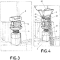
- Figure 3 represents a third step of this method.
- a connector receptacle 5 is engaged to the auxiliary element by means of a ball socket 51 which is connected to the ball joint (covered by the ball socket)of the auxiliary element 4.
- the connector receptacle has a rotational degree of freedom with respect to the auxiliary element, but has no linear degree of freedom with respect to the auxiliary element.
- the ball socket is part of the auxiliary element and the ball joint is part of the connector receptacle.
- Figure 4 represents a fourth step of this method.
- a matching connector 6 is inserted in the connector receptacle 5.
- the connector receptacle 5 comprises a recess 52 so that the connecting cables 60 from the matching connector 6 may pass through the recess 52 and then reach the main connector of the housing.
- the matching connector 6 comprises a first region 61 intended to cooperate with the connector receptacle 5 and a second region 62 comprising the funnel guide 63.
- This first region 61 comprises a rectangular protrusion 64 and the connector receptacle 5 comprises a rectangular housing 53, so that the insertion between the matching connector and the connector receptacle may only be assembled and disassembled in a single direction.
- the matching connector 6 is therefore inserted in the connector receptacle 5 in a detachable way, but with a single linear degree of freedom, since these elements may only be separated in the same direction of insertion. Due to this connection, the matching connector has a rotational degree of freedom with respect to the auxiliary element, and therefore with respect to the housing.
- Figure 5 represents a fifth step of this method.
- a luminous module 7 with a module connector 71 approaches the matching connector 6.
- the module connector 71 is guided by the funnel guide 63 to be coupled to the matching connector 6, thus achieving an electric connection between the module connector 71 and the matching connector 6.
- FIG. 6 represents a farther perspective of this fifth step, showing the automotive luminous device 1.
- the luminous module 7 is approaching at the same time the matching connector 6 and some aiming means 21 located in the housing.
- the mechanical connector 8 of the luminous module 7 is mechanically coupled to the aiming system 21 of the housing 2 and the module connector 71 is also electrically coupled to the matching connector 6, which also belongs to the housing 2.
- This single step is automatic and saves human intervention, while keeps the connecting cables 60 safe from being tangled or trapped, since they do not move during this assembly step.
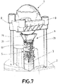
- Figure 7 represents a final step of this method.
- the auxiliary element is screwed into the hollow protrusion 3 (so it is not seen).
- the rectangular housing 53 of the connector receptacle 5, which is engaged to the auxiliary element also descends, being disengaged from the matching connector 6, which remains coupled to the module connector 71 since the force which couples both connectors is stronger than the mere insertion of a rectangular element inside a rectangular housing.
- the luminous module 7 remains connected to the matching connector 6 and is free to be moved by the mechanical connector 8 when required, since the mechanical connector 8 is coupled to the aiming system 21 of the housing.
- the hollow protrusion is a through hole so that it is accessible from both sides, and the step of screwing the auxiliary element is made from the side opposite from the connection between the auxiliary element and the connector receptacle.
- this final step would comprise the step of introducing the auxiliary element inside the hollow protrusion by a force which overcomes the resistance and moves the auxiliary element inside the hollow protrusion so that the matching connector exits from the connector receptacle.
Landscapes
- Engineering & Computer Science (AREA)
- General Engineering & Computer Science (AREA)
- Non-Portable Lighting Devices Or Systems Thereof (AREA)
- Lighting Device Outwards From Vehicle And Optical Signal (AREA)
Abstract
Description
- This invention is related to the field of the manufacturing of automotive luminous devices, and more specifically to the positioning of luminous modules on a luminous device housing.
- Vehicles luminous devices require an increasing number of electric connections to perform new functions, providing a safer and advanced performance.
- A harness of wires is used to make information and electric supply reach each one of the light sources of the luminous device. This harness is distributed in different bundles throughout the housing, because luminous modules must be located in specific positions to fulfil strict regulations.
- Each one of these wires bundles ends with an electrical connector, which is electrically coupled to the luminous module. However, these wires bundles are loose and, since the assembly of the luminous devices is made manually, with reduced visibility and accessibility, the final layout of these bundles after connecting the luminous module is uncertain. This may be dangerous and impact the correct operation of the luminous device.
- Further, current luminous modules sometimes request freedom to rotate or pivot, so these connections cannot be excessively tight.
- The invention provides a solution for this problem by means of method for manufacturing a luminous device according to claim 1. Preferred embodiments of the invention are defined in dependent claims.
- Unless otherwise defined, all terms (including technical and scientific terms) used herein are to be interpreted as is customary in the art. It will be further understood that terms in common usage should also be interpreted as is customary in the relevant art and not in an idealised or overly formal sense unless expressly so defined herein.
- In this text, the term "comprises" and its derivations (such as "comprising", etc.) should not be understood in an excluding sense, that is, these terms should not be interpreted as excluding the possibility that what is described and defined may include further elements, steps, etc.
- In a first inventive aspect, the invention provides a method for manufacturing an automotive luminous device, the method comprising the steps of
providing a housing with a hollow protrusion;
providing an auxiliary element in the hollow protrusion;
providing a connector receptacle in connection with the auxiliary element, so that the connector receptacle has a rotational degree of freedom with respect to the auxiliary element, but has no linear degree of freedom with respect to the auxiliary element;
inserting a matching connector in the connector receptacle in a detachable way, the matching connector further comprising guiding means;
placing a luminous module comprising a module connector, the module connector being helped by the guiding means to be connected to the matching connector, thus achieving an electric connection between the module connector and the matching connector;
moving the connector receptacle so that the matching connector exits from the connector receptacle. - The connector receptacle is connected to the auxiliary element in such a way that the connector receptacle may rotate with respect to the auxiliary element, but may not displace linearly, unless a high separation force is applied. As a result, when the matching connector is inserted in the connector receptacle, the guiding means of the matching connector have a rotational degree of freedom with respect to the housing, so that these guiding means adapt to the position of the module connector while the lighting module approaches the housing for its assembly.
- This method allows a semiautomatic electrical connection between the lighting module and the matching connection, which is previously pre-positioned to the housing in an earlier manufacturing step. The lighting module is safely connected and then the auxiliary elements used to achieve this connection are moved away so that the module connector and the matching connector are freed.
- In some particular embodiments, the luminous module further comprises a mechanical connector which is connected to the housing while the module connector is connected to the matching connector.
- This simultaneous connection is particularly advantageous, since in the same step as the mechanical connection is achieved, electrical connection is also finished, and the movement of the auxiliary elements frees the lighting module so that the module installation is completed.
- In some particular embodiments, the luminous module further comprises a mechanical connector which is connected to an aiming system of the housing while the module connector is connected to the matching connector.
- The use of an aiming system is particularly advantageous, since it may locate the connection point far from the housing, in a location where this connection may be more convenient for the manufacturing process.
- In some particular embodiments, the hollow protrusion is internally threaded, and the step of moving the connector receptacle includes screwing the auxiliary element into the hollow protrusion, so that the connector receptacle moves away from the matching connector.
- The auxiliary element and the connector receptacle are engaged and form an assembly which a rotational degree of freedom. As a consequence, when the auxiliary element is screwed into the hollow protrusion, the connector receptacle also moves with it, and leaves the matching connector in connection with the module connector.
- In some particular embodiments, the hollow protrusion is a through hole so that it is accessible from both sides, and the step of screwing the auxiliary element is made from the side opposite from the connection between the auxiliary element and the connector receptacle.
- The screwing of the auxiliary element may be performed in many ways. One of them is accessing it from a side opposite to the side where the auxiliary element is provided inside the hollow protrusion. This is a good solution, since the through hole is closed by the auxiliary element itself and this auxiliary element, despite being screwed, remains as a watertight sealing for this through hole.
- In some particular embodiments, the hollow protrusion is configured to allow the displacement of the auxiliary element inside the hollow protrusion but offering resistance to the movement, so that the resistance keeps the auxiliary element in place until the step of moving the connector receptacle, when an external force overcomes the resistance and moves the auxiliary element inside the hollow protrusion so that the matching connector exits from the connector receptacle.
- In these embodiments, the auxiliary element is configured to slide along the inner surface of the hollow protrusion. In a first step, the auxiliary element is merely deposited inside the hollow protrusion, and the rest of elements (the connector receptacle and the matching connector) are successively placed on it. Due to the resistive force, the auxiliary element supports these elements without moving. In a further step, the auxiliary element is forced to move further inside the hollow protrusion so that the connector receptacle disengages from the matching connector.
- In some particular embodiments, the auxiliary element and the connector receptacle comprise a ball joint and a ball socket, so that the connection between the auxiliary element and the connector receptacle has a rotational degree of freedom.
- The auxiliary element and the connection receptacle have a mutual engagement which allows the connector receptacle move with a rotational degree of freedom with respect to the auxiliary element, but has no linear degree of freedom. This ball joint-socket arrangement is a good option to achieve this connection. One of the auxiliary element or the connector receptacle comprises the ball joint and the other one comprises the ball socket. In preferred embodiments, the auxiliary element comprises the ball joint and the connection receptacle comprises the ball socket.
- In some particular embodiments,
the matching connector comprises a first region intended to cooperate with the connector receptacle and a second region comprising the guiding means, and
the first region of the matching connector and the connector receptacle comprise a rectangular protrusion and a rectangular housing, so that the insertion between the matching connector and the connector receptacle may only be assembled and disassembled in a single direction. - This way of inserting the matching connector into the connector receptacle in a detachable way is advantageous, since after this insertion, the matching connector is safely engaged to the auxiliary element with a rotational degree of freedom, waiting for the module connector to be connected to it.
- In some particular embodiments, the rectangular housing comprises a recess for connecting cables from the matching connector to pass.
- The matching connector is electrically connected to the main electrical connection of the housing in a previous step. The cables that perform this connection are conducted in a controlled way from the matching connector to this main electrical connection due to the recess.
- In some particular embodiments, the guiding means comprise a funnel shaped guide adapted to guide the module connector towards the matching connector.
- This funnel shaped guide comprised in the matching connector helps the module connector to arrive at the matching connector while the luminous module is being installed in the housing.
- To complete the description and in order to provide for a better understanding of the invention, a set of drawings is provided. Said drawings form an integral part of the description and illustrate an embodiment of the invention, which should not be interpreted as restricting the scope of the invention, but just as an example of how the invention can be carried out. The drawings comprise the following figures:
-
Figure 1a shows a first step of a particular embodiment of a method for manufacturing an automotive luminous device according to the invention. -
Figure 1b shows a first step of a different embodiment of a method for manufacturing an automotive luminous device according to the invention. -
Figure 2 shows a second step of the method illustrated inFigure 1a . -
Figure 3 represents a third step of this method. -
Figure 4 represents a fourth step of this method. -
Figure 5 represents a fifth step of this method. -
Figure 6 represents a farther perspective of this fifth step. -
Figure 7 represents a final step of this method. - The example embodiments are described in sufficient detail to enable those of ordinary skill in the art to embody and implement the systems and processes herein described. It is important to understand that embodiments can be provided in many alternate forms and should not be construed as limited to the examples set forth herein.
- Accordingly, while embodiment can be modified in various ways and take on various alternative forms, specific embodiments thereof are shown in the drawings and described in detail below as examples. There is no intent to limit to the particular forms disclosed. On the contrary, all modifications, equivalents, and alternatives falling within the scope of the appended claims should be included. Elements of the example embodiments are consistently denoted by the same reference numerals throughout the drawings and detailed description where appropriate.
-
Figure 1a shows a first step of a particular embodiment of a method for manufacturing an automotive luminous device according to the invention. - In this figure, a
housing 2 is provided with ahollow protrusion 3. This hollow protrusion has some means to retain an element which is inserted in it. In thisfigure 1a , this means comprise a threadedinner surface 30. -
Figure 1b shows a first step of a different embodiment of a method for manufacturing an automotive luminous device according to the invention. - In this figure, the
housing 2 is also provided with ahollow protrusion 3, and this hollow protrusion has some means to retain an element which is inserted in it. However, in thisfigure 1b , this means comprise a rubberinner surface 31. -
Figure 2 shows a second step of a particular embodiment of a method for manufacturing an automotive luminous device according to the invention. - This figure represents a method which uses the housing of
figure 1a . In this figure, anauxiliary element 4 is placed in thehollow protrusion 3. Since thehollow protrusion 3 has an inner threaded surface, theauxiliary element 4, which is intended to match this threaded surface, comprises a complementary threadedsurface 40. - This auxiliary element also comprises a ball joint 41, which is accessible after the auxiliary element has been introduced into the hollow protrusion.
-
Figure 3 represents a third step of this method. In this figure, aconnector receptacle 5 is engaged to the auxiliary element by means of aball socket 51 which is connected to the ball joint (covered by the ball socket)of theauxiliary element 4. As a consequence, the connector receptacle has a rotational degree of freedom with respect to the auxiliary element, but has no linear degree of freedom with respect to the auxiliary element. As may be obvious, in different embodiments, the ball socket is part of the auxiliary element and the ball joint is part of the connector receptacle. -
Figure 4 represents a fourth step of this method. In this figure, a matchingconnector 6 is inserted in theconnector receptacle 5. Theconnector receptacle 5 comprises arecess 52 so that the connectingcables 60 from the matchingconnector 6 may pass through therecess 52 and then reach the main connector of the housing. - The matching
connector 6 comprises afirst region 61 intended to cooperate with theconnector receptacle 5 and asecond region 62 comprising thefunnel guide 63. Thisfirst region 61 comprises arectangular protrusion 64 and theconnector receptacle 5 comprises arectangular housing 53, so that the insertion between the matching connector and the connector receptacle may only be assembled and disassembled in a single direction. - The matching
connector 6 is therefore inserted in theconnector receptacle 5 in a detachable way, but with a single linear degree of freedom, since these elements may only be separated in the same direction of insertion. Due to this connection, the matching connector has a rotational degree of freedom with respect to the auxiliary element, and therefore with respect to the housing. -
Figure 5 represents a fifth step of this method. Aluminous module 7 with amodule connector 71 approaches the matchingconnector 6. Themodule connector 71 is guided by thefunnel guide 63 to be coupled to the matchingconnector 6, thus achieving an electric connection between themodule connector 71 and the matchingconnector 6. -
Figure 6 represents a farther perspective of this fifth step, showing the automotive luminous device 1. Theluminous module 7 is approaching at the same time the matchingconnector 6 and some aiming means 21 located in the housing. As a consequence, in a single coupling step, themechanical connector 8 of theluminous module 7 is mechanically coupled to the aimingsystem 21 of thehousing 2 and themodule connector 71 is also electrically coupled to the matchingconnector 6, which also belongs to thehousing 2. This single step is automatic and saves human intervention, while keeps the connectingcables 60 safe from being tangled or trapped, since they do not move during this assembly step. -
Figure 7 represents a final step of this method. The auxiliary element is screwed into the hollow protrusion 3 (so it is not seen). As a consequence, therectangular housing 53 of theconnector receptacle 5, which is engaged to the auxiliary element, also descends, being disengaged from the matchingconnector 6, which remains coupled to themodule connector 71 since the force which couples both connectors is stronger than the mere insertion of a rectangular element inside a rectangular housing. As a consequence, theluminous module 7 remains connected to the matchingconnector 6 and is free to be moved by themechanical connector 8 when required, since themechanical connector 8 is coupled to the aimingsystem 21 of the housing. - As may be seen in this figure, the hollow protrusion is a through hole so that it is accessible from both sides, and the step of screwing the auxiliary element is made from the side opposite from the connection between the auxiliary element and the connector receptacle.
- In the method which is according to the embodiment shown in
figure 1b , this final step would comprise the step of introducing the auxiliary element inside the hollow protrusion by a force which overcomes the resistance and moves the auxiliary element inside the hollow protrusion so that the matching connector exits from the connector receptacle.
Claims (10)
- Method for manufacturing an automotive luminous device 1, the method comprising the steps of
providing a housing (2) with a hollow protrusion (3);
providing an auxiliary element (4) in the hollow protrusion (3);
providing a connector receptacle (5) in connection with the auxiliary element (4), so that the connector receptacle (5) has a rotational degree of freedom with respect to the auxiliary element (4), but has no linear degree of freedom with respect to the auxiliary element (4);
inserting a matching connector (6) in the connector receptacle (5) in a detachable way, the matching connector (6) further comprising guiding means (63);
placing a luminous module (7) comprising a module connector (71), the module connector (71) being helped by the guiding means (63) to be connected to the matching connector (6), thus achieving an electric connection between the module connector (71) and the matching connector (6);
moving the connector receptacle (5) so that the matching connector (6) exits from the connector receptacle (5). - Method according to claim 1, wherein the luminous module (7) further comprises a mechanical connector which is connected to the housing while the module connector (71) is connected to the matching connector (6).
- Method according to any of claims 1 or 2, wherein the luminous module (7) further comprises a further mechanical connector (8) which is connected to an aiming system (21) of the housing (2) while the module connector (71) is connected to the matching connector (6).
- Method according to any of the preceding claims, wherein the hollow protrusion (3) is internally threaded, and the step of moving the connector receptacle (5) includes screwing the auxiliary element (4) into the hollow protrusion (3), so that the connector receptacle (5) moves away from the matching connector (6).
- Method according to claim 4, wherein the hollow protrusion (3) is a through hole so that it is accessible from both sides, and the step of screwing the auxiliary element is made from the side opposite from the connection between the auxiliary element (4) and the connector receptacle (5).
- Method according to any of claims 1 to 3, wherein the hollow protrusion (3) is configured to allow the displacement of the auxiliary element (4) inside the hollow protrusion but offering resistance to the movement, so that the resistance keeps the auxiliary element in place until the step of moving the connector receptacle (5), when an external force overcomes the resistance and moves the auxiliary element (4) inside the hollow protrusion (3) so that the matching connector (6) exits from the connector receptacle (5).
- Method according to any of the preceding claims, wherein the auxiliary element (4) and the connector receptacle (5) comprise a ball joint (41) and a ball socket (51), so that the connection between the auxiliary element (4) and the connector receptacle (5) has a rotational degree of freedom.
- Method according to any of the preceding claims, wherein
the matching connector (6) comprises a first region (61) intended to cooperate with the connector receptacle and a second region (62) comprising the guiding means (63), and
the first region (61) of the matching connector (6) and the connector receptacle (5) comprise a rectangular protrusion (64) and a rectangular housing (53), so that the insertion between the matching connector (6) and the connector receptacle (5) may only be assembled and disassembled in a single direction. - Method according to claim 8, wherein the rectangular housing comprises a recess (52) for connecting cables (60) from the matching connector (6) to pass.
- Method according to any of the preceding claims, wherein the guiding means comprise a funnel shaped guide (63) adapted to guide the module connector (71) towards the matching connector (6).
Priority Applications (3)
| Application Number | Priority Date | Filing Date | Title |
|---|---|---|---|
| EP18382575.1A EP3604906A1 (en) | 2018-07-31 | 2018-07-31 | Method for manufacturing an automotive luminous device |
| US16/527,644 US11320121B2 (en) | 2018-07-31 | 2019-07-31 | Method for assembling an adjustable automotive luminous device |
| CN201910706873.7A CN110778971A (en) | 2018-07-31 | 2019-07-31 | Method for producing a lighting device for a motor vehicle |
Applications Claiming Priority (1)
| Application Number | Priority Date | Filing Date | Title |
|---|---|---|---|
| EP18382575.1A EP3604906A1 (en) | 2018-07-31 | 2018-07-31 | Method for manufacturing an automotive luminous device |
Publications (1)
| Publication Number | Publication Date |
|---|---|
| EP3604906A1 true EP3604906A1 (en) | 2020-02-05 |
Family
ID=63449414
Family Applications (1)
| Application Number | Title | Priority Date | Filing Date |
|---|---|---|---|
| EP18382575.1A Withdrawn EP3604906A1 (en) | 2018-07-31 | 2018-07-31 | Method for manufacturing an automotive luminous device |
Country Status (3)
| Country | Link |
|---|---|
| US (1) | US11320121B2 (en) |
| EP (1) | EP3604906A1 (en) |
| CN (1) | CN110778971A (en) |
Citations (8)
| Publication number | Priority date | Publication date | Assignee | Title |
|---|---|---|---|---|
| DE19607798A1 (en) * | 1995-03-03 | 1996-09-05 | Volkswagen Ag | Motor vehicle headlamp |
| KR20020088136A (en) * | 2001-05-17 | 2002-11-27 | 현대자동차주식회사 | Structure for wiring-connection of rear combination lamp for automobile |
| US20090257819A1 (en) * | 2008-04-10 | 2009-10-15 | Burton Technologies, Llc | Push-in connector |
| US20130219694A1 (en) * | 2012-02-29 | 2013-08-29 | GM Global Technology Operations LLC | Lamp socket assembly tool |
| JP2014146465A (en) * | 2013-01-28 | 2014-08-14 | Koito Mfg Co Ltd | Head light for vehicle |
| FR3010771A1 (en) * | 2013-09-16 | 2015-03-20 | Valeo Vision | ELECTRICAL CONNECTION IN A LIGHTING AND / OR SIGNALING DEVICE |
| CN204488626U (en) * | 2014-12-30 | 2015-07-22 | 天津斯坦雷电气有限公司 | A kind of automobile socket seat with auxiliary mounting handle |
| DE102015215696A1 (en) * | 2014-08-18 | 2016-02-18 | Koito Manufacturing Co., Ltd. | Vehicle lighting device |
Family Cites Families (4)
| Publication number | Priority date | Publication date | Assignee | Title |
|---|---|---|---|---|
| JP3704648B2 (en) * | 2002-12-24 | 2005-10-12 | 日本航空電子工業株式会社 | Connector device |
| EP1760392A1 (en) * | 2005-08-29 | 2007-03-07 | Patent-Treuhand-Gesellschaft für elektrische Glühlampen mbH | A mounting structure for LED lighting systems |
| EP3078998A1 (en) * | 2015-04-10 | 2016-10-12 | CCS Technology Inc. | A plug connector to couple a hybrid cable to a receptacle |
| FR3044833A1 (en) * | 2015-12-07 | 2017-06-09 | Valeo Vision | CONNECTION MODULE FOR MOTOR VEHICLE |
-
2018
- 2018-07-31 EP EP18382575.1A patent/EP3604906A1/en not_active Withdrawn
-
2019
- 2019-07-31 US US16/527,644 patent/US11320121B2/en active Active
- 2019-07-31 CN CN201910706873.7A patent/CN110778971A/en active Pending
Patent Citations (8)
| Publication number | Priority date | Publication date | Assignee | Title |
|---|---|---|---|---|
| DE19607798A1 (en) * | 1995-03-03 | 1996-09-05 | Volkswagen Ag | Motor vehicle headlamp |
| KR20020088136A (en) * | 2001-05-17 | 2002-11-27 | 현대자동차주식회사 | Structure for wiring-connection of rear combination lamp for automobile |
| US20090257819A1 (en) * | 2008-04-10 | 2009-10-15 | Burton Technologies, Llc | Push-in connector |
| US20130219694A1 (en) * | 2012-02-29 | 2013-08-29 | GM Global Technology Operations LLC | Lamp socket assembly tool |
| JP2014146465A (en) * | 2013-01-28 | 2014-08-14 | Koito Mfg Co Ltd | Head light for vehicle |
| FR3010771A1 (en) * | 2013-09-16 | 2015-03-20 | Valeo Vision | ELECTRICAL CONNECTION IN A LIGHTING AND / OR SIGNALING DEVICE |
| DE102015215696A1 (en) * | 2014-08-18 | 2016-02-18 | Koito Manufacturing Co., Ltd. | Vehicle lighting device |
| CN204488626U (en) * | 2014-12-30 | 2015-07-22 | 天津斯坦雷电气有限公司 | A kind of automobile socket seat with auxiliary mounting handle |
Also Published As
| Publication number | Publication date |
|---|---|
| US20200041104A1 (en) | 2020-02-06 |
| CN110778971A (en) | 2020-02-11 |
| US11320121B2 (en) | 2022-05-03 |
Similar Documents
| Publication | Publication Date | Title |
|---|---|---|
| US9819120B2 (en) | Connector | |
| EP3383709B1 (en) | Cable conduit device for connection cables of an airbag module, wiring system, airbag module, and steering wheel or vehicle comprising a cable conduit device of said type | |
| DE102009030352A1 (en) | Method for laying and apparatus for guiding and fixing cables of a wiring harness inside a housing of a lighting device of a motor vehicle | |
| EP2567429B1 (en) | Electrical assembly connection for a motor vehicle | |
| KR20130121644A (en) | Connector having protect plate | |
| CN110792981B (en) | Electronic connection assembly, motor vehicle lighting device and method for producing a motor vehicle lighting device | |
| EP3196985B1 (en) | Electrical connection device and method for mounting an electrical connection device | |
| EP3522311B1 (en) | Assisted assembly method and system | |
| DE3544608A1 (en) | Device and method for mounting electrical transmission cables having a connector system for motor vehicles for the purpose of supplying energy and transmitting signals | |
| EP3028349A1 (en) | End position fixing of a plug connection for increasing the vibration resistance | |
| WO2014194997A1 (en) | Electrical connection system for a shock absorber rod | |
| DE112012002049T5 (en) | Interior lighting device for a vehicle | |
| US11320121B2 (en) | Method for assembling an adjustable automotive luminous device | |
| DE202009016970U1 (en) | connecting device | |
| DE102010061185B4 (en) | Locking actuator for an electrical connector | |
| US9356378B1 (en) | Electric connector housing with a terminal interface | |
| WO2012031808A1 (en) | Connection system and accommodation unit for a control device | |
| EP3076492B1 (en) | Electrical connector system with laterally protruding releasing arm | |
| DE202019105026U1 (en) | Connection adapter for a drive device | |
| DE112012002046T5 (en) | Interior lighting device for a vehicle | |
| EP3486553A1 (en) | Automotive lighting device and method for manufacturing an automotive lighting device | |
| US10205278B2 (en) | Connector connecting device | |
| US10128602B2 (en) | Electric connector with a terminal interface | |
| DE102015017192B4 (en) | Cable routing device for connection cables of a gas bag module and wiring, gas bag module and steering wheel or vehicle with such a cable routing device | |
| KR200445865Y1 (en) | Wire harness fixture |
Legal Events
| Date | Code | Title | Description |
|---|---|---|---|
| PUAI | Public reference made under article 153(3) epc to a published international application that has entered the european phase |
Free format text: ORIGINAL CODE: 0009012 |
|
| STAA | Information on the status of an ep patent application or granted ep patent |
Free format text: STATUS: REQUEST FOR EXAMINATION WAS MADE |
|
| 17P | Request for examination filed |
Effective date: 20180731 |
|
| AK | Designated contracting states |
Kind code of ref document: A1 Designated state(s): AL AT BE BG CH CY CZ DE DK EE ES FI FR GB GR HR HU IE IS IT LI LT LU LV MC MK MT NL NO PL PT RO RS SE SI SK SM TR |
|
| AX | Request for extension of the european patent |
Extension state: BA ME |
|
| RIC1 | Information provided on ipc code assigned before grant |
Ipc: B60Q 1/00 20060101ALN20220530BHEP Ipc: F21S 45/00 20180101AFI20220530BHEP |
|
| RIC1 | Information provided on ipc code assigned before grant |
Ipc: B60Q 1/00 20060101ALN20220711BHEP Ipc: F21S 45/00 20180101AFI20220711BHEP |
|
| GRAP | Despatch of communication of intention to grant a patent |
Free format text: ORIGINAL CODE: EPIDOSNIGR1 |
|
| STAA | Information on the status of an ep patent application or granted ep patent |
Free format text: STATUS: GRANT OF PATENT IS INTENDED |
|
| INTG | Intention to grant announced |
Effective date: 20220825 |
|
| STAA | Information on the status of an ep patent application or granted ep patent |
Free format text: STATUS: THE APPLICATION IS DEEMED TO BE WITHDRAWN |
|
| 18D | Application deemed to be withdrawn |
Effective date: 20230105 |
|
| P01 | Opt-out of the competence of the unified patent court (upc) registered |
Effective date: 20230629 |