EP3604860B1 - Pulley structure and method for manufacturing pulley structure - Google Patents
Pulley structure and method for manufacturing pulley structure Download PDFInfo
- Publication number
- EP3604860B1 EP3604860B1 EP18777732.1A EP18777732A EP3604860B1 EP 3604860 B1 EP3604860 B1 EP 3604860B1 EP 18777732 A EP18777732 A EP 18777732A EP 3604860 B1 EP3604860 B1 EP 3604860B1
- Authority
- EP
- European Patent Office
- Prior art keywords
- rotating body
- grease
- pulley structure
- inner rotating
- facing surface
- Prior art date
- Legal status (The legal status is an assumption and is not a legal conclusion. Google has not performed a legal analysis and makes no representation as to the accuracy of the status listed.)
- Active
Links
Images



Classifications
-
- F—MECHANICAL ENGINEERING; LIGHTING; HEATING; WEAPONS; BLASTING
- F02—COMBUSTION ENGINES; HOT-GAS OR COMBUSTION-PRODUCT ENGINE PLANTS
- F02B—INTERNAL-COMBUSTION PISTON ENGINES; COMBUSTION ENGINES IN GENERAL
- F02B63/00—Adaptations of engines for driving pumps, hand-held tools or electric generators; Portable combinations of engines with engine-driven devices
- F02B63/04—Adaptations of engines for driving pumps, hand-held tools or electric generators; Portable combinations of engines with engine-driven devices for electric generators
- F02B63/042—Rotating electric generators
-
- F—MECHANICAL ENGINEERING; LIGHTING; HEATING; WEAPONS; BLASTING
- F02—COMBUSTION ENGINES; HOT-GAS OR COMBUSTION-PRODUCT ENGINE PLANTS
- F02B—INTERNAL-COMBUSTION PISTON ENGINES; COMBUSTION ENGINES IN GENERAL
- F02B67/00—Engines characterised by the arrangement of auxiliary apparatus not being otherwise provided for, e.g. the apparatus having different functions; Driving auxiliary apparatus from engines, not otherwise provided for
- F02B67/04—Engines characterised by the arrangement of auxiliary apparatus not being otherwise provided for, e.g. the apparatus having different functions; Driving auxiliary apparatus from engines, not otherwise provided for of mechanically-driven auxiliary apparatus
- F02B67/06—Engines characterised by the arrangement of auxiliary apparatus not being otherwise provided for, e.g. the apparatus having different functions; Driving auxiliary apparatus from engines, not otherwise provided for of mechanically-driven auxiliary apparatus driven by means of chains, belts, or like endless members
-
- F—MECHANICAL ENGINEERING; LIGHTING; HEATING; WEAPONS; BLASTING
- F16—ENGINEERING ELEMENTS AND UNITS; GENERAL MEASURES FOR PRODUCING AND MAINTAINING EFFECTIVE FUNCTIONING OF MACHINES OR INSTALLATIONS; THERMAL INSULATION IN GENERAL
- F16C—SHAFTS; FLEXIBLE SHAFTS; ELEMENTS OR CRANKSHAFT MECHANISMS; ROTARY BODIES OTHER THAN GEARING ELEMENTS; BEARINGS
- F16C17/00—Sliding-contact bearings for exclusively rotary movement
- F16C17/02—Sliding-contact bearings for exclusively rotary movement for radial load only
-
- F—MECHANICAL ENGINEERING; LIGHTING; HEATING; WEAPONS; BLASTING
- F16—ENGINEERING ELEMENTS AND UNITS; GENERAL MEASURES FOR PRODUCING AND MAINTAINING EFFECTIVE FUNCTIONING OF MACHINES OR INSTALLATIONS; THERMAL INSULATION IN GENERAL
- F16C—SHAFTS; FLEXIBLE SHAFTS; ELEMENTS OR CRANKSHAFT MECHANISMS; ROTARY BODIES OTHER THAN GEARING ELEMENTS; BEARINGS
- F16C33/00—Parts of bearings; Special methods for making bearings or parts thereof
- F16C33/02—Parts of sliding-contact bearings
- F16C33/04—Brasses; Bushes; Linings
- F16C33/20—Sliding surface consisting mainly of plastics
-
- F—MECHANICAL ENGINEERING; LIGHTING; HEATING; WEAPONS; BLASTING
- F16—ENGINEERING ELEMENTS AND UNITS; GENERAL MEASURES FOR PRODUCING AND MAINTAINING EFFECTIVE FUNCTIONING OF MACHINES OR INSTALLATIONS; THERMAL INSULATION IN GENERAL
- F16D—COUPLINGS FOR TRANSMITTING ROTATION; CLUTCHES; BRAKES
- F16D41/00—Freewheels or freewheel clutches
- F16D41/20—Freewheels or freewheel clutches with expandable or contractable clamping ring or band
- F16D41/206—Freewheels or freewheel clutches with expandable or contractable clamping ring or band having axially adjacent coils, e.g. helical wrap-springs
-
- F—MECHANICAL ENGINEERING; LIGHTING; HEATING; WEAPONS; BLASTING
- F16—ENGINEERING ELEMENTS AND UNITS; GENERAL MEASURES FOR PRODUCING AND MAINTAINING EFFECTIVE FUNCTIONING OF MACHINES OR INSTALLATIONS; THERMAL INSULATION IN GENERAL
- F16F—SPRINGS; SHOCK-ABSORBERS; MEANS FOR DAMPING VIBRATION
- F16F15/00—Suppression of vibrations in systems; Means or arrangements for avoiding or reducing out-of-balance forces, e.g. due to motion
- F16F15/10—Suppression of vibrations in rotating systems by making use of members moving with the system
- F16F15/12—Suppression of vibrations in rotating systems by making use of members moving with the system using elastic members or friction-damping members, e.g. between a rotating shaft and a gyratory mass mounted thereon
- F16F15/121—Suppression of vibrations in rotating systems by making use of members moving with the system using elastic members or friction-damping members, e.g. between a rotating shaft and a gyratory mass mounted thereon using springs as elastic members, e.g. metallic springs
- F16F15/1216—Torsional springs, e.g. torsion bar or torsionally-loaded coil springs
-
- F—MECHANICAL ENGINEERING; LIGHTING; HEATING; WEAPONS; BLASTING
- F16—ENGINEERING ELEMENTS AND UNITS; GENERAL MEASURES FOR PRODUCING AND MAINTAINING EFFECTIVE FUNCTIONING OF MACHINES OR INSTALLATIONS; THERMAL INSULATION IN GENERAL
- F16F—SPRINGS; SHOCK-ABSORBERS; MEANS FOR DAMPING VIBRATION
- F16F15/00—Suppression of vibrations in systems; Means or arrangements for avoiding or reducing out-of-balance forces, e.g. due to motion
- F16F15/10—Suppression of vibrations in rotating systems by making use of members moving with the system
- F16F15/12—Suppression of vibrations in rotating systems by making use of members moving with the system using elastic members or friction-damping members, e.g. between a rotating shaft and a gyratory mass mounted thereon
- F16F15/121—Suppression of vibrations in rotating systems by making use of members moving with the system using elastic members or friction-damping members, e.g. between a rotating shaft and a gyratory mass mounted thereon using springs as elastic members, e.g. metallic springs
- F16F15/123—Wound springs
-
- F—MECHANICAL ENGINEERING; LIGHTING; HEATING; WEAPONS; BLASTING
- F16—ENGINEERING ELEMENTS AND UNITS; GENERAL MEASURES FOR PRODUCING AND MAINTAINING EFFECTIVE FUNCTIONING OF MACHINES OR INSTALLATIONS; THERMAL INSULATION IN GENERAL
- F16H—GEARING
- F16H55/00—Elements with teeth or friction surfaces for conveying motion; Worms, pulleys or sheaves for gearing mechanisms
- F16H55/32—Friction members
- F16H55/36—Pulleys
-
- F—MECHANICAL ENGINEERING; LIGHTING; HEATING; WEAPONS; BLASTING
- F16—ENGINEERING ELEMENTS AND UNITS; GENERAL MEASURES FOR PRODUCING AND MAINTAINING EFFECTIVE FUNCTIONING OF MACHINES OR INSTALLATIONS; THERMAL INSULATION IN GENERAL
- F16H—GEARING
- F16H57/00—General details of gearing
- F16H57/04—Features relating to lubrication or cooling or heating
- F16H57/0463—Grease lubrication; Drop-feed lubrication
- F16H57/0464—Grease lubrication
-
- F—MECHANICAL ENGINEERING; LIGHTING; HEATING; WEAPONS; BLASTING
- F16—ENGINEERING ELEMENTS AND UNITS; GENERAL MEASURES FOR PRODUCING AND MAINTAINING EFFECTIVE FUNCTIONING OF MACHINES OR INSTALLATIONS; THERMAL INSULATION IN GENERAL
- F16H—GEARING
- F16H57/00—General details of gearing
- F16H57/04—Features relating to lubrication or cooling or heating
- F16H57/0467—Elements of gearings to be lubricated, cooled or heated
- F16H57/0469—Bearings or seals
- F16H57/0471—Bearing
-
- F—MECHANICAL ENGINEERING; LIGHTING; HEATING; WEAPONS; BLASTING
- F16—ENGINEERING ELEMENTS AND UNITS; GENERAL MEASURES FOR PRODUCING AND MAINTAINING EFFECTIVE FUNCTIONING OF MACHINES OR INSTALLATIONS; THERMAL INSULATION IN GENERAL
- F16H—GEARING
- F16H57/00—General details of gearing
- F16H57/04—Features relating to lubrication or cooling or heating
- F16H57/048—Type of gearings to be lubricated, cooled or heated
- F16H57/0487—Friction gearings
- F16H57/0489—Friction gearings with endless flexible members, e.g. belt CVTs
-
- F—MECHANICAL ENGINEERING; LIGHTING; HEATING; WEAPONS; BLASTING
- F16—ENGINEERING ELEMENTS AND UNITS; GENERAL MEASURES FOR PRODUCING AND MAINTAINING EFFECTIVE FUNCTIONING OF MACHINES OR INSTALLATIONS; THERMAL INSULATION IN GENERAL
- F16C—SHAFTS; FLEXIBLE SHAFTS; ELEMENTS OR CRANKSHAFT MECHANISMS; ROTARY BODIES OTHER THAN GEARING ELEMENTS; BEARINGS
- F16C19/00—Bearings with rolling contact, for exclusively rotary movement
- F16C19/02—Bearings with rolling contact, for exclusively rotary movement with bearing balls essentially of the same size in one or more circular rows
- F16C19/04—Bearings with rolling contact, for exclusively rotary movement with bearing balls essentially of the same size in one or more circular rows for radial load mainly
- F16C19/06—Bearings with rolling contact, for exclusively rotary movement with bearing balls essentially of the same size in one or more circular rows for radial load mainly with a single row or balls
-
- F—MECHANICAL ENGINEERING; LIGHTING; HEATING; WEAPONS; BLASTING
- F16—ENGINEERING ELEMENTS AND UNITS; GENERAL MEASURES FOR PRODUCING AND MAINTAINING EFFECTIVE FUNCTIONING OF MACHINES OR INSTALLATIONS; THERMAL INSULATION IN GENERAL
- F16C—SHAFTS; FLEXIBLE SHAFTS; ELEMENTS OR CRANKSHAFT MECHANISMS; ROTARY BODIES OTHER THAN GEARING ELEMENTS; BEARINGS
- F16C21/00—Combinations of sliding-contact bearings with ball or roller bearings, for exclusively rotary movement
-
- F—MECHANICAL ENGINEERING; LIGHTING; HEATING; WEAPONS; BLASTING
- F16—ENGINEERING ELEMENTS AND UNITS; GENERAL MEASURES FOR PRODUCING AND MAINTAINING EFFECTIVE FUNCTIONING OF MACHINES OR INSTALLATIONS; THERMAL INSULATION IN GENERAL
- F16C—SHAFTS; FLEXIBLE SHAFTS; ELEMENTS OR CRANKSHAFT MECHANISMS; ROTARY BODIES OTHER THAN GEARING ELEMENTS; BEARINGS
- F16C2361/00—Apparatus or articles in engineering in general
- F16C2361/63—Gears with belts and pulleys
-
- F—MECHANICAL ENGINEERING; LIGHTING; HEATING; WEAPONS; BLASTING
- F16—ENGINEERING ELEMENTS AND UNITS; GENERAL MEASURES FOR PRODUCING AND MAINTAINING EFFECTIVE FUNCTIONING OF MACHINES OR INSTALLATIONS; THERMAL INSULATION IN GENERAL
- F16C—SHAFTS; FLEXIBLE SHAFTS; ELEMENTS OR CRANKSHAFT MECHANISMS; ROTARY BODIES OTHER THAN GEARING ELEMENTS; BEARINGS
- F16C33/00—Parts of bearings; Special methods for making bearings or parts thereof
- F16C33/02—Parts of sliding-contact bearings
- F16C33/04—Brasses; Bushes; Linings
- F16C33/20—Sliding surface consisting mainly of plastics
- F16C33/201—Composition of the plastic
-
- F—MECHANICAL ENGINEERING; LIGHTING; HEATING; WEAPONS; BLASTING
- F16—ENGINEERING ELEMENTS AND UNITS; GENERAL MEASURES FOR PRODUCING AND MAINTAINING EFFECTIVE FUNCTIONING OF MACHINES OR INSTALLATIONS; THERMAL INSULATION IN GENERAL
- F16D—COUPLINGS FOR TRANSMITTING ROTATION; CLUTCHES; BRAKES
- F16D2300/00—Special features for couplings or clutches
- F16D2300/06—Lubrication details not provided for in group F16D13/74
-
- F—MECHANICAL ENGINEERING; LIGHTING; HEATING; WEAPONS; BLASTING
- F16—ENGINEERING ELEMENTS AND UNITS; GENERAL MEASURES FOR PRODUCING AND MAINTAINING EFFECTIVE FUNCTIONING OF MACHINES OR INSTALLATIONS; THERMAL INSULATION IN GENERAL
- F16D—COUPLINGS FOR TRANSMITTING ROTATION; CLUTCHES; BRAKES
- F16D2300/00—Special features for couplings or clutches
- F16D2300/12—Mounting or assembling
-
- F—MECHANICAL ENGINEERING; LIGHTING; HEATING; WEAPONS; BLASTING
- F16—ENGINEERING ELEMENTS AND UNITS; GENERAL MEASURES FOR PRODUCING AND MAINTAINING EFFECTIVE FUNCTIONING OF MACHINES OR INSTALLATIONS; THERMAL INSULATION IN GENERAL
- F16F—SPRINGS; SHOCK-ABSORBERS; MEANS FOR DAMPING VIBRATION
- F16F2230/00—Purpose; Design features
- F16F2230/04—Lubrication
-
- F—MECHANICAL ENGINEERING; LIGHTING; HEATING; WEAPONS; BLASTING
- F16—ENGINEERING ELEMENTS AND UNITS; GENERAL MEASURES FOR PRODUCING AND MAINTAINING EFFECTIVE FUNCTIONING OF MACHINES OR INSTALLATIONS; THERMAL INSULATION IN GENERAL
- F16H—GEARING
- F16H55/00—Elements with teeth or friction surfaces for conveying motion; Worms, pulleys or sheaves for gearing mechanisms
- F16H55/32—Friction members
- F16H55/36—Pulleys
- F16H2055/366—Pulleys with means providing resilience or vibration damping
-
- F—MECHANICAL ENGINEERING; LIGHTING; HEATING; WEAPONS; BLASTING
- F16—ENGINEERING ELEMENTS AND UNITS; GENERAL MEASURES FOR PRODUCING AND MAINTAINING EFFECTIVE FUNCTIONING OF MACHINES OR INSTALLATIONS; THERMAL INSULATION IN GENERAL
- F16H—GEARING
- F16H57/00—General details of gearing
- F16H57/04—Features relating to lubrication or cooling or heating
- F16H57/041—Coatings or solid lubricants, e.g. anti-seize layers or pastes
Definitions
- the present invention relates to a pulley structure having a spring accommodation space formed between two rotating bodies, and a method for manufacturing the pulley structure.
- the pulley structure described in PTL 1 includes: an outer rotating body around which a belt is to be wound; an inner rotating body provided radially inward on the outer rotating body and relatively rotatable with respect to the outer rotating body; a torsion coil spring disposed in spring accommodation space formed between the two rotating bodies; and the like.
- the pulley structure has a clutch mechanism that transmits or blocks torque between the outer rotating body and the inner rotating body via the torsion coil spring.
- the two rotating bodies are made of metal, when rust is generated and interposed between the torsion coil spring and the rotating bodies, the function of the clutch mechanism and the like may be reduced and the life may be shortened. Therefore, a coating for rust prevention is applied to several portions.
- the coating may be peeled off, so that a grease containing a rust inhibitor is used instead of the coating. More specifically, when assembling the pulley structure, the grease is put into the spring accommodation space in a pasty lump state.
- the temperature in the spring accommodation space is raised by running the pulley structure in, for example, an operation test of the alternator, and the temperature of the grease is raised to lower the viscosity.
- the pulley structure is made to rotate in this state, the rust inhibitor is diffused to a portion of the two rotating bodies facing the spring accommodation space by centrifugal force and the like. In this way, compared to the case where the rust inhibitor is adhered to the entire region facing the spring accommodation space one by one, the labor is significantly reduced, and the use amount of rust inhibitor can be minimized.
- the grease When the grease is simply put into the spring accommodation space in a lump state, the grease may be in a state of coming into contact with only an unspecified portion of the spring accommodation space. In this case, heat is less likely to be transferred to the grease due to reasons such as a small heat-transfer area and thus, the viscosity is less likely to decrease. Therefore, when the pulley structure is rotated, it may be difficult to diffuse the grease to every corner of the region facing the spring accommodation space of the two rotating bodies.
- An object of the present invention is to facilitate diffusion of the rust inhibitor over the entire region facing the spring accommodation space.
- the pulley structure in a first aspect of the present invention is a pulley structure to be connected to an accessory machine of an engine and to which power of the engine is to be transmitted via a belt, the pulley structure including: a cylindrical outer rotating body around which the belt is to be wound; an inner rotating body provided radially inward on the outer rotating body and relatively rotatable with respect to the outer rotating body; and a torsion coil spring disposed in a spring accommodation space formed between the outer rotating body and the inner rotating body, in which at least in a state where the pulley structure is not yet operated once, a grease containing a rust inhibitor is applied to a facing surface of the inner rotating body, facing an inner circumferential surface of the torsion coil spring.
- the grease containing a rust inhibitor in a state where the pulley structure is not yet operated once, the grease containing a rust inhibitor is in a state of being applied to the facing surface of the inner rotating body, facing the inner circumferential surface of the torsion coil spring.
- the contact area with the inner rotating body is larger as compared to the case where the grease is simply put in the spring accommodation space in a lump state, heat of the inner rotating body is likely to be transferred to the grease during the operation test of the accessory machine and the like, the temperature of the grease is likely to be raised, and the viscosity is likely to decrease.
- the rust inhibitor can be made to be easily diffused in the entire region facing the spring accommodation space.
- the grease has a thickness of 2 mm or less on the facing surface.
- the thickness of the grease on the facing surface is preferably 2 mm or less.
- the grease in the pulley structure according to a third aspect of the present invention, in the first or second aspect, has an adhering area to the facing surface being 4% or more of the area of the facing surface.
- the adhering area of the grease to the facing surface is 4% or more of the area of the facing surface. That is, since the heat-transfer area of the grease is large, heat of the inner rotating body is easily transferred to the grease.
- the grease is applied on the facing surface along a rotation axis direction of the inner rotating body.
- the grease In the radial direction, since the centrifugal force due to the rotation of the inner rotating body acts on the grease during the operation test of the accessory machine and the like, the grease is likely to be diffused to outside. However, in the rotation axis direction, since no particularly large force acts on the grease, the grease is relatively less likely to be diffused. In this aspect, since the grease is applied on the facing surface along the rotation axis direction of the inner rotating body, the grease can be easily diffused in the rotation axis direction.
- the grease is applied only to the facing surface of the inner rotating body among surfaces forming the spring accommodation space.
- the grease is applied only to the facing surface of the inner rotating body among the surfaces forming the spring accommodation space. Therefore, it is possible to efficiently diffuse the grease in the spring accommodation space by the rotation of the inner rotating body while reducing the labor as compared to the case where the grease is also applied to other places.
- the pulley structure according to a sixth aspect of the present invention in any one of the first to fifth aspects, includes a sliding bearing interposed between the inner rotating body and an end portion of the outer rotating body in a rotation axis direction.
- the grease is applied to the facing surface of the inner rotating body, the grease is likely to be diffused into both the inner rotating body and the outer rotating body. Therefore, even in the case where the grease is not applied to the outer rotating body, the rust inhibitor is spread to the end portion of the outer rotating body in the rotation axis direction, and the generation of rust in the portion can be suppressed. Therefore, the bearing function can be maintained for a long period of time while suppressing a decrease in production efficiency.
- the sliding bearing is formed of a resin composition containing polytetramethylene adipamide as a base resin, and the resin composition contains a reinforcing material containing aramid fibers.
- the bearing function can be maintained for a longer period of time.
- the accessory machine is an alternator that generates electricity by the rotation of a drive shaft.
- the method for manufacturing a pulley structure according to a ninth aspect of the present invention is a method for manufacturing a pulley structure to be connected to an accessory machine of an engine and to which power of the engine is to be transmitted via a belt
- the pulley structure includes: a cylindrical outer rotating body around which the belt is to be wound; an inner rotating body provided radially inward on the outer rotating body and relatively rotatable with respect to the outer rotating body; and a torsion coil spring disposed in a spring accommodation space formed between the outer rotating body and the inner rotating body
- the method includes: applying a grease containing a rust inhibitor to a facing surface of the inner rotating body, facing an inner circumferential surface of the torsion coil spring.
- the contact area between the grease and the inner rotating body becomes larger as compared to the case where the grease is simply put into the spring accommodation space in a lump state. Therefore, heat of the inner rotating body is likely to be transferred to the grease during the operation test of the accessory machine and the like.
- the grease is applied to the facing surface of the inner rotating body disposed radially inward among the surfaces forming the spring accommodation space, the grease is likely to spread over the inner rotating body, and the centrifugal force due to the rotation of the inner rotating body acts on the grease, so that the grease is also likely to be diffused to the outer side in the radial direction.
- the method for manufacturing a pulley structure according to a tenth aspect of the present invention includes: after applying of the grease, connecting the pulley structure to the accessory machine, and transmitting a power of a drive source to the pulley structure via the belt to operate the pulley structure.
- the pulley structure is actually connected to the accessory machine, and the power of the drive source is transmitted to the pulley structure via the belt to operate the pulley structure.
- the grease can be diffused to the surfaces forming the spring accommodation space due to the temperature rise of the spring accommodation space with the rotation operation of the pulley structure, the centrifugal force acting on the grease by the rotation of the inner rotating body, and the like.
- the method for manufacturing the pulley structure according to the eleventh aspect of the present invention includes, in the ninth or tenth aspect, mounting the torsion coil spring on the inner rotating body, then, inserting a nozzle of discharging the grease into a gap in the radial direction between the torsion coil spring and the inner rotating body from one side in a rotation axis direction of the inner rotating body, and applying the grease to the facing surface.
- the nozzle is inserted into the gap between the torsion coil spring and the inner rotating body and the grease is applied to the facing surface. Accordingly, it is possible to prevent the grease from adhering to the torsion coil spring.
- the grease is discharged from a discharge port while moving the nozzle from the other side to the one side in the rotation axis direction.
- the grease since the grease is applied to the facing surface while the nozzle is simply drawn out from the other side to the one side, that is, toward the side where the nozzle is inserted, in the rotation axis direction, the grease can be easily applied.
- the grease is applied only to the facing surface of the inner rotating body among surfaces forming the spring accommodation space.
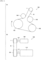
- FIG. 1 is a front view of the belt power-transmission mechanism 100, and (b) of FIG. 1 is a side view thereof.
- the belt power-transmission mechanism 100 includes, for example: a crank pulley 101 connected to a crankshaft 111 of an engine 110 of an automobile or the like; a pulley structure 1 connected to a drive shaft 121 of an alternator 120 ("accessory machine" of the present invention); an AC pulley 102 connected to an air conditioner compressor, which is not illustrated; a WP pulley 103 connected to a water pump, which is not illustrated; and a belt B (V-ribbed belt) wound around these pulleys. Each of the pulleys is rotatably supported.
- An auto-tensioner 104 is provided in the belt span between the crank pulley 101 and the pulley structure 1. The output of the engine 110 is transmitted clockwise from the crank pulley 101 to the pulley structure 1, the WP pulley 103, and the AC pulley 102 via the belt B, and the respective accessory machines are driven.
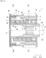
- FIG. 2 is a cross-sectional view of the finished pulley structure 1.
- FIG. 3 is a cross-sectional view taken along the line III-III in FIG. 2 .
- FIG. 4 is a cross-sectional view taken along the line IV-IV in FIG. 2 .
- the direction in which the pulley structure 1 rotates is defined as a circumferential direction.
- the radial direction of the outer rotating body 2 to be described later is defined as a radial direction.
- the pulley structure 1 is mainly connected to the alternator 120 that generates AC electricity by the rotation of the drive shaft 121.
- the pulley structure 1 includes: an outer rotating body 2 around which the belt B is to be wound; an inner rotating body 3 provided inside the outer rotating body 2 and connected to the driving shaft 121 of the alternator; a torsion coil spring 4 (hereinafter, simply referred to as "spring 4") disposed between the outer rotating body 2 and the inner rotating body 3; and the like.
- the outer rotating body 2 is a substantially cylindrical member in which a through hole penetrating in the front-rear direction is formed, and is, for example, a metal member made of carbon steel material such as S45C and the like. As illustrated in FIG. 2 , the belt B is wound around the outer circumferential surface of the outer rotating body 2. The outer rotating body 2 is configured to rotate around a rotation axis R by applying torque via the belt B. On an inner circumference of a rear end portion of the outer rotating body 2, a pressure contact surface 21 with which an outer circumferential surface 41 of a rear end portion of a spring 4 to be described later comes into contact is formed.
- An abutting surface 22 that abuts the spring 4 when it deforms to expand the diameter is formed in front of the pressure contact surface 21.
- the abutting surface 22 is formed radially outward of the pressure contact surface 21.
- a portion between the pressure contact surface 21 and the abutting surface 22 is chamfered.
- a bearing-interposing surface 23 in which a sliding bearing 7 to be described later is interposed is formed in front of the abutting surface 22.
- the bearing-interposing surface 23 is formed radially outward of the abutting surface 22.
- a portion between the abutting surface 22 and the bearing-interposing surface 23 is chamfered.
- An end cap 5 for covering an opening portion in the front of the outer rotating body 2 is attached to a front end portion of the outer rotating body 2.
- a rust-proof coating (e.g., cationic electrodeposition coating) is applied to the outer circumferential surface of the outer rotating body 2, both end surfaces in the axial direction, and the chamfered portions.
- no coating is applied to portions other than the chamfered portions among the inner circumferential surface of the through hole of the outer rotating body 2 (the pressure contact surface 21, the abutting surface 22, the bearing-interposing surface 23, etc.).
- the coating it is necessary to consider to optimize the dimension (size of the chamfer) of a corner portion 24 and the like, where a coating material is difficult to attach, on the outer circumferential surface of the outer rotating body 2 depending on the coating material or the coating method, to thereby enhance the adhesion of the coating film to the corner portion 24.
- the coating film may be peeled off from the corner portion 24 as a starting portion.
- the rust grows on the interface between the coating film and the base (outer rotating body 2), and the rust liberated from the corroded portion enters the inside of the spring accommodation space 8 to be described later (particularly, a place where the sliding bearing 7 is disposed).
- the corner portion 24 be, for example, an R surface having a radius of curvature of approximately 0.8 mm or more, or a C surface.
- the inner rotating body 3 is a metal member having a substantially cylindrical shape, and is, for example, a metal member made of carbon steel material such as S45C and the like. As illustrated in FIG. 2 , the inner rotating body 3 is provided radially inward on the outer rotating body 2 and is configured to be relatively rotatable with respect to the outer rotating body 2 around a common rotation axis R with the outer rotating body 2. The above-described coating is not applied to the inner rotating body 3.
- the inner rotating body 3 includes: a cylindrical main body 31; an outer cylindrical portion 32 disposed radically outward on the front end portion of the cylindrical main body 31; a connection portion 33 connecting the cylindrical main body 31 and the outer cylindrical portion 32; and the like.
- the cylindrical main body 31 is connected to the drive shaft 121 of the alternator.
- a press-fit surface 38 for press-fitting a rolling bearing 6 to be described later is formed at a rear end portion of the cylindrical main body 31.
- a facing surface 34 facing an inner circumferential surface 42 of the spring 4 to be described later is formed in front of the press-fit surface 38.
- the facing surface 34 is formed radially outward on the press-fit surface 38.
- a contact surface 35 that comes into contact with the inner circumferential surface of the spring 4 is formed in front of the facing surface 34.
- the contact surface 35 is formed radially outward on the facing surface 34.
- the outer cylindrical portion 32 is a cylindrical portion disposed radially outward on the front end portion of the cylindrical main body 31.
- the outer cylindrical portion 32 extends rearward to the extent not to interfere with the outer rotating body 2.
- An inner diameter of the outer cylindrical portion 32 is larger than a diameter of the pressure contact surface 21 of the outer rotating body 2.
- the connection portion 33 is formed radially outward on the front end portion of the cylindrical main body 31 and is an annular portion connecting the cylindrical main body 31 and the outer cylindrical portion 32.
- An end surface 36 is formed between the cylindrical main body 31 and the outer cylindrical portion 32 at the front end portion of the inner rotating body 3 (see FIG. 3 ).
- the end surface 36 faces a front end surface 49 of the spring 4 to be described later in the circumferential direction.
- a projection 37 projecting radially inward on the outer cylindrical portion 32 is formed on the inner circumferential surface of the outer cylindrical portion 32 (see FIG. 3 ).
- the projection 37 is formed in the vicinity of a position approximately 90° apart from the end surface 36 in the circumferential direction.
- a rolling bearing 6 is interposed between the inner circumferential surface of the rear end portion of the outer rotating body 2 and an outer circumferential surface of the rear end portion of the cylindrical main body 31 of the inner rotating body 3.
- a sliding bearing 7 is interposed between the inner circumferential surface of the front end portion of the outer rotating body 2 and the outer circumferential surface of the outer cylindrical portion 32 of the inner rotating body 3.
- the outer rotating body 2 and the inner rotating body 3 are relatively rotatable by the rolling bearing 6 and the sliding bearing 7.
- the rolling bearing 6 is, for example, a contact seal type hermetic ball bearing.
- the sliding bearing 7 is, for example, a C-shaped member having elasticity and formed of a resin composition containing a resin of polytetramethylene adipamide (nylon 46) as a base resin (main component).
- the resin composition may contain a fibrous reinforcing material having aramid fibers.
- the sliding bearing 7 is mounted on the outer cylindrical portion 32 of the inner rotating body 3 in a state where the diameter thereof is made slightly expand, and is in close contact with the outer cylindrical portion 32 by a self-elastic-restoring force.
- a gap of approximately 0.1 mm in the radial direction is formed between the sliding bearing 7 and the bearing-interposing surface 23 of the outer rotating body 2. The gap allows air to pass therethrough.
- a spring accommodation space 8 for accommodating the spring 4 is formed between the outer rotating body 2 and the inner rotating body 3.
- the spring accommodation space 8 is a space defined by the inner circumferential surface of the outer rotating body 2, the inner circumferential surface of the outer cylindrical portion 32 of the inner rotating body 3, the outer circumferential surface of the cylindrical main body 31, the rear surface of the connection portion 33, and the front surface of the rolling bearing 6.
- rust may be generated in portions of the outer rotating body 2 and the inner rotating body 3 where the coating is not performed. Due to the rust, portions of the outer rotating body 2 and the inner rotating body 3, which frequently comes into contact with the spring 4 (e.g., the pressure contact surface 21, the abutting surface 22, etc.), the sliding bearing 7 and the like are worn, and the life of the pulley structure 1 may be shortened. Therefore, a grease containing a rust inhibitor is sealed in the spring accommodation space 8 of the pulley structure 1.
- the grease is pasty at normal temperature and contains a base oil which is a rust inhibitor and a thickener that increases the consistency (hardness) of the base oil.
- the base oil is, for example, an ester oil (synthetic oil).
- As the thickener for example, use can be made of a urea compound having excellent heat resistance.
- the grease has a consistency comparable to JIS classification No. 2 to No. 3 at 25°C (the test method is in accordance with JIS K 2220: 2103).
- the content of the thickener is preferably 5 to 40 mass% based on the total amount of the grease.
- the grease preferably has a kinematic viscosity of approximately 100 mm 2 /s at 40°C (the test method is in accordance with ASTM D 7042-14: 2014).
- the grease preferably has a specific gravity of approximately 0.97.
- the grease is diffused over the entire surfaces forming the spring accommodation space 8. The grease is also sealed inside the rolling bearing 6.
- the grease is applied to the facing surface 34 of the inner rotating body 3 in a state in which the pulley structure 1 is not yet operated once such that the grease is likely to be diffused over the entire surfaces of the outer rotating body 2 and the inner rotating body 3, forming the spring accommodation space 8. Details will be described later.
- the spring 4 is a torsion coil spring formed by spirally winding a spring wire.
- the spring wire material of the spring 4 for example, an oil-tempered wire for a spring (in accordance with JIS G 3560: 1994) can be used.
- the spring 4 is wound leftward (counterclockwise from the front end toward the rear end).
- the spring 4 has a substantially constant diameter over the entire length in a state in which the outer rotating body 2 and the inner rotating body 3 are not rotating.
- the spring 4 is interposed between the rear surface of the connection portion 33 of the inner rotating body 3 and the front surface of the rolling bearing , and thus, is accommodated in the spring accommodation space 8 in a state slightly compressed in the axial direction.
- the spring wire of the spring 4 has a rectangular cross-sectional shape, for example.
- an outer circumferential surface 41 and an inner circumferential surface 42 of the spring 4 are substantially parallel to the rotation axis R of the outer rotating body 2.
- the spring 4 has: a rear end side region 43 in which the outer circumferential surface 41 comes into contact with the pressure contact surface 21 of the outer rotating body 2, in a rear end portion; and a front end side region 44 in which the inner circumferential surface 42 comes into contact with the contact surface 35 of the inner rotating body 3, in a front end portion.
- the rear end side region 43 is a region of one round or more (360° or more around the rotation axis) from the rear end of the spring 4. In a state where the outer rotating body 2 and the inner rotating body 3 are not rotating, the rear end side region 43 is accommodated in the spring accommodation space 8 in a state where its diameter is slightly reduced. The outer circumferential surface 41 of the rear end side region 43 is pressed against the pressure contact surface 21 by the self-elastic-restoring force in the radial direction of the spring 4 (see FIG. 2 and FIG. 4 ).
- the front end side region 44 is a region of one round or more (360° or more around the rotation axis) from the front end of the spring 4. In a state where the outer rotating body 2 and the inner rotating body 3 are not rotating, the front end side region 44 is accommodated in the spring accommodation space 8 in a state where the diameter thereof slightly expands. The inner circumferential surface 42 of the front end side region 44 is pressed against the contact surface 35 (see FIG. 2 and FIG. 3 ).
- the front end side region 44 is composed of three portions. That is, as illustrated in FIG. 3 , the front end side region 44 includes: a first portion 46 on the front end side (the same direction as the arrow in FIG.
- the outer rotating body 2 starts rotating relatively with respect to the inner rotating body 3 in the forward direction.
- the outer circumferential surface 41 of the rear end side region 43 of the spring 4 is pressed against the pressure contact surface 21 of the outer rotating body 2 (see FIG. 4 )
- the rear end side region 43 of the spring 4 moves together with the pressure contact surface 21 towards the forward direction and rotates in the forward direction relatively with respect to the inner rotating body 3.
- the spring 4 undergoes a torsional deformation in the diameter expansion direction (hereinafter, simply referred to as diameter expansion deformation).
- the pressure contact force of the rear end side region 43 of the spring 4 against the pressure contact surface 21 increases as the torsional angle of the spring 4 in the diameter expansion direction increases.
- the torsional angle of the spring 4 in the diameter expansion direction is less than a predetermined angle (e.g., 3°)
- a predetermined angle e.g. 3°
- the largest torsional stress is generated in the second portion 47 of the front end side region 44 of the spring 4, and the second portion 47 is most likely to undergo a diameter expansion deformation.
- the inner circumferential surface 42 of the second portion 47 is separated from the contact surface 35 due to the diameter expansion deformation when the torsional angle of the spring 4 in the diameter expansion direction increases.
- the outer circumferential surface of the second portion 47 abuts against the projection 37 and the diameter expansion deformation of the second portion 47 is restricted at substantially the same time when the second portion 47 is separated from the contact surface 35 or at the time when the torsional angle of the spring 4 in the diameter expansion direction further increases.
- the pressure contact force of the third portion 48 with respect to the contact surface 35 becomes substantially zero at the same time when the second portion 47 abuts against the projection 37, or at the time when the torsional angle of the spring 4 in the diameter expansion direction further increases. Furthermore, the third portion 48 is separated from the contact surface 35 due to diameter expansion deformation when the torsional angle further increases. At this time, the diameter expansion deformation of the front end side region 44 of the spring 4 is restricted by the projection 37, and the front end side region 44 is maintained in an arc shape, that is, a shape that is easily slidable with respect to the projection 37.
- the rotational speed of the outer rotating body 2 is smaller than the rotational speed of the inner rotating body 3 (i.e., when the outer rotating body 2 decelerates)
- the outer rotating body 2 rotates in the opposite direction (opposite to the direction of the arrows in FIG. 3 and FIG. 4 ) relatively with respect to the inner rotating body 3.
- the rear end side region 43 of the spring 4 moves together with the pressure contact surface 21 and rotates relative with respect to the inner rotating body 3. Accordingly, the spring 4 undergoes a torsional deformation in the diameter reduction direction (hereinafter, simply referred to as "diameter reduction deformation").
- the pressure contact force of the rear end side region 43 with respect to the pressure contact surface 21 slightly decreases as compared to the case where the torsional angle is zero, but the rear end side region 43 presses against the pressure contact surface 21. Furthermore, the pressure contact force of the front end side region 44 with respect to the contact surface 35 is slightly increased as compared to the case where the torsional angle is zero.
- a predetermined angle e.g. 10°
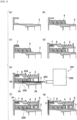
- the spring 4 is press-fitted into the inner rotating body 3 (see (a) of FIG. 5 ) from the rear (see (b) of FIG. 5 ).
- the sliding bearing 7 is mounted on the front end portion of the inner rotating body 3 (see (c) of FIG. 5 ), and the outer rotating body 2 is mounted on the inner rotating body 3 from the rear (see (d) of FIG. 5 ).
- the dispenser 201 includes a main body 202 and a nozzle 203 extending from the main body 202, and is configured to be able to apply the grease to an object by measuring the grease and discharging the measured grease from the nozzle 203.
- the nozzle 203 has a diameter that can be inserted between the facing surface 34 of the inner rotating body 3 and the inner circumferential surface 42 of the spring 4, and a discharge port 204 from which the grease is discharged is formed at its tip end portion.
- the discharge port 204 is inclined obliquely with respect to the direction in which the nozzle 203 extends.
- the amount of the grease required is the minimum amount necessary for forming an oil film on the entire surfaces of the outer rotating body 2 and the inner rotating body 3 on which the coating is not applied, among the surfaces forming the spring accommodation space 8.
- the amount of the grease is approximately 0.2 g (volume is approximately 0.2 cm 3 ).
- the nozzle 203 of the dispenser 201 is inserted between the facing surface 34 of the inner rotating body and the inner circumferential surface 42 of the spring 4 from the rear of the inner rotating body 3.
- the press-fit surface 38 is in the rear of the facing surface 34, but the nozzle 203 can be easily inserted since the diameter of the press-fit surface 38 is smaller than the diameter of the facing surface 34.
- the tip end of the nozzle 203 is stopped at a position in the rear (e.g., by 5 mm) of the inclined surface between the facing surface 34 and the contact surface 35.
- the discharge port 204 is made to face to the facing surface 34 of the inner rotating body 3 in the radial direction. Then, while the nozzle 203 is moved from the front side to the rear side and retreated to near the press-fit surface 38, and the grease 200 is extruded substantially uniformly and is applied to the facing surface 34. Accordingly, the grease 200 is in a state of extending long in the front-rear direction (see FIG. 6 ). The grease 200 is not applied to portions other than the facing surface 34, such as the press-fit surface 38. Next, the inner rotating body is slightly rotated, the nozzle 203 is inserted again, and the grease 200 is discharged while the nozzle 203 is retracted. The above operation is repeated a plurality of times to apply the grease 200 to the facing surface 34.
- the rolling bearing 6 is press-fitted between the rear end portion of the outer rotating body 2 and the rear end portion of the inner rotating body 3 (see (f) of FIG. 5 ).
- the assembly of the pulley structure is once completed except for mounting of the end cap 5 and the like.
- the pulley structure 10 (see (f) of FIG. 5 and FIG. 7 ) at the time when the assembly is once completed corresponds to a pulley structure of the present invention in a state in which it is not yet operated once.
- the difference between the pulley structure 1, which is a finished product at the time of shipment, and the pulley structure 10 that is not yet operated once, is whether or not the end cap 5 is mounted, and is whether it is in a state in which the grease is diffused on the surfaces forming the spring accommodation space 8 or in a state in which the grease is applied to the facing surface 34 of the inner rotating body 3.
- the grease 200 is in a state of being applied to the facing surface 34 of the inner rotating body 3 in a state in which the pulley structure 10 is not yet operated once immediately after assembly, that is, in a state in which it is not yet connected to the drive shaft 121 of the alternator 120.
- the grease 200 strongly contacts the facing surface 34 as compared to the case where the grease 200 is simply charged into the spring accommodation space 8. Since the grease 200 is applied while moving the nozzle 203 in the front-rear direction as described above, the grease 200 extends long in the front-rear direction and is disposed discontinuously in the circumferential direction.
- the amount of the grease 200 is a minimum amount necessary for forming an oil film on the entire surfaces on which the coating is not applied among the surfaces of the outer rotating body 2 and the inner rotating body 3 forming the spring accommodation space 8, and is, for example, approximately 0.2 g (volume is approximately 0.2 cm 3 ).
- the thickness of the grease 200 on the facing surface 34 is preferably 2 mm or less.
- the thickness of the grease 200 on the facing surface 34 is more preferably approximately 0.8 mm to 1.3 mm.
- the area of the grease 200 adhering to the facing surface 34 is preferably 4% or more of the area of the facing surface 34.
- the area of the grease 200 adhering to the facing surface 34 is more preferably approximately 6% to 10% of the area of the facing surface 34.
- the grease 200 is applied only to the facing surface 34 of the surfaces forming the spring accommodation space 8, and is not applied to the other surfaces.
- the pulley structure 10 is connected to the drive shaft 121 of the alternator 120.
- a completion inspection of the alternator 120 is performed, and at the same time, the grease 200 is diffused into the surfaces of the outer rotating body 2 and the inner rotating body 3 forming the spring accommodation space 8.
- a tester 100a having a configuration equivalent to that of the belt power-transmission mechanism 100 (see FIG.
- the belt B is wound around the pulley structure 10 and the other pulleys including the pulley 101a connected to the crankshaft 111a of an engine 110a and the like, and the engine initiation and stop are repeated under the same operating conditions as the engine initiation test described later, to operate the pulley structure 10.
- the number of times of initiating the engine is, for example, five times. Accordingly, the temperature of the spring accommodation space 8 is raised due to the heat generated with the rotation of the pulley structure 10 and the heat generated by the power generation of the alternator 120. For example, the surface temperature of the facing surface 34 increases to about 40°C in the completion inspection.
- the temperature of the spring accommodation space 8 is raised and the shear heat is generated by friction between the grease 200 or between the grease 200 and the facing surface 34 so that the temperature of the grease 200 applied to the facing surface 34 is raised, the viscosity of the grease 200 decreases to facilitate flowing. Since the centrifugal force acts on the grease 200 by the rotation of the inner rotating body 3, the grease 200 is scattered radially outward and is diffused to the pressure contact surface 21 of the outer rotating body 2 and the like. Apart of the grease 200 also contacts the spring 4, and is also diffused in the front-rear direction, for example, by flowing along the spring wire. In this way, the grease 200 is diffused into the entire surfaces of the outer rotating body 2 and the inner rotating body 3 forming the spring accommodation space 8. The grease is also diffused into the gap between the sliding bearing 7 and the outer rotating body 2, but hardly leaks forward from the gap.
- Example. 1 Substantially center of facing surface 34 of inner rotating body 3 in front-rear direction Pasty/lump state Bearing-interposing surface 23 B A B Pressure contact surface 21 B A Abutting surface 22 A A Facing surface 34 A A Others - A Comparative.
- Example. 2 Rear end portion of facing surface 34 of inner rotating body 3 Pasty/lump state Bearing-interposing surface 23 B B A B Pressure contact surface 21 A A A Abutting surface 22 B A A Facing surface 34 A A A Others - - A Comparative.
- Example. 2 Rear end portion of facing surface 34 of inner rotating body 3 Pasty/lump state Bearing-interposing surface 23 B B A B Pressure contact surface 21 A A A Abutting surface 22 B A A Facing surface 34 A A A Others - - A Comparative.
- Example. 1 Substantially center of facing surface 34 of inner rotating body 3 in front-rear direction Pasty/lump state Bearing-interposing surface 23 B A B Pressure contact surface 21 B A Abutting surface 22 A A Fac
- the specimen of the pulley structure in Example 1 is a pulley structure 10d illustrated in (d) of FIG. 9 , and is the same as the pulley structure 10 including retention position and state of the grease.
- the grease 200d is applied to the facing surface 34 of the inner rotating body 3 in a flat shape.
- the amount of the grease 200d is approximately 0.2 g (volume of approximately 0.2 cm 3 ).
- the retention position of the grease 200d before assembling the specimen to the alternator is a portion ranging from substantially the center to the rear end portion of the facing surface 34 of the inner rotating body 3 in the front-rear direction.
- the thickness of the grease 200d on the facing surface 34 is approximately 1 mm, and the area of the grease 200d adhering to the facing surface 34 is approximately 8% of the area of the facing surface 34.
- the specimen of the pulley structure in Example 2 is a pulley structure 10e illustrated in (d) of FIG. 9 in which the grease 200e is applied to the facing surface 34 of the inner rotating body 3.
- the thickness of the grease 200e on the facing surface 34 is 1.8 mm to 2.0 mm, and the area of the grease 200e adhering to the facing surface 34 is approximately 4% of the area of the facing surface 34.
- the specimen of the pulley structure in Comparative Example 1 is a pulley structure 10a illustrated in (a) of FIG. 9 , and has the same configuration as the pulley structure 10 except for the retention position and the state of the grease.
- approximately 0.2 g of the grease 200a is put in a lump state.
- the retention position of the grease 200a is substantially the center of the facing surface 34 of the inner rotating body 3 in the front-rear direction.
- the specimen of the pulley structure in Comparative Example 2 is a pulley structure 10b illustrated in (b) of FIG. 9 , and the grease 200b is put into the spring accommodation space 8 in a lump state.
- the retention position of the grease 200b is a rear end portion of the facing surface 34 of the inner rotating body 3.
- the specimen of the pulley structure in Comparative Example 3 is a pulley structure 10c illustrated in (c) of FIG. 9 , and the grease 200c is put into the spring accommodation space 8 in a lump state.
- the retention position of the grease 200c is substantially the center of the outer circumferential surface 41 of the spring 4 in the front-rear direction.
- the inventors of the present invention conducted an engine initiation test to confirm the adhesion state of the rust inhibitor to the object portions of the outer rotating body 2 and the inner rotating body 3 (portions on which the coating is not applied and the rust inhibitor is necessary) forming the spring accommodation space 8.
- the specimens of the pulley structure to be evaluated are five types of the pulley structures 10a to 10e described above.
- the engine initiation test of each specimen was performed at a predetermined number of times of initiating the engine (number of times from the initiating to the stopping), and then each specimen was disassembled to visually confirm the presence or absence of the rust inhibitor adhering to object portions, and the presence or absence of adhesion of the rust inhibitor was evaluated based on the evaluation criteria described later.
- the specific object portions are the portions shown in Table 1 and FIG. 10 , that is, the bearing-interposing surface 23, the pressure contact surface 21 and the abutting surface 22 of the outer rotating body 2, the facing surface 34 of the inner rotating body 3, and other portions.
- the other portions are portions other than the bearing-interposing surface 23, the pressure contact surface 21, the abutting surface 22, and the facing surface 34 among the surfaces of the outer rotating body 2 and the inner rotating body 3 forming the spring accommodation space 8, and are portions where the coating is not applied.
- an engine initiation test was performed by using an engine bench test machine having the same configuration as that of the belt power-transmission mechanism 100 (see FIG. 1 ).
- the ambient temperature was adjusted such that the surface temperature of the facing surface 34 was approximately 40°C when the number of times of initiating the engine was 5 times so as to be consistent with the surface temperature (approximately 40°C) of the facing surface 34 of the inner rotating body 3 to be reached in the completion inspection of the alternator corresponds to five times of initiating the engine.
- the number of times of initiating the engine was set three types (5 times, 20 times, 50 times) of, each specimen was prepared corresponding to each number of times of initiating the engine.
- the initiating and stopping of the engine are alternately repeated, and the test of the specimen was ended when the number of times of initiating the engine reaches a predetermined number of times.
- the tensile force of the belt was 1,500 N.
- One operating time of the engine time from the initiating to the stopping was set to 10 seconds.
- the ambient temperature was set and adjusted on the assumption of the same temperature as the actual vehicle.
- the rotational speed of the crankshaft at each time of initiating the engine varies between 0 and 1,800 rpm.
- the maximum rotational speed of the drive shaft of the alternator and the inner rotating body 3 at this time reaches approximately 4,000 rpm.
- the temperature of the spring accommodation space 8 is raised, the temperature of the grease is raised, and the viscosity is decreased. Further, since the centrifugal force acts on the grease by the rotation of the pulley structures 10a to 10e, the grease is diffused on the surfaces of the outer rotating body 2 and the inner rotating body 3 forming the spring accommodation space 8.
- the pulley structure was disassembled, and adhesion state of the rust inhibitor was visually confirmed for each object portion.
- the evaluation of portions other than the bearing-interposing surface 23, the pressure contact surface 21, the abutting surface 22, and the facing surface 34 was performed only when the evaluations of these four portions were all A. Further, in each Example or Comparative Example, when the evaluation of all the portions was A, the test was ended.
- a composite environmental cycle test (24 hours per one cycle) in which salt water-spraying (in accordance with JIS K 5600-7-1) and drying was repeated was performed on the pulley structures in Examples 1, 2 and Comparative Example 1.
- an engine initiation test was carried out with 5 times of initiating the engine in new pulley structures having the same configuration as the pulley structures 10 (pulley structures 10d and 10e) in Examples 1 and 2, and then the composite environmental cycle test was performed.
- the test of 90 cycles (2,160 hours) was performed on the pulley structure, rust was not generated on the surfaces of the outer rotating body 2 and the inner rotating body 3 forming the spring accommodation space 8.
- the grease 200 is in a state of being applied to the facing surface 34 of the inner rotating body 3.
- the contact area with the inner rotating body 3 becomes larger as compared to the case where the grease 200 is simply put into the spring accommodation space 8 in a lump state, so that the heat of the inner rotating body 3 is likely to be transferred to the grease 200 during the engine initiation test, the temperature of the grease 200 is likely to be raised and the viscosity is likely to decrease.
- the grease Since the grease is applied to the facing surface 34 of the inner rotating body 3 disposed radially inward among the surfaces forming the spring accommodation space 8, the grease is likely to spread over the inner rotating body 3 and the centrifugal force due to the rotation of the inner rotating body 3 acts on the grease 200, so that the grease 200 is also likely to be diffused outward in the radial direction. Therefore, the rust inhibitor can be made to be easily diffused in the entire region facing the spring accommodation space 8.
- the thickness of the grease 200 on the facing surface 34 is 2 mm or less. Therefore, the heat of the inner rotating body 3 is likely to be transmitted to the entire grease 200, and the viscosity of the grease 200 can be made to be easily lowered.
- the area of the grease 200 adhering to the facing surface 34 is 4% or more of the area of the facing surface 34. That is, since the heat-transfer area of the grease 200 is large, the heat of the inner rotating body 3 is likely to be transferred to the grease 200.
- the grease 200 extends in the front-rear direction, when the pulley structure 10 rotates, the grease 200 can be made to be easily diffused in the front-rear direction.
- the grease 200 is applied only to the facing surface 34 of the inner rotating body 3. Therefore, it is possible to efficiently diffuse the grease 200 into the spring accommodation space 8 by the rotation of the inner rotating body 3 while reducing the labor as compared to the case where the grease 200 is also applied to other places.
- the grease 200 is applied to the facing surface 34 of the inner rotating body 3, the grease 200 is likely to be diffused on the entire surfaces forming the spring accommodation space 8. Therefore, even in the case where the grease is not applied to the outer rotating body 2 of the pulley structure 10, the grease 200 is spread to the front end portion of the outer rotating body 2 in which the sliding bearing 7 is disposed, and the generation of rust in the portion is suppressed, and the bearing function is maintained for a long period of time. Therefore, it is possible to prolong the life of the pulley structure while suppressing a decrease in production efficiency.
- the sliding bearing 7 is formed of a resin composition containing polytetramethylene adipamide as a base resin, and the resin composition contains a reinforcing material containing aramid fibers. As a result, since wear resistance and strength of the sliding bearing 7 can be increased even in a relatively high temperature range, the bearing function can be maintained for a longer period of time.
- the pulley structure 10 After applying of the grease 200, the pulley structure 10 is connected to the alternator 120, and the power of the engine 110a is transmitted to the pulley structure 10 via the belt B to operate the pulley structure 10.
- the grease can be diffused to the surfaces forming the spring accommodation space 8 due to the temperature rise of the spring accommodation space 8 with the rotation operation of the pulley structure 10, the centrifugal force acting on the grease 200 by the rotation of the inner rotating body 3 and the like.
- the nozzle 203 is inserted into the gap between the torsion coil spring 4 and the inner rotating body 3, and the grease 200 is applied to the facing surface. Accordingly, it is possible to prevent the grease 200 from adhering to the spring 4.
- the grease 200 is applied to the facing surface 34 while the nozzle 203 is simply drawn out from the front side to the rear side, that is, toward the side where the nozzle 203 is inserted, the grease 200 can be easily applied.
Landscapes
- Engineering & Computer Science (AREA)
- General Engineering & Computer Science (AREA)
- Mechanical Engineering (AREA)
- Chemical & Material Sciences (AREA)
- Combustion & Propulsion (AREA)
- Physics & Mathematics (AREA)
- Acoustics & Sound (AREA)
- Aviation & Aerospace Engineering (AREA)
- Pulleys (AREA)
- Devices For Conveying Motion By Means Of Endless Flexible Members (AREA)
- Sliding-Contact Bearings (AREA)
Description
- The present invention relates to a pulley structure having a spring accommodation space formed between two rotating bodies, and a method for manufacturing the pulley structure.
- To an accessory machine having a large moment of inertia, such as an alternator driven by power of an engine of an automobile and the like, is connected, for example, a pulley structure described in
PTL 1 for the purpose of absorbing fluctuations in the rotational speed of the crankshaft of the engine. - The pulley structure described in
PTL 1 includes: an outer rotating body around which a belt is to be wound; an inner rotating body provided radially inward on the outer rotating body and relatively rotatable with respect to the outer rotating body; a torsion coil spring disposed in spring accommodation space formed between the two rotating bodies; and the like. The pulley structure has a clutch mechanism that transmits or blocks torque between the outer rotating body and the inner rotating body via the torsion coil spring. - Since the two rotating bodies are made of metal, when rust is generated and interposed between the torsion coil spring and the rotating bodies, the function of the clutch mechanism and the like may be reduced and the life may be shortened. Therefore, a coating for rust prevention is applied to several portions. On the other hand, for example, in a portion in contact with the torsion coil spring in the spring accommodation space and the like, the coating may be peeled off, so that a grease containing a rust inhibitor is used instead of the coating. More specifically, when assembling the pulley structure, the grease is put into the spring accommodation space in a pasty lump state. Since the grease has high viscosity at normal temperature and is less likely to flow, the temperature in the spring accommodation space is raised by running the pulley structure in, for example, an operation test of the alternator, and the temperature of the grease is raised to lower the viscosity. When the pulley structure is made to rotate in this state, the rust inhibitor is diffused to a portion of the two rotating bodies facing the spring accommodation space by centrifugal force and the like. In this way, compared to the case where the rust inhibitor is adhered to the entire region facing the spring accommodation space one by one, the labor is significantly reduced, and the use amount of rust inhibitor can be minimized.
- PTL 1:
JP-A-2016-156500 - Further related art may be found in
WO 2004011818 A1 which describes an overrunning alternator decoupler pulley with bare wire spring and grease lubrication, inUS 2017045091 A1 which describes an overrunning decoupler and inWO 2016133148 A1 which describes a pulley structure. - When the grease is simply put into the spring accommodation space in a lump state, the grease may be in a state of coming into contact with only an unspecified portion of the spring accommodation space. In this case, heat is less likely to be transferred to the grease due to reasons such as a small heat-transfer area and thus, the viscosity is less likely to decrease. Therefore, when the pulley structure is rotated, it may be difficult to diffuse the grease to every corner of the region facing the spring accommodation space of the two rotating bodies.
- An object of the present invention is to facilitate diffusion of the rust inhibitor over the entire region facing the spring accommodation space.
- The present invention is defined by the appended independent claims. The dependent claims describe optional features and distinct embodiments.
- The pulley structure in a first aspect of the present invention is a pulley structure to be connected to an accessory machine of an engine and to which power of the engine is to be transmitted via a belt, the pulley structure including: a cylindrical outer rotating body around which the belt is to be wound; an inner rotating body provided radially inward on the outer rotating body and relatively rotatable with respect to the outer rotating body; and a torsion coil spring disposed in a spring accommodation space formed between the outer rotating body and the inner rotating body, in which at least in a state where the pulley structure is not yet operated once, a grease containing a rust inhibitor is applied to a facing surface of the inner rotating body, facing an inner circumferential surface of the torsion coil spring.
- According to the pulley structure of the present invention, in a state where the pulley structure is not yet operated once, the grease containing a rust inhibitor is in a state of being applied to the facing surface of the inner rotating body, facing the inner circumferential surface of the torsion coil spring. As a result, since the contact area with the inner rotating body is larger as compared to the case where the grease is simply put in the spring accommodation space in a lump state, heat of the inner rotating body is likely to be transferred to the grease during the operation test of the accessory machine and the like, the temperature of the grease is likely to be raised, and the viscosity is likely to decrease. In addition, since the grease is applied to the facing surface disposed radially inward among surfaces forming the spring accommodation space, the grease is likely to spread over the inner rotating body, and the centrifugal force due to the rotation of the inner rotating body acts on the grease, and thus the grease is also likely to be diffused radially outward. Therefore, the rust inhibitor can be made to be easily diffused in the entire region facing the spring accommodation space.
- In the pulley structure according to a second aspect of the present invention, in the first aspect, the grease has a thickness of 2 mm or less on the facing surface.
- In order to facilitate the transfer of the heat of the inner rotating body to the entire grease, the thickness of the grease on the facing surface is preferably 2 mm or less.
- In the pulley structure according to a third aspect of the present invention, in the first or second aspect, the grease has an adhering area to the facing surface being 4% or more of the area of the facing surface.
- In this aspect, the adhering area of the grease to the facing surface is 4% or more of the area of the facing surface. That is, since the heat-transfer area of the grease is large, heat of the inner rotating body is easily transferred to the grease.
- In the pulley structure according to a fourth aspect of the present invention, in any one of the first to third aspects, the grease is applied on the facing surface along a rotation axis direction of the inner rotating body.
- In the radial direction, since the centrifugal force due to the rotation of the inner rotating body acts on the grease during the operation test of the accessory machine and the like, the grease is likely to be diffused to outside. However, in the rotation axis direction, since no particularly large force acts on the grease, the grease is relatively less likely to be diffused. In this aspect, since the grease is applied on the facing surface along the rotation axis direction of the inner rotating body, the grease can be easily diffused in the rotation axis direction.
- In the pulley structure according to a fifth and compulsory aspect of the present invention, in any one of the first to fourth aspects, the grease is applied only to the facing surface of the inner rotating body among surfaces forming the spring accommodation space.
- In this aspect, the grease is applied only to the facing surface of the inner rotating body among the surfaces forming the spring accommodation space. Therefore, it is possible to efficiently diffuse the grease in the spring accommodation space by the rotation of the inner rotating body while reducing the labor as compared to the case where the grease is also applied to other places.
- The pulley structure according to a sixth aspect of the present invention, in any one of the first to fifth aspects, includes a sliding bearing interposed between the inner rotating body and an end portion of the outer rotating body in a rotation axis direction.
- When the outer rotating body corrodes and rust is generated in the gap between the outer rotating body and the sliding bearing, the bearing function may significantly deteriorate. Therefore it is necessary to diffuse the rust inhibitor on the surface of the outer rotating body, facing to the sliding bearing. However, in the case where the grease is applied only to the outer rotating body, even when the pulley structure is operated to rotate, a force radially inward does not act on the grease, and the grease is less likely to be diffused into the inner rotating body. On the other hand, in the case where the grease is applied to both the inner rotating body and the outer rotating body, labor is required and production efficiency is reduced. In this aspect, since the grease is applied to the facing surface of the inner rotating body, the grease is likely to be diffused into both the inner rotating body and the outer rotating body. Therefore, even in the case where the grease is not applied to the outer rotating body, the rust inhibitor is spread to the end portion of the outer rotating body in the rotation axis direction, and the generation of rust in the portion can be suppressed. Therefore, the bearing function can be maintained for a long period of time while suppressing a decrease in production efficiency.
- In the pulley structure according to a seventh aspect of the present invention, in the sixth aspect, the sliding bearing is formed of a resin composition containing polytetramethylene adipamide as a base resin, and the resin composition contains a reinforcing material containing aramid fibers.
- According to this aspect, since wear resistance and strength of the sliding bearing can be increased in a relatively high temperature range, the bearing function can be maintained for a longer period of time.
- In the pulley structure according to an eighth aspect of the present invention, in the first to seventh aspects, the accessory machine is an alternator that generates electricity by the rotation of a drive shaft.
- When the pulley structure is connected to the alternator and rotates, large heat is generated with power generation due to driving of the alternator, and is transmitted to the pulley structure. Therefore, the temperature of the grease can be sufficiently raised.
- The method for manufacturing a pulley structure according to a ninth aspect of the present invention is a method for manufacturing a pulley structure to be connected to an accessory machine of an engine and to which power of the engine is to be transmitted via a belt, in which the pulley structure includes: a cylindrical outer rotating body around which the belt is to be wound; an inner rotating body provided radially inward on the outer rotating body and relatively rotatable with respect to the outer rotating body; and a torsion coil spring disposed in a spring accommodation space formed between the outer rotating body and the inner rotating body, and in which the method includes: applying a grease containing a rust inhibitor to a facing surface of the inner rotating body, facing an inner circumferential surface of the torsion coil spring.
- In the manufacturing method of the present invention, since the grease is applied to the facing surface of the inner rotating body, the contact area between the grease and the inner rotating body becomes larger as compared to the case where the grease is simply put into the spring accommodation space in a lump state. Therefore, heat of the inner rotating body is likely to be transferred to the grease during the operation test of the accessory machine and the like. In addition, since the grease is applied to the facing surface of the inner rotating body disposed radially inward among the surfaces forming the spring accommodation space, the grease is likely to spread over the inner rotating body, and the centrifugal force due to the rotation of the inner rotating body acts on the grease, so that the grease is also likely to be diffused to the outer side in the radial direction.
- The method for manufacturing a pulley structure according to a tenth aspect of the present invention, in the ninth aspect, includes: after applying of the grease, connecting the pulley structure to the accessory machine, and transmitting a power of a drive source to the pulley structure via the belt to operate the pulley structure.
- In this aspect, after applying of the grease, the pulley structure is actually connected to the accessory machine, and the power of the drive source is transmitted to the pulley structure via the belt to operate the pulley structure. As a result, the grease can be diffused to the surfaces forming the spring accommodation space due to the temperature rise of the spring accommodation space with the rotation operation of the pulley structure, the centrifugal force acting on the grease by the rotation of the inner rotating body, and the like.
- The method for manufacturing the pulley structure according to the eleventh aspect of the present invention, includes, in the ninth or tenth aspect, mounting the torsion coil spring on the inner rotating body, then, inserting a nozzle of discharging the grease into a gap in the radial direction between the torsion coil spring and the inner rotating body from one side in a rotation axis direction of the inner rotating body, and applying the grease to the facing surface.
- When the grease is applied to the inner rotating body before the torsion coil spring is mounted on the inner rotating body, a part of the grease adheres to the torsion coil spring at the time when the torsion coil spring is mounted, and heat of the inner rotating body may be less likely to be transmitted. In this aspect, after the torsion coil spring is mounted on the inner rotating body, the nozzle is inserted into the gap between the torsion coil spring and the inner rotating body and the grease is applied to the facing surface. Accordingly, it is possible to prevent the grease from adhering to the torsion coil spring.
- In the method for manufacturing a pulley structure according to a twelfth aspect of the present invention, in the eleventh aspect, the grease is discharged from a discharge port while moving the nozzle from the other side to the one side in the rotation axis direction.
- In this aspect, since the grease is applied to the facing surface while the nozzle is simply drawn out from the other side to the one side, that is, toward the side where the nozzle is inserted, in the rotation axis direction, the grease can be easily applied.
- In the method for manufacturing a pulley structure according to a thirteenth and compulsory aspect of the present invention, in any one of the ninth to twelfth aspects, the grease is applied only to the facing surface of the inner rotating body among surfaces forming the spring accommodation space.
- In this aspect, since the grease is applied only to the facing surface of the inner rotating body among the surfaces forming the spring accommodation space, it is possible to efficiently diffuse the grease by the rotation of the inner rotating body while reducing the labor as compared to the case where the grease is also applied to other places.
-
- [
FIG. 1 ] (a) and (b) ofFIG. 1 are a front view and a side view of a belt power-transmission mechanism including a pulley structure. - [
FIG. 2] FIG. 2 is a cross-sectional view illustrating a finished product of the pulley structure. - [
FIG. 3] FIG. 3 is a cross-sectional view taken along the line III-III ofFIG. 2 . - [
FIG. 4] FIG. 4 is a cross-sectional view taken along the line IV-IV ofFIG. 2 . - [
FIG. 5 ] (a) to (g) ofFIG. 5 are views illustrating manufacturing steps of the pulley structure. - [
FIG. 6] FIG. 6 is a side view of an inner rotating body. - [
FIG. 7] FIG. 7 is a cross-sectional view illustrating the pulley structure in a state in which it is not yet operated once. - [
FIG. 8 ] (a) and (b) ofFIG. 8 are a front view and a side view of a test machine. - [
FIG. 9 ] (a) to (d) ofFIG. 9 are explanatory views illustrating retention positions of grease before the engine initiation test in the specimens of Examples and Comparative Examples. - [
FIG. 10] FIG. 10 is a view illustrating a confirmation position of the presence or absence of rust inhibitor after the engine start test. - Next, an embodiment of the present invention will be described with reference to
FIG. 1 to FIG. 10 . - First, an example of a belt power-transmission mechanism in which a
pulley structure 1 described later is incorporated will be described with reference toFIG. 1. (a) of FIG. 1 is a front view of the belt power-transmission mechanism 100, and(b) of FIG. 1 is a side view thereof. The belt power-transmission mechanism 100 includes, for example: acrank pulley 101 connected to acrankshaft 111 of anengine 110 of an automobile or the like; apulley structure 1 connected to adrive shaft 121 of an alternator 120 ("accessory machine" of the present invention); anAC pulley 102 connected to an air conditioner compressor, which is not illustrated; aWP pulley 103 connected to a water pump, which is not illustrated; and a belt B (V-ribbed belt) wound around these pulleys. Each of the pulleys is rotatably supported. An auto-tensioner 104 is provided in the belt span between thecrank pulley 101 and thepulley structure 1. The output of theengine 110 is transmitted clockwise from thecrank pulley 101 to thepulley structure 1, theWP pulley 103, and theAC pulley 102 via the belt B, and the respective accessory machines are driven. - Next, the configuration of the
finished pulley structure 1, that is, thepulley structure 1 at the time of shipment will be described.FIG. 2 is a cross-sectional view of thefinished pulley structure 1.FIG. 3 is a cross-sectional view taken along the line III-III inFIG. 2 .FIG. 4 is a cross-sectional view taken along the line IV-IV inFIG. 2 . For convenience of description, a left-right direction in the drawing ofFIG. 2 is referred to as a front-rear direction ("rotation axis direction" of the present invention), the left side of the drawing, which is tip end side of thepulley structure 1, is referred to as the front ("the other" of the present invention), and the right side of the drawing, which is the base end side of thepulley structure 1, is referred to as the rear ("one" of the present invention). The direction in which thepulley structure 1 rotates is defined as a circumferential direction. The radial direction of the outerrotating body 2 to be described later is defined as a radial direction. - The
pulley structure 1 is mainly connected to thealternator 120 that generates AC electricity by the rotation of thedrive shaft 121. As illustrated inFIG. 2 , thepulley structure 1 includes: an outerrotating body 2 around which the belt B is to be wound; an innerrotating body 3 provided inside the outerrotating body 2 and connected to the drivingshaft 121 of the alternator; a torsion coil spring 4 (hereinafter, simply referred to as "spring 4") disposed between the outerrotating body 2 and the innerrotating body 3; and the like. - The outer
rotating body 2 is a substantially cylindrical member in which a through hole penetrating in the front-rear direction is formed, and is, for example, a metal member made of carbon steel material such as S45C and the like. As illustrated inFIG. 2 , the belt B is wound around the outer circumferential surface of the outerrotating body 2. The outerrotating body 2 is configured to rotate around a rotation axis R by applying torque via the belt B. On an inner circumference of a rear end portion of the outerrotating body 2, apressure contact surface 21 with which an outercircumferential surface 41 of a rear end portion of aspring 4 to be described later comes into contact is formed. An abuttingsurface 22 that abuts thespring 4 when it deforms to expand the diameter is formed in front of thepressure contact surface 21. The abuttingsurface 22 is formed radially outward of thepressure contact surface 21. A portion between thepressure contact surface 21 and the abuttingsurface 22 is chamfered. A bearing-interposingsurface 23 in which a slidingbearing 7 to be described later is interposed is formed in front of the abuttingsurface 22. The bearing-interposingsurface 23 is formed radially outward of the abuttingsurface 22. A portion between the abuttingsurface 22 and the bearing-interposingsurface 23 is chamfered. Anend cap 5 for covering an opening portion in the front of the outerrotating body 2 is attached to a front end portion of the outerrotating body 2. - A rust-proof coating (e.g., cationic electrodeposition coating) is applied to the outer circumferential surface of the outer
rotating body 2, both end surfaces in the axial direction, and the chamfered portions. On the other hand, in order to maximize various functions of thepulley structure 1, no coating is applied to portions other than the chamfered portions among the inner circumferential surface of the through hole of the outer rotating body 2 (thepressure contact surface 21, the abuttingsurface 22, the bearing-interposingsurface 23, etc.). - In the coating, it is necessary to consider to optimize the dimension (size of the chamfer) of a
corner portion 24 and the like, where a coating material is difficult to attach, on the outer circumferential surface of the outerrotating body 2 depending on the coating material or the coating method, to thereby enhance the adhesion of the coating film to thecorner portion 24. When the adhesion of the coating film to thecorner portion 24 is insufficient and rust is generated in thecorner portion 24, the coating film may be peeled off from thecorner portion 24 as a starting portion. Alternatively, the rust grows on the interface between the coating film and the base (outer rotating body 2), and the rust liberated from the corroded portion enters the inside of thespring accommodation space 8 to be described later (particularly, a place where the slidingbearing 7 is disposed). For this reason, it is desirable that thecorner portion 24 be, for example, an R surface having a radius of curvature of approximately 0.8 mm or more, or a C surface. - The inner
rotating body 3 is a metal member having a substantially cylindrical shape, and is, for example, a metal member made of carbon steel material such as S45C and the like. As illustrated inFIG. 2 , the innerrotating body 3 is provided radially inward on the outerrotating body 2 and is configured to be relatively rotatable with respect to the outerrotating body 2 around a common rotation axis R with the outerrotating body 2. The above-described coating is not applied to the innerrotating body 3. - The inner
rotating body 3 includes: a cylindricalmain body 31; an outercylindrical portion 32 disposed radically outward on the front end portion of the cylindricalmain body 31; aconnection portion 33 connecting the cylindricalmain body 31 and the outercylindrical portion 32; and the like. The cylindricalmain body 31 is connected to thedrive shaft 121 of the alternator. A press-fit surface 38 for press-fitting a rollingbearing 6 to be described later is formed at a rear end portion of the cylindricalmain body 31. A facingsurface 34 facing an innercircumferential surface 42 of thespring 4 to be described later is formed in front of the press-fit surface 38. The facingsurface 34 is formed radially outward on the press-fit surface 38. Acontact surface 35 that comes into contact with the inner circumferential surface of thespring 4 is formed in front of the facingsurface 34. Thecontact surface 35 is formed radially outward on the facingsurface 34. - The outer
cylindrical portion 32 is a cylindrical portion disposed radially outward on the front end portion of the cylindricalmain body 31. The outercylindrical portion 32 extends rearward to the extent not to interfere with the outerrotating body 2. An inner diameter of the outercylindrical portion 32 is larger than a diameter of thepressure contact surface 21 of the outerrotating body 2. Theconnection portion 33 is formed radially outward on the front end portion of the cylindricalmain body 31 and is an annular portion connecting the cylindricalmain body 31 and the outercylindrical portion 32. - An
end surface 36 is formed between the cylindricalmain body 31 and the outercylindrical portion 32 at the front end portion of the inner rotating body 3 (seeFIG. 3 ). Theend surface 36 faces afront end surface 49 of thespring 4 to be described later in the circumferential direction. Aprojection 37 projecting radially inward on the outercylindrical portion 32 is formed on the inner circumferential surface of the outer cylindrical portion 32 (seeFIG. 3 ). Theprojection 37 is formed in the vicinity of a position approximately 90° apart from theend surface 36 in the circumferential direction. - A rolling
bearing 6 is interposed between the inner circumferential surface of the rear end portion of the outerrotating body 2 and an outer circumferential surface of the rear end portion of the cylindricalmain body 31 of the innerrotating body 3. A slidingbearing 7 is interposed between the inner circumferential surface of the front end portion of the outerrotating body 2 and the outer circumferential surface of the outercylindrical portion 32 of the innerrotating body 3. The outerrotating body 2 and the innerrotating body 3 are relatively rotatable by the rollingbearing 6 and the slidingbearing 7. - The rolling
bearing 6 is, for example, a contact seal type hermetic ball bearing. The slidingbearing 7 is, for example, a C-shaped member having elasticity and formed of a resin composition containing a resin of polytetramethylene adipamide (nylon 46) as a base resin (main component). In addition, the resin composition may contain a fibrous reinforcing material having aramid fibers. As a result, wear resistance and strength of the slidingbearing 7 are increased at a relatively high temperature range (e.g., 90°C to 130°C), and the bearing function is maintained for a longer period of time. The slidingbearing 7 is mounted on the outercylindrical portion 32 of the innerrotating body 3 in a state where the diameter thereof is made slightly expand, and is in close contact with the outercylindrical portion 32 by a self-elastic-restoring force. A gap of approximately 0.1 mm in the radial direction is formed between the slidingbearing 7 and the bearing-interposingsurface 23 of the outerrotating body 2. The gap allows air to pass therethrough. - A
spring accommodation space 8 for accommodating thespring 4 is formed between the outerrotating body 2 and the innerrotating body 3. Specifically, thespring accommodation space 8 is a space defined by the inner circumferential surface of the outerrotating body 2, the inner circumferential surface of the outercylindrical portion 32 of the innerrotating body 3, the outer circumferential surface of the cylindricalmain body 31, the rear surface of theconnection portion 33, and the front surface of the rollingbearing 6. - Since air can flow into from the gap between the outer
rotating body 2 and the slidingbearing 7, rust may be generated in portions of the outerrotating body 2 and the innerrotating body 3 where the coating is not performed. Due to the rust, portions of the outerrotating body 2 and the innerrotating body 3, which frequently comes into contact with the spring 4 (e.g., thepressure contact surface 21, the abuttingsurface 22, etc.), the slidingbearing 7 and the like are worn, and the life of thepulley structure 1 may be shortened. Therefore, a grease containing a rust inhibitor is sealed in thespring accommodation space 8 of thepulley structure 1. - The grease is pasty at normal temperature and contains a base oil which is a rust inhibitor and a thickener that increases the consistency (hardness) of the base oil. The base oil is, for example, an ester oil (synthetic oil). As the thickener, for example, use can be made of a urea compound having excellent heat resistance. In order to sufficiently exert the lubrication state while maintaining the condition of the grease, the grease has a consistency comparable to JIS classification No. 2 to No. 3 at 25°C (the test method is in accordance with JIS K 2220: 2103). The content of the thickener is preferably 5 to 40 mass% based on the total amount of the grease. The grease preferably has a kinematic viscosity of approximately 100 mm2/s at 40°C (the test method is in accordance with ASTM D 7042-14: 2014). The grease preferably has a specific gravity of approximately 0.97. Although not illustrated in
FIG. 2 , the grease is diffused over the entire surfaces forming thespring accommodation space 8. The grease is also sealed inside the rollingbearing 6. - Here, the grease is applied to the facing
surface 34 of the innerrotating body 3 in a state in which thepulley structure 1 is not yet operated once such that the grease is likely to be diffused over the entire surfaces of the outerrotating body 2 and the innerrotating body 3, forming thespring accommodation space 8. Details will be described later. - The
spring 4 is a torsion coil spring formed by spirally winding a spring wire. As the spring wire material of thespring 4, for example, an oil-tempered wire for a spring (in accordance with JIS G 3560: 1994) can be used. Thespring 4 is wound leftward (counterclockwise from the front end toward the rear end). Thespring 4 has a substantially constant diameter over the entire length in a state in which the outerrotating body 2 and the innerrotating body 3 are not rotating. Thespring 4 is interposed between the rear surface of theconnection portion 33 of the innerrotating body 3 and the front surface of the rolling bearing , and thus, is accommodated in thespring accommodation space 8 in a state slightly compressed in the axial direction. The spring wire of thespring 4 has a rectangular cross-sectional shape, for example. An outercircumferential surface 41 and an innercircumferential surface 42 of thespring 4 are substantially parallel to the rotation axis R of the outerrotating body 2. In a state where the outerrotating body 2 and the innerrotating body 3 are not rotating, thespring 4 has: a rearend side region 43 in which the outercircumferential surface 41 comes into contact with thepressure contact surface 21 of the outerrotating body 2, in a rear end portion; and a frontend side region 44 in which the innercircumferential surface 42 comes into contact with thecontact surface 35 of the innerrotating body 3, in a front end portion. - The rear
end side region 43 is a region of one round or more (360° or more around the rotation axis) from the rear end of thespring 4. In a state where the outerrotating body 2 and the innerrotating body 3 are not rotating, the rearend side region 43 is accommodated in thespring accommodation space 8 in a state where its diameter is slightly reduced. The outercircumferential surface 41 of the rearend side region 43 is pressed against thepressure contact surface 21 by the self-elastic-restoring force in the radial direction of the spring 4 (seeFIG. 2 andFIG. 4 ). - The front
end side region 44 is a region of one round or more (360° or more around the rotation axis) from the front end of thespring 4. In a state where the outerrotating body 2 and the innerrotating body 3 are not rotating, the frontend side region 44 is accommodated in thespring accommodation space 8 in a state where the diameter thereof slightly expands. The innercircumferential surface 42 of the frontend side region 44 is pressed against the contact surface 35 (seeFIG. 2 andFIG. 3 ). In addition, the frontend side region 44 is composed of three portions. That is, as illustrated inFIG. 3 , the frontend side region 44 includes: afirst portion 46 on the front end side (the same direction as the arrow inFIG. 3 ) of thespring 4 with respect to theprojection 37 of the innerrotating body 3 in the circumferential direction; asecond portion 47 facing to theprojection 37 in the radial direction; and athird portion 48 on the rear end side (the direction opposite to the arrow inFIG. 3 ) of thesecond portion 47. InFIG. 3 , the portion of thespring 4 sandwiched by the two-dot chain lines is thesecond portion 47. Afront end surface 49 that faces theend surface 36 of the innerrotating body 3 in the circumferential direction is formed at the front end portion of thefirst portion 46. - Next, the behavior of the
pulley structure 1 will be described. First, the case where the rotational speed of the outerrotating body 2 becomes higher than the rotational speed of the inner rotating body 3 (i.e., the case where the outerrotating body 2 accelerates) will be described. The arrow directions inFIG. 3 and FIG. 4 are defined as a forward direction. - First, the outer
rotating body 2 starts rotating relatively with respect to the innerrotating body 3 in the forward direction. Here, since the outercircumferential surface 41 of the rearend side region 43 of thespring 4 is pressed against thepressure contact surface 21 of the outer rotating body 2 (seeFIG. 4 ), with the relative rotation of the outerrotating body 2, the rearend side region 43 of thespring 4 moves together with thepressure contact surface 21 towards the forward direction and rotates in the forward direction relatively with respect to the innerrotating body 3. Accordingly, thespring 4 undergoes a torsional deformation in the diameter expansion direction (hereinafter, simply referred to as diameter expansion deformation). The pressure contact force of the rearend side region 43 of thespring 4 against thepressure contact surface 21 increases as the torsional angle of thespring 4 in the diameter expansion direction increases. - When the torsional angle of the
spring 4 in the diameter expansion direction is less than a predetermined angle (e.g., 3°), the largest torsional stress is generated in thesecond portion 47 of the frontend side region 44 of thespring 4, and thesecond portion 47 is most likely to undergo a diameter expansion deformation. Accordingly, first, the innercircumferential surface 42 of thesecond portion 47 is separated from thecontact surface 35 due to the diameter expansion deformation when the torsional angle of thespring 4 in the diameter expansion direction increases. The outer circumferential surface of thesecond portion 47 abuts against theprojection 37 and the diameter expansion deformation of thesecond portion 47 is restricted at substantially the same time when thesecond portion 47 is separated from thecontact surface 35 or at the time when the torsional angle of thespring 4 in the diameter expansion direction further increases. - The pressure contact force of the
third portion 48 with respect to thecontact surface 35 becomes substantially zero at the same time when thesecond portion 47 abuts against theprojection 37, or at the time when the torsional angle of thespring 4 in the diameter expansion direction further increases. Furthermore, thethird portion 48 is separated from thecontact surface 35 due to diameter expansion deformation when the torsional angle further increases. At this time, the diameter expansion deformation of the frontend side region 44 of thespring 4 is restricted by theprojection 37, and the frontend side region 44 is maintained in an arc shape, that is, a shape that is easily slidable with respect to theprojection 37. Therefore, when the torsional angle further increases and the torsional torque acting on thespring 4 increases, the frontend side region 44 slides in the circumferential direction with respect to theprojection 37 and thecontact surface 35 against the pressure contact force of thesecond portion 47 against theprojection 37 and the pressure contact force of thefirst portion 46 against thecontact surface 35. In addition, as thefront end surface 49 of thespring 4 abuts against theend surface 36 to press against theend surface 36, torque can be reliably transmitted between the outerrotating body 2 and the innerrotating body 3. - When the torsional angle of the
spring 4 in the diameter expansion direction further increases, a portion between the frontend side region 44 and the rearend side region 43 of thespring 4 increases in diameter. When the torsional angle reaches, for example, approximately 45°, a part of the outercircumferential surface 41 of the diameter-expandedspring 4 abuts against the abuttingsurface 22 of the outerrotating body 2, and the diameter expansion of thespring 4 is completely restricted, and the outerrotating body 2 and the innerrotating body 3 rotate integrally. - Next, the case where the rotational speed of the outer
rotating body 2 is smaller than the rotational speed of the inner rotating body 3 (i.e., when the outerrotating body 2 decelerates) will be described. In this case, the outerrotating body 2 rotates in the opposite direction (opposite to the direction of the arrows inFIG. 3 and FIG. 4 ) relatively with respect to the innerrotating body 3. With the relative rotation of the outerrotating body 2, the rearend side region 43 of thespring 4 moves together with thepressure contact surface 21 and rotates relative with respect to the innerrotating body 3. Accordingly, thespring 4 undergoes a torsional deformation in the diameter reduction direction (hereinafter, simply referred to as "diameter reduction deformation"). - When the torsional angle of the
spring 4 in the diameter reduction direction is smaller than a predetermined angle (e.g., 10°), the pressure contact force of the rearend side region 43 with respect to thepressure contact surface 21 slightly decreases as compared to the case where the torsional angle is zero, but the rearend side region 43 presses against thepressure contact surface 21. Furthermore, the pressure contact force of the frontend side region 44 with respect to thecontact surface 35 is slightly increased as compared to the case where the torsional angle is zero. When the torsional angle of thespring 4 in the diameter reduction direction further increases, the pressure contact force of the rearend side region 43 with respect to thepressure contact surface 21 becomes substantially zero, and the rearend side region 43 slides in the circumferential direction of the outerrotating body 2 with respect to thepressure contact surface 21. Therefore, no torque is transmitted between the outerrotating body 2 and the innerrotating body 3. In this way, thespring 4 transmits or blocks torque between the outerrotating body 2 and the innerrotating body 3. - Next, a method for manufacturing the
pulley structure 1 will be described with reference toFIG. 5 . - First, the
spring 4 is press-fitted into the inner rotating body 3 (see (a) ofFIG. 5 ) from the rear (see (b) ofFIG. 5 ). Next, the slidingbearing 7 is mounted on the front end portion of the inner rotating body 3 (see (c) ofFIG. 5 ), and the outerrotating body 2 is mounted on the innerrotating body 3 from the rear (see (d) ofFIG. 5 ). - In this state, grease is applied to the facing
surface 34 of the innerrotating body 3. For applying the grease, for example, adispenser 201 is used. As illustrated in (e) ofFIG. 5 , thedispenser 201 includes amain body 202 and anozzle 203 extending from themain body 202, and is configured to be able to apply the grease to an object by measuring the grease and discharging the measured grease from thenozzle 203. Thenozzle 203 has a diameter that can be inserted between the facingsurface 34 of the innerrotating body 3 and the innercircumferential surface 42 of thespring 4, and adischarge port 204 from which the grease is discharged is formed at its tip end portion. Thedischarge port 204 is inclined obliquely with respect to the direction in which thenozzle 203 extends. - First, the grease is weighed by using the
dispenser 201. The amount of the grease required is the minimum amount necessary for forming an oil film on the entire surfaces of the outerrotating body 2 and the innerrotating body 3 on which the coating is not applied, among the surfaces forming thespring accommodation space 8. For example, in the present embodiment, the amount of the grease is approximately 0.2 g (volume is approximately 0.2 cm3). - Next, as illustrated in (e) of
FIG. 5 , thenozzle 203 of thedispenser 201 is inserted between the facingsurface 34 of the inner rotating body and the innercircumferential surface 42 of thespring 4 from the rear of the innerrotating body 3. Here, the press-fit surface 38 is in the rear of the facingsurface 34, but thenozzle 203 can be easily inserted since the diameter of the press-fit surface 38 is smaller than the diameter of the facingsurface 34. Next, in order to prevent the innerrotating body 3 from being damaged, the tip end of thenozzle 203 is stopped at a position in the rear (e.g., by 5 mm) of the inclined surface between the facingsurface 34 and thecontact surface 35. Next, at this stop position as a starting position, thedischarge port 204 is made to face to the facingsurface 34 of the innerrotating body 3 in the radial direction. Then, while thenozzle 203 is moved from the front side to the rear side and retreated to near the press-fit surface 38, and thegrease 200 is extruded substantially uniformly and is applied to the facingsurface 34. Accordingly, thegrease 200 is in a state of extending long in the front-rear direction (seeFIG. 6 ). Thegrease 200 is not applied to portions other than the facingsurface 34, such as the press-fit surface 38. Next, the inner rotating body is slightly rotated, thenozzle 203 is inserted again, and thegrease 200 is discharged while thenozzle 203 is retracted. The above operation is repeated a plurality of times to apply thegrease 200 to the facingsurface 34. - Next, the rolling
bearing 6 is press-fitted between the rear end portion of the outerrotating body 2 and the rear end portion of the inner rotating body 3 (see (f) ofFIG. 5 ). At this time, the assembly of the pulley structure is once completed except for mounting of theend cap 5 and the like. The pulley structure 10 (see (f) ofFIG. 5 andFIG. 7 ) at the time when the assembly is once completed corresponds to a pulley structure of the present invention in a state in which it is not yet operated once. The difference between thepulley structure 1, which is a finished product at the time of shipment, and thepulley structure 10 that is not yet operated once, is whether or not theend cap 5 is mounted, and is whether it is in a state in which the grease is diffused on the surfaces forming thespring accommodation space 8 or in a state in which the grease is applied to the facingsurface 34 of the innerrotating body 3. - As illustrated in
FIG. 7 , thegrease 200 is in a state of being applied to the facingsurface 34 of the innerrotating body 3 in a state in which thepulley structure 10 is not yet operated once immediately after assembly, that is, in a state in which it is not yet connected to thedrive shaft 121 of thealternator 120. In other words, thegrease 200 strongly contacts the facingsurface 34 as compared to the case where thegrease 200 is simply charged into thespring accommodation space 8. Since thegrease 200 is applied while moving thenozzle 203 in the front-rear direction as described above, thegrease 200 extends long in the front-rear direction and is disposed discontinuously in the circumferential direction. The amount of thegrease 200 is a minimum amount necessary for forming an oil film on the entire surfaces on which the coating is not applied among the surfaces of the outerrotating body 2 and the innerrotating body 3 forming thespring accommodation space 8, and is, for example, approximately 0.2 g (volume is approximately 0.2 cm3). The thickness of thegrease 200 on the facingsurface 34 is preferably 2 mm or less. The thickness of thegrease 200 on the facingsurface 34 is more preferably approximately 0.8 mm to 1.3 mm. The area of thegrease 200 adhering to the facingsurface 34 is preferably 4% or more of the area of the facingsurface 34. The area of thegrease 200 adhering to the facingsurface 34 is more preferably approximately 6% to 10% of the area of the facingsurface 34. Thegrease 200 is applied only to the facingsurface 34 of the surfaces forming thespring accommodation space 8, and is not applied to the other surfaces. - Next, in a manufacturer and the like of the
alternator 120, thepulley structure 10 is connected to thedrive shaft 121 of thealternator 120. Next, a completion inspection of thealternator 120 is performed, and at the same time, thegrease 200 is diffused into the surfaces of the outerrotating body 2 and the innerrotating body 3 forming thespring accommodation space 8. Specifically, for example, as illustrated inFIG. 8 , atester 100a having a configuration equivalent to that of the belt power-transmission mechanism 100 (seeFIG. 1 ) is used, the belt B is wound around thepulley structure 10 and the other pulleys including thepulley 101a connected to thecrankshaft 111a of anengine 110a and the like, and the engine initiation and stop are repeated under the same operating conditions as the engine initiation test described later, to operate thepulley structure 10. The number of times of initiating the engine is, for example, five times. Accordingly, the temperature of thespring accommodation space 8 is raised due to the heat generated with the rotation of thepulley structure 10 and the heat generated by the power generation of thealternator 120. For example, the surface temperature of the facingsurface 34 increases to about 40°C in the completion inspection. The temperature of thespring accommodation space 8 is raised and the shear heat is generated by friction between thegrease 200 or between thegrease 200 and the facingsurface 34 so that the temperature of thegrease 200 applied to the facingsurface 34 is raised, the viscosity of thegrease 200 decreases to facilitate flowing. Since the centrifugal force acts on thegrease 200 by the rotation of the innerrotating body 3, thegrease 200 is scattered radially outward and is diffused to thepressure contact surface 21 of the outerrotating body 2 and the like. Apart of thegrease 200 also contacts thespring 4, and is also diffused in the front-rear direction, for example, by flowing along the spring wire. In this way, thegrease 200 is diffused into the entire surfaces of the outerrotating body 2 and the innerrotating body 3 forming thespring accommodation space 8. The grease is also diffused into the gap between the slidingbearing 7 and the outerrotating body 2, but hardly leaks forward from the gap. - Finally, the
end cap 5 is mounted on the front end portion of the outerrotating body 2. Accordingly, thepulley structure 1 is completed (see (g) ofFIG. 5 ). - Next, specific examples of the present invention will be described. The inventors of the present invention conducted tests for verifying the effects of the present invention by using the specimens of the pulley structures of Example 1 and Comparative Examples 1 to 3 shown in Table 1.
-
Table 1 Specimen (Pulley structure) State of grease before assembling specimen to engine Object portion The number of times of initiating engine (Times) Evaluation Retention position State 5 20 50 Comparative. Example. 1 Substantially center of facing surface 34 of innerrotating body 3 in front-rear directionPasty/lump state Bearing-interposing surface 23 B A B Pressure contact surface 21 B A Abutting surface 22 A A Facing surface 34 A A Others - A Comparative. Example. 2 Rear end portion of facing surface 34 of innerrotating body 3Pasty/lump state Bearing-interposing surface 23 B B A B Pressure contact surface 21 A A A Abutting surface 22 B A A Facing surface 34 A A A Others - - A Comparative. Example. 3 Substantially center of outer circumferential surface 41 ofspring 4 in front-rear directionPasty/lump state Bearing-interposing surface 23 A A A B Pressure contact surface 21 A A A Abutting surface 22 A A A Facing surface 34 B B B Others - - - Example. 1 Substantially center to rear end portion of facing surface 34 of innerrotating body 3 in front-rear directionPasty/state of being applied in flat shape Bearing-interposing surface 23 A A Pressure contact surface 21 A Abutting surface 22 A Facing surface 34 A Others A Example. 2 Substantially center to rear end portion of facing surface 34 of innerrotating body 4 in front-rear directionPasty/state of being applied in flat shape Bearing-interposing surface 23 A A Pressure contact surface 21 A Abutting surface 22 A Facing surface 34 A Others A - The specimen of the pulley structure in Example 1 is a
pulley structure 10d illustrated in (d) ofFIG. 9 , and is the same as thepulley structure 10 including retention position and state of the grease. Thegrease 200d is applied to the facingsurface 34 of the innerrotating body 3 in a flat shape. The amount of thegrease 200d is approximately 0.2 g (volume of approximately 0.2 cm3). The retention position of thegrease 200d before assembling the specimen to the alternator is a portion ranging from substantially the center to the rear end portion of the facingsurface 34 of the innerrotating body 3 in the front-rear direction. The same applies to Example 2 described later. The thickness of thegrease 200d on the facingsurface 34 is approximately 1 mm, and the area of thegrease 200d adhering to the facingsurface 34 is approximately 8% of the area of the facingsurface 34. - The specimen of the pulley structure in Example 2 is a
pulley structure 10e illustrated in (d) ofFIG. 9 in which thegrease 200e is applied to the facingsurface 34 of the innerrotating body 3. The thickness of thegrease 200e on the facingsurface 34 is 1.8 mm to 2.0 mm, and the area of thegrease 200e adhering to the facingsurface 34 is approximately 4% of the area of the facingsurface 34. - The specimen of the pulley structure in Comparative Example 1 is a
pulley structure 10a illustrated in (a) ofFIG. 9 , and has the same configuration as thepulley structure 10 except for the retention position and the state of the grease. In thespring accommodation space 8, approximately 0.2 g of thegrease 200a is put in a lump state. The same applies to Comparative Examples 2 and 3 described later. The retention position of thegrease 200a is substantially the center of the facingsurface 34 of the innerrotating body 3 in the front-rear direction. - The specimen of the pulley structure in Comparative Example 2 is a
pulley structure 10b illustrated in (b) ofFIG. 9 , and thegrease 200b is put into thespring accommodation space 8 in a lump state. The retention position of thegrease 200b is a rear end portion of the facingsurface 34 of the innerrotating body 3. - The specimen of the pulley structure in Comparative Example 3 is a
pulley structure 10c illustrated in (c) ofFIG. 9 , and thegrease 200c is put into thespring accommodation space 8 in a lump state. The retention position of thegrease 200c is substantially the center of the outercircumferential surface 41 of thespring 4 in the front-rear direction. - Next, an engine initiation test for verifying the effect of the present invention will be described. The inventors of the present invention conducted an engine initiation test to confirm the adhesion state of the rust inhibitor to the object portions of the outer
rotating body 2 and the inner rotating body 3 (portions on which the coating is not applied and the rust inhibitor is necessary) forming thespring accommodation space 8. - First, an outline of the engine initiation test will be described. The specimens of the pulley structure to be evaluated are five types of the
pulley structures 10a to 10e described above. The engine initiation test of each specimen was performed at a predetermined number of times of initiating the engine (number of times from the initiating to the stopping), and then each specimen was disassembled to visually confirm the presence or absence of the rust inhibitor adhering to object portions, and the presence or absence of adhesion of the rust inhibitor was evaluated based on the evaluation criteria described later. The specific object portions are the portions shown in Table 1 andFIG. 10 , that is, the bearing-interposingsurface 23, thepressure contact surface 21 and the abuttingsurface 22 of the outerrotating body 2, the facingsurface 34 of the innerrotating body 3, and other portions. The other portions are portions other than the bearing-interposingsurface 23, thepressure contact surface 21, the abuttingsurface 22, and the facingsurface 34 among the surfaces of the outerrotating body 2 and the innerrotating body 3 forming thespring accommodation space 8, and are portions where the coating is not applied. - Next, details of the engine initiation test will be described. For each specimen, an engine initiation test was performed by using an engine bench test machine having the same configuration as that of the belt power-transmission mechanism 100 (see
FIG. 1 ). The ambient temperature was adjusted such that the surface temperature of the facingsurface 34 was approximately 40°C when the number of times of initiating the engine was 5 times so as to be consistent with the surface temperature (approximately 40°C) of the facingsurface 34 of the innerrotating body 3 to be reached in the completion inspection of the alternator corresponds to five times of initiating the engine. The number of times of initiating the engine was set three types (5 times, 20 times, 50 times) of, each specimen was prepared corresponding to each number of times of initiating the engine. The initiating and stopping of the engine are alternately repeated, and the test of the specimen was ended when the number of times of initiating the engine reaches a predetermined number of times. The tensile force of the belt was 1,500 N. One operating time of the engine (time from the initiating to the stopping) was set to 10 seconds. In addition, the ambient temperature was set and adjusted on the assumption of the same temperature as the actual vehicle. Further, the rotational speed of the crankshaft at each time of initiating the engine varies between 0 and 1,800 rpm. The maximum rotational speed of the drive shaft of the alternator and the innerrotating body 3 at this time reaches approximately 4,000 rpm. By the above test, the temperature of thespring accommodation space 8 is raised, the temperature of the grease is raised, and the viscosity is decreased. Further, since the centrifugal force acts on the grease by the rotation of thepulley structures 10a to 10e, the grease is diffused on the surfaces of the outerrotating body 2 and the innerrotating body 3 forming thespring accommodation space 8. - After completion of the test, the pulley structure was disassembled, and adhesion state of the rust inhibitor was visually confirmed for each object portion. The case where the rust inhibitor was adhered to the entire object portion, was considered as evaluation A (passed). The case where the rust inhibitor was not adhered to at least a part of the object portion, was considered as evaluation B (failed). The evaluation of portions other than the bearing-interposing
surface 23, thepressure contact surface 21, the abuttingsurface 22, and the facingsurface 34 was performed only when the evaluations of these four portions were all A. Further, in each Example or Comparative Example, when the evaluation of all the portions was A, the test was ended. - The test results were as shown in Table 1. In Examples 1 and 2 in which the
grease 200 was applied to the facingsurface 34 of the innerrotating body 3, adhesion of the rust inhibitor was confirmed on all the object portions at the end of five times of initiating the engine. On the other hand, in Comparative Examples 1 to 3 in which the grease was put in a lump state, a place where the rust inhibitor was not adhered was recognized in the object portion. As a particularly significant tendency, in Comparative Examples 1 and 2 in which the lump of the grease is put to the facingsurface 34, the rust inhibitor tended to be less likely to reach the bearing-interposingsurface 23 at the front end portion of the outerrotating body 2 farther from the facingsurface 34. Further, in Comparative Example 3 in which the lump of the grease was put to the outercircumferential surface 41 of thespring 4, even when the initiating and the stopping of the engine were repeated 50 times, the rust inhibitor did not reach the facingsurface 34 radially inward on thespring 4. From the above results, it has been found that when the pulley structure is configured as in Examples 1 or 2, the rust inhibitor can be adhered to all the object portions with a small number of times of initiating the engine. - A composite environmental cycle test (24 hours per one cycle) in which salt water-spraying (in accordance with JIS K 5600-7-1) and drying was repeated was performed on the pulley structures in Examples 1, 2 and Comparative Example 1. First, an engine initiation test was carried out with 5 times of initiating the engine in new pulley structures having the same configuration as the pulley structures 10 (
pulley structures rotating body 2 and the innerrotating body 3 forming thespring accommodation space 8. On the other hand, the same engine initiation test and composite environmental cycle test were performed on a pulley structure having the same configuration as that of thepulley structure 10a in Comparative Example 1. As a result, an indication of rust generation was observed at 60 cycles (1,440 hours) on the portion (bearing-interposingsurface 23 and pressure contact surface 21) to which the rust inhibitor was not adhered in Table 1. In the case where the grease is not sealed in thespring accommodation space 8, an indication of rust generation was observed in the entire uncoated region of the outerrotating body 2 and the innerrotating body 3 facing thespring accommodation space 8 at 60 cycles. - As described above, in a state before the
pulley structure 10 is connected to thedrive shaft 121 of the alternator, that is, in a state in which it is not yet operated once, thegrease 200 is in a state of being applied to the facingsurface 34 of the innerrotating body 3. As a result, the contact area with the innerrotating body 3 becomes larger as compared to the case where thegrease 200 is simply put into thespring accommodation space 8 in a lump state, so that the heat of the innerrotating body 3 is likely to be transferred to thegrease 200 during the engine initiation test, the temperature of thegrease 200 is likely to be raised and the viscosity is likely to decrease. Since the grease is applied to the facingsurface 34 of the innerrotating body 3 disposed radially inward among the surfaces forming thespring accommodation space 8, the grease is likely to spread over the innerrotating body 3 and the centrifugal force due to the rotation of the innerrotating body 3 acts on thegrease 200, so that thegrease 200 is also likely to be diffused outward in the radial direction. Therefore, the rust inhibitor can be made to be easily diffused in the entire region facing thespring accommodation space 8. - The thickness of the
grease 200 on the facingsurface 34 is 2 mm or less. Therefore, the heat of the innerrotating body 3 is likely to be transmitted to theentire grease 200, and the viscosity of thegrease 200 can be made to be easily lowered. - The area of the
grease 200 adhering to the facingsurface 34 is 4% or more of the area of the facingsurface 34. That is, since the heat-transfer area of thegrease 200 is large, the heat of the innerrotating body 3 is likely to be transferred to thegrease 200. - In addition, since the
grease 200 extends in the front-rear direction, when thepulley structure 10 rotates, thegrease 200 can be made to be easily diffused in the front-rear direction. - The
grease 200 is applied only to the facingsurface 34 of the innerrotating body 3. Therefore, it is possible to efficiently diffuse thegrease 200 into thespring accommodation space 8 by the rotation of the innerrotating body 3 while reducing the labor as compared to the case where thegrease 200 is also applied to other places. - Furthermore, since the
grease 200 is applied to the facingsurface 34 of the innerrotating body 3, thegrease 200 is likely to be diffused on the entire surfaces forming thespring accommodation space 8. Therefore, even in the case where the grease is not applied to the outerrotating body 2 of thepulley structure 10, thegrease 200 is spread to the front end portion of the outerrotating body 2 in which the slidingbearing 7 is disposed, and the generation of rust in the portion is suppressed, and the bearing function is maintained for a long period of time. Therefore, it is possible to prolong the life of the pulley structure while suppressing a decrease in production efficiency. - The sliding
bearing 7 is formed of a resin composition containing polytetramethylene adipamide as a base resin, and the resin composition contains a reinforcing material containing aramid fibers. As a result, since wear resistance and strength of the slidingbearing 7 can be increased even in a relatively high temperature range, the bearing function can be maintained for a longer period of time. - When the
pulley structure 10 is connected to thealternator 120 and rotates, large heat is generated with power generation due to driving of thealternator 120, and is transmitted to thepulley structure 10. Therefore, the temperature of thegrease 200 can be sufficiently raised. - After applying of the
grease 200, thepulley structure 10 is connected to thealternator 120, and the power of theengine 110a is transmitted to thepulley structure 10 via the belt B to operate thepulley structure 10. As a result, the grease can be diffused to the surfaces forming thespring accommodation space 8 due to the temperature rise of thespring accommodation space 8 with the rotation operation of thepulley structure 10, the centrifugal force acting on thegrease 200 by the rotation of the innerrotating body 3 and the like. - After the
spring 4 is mounted on the innerrotating body 3, thenozzle 203 is inserted into the gap between thetorsion coil spring 4 and the innerrotating body 3, and thegrease 200 is applied to the facing surface. Accordingly, it is possible to prevent thegrease 200 from adhering to thespring 4. - In addition, since the
grease 200 is applied to the facingsurface 34 while thenozzle 203 is simply drawn out from the front side to the rear side, that is, toward the side where thenozzle 203 is inserted, thegrease 200 can be easily applied. -
- 1
- Pulley structure
- 2
- Outer rotating body
- 3
- Inner rotating body
- 4
- Torsion coil spring
- 7
- Sliding bearing
- 8
- Spring accommodation space
- 10
- Pulley structure
- 34
- Facing surface
- 42
- Inner circumferential surface
- 110
- Engine
- 110a
- Engine (Drive source)
- 120
- Alternator (Accessory machine)
- 121
- Drive shaft
- 200
- Grease
- 203
- Nozzle
- B
- Belt
Claims (11)
- A pulley structure (1) to be connected to an accessory machine (120) of an engine and to which power of the engine is to be transmitted via a belt (B), the pulley structure comprising:a cylindrical outer rotating body (2) around which the belt is to be wound;an inner rotating body (3) provided radially inward on the outer rotating body and relatively rotatable with respect to the outer rotating body; anda torsion coil spring (4) disposed in a spring accommodation space (8) formed between the outer rotating body and the inner rotating body, whereinthe pulley structure is in an assembled state, but has not yet been operated once,characterized in that in said state where the pulley structure has not yet been operated once, a grease (200) containing a rust inhibitor is in a state of being applied to a facing surface (34) of the inner rotating body, facing an inner circumferential surface (42) of the torsion coil spring; whereinthe grease is applied only to the facing surface of the inner rotating body among surfaces forming the spring accommodation space.
- The pulley structure according to Claim 1,
wherein the grease has a thickness of 2 mm or less on the facing surface. - The pulley structure according to Claim 1 or 2,
wherein the grease has an adhering area to the facing surface being 4% or more of the area of the facing surface. - The pulley structure according to any one of Claim 1 to 3,
wherein the grease is applied on the facing surface along a rotation axis direction of the inner rotating body. - The pulley structure according to any one of Claims 1 to 4, comprising a sliding bearing (7) interposed between the inner rotating body and an end portion of the outer rotating body in a rotation axis direction.
- The pulley structure according to Claim 5,wherein the sliding bearing is formed of a resin composition containing polytetramethylene adipamide as a base resin, andthe resin composition contains a reinforcing material containing aramid fibers.
- The pulley structure according to any one of Claims 1 to 6,
wherein the accessory machine is an alternator (120) that generates electricity by a rotation of a drive shaft. - A method for manufacturing a pulley structure (1) to be connected to an accessory machine (120) of an engine and to which power of the engine is to be transmitted via a belt (B),wherein the pulley structure comprises: a cylindrical outer rotating body (2) around which the belt is to be wound; an inner rotating body (3) provided radially inward on the outer rotating body and relatively rotatable with respect to the outer rotating body; and a torsion coil spring (4) disposed in a spring accommodation space formed between the outer rotating body and the inner rotating body, andwherein the method is characterized by comprising: applying a grease (200) containing a rust inhibitor to a facing surface (34) of the inner rotating body, facing an inner circumferential surface of the torsion coil spring, in a state where the pulley structure is not yet operated once; andwherein the grease is applied only to the facing surface of the inner rotating body among surfaces forming the spring accommodation space.
- The method for manufacturing a pulley structure according to Claim 8, comprising: after applying of the grease, connecting the pulley structure to the accessory machine, and transmitting a power of a drive source to the pulley structure via the belt to operate the pulley structure.
- The method for manufacturing the pulley structure according to Claim 8 or 9, comprising:
mounting the torsion coil spring on the inner rotating body, then, inserting a nozzle (203) of discharging the grease into a gap in the radial direction between the torsion coil spring and the inner rotating body from one side in a rotation axis direction of the inner rotating body, and applying the grease to the facing surface. - The method for manufacturing a pulley structure according to Claim 10,
wherein the grease is discharged from the nozzle while moving the nozzle from the other side to the one side in the rotation axis direction.
Applications Claiming Priority (3)
| Application Number | Priority Date | Filing Date | Title |
|---|---|---|---|
| JP2017066808 | 2017-03-30 | ||
| JP2018034232A JP6731433B2 (en) | 2017-03-30 | 2018-02-28 | Pulley structure and method for manufacturing pulley structure |
| PCT/JP2018/013063 WO2018181627A1 (en) | 2017-03-30 | 2018-03-28 | Pulley structure and method for manufacturing pulley structure |
Publications (3)
| Publication Number | Publication Date |
|---|---|
| EP3604860A1 EP3604860A1 (en) | 2020-02-05 |
| EP3604860A4 EP3604860A4 (en) | 2021-01-20 |
| EP3604860B1 true EP3604860B1 (en) | 2024-09-04 |
Family
ID=64107863
Family Applications (1)
| Application Number | Title | Priority Date | Filing Date |
|---|---|---|---|
| EP18777732.1A Active EP3604860B1 (en) | 2017-03-30 | 2018-03-28 | Pulley structure and method for manufacturing pulley structure |
Country Status (4)
| Country | Link |
|---|---|
| EP (1) | EP3604860B1 (en) |
| JP (1) | JP6731433B2 (en) |
| CN (1) | CN110312880B (en) |
| CA (1) | CA3052406C (en) |
Families Citing this family (1)
| Publication number | Priority date | Publication date | Assignee | Title |
|---|---|---|---|---|
| EP3699086B1 (en) * | 2019-02-21 | 2021-04-28 | Safran Landing Systems UK Ltd | Bearing arrangement |
Family Cites Families (18)
| Publication number | Priority date | Publication date | Assignee | Title |
|---|---|---|---|---|
| JP2511306Y2 (en) * | 1989-03-29 | 1996-09-25 | アイシン精機株式会社 | Resin coated piston |
| JPH0526255A (en) * | 1991-07-25 | 1993-02-02 | Ntn Corp | Torque limiter |
| JP3331639B2 (en) * | 1992-09-28 | 2002-10-07 | ジェイエスアール株式会社 | Polytetramethylene adipamide resin composition |
| JP2002349611A (en) * | 2001-05-23 | 2002-12-04 | Ntn Corp | Spring clutch |
| DE10211640B4 (en) * | 2002-03-15 | 2005-03-24 | Carl Freudenberg Kg | Torsionally flexible coupling |
| DE60321409D1 (en) * | 2002-07-26 | 2008-07-10 | Litens Automotive | Cutting disc for continuous alternator with bare wire spring and grease lubrication |
| JP2007231968A (en) * | 2006-02-27 | 2007-09-13 | Mitsuboshi Belting Ltd | Auto tensioner |
| JP4883401B2 (en) * | 2006-09-28 | 2012-02-22 | 株式会社ジェイテクト | Pulley unit |
| CN102985716B (en) * | 2010-06-25 | 2016-08-10 | 利滕斯汽车合伙公司 | Over-speed decoupler |
| KR20130044243A (en) * | 2010-06-28 | 2013-05-02 | 교도유시 가부시끼가이샤 | Grease composition and machine component |
| CN102399614B (en) * | 2010-09-07 | 2013-06-26 | 张军 | Composite solid lubricating agent, its preparation method and construction technology |
| US9982721B2 (en) * | 2010-11-14 | 2018-05-29 | Litens Automotive Partnership | Decoupler with tuned damping and methods associated therewith |
| US8888622B2 (en) * | 2012-06-04 | 2014-11-18 | The Gates Corporation | Isolator decoupler |
| JP5914416B2 (en) * | 2012-06-20 | 2016-05-11 | 三ツ星ベルト株式会社 | Pulley structure |
| WO2015162659A1 (en) * | 2014-04-21 | 2015-10-29 | オリジン電気株式会社 | Torque limiter |
| CN106029783A (en) * | 2014-04-30 | 2016-10-12 | 尤尼吉可株式会社 | Semi-aromatic polyamide resin composition and molded article obtained by molding same |
| WO2016133148A1 (en) * | 2015-02-20 | 2016-08-25 | 三ツ星ベルト株式会社 | Pulley structure |
| JP6290944B2 (en) * | 2015-02-20 | 2018-03-07 | 三ツ星ベルト株式会社 | Pulley structure |
-
2018
- 2018-02-28 JP JP2018034232A patent/JP6731433B2/en active Active
- 2018-03-28 CA CA3052406A patent/CA3052406C/en active Active
- 2018-03-28 CN CN201880012811.XA patent/CN110312880B/en active Active
- 2018-03-28 EP EP18777732.1A patent/EP3604860B1/en active Active
Also Published As
| Publication number | Publication date |
|---|---|
| JP2018173162A (en) | 2018-11-08 |
| CA3052406A1 (en) | 2018-10-04 |
| EP3604860A4 (en) | 2021-01-20 |
| CA3052406C (en) | 2021-07-20 |
| CN110312880A (en) | 2019-10-08 |
| BR112019020307A2 (en) | 2020-04-28 |
| EP3604860A1 (en) | 2020-02-05 |
| CN110312880B (en) | 2023-04-18 |
| JP6731433B2 (en) | 2020-07-29 |
Similar Documents
| Publication | Publication Date | Title |
|---|---|---|
| US8985293B2 (en) | Decoupler assembly with sliding interface between hub and pulley | |
| EP3260738B1 (en) | Pulley structure | |
| US9638270B2 (en) | Decoupler carrier with balanced forces | |
| WO2007082920A1 (en) | Toothed belt and timing control system | |
| US20070267263A1 (en) | Overrunning clutch | |
| US11274739B2 (en) | Pulley structure and method for manufacturing pulley structure | |
| KR102256944B1 (en) | Decoupler clutch engagement surface with selected surface finish | |
| EP3604860B1 (en) | Pulley structure and method for manufacturing pulley structure | |
| van der Sluis et al. | Key technologies of the pushbelt CVT | |
| KR20150095644A (en) | Transmission belt | |
| BR112019020307B1 (en) | PULLEY STRUCTURE | |
| Francis van der et al. | Key Technologies of the Pushbelt CVT-Status and New Developments | |
| JPS6260434B2 (en) | ||
| van der Sluis et al. | The Success of the Pushbelt CVT | |
| US20080242430A1 (en) | Power transmission device |
Legal Events
| Date | Code | Title | Description |
|---|---|---|---|
| STAA | Information on the status of an ep patent application or granted ep patent |
Free format text: STATUS: THE INTERNATIONAL PUBLICATION HAS BEEN MADE |
|
| PUAI | Public reference made under article 153(3) epc to a published international application that has entered the european phase |
Free format text: ORIGINAL CODE: 0009012 |
|
| STAA | Information on the status of an ep patent application or granted ep patent |
Free format text: STATUS: REQUEST FOR EXAMINATION WAS MADE |
|
| 17P | Request for examination filed |
Effective date: 20190905 |
|
| AK | Designated contracting states |
Kind code of ref document: A1 Designated state(s): AL AT BE BG CH CY CZ DE DK EE ES FI FR GB GR HR HU IE IS IT LI LT LU LV MC MK MT NL NO PL PT RO RS SE SI SK SM TR |
|
| AX | Request for extension of the european patent |
Extension state: BA ME |
|
| DAV | Request for validation of the european patent (deleted) | ||
| DAX | Request for extension of the european patent (deleted) | ||
| A4 | Supplementary search report drawn up and despatched |
Effective date: 20201221 |
|
| RIC1 | Information provided on ipc code assigned before grant |
Ipc: F16C 21/00 20060101ALI20201215BHEP Ipc: F16C 17/02 20060101ALI20201215BHEP Ipc: F02B 67/06 20060101ALI20201215BHEP Ipc: F16C 19/06 20060101ALI20201215BHEP Ipc: F16F 15/123 20060101ALI20201215BHEP Ipc: F16C 33/10 20060101ALI20201215BHEP Ipc: F16H 55/36 20060101AFI20201215BHEP Ipc: F16H 57/04 20100101ALI20201215BHEP Ipc: F16C 33/20 20060101ALI20201215BHEP Ipc: F16F 15/12 20060101ALI20201215BHEP |
|
| STAA | Information on the status of an ep patent application or granted ep patent |
Free format text: STATUS: EXAMINATION IS IN PROGRESS |
|
| 17Q | First examination report despatched |
Effective date: 20211020 |
|
| REG | Reference to a national code |
Ref country code: DE Ref legal event code: R079 Free format text: PREVIOUS MAIN CLASS: F16H0055360000 Ipc: F16D0041200000 Ref country code: DE Ref legal event code: R079 Ref document number: 602018073995 Country of ref document: DE Free format text: PREVIOUS MAIN CLASS: F16H0055360000 Ipc: F16D0041200000 |
|
| RIC1 | Information provided on ipc code assigned before grant |
Ipc: F16H 57/04 20100101ALI20230615BHEP Ipc: F16H 55/36 20060101ALI20230615BHEP Ipc: F16F 15/123 20060101ALI20230615BHEP Ipc: F16C 33/20 20060101ALI20230615BHEP Ipc: F16C 21/00 20060101ALI20230615BHEP Ipc: F16C 19/06 20060101ALI20230615BHEP Ipc: F02B 67/06 20060101ALI20230615BHEP Ipc: F16D 41/20 20060101AFI20230615BHEP |
|
| GRAP | Despatch of communication of intention to grant a patent |
Free format text: ORIGINAL CODE: EPIDOSNIGR1 |
|
| STAA | Information on the status of an ep patent application or granted ep patent |
Free format text: STATUS: GRANT OF PATENT IS INTENDED |
|
| INTG | Intention to grant announced |
Effective date: 20240426 |
|
| GRAS | Grant fee paid |
Free format text: ORIGINAL CODE: EPIDOSNIGR3 |
|
| GRAA | (expected) grant |
Free format text: ORIGINAL CODE: 0009210 |
|
| STAA | Information on the status of an ep patent application or granted ep patent |
Free format text: STATUS: THE PATENT HAS BEEN GRANTED |
|
| AK | Designated contracting states |
Kind code of ref document: B1 Designated state(s): AL AT BE BG CH CY CZ DE DK EE ES FI FR GB GR HR HU IE IS IT LI LT LU LV MC MK MT NL NO PL PT RO RS SE SI SK SM TR |
|
| REG | Reference to a national code |
Ref country code: GB Ref legal event code: FG4D |
|
| P01 | Opt-out of the competence of the unified patent court (upc) registered |
Free format text: CASE NUMBER: APP_44864/2024 Effective date: 20240801 |
|
| REG | Reference to a national code |
Ref country code: CH Ref legal event code: EP |
|
| REG | Reference to a national code |
Ref country code: IE Ref legal event code: FG4D |
|
| REG | Reference to a national code |
Ref country code: DE Ref legal event code: R096 Ref document number: 602018073995 Country of ref document: DE |
|
| REG | Reference to a national code |
Ref country code: LT Ref legal event code: MG9D |
|
| REG | Reference to a national code |
Ref country code: NL Ref legal event code: MP Effective date: 20240904 |
|
| PG25 | Lapsed in a contracting state [announced via postgrant information from national office to epo] |
Ref country code: NO Free format text: LAPSE BECAUSE OF FAILURE TO SUBMIT A TRANSLATION OF THE DESCRIPTION OR TO PAY THE FEE WITHIN THE PRESCRIBED TIME-LIMIT Effective date: 20241204 |
|
| PG25 | Lapsed in a contracting state [announced via postgrant information from national office to epo] |
Ref country code: GR Free format text: LAPSE BECAUSE OF FAILURE TO SUBMIT A TRANSLATION OF THE DESCRIPTION OR TO PAY THE FEE WITHIN THE PRESCRIBED TIME-LIMIT Effective date: 20241205 Ref country code: FI Free format text: LAPSE BECAUSE OF FAILURE TO SUBMIT A TRANSLATION OF THE DESCRIPTION OR TO PAY THE FEE WITHIN THE PRESCRIBED TIME-LIMIT Effective date: 20240904 Ref country code: PL Free format text: LAPSE BECAUSE OF FAILURE TO SUBMIT A TRANSLATION OF THE DESCRIPTION OR TO PAY THE FEE WITHIN THE PRESCRIBED TIME-LIMIT Effective date: 20240904 |
|
| PG25 | Lapsed in a contracting state [announced via postgrant information from national office to epo] |
Ref country code: BG Free format text: LAPSE BECAUSE OF FAILURE TO SUBMIT A TRANSLATION OF THE DESCRIPTION OR TO PAY THE FEE WITHIN THE PRESCRIBED TIME-LIMIT Effective date: 20240904 |
|
| PG25 | Lapsed in a contracting state [announced via postgrant information from national office to epo] |
Ref country code: LV Free format text: LAPSE BECAUSE OF FAILURE TO SUBMIT A TRANSLATION OF THE DESCRIPTION OR TO PAY THE FEE WITHIN THE PRESCRIBED TIME-LIMIT Effective date: 20240904 |
|
| PG25 | Lapsed in a contracting state [announced via postgrant information from national office to epo] |
Ref country code: HR Free format text: LAPSE BECAUSE OF FAILURE TO SUBMIT A TRANSLATION OF THE DESCRIPTION OR TO PAY THE FEE WITHIN THE PRESCRIBED TIME-LIMIT Effective date: 20240904 |
|
| PG25 | Lapsed in a contracting state [announced via postgrant information from national office to epo] |
Ref country code: ES Free format text: LAPSE BECAUSE OF FAILURE TO SUBMIT A TRANSLATION OF THE DESCRIPTION OR TO PAY THE FEE WITHIN THE PRESCRIBED TIME-LIMIT Effective date: 20240904 Ref country code: RS Free format text: LAPSE BECAUSE OF FAILURE TO SUBMIT A TRANSLATION OF THE DESCRIPTION OR TO PAY THE FEE WITHIN THE PRESCRIBED TIME-LIMIT Effective date: 20241204 |
|
| PG25 | Lapsed in a contracting state [announced via postgrant information from national office to epo] |
Ref country code: RS Free format text: LAPSE BECAUSE OF FAILURE TO SUBMIT A TRANSLATION OF THE DESCRIPTION OR TO PAY THE FEE WITHIN THE PRESCRIBED TIME-LIMIT Effective date: 20241204 Ref country code: PL Free format text: LAPSE BECAUSE OF FAILURE TO SUBMIT A TRANSLATION OF THE DESCRIPTION OR TO PAY THE FEE WITHIN THE PRESCRIBED TIME-LIMIT Effective date: 20240904 Ref country code: NO Free format text: LAPSE BECAUSE OF FAILURE TO SUBMIT A TRANSLATION OF THE DESCRIPTION OR TO PAY THE FEE WITHIN THE PRESCRIBED TIME-LIMIT Effective date: 20241204 Ref country code: LV Free format text: LAPSE BECAUSE OF FAILURE TO SUBMIT A TRANSLATION OF THE DESCRIPTION OR TO PAY THE FEE WITHIN THE PRESCRIBED TIME-LIMIT Effective date: 20240904 Ref country code: HR Free format text: LAPSE BECAUSE OF FAILURE TO SUBMIT A TRANSLATION OF THE DESCRIPTION OR TO PAY THE FEE WITHIN THE PRESCRIBED TIME-LIMIT Effective date: 20240904 Ref country code: GR Free format text: LAPSE BECAUSE OF FAILURE TO SUBMIT A TRANSLATION OF THE DESCRIPTION OR TO PAY THE FEE WITHIN THE PRESCRIBED TIME-LIMIT Effective date: 20241205 Ref country code: FI Free format text: LAPSE BECAUSE OF FAILURE TO SUBMIT A TRANSLATION OF THE DESCRIPTION OR TO PAY THE FEE WITHIN THE PRESCRIBED TIME-LIMIT Effective date: 20240904 Ref country code: ES Free format text: LAPSE BECAUSE OF FAILURE TO SUBMIT A TRANSLATION OF THE DESCRIPTION OR TO PAY THE FEE WITHIN THE PRESCRIBED TIME-LIMIT Effective date: 20240904 Ref country code: BG Free format text: LAPSE BECAUSE OF FAILURE TO SUBMIT A TRANSLATION OF THE DESCRIPTION OR TO PAY THE FEE WITHIN THE PRESCRIBED TIME-LIMIT Effective date: 20240904 |
|
| REG | Reference to a national code |
Ref country code: AT Ref legal event code: MK05 Ref document number: 1720690 Country of ref document: AT Kind code of ref document: T Effective date: 20240904 |
|
| PG25 | Lapsed in a contracting state [announced via postgrant information from national office to epo] |
Ref country code: NL Free format text: LAPSE BECAUSE OF FAILURE TO SUBMIT A TRANSLATION OF THE DESCRIPTION OR TO PAY THE FEE WITHIN THE PRESCRIBED TIME-LIMIT Effective date: 20240904 |
|
| PG25 | Lapsed in a contracting state [announced via postgrant information from national office to epo] |
Ref country code: PT Free format text: LAPSE BECAUSE OF FAILURE TO SUBMIT A TRANSLATION OF THE DESCRIPTION OR TO PAY THE FEE WITHIN THE PRESCRIBED TIME-LIMIT Effective date: 20250106 Ref country code: IS Free format text: LAPSE BECAUSE OF FAILURE TO SUBMIT A TRANSLATION OF THE DESCRIPTION OR TO PAY THE FEE WITHIN THE PRESCRIBED TIME-LIMIT Effective date: 20250104 |
|
| PG25 | Lapsed in a contracting state [announced via postgrant information from national office to epo] |
Ref country code: SM Free format text: LAPSE BECAUSE OF FAILURE TO SUBMIT A TRANSLATION OF THE DESCRIPTION OR TO PAY THE FEE WITHIN THE PRESCRIBED TIME-LIMIT Effective date: 20240904 Ref country code: RO Free format text: LAPSE BECAUSE OF FAILURE TO SUBMIT A TRANSLATION OF THE DESCRIPTION OR TO PAY THE FEE WITHIN THE PRESCRIBED TIME-LIMIT Effective date: 20240904 |
|
| PG25 | Lapsed in a contracting state [announced via postgrant information from national office to epo] |
Ref country code: EE Free format text: LAPSE BECAUSE OF FAILURE TO SUBMIT A TRANSLATION OF THE DESCRIPTION OR TO PAY THE FEE WITHIN THE PRESCRIBED TIME-LIMIT Effective date: 20240904 Ref country code: AT Free format text: LAPSE BECAUSE OF FAILURE TO SUBMIT A TRANSLATION OF THE DESCRIPTION OR TO PAY THE FEE WITHIN THE PRESCRIBED TIME-LIMIT Effective date: 20240904 |
|
| PG25 | Lapsed in a contracting state [announced via postgrant information from national office to epo] |
Ref country code: CZ Free format text: LAPSE BECAUSE OF FAILURE TO SUBMIT A TRANSLATION OF THE DESCRIPTION OR TO PAY THE FEE WITHIN THE PRESCRIBED TIME-LIMIT Effective date: 20240904 |
|
| PG25 | Lapsed in a contracting state [announced via postgrant information from national office to epo] |
Ref country code: SK Free format text: LAPSE BECAUSE OF FAILURE TO SUBMIT A TRANSLATION OF THE DESCRIPTION OR TO PAY THE FEE WITHIN THE PRESCRIBED TIME-LIMIT Effective date: 20240904 |
|
| REG | Reference to a national code |
Ref country code: DE Ref legal event code: R097 Ref document number: 602018073995 Country of ref document: DE |
|
| PG25 | Lapsed in a contracting state [announced via postgrant information from national office to epo] |
Ref country code: DK Free format text: LAPSE BECAUSE OF FAILURE TO SUBMIT A TRANSLATION OF THE DESCRIPTION OR TO PAY THE FEE WITHIN THE PRESCRIBED TIME-LIMIT Effective date: 20240904 |
|
| PLBE | No opposition filed within time limit |
Free format text: ORIGINAL CODE: 0009261 |
|
| STAA | Information on the status of an ep patent application or granted ep patent |
Free format text: STATUS: NO OPPOSITION FILED WITHIN TIME LIMIT |
|
| 26N | No opposition filed |
Effective date: 20250605 |
|
| PG25 | Lapsed in a contracting state [announced via postgrant information from national office to epo] |
Ref country code: SE Free format text: LAPSE BECAUSE OF FAILURE TO SUBMIT A TRANSLATION OF THE DESCRIPTION OR TO PAY THE FEE WITHIN THE PRESCRIBED TIME-LIMIT Effective date: 20240904 |
|
| PG25 | Lapsed in a contracting state [announced via postgrant information from national office to epo] |
Ref country code: MC Free format text: LAPSE BECAUSE OF FAILURE TO SUBMIT A TRANSLATION OF THE DESCRIPTION OR TO PAY THE FEE WITHIN THE PRESCRIBED TIME-LIMIT Effective date: 20240904 |
|
| REG | Reference to a national code |
Ref country code: CH Ref legal event code: H13 Free format text: ST27 STATUS EVENT CODE: U-0-0-H10-H13 (AS PROVIDED BY THE NATIONAL OFFICE) Effective date: 20251024 |
|
| PG25 | Lapsed in a contracting state [announced via postgrant information from national office to epo] |
Ref country code: LU Free format text: LAPSE BECAUSE OF NON-PAYMENT OF DUE FEES Effective date: 20250328 |
|
| REG | Reference to a national code |
Ref country code: BE Ref legal event code: MM Effective date: 20250331 |
|
| PG25 | Lapsed in a contracting state [announced via postgrant information from national office to epo] |
Ref country code: BE Free format text: LAPSE BECAUSE OF NON-PAYMENT OF DUE FEES Effective date: 20250331 |
|
| PG25 | Lapsed in a contracting state [announced via postgrant information from national office to epo] |
Ref country code: CH Free format text: LAPSE BECAUSE OF NON-PAYMENT OF DUE FEES Effective date: 20250331 |
|
| PG25 | Lapsed in a contracting state [announced via postgrant information from national office to epo] |
Ref country code: IE Free format text: LAPSE BECAUSE OF NON-PAYMENT OF DUE FEES Effective date: 20250328 |
|
| PGFP | Annual fee paid to national office [announced via postgrant information from national office to epo] |
Ref country code: GB Payment date: 20260209 Year of fee payment: 9 |
|
| PGFP | Annual fee paid to national office [announced via postgrant information from national office to epo] |
Ref country code: DE Payment date: 20260204 Year of fee payment: 9 |
|
| PGFP | Annual fee paid to national office [announced via postgrant information from national office to epo] |
Ref country code: IT Payment date: 20260220 Year of fee payment: 9 |
|
| PGFP | Annual fee paid to national office [announced via postgrant information from national office to epo] |
Ref country code: FR Payment date: 20260209 Year of fee payment: 9 |