EP3604843A1 - Main shaft device - Google Patents
Main shaft device Download PDFInfo
- Publication number
- EP3604843A1 EP3604843A1 EP17904011.8A EP17904011A EP3604843A1 EP 3604843 A1 EP3604843 A1 EP 3604843A1 EP 17904011 A EP17904011 A EP 17904011A EP 3604843 A1 EP3604843 A1 EP 3604843A1
- Authority
- EP
- European Patent Office
- Prior art keywords
- coolant
- spindle
- temperature
- rotational speed
- bearings
- Prior art date
- Legal status (The legal status is an assumption and is not a legal conclusion. Google has not performed a legal analysis and makes no representation as to the accuracy of the status listed.)
- Granted
Links
Images

Classifications
-
- B—PERFORMING OPERATIONS; TRANSPORTING
- B23—MACHINE TOOLS; METAL-WORKING NOT OTHERWISE PROVIDED FOR
- B23Q—DETAILS, COMPONENTS, OR ACCESSORIES FOR MACHINE TOOLS, e.g. ARRANGEMENTS FOR COPYING OR CONTROLLING; MACHINE TOOLS IN GENERAL CHARACTERISED BY THE CONSTRUCTION OF PARTICULAR DETAILS OR COMPONENTS; COMBINATIONS OR ASSOCIATIONS OF METAL-WORKING MACHINES, NOT DIRECTED TO A PARTICULAR RESULT
- B23Q1/00—Members which are comprised in the general build-up of a form of machine, particularly relatively large fixed members
- B23Q1/70—Stationary or movable members for carrying working-spindles for attachment of tools or work
-
- F—MECHANICAL ENGINEERING; LIGHTING; HEATING; WEAPONS; BLASTING
- F16—ENGINEERING ELEMENTS AND UNITS; GENERAL MEASURES FOR PRODUCING AND MAINTAINING EFFECTIVE FUNCTIONING OF MACHINES OR INSTALLATIONS; THERMAL INSULATION IN GENERAL
- F16C—SHAFTS; FLEXIBLE SHAFTS; ELEMENTS OR CRANKSHAFT MECHANISMS; ROTARY BODIES OTHER THAN GEARING ELEMENTS; BEARINGS
- F16C19/00—Bearings with rolling contact, for exclusively rotary movement
- F16C19/52—Bearings with rolling contact, for exclusively rotary movement with devices affected by abnormal or undesired conditions
- F16C19/525—Bearings with rolling contact, for exclusively rotary movement with devices affected by abnormal or undesired conditions related to temperature and heat, e.g. insulation
-
- F—MECHANICAL ENGINEERING; LIGHTING; HEATING; WEAPONS; BLASTING
- F16—ENGINEERING ELEMENTS AND UNITS; GENERAL MEASURES FOR PRODUCING AND MAINTAINING EFFECTIVE FUNCTIONING OF MACHINES OR INSTALLATIONS; THERMAL INSULATION IN GENERAL
- F16C—SHAFTS; FLEXIBLE SHAFTS; ELEMENTS OR CRANKSHAFT MECHANISMS; ROTARY BODIES OTHER THAN GEARING ELEMENTS; BEARINGS
- F16C33/00—Parts of bearings; Special methods for making bearings or parts thereof
- F16C33/30—Parts of ball or roller bearings
- F16C33/66—Special parts or details in view of lubrication
-
- F—MECHANICAL ENGINEERING; LIGHTING; HEATING; WEAPONS; BLASTING
- F16—ENGINEERING ELEMENTS AND UNITS; GENERAL MEASURES FOR PRODUCING AND MAINTAINING EFFECTIVE FUNCTIONING OF MACHINES OR INSTALLATIONS; THERMAL INSULATION IN GENERAL
- F16C—SHAFTS; FLEXIBLE SHAFTS; ELEMENTS OR CRANKSHAFT MECHANISMS; ROTARY BODIES OTHER THAN GEARING ELEMENTS; BEARINGS
- F16C37/00—Cooling of bearings
- F16C37/007—Cooling of bearings of rolling bearings
-
- B—PERFORMING OPERATIONS; TRANSPORTING
- B23—MACHINE TOOLS; METAL-WORKING NOT OTHERWISE PROVIDED FOR
- B23Q—DETAILS, COMPONENTS, OR ACCESSORIES FOR MACHINE TOOLS, e.g. ARRANGEMENTS FOR COPYING OR CONTROLLING; MACHINE TOOLS IN GENERAL CHARACTERISED BY THE CONSTRUCTION OF PARTICULAR DETAILS OR COMPONENTS; COMBINATIONS OR ASSOCIATIONS OF METAL-WORKING MACHINES, NOT DIRECTED TO A PARTICULAR RESULT
- B23Q11/00—Accessories fitted to machine tools for keeping tools or parts of the machine in good working condition or for cooling work; Safety devices specially combined with or arranged in, or specially adapted for use in connection with, machine tools
- B23Q11/12—Arrangements for cooling or lubricating parts of the machine
- B23Q11/121—Arrangements for cooling or lubricating parts of the machine with lubricating effect for reducing friction
- B23Q11/123—Arrangements for cooling or lubricating parts of the machine with lubricating effect for reducing friction for lubricating spindle bearings
-
- B—PERFORMING OPERATIONS; TRANSPORTING
- B23—MACHINE TOOLS; METAL-WORKING NOT OTHERWISE PROVIDED FOR
- B23Q—DETAILS, COMPONENTS, OR ACCESSORIES FOR MACHINE TOOLS, e.g. ARRANGEMENTS FOR COPYING OR CONTROLLING; MACHINE TOOLS IN GENERAL CHARACTERISED BY THE CONSTRUCTION OF PARTICULAR DETAILS OR COMPONENTS; COMBINATIONS OR ASSOCIATIONS OF METAL-WORKING MACHINES, NOT DIRECTED TO A PARTICULAR RESULT
- B23Q11/00—Accessories fitted to machine tools for keeping tools or parts of the machine in good working condition or for cooling work; Safety devices specially combined with or arranged in, or specially adapted for use in connection with, machine tools
- B23Q11/12—Arrangements for cooling or lubricating parts of the machine
- B23Q11/126—Arrangements for cooling or lubricating parts of the machine for cooling only
- B23Q11/127—Arrangements for cooling or lubricating parts of the machine for cooling only for cooling motors or spindles
-
- F—MECHANICAL ENGINEERING; LIGHTING; HEATING; WEAPONS; BLASTING
- F16—ENGINEERING ELEMENTS AND UNITS; GENERAL MEASURES FOR PRODUCING AND MAINTAINING EFFECTIVE FUNCTIONING OF MACHINES OR INSTALLATIONS; THERMAL INSULATION IN GENERAL
- F16C—SHAFTS; FLEXIBLE SHAFTS; ELEMENTS OR CRANKSHAFT MECHANISMS; ROTARY BODIES OTHER THAN GEARING ELEMENTS; BEARINGS
- F16C2202/00—Solid materials defined by their properties
- F16C2202/20—Thermal properties
- F16C2202/22—Coefficient of expansion
-
- F—MECHANICAL ENGINEERING; LIGHTING; HEATING; WEAPONS; BLASTING
- F16—ENGINEERING ELEMENTS AND UNITS; GENERAL MEASURES FOR PRODUCING AND MAINTAINING EFFECTIVE FUNCTIONING OF MACHINES OR INSTALLATIONS; THERMAL INSULATION IN GENERAL
- F16C—SHAFTS; FLEXIBLE SHAFTS; ELEMENTS OR CRANKSHAFT MECHANISMS; ROTARY BODIES OTHER THAN GEARING ELEMENTS; BEARINGS
- F16C2206/00—Materials with ceramics, cermets, hard carbon or similar non-metallic hard materials as main constituents
- F16C2206/02—Carbon based material
- F16C2206/06—Composite carbon material, e.g. carbon fibre reinforced carbon (C/C)
-
- F—MECHANICAL ENGINEERING; LIGHTING; HEATING; WEAPONS; BLASTING
- F16—ENGINEERING ELEMENTS AND UNITS; GENERAL MEASURES FOR PRODUCING AND MAINTAINING EFFECTIVE FUNCTIONING OF MACHINES OR INSTALLATIONS; THERMAL INSULATION IN GENERAL
- F16C—SHAFTS; FLEXIBLE SHAFTS; ELEMENTS OR CRANKSHAFT MECHANISMS; ROTARY BODIES OTHER THAN GEARING ELEMENTS; BEARINGS
- F16C2233/00—Monitoring condition, e.g. temperature, load, vibration
-
- F—MECHANICAL ENGINEERING; LIGHTING; HEATING; WEAPONS; BLASTING
- F16—ENGINEERING ELEMENTS AND UNITS; GENERAL MEASURES FOR PRODUCING AND MAINTAINING EFFECTIVE FUNCTIONING OF MACHINES OR INSTALLATIONS; THERMAL INSULATION IN GENERAL
- F16C—SHAFTS; FLEXIBLE SHAFTS; ELEMENTS OR CRANKSHAFT MECHANISMS; ROTARY BODIES OTHER THAN GEARING ELEMENTS; BEARINGS
- F16C2322/00—Apparatus used in shaping articles
- F16C2322/39—General buildup of machine tools, e.g. spindles, slides, actuators
-
- F—MECHANICAL ENGINEERING; LIGHTING; HEATING; WEAPONS; BLASTING
- F16—ENGINEERING ELEMENTS AND UNITS; GENERAL MEASURES FOR PRODUCING AND MAINTAINING EFFECTIVE FUNCTIONING OF MACHINES OR INSTALLATIONS; THERMAL INSULATION IN GENERAL
- F16C—SHAFTS; FLEXIBLE SHAFTS; ELEMENTS OR CRANKSHAFT MECHANISMS; ROTARY BODIES OTHER THAN GEARING ELEMENTS; BEARINGS
- F16C35/00—Rigid support of bearing units; Housings, e.g. caps, covers
- F16C35/04—Rigid support of bearing units; Housings, e.g. caps, covers in the case of ball or roller bearings
- F16C35/042—Housings for rolling element bearings for rotary movement
-
- F—MECHANICAL ENGINEERING; LIGHTING; HEATING; WEAPONS; BLASTING
- F16—ENGINEERING ELEMENTS AND UNITS; GENERAL MEASURES FOR PRODUCING AND MAINTAINING EFFECTIVE FUNCTIONING OF MACHINES OR INSTALLATIONS; THERMAL INSULATION IN GENERAL
- F16C—SHAFTS; FLEXIBLE SHAFTS; ELEMENTS OR CRANKSHAFT MECHANISMS; ROTARY BODIES OTHER THAN GEARING ELEMENTS; BEARINGS
- F16C35/00—Rigid support of bearing units; Housings, e.g. caps, covers
- F16C35/08—Rigid support of bearing units; Housings, e.g. caps, covers for spindles
- F16C35/12—Rigid support of bearing units; Housings, e.g. caps, covers for spindles with ball or roller bearings
Definitions
- the present invention relates to a spindle device attached to a machine tool.
- a machine tool is provided with a spindle device that rotates a tool or a workpiece.
- the machine tool can rotate the tool about an axis.
- the machine tool can machine the workpiece into a desired shape by bringing the tool into contact with the workpiece and moving the tool relative to the workpiece.
- the spindle device includes a spindle to which a tool is connected.
- the spindle is supported by a housing via bearings. The rotation of the spindle causes the tool or workpiece to rotate.
- a tool or a workpiece may be rotated at high speed depending on the type of cutting.
- rolling bearings can be adopted as bearings for supporting the spindle.
- Japanese Laid-Open Patent Publication No. 2003-056582A discloses a rotary shaft device provided with a coolant passage of a shaft center and a coolant passage of a housing. This rotary shaft device controls the temperature of a coolant supplied to the coolant passage of the shaft center and the coolant passage of the housing and expands the outer ring of the bearing slightly more than the inner ring of the bearing.
- Patent literature 1 Japanese Laid-open Patent Publication No. 2003-056582A
- a predetermined pressure is applied to each rolling bearing in the radial direction of the spindle. That is, the spindle device is assembled such that a preload is applied to each rolling bearing. Desired rolling bearing characteristics can be obtained by the preload applied to the rolling bearings. The range of magnitudes of a proper preload is predetermined.
- the temperature of the rolling bearing increases due to the friction between rolling elements and the inner ring of the rolling bearing and the friction between the rolling elements and the outer ring.
- the spindle and the housing are made of the same material, they have different heat capacities because of their different volumes.
- the spindle having the volume which is smaller than that of the housing tends to increase in temperature due to its small heat capacity.
- the housing having the volume which is larger than that of the spindle is unlikely to increase in temperature due to its large heat capacity.
- the expansion amount of the spindle is larger than the expansion amount of the housing.
- the expansion amount of the spindle in the radial direction is larger than the expansion amount of the housing in the radial direction.
- the life of the bearing may be shortened, or the bearing may be damaged.
- the life of the bearing may be shortened or the bearing may be damaged.
- An object of the present invention is to provide a spindle device that suppresses a pressure applied to the rolling bearing during an operation period.
- a spindle device is attached to a machine tool and rotates a tool or a workpiece.
- the spindle device includes a spindle for supporting a tool or a workpiece, and a spindle motor for rotating the spindle.
- the spindle device includes a rolling bearing which has an inner ring, rolling elements, and an outer ring and supports the spindle with the inner ring, and a bearing support part that secures the outer ring of the rolling bearing.
- the bearing support part is formed of a material having a thermal expansion coefficient larger than that of the spindle.
- the spindle device can include a first coolant supply device that supplies a first coolant to the bearing support part.
- the bearing support part can have a first flow path through which the first coolant flows.
- the first flow path can be disposed on the side of the outer ring of the rolling bearing.
- the first coolant supply device can have a function of adjusting the temperature of the first coolant and supply the first coolant to the first flow path.
- the spindle device can include a controller that controls the first coolant supply device.
- the controller can implement a first temperature control for controlling the temperature of the first coolant.
- the first temperature control can include a control in which the temperature of the first coolant increases as the rotational speed of the spindle motor increases.
- the spindle device can include a second coolant supply device that supplies a second coolant to the spindle.
- the spindle can have a second flow path through which the second coolant flows.
- the second flow path can be disposed on the side of the inner ring of the rolling bearing.
- the second coolant supply device can have a function of adjusting the temperature of the second coolant and supply the second coolant to the second flow path.
- the spindle device can include a controller that controls the second coolant supply device.
- the controller can implement a second temperature control for controlling the temperature of the second coolant.
- the second temperature control can include a control in which the temperature of the second coolant decreases as the rotational speed of the spindle motor increases.
- a spindle device that suppresses the pressure applied to the rolling bearing during an operation period can be provided.
- the spindle device in an embodiment will be described with reference to FIGS. 1 to 5 .
- the spindle device of the present embodiment is attached to a machine tool.
- the machine tool of the present embodiment is a numerically controlled machine tool that automatically performs a machining operation by relatively moving a tool and a workpiece based on a machining program.
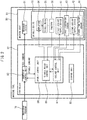
- FIG. 1 is a schematic sectional view of the spindle device of the present embodiment.
- the spindle device 10 includes a hollow housing 12 and a spindle 14 supported by the housing 12.
- the spindle 14 is formed in a cylindrical shape.
- the spindle 14 supports the tool 18 via a tool holder 19.
- the spindle 14 is rotatably supported via bearings 16a and 16b as front bearings and a bearing 17 as a rear bearing.
- the bearings 16a, 16b, and 17 of the present embodiment are rolling bearings.
- Each rolling bearing includes an inner ring, an outer ring, and rolling elements disposed between the inner ring and the outer ring.
- the inner rings of the bearings 16a, 16b, and 17 support the spindle 14.
- the spindle device 10 includes a bearing support part that secures the outer rings of the bearings 16a, 16b, and 17.
- the outer rings of the bearings 16a and 16b are secured to the inner surface of the housing 12.
- the portion of the housing 12, which is in contact with the bearings 16a and 16b, functions as a bearing support part.
- the spindle device 10 includes a rear housing 13 secured to the inner surface of the housing 12.
- the rear housing 13 supports the bearing 17.
- the outer ring of the bearing 17 is secured to the rear housing 13.
- the rear housing 13 functions as a bearing support part.
- the spindle device 10 includes a spindle motor 35 that rotates the spindle 14.
- the spindle motor 35 in the present embodiment is a built-in type motor.
- the spindle motor 35 includes a rotor 32 secured to the outer surface of the spindle 14 and a stator 34 secured to the inner surface of the housing 12.
- the spindle device 10 includes an amplifier 94 serving as an electric-supply device that supplies electricity to the spindle motor 35.
- a mechanism for holding and releasing the tool holder 19 is disposed inside the spindle 14.
- the spindle 14 holds the tool 18 via the tool holder 19.
- the tool 18 rotates with the spindle 14 by driving the spindle motor 35.
- the spindle device 10 includes an encoder 36 serving as a rotation angle detector for detecting the rotational speed of the spindle 14.
- the encoder 36 of the present embodiment includes a gear 36a and an encoder center 36b.
- the gear 36a of the present embodiment is disposed at the rear end part of the spindle 14.
- the encoder center 36b is secured to the rear housing 13 so as to face the gear 36a.
- the spindle device 10 of the present embodiment is formed so as to cool the bearings 16a, 16b, and 17 with a coolant. Cooling water or cooling oil can be used as the coolant.
- the housing 12 has first flow paths 21 and 23 through which a first coolant flows.
- the flow path 21 is formed so as to correspond to the positions of the bearings 16a and 16b.
- the flow path 21 is disposed on the side of the bearings 16a and 16b.
- the flow path 21 is formed in the vicinity of the bearings 16a and 16b.
- the flow path 21 of the present embodiment is formed so as to surround the bearings 16a and 16b.
- the rear housing 13 has a first flow path 23 through which the first coolant flows.
- the flow path 23 is formed so as to correspond to the position of the bearing 17.
- the flow path 23 is disposed on the side of the bearing 17.
- the flow path 23 is formed in the vicinity of the bearing 17.
- the flow path 23 of the present embodiment is formed so as to surround the bearing 17.
- first coolant of the present embodiment is formed so as to cool the spindle motor 35.
- a first flow path 22 through which the first coolant flows is formed between the housing 12 and a member that supports the stator 34.
- the spindle 14 includes second flow paths 25 and 26 through which a second coolant flows.
- the flow path 25 is formed so as to correspond to the positions of the bearings 16a and 16b.
- the flow path 25 is disposed on the side of the bearings 16a and 16b.
- the flow path 25 is formed in the vicinity of the bearings 16a and 16b.
- the flow path 26 is formed so as to correspond to the position of the bearing 17.
- the flow path 26 is disposed at the side of the bearing 17.
- the flow path 26 is formed in the vicinity of the bearing 17.
- the spindle device 10 includes a first coolant supply device 41 that supplies the first coolant to the bearing support part.
- the first coolant supply device 41 supplies the first coolant to the first flow paths 21, 22 and 23 formed in the housing 12 and the rear housing 13.
- the first coolant supply device 41 is formed so as to be able to adjust the temperature of the first coolant.
- the first coolant supply device 41 of the present embodiment includes a pump for supplying a coolant, a chiller unit for cooling the coolant, and a heater for heating the coolant.
- the chiller unit includes a compressor, an expansion valve, and a heat exchanger.
- a first temperature sensor 43 is disposed in the middle of a flow path returning from the first flow path 23 to the first coolant supply device 41. The first temperature sensor 43 detects the temperature of the coolant after the housing 12 and the rear housing 13 are cooled.
- the bearings 16a and 16b are cooled by the first coolant supplied to the first flow path 21.
- the bearing 17 is cooled by the first coolant supplied to the first flow path 23.
- the spindle motor 35 is cooled by the first coolant supplied to the first flow path 22.
- a coolant may be supplied from another coolant supply device to the first flow path 22 for cooling the spindle motor 35. That is, the device for cooling the spindle motor 35 may be formed separately from the device for cooling the bearings.
- the spindle device 10 includes a second coolant supply device 42 that supplies the second coolant to the spindle 14.
- the second coolant supply device 42 supplies the second coolant to the second flow paths 25 and 26 formed in the spindle 14.
- the second coolant supply device 42 is formed so as to adjust the temperature of the second coolant.
- the second coolant supply device 42 of the present embodiment includes a pump for supplying a coolant, and a chiller unit for cooling the coolant in the same way as first coolant supply device 41.
- a second temperature sensor 44 is disposed in the middle of a flow path returning from the second flow path 25 to the second coolant supply device 42. The second temperature sensor 44 detects the temperature of the coolant after the spindle 14 is cooled.
- the temperature sensors 43 and 44 of the present embodiment are formed so as to detect the temperature of the coolant after the spindle 14, the housing 12, and the rear housing 13 are cooled.
- the temperature sensors can be disposed at any positions where the temperature of the coolant can be detected.
- the temperature sensors may be arranged so as to detect the temperature of the coolant flowing out of the coolant supply devices 41 and 42.
- the temperature sensors may be arranged so as to detect the temperature of the coolant flowing through the respective flow paths 21, 22, 23, 25, and 26.
- FIG. 2 is a block diagram of the machine tool according to the present embodiment.
- the machine tool 80 includes a machine body 81 and a controller 82.
- the machine body 81 includes the spindle device 10 and a movement device 91 for moving the tool 18 relative to a workpiece.
- a movement device 91 for moving a tool in the X-axis direction and a device for moving the tool in the Y-axis direction.
- the movement device 91 includes a device for moving a table, to which the workpiece is secured, in the Z-axis direction.
- the movement device 91 is not limited to this embodiment, and any device that moves the tool relative to the workpiece can be adopted.
- the controller 82 is configured by, for example, a digital computer including a central processing unit (CPU), a random access memory (RAM), a read only memory (ROM), etc., which are connected to one another via a bus line.
- a machining program 78 in which a procedure for machining a workpiece is set, is input to the machine tool 80.
- the controller 82 controls the machine body 81 based on the machining program 78.
- the controller 82 includes a numerical control unit 83.
- the numerical control unit 83 transmits feed commands regarding the feed axes to the movement device 91 based on the machining program 78.
- the movement device 91 moves the tool 18 relative to the workpiece based on the feed commands.
- the controller 82 includes a spindle control unit 84 for controlling the spindle device 10.
- the numerical control unit 83 transmits a spindle command for controlling the spindle to the spindle control unit 84 based on the machining program 78.
- the rotational speed of the spindle motor 35 is set.
- the spindle command includes, for example, a command regarding to the rotational speed of the spindle motor 35 and a command regarding to the flow rate and temperature of the coolant.
- the spindle control unit 84 controls the spindle device 10 based on the spindle command.
- the spindle control unit 84 includes a spindle motor control unit 86 that controls the spindle motor 35.
- the spindle motor control unit 86 transmits an operation command for the spindle motor 35 to the amplifier 94 based on the spindle command.
- the operation command for the spindle motor 35 includes the rotational speed of the spindle motor 35.
- the amplifier 94 supplies electricity to the spindle motor 35 based on the operation command for the spindle motor.
- the spindle 14 is rotated by driving the spindle motor 35.
- the rotational speed of the spindle 14 is detected by an encoder 36.
- the output of the encoder 36 is transmitted to the spindle motor control unit 86.
- the spindle motor control unit 86 can correct the operation command for the spindle motor 35 based on the output of the encoder 36.
- the spindle control unit 84 includes a coolant control unit 87 that controls the coolant supply devices 41 and 42.
- the coolant control unit 87 transmits an operation command to the first coolant supply device 41 and the second coolant supply device 42. Further, the coolant control unit 87 acquires the temperature of the first coolant from the first temperature sensor 43. The coolant control unit 87 acquires the temperature of the second coolant from the second temperature sensor 44.
- the coolant control unit 87 acquires the rotational speed of the spindle motor 35 (rotational speed of the spindle 14) from the spindle motor control unit 86.
- the coolant control unit 87 controls the first coolant supply device 41 and the second coolant supply device 42 so that the temperature of the coolant varies so as to correspond to the rotational speed of the spindle motor 35. For example, when the temperature of the coolant acquired from the temperature sensors 43 and 44 is higher than a predetermined target temperature, the coolant control unit 87 controls the coolant supply devices 41 and 42 so as to reduce the temperature of the coolant.
- the controller 82 includes a storage unit 85 that stores information on the machine tool 80.
- the storage unit 85 stores the machining program 78, the target temperature of the coolant, and the target flow rate of the coolant.
- the storage unit 85 stores the target temperature of the first coolant and the target temperature of the second coolant, which correspond to the rotational speed of the spindle motor 35.
- the relationship between the rotational speed of the spindle motor 35 and the target temperature of the coolant is predetermined by a formula.
- the storage unit 85 stores this formula.
- the relationship between the rotational speed of the spindle motor 35 and the target temperature of the coolant may be predetermined in the correspondence table.
- the storage unit 85 may store this correspondence table.
- the bearing support part of the spindle device 10 of the present embodiment is formed of a material having a thermal expansion coefficient larger than that of the spindle 14.
- the thermal expansion coefficient of the housing 12 is larger than the thermal expansion coefficient of the spindle 14.
- the thermal expansion coefficient of the rear housing 13 is larger than the thermal expansion coefficient of the spindle 14.
- the spindle 14 is formed of carbon steel, and the housing 12 and the rear housing 13 are formed of an aluminum alloy.
- the material of the spindle 14 and the material of the bearing support part are not limited to this embodiment. Any materials, in which the thermal expansion coefficient of the bearing support part is larger than the thermal expansion coefficient of the spindle, can be adopted.
- CFRP carbon fiber reinforced plastic
- an aluminum alloy can be adopted as the material of the housing.
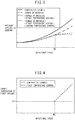
- FIG. 3 shows a graph of the relationship between the rotational speed of the spindle and the pressure applied to the bearings during operation.
- the pressure applied to the bearings 16a and 16b as front bearings is illustrated as an example, but the pressure applied to the bearing 17 as a rear bearing has a similar tendency.
- the spindle device 10 is assembled so that a predetermined pressure (preload) is applied to the rolling bearings. When the spindle device 10 is at rest, a pressure is applied to the rolling bearings.
- preload predetermined pressure
- FIG. 3 shows a graph of a spindle device of a comparative example in which the material of the spindle and the material of the bearing support part are the same.
- the spindle device of the comparative example for example, the spindle, the housing, and the rear housing are formed of carbon steel.
- the spindle device of the comparative example includes a first coolant supply device and a second coolant supply device.
- FIG. 4 shows a graph of the target temperature of the first coolant.
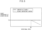
- FIG. 5 shows a graph of the target temperature of the second coolant.
- the horizontal axis indicates the rotational speed of the spindle motor 35, and the vertical axis indicates the target temperature of the coolant.
- the target temperature of the coolant in the graphs corresponds to the target temperature stored in the storage unit 85 of the controller 82.
- the first coolant supply device 41 is controlled so that the temperature of the first coolant remains constant regardless of the rotational speed.
- the second coolant supply device 42 is controlled so that the temperature of the second coolant remains constant regardless of the rotational speed.
- a constant temperature is referred to as a reference temperature Tr.
- Tr for example, the temperature of a room in which the machine tool is disposed, the temperature of the bed of the machine tool, etc. can be employed.
- the reference temperature Tr of the first coolant supply device 41 and the reference temperature Tr of the second coolant supply device 42 may have the same value or different values.
- the reference temperature of the first coolant supply device 41 is denoted by Tr1
- the reference temperature of the second coolant supply device 42 is denoted by Tr2.
- the temperature of the bearings increases due to the friction between the inner ring and the rolling elements of the bearing and the friction between the outer ring and the rolling elements.
- the temperature of the first coolant and the temperature of the second coolant are maintained constant.
- the flow paths 21, 23, 25, and 26 of the coolant are separated from the bearings 16a, 16b, and 17. This causes a difference between the temperature of the coolant and the temperature of the bearings 16a, 16b, and 17.
- the rotational speed of the spindle motor 35 increases, the temperature of the bearings 16a, 16b, and 17 increases.
- the spindle rotates at high speed.
- a high rotational speed 20,000 rpm or more can be illustrated, for example.
- the increase in pressure applied to the bearings is large in the high-speed range.
- FIG. 3 shows an embodiment of a spindle device in which the material is changed from the comparative example.
- the coolant control unit 87 performs a control so as to maintain the temperature of the first coolant and the temperature of the second coolant constant, in the same way as the spindle device of the comparative example.
- the thermal expansion coefficient of the housing 12 and the thermal expansion coefficient of the rear housing 13 are larger than the thermal expansion coefficient of the spindle 14. That is, the thermal expansion coefficient of the bearing support part is larger than the thermal expansion coefficient of the spindle.
- the expansion amount of the bearing support part is larger than the expansion amount of the spindle 14.
- the radial expansion amount of the bearing support part is larger than the radial expansion amount of the spindle 14.
- the pressure applied to the bearings in the spindle device of which the material is changed is smaller than the pressure applied to the bearings in the spindle device of the comparative example.
- the increase in the pressure applied to the bearings 16a, 16b, and 17 can be suppressed.
- the bearings 16a, 16b, and 17 can be prevented from being damaged, and the life of the bearings 16a, 16b, and 17 can be prevented from being shortened.
- the spindle device 10 of the present embodiment is suitable for an apparatus in which the bearings 16a, 16b, and 17 are secured to the housing 12 and the rear housing 13.
- a spring for adjusting the pressure applied to the front bearing may be disposed inside the spindle device.
- the pressure applied to the bearing is likely to increase with the operation of the spindle device.
- the effect of the present invention is remarkable.
- the temperature of the first coolant supplied to the housing 12 and the rear housing 13 can be adjusted by the first coolant supply device 41.
- the coolant control unit 87 can perform a first temperature control for changing the temperature of the coolant supplied to the first flow paths 21 to 23.
- the flow rate of the first coolant is controlled so as to be constant.
- the present invention is not limited to this embodiment, and the flow rate of the first coolant may be changed.
- the temperature of the coolant can be controlled so as to be the constant reference temperature Tr1 since the increase amount of the pressure received by the bearings is small.
- the coolant control unit 87 performs a control for maintaining the temperature of the first coolant constant, independently of the rotational speed, in the range where the rotational speed of the spindle motor 35 is Nt or less.
- the temperature of the first coolant is maintained at the reference temperature Tr1.
- the rotational speed Nt is predetermined.
- the rotational speed Nt can be set to, for example, a rotational speed at which the bearings 16a, 16b, and 17 is liable to be damaged.
- the coolant control unit 87 performs a control so that the temperature of the first coolant increases as the rotational speed of the spindle motor 35 increases. That is, the coolant control unit 87 can perform a control for enlarge the increase amount of temperature from the reference temperature Tr1 as the rotational speed of the spindle motor 35 increases.
- the first temperature control includes a control for increasing the temperature of the first coolant in accordance with the rotational speed of the spindle motor 35.
- the coolant control unit 87 of the spindle control unit 84 acquires the rotational speed of the spindle motor 35 (rotational speed of the spindle 14) from the spindle motor control unit 86.
- the coolant control unit 87 acquires the rotational speed of the operation command for the spindle motor 35 to be transmitted to the amplifier 94.
- the coolant control unit 87 may acquire the output value of the encoder 36.
- the coolant control unit 87 acquires the temperature of the first coolant from the first temperature sensor 43.
- the coolant control unit 87 adjusts the temperature of the first coolant so that the temperature of the first coolant approaches a target temperature based on the rotational speed.
- the coolant control unit 87 controls the first coolant supply device 41.
- the coolant control unit 87 can perform a control for reducing the cooling capacity of the first coolant supply device 41.
- the temperature of the first coolant may be increased by driving the heater.
- the temperature of the housing 12 and the rear housing 13 can be increased by the first temperature control, as the rotational speed of the spindle motor 35 increases.
- the expansion amount of the housing 12 and the rear housing 13 can be increased.
- FIG. 3 shows a graph of an example when the first temperature control is performed in the spindle device 10 of the present embodiment.
- a control is performed so as to maintain the temperature of the second coolant at the reference temperature Tr2 while changing the temperature of the first coolant.
- the expansion of the housing 12 and the rear housing 13 can be promoted. It can be seen that, with the first temperature control, the increase in the pressure applied to the bearings 16a, 16b, and 17 can be effectively suppressed in the range where the rotational speed is larger than Nt.
- the temperature of the second coolant supplied to the spindle 14 can be adjusted by the second coolant supply device 42.
- the coolant control unit 87 can perform a second temperature control for changing the temperature of the coolant supplied to the second flow paths 25 and 26.
- the flow rate of the second coolant is controlled so as to be constant.
- the present invention is not limited to this embodiment, and the flow rate of the second coolant may be changed.
- the coolant control unit 87 performs a control for maintaining the temperature of the second coolant constant, independently of the rotational speed, in the range where the rotational speed of the spindle motor 35 is Nt or less.
- the target temperature of the second coolant is maintained at the reference temperature Tr2.
- the coolant control unit 87 performs a control so that the temperature of the second coolant decreases as the rotational speed of the spindle motor 35 increases. That is, the coolant control unit 87 can perform a control for enlarging the decrease amount of temperature from the reference temperature Tr2 as the rotational speed of the spindle motor 35 increases.
- the second temperature control includes a control for reducing the temperature of the second coolant in accordance with the rotational speed of the spindle motor 35.
- the coolant control unit 87 acquires the temperature of the second coolant from the second temperature sensor 44.
- the coolant control unit 87 adjusts the temperature of the second coolant so that the temperature of the second coolant approaches the target temperature.
- the coolant control unit 87 controls the second coolant supply device 42. For example, in order to reduce the temperature of the second coolant, the coolant control unit 87 can perform a control for increasing the cooling capacity of the second coolant supply device 42.
- FIG. 3 shows a graph of an example when the first temperature control and the second temperature control are performed in the spindle device 10 of the present embodiment.
- the temperature of the first coolant is increased, and the temperature of the second coolant is decreased.
- the higher the rotational speed the larger the difference between the temperature of the first coolant and the temperature of the second coolant.
- the expansion of the housing 12 and the rear housing 13 can be promoted in the range where the rotational speed is larger than Nt.
- the expansion of the spindle 14 can be suppressed in the range where the rotational speed is larger than Nt. As a result, the increase in the pressure applied to the bearings 16a, 16b, and 17 can be effectively suppressed.
- the spindle device 10 includes the first coolant supply device 41 and the second coolant supply device 42.
- the spindle device can include at least one of the first coolant supply device and the second coolant supply device.
- the spindle device provided with the first coolant supply device can perform the first temperature control.
- the spindle device provided with the second coolant supply device can perform the second temperature control.
- the spindle device may not include the coolant supply device.
- the target temperature of the coolant is changed in the range where the rotational speed of the spindle motor 35 is larger than Nt.
- the target temperature of the coolant can be changed in the range of any rotational speed.
- the target temperature of the first coolant may be increased as the rotational speed increases in the range of all the rotational speeds.
- the target temperature of the second coolant may be reduced as the rotational speed increases in the range of all the rotational speeds.
- rolling bearing for supporting the spindle.
- the rolling bearing such as an angular bearing and a roller bearing can be adopted.
- the spindle device of the present embodiment holds a tool.
- the spindle device may hold a workpiece.
- a lathe can be illustrated, as an example, as a machine tool in which the spindle device holds a workpiece. In the lathe, the spindle device can hold and rotate a workpiece while the movement device can move a tool relative to the workpiece.
Landscapes
- Engineering & Computer Science (AREA)
- General Engineering & Computer Science (AREA)
- Mechanical Engineering (AREA)
- Auxiliary Devices For Machine Tools (AREA)
- Turning (AREA)
- Mounting Of Bearings Or Others (AREA)
- Support Of The Bearing (AREA)
- Rolling Contact Bearings (AREA)
Abstract
Description
- The present invention relates to a spindle device attached to a machine tool.
- A machine tool is provided with a spindle device that rotates a tool or a workpiece. For example, if the machine tool is provided with the spindle device that rotates the tool, the machine tool can rotate the tool about an axis. The machine tool can machine the workpiece into a desired shape by bringing the tool into contact with the workpiece and moving the tool relative to the workpiece. The spindle device includes a spindle to which a tool is connected. The spindle is supported by a housing via bearings. The rotation of the spindle causes the tool or workpiece to rotate.
- In machine tools, a tool or a workpiece may be rotated at high speed depending on the type of cutting. In a spindle device in which the spindle rotates at high speed, rolling bearings can be adopted as bearings for supporting the spindle.
- Japanese Laid-Open Patent Publication No.
2003-056582A - Patent literature 1: Japanese Laid-open Patent Publication No.
2003-056582A - In a spindle device provided with rolling bearings, a predetermined pressure is applied to each rolling bearing in the radial direction of the spindle. That is, the spindle device is assembled such that a preload is applied to each rolling bearing. Desired rolling bearing characteristics can be obtained by the preload applied to the rolling bearings. The range of magnitudes of a proper preload is predetermined.
- When the spindle device is driven so at to rotate the spindle, the temperature of the rolling bearing increases due to the friction between rolling elements and the inner ring of the rolling bearing and the friction between the rolling elements and the outer ring. Even if the spindle and the housing are made of the same material, they have different heat capacities because of their different volumes. The spindle having the volume which is smaller than that of the housing tends to increase in temperature due to its small heat capacity. On the other hand, the housing having the volume which is larger than that of the spindle is unlikely to increase in temperature due to its large heat capacity. Thus, the expansion amount of the spindle is larger than the expansion amount of the housing. In particular, the expansion amount of the spindle in the radial direction is larger than the expansion amount of the housing in the radial direction. Thus, when the spindle rotates, the pressure applied to the bearings increases. The higher the rotational speed of the spindle, the higher the temperature of the bearings. Thus, when the spindle rotates at high speed, the pressure acting on the bearings increases.
- In addition, since the inner ring of the bearing rotate with the spindle, a centrifugal force acts on the inner ring. Furthermore, the centrifugal force also acts on the rolling elements rotating around the inner ring. The centrifugal force acting on the inner ring and the rolling elements increases the pressure acting on the bearing. In particular, when the spindle rotates at high speed, the pressure acting on the bearing increases.
- Thus, when the pressure applied to the bearing is increased due to the rotation of the spindle, the life of the bearing may be shortened, or the bearing may be damaged. In particular, when the spindle rotates at high speed, the life of the bearing may be shortened or the bearing may be damaged.
- An object of the present invention is to provide a spindle device that suppresses a pressure applied to the rolling bearing during an operation period.
- A spindle device according to the present invention is attached to a machine tool and rotates a tool or a workpiece. The spindle device includes a spindle for supporting a tool or a workpiece, and a spindle motor for rotating the spindle. The spindle device includes a rolling bearing which has an inner ring, rolling elements, and an outer ring and supports the spindle with the inner ring, and a bearing support part that secures the outer ring of the rolling bearing. The bearing support part is formed of a material having a thermal expansion coefficient larger than that of the spindle.
- In the above-described invention, the spindle device can include a first coolant supply device that supplies a first coolant to the bearing support part. The bearing support part can have a first flow path through which the first coolant flows. The first flow path can be disposed on the side of the outer ring of the rolling bearing. The first coolant supply device can have a function of adjusting the temperature of the first coolant and supply the first coolant to the first flow path.
- In the above-described invention, the spindle device can include a controller that controls the first coolant supply device. The controller can implement a first temperature control for controlling the temperature of the first coolant. The first temperature control can include a control in which the temperature of the first coolant increases as the rotational speed of the spindle motor increases.
- In the above-described invention, the spindle device can include a second coolant supply device that supplies a second coolant to the spindle. The spindle can have a second flow path through which the second coolant flows. The second flow path can be disposed on the side of the inner ring of the rolling bearing. The second coolant supply device can have a function of adjusting the temperature of the second coolant and supply the second coolant to the second flow path.
- In the above-described invention, the spindle device can include a controller that controls the second coolant supply device. The controller can implement a second temperature control for controlling the temperature of the second coolant. The second temperature control can include a control in which the temperature of the second coolant decreases as the rotational speed of the spindle motor increases.
- According to the present invention, a spindle device that suppresses the pressure applied to the rolling bearing during an operation period can be provided.
-
-
FIG. 1 is a schematic sectional view of a spindle device according to an embodiment. -
FIG. 2 is a block diagram of a machine tool according to the embodiment. -
FIG. 3 is a graph showing the relationship between a rotational speed of a spindle motor and a pressure applied to rolling bearing in the embodiment. -
FIG. 4 is a graph showing the relationship between the rotational speed of the spindle motor and a target temperature of a first coolant in the embodiment. -
FIG. 5 is a graph showing the relationship between the rotational speed of the spindle motor and a target temperature of a second coolant in the embodiment. - The spindle device in an embodiment will be described with reference to
FIGS. 1 to 5 . The spindle device of the present embodiment is attached to a machine tool. The machine tool of the present embodiment is a numerically controlled machine tool that automatically performs a machining operation by relatively moving a tool and a workpiece based on a machining program. -
FIG. 1 is a schematic sectional view of the spindle device of the present embodiment. In the present embodiment, the direction in which thetool 18 is disposed is referred to as the front side of thespindle device 10, and the side opposite to the side in which thetool 18 is disposed is referred to as the rear side. Thespindle device 10 includes ahollow housing 12 and aspindle 14 supported by thehousing 12. Thespindle 14 is formed in a cylindrical shape. Thespindle 14 supports thetool 18 via atool holder 19. Thespindle 14 is rotatably supported viabearings bearing 17 as a rear bearing. Thebearings bearings spindle 14. - The
spindle device 10 includes a bearing support part that secures the outer rings of thebearings bearings housing 12. The portion of thehousing 12, which is in contact with thebearings spindle device 10 includes arear housing 13 secured to the inner surface of thehousing 12. Therear housing 13 supports thebearing 17. The outer ring of thebearing 17 is secured to therear housing 13. Therear housing 13 functions as a bearing support part. - The
spindle device 10 includes aspindle motor 35 that rotates thespindle 14. Thespindle motor 35 in the present embodiment is a built-in type motor. Thespindle motor 35 includes arotor 32 secured to the outer surface of thespindle 14 and astator 34 secured to the inner surface of thehousing 12. Thespindle device 10 includes anamplifier 94 serving as an electric-supply device that supplies electricity to thespindle motor 35. - Inside the
spindle 14, a mechanism for holding and releasing thetool holder 19 is disposed. During machining of a workpiece, thespindle 14 holds thetool 18 via thetool holder 19. Thetool 18 rotates with thespindle 14 by driving thespindle motor 35. - The
spindle device 10 includes anencoder 36 serving as a rotation angle detector for detecting the rotational speed of thespindle 14. Theencoder 36 of the present embodiment includes agear 36a and anencoder center 36b. Thegear 36a of the present embodiment is disposed at the rear end part of thespindle 14. Theencoder center 36b is secured to therear housing 13 so as to face thegear 36a. - The
spindle device 10 of the present embodiment is formed so as to cool thebearings - The
housing 12 hasfirst flow paths flow path 21 is formed so as to correspond to the positions of thebearings flow path 21 is disposed on the side of thebearings flow path 21 is formed in the vicinity of thebearings flow path 21 of the present embodiment is formed so as to surround thebearings rear housing 13 has afirst flow path 23 through which the first coolant flows. Theflow path 23 is formed so as to correspond to the position of thebearing 17. Theflow path 23 is disposed on the side of thebearing 17. Theflow path 23 is formed in the vicinity of thebearing 17. Theflow path 23 of the present embodiment is formed so as to surround thebearing 17. - Further, the first coolant of the present embodiment is formed so as to cool the
spindle motor 35. Afirst flow path 22 through which the first coolant flows is formed between thehousing 12 and a member that supports thestator 34. - The
spindle 14 includessecond flow paths flow path 25 is formed so as to correspond to the positions of thebearings flow path 25 is disposed on the side of thebearings flow path 25 is formed in the vicinity of thebearings flow path 26 is formed so as to correspond to the position of thebearing 17. Theflow path 26 is disposed at the side of thebearing 17. Theflow path 26 is formed in the vicinity of thebearing 17. - The
spindle device 10 includes a firstcoolant supply device 41 that supplies the first coolant to the bearing support part. The firstcoolant supply device 41 supplies the first coolant to thefirst flow paths housing 12 and therear housing 13. The firstcoolant supply device 41 is formed so as to be able to adjust the temperature of the first coolant. The firstcoolant supply device 41 of the present embodiment includes a pump for supplying a coolant, a chiller unit for cooling the coolant, and a heater for heating the coolant. The chiller unit includes a compressor, an expansion valve, and a heat exchanger. Afirst temperature sensor 43 is disposed in the middle of a flow path returning from thefirst flow path 23 to the firstcoolant supply device 41. Thefirst temperature sensor 43 detects the temperature of the coolant after thehousing 12 and therear housing 13 are cooled. - The
bearings first flow path 21. Thebearing 17 is cooled by the first coolant supplied to thefirst flow path 23. Further, thespindle motor 35 is cooled by the first coolant supplied to thefirst flow path 22. Note that a coolant may be supplied from another coolant supply device to thefirst flow path 22 for cooling thespindle motor 35. That is, the device for cooling thespindle motor 35 may be formed separately from the device for cooling the bearings. - The
spindle device 10 includes a secondcoolant supply device 42 that supplies the second coolant to thespindle 14. The secondcoolant supply device 42 supplies the second coolant to thesecond flow paths spindle 14. The secondcoolant supply device 42 is formed so as to adjust the temperature of the second coolant. The secondcoolant supply device 42 of the present embodiment includes a pump for supplying a coolant, and a chiller unit for cooling the coolant in the same way as firstcoolant supply device 41. Asecond temperature sensor 44 is disposed in the middle of a flow path returning from thesecond flow path 25 to the secondcoolant supply device 42. Thesecond temperature sensor 44 detects the temperature of the coolant after thespindle 14 is cooled. - The
temperature sensors spindle 14, thehousing 12, and therear housing 13 are cooled. However, the present invention is not limited to this embodiment. The temperature sensors can be disposed at any positions where the temperature of the coolant can be detected. For example, the temperature sensors may be arranged so as to detect the temperature of the coolant flowing out of thecoolant supply devices respective flow paths -
FIG. 2 is a block diagram of the machine tool according to the present embodiment. Referring toFIGS. 1 and2 , themachine tool 80 includes amachine body 81 and acontroller 82. Themachine body 81 includes thespindle device 10 and amovement device 91 for moving thetool 18 relative to a workpiece. In themachine body 81, for example, an X axis, a Y axis, and a Z axis, which are orthogonal to one another, are set as linear feed axes. Themovement device 91 includes a device for moving a tool in the X-axis direction and a device for moving the tool in the Y-axis direction. In addition, themovement device 91 includes a device for moving a table, to which the workpiece is secured, in the Z-axis direction. Themovement device 91 is not limited to this embodiment, and any device that moves the tool relative to the workpiece can be adopted. - The
controller 82 is configured by, for example, a digital computer including a central processing unit (CPU), a random access memory (RAM), a read only memory (ROM), etc., which are connected to one another via a bus line. Amachining program 78, in which a procedure for machining a workpiece is set, is input to themachine tool 80. Thecontroller 82 controls themachine body 81 based on themachining program 78. - The
controller 82 includes anumerical control unit 83. Thenumerical control unit 83 transmits feed commands regarding the feed axes to themovement device 91 based on themachining program 78. Themovement device 91 moves thetool 18 relative to the workpiece based on the feed commands. Thecontroller 82 includes aspindle control unit 84 for controlling thespindle device 10. Thenumerical control unit 83 transmits a spindle command for controlling the spindle to thespindle control unit 84 based on themachining program 78. In themachining program 78, the rotational speed of thespindle motor 35 is set. The spindle command includes, for example, a command regarding to the rotational speed of thespindle motor 35 and a command regarding to the flow rate and temperature of the coolant. - The
spindle control unit 84 controls thespindle device 10 based on the spindle command. Thespindle control unit 84 includes a spindlemotor control unit 86 that controls thespindle motor 35. The spindlemotor control unit 86 transmits an operation command for thespindle motor 35 to theamplifier 94 based on the spindle command. The operation command for thespindle motor 35 includes the rotational speed of thespindle motor 35. Theamplifier 94 supplies electricity to thespindle motor 35 based on the operation command for the spindle motor. Thespindle 14 is rotated by driving thespindle motor 35. The rotational speed of thespindle 14 is detected by anencoder 36. The output of theencoder 36 is transmitted to the spindlemotor control unit 86. The spindlemotor control unit 86 can correct the operation command for thespindle motor 35 based on the output of theencoder 36. - The
spindle control unit 84 includes acoolant control unit 87 that controls thecoolant supply devices coolant control unit 87 transmits an operation command to the firstcoolant supply device 41 and the secondcoolant supply device 42. Further, thecoolant control unit 87 acquires the temperature of the first coolant from thefirst temperature sensor 43. Thecoolant control unit 87 acquires the temperature of the second coolant from thesecond temperature sensor 44. - The
coolant control unit 87 acquires the rotational speed of the spindle motor 35 (rotational speed of the spindle 14) from the spindlemotor control unit 86. Thecoolant control unit 87 controls the firstcoolant supply device 41 and the secondcoolant supply device 42 so that the temperature of the coolant varies so as to correspond to the rotational speed of thespindle motor 35. For example, when the temperature of the coolant acquired from thetemperature sensors coolant control unit 87 controls thecoolant supply devices - The
controller 82 includes astorage unit 85 that stores information on themachine tool 80. For example, thestorage unit 85 stores themachining program 78, the target temperature of the coolant, and the target flow rate of the coolant. In particular, thestorage unit 85 stores the target temperature of the first coolant and the target temperature of the second coolant, which correspond to the rotational speed of thespindle motor 35. The relationship between the rotational speed of thespindle motor 35 and the target temperature of the coolant is predetermined by a formula. Thestorage unit 85 stores this formula. Alternatively, the relationship between the rotational speed of thespindle motor 35 and the target temperature of the coolant may be predetermined in the correspondence table. Thestorage unit 85 may store this correspondence table. - Referring to
FIG. 1 , the bearing support part of thespindle device 10 of the present embodiment is formed of a material having a thermal expansion coefficient larger than that of thespindle 14. In the present embodiment, the thermal expansion coefficient of thehousing 12 is larger than the thermal expansion coefficient of thespindle 14. Further, the thermal expansion coefficient of therear housing 13 is larger than the thermal expansion coefficient of thespindle 14. In the present embodiment, thespindle 14 is formed of carbon steel, and thehousing 12 and therear housing 13 are formed of an aluminum alloy. The material of thespindle 14 and the material of the bearing support part are not limited to this embodiment. Any materials, in which the thermal expansion coefficient of the bearing support part is larger than the thermal expansion coefficient of the spindle, can be adopted. For example, carbon fiber reinforced plastic (CFRP) can be adopted as the material of the spindle, and an aluminum alloy can be adopted as the material of the housing. -
FIG. 3 shows a graph of the relationship between the rotational speed of the spindle and the pressure applied to the bearings during operation. Here, the pressure applied to thebearings bearing 17 as a rear bearing has a similar tendency. Thespindle device 10 is assembled so that a predetermined pressure (preload) is applied to the rolling bearings. When thespindle device 10 is at rest, a pressure is applied to the rolling bearings. -
FIG. 3 shows a graph of a spindle device of a comparative example in which the material of the spindle and the material of the bearing support part are the same. In the spindle device of the comparative example, for example, the spindle, the housing, and the rear housing are formed of carbon steel. The spindle device of the comparative example includes a first coolant supply device and a second coolant supply device. -
FIG. 4 shows a graph of the target temperature of the first coolant.FIG. 5 shows a graph of the target temperature of the second coolant. In the graphs shown inFIGS. 4 and5 , the horizontal axis indicates the rotational speed of thespindle motor 35, and the vertical axis indicates the target temperature of the coolant. The target temperature of the coolant in the graphs corresponds to the target temperature stored in thestorage unit 85 of thecontroller 82. - Referring to
FIG. 4 , in the spindle device of the comparative example, the firstcoolant supply device 41 is controlled so that the temperature of the first coolant remains constant regardless of the rotational speed. Referring toFIG. 5 , in the spindle device of the comparative example, the secondcoolant supply device 42 is controlled so that the temperature of the second coolant remains constant regardless of the rotational speed. In the present embodiment, such a constant temperature is referred to as a reference temperature Tr. As the reference temperature Tr, for example, the temperature of a room in which the machine tool is disposed, the temperature of the bed of the machine tool, etc. can be employed. The reference temperature Tr of the firstcoolant supply device 41 and the reference temperature Tr of the secondcoolant supply device 42 may have the same value or different values. Hereinafter, the reference temperature of the firstcoolant supply device 41 is denoted by Tr1, and the reference temperature of the secondcoolant supply device 42 is denoted by Tr2. - When the spindle rotates, the temperature of the bearings increases due to the friction between the inner ring and the rolling elements of the bearing and the friction between the outer ring and the rolling elements. Referring to
FIG. 3 , in the spindle device of the comparative example, the temperature of the first coolant and the temperature of the second coolant are maintained constant. However, theflow paths bearings bearings spindle motor 35 increases, the temperature of thebearings spindle 14 rotates, a centrifugal force in a direction toward the outside acts on the inner rings of thebearings bearings spindle motor 35 increases. - Thus, as the rotational speed of the
spindle motor 35 increases, the temperature of thebearings spindle 14 increases, the centrifugal force increases. Thus, the pressure applied to thebearings spindle motor 35 increases. - In particular, in the
spindle device 10 of the present embodiment and the spindle device of the comparative example, the spindle rotates at high speed. As a high rotational speed, 20,000 rpm or more can be illustrated, for example. In the spindle device of the comparative example, the increase in pressure applied to the bearings is large in the high-speed range. -
FIG. 3 shows an embodiment of a spindle device in which the material is changed from the comparative example. In this spindle device, thecoolant control unit 87 performs a control so as to maintain the temperature of the first coolant and the temperature of the second coolant constant, in the same way as the spindle device of the comparative example. In thespindle device 10 of the present embodiment, the thermal expansion coefficient of thehousing 12 and the thermal expansion coefficient of therear housing 13 are larger than the thermal expansion coefficient of thespindle 14. That is, the thermal expansion coefficient of the bearing support part is larger than the thermal expansion coefficient of the spindle. When the temperature increases in the same amount, the expansion amount of the bearing support part is larger than the expansion amount of thespindle 14. - When the temperature of the
bearings spindle 14. Thus, it is possible to suppress the increase in the pressure applied to thebearings spindle 14 rotates at high speed, the increase in the pressure applied to thebearings bearings bearings - The
spindle device 10 of the present embodiment is suitable for an apparatus in which thebearings housing 12 and therear housing 13. For example, a spring for adjusting the pressure applied to the front bearing may be disposed inside the spindle device. In such a spindle device, when the temperature of the bearing increases, the increase in the pressure applied to the bearing can be suppressed by the spring. On the other hand, in the spindle device in which the bearing is secured to the bearing support part, the pressure applied to the bearing is likely to increase with the operation of the spindle device. Thus, the effect of the present invention is remarkable. - Referring to
FIGS. 1 and2 , in the present embodiment, the temperature of the first coolant supplied to thehousing 12 and therear housing 13 can be adjusted by the firstcoolant supply device 41. Thecoolant control unit 87 can perform a first temperature control for changing the temperature of the coolant supplied to thefirst flow paths 21 to 23. Note that, in the present embodiment, the flow rate of the first coolant is controlled so as to be constant. However, the present invention is not limited to this embodiment, and the flow rate of the first coolant may be changed. - In the range where the rotational speed of the
spindle motor 35 is low, the temperature of the coolant can be controlled so as to be the constant reference temperature Tr1 since the increase amount of the pressure received by the bearings is small. Referring toFIG. 4 , in the first temperature control, thecoolant control unit 87 performs a control for maintaining the temperature of the first coolant constant, independently of the rotational speed, in the range where the rotational speed of thespindle motor 35 is Nt or less. In this example, the temperature of the first coolant is maintained at the reference temperature Tr1. The rotational speed Nt is predetermined. The rotational speed Nt can be set to, for example, a rotational speed at which thebearings - In the range where the rotational speed of the
spindle motor 35 is larger than Nt, thecoolant control unit 87 performs a control so that the temperature of the first coolant increases as the rotational speed of thespindle motor 35 increases. That is, thecoolant control unit 87 can perform a control for enlarge the increase amount of temperature from the reference temperature Tr1 as the rotational speed of thespindle motor 35 increases. Thus, the first temperature control includes a control for increasing the temperature of the first coolant in accordance with the rotational speed of thespindle motor 35. - Referring to
FIGS. 1 ,2 , and4 , thecoolant control unit 87 of thespindle control unit 84 acquires the rotational speed of the spindle motor 35 (rotational speed of the spindle 14) from the spindlemotor control unit 86. Thecoolant control unit 87 acquires the rotational speed of the operation command for thespindle motor 35 to be transmitted to theamplifier 94. Alternatively, thecoolant control unit 87 may acquire the output value of theencoder 36. Thecoolant control unit 87 acquires the temperature of the first coolant from thefirst temperature sensor 43. - The
coolant control unit 87 adjusts the temperature of the first coolant so that the temperature of the first coolant approaches a target temperature based on the rotational speed. Thecoolant control unit 87 controls the firstcoolant supply device 41. For example, in order to increase the temperature of the first coolant, thecoolant control unit 87 can perform a control for reducing the cooling capacity of the firstcoolant supply device 41. Alternatively, the temperature of the first coolant may be increased by driving the heater. - In the range where the rotational speed is larger than Nt, the temperature of the
housing 12 and therear housing 13 can be increased by the first temperature control, as the rotational speed of thespindle motor 35 increases. The expansion amount of thehousing 12 and therear housing 13 can be increased. -
FIG. 3 shows a graph of an example when the first temperature control is performed in thespindle device 10 of the present embodiment. In this example, in the range where the rotational speed is greater than Nt, a control is performed so as to maintain the temperature of the second coolant at the reference temperature Tr2 while changing the temperature of the first coolant. In the range where the rotational speed is larger than Nt, the expansion of thehousing 12 and therear housing 13 can be promoted. It can be seen that, with the first temperature control, the increase in the pressure applied to thebearings - Referring to
FIGS. 1 and2 , in the present embodiment, the temperature of the second coolant supplied to thespindle 14 can be adjusted by the secondcoolant supply device 42. Thecoolant control unit 87 can perform a second temperature control for changing the temperature of the coolant supplied to thesecond flow paths - Referring to
FIG. 5 , in the second temperature control, thecoolant control unit 87 performs a control for maintaining the temperature of the second coolant constant, independently of the rotational speed, in the range where the rotational speed of thespindle motor 35 is Nt or less. In this example, the target temperature of the second coolant is maintained at the reference temperature Tr2. - In the range where the rotational speed of the
spindle motor 35 is larger than Nt, thecoolant control unit 87 performs a control so that the temperature of the second coolant decreases as the rotational speed of thespindle motor 35 increases. That is, thecoolant control unit 87 can perform a control for enlarging the decrease amount of temperature from the reference temperature Tr2 as the rotational speed of thespindle motor 35 increases. Thus, the second temperature control includes a control for reducing the temperature of the second coolant in accordance with the rotational speed of thespindle motor 35. - Referring to
FIGS. 1 ,2 , and5 , thecoolant control unit 87 acquires the temperature of the second coolant from thesecond temperature sensor 44. Thecoolant control unit 87 adjusts the temperature of the second coolant so that the temperature of the second coolant approaches the target temperature. Thecoolant control unit 87 controls the secondcoolant supply device 42. For example, in order to reduce the temperature of the second coolant, thecoolant control unit 87 can perform a control for increasing the cooling capacity of the secondcoolant supply device 42. -
FIG. 3 shows a graph of an example when the first temperature control and the second temperature control are performed in thespindle device 10 of the present embodiment. In this embodiment, in the range where the rotational speed is larger than Nt, the temperature of the first coolant is increased, and the temperature of the second coolant is decreased. The higher the rotational speed, the larger the difference between the temperature of the first coolant and the temperature of the second coolant. The expansion of thehousing 12 and therear housing 13 can be promoted in the range where the rotational speed is larger than Nt. Further, the expansion of thespindle 14 can be suppressed in the range where the rotational speed is larger than Nt. As a result, the increase in the pressure applied to thebearings - The
spindle device 10 according to the present embodiment includes the firstcoolant supply device 41 and the secondcoolant supply device 42. However, the present invention is not limited to this embodiment. The spindle device can include at least one of the first coolant supply device and the second coolant supply device. The spindle device provided with the first coolant supply device can perform the first temperature control. The spindle device provided with the second coolant supply device can perform the second temperature control. Alternatively, the spindle device may not include the coolant supply device. - In the first temperature control and the second temperature control described above, the target temperature of the coolant is changed in the range where the rotational speed of the
spindle motor 35 is larger than Nt. However, the present invention is not limited to this embodiment. The target temperature of the coolant can be changed in the range of any rotational speed. For example, in the first temperature control, the target temperature of the first coolant may be increased as the rotational speed increases in the range of all the rotational speeds. In the second temperature control, the target temperature of the second coolant may be reduced as the rotational speed increases in the range of all the rotational speeds. - Any type of rolling bearing can be adopted as the rolling bearing for supporting the spindle. For example, the rolling bearing such as an angular bearing and a roller bearing can be adopted.
- The spindle device of the present embodiment holds a tool. However, the present invention is not limited to this embodiment. The spindle device may hold a workpiece. A lathe can be illustrated, as an example, as a machine tool in which the spindle device holds a workpiece. In the lathe, the spindle device can hold and rotate a workpiece while the movement device can move a tool relative to the workpiece.
- The above embodiments can be combined as appropriate. In each figure described above, the same reference numerals are applied to the same or corresponding parts. The above embodiments are merely examples and does not limit the invention. Moreover, in the embodiments, the changes of the embodiment indicated in the claims are included.
-
- 10
- spindle device
- 12
- housing
- 13
- rear housing
- 14
- spindle
- 16a, 16b, 17
- bearing
- 18
- tool
- 21, 23, 25, 26
- flow path
- 35
- spindle motor
- 36
- encoder
- 41, 42
- coolant supply device
- 43, 44
- temperature sensor
- 82
- control device
- 86
- spindle motor control unit
- 87
- coolant control unit
Claims (5)
- A spindle device attached to a machine tool and rotates a tool or a workpiece, the spindle device comprising:a spindle for supporting the tool or the workpiece;a spindle motor for rotating the spindle;a rolling bearing having an inner ring, rolling elements, and an outer ring, the inner ring supporting the spindle; anda bearing support part for securing the outer ring of the rolling bearing, whereinthe bearing support part is formed of a material having a thermal expansion coefficient larger than that of the spindle.
- The spindle device according to claim 1, further comprising a first coolant supply device for supplying a first coolant to the bearing support part, wherein
the bearing support part has a first flow path through which the first coolant flows,
the first flow path is disposed on the side of the outer ring of the rolling bearing, and
the first coolant supply device has a function of adjusting the temperature of the first coolant and supplies the first coolant to the first flow path. - The spindle device according to claim 2, further comprising a controller for controlling the first coolant supply device, wherein
the controller performs a first temperature control for controlling the temperature of the first coolant, and
the first temperature control includes a control for increasing the temperature of the first coolant as the rotational speed of the spindle motor increases. - The spindle device according to claim 1, further comprising a second coolant supply device for supplying a second coolant to the spindle, wherein
the spindle has a second flow path through which the second coolant flows,
the second flow path is disposed on the side of the inner ring of the rolling bearing, and
the second coolant supply device has a function of adjusting the temperature of the second coolant and supplies the second coolant to the second flow path. - The spindle device according to claim 4, further comprising a controller for controlling the second coolant supply device, wherein
the controller performs a second temperature control for controlling the temperature of the second coolant, and
the second temperature control includes a control for reducing the temperature of the second coolant as the rotational speed of the spindle motor increases.
Applications Claiming Priority (1)
| Application Number | Priority Date | Filing Date | Title |
|---|---|---|---|
| PCT/JP2017/013401 WO2018179280A1 (en) | 2017-03-30 | 2017-03-30 | Main shaft device |
Publications (3)
| Publication Number | Publication Date |
|---|---|
| EP3604843A1 true EP3604843A1 (en) | 2020-02-05 |
| EP3604843A4 EP3604843A4 (en) | 2020-12-16 |
| EP3604843B1 EP3604843B1 (en) | 2022-02-09 |
Family
ID=63674426
Family Applications (1)
| Application Number | Title | Priority Date | Filing Date |
|---|---|---|---|
| EP17904011.8A Active EP3604843B1 (en) | 2017-03-30 | 2017-03-30 | Main shaft device |
Country Status (5)
| Country | Link |
|---|---|
| US (1) | US11148241B2 (en) |
| EP (1) | EP3604843B1 (en) |
| JP (1) | JP6997763B2 (en) |
| CN (1) | CN110325752A (en) |
| WO (1) | WO2018179280A1 (en) |
Families Citing this family (10)
| Publication number | Priority date | Publication date | Assignee | Title |
|---|---|---|---|---|
| JP6640394B1 (en) * | 2019-02-25 | 2020-02-05 | 株式会社日立パワーソリューションズ | Roller bearing cooling mechanism, bearing cooling method, and roll press device |
| JP7303029B2 (en) * | 2019-06-06 | 2023-07-04 | ファナック株式会社 | machine tools and systems |
| CN110285137B (en) * | 2019-07-10 | 2020-12-18 | 安徽晨光精工机电科技有限公司 | Rotary supporting structure for pressure vessel stirring device |
| JP7340445B2 (en) * | 2019-12-25 | 2023-09-07 | オークマ株式会社 | Spindle device |
| CN111473053B (en) * | 2020-06-08 | 2024-12-27 | 珠海格力电器股份有限公司 | Shaft assembly and transmission system |
| JP2022133043A (en) * | 2021-03-01 | 2022-09-13 | セイコーホールディングス株式会社 | Spindle cooling device and spindle cooling method |
| JP7187618B1 (en) * | 2021-07-06 | 2022-12-12 | 株式会社牧野フライス製作所 | Machine tool temperature controller |
| JP7701697B2 (en) * | 2021-08-19 | 2025-07-02 | 株式会社オータマ | Rotation transmission shaft unit, and motor and inverter test bench and EMC test equipment using the same |
| JP7790442B2 (en) * | 2021-10-26 | 2025-12-23 | 株式会社ジェイテクト | Spindle device |
| CN114939831B (en) * | 2022-07-26 | 2023-04-18 | 江苏京创先进电子科技有限公司 | Temperature control system and temperature control method for cooling water and cutting fluid |
Family Cites Families (29)
| Publication number | Priority date | Publication date | Assignee | Title |
|---|---|---|---|---|
| US2538229A (en) * | 1948-05-20 | 1951-01-16 | Timken Roiler Bearing Company | Bearing mounting |
| US2523983A (en) * | 1949-05-05 | 1950-09-26 | Bryant Grinder Corp | High-speed rotor mounting |
| US3947079A (en) * | 1974-11-11 | 1976-03-30 | Fag Bearings Corporation | Temperature compensated spindle |
| US4076191A (en) * | 1975-04-29 | 1978-02-28 | Rca Corporation | Spacecraft component rotation means |
| US4560289A (en) * | 1983-03-21 | 1985-12-24 | Cincinnati Milacron Inc. | Spindle mounting assembly with squeeze film damping |
| DE3722572A1 (en) * | 1987-07-08 | 1989-01-19 | Boehringer Werkzeugmaschinen | BEARING ARRANGEMENT FOR THE WORK SPINDLE OF A MACHINE TOOL |
| JPH0487704A (en) * | 1990-07-31 | 1992-03-19 | Nippondenso Co Ltd | Spindle device of machine tool |
| JP2971115B2 (en) * | 1990-10-01 | 1999-11-02 | 日本電産株式会社 | Spindle motor |
| JPH0610949A (en) * | 1992-06-22 | 1994-01-21 | Riken Corp | Bearing mechanism |
| JP2001162409A (en) * | 1999-12-14 | 2001-06-19 | Mori Seiki Co Ltd | Spindle unit |
| DE10027750C5 (en) * | 2000-06-03 | 2010-04-22 | Fischer Precise Deutschland Gmbh | Motor spindle for a machine tool and modular unit for such |
| JP2003056582A (en) * | 2001-08-13 | 2003-02-26 | Makino Milling Mach Co Ltd | Rotary axis device |
| US6913390B2 (en) * | 2001-08-13 | 2005-07-05 | Makino Milling Machine Company, Ltd | Rotating shaft apparatus |
| US8753016B2 (en) * | 2002-07-29 | 2014-06-17 | Nsk Ltd. | Rolling bearing, grease supply system, spindle unit, grease supply method, and grease supply program |
| EP1579951B1 (en) * | 2004-03-22 | 2008-03-19 | Paul Müller GmbH & Co. KG Unternehmensbeteiligungen | Machine tool spindle with a bearing provided with a capilar duct for conducting lubricant |
| JP2008041118A (en) * | 2006-08-01 | 2008-02-21 | Denso Corp | Storage device and in-vehicle navigation system |
| JP4264847B1 (en) * | 2008-07-17 | 2009-05-20 | 株式会社ニイガタマシンテクノ | Machine tool cooling system |
| US8303220B2 (en) * | 2009-04-22 | 2012-11-06 | Creare Incorporated | Device for axial delivery of cryogenic fluids through a machine spindle |
| JP2011167799A (en) * | 2010-02-18 | 2011-09-01 | Ntn Corp | Main spindle device |
| DE102010002804A1 (en) * | 2010-03-12 | 2011-09-15 | Index-Werke Gmbh & Co. Kg Hahn & Tessky | Multi-spindle lathe |
| CN102120266A (en) * | 2010-12-27 | 2011-07-13 | 东莞理工学院 | High-speed precise electric spindle cooling system |
| EP2818741A4 (en) * | 2012-02-23 | 2015-03-18 | Leizhen Zhang | Oil mist-free high-speed electric main shaft |
| CN102862092B (en) * | 2012-09-11 | 2015-07-29 | 浙江大学 | A kind of coolant jacket based on fractal runner and electro spindle |
| CN203830747U (en) * | 2014-05-27 | 2014-09-17 | 周贵英 | Efficient cooling spindle device |
| CN104108047B (en) * | 2014-07-18 | 2016-08-03 | 西安交通大学 | A kind of electro spindle shaft core cooling system |
| JP6691927B2 (en) * | 2015-02-12 | 2020-05-13 | フランツ ケスラー ゲーエムベーハー | Machine tools and machine tool units |
| CN104889424A (en) * | 2015-05-29 | 2015-09-09 | 上海大学 | Electric spindle with torque amplification function |
| KR20170082801A (en) * | 2016-01-07 | 2017-07-17 | (주)성림엔지니어링 | Pre-load change device for spindle bearing |
| DE102016119821A1 (en) * | 2016-10-18 | 2018-04-19 | Franz Kessler Gmbh | motor spindle |
-
2017
- 2017-03-30 US US16/498,702 patent/US11148241B2/en active Active
- 2017-03-30 CN CN201780086333.2A patent/CN110325752A/en active Pending
- 2017-03-30 WO PCT/JP2017/013401 patent/WO2018179280A1/en not_active Ceased
- 2017-03-30 JP JP2019508059A patent/JP6997763B2/en active Active
- 2017-03-30 EP EP17904011.8A patent/EP3604843B1/en active Active
Also Published As
| Publication number | Publication date |
|---|---|
| EP3604843B1 (en) | 2022-02-09 |
| US11148241B2 (en) | 2021-10-19 |
| WO2018179280A1 (en) | 2018-10-04 |
| CN110325752A (en) | 2019-10-11 |
| EP3604843A4 (en) | 2020-12-16 |
| JP6997763B2 (en) | 2022-01-18 |
| US20210101234A1 (en) | 2021-04-08 |
| JPWO2018179280A1 (en) | 2019-11-07 |
Similar Documents
| Publication | Publication Date | Title |
|---|---|---|
| EP3604843B1 (en) | Main shaft device | |
| EP1418352B1 (en) | Rotating shaft device | |
| JP5742534B2 (en) | Spindle device | |
| CN107848089B (en) | Rotary table for machine tool | |
| CN101164724A (en) | Spindle device | |
| EP3015201B1 (en) | Main spindle device for machine tool and machine tool | |
| EP3769911B1 (en) | Main spindle device of machine tool | |
| JPH0554565B2 (en) | ||
| JP2010023158A (en) | Cooling system for machine tool | |
| JP2000237902A (en) | Main shaft device | |
| JP6131139B2 (en) | Spindle device | |
| JP6076192B2 (en) | Rotating shaft device | |
| JP2003053632A (en) | Rotary axis device of machine tool | |
| US10160075B2 (en) | Main spindle device for machine tool and machine tool | |
| JP6728663B2 (en) | Machine Tools | |
| JP4679493B2 (en) | Machine tool spindle equipment | |
| JPS62152643A (en) | Highly accurate machining device | |
| JP2759232B2 (en) | Bearing device | |
| JPH09300173A (en) | Method and system of cooling main spindle of machine tool | |
| JP6610043B2 (en) | Machine tool with ball screw | |
| JP2003056582A (en) | Rotary axis device | |
| JP2000167739A (en) | Machine Tools | |
| JP2011033170A (en) | Fluid bearing device | |
| KR20180115492A (en) | Cooling device of main spindle for machine tools | |
| JP2009291916A (en) | Machine tool |
Legal Events
| Date | Code | Title | Description |
|---|---|---|---|
| STAA | Information on the status of an ep patent application or granted ep patent |
Free format text: STATUS: THE INTERNATIONAL PUBLICATION HAS BEEN MADE |
|
| PUAI | Public reference made under article 153(3) epc to a published international application that has entered the european phase |
Free format text: ORIGINAL CODE: 0009012 |
|
| STAA | Information on the status of an ep patent application or granted ep patent |
Free format text: STATUS: REQUEST FOR EXAMINATION WAS MADE |
|
| 17P | Request for examination filed |
Effective date: 20190927 |
|
| AK | Designated contracting states |
Kind code of ref document: A1 Designated state(s): AL AT BE BG CH CY CZ DE DK EE ES FI FR GB GR HR HU IE IS IT LI LT LU LV MC MK MT NL NO PL PT RO RS SE SI SK SM TR |
|
| AX | Request for extension of the european patent |
Extension state: BA ME |
|
| DAV | Request for validation of the european patent (deleted) | ||
| DAX | Request for extension of the european patent (deleted) | ||
| A4 | Supplementary search report drawn up and despatched |
Effective date: 20201113 |
|
| RIC1 | Information provided on ipc code assigned before grant |
Ipc: F16C 35/067 20060101AFI20201109BHEP Ipc: F16C 35/063 20060101ALI20201109BHEP Ipc: B23Q 11/12 20060101ALI20201109BHEP Ipc: B23Q 1/70 20060101ALI20201109BHEP Ipc: B23B 19/02 20060101ALI20201109BHEP Ipc: F16C 37/00 20060101ALI20201109BHEP Ipc: F16C 19/52 20060101ALI20201109BHEP Ipc: F16C 35/12 20060101ALI20201109BHEP Ipc: F16C 35/04 20060101ALI20201109BHEP |
|
| GRAP | Despatch of communication of intention to grant a patent |
Free format text: ORIGINAL CODE: EPIDOSNIGR1 |
|
| STAA | Information on the status of an ep patent application or granted ep patent |
Free format text: STATUS: GRANT OF PATENT IS INTENDED |
|
| INTG | Intention to grant announced |
Effective date: 20211022 |
|
| RIC1 | Information provided on ipc code assigned before grant |
Ipc: F16C 35/12 20060101ALI20211008BHEP Ipc: F16C 35/04 20060101ALI20211008BHEP Ipc: F16C 19/52 20060101ALI20211008BHEP Ipc: B23Q 11/12 20060101ALI20211008BHEP Ipc: B23Q 1/70 20060101ALI20211008BHEP Ipc: F16C 37/00 20060101ALI20211008BHEP Ipc: F16C 35/063 20060101ALI20211008BHEP Ipc: B23B 19/02 20060101ALI20211008BHEP Ipc: F16C 35/067 20060101AFI20211008BHEP |
|
| GRAS | Grant fee paid |
Free format text: ORIGINAL CODE: EPIDOSNIGR3 |
|
| GRAA | (expected) grant |
Free format text: ORIGINAL CODE: 0009210 |
|
| STAA | Information on the status of an ep patent application or granted ep patent |
Free format text: STATUS: THE PATENT HAS BEEN GRANTED |
|
| AK | Designated contracting states |
Kind code of ref document: B1 Designated state(s): AL AT BE BG CH CY CZ DE DK EE ES FI FR GB GR HR HU IE IS IT LI LT LU LV MC MK MT NL NO PL PT RO RS SE SI SK SM TR |
|
| REG | Reference to a national code |
Ref country code: GB Ref legal event code: FG4D |
|
| REG | Reference to a national code |
Ref country code: CH Ref legal event code: EP Ref country code: AT Ref legal event code: REF Ref document number: 1467690 Country of ref document: AT Kind code of ref document: T Effective date: 20220215 |
|
| REG | Reference to a national code |
Ref country code: DE Ref legal event code: R096 Ref document number: 602017053314 Country of ref document: DE |
|
| REG | Reference to a national code |
Ref country code: IE Ref legal event code: FG4D |
|
| REG | Reference to a national code |
Ref country code: LT Ref legal event code: MG9D |
|
| REG | Reference to a national code |
Ref country code: NL Ref legal event code: MP Effective date: 20220209 |
|
| REG | Reference to a national code |
Ref country code: AT Ref legal event code: MK05 Ref document number: 1467690 Country of ref document: AT Kind code of ref document: T Effective date: 20220209 |
|
| PG25 | Lapsed in a contracting state [announced via postgrant information from national office to epo] |
Ref country code: SE Free format text: LAPSE BECAUSE OF FAILURE TO SUBMIT A TRANSLATION OF THE DESCRIPTION OR TO PAY THE FEE WITHIN THE PRESCRIBED TIME-LIMIT Effective date: 20220209 Ref country code: RS Free format text: LAPSE BECAUSE OF FAILURE TO SUBMIT A TRANSLATION OF THE DESCRIPTION OR TO PAY THE FEE WITHIN THE PRESCRIBED TIME-LIMIT Effective date: 20220209 Ref country code: PT Free format text: LAPSE BECAUSE OF FAILURE TO SUBMIT A TRANSLATION OF THE DESCRIPTION OR TO PAY THE FEE WITHIN THE PRESCRIBED TIME-LIMIT Effective date: 20220609 Ref country code: NO Free format text: LAPSE BECAUSE OF FAILURE TO SUBMIT A TRANSLATION OF THE DESCRIPTION OR TO PAY THE FEE WITHIN THE PRESCRIBED TIME-LIMIT Effective date: 20220509 Ref country code: NL Free format text: LAPSE BECAUSE OF FAILURE TO SUBMIT A TRANSLATION OF THE DESCRIPTION OR TO PAY THE FEE WITHIN THE PRESCRIBED TIME-LIMIT Effective date: 20220209 Ref country code: LT Free format text: LAPSE BECAUSE OF FAILURE TO SUBMIT A TRANSLATION OF THE DESCRIPTION OR TO PAY THE FEE WITHIN THE PRESCRIBED TIME-LIMIT Effective date: 20220209 Ref country code: HR Free format text: LAPSE BECAUSE OF FAILURE TO SUBMIT A TRANSLATION OF THE DESCRIPTION OR TO PAY THE FEE WITHIN THE PRESCRIBED TIME-LIMIT Effective date: 20220209 Ref country code: ES Free format text: LAPSE BECAUSE OF FAILURE TO SUBMIT A TRANSLATION OF THE DESCRIPTION OR TO PAY THE FEE WITHIN THE PRESCRIBED TIME-LIMIT Effective date: 20220209 Ref country code: BG Free format text: LAPSE BECAUSE OF FAILURE TO SUBMIT A TRANSLATION OF THE DESCRIPTION OR TO PAY THE FEE WITHIN THE PRESCRIBED TIME-LIMIT Effective date: 20220509 |
|
| PG25 | Lapsed in a contracting state [announced via postgrant information from national office to epo] |
Ref country code: PL Free format text: LAPSE BECAUSE OF FAILURE TO SUBMIT A TRANSLATION OF THE DESCRIPTION OR TO PAY THE FEE WITHIN THE PRESCRIBED TIME-LIMIT Effective date: 20220209 Ref country code: LV Free format text: LAPSE BECAUSE OF FAILURE TO SUBMIT A TRANSLATION OF THE DESCRIPTION OR TO PAY THE FEE WITHIN THE PRESCRIBED TIME-LIMIT Effective date: 20220209 Ref country code: GR Free format text: LAPSE BECAUSE OF FAILURE TO SUBMIT A TRANSLATION OF THE DESCRIPTION OR TO PAY THE FEE WITHIN THE PRESCRIBED TIME-LIMIT Effective date: 20220510 Ref country code: FI Free format text: LAPSE BECAUSE OF FAILURE TO SUBMIT A TRANSLATION OF THE DESCRIPTION OR TO PAY THE FEE WITHIN THE PRESCRIBED TIME-LIMIT Effective date: 20220209 Ref country code: AT Free format text: LAPSE BECAUSE OF FAILURE TO SUBMIT A TRANSLATION OF THE DESCRIPTION OR TO PAY THE FEE WITHIN THE PRESCRIBED TIME-LIMIT Effective date: 20220209 |
|
| PG25 | Lapsed in a contracting state [announced via postgrant information from national office to epo] |
Ref country code: IS Free format text: LAPSE BECAUSE OF FAILURE TO SUBMIT A TRANSLATION OF THE DESCRIPTION OR TO PAY THE FEE WITHIN THE PRESCRIBED TIME-LIMIT Effective date: 20220609 |
|
| PG25 | Lapsed in a contracting state [announced via postgrant information from national office to epo] |
Ref country code: SM Free format text: LAPSE BECAUSE OF FAILURE TO SUBMIT A TRANSLATION OF THE DESCRIPTION OR TO PAY THE FEE WITHIN THE PRESCRIBED TIME-LIMIT Effective date: 20220209 Ref country code: SK Free format text: LAPSE BECAUSE OF FAILURE TO SUBMIT A TRANSLATION OF THE DESCRIPTION OR TO PAY THE FEE WITHIN THE PRESCRIBED TIME-LIMIT Effective date: 20220209 Ref country code: RO Free format text: LAPSE BECAUSE OF FAILURE TO SUBMIT A TRANSLATION OF THE DESCRIPTION OR TO PAY THE FEE WITHIN THE PRESCRIBED TIME-LIMIT Effective date: 20220209 Ref country code: EE Free format text: LAPSE BECAUSE OF FAILURE TO SUBMIT A TRANSLATION OF THE DESCRIPTION OR TO PAY THE FEE WITHIN THE PRESCRIBED TIME-LIMIT Effective date: 20220209 Ref country code: DK Free format text: LAPSE BECAUSE OF FAILURE TO SUBMIT A TRANSLATION OF THE DESCRIPTION OR TO PAY THE FEE WITHIN THE PRESCRIBED TIME-LIMIT Effective date: 20220209 Ref country code: CZ Free format text: LAPSE BECAUSE OF FAILURE TO SUBMIT A TRANSLATION OF THE DESCRIPTION OR TO PAY THE FEE WITHIN THE PRESCRIBED TIME-LIMIT Effective date: 20220209 |
|
| REG | Reference to a national code |
Ref country code: CH Ref legal event code: PL |
|
| REG | Reference to a national code |
Ref country code: DE Ref legal event code: R097 Ref document number: 602017053314 Country of ref document: DE |
|
| PG25 | Lapsed in a contracting state [announced via postgrant information from national office to epo] |
Ref country code: MC Free format text: LAPSE BECAUSE OF FAILURE TO SUBMIT A TRANSLATION OF THE DESCRIPTION OR TO PAY THE FEE WITHIN THE PRESCRIBED TIME-LIMIT Effective date: 20220209 Ref country code: AL Free format text: LAPSE BECAUSE OF FAILURE TO SUBMIT A TRANSLATION OF THE DESCRIPTION OR TO PAY THE FEE WITHIN THE PRESCRIBED TIME-LIMIT Effective date: 20220209 |
|
| REG | Reference to a national code |
Ref country code: BE Ref legal event code: MM Effective date: 20220331 |
|
| PLBE | No opposition filed within time limit |
Free format text: ORIGINAL CODE: 0009261 |
|
| STAA | Information on the status of an ep patent application or granted ep patent |
Free format text: STATUS: NO OPPOSITION FILED WITHIN TIME LIMIT |
|
| 26N | No opposition filed |
Effective date: 20221110 |
|
| PG25 | Lapsed in a contracting state [announced via postgrant information from national office to epo] |
Ref country code: LU Free format text: LAPSE BECAUSE OF NON-PAYMENT OF DUE FEES Effective date: 20220330 Ref country code: LI Free format text: LAPSE BECAUSE OF NON-PAYMENT OF DUE FEES Effective date: 20220331 Ref country code: IE Free format text: LAPSE BECAUSE OF NON-PAYMENT OF DUE FEES Effective date: 20220330 Ref country code: CH Free format text: LAPSE BECAUSE OF NON-PAYMENT OF DUE FEES Effective date: 20220331 |
|
| PG25 | Lapsed in a contracting state [announced via postgrant information from national office to epo] |
Ref country code: SI Free format text: LAPSE BECAUSE OF FAILURE TO SUBMIT A TRANSLATION OF THE DESCRIPTION OR TO PAY THE FEE WITHIN THE PRESCRIBED TIME-LIMIT Effective date: 20220209 Ref country code: BE Free format text: LAPSE BECAUSE OF NON-PAYMENT OF DUE FEES Effective date: 20220331 |
|
| PG25 | Lapsed in a contracting state [announced via postgrant information from national office to epo] |
Ref country code: MK Free format text: LAPSE BECAUSE OF FAILURE TO SUBMIT A TRANSLATION OF THE DESCRIPTION OR TO PAY THE FEE WITHIN THE PRESCRIBED TIME-LIMIT Effective date: 20220209 Ref country code: CY Free format text: LAPSE BECAUSE OF FAILURE TO SUBMIT A TRANSLATION OF THE DESCRIPTION OR TO PAY THE FEE WITHIN THE PRESCRIBED TIME-LIMIT Effective date: 20220209 |
|
| PG25 | Lapsed in a contracting state [announced via postgrant information from national office to epo] |
Ref country code: HU Free format text: LAPSE BECAUSE OF FAILURE TO SUBMIT A TRANSLATION OF THE DESCRIPTION OR TO PAY THE FEE WITHIN THE PRESCRIBED TIME-LIMIT; INVALID AB INITIO Effective date: 20170330 |
|
| PG25 | Lapsed in a contracting state [announced via postgrant information from national office to epo] |
Ref country code: TR Free format text: LAPSE BECAUSE OF FAILURE TO SUBMIT A TRANSLATION OF THE DESCRIPTION OR TO PAY THE FEE WITHIN THE PRESCRIBED TIME-LIMIT Effective date: 20220209 |
|
| PG25 | Lapsed in a contracting state [announced via postgrant information from national office to epo] |
Ref country code: MT Free format text: LAPSE BECAUSE OF FAILURE TO SUBMIT A TRANSLATION OF THE DESCRIPTION OR TO PAY THE FEE WITHIN THE PRESCRIBED TIME-LIMIT Effective date: 20220209 |
|
| PGFP | Annual fee paid to national office [announced via postgrant information from national office to epo] |
Ref country code: DE Payment date: 20250204 Year of fee payment: 9 |
|
| PGFP | Annual fee paid to national office [announced via postgrant information from national office to epo] |
Ref country code: FR Payment date: 20250210 Year of fee payment: 9 |
|
| PGFP | Annual fee paid to national office [announced via postgrant information from national office to epo] |
Ref country code: GB Payment date: 20250206 Year of fee payment: 9 Ref country code: IT Payment date: 20250211 Year of fee payment: 9 |