EP3604815A1 - Slide valve for compressor and screw compressor having same - Google Patents
Slide valve for compressor and screw compressor having same Download PDFInfo
- Publication number
- EP3604815A1 EP3604815A1 EP18770488.7A EP18770488A EP3604815A1 EP 3604815 A1 EP3604815 A1 EP 3604815A1 EP 18770488 A EP18770488 A EP 18770488A EP 3604815 A1 EP3604815 A1 EP 3604815A1
- Authority
- EP
- European Patent Office
- Prior art keywords
- slide valve
- compressor
- gas replenishing
- gas
- chamber
- Prior art date
- Legal status (The legal status is an assumption and is not a legal conclusion. Google has not performed a legal analysis and makes no representation as to the accuracy of the status listed.)
- Granted
Links
Images
Classifications
-
- F—MECHANICAL ENGINEERING; LIGHTING; HEATING; WEAPONS; BLASTING
- F04—POSITIVE - DISPLACEMENT MACHINES FOR LIQUIDS; PUMPS FOR LIQUIDS OR ELASTIC FLUIDS
- F04C—ROTARY-PISTON, OR OSCILLATING-PISTON, POSITIVE-DISPLACEMENT MACHINES FOR LIQUIDS; ROTARY-PISTON, OR OSCILLATING-PISTON, POSITIVE-DISPLACEMENT PUMPS
- F04C18/00—Rotary-piston pumps specially adapted for elastic fluids
- F04C18/08—Rotary-piston pumps specially adapted for elastic fluids of intermeshing-engagement type, i.e. with engagement of co-operating members similar to that of toothed gearing
- F04C18/12—Rotary-piston pumps specially adapted for elastic fluids of intermeshing-engagement type, i.e. with engagement of co-operating members similar to that of toothed gearing of other than internal-axis type
- F04C18/14—Rotary-piston pumps specially adapted for elastic fluids of intermeshing-engagement type, i.e. with engagement of co-operating members similar to that of toothed gearing of other than internal-axis type with toothed rotary pistons
- F04C18/16—Rotary-piston pumps specially adapted for elastic fluids of intermeshing-engagement type, i.e. with engagement of co-operating members similar to that of toothed gearing of other than internal-axis type with toothed rotary pistons with helical teeth, e.g. chevron-shaped, screw type
-
- F—MECHANICAL ENGINEERING; LIGHTING; HEATING; WEAPONS; BLASTING
- F04—POSITIVE - DISPLACEMENT MACHINES FOR LIQUIDS; PUMPS FOR LIQUIDS OR ELASTIC FLUIDS
- F04C—ROTARY-PISTON, OR OSCILLATING-PISTON, POSITIVE-DISPLACEMENT MACHINES FOR LIQUIDS; ROTARY-PISTON, OR OSCILLATING-PISTON, POSITIVE-DISPLACEMENT PUMPS
- F04C28/00—Control of, monitoring of, or safety arrangements for, pumps or pumping installations specially adapted for elastic fluids
- F04C28/10—Control of, monitoring of, or safety arrangements for, pumps or pumping installations specially adapted for elastic fluids characterised by changing the positions of the inlet or outlet openings with respect to the working chamber
- F04C28/12—Control of, monitoring of, or safety arrangements for, pumps or pumping installations specially adapted for elastic fluids characterised by changing the positions of the inlet or outlet openings with respect to the working chamber using sliding valves
-
- F—MECHANICAL ENGINEERING; LIGHTING; HEATING; WEAPONS; BLASTING
- F04—POSITIVE - DISPLACEMENT MACHINES FOR LIQUIDS; PUMPS FOR LIQUIDS OR ELASTIC FLUIDS
- F04C—ROTARY-PISTON, OR OSCILLATING-PISTON, POSITIVE-DISPLACEMENT MACHINES FOR LIQUIDS; ROTARY-PISTON, OR OSCILLATING-PISTON, POSITIVE-DISPLACEMENT PUMPS
- F04C29/00—Component parts, details or accessories of pumps or pumping installations, not provided for in groups F04C18/00 - F04C28/00
- F04C29/06—Silencing
-
- F—MECHANICAL ENGINEERING; LIGHTING; HEATING; WEAPONS; BLASTING
- F04—POSITIVE - DISPLACEMENT MACHINES FOR LIQUIDS; PUMPS FOR LIQUIDS OR ELASTIC FLUIDS
- F04C—ROTARY-PISTON, OR OSCILLATING-PISTON, POSITIVE-DISPLACEMENT MACHINES FOR LIQUIDS; ROTARY-PISTON, OR OSCILLATING-PISTON, POSITIVE-DISPLACEMENT PUMPS
- F04C29/00—Component parts, details or accessories of pumps or pumping installations, not provided for in groups F04C18/00 - F04C28/00
- F04C29/06—Silencing
- F04C29/065—Noise dampening volumes, e.g. muffler chambers
-
- F—MECHANICAL ENGINEERING; LIGHTING; HEATING; WEAPONS; BLASTING
- F04—POSITIVE - DISPLACEMENT MACHINES FOR LIQUIDS; PUMPS FOR LIQUIDS OR ELASTIC FLUIDS
- F04C—ROTARY-PISTON, OR OSCILLATING-PISTON, POSITIVE-DISPLACEMENT MACHINES FOR LIQUIDS; ROTARY-PISTON, OR OSCILLATING-PISTON, POSITIVE-DISPLACEMENT PUMPS
- F04C2270/00—Control; Monitoring or safety arrangements
- F04C2270/12—Vibration
- F04C2270/125—Controlled or regulated
-
- F—MECHANICAL ENGINEERING; LIGHTING; HEATING; WEAPONS; BLASTING
- F04—POSITIVE - DISPLACEMENT MACHINES FOR LIQUIDS; PUMPS FOR LIQUIDS OR ELASTIC FLUIDS
- F04C—ROTARY-PISTON, OR OSCILLATING-PISTON, POSITIVE-DISPLACEMENT MACHINES FOR LIQUIDS; ROTARY-PISTON, OR OSCILLATING-PISTON, POSITIVE-DISPLACEMENT PUMPS
- F04C2270/00—Control; Monitoring or safety arrangements
- F04C2270/13—Noise
- F04C2270/135—Controlled or regulated
-
- F—MECHANICAL ENGINEERING; LIGHTING; HEATING; WEAPONS; BLASTING
- F04—POSITIVE - DISPLACEMENT MACHINES FOR LIQUIDS; PUMPS FOR LIQUIDS OR ELASTIC FLUIDS
- F04C—ROTARY-PISTON, OR OSCILLATING-PISTON, POSITIVE-DISPLACEMENT MACHINES FOR LIQUIDS; ROTARY-PISTON, OR OSCILLATING-PISTON, POSITIVE-DISPLACEMENT PUMPS
- F04C2270/00—Control; Monitoring or safety arrangements
- F04C2270/14—Pulsations
- F04C2270/145—Controlled or regulated
Definitions
- Some embodiments of the present disclosure relate to a field of air conditioning devices, and in particular to a slide valve for a compressor and a screw compressor with the slide valve.
- a great refrigerating capacity may be required in some situations in a market, however a size of a former refrigerating unit may not be changed.
- an economizer needs to be added to the refrigerating unit, to mix high-pressure gases and lead mixed gas to a compression chamber of a compressor after achieving a required pressure. In this way, an objective of increasing the refrigerating capacity may be achieved.
- an axial gas replenishing process is as follows: a gas channel is processed on a compressor body; when a gas replenishing structure switches on to replenish the gas, air may enter into a gas replenishing hole which is reserved on the compressor body through a gas replenishing port disposed on an outer surface of the compressor body; then the gas may enter into a gas replenishing hole of an exhaust bearing base of the compressor and enter into a rotor compression chamber subsequently after rotation, to complete the gas replenishing process.
- a diameter ⁇ of the gas replenishing hole in the conventional art is 20 mm.
- Some embodiments of the present disclosure provide a slide valve for a compressor capable of reducing noise and a screw compressor with the slide valve.
- An embodiment of the present disclosure provides a slide valve for a compressor, including a slide valve main body, a gas replenishing chamber and a gas replenishing outlet hole, wherein the gas replenishing chamber is disposed in the slide valve main body, the gas replenishing outlet hole is provided on a surface, facing to a compression chamber of the compressor, of the slide valve main body, and the gas replenishing outlet hole is in communication with the gas replenishing chamber.
- the slide valve main body includes a top central line, two sides of the top central line is provided with at least one group of gas replenishing outlet hole group respectively, and the at least one group of gas replenishing outlet hole group includes at least one gas replenishing outlet hole.
- an end of the slide valve main body is provided with an opening which is in communication with the gas replenishing chamber
- the slide valve for the compressor further includes a sealing and pressing plate, the sealing and pressing plate is fixedly provided on the slide valve main body, and seals the opening.
- the slide valve includes a gas replenishing inlet hole provided on a side of the slide valve main body, wherein the gas replenishing inlet hole is in communication with the gas replenishing chamber.
- the gas replenishing chamber includes a round cross section, and a diameter of the gas replenishing chamber is 45mm-55mm.
- the gas replenishing outlet hole includes a round cross section, and a diameter of the gas replenishing outlet hole is 4mm-6mm.
- Some embodiments of the present disclosure provide a screw compressor, including a compressor body, a screw disposed in a rotor chamber of the compressor body and a slide valve disposed inside the compressor body.
- the slide valve is the abovementioned slide valve for the compressor, and a side, provided with a gas replenishing outlet hole, of the slide valve faces to the rotor chamber of the compressor body.
- a top central line of the slide valve corresponds to a connecting line of points of intersection of inner circles of the two screws.
- the screw compressor further includes a gas replenishing pipe, the gas replenishing pipe passes through the compressor body, and is coupled to the slide valve and in communication with the gas replenishing chamber of the slide valve.
- the slide valve main body is provided with the gas replenishing chamber therein, the surface, facing to the compression chamber, of the slide valve main body is provided with the gas replenishing outlet hole, to buffer the air.
- gas replenishing outlet hole to buffer the air.
- a slide valve for a compressor includes a slide valve main body 10.
- the slide valve main body 10 is provided with a gas replenishing chamber 11 therein.
- a surface, facing to a compression chamber of the compressor, of the slide valve main body 10 is provided with a gas replenishing outlet hole 12, and the gas replenishing outlet hole 12 is in communication with the gas replenishing chamber 11.
- the slide valve main body 10 is provided with the gas replenishing chamber 11 therein, by which air is buffered to some extent, and gas pulsation is reduced. Accordingly, noise of the compressor caused due to air impact during replenishing gas is reduced, the noise when the compressor works is reduced, and comfort is improved during using.
- the slide valve main body 10 includes a top central line 13.
- points on the top central line 13 correspond to points of intersection of inner circles of two screws 31 one to one.
- a side, facing to the compression chamber, of the slide valve main body 10 is a curve surface including an arc surface on two sides of the top central line 13.
- two sides of the top central line 13 are provided with at least one group of gas replenishing outlet hole group (each arc surface is provided with at least one group of gas replenishing outlet hole group), respectively.
- the at least one group of gas replenishing outlet hole group includes at least one gas replenishing outlet hole 12.
- Two sides of the top central line 13 are provided with the at least one group of gas replenishing outlet hole group, thereby ensuring an enough gas replenishing quantity.
- a specific quantity of the gas replenishing outlet hole groups is determined in accordance with the need, for example, more gas replenishing outlet hole groups may be configured when the required gas replenishing quantity is great.
- a quantity of the gas replenishing outlet holes 12 inside each gas replenishing outlet hole group may be determined in accordance with the required gas replenishing quantity as well. For example, eleven gas replenishing outlet holes 12 is disposed on the slide valve main body 10.
- a plurality of gas replenishing outlet holes 12 in one gas replenishing outlet hole group is provided along a helix line of the screw of the screw compressor, as to ensure that each of the plurality of gas replenishing outlet holes 12 corresponds to a groove between two teeth of the screw 31. Accordingly, a gas replenishing effect is ensured.
- the gas replenishing outlet hole 12 may be the hole disposed on the slide valve main body 10, or the slide valve main body 10 may be fixedly connected with an air duct thereon, and a gas outlet of the air duct may be taken as the gas replenishing outlet hole 12.
- the gas replenishing chamber 11 has a round cross section, a range of a diameter of the gas replenishing chamber 11 is 45 mm-55 mm. In an exemplary embodiment, the diameter of the gas replenishing chamber 11 is 49 mm. In this way, the gas replenishing quantity is ensured, and an effect of buffering and reducing noise is ensured. Furthermore, a structural strength of the slide valve main body 10 is ensured. Of course, the diameter of the gas replenishing chamber 11 may be 45mm, 48mm, 50mm, 52mm, 55mm and so on.
- the gas replenishing outlet hole 12 has a round cross section, and a diameter of the gas replenishing outlet hole 12 is 4mm-16mm. In an exemplary embodiment, the diameter of the gas replenishing outlet hole 12 is 5mm.
- the slide valve for the compressor may further include a sealing and pressing plate 14.
- the sealing and pressing plate 14 is fixedly coupled to the slide valve main body 10, and seals the opening. By the configured sealing and pressing plate 14, air tightness of the gas replenishing chamber 11 is ensured, and air leakage is prevented. Accordingly, the gas replenishing effect is ensured.
- the sealing and pressing plate 14 may be fixedly connected to the slide valve main body 10 by fixation with a bolt, welding, riveting and other methods.
- the side of the slide valve main body 10 is provided with a gas replenishing inlet hole 15 which is in communication with the gas replenishing chamber 11.
- gas replenishing inlet hole 15 gas is led into the gas replenishing chamber 11 of the slide valve main body 10, so as to replenish for the compressor.
- a screw compressor including a compressor body 30, a screw 31 disposed in a rotor chamber of the compressor body 30 and a slide valve disposed inside the compressor body 30.
- the slide valve is the abovementioned slide valve for the compressor.
- a side, provided with a gas replenishing outlet hole 12, of the slide valve faces to the rotor chamber of the compressor body 30.
- the screw compressor is provided with the slide valve therein, in this way gas pulsation may be reduced when the compressor replenishes gas. Accordingly, noise caused due to replenishment of the gas may be reduced.
- a top central line 13 of the slide valve corresponds to a connecting line of points of intersection of inner circles of the two screws 31. In this way, a gas replenishing effect of the gas replenishing outlet hole 12 on the slide valve main body 10 may be ensured.
- the screw compressor may further include a gas replenishing pipe 32.
- the gas replenishing pipe 32 passes through the compressor body 30, and is connected to the slide valve and in communication with the gas replenishing chamber 11 of the slide valve. By the gas replenishing pipe 32, the gas may be led into a gas replenishing chamber 11 of the slide valve main body 10.
- a gas replenishing inlet hole 15 of the slide valve is in communication with a gas replenishing port of the compressor body 30.
- the diameter is ⁇ 5 mm.
- one gas replenishing chamber 11 is disposed inside the slide valve main body 10.
- the gas replenishing chamber 11 is a hollow chamber with a diameter ⁇ of 49mm and a length of 65mm.
- An arc surface on which the slide valve main body 10 is in contact with a rotor (the screw 31) is provided with the gas replenishing outlet holes 12.
- a calculated gas replenishing area is equivalent to one gas replenishing hole with a diameter ⁇ of 16.58mm.
- the gas may enter into a rotor compression chamber by the gas replenishing outlet hole 12 on the arc surface, as to complete a gas replenishing process.
- the gas replenishing outlet hole 12 having the small diameter, it is conducive to reducing gas pulsation, as to accordingly reduce noise caused during replenishing the gas.
- the diameter ⁇ of the gas replenishing outlet hole 12 is 5mm, when a rotor (the screw 31) tooth passes the gas replenishing outlet hole 12, leakage of the gas on two sides of the tooth is improved well, with the better gas replenishing effect.
- the slide valve for the compressor and the screw compressor with the slide valve has the following technical effects.
- the gas replenishing chamber is processed inside the slide valve main body, a bottom is sealed with the sealing and pressing plate.
- the gas may have certain buffering effect in the gas replenishing chamber and reduce the gas pulsation.
- the gas may enter into the rotor (screw) compression chamber by the gas replenishing outlet hole of the arc surface of the slide valve main body, in this way the gas replenishing process may be completed.
- the gas pulsation caused by replenishment of the gas may be reduced, and it is conducive to reduce the noise of the compressor during replenishing the gas; furthermore, the problem that the gas is leaked when a top of the rotor (screw) tooth of the compressor passes the gas replenishing outlet hole may be improved as well.
Landscapes
- Engineering & Computer Science (AREA)
- Mechanical Engineering (AREA)
- General Engineering & Computer Science (AREA)
- Applications Or Details Of Rotary Compressors (AREA)
- Details Of Valves (AREA)
Abstract
Description
- Some embodiments of the present disclosure relate to a field of air conditioning devices, and in particular to a slide valve for a compressor and a screw compressor with the slide valve.
- A great refrigerating capacity may be required in some situations in a market, however a size of a former refrigerating unit may not be changed. In order to meet the market demand, an economizer needs to be added to the refrigerating unit, to mix high-pressure gases and lead mixed gas to a compression chamber of a compressor after achieving a required pressure. In this way, an objective of increasing the refrigerating capacity may be achieved.
- For a related screw compressor, most of the screw compressors may take an axial gas replenishing mode, and an axial gas replenishing process is as follows: a gas channel is processed on a compressor body; when a gas replenishing structure switches on to replenish the gas, air may enter into a gas replenishing hole which is reserved on the compressor body through a gas replenishing port disposed on an outer surface of the compressor body; then the gas may enter into a gas replenishing hole of an exhaust bearing base of the compressor and enter into a rotor compression chamber subsequently after rotation, to complete the gas replenishing process. A diameter Φ of the gas replenishing hole in the conventional art is 20 mm. There are problems that the air may have great pulsation in a gas replenishing channel, a great extra exciting force may be generated, and noise of the compressor may be increased.
- Some embodiments of the present disclosure provide a slide valve for a compressor capable of reducing noise and a screw compressor with the slide valve.
- An embodiment of the present disclosure provides a slide valve for a compressor, including a slide valve main body, a gas replenishing chamber and a gas replenishing outlet hole, wherein the gas replenishing chamber is disposed in the slide valve main body, the gas replenishing outlet hole is provided on a surface, facing to a compression chamber of the compressor, of the slide valve main body, and the gas replenishing outlet hole is in communication with the gas replenishing chamber.
- In an exemplary embodiment, the slide valve main body includes a top central line, two sides of the top central line is provided with at least one group of gas replenishing outlet hole group respectively, and the at least one group of gas replenishing outlet hole group includes at least one gas replenishing outlet hole.
- In an exemplary embodiment, along an extension direction of the top central line, an end of the slide valve main body is provided with an opening which is in communication with the gas replenishing chamber, the slide valve for the compressor further includes a sealing and pressing plate, the sealing and pressing plate is fixedly provided on the slide valve main body, and seals the opening.
- In an exemplary embodiment, the slide valve includes a gas replenishing inlet hole provided on a side of the slide valve main body, wherein the gas replenishing inlet hole is in communication with the gas replenishing chamber.
- In an exemplary embodiment, the gas replenishing chamber includes a round cross section, and a diameter of the gas replenishing chamber is 45mm-55mm.
- In an exemplary embodiment, the gas replenishing outlet hole includes a round cross section, and a diameter of the gas replenishing outlet hole is 4mm-6mm.
- Some embodiments of the present disclosure provide a screw compressor, including a compressor body, a screw disposed in a rotor chamber of the compressor body and a slide valve disposed inside the compressor body. The slide valve is the abovementioned slide valve for the compressor, and a side, provided with a gas replenishing outlet hole, of the slide valve faces to the rotor chamber of the compressor body.
- In an exemplary embodiment, there are two screws meshed with each other, and a top central line of the slide valve corresponds to a connecting line of points of intersection of inner circles of the two screws.
- In an exemplary embodiment, the screw compressor further includes a gas replenishing pipe, the gas replenishing pipe passes through the compressor body, and is coupled to the slide valve and in communication with the gas replenishing chamber of the slide valve.
- In accordance with the slide valve for the compressor and the screw compressor with the same in some embodiments of the present disclosure, the slide valve main body is provided with the gas replenishing chamber therein, the surface, facing to the compression chamber, of the slide valve main body is provided with the gas replenishing outlet hole, to buffer the air. In this way, when the compressor replenishes the gas, gas pulsation may be effectively reduced. Accordingly, vibration and noise of the compressor may be reduced.
- The accompanying drawings described herein are used to provide a further understanding of the present disclosure, and constitute a part of the present application, and the exemplary embodiments of the present disclosure and the description thereof are used to explain the present disclosure, but do not constitute improper limitations to the present disclosure. In the drawings:
-
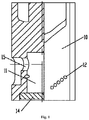
Fig. 1 is a structure diagram of a slide valve for a compressor according to an embodiment of the present disclosure. -
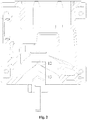
Fig. 2 is a transverse cross-section structure diagram of a screw compressor according to an embodiment of the present disclosure. -
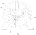
Fig. 3 is a longitudinal cross-section structure diagram of a screw compressor according to an embodiment of the present disclosure. - 10. Slide valve main body; 11. gas replenishing chamber; 12. gas replenishing outlet hole; 13. top central line; 14. sealing and pressing plate; 15. gas replenishing inlet hole; 30. compressor body; 31. screw; 32. gas replenishing pipe.
- The present disclosure will be described in detail below by using drawings for reference and in combination with the embodiments.
- As shown in
Fig. 1 ,Fig. 2 andFig. 3 , according to an embodiment of the present disclosure, a slide valve for a compressor includes a slide valvemain body 10. The slide valvemain body 10 is provided with agas replenishing chamber 11 therein. A surface, facing to a compression chamber of the compressor, of the slide valvemain body 10 is provided with a gas replenishingoutlet hole 12, and the gas replenishingoutlet hole 12 is in communication with thegas replenishing chamber 11. The slide valvemain body 10 is provided with thegas replenishing chamber 11 therein, by which air is buffered to some extent, and gas pulsation is reduced. Accordingly, noise of the compressor caused due to air impact during replenishing gas is reduced, the noise when the compressor works is reduced, and comfort is improved during using. - By referring to
Fig. 1 ,Fig. 2 andFig. 3 , the slide valvemain body 10 includes a topcentral line 13. When the slide valvemain body 10 is installed on a dual-screw compressor, points on the topcentral line 13 correspond to points of intersection of inner circles of twoscrews 31 one to one. A side, facing to the compression chamber, of the slide valvemain body 10 is a curve surface including an arc surface on two sides of the topcentral line 13. - In an exemplary embodiment, two sides of the top
central line 13 are provided with at least one group of gas replenishing outlet hole group (each arc surface is provided with at least one group of gas replenishing outlet hole group), respectively. The at least one group of gas replenishing outlet hole group includes at least one gas replenishingoutlet hole 12. Two sides of the topcentral line 13 are provided with the at least one group of gas replenishing outlet hole group, thereby ensuring an enough gas replenishing quantity. A specific quantity of the gas replenishing outlet hole groups is determined in accordance with the need, for example, more gas replenishing outlet hole groups may be configured when the required gas replenishing quantity is great. A quantity of the gas replenishingoutlet holes 12 inside each gas replenishing outlet hole group may be determined in accordance with the required gas replenishing quantity as well. For example, eleven gas replenishingoutlet holes 12 is disposed on the slide valvemain body 10. - A plurality of gas replenishing
outlet holes 12 in one gas replenishing outlet hole group is provided along a helix line of the screw of the screw compressor, as to ensure that each of the plurality of gas replenishingoutlet holes 12 corresponds to a groove between two teeth of thescrew 31. Accordingly, a gas replenishing effect is ensured. - The gas replenishing
outlet hole 12 may be the hole disposed on the slide valvemain body 10, or the slide valvemain body 10 may be fixedly connected with an air duct thereon, and a gas outlet of the air duct may be taken as the gas replenishingoutlet hole 12. - As shown in
Fig. 1 , thegas replenishing chamber 11 has a round cross section, a range of a diameter of thegas replenishing chamber 11 is 45 mm-55 mm. In an exemplary embodiment, the diameter of thegas replenishing chamber 11 is 49 mm. In this way, the gas replenishing quantity is ensured, and an effect of buffering and reducing noise is ensured. Furthermore, a structural strength of the slide valvemain body 10 is ensured. Of course, the diameter of thegas replenishing chamber 11 may be 45mm, 48mm, 50mm, 52mm, 55mm and so on. - The gas replenishing
outlet hole 12 has a round cross section, and a diameter of the gas replenishingoutlet hole 12 is 4mm-16mm. In an exemplary embodiment, the diameter of the gas replenishingoutlet hole 12 is 5mm. - In the embodiment, along an extension direction of the top
central line 13, an end of the slide valvemain body 10 is provided with an opening which is in communication with thegas replenishing chamber 11. In this way, thegas replenishing chamber 11 is processed inside the slide valvemain body 10 easily, a production cost is reduced. The slide valve for the compressor may further include a sealing and pressingplate 14. The sealing and pressingplate 14 is fixedly coupled to the slide valvemain body 10, and seals the opening. By the configured sealing and pressingplate 14, air tightness of thegas replenishing chamber 11 is ensured, and air leakage is prevented. Accordingly, the gas replenishing effect is ensured. The sealing and pressingplate 14 may be fixedly connected to the slide valvemain body 10 by fixation with a bolt, welding, riveting and other methods. - In an exemplary embodiment, the side of the slide valve
main body 10 is provided with a gas replenishinginlet hole 15 which is in communication with thegas replenishing chamber 11. By the gas replenishinginlet hole 15, gas is led into thegas replenishing chamber 11 of the slide valvemain body 10, so as to replenish for the compressor. - According to some embodiments of the present disclosure, a screw compressor is provided, including a
compressor body 30, ascrew 31 disposed in a rotor chamber of thecompressor body 30 and a slide valve disposed inside thecompressor body 30. The slide valve is the abovementioned slide valve for the compressor. A side, provided with a gas replenishingoutlet hole 12, of the slide valve faces to the rotor chamber of thecompressor body 30. The screw compressor is provided with the slide valve therein, in this way gas pulsation may be reduced when the compressor replenishes gas. Accordingly, noise caused due to replenishment of the gas may be reduced. - In an exemplary embodiment, there are two
screws 31 meshed with each other. A topcentral line 13 of the slide valve corresponds to a connecting line of points of intersection of inner circles of the twoscrews 31. In this way, a gas replenishing effect of the gas replenishingoutlet hole 12 on the slide valvemain body 10 may be ensured. - In at least one embodiment, the screw compressor may further include a
gas replenishing pipe 32. Thegas replenishing pipe 32 passes through thecompressor body 30, and is connected to the slide valve and in communication with thegas replenishing chamber 11 of the slide valve. By thegas replenishing pipe 32, the gas may be led into agas replenishing chamber 11 of the slide valvemain body 10. - When the slide valve is assembled with the
compressor body 30, a gas replenishinginlet hole 15 of the slide valve is in communication with a gas replenishing port of thecompressor body 30. There are eleven 4-2 small holes, the diameter is Φ5 mm. - As shown in
Fig. 3 , onegas replenishing chamber 11 is disposed inside the slide valvemain body 10. In an exemplary embodiment, thegas replenishing chamber 11 is a hollow chamber with a diameter Φ of 49mm and a length of 65mm. An arc surface on which the slide valvemain body 10 is in contact with a rotor (the screw 31) is provided with the gas replenishing outlet holes 12. There are eleven gas replenishing outlet holes 12, with diameters Φ of 5mm. A calculated gas replenishing area is equivalent to one gas replenishing hole with a diameter Φ of 16.58mm. When it is opened for replenishing the gas, the gas may enter into thegas replenishing chamber 11 by the gas replenishing port and thegas replenishing pipe 32 on thecompressor body 30, and there is a buffering in thegas replenishing chamber 11. Then the gas may enter into a rotor compression chamber by the gas replenishingoutlet hole 12 on the arc surface, as to complete a gas replenishing process. In addition, with the adoption of the gas replenishingoutlet hole 12 having the small diameter, it is conducive to reducing gas pulsation, as to accordingly reduce noise caused during replenishing the gas. Furthermore, because the diameter Φ of the gas replenishingoutlet hole 12 is 5mm, when a rotor (the screw 31) tooth passes the gas replenishingoutlet hole 12, leakage of the gas on two sides of the tooth is improved well, with the better gas replenishing effect. - The slide valve for the compressor and the screw compressor with the slide valve according to some embodiments of the present disclosure has the following technical effects.
- The gas replenishing chamber is processed inside the slide valve main body, a bottom is sealed with the sealing and pressing plate. When the compressor switches on to replenish gas, the gas may have certain buffering effect in the gas replenishing chamber and reduce the gas pulsation. Then the gas may enter into the rotor (screw) compression chamber by the gas replenishing outlet hole of the arc surface of the slide valve main body, in this way the gas replenishing process may be completed. With the adoption of the slide valve, the gas pulsation caused by replenishment of the gas may be reduced, and it is conducive to reduce the noise of the compressor during replenishing the gas; furthermore, the problem that the gas is leaked when a top of the rotor (screw) tooth of the compressor passes the gas replenishing outlet hole may be improved as well.
- The above is only an exemplary embodiment of the present disclosure and not intended to limit the scope of protection of the present disclosure. For those skilled in the art, the present disclosure may have various modifications and variations. Any modifications, equivalent replacements, improvements and the like made within the spirit and principle of the present disclosure shall fall within the scope of protection of the present disclosure.
Claims (9)
- A slide valve for a compressor, comprising a slide valve main body (10), a gas replenishing chamber (11) and a gas replenishing outlet hole (12), wherein the gas replenishing chamber (11) is disposed in the slide valve main body (10), the gas replenishing outlet hole (12) is provided on a surface, facing to a compression chamber of the compressor, of the slide valve main body (10), and the gas replenishing outlet hole (12) is in communication with the gas replenishing chamber (11).
- The slide valve for the compressor as claimed in claim 1, wherein the slide valve main body (10) comprises a top central line (13), two sides of the top central line (13) are provided with at least one group of gas replenishing outlet hole group respectively, and the at least one group of gas replenishing outlet hole group comprises at least one gas replenishing outlet hole (12).
- The slide valve for the compressor as claimed in claim 2, wherein along an extension direction of the top central line (13), an end of the slide valve main body (10) is provided with an opening which is in communication with the gas replenishing chamber (11), the slide valve for the compressor further comprises a sealing and pressing plate (14), and the sealing and pressing plate (14) is fixedly provided on the slide valve main body (10), and seals the opening.
- The slide valve for the compressor as claimed in claim 1, wherein the slide valve comprises a gas replenishing inlet hole (15) provided on a side of the slide valve main body (10), wherein the gas replenishing inlet hole (15)is in communication with the gas replenishing chamber (11).
- The slide valve for the compressor as claimed in claim 1, wherein the gas replenishing chamber (11) comprises a round cross section, and a diameter of the gas replenishing chamber (11) is 45 mm-55 mm.
- The slide valve for the compressor as claimed in claim 1, wherein the gas replenishing outlet hole (12) comprises a round cross section, and a diameter of the gas replenishing outlet hole (12) is 4 mm-6 mm.
- A screw compressor, comprising a compressor body (30), a screw (31) disposed in a rotor chamber of the compressor body (30) and a slide valve disposed inside the compressor body (30), the slide valve is the slide valve for the compressor as claimed in any one of claims 1-6; and a side, provided with a gas replenishing outlet hole (12), of the slide valve faces to the rotor chamber of the compressor body (30).
- The screw compressor as claimed in claim 7, wherein there are two screws (31) meshed with each other, and a top central line (13) of the slide valve corresponds to a connecting line of points of intersection of inner circles of the two screws (31).
- The screw compressor as claimed in claim 7, wherein the screw compressor further comprises a gas replenishing pipe (32), the gas replenishing pipe (32) passes through the compressor body (30), and is coupled to the slide valve and in communication with the gas replenishing chamber (11) of the slide valve.
Applications Claiming Priority (2)
| Application Number | Priority Date | Filing Date | Title |
|---|---|---|---|
| CN201710166152.2A CN106949051B (en) | 2017-03-20 | 2017-03-20 | Slide valve for compressor and screw compressor with slide valve |
| PCT/CN2018/079462 WO2018171551A1 (en) | 2017-03-20 | 2018-03-19 | Slide valve for compressor and screw compressor having same |
Publications (3)
| Publication Number | Publication Date |
|---|---|
| EP3604815A1 true EP3604815A1 (en) | 2020-02-05 |
| EP3604815A4 EP3604815A4 (en) | 2020-12-30 |
| EP3604815B1 EP3604815B1 (en) | 2022-05-04 |
Family
ID=59471994
Family Applications (1)
| Application Number | Title | Priority Date | Filing Date |
|---|---|---|---|
| EP18770488.7A Active EP3604815B1 (en) | 2017-03-20 | 2018-03-19 | Slide valve for compressor and screw compressor having same |
Country Status (5)
| Country | Link |
|---|---|
| US (1) | US11313369B2 (en) |
| EP (1) | EP3604815B1 (en) |
| CN (1) | CN106949051B (en) |
| PH (1) | PH12019550185B1 (en) |
| WO (1) | WO2018171551A1 (en) |
Families Citing this family (8)
| Publication number | Priority date | Publication date | Assignee | Title |
|---|---|---|---|---|
| CN106949051B (en) | 2017-03-20 | 2018-11-30 | 珠海格力电器股份有限公司 | Slide valve for compressor and screw compressor with slide valve |
| CN207420867U (en) * | 2017-08-30 | 2018-05-29 | 珠海格力电器股份有限公司 | Variable frequency screw compressor and air conditioner |
| CN109630417A (en) * | 2018-10-25 | 2019-04-16 | 珠海格力电器股份有限公司 | Air supply valve port assembly, compressor and air conditioner |
| CN110285060B (en) * | 2019-07-29 | 2023-10-10 | 珠海格力电器股份有限公司 | Compressor and air conditioning system with multiple air supply structures |
| CN110541821B (en) * | 2019-09-11 | 2025-03-14 | 珠海格力电器股份有限公司 | Compressor and refrigeration unit with effect of reducing air supply pressure drop |
| CN111878403B (en) * | 2020-08-24 | 2024-04-23 | 珠海格力电器股份有限公司 | Compressor air supply mechanism, compressor and compressor air supply method |
| CN111997900B (en) * | 2020-09-08 | 2025-04-11 | 珠海格力电器股份有限公司 | Sliding valve assembly and compressor for reducing compressor energy efficiency degradation problem |
| CN114183354B (en) * | 2022-02-16 | 2022-05-13 | 深圳市瑞雪制冷设备有限公司 | Screw type refrigerating machine for ultralow temperature refrigeration |
Family Cites Families (20)
| Publication number | Priority date | Publication date | Assignee | Title |
|---|---|---|---|---|
| JPS5930919B2 (en) * | 1974-12-24 | 1984-07-30 | 北越工業 (株) | Liquid volume and gas capacity adjustment device for liquid-cooled rotary compressors |
| US4281975A (en) * | 1979-10-09 | 1981-08-04 | Blackwell Thomas D | Anti-friction slide valve support for screw compressor |
| JPH0719188A (en) * | 1993-05-07 | 1995-01-20 | Kobe Steel Ltd | Screw compressor |
| JP4403739B2 (en) * | 2003-07-11 | 2010-01-27 | ダイキン工業株式会社 | Screw compressor |
| JP4140488B2 (en) | 2003-09-09 | 2008-08-27 | ダイキン工業株式会社 | Screw compressor and refrigeration equipment |
| CN101375062B (en) * | 2005-12-12 | 2010-12-08 | 江森控制丹麦有限公司 | Screw compressor |
| US8459963B2 (en) * | 2007-10-10 | 2013-06-11 | Carrier Corporation | Screw compressor pulsation damper |
| CN201836053U (en) * | 2010-04-26 | 2011-05-18 | 上海维尔泰克螺杆机械有限公司 | Screw rod compressor |
| US8888466B2 (en) * | 2011-05-05 | 2014-11-18 | Johnson Controls Technology Company | Compressor |
| CN104295501B (en) * | 2014-09-19 | 2016-08-24 | 珠海格力电器股份有限公司 | Compressor exhaust structure, screw compressor and air conditioning unit |
| CN104265634B (en) * | 2014-09-19 | 2016-06-01 | 珠海格力电器股份有限公司 | Exhaust bearing seat, screw compressor and air conditioning unit |
| JP6342821B2 (en) * | 2015-01-14 | 2018-06-13 | 日立ジョンソンコントロールズ空調株式会社 | Screw fluid machinery |
| CN104948464B (en) | 2015-07-07 | 2017-12-08 | 无锡锡压压缩机有限公司 | The oil spout gas supplementary structure of exhaust end base of oil injection threaded bolt vavuum pump |
| CN205013302U (en) | 2015-08-31 | 2016-02-03 | 珠海格力电器股份有限公司 | Air supplement structure and screw compressor |
| CN205243853U (en) * | 2015-12-21 | 2016-05-18 | 珠海格力电器股份有限公司 | Compressor gas supply structure and compressor |
| CN105889073B (en) | 2016-05-26 | 2018-04-20 | 珠海格力电器股份有限公司 | Compressor, capacity adjusting system and capacity adjusting method thereof |
| CN106401965B (en) * | 2016-06-24 | 2019-03-22 | 珠海格力电器股份有限公司 | Exhaust bearing seat and screw compressor |
| CN206801868U (en) * | 2017-03-20 | 2017-12-26 | 珠海格力电器股份有限公司 | Slide valve for compressor and screw compressor with slide valve |
| CN106949051B (en) | 2017-03-20 | 2018-11-30 | 珠海格力电器股份有限公司 | Slide valve for compressor and screw compressor with slide valve |
| EP3660314B1 (en) * | 2018-10-09 | 2022-03-02 | Mayekawa Mfg. Co., Ltd. | Screw compressor and refrigeration device |
-
2017
- 2017-03-20 CN CN201710166152.2A patent/CN106949051B/en active Active
-
2018
- 2018-03-19 EP EP18770488.7A patent/EP3604815B1/en active Active
- 2018-03-19 US US16/496,028 patent/US11313369B2/en active Active
- 2018-03-19 WO PCT/CN2018/079462 patent/WO2018171551A1/en not_active Ceased
- 2018-03-19 PH PH1/2019/550185A patent/PH12019550185B1/en unknown
Also Published As
| Publication number | Publication date |
|---|---|
| WO2018171551A1 (en) | 2018-09-27 |
| CN106949051B (en) | 2018-11-30 |
| EP3604815A4 (en) | 2020-12-30 |
| US20210115924A1 (en) | 2021-04-22 |
| PH12019550185B1 (en) | 2024-03-01 |
| CN106949051A (en) | 2017-07-14 |
| US11313369B2 (en) | 2022-04-26 |
| PH12019550185A1 (en) | 2020-06-08 |
| EP3604815B1 (en) | 2022-05-04 |
Similar Documents
| Publication | Publication Date | Title |
|---|---|---|
| EP3604815B1 (en) | Slide valve for compressor and screw compressor having same | |
| CN102042226B (en) | Screw compressor having slide valve with flexible volume ratio | |
| CN205330913U (en) | Straight line compressor inner exhaust duct for compressor and connection structure thereof | |
| CN107387410B (en) | Pressure relief structure and commentaries on classics jar piston compressor of compressor | |
| CN106122010A (en) | Screw compressor and refrigeration plant | |
| CN109162919A (en) | A kind of anti-vacuum evacuation device of screw compressor | |
| CN109488552A (en) | A kind of Manual hydraulic pump of high reliability | |
| CN103089629B (en) | Compressor | |
| CN108035879B (en) | Enthalpy increasing structure of compressor and scroll compressor | |
| WO2013140912A1 (en) | Rotating compressor and freeze-cycle apparatus | |
| CN103195711B (en) | Seal type compressor | |
| CN104874099B (en) | Check valve | |
| CN206539480U (en) | Suction conduit assembly, compressor air suction mouth structure and compressor | |
| CN210423042U (en) | Exhaust pipe capable of effectively reducing noise and compressor | |
| CN108626127A (en) | A kind of compressor | |
| WO2020238825A1 (en) | Scroll compressor | |
| CN206860402U (en) | Compressor assembly and there is its refrigerator | |
| CN105928664A (en) | Leakage test fixture and airtightness and ventilation detection method for nozzle body part | |
| CN209743167U (en) | Exhaust structure of vertical multistage pipeline pump | |
| CN207080336U (en) | Hollow piston and compressor | |
| CN205401125U (en) | Compressor and air conditioning system | |
| CN223427741U (en) | Negative pressure cup assembly | |
| CN219139929U (en) | Four-way valve, air conditioning equipment and multi-split air conditioning equipment | |
| CN105508249B (en) | Air-conditioning system and its compressor | |
| CN110925203A (en) | Rotary double-cylinder air compression mechanism and double-cylinder single-suction air compressor |
Legal Events
| Date | Code | Title | Description |
|---|---|---|---|
| STAA | Information on the status of an ep patent application or granted ep patent |
Free format text: STATUS: THE INTERNATIONAL PUBLICATION HAS BEEN MADE |
|
| PUAI | Public reference made under article 153(3) epc to a published international application that has entered the european phase |
Free format text: ORIGINAL CODE: 0009012 |
|
| STAA | Information on the status of an ep patent application or granted ep patent |
Free format text: STATUS: REQUEST FOR EXAMINATION WAS MADE |
|
| 17P | Request for examination filed |
Effective date: 20190925 |
|
| AK | Designated contracting states |
Kind code of ref document: A1 Designated state(s): AL AT BE BG CH CY CZ DE DK EE ES FI FR GB GR HR HU IE IS IT LI LT LU LV MC MK MT NL NO PL PT RO RS SE SI SK SM TR |
|
| AX | Request for extension of the european patent |
Extension state: BA ME |
|
| DAV | Request for validation of the european patent (deleted) | ||
| DAX | Request for extension of the european patent (deleted) | ||
| A4 | Supplementary search report drawn up and despatched |
Effective date: 20201201 |
|
| RIC1 | Information provided on ipc code assigned before grant |
Ipc: F04C 18/16 20060101AFI20201125BHEP Ipc: F04C 28/12 20060101ALI20201125BHEP Ipc: F04C 29/06 20060101ALI20201125BHEP |
|
| GRAP | Despatch of communication of intention to grant a patent |
Free format text: ORIGINAL CODE: EPIDOSNIGR1 |
|
| STAA | Information on the status of an ep patent application or granted ep patent |
Free format text: STATUS: GRANT OF PATENT IS INTENDED |
|
| INTG | Intention to grant announced |
Effective date: 20211202 |
|
| GRAS | Grant fee paid |
Free format text: ORIGINAL CODE: EPIDOSNIGR3 |
|
| GRAA | (expected) grant |
Free format text: ORIGINAL CODE: 0009210 |
|
| STAA | Information on the status of an ep patent application or granted ep patent |
Free format text: STATUS: THE PATENT HAS BEEN GRANTED |
|
| AK | Designated contracting states |
Kind code of ref document: B1 Designated state(s): AL AT BE BG CH CY CZ DE DK EE ES FI FR GB GR HR HU IE IS IT LI LT LU LV MC MK MT NL NO PL PT RO RS SE SI SK SM TR |
|
| REG | Reference to a national code |
Ref country code: GB Ref legal event code: FG4D |
|
| REG | Reference to a national code |
Ref country code: CH Ref legal event code: EP |
|
| REG | Reference to a national code |
Ref country code: AT Ref legal event code: REF Ref document number: 1489309 Country of ref document: AT Kind code of ref document: T Effective date: 20220515 |
|
| REG | Reference to a national code |
Ref country code: IE Ref legal event code: FG4D Ref country code: DE Ref legal event code: R096 Ref document number: 602018035007 Country of ref document: DE |
|
| REG | Reference to a national code |
Ref country code: LT Ref legal event code: MG9D |
|
| REG | Reference to a national code |
Ref country code: NL Ref legal event code: MP Effective date: 20220504 |
|
| REG | Reference to a national code |
Ref country code: AT Ref legal event code: MK05 Ref document number: 1489309 Country of ref document: AT Kind code of ref document: T Effective date: 20220504 |
|
| PG25 | Lapsed in a contracting state [announced via postgrant information from national office to epo] |
Ref country code: SE Free format text: LAPSE BECAUSE OF FAILURE TO SUBMIT A TRANSLATION OF THE DESCRIPTION OR TO PAY THE FEE WITHIN THE PRESCRIBED TIME-LIMIT Effective date: 20220504 Ref country code: PT Free format text: LAPSE BECAUSE OF FAILURE TO SUBMIT A TRANSLATION OF THE DESCRIPTION OR TO PAY THE FEE WITHIN THE PRESCRIBED TIME-LIMIT Effective date: 20220905 Ref country code: NO Free format text: LAPSE BECAUSE OF FAILURE TO SUBMIT A TRANSLATION OF THE DESCRIPTION OR TO PAY THE FEE WITHIN THE PRESCRIBED TIME-LIMIT Effective date: 20220804 Ref country code: NL Free format text: LAPSE BECAUSE OF FAILURE TO SUBMIT A TRANSLATION OF THE DESCRIPTION OR TO PAY THE FEE WITHIN THE PRESCRIBED TIME-LIMIT Effective date: 20220504 Ref country code: LT Free format text: LAPSE BECAUSE OF FAILURE TO SUBMIT A TRANSLATION OF THE DESCRIPTION OR TO PAY THE FEE WITHIN THE PRESCRIBED TIME-LIMIT Effective date: 20220504 Ref country code: HR Free format text: LAPSE BECAUSE OF FAILURE TO SUBMIT A TRANSLATION OF THE DESCRIPTION OR TO PAY THE FEE WITHIN THE PRESCRIBED TIME-LIMIT Effective date: 20220504 Ref country code: GR Free format text: LAPSE BECAUSE OF FAILURE TO SUBMIT A TRANSLATION OF THE DESCRIPTION OR TO PAY THE FEE WITHIN THE PRESCRIBED TIME-LIMIT Effective date: 20220805 Ref country code: FI Free format text: LAPSE BECAUSE OF FAILURE TO SUBMIT A TRANSLATION OF THE DESCRIPTION OR TO PAY THE FEE WITHIN THE PRESCRIBED TIME-LIMIT Effective date: 20220504 Ref country code: ES Free format text: LAPSE BECAUSE OF FAILURE TO SUBMIT A TRANSLATION OF THE DESCRIPTION OR TO PAY THE FEE WITHIN THE PRESCRIBED TIME-LIMIT Effective date: 20220504 Ref country code: BG Free format text: LAPSE BECAUSE OF FAILURE TO SUBMIT A TRANSLATION OF THE DESCRIPTION OR TO PAY THE FEE WITHIN THE PRESCRIBED TIME-LIMIT Effective date: 20220804 Ref country code: AT Free format text: LAPSE BECAUSE OF FAILURE TO SUBMIT A TRANSLATION OF THE DESCRIPTION OR TO PAY THE FEE WITHIN THE PRESCRIBED TIME-LIMIT Effective date: 20220504 |
|
| PG25 | Lapsed in a contracting state [announced via postgrant information from national office to epo] |
Ref country code: RS Free format text: LAPSE BECAUSE OF FAILURE TO SUBMIT A TRANSLATION OF THE DESCRIPTION OR TO PAY THE FEE WITHIN THE PRESCRIBED TIME-LIMIT Effective date: 20220504 Ref country code: PL Free format text: LAPSE BECAUSE OF FAILURE TO SUBMIT A TRANSLATION OF THE DESCRIPTION OR TO PAY THE FEE WITHIN THE PRESCRIBED TIME-LIMIT Effective date: 20220504 Ref country code: LV Free format text: LAPSE BECAUSE OF FAILURE TO SUBMIT A TRANSLATION OF THE DESCRIPTION OR TO PAY THE FEE WITHIN THE PRESCRIBED TIME-LIMIT Effective date: 20220504 Ref country code: IS Free format text: LAPSE BECAUSE OF FAILURE TO SUBMIT A TRANSLATION OF THE DESCRIPTION OR TO PAY THE FEE WITHIN THE PRESCRIBED TIME-LIMIT Effective date: 20220904 |
|
| PG25 | Lapsed in a contracting state [announced via postgrant information from national office to epo] |
Ref country code: SM Free format text: LAPSE BECAUSE OF FAILURE TO SUBMIT A TRANSLATION OF THE DESCRIPTION OR TO PAY THE FEE WITHIN THE PRESCRIBED TIME-LIMIT Effective date: 20220504 Ref country code: SK Free format text: LAPSE BECAUSE OF FAILURE TO SUBMIT A TRANSLATION OF THE DESCRIPTION OR TO PAY THE FEE WITHIN THE PRESCRIBED TIME-LIMIT Effective date: 20220504 Ref country code: RO Free format text: LAPSE BECAUSE OF FAILURE TO SUBMIT A TRANSLATION OF THE DESCRIPTION OR TO PAY THE FEE WITHIN THE PRESCRIBED TIME-LIMIT Effective date: 20220504 Ref country code: EE Free format text: LAPSE BECAUSE OF FAILURE TO SUBMIT A TRANSLATION OF THE DESCRIPTION OR TO PAY THE FEE WITHIN THE PRESCRIBED TIME-LIMIT Effective date: 20220504 Ref country code: DK Free format text: LAPSE BECAUSE OF FAILURE TO SUBMIT A TRANSLATION OF THE DESCRIPTION OR TO PAY THE FEE WITHIN THE PRESCRIBED TIME-LIMIT Effective date: 20220504 Ref country code: CZ Free format text: LAPSE BECAUSE OF FAILURE TO SUBMIT A TRANSLATION OF THE DESCRIPTION OR TO PAY THE FEE WITHIN THE PRESCRIBED TIME-LIMIT Effective date: 20220504 |
|
| REG | Reference to a national code |
Ref country code: DE Ref legal event code: R097 Ref document number: 602018035007 Country of ref document: DE |
|
| PLBE | No opposition filed within time limit |
Free format text: ORIGINAL CODE: 0009261 |
|
| STAA | Information on the status of an ep patent application or granted ep patent |
Free format text: STATUS: NO OPPOSITION FILED WITHIN TIME LIMIT |
|
| PG25 | Lapsed in a contracting state [announced via postgrant information from national office to epo] |
Ref country code: AL Free format text: LAPSE BECAUSE OF FAILURE TO SUBMIT A TRANSLATION OF THE DESCRIPTION OR TO PAY THE FEE WITHIN THE PRESCRIBED TIME-LIMIT Effective date: 20220504 |
|
| 26N | No opposition filed |
Effective date: 20230207 |
|
| PG25 | Lapsed in a contracting state [announced via postgrant information from national office to epo] |
Ref country code: SI Free format text: LAPSE BECAUSE OF FAILURE TO SUBMIT A TRANSLATION OF THE DESCRIPTION OR TO PAY THE FEE WITHIN THE PRESCRIBED TIME-LIMIT Effective date: 20220504 |
|
| P01 | Opt-out of the competence of the unified patent court (upc) registered |
Effective date: 20230530 |
|
| PG25 | Lapsed in a contracting state [announced via postgrant information from national office to epo] |
Ref country code: MC Free format text: LAPSE BECAUSE OF FAILURE TO SUBMIT A TRANSLATION OF THE DESCRIPTION OR TO PAY THE FEE WITHIN THE PRESCRIBED TIME-LIMIT Effective date: 20220504 |
|
| REG | Reference to a national code |
Ref country code: CH Ref legal event code: PL |
|
| REG | Reference to a national code |
Ref country code: BE Ref legal event code: MM Effective date: 20230331 |
|
| PG25 | Lapsed in a contracting state [announced via postgrant information from national office to epo] |
Ref country code: LU Free format text: LAPSE BECAUSE OF NON-PAYMENT OF DUE FEES Effective date: 20230319 |
|
| REG | Reference to a national code |
Ref country code: IE Ref legal event code: MM4A |
|
| PG25 | Lapsed in a contracting state [announced via postgrant information from national office to epo] |
Ref country code: LI Free format text: LAPSE BECAUSE OF NON-PAYMENT OF DUE FEES Effective date: 20230331 Ref country code: IE Free format text: LAPSE BECAUSE OF NON-PAYMENT OF DUE FEES Effective date: 20230319 Ref country code: CH Free format text: LAPSE BECAUSE OF NON-PAYMENT OF DUE FEES Effective date: 20230331 |
|
| PG25 | Lapsed in a contracting state [announced via postgrant information from national office to epo] |
Ref country code: BE Free format text: LAPSE BECAUSE OF NON-PAYMENT OF DUE FEES Effective date: 20230331 |
|
| PG25 | Lapsed in a contracting state [announced via postgrant information from national office to epo] |
Ref country code: BG Free format text: LAPSE BECAUSE OF FAILURE TO SUBMIT A TRANSLATION OF THE DESCRIPTION OR TO PAY THE FEE WITHIN THE PRESCRIBED TIME-LIMIT Effective date: 20220504 |
|
| PG25 | Lapsed in a contracting state [announced via postgrant information from national office to epo] |
Ref country code: BG Free format text: LAPSE BECAUSE OF FAILURE TO SUBMIT A TRANSLATION OF THE DESCRIPTION OR TO PAY THE FEE WITHIN THE PRESCRIBED TIME-LIMIT Effective date: 20220504 |
|
| PGFP | Annual fee paid to national office [announced via postgrant information from national office to epo] |
Ref country code: IT Payment date: 20250331 Year of fee payment: 8 |
|
| PG25 | Lapsed in a contracting state [announced via postgrant information from national office to epo] |
Ref country code: CY Free format text: LAPSE BECAUSE OF FAILURE TO SUBMIT A TRANSLATION OF THE DESCRIPTION OR TO PAY THE FEE WITHIN THE PRESCRIBED TIME-LIMIT; INVALID AB INITIO Effective date: 20180319 |
|
| PG25 | Lapsed in a contracting state [announced via postgrant information from national office to epo] |
Ref country code: HU Free format text: LAPSE BECAUSE OF FAILURE TO SUBMIT A TRANSLATION OF THE DESCRIPTION OR TO PAY THE FEE WITHIN THE PRESCRIBED TIME-LIMIT; INVALID AB INITIO Effective date: 20180319 |
|
| PG25 | Lapsed in a contracting state [announced via postgrant information from national office to epo] |
Ref country code: TR Free format text: LAPSE BECAUSE OF FAILURE TO SUBMIT A TRANSLATION OF THE DESCRIPTION OR TO PAY THE FEE WITHIN THE PRESCRIBED TIME-LIMIT Effective date: 20220504 |
|
| PGFP | Annual fee paid to national office [announced via postgrant information from national office to epo] |
Ref country code: GB Payment date: 20260203 Year of fee payment: 9 |
|
| PGFP | Annual fee paid to national office [announced via postgrant information from national office to epo] |
Ref country code: DE Payment date: 20260320 Year of fee payment: 9 |
|
| PGFP | Annual fee paid to national office [announced via postgrant information from national office to epo] |
Ref country code: FR Payment date: 20260209 Year of fee payment: 9 |