EP3604713B1 - Displacement decoupling arrangement for pipingsystems - Google Patents
Displacement decoupling arrangement for pipingsystems Download PDFInfo
- Publication number
- EP3604713B1 EP3604713B1 EP18203798.6A EP18203798A EP3604713B1 EP 3604713 B1 EP3604713 B1 EP 3604713B1 EP 18203798 A EP18203798 A EP 18203798A EP 3604713 B1 EP3604713 B1 EP 3604713B1
- Authority
- EP
- European Patent Office
- Prior art keywords
- pipe
- arrangement
- displacement
- assembly
- supporting arrangement
- Prior art date
- Legal status (The legal status is an assumption and is not a legal conclusion. Google has not performed a legal analysis and makes no representation as to the accuracy of the status listed.)
- Active
Links
Images



Classifications
-
- F—MECHANICAL ENGINEERING; LIGHTING; HEATING; WEAPONS; BLASTING
- F16—ENGINEERING ELEMENTS AND UNITS; GENERAL MEASURES FOR PRODUCING AND MAINTAINING EFFECTIVE FUNCTIONING OF MACHINES OR INSTALLATIONS; THERMAL INSULATION IN GENERAL
- F16L—PIPES; JOINTS OR FITTINGS FOR PIPES; SUPPORTS FOR PIPES, CABLES OR PROTECTIVE TUBING; MEANS FOR THERMAL INSULATION IN GENERAL
- F16L3/00—Supports for pipes, cables or protective tubing, e.g. hangers, holders, clamps, cleats, clips, brackets
- F16L3/16—Supports for pipes, cables or protective tubing, e.g. hangers, holders, clamps, cleats, clips, brackets with special provision allowing movement of the pipe
- F16L3/20—Supports for pipes, cables or protective tubing, e.g. hangers, holders, clamps, cleats, clips, brackets with special provision allowing movement of the pipe allowing movement in transverse direction
- F16L3/205—Supports for pipes, cables or protective tubing, e.g. hangers, holders, clamps, cleats, clips, brackets with special provision allowing movement of the pipe allowing movement in transverse direction having supporting springs
-
- F—MECHANICAL ENGINEERING; LIGHTING; HEATING; WEAPONS; BLASTING
- F16—ENGINEERING ELEMENTS AND UNITS; GENERAL MEASURES FOR PRODUCING AND MAINTAINING EFFECTIVE FUNCTIONING OF MACHINES OR INSTALLATIONS; THERMAL INSULATION IN GENERAL
- F16L—PIPES; JOINTS OR FITTINGS FOR PIPES; SUPPORTS FOR PIPES, CABLES OR PROTECTIVE TUBING; MEANS FOR THERMAL INSULATION IN GENERAL
- F16L27/00—Adjustable joints; Joints allowing movement
- F16L27/10—Adjustable joints; Joints allowing movement comprising a flexible connection only
- F16L27/107—Adjustable joints; Joints allowing movement comprising a flexible connection only the ends of the pipe being interconnected by a flexible sleeve
- F16L27/11—Adjustable joints; Joints allowing movement comprising a flexible connection only the ends of the pipe being interconnected by a flexible sleeve the sleeve having the form of a bellows with multiple corrugations
-
- F—MECHANICAL ENGINEERING; LIGHTING; HEATING; WEAPONS; BLASTING
- F16—ENGINEERING ELEMENTS AND UNITS; GENERAL MEASURES FOR PRODUCING AND MAINTAINING EFFECTIVE FUNCTIONING OF MACHINES OR INSTALLATIONS; THERMAL INSULATION IN GENERAL
- F16L—PIPES; JOINTS OR FITTINGS FOR PIPES; SUPPORTS FOR PIPES, CABLES OR PROTECTIVE TUBING; MEANS FOR THERMAL INSULATION IN GENERAL
- F16L3/00—Supports for pipes, cables or protective tubing, e.g. hangers, holders, clamps, cleats, clips, brackets
- F16L3/02—Supports for pipes, cables or protective tubing, e.g. hangers, holders, clamps, cleats, clips, brackets partly surrounding the pipes, cables or protective tubing
- F16L3/04—Supports for pipes, cables or protective tubing, e.g. hangers, holders, clamps, cleats, clips, brackets partly surrounding the pipes, cables or protective tubing and pressing it against a wall or other support
-
- F—MECHANICAL ENGINEERING; LIGHTING; HEATING; WEAPONS; BLASTING
- F16—ENGINEERING ELEMENTS AND UNITS; GENERAL MEASURES FOR PRODUCING AND MAINTAINING EFFECTIVE FUNCTIONING OF MACHINES OR INSTALLATIONS; THERMAL INSULATION IN GENERAL
- F16L—PIPES; JOINTS OR FITTINGS FOR PIPES; SUPPORTS FOR PIPES, CABLES OR PROTECTIVE TUBING; MEANS FOR THERMAL INSULATION IN GENERAL
- F16L3/00—Supports for pipes, cables or protective tubing, e.g. hangers, holders, clamps, cleats, clips, brackets
- F16L3/16—Supports for pipes, cables or protective tubing, e.g. hangers, holders, clamps, cleats, clips, brackets with special provision allowing movement of the pipe
- F16L3/20—Supports for pipes, cables or protective tubing, e.g. hangers, holders, clamps, cleats, clips, brackets with special provision allowing movement of the pipe allowing movement in transverse direction
-
- F—MECHANICAL ENGINEERING; LIGHTING; HEATING; WEAPONS; BLASTING
- F16—ENGINEERING ELEMENTS AND UNITS; GENERAL MEASURES FOR PRODUCING AND MAINTAINING EFFECTIVE FUNCTIONING OF MACHINES OR INSTALLATIONS; THERMAL INSULATION IN GENERAL
- F16L—PIPES; JOINTS OR FITTINGS FOR PIPES; SUPPORTS FOR PIPES, CABLES OR PROTECTIVE TUBING; MEANS FOR THERMAL INSULATION IN GENERAL
- F16L3/00—Supports for pipes, cables or protective tubing, e.g. hangers, holders, clamps, cleats, clips, brackets
- F16L3/16—Supports for pipes, cables or protective tubing, e.g. hangers, holders, clamps, cleats, clips, brackets with special provision allowing movement of the pipe
- F16L3/20—Supports for pipes, cables or protective tubing, e.g. hangers, holders, clamps, cleats, clips, brackets with special provision allowing movement of the pipe allowing movement in transverse direction
- F16L3/205—Supports for pipes, cables or protective tubing, e.g. hangers, holders, clamps, cleats, clips, brackets with special provision allowing movement of the pipe allowing movement in transverse direction having supporting springs
- F16L3/2053—Supports for pipes, cables or protective tubing, e.g. hangers, holders, clamps, cleats, clips, brackets with special provision allowing movement of the pipe allowing movement in transverse direction having supporting springs the axis of each spring being parallel with the direction of the movement of the pipe
-
- F—MECHANICAL ENGINEERING; LIGHTING; HEATING; WEAPONS; BLASTING
- F16—ENGINEERING ELEMENTS AND UNITS; GENERAL MEASURES FOR PRODUCING AND MAINTAINING EFFECTIVE FUNCTIONING OF MACHINES OR INSTALLATIONS; THERMAL INSULATION IN GENERAL
- F16L—PIPES; JOINTS OR FITTINGS FOR PIPES; SUPPORTS FOR PIPES, CABLES OR PROTECTIVE TUBING; MEANS FOR THERMAL INSULATION IN GENERAL
- F16L3/00—Supports for pipes, cables or protective tubing, e.g. hangers, holders, clamps, cleats, clips, brackets
- F16L3/16—Supports for pipes, cables or protective tubing, e.g. hangers, holders, clamps, cleats, clips, brackets with special provision allowing movement of the pipe
- F16L3/20—Supports for pipes, cables or protective tubing, e.g. hangers, holders, clamps, cleats, clips, brackets with special provision allowing movement of the pipe allowing movement in transverse direction
- F16L3/205—Supports for pipes, cables or protective tubing, e.g. hangers, holders, clamps, cleats, clips, brackets with special provision allowing movement of the pipe allowing movement in transverse direction having supporting springs
- F16L3/2056—Supports for pipes, cables or protective tubing, e.g. hangers, holders, clamps, cleats, clips, brackets with special provision allowing movement of the pipe allowing movement in transverse direction having supporting springs the axis of at least one spring being oblique or perpendicular to the direction of the movement of the pipe
-
- F—MECHANICAL ENGINEERING; LIGHTING; HEATING; WEAPONS; BLASTING
- F16—ENGINEERING ELEMENTS AND UNITS; GENERAL MEASURES FOR PRODUCING AND MAINTAINING EFFECTIVE FUNCTIONING OF MACHINES OR INSTALLATIONS; THERMAL INSULATION IN GENERAL
- F16L—PIPES; JOINTS OR FITTINGS FOR PIPES; SUPPORTS FOR PIPES, CABLES OR PROTECTIVE TUBING; MEANS FOR THERMAL INSULATION IN GENERAL
- F16L3/00—Supports for pipes, cables or protective tubing, e.g. hangers, holders, clamps, cleats, clips, brackets
- F16L3/22—Supports for pipes, cables or protective tubing, e.g. hangers, holders, clamps, cleats, clips, brackets specially adapted for supporting a number of parallel pipes at intervals
- F16L3/221—Supports for pipes, cables or protective tubing, e.g. hangers, holders, clamps, cleats, clips, brackets specially adapted for supporting a number of parallel pipes at intervals having brackets connected together by means of a common support
-
- F—MECHANICAL ENGINEERING; LIGHTING; HEATING; WEAPONS; BLASTING
- F16—ENGINEERING ELEMENTS AND UNITS; GENERAL MEASURES FOR PRODUCING AND MAINTAINING EFFECTIVE FUNCTIONING OF MACHINES OR INSTALLATIONS; THERMAL INSULATION IN GENERAL
- F16L—PIPES; JOINTS OR FITTINGS FOR PIPES; SUPPORTS FOR PIPES, CABLES OR PROTECTIVE TUBING; MEANS FOR THERMAL INSULATION IN GENERAL
- F16L3/00—Supports for pipes, cables or protective tubing, e.g. hangers, holders, clamps, cleats, clips, brackets
- F16L3/22—Supports for pipes, cables or protective tubing, e.g. hangers, holders, clamps, cleats, clips, brackets specially adapted for supporting a number of parallel pipes at intervals
- F16L3/223—Supports for pipes, cables or protective tubing, e.g. hangers, holders, clamps, cleats, clips, brackets specially adapted for supporting a number of parallel pipes at intervals each support having one transverse base for supporting the pipes
- F16L3/227—Supports for pipes, cables or protective tubing, e.g. hangers, holders, clamps, cleats, clips, brackets specially adapted for supporting a number of parallel pipes at intervals each support having one transverse base for supporting the pipes each pipe being supported by a separate element fastened to the base
-
- F—MECHANICAL ENGINEERING; LIGHTING; HEATING; WEAPONS; BLASTING
- F16—ENGINEERING ELEMENTS AND UNITS; GENERAL MEASURES FOR PRODUCING AND MAINTAINING EFFECTIVE FUNCTIONING OF MACHINES OR INSTALLATIONS; THERMAL INSULATION IN GENERAL
- F16L—PIPES; JOINTS OR FITTINGS FOR PIPES; SUPPORTS FOR PIPES, CABLES OR PROTECTIVE TUBING; MEANS FOR THERMAL INSULATION IN GENERAL
- F16L51/00—Expansion-compensation arrangements for pipe-lines
- F16L51/02—Expansion-compensation arrangements for pipe-lines making use of a bellows or an expansible folded or corrugated tube
- F16L51/025—Expansion-compensation arrangements for pipe-lines making use of a bellows or an expansible folded or corrugated tube with several corrugations
Definitions
- the present invention in general relates to the field of piping systems, and in particular to a displacement decoupling arrangement for a piping system.
- General piping systems and unidirectional movable piping supports of conventional piping systems are generally designed for seismic events as per the local geographical conditions, with fixed supports, or movable support absorbing displacements in just one direction.
- the conventional seismic decoupling solutions are for the bare process pipes or buildings structures.
- a pipe running from an equipment A which is directly connected to ground to another equipment B, is connected to ground via seismic pads.
- EP 0 439 272 relates to a vibration proofing device such that a an upper strucure is swingably supported on alower structure thereby isolating the upper structure from vibration such as caused by earthquakes.
- US 4 554 767 discloses a base isolation system for a structure for protecting against earthquakes.
- An object of the present invention is to provide a sliding pipe supporting arrangement adapted to receive and support at least one pipe or jacketed pipe assembly.
- Another object of the present invention is to provide a piping system for jacketed cryogenic piping arrangement comprising a sliding pipe supporting arrangement.
- a displacement decoupling arrangement for piping systems which is a sliding pipe supporting arrangement adapted to receive and support at least one pipe or pipe assembly, said arrangement comprising main support means comprising at least one opening to support a pipe, an assembly of spring arrangement and ball transfer unit, mechanically coupled to the main support means so as to isolate differential displacement in lateral (Y-direction) and vertical direction (Z-direction) of the said pipe, said assembly unit comprising a top plate, middle plate and a bottom plate, wherein the spring arrangement comprises a plurality of springs substantially positioned in between the top plate and the middle plate facilitating the vertical displacement of the said pipe, and wherein the ball transfer unit comprises plural rollers mechanically positioned between the bottom plate and middle plate facilitating lateral displacement of the said pipe and an expansion joint arrangement operably placed in between pipe lengths of a pipe to attenuate the axial displacement (X-direction) of the said pipe.
- a piping system for jacketed cryogenic piping arrangement comprising a sliding pipe supporting arrangement and a fixed pipe supporting arrangement, adapted to receive and support two vacuum jacketed cryolines and one bare pipe, wherein the sliding pipe supporting arrangement operates at very low temperatures, where the outer jacket pipe temperature of the cryoline decrease up to approximately -172° C due to loss of insulation vacuum of the said cryoline.
- the sliding pipe supporting arrangement operates under SL-2 type seismic event, having an acceleration of 8.6G in the vertical direction (Z-direction), 2.1G and 5G in the horizontal direction (X and Y directions).
- the subject invention lies in providing a sliding pipe supporting arrangement, facilitating displacement decoupling for piping systems for seismic events as per the local geographic conditions.
- the overall piping system layout along with external fixed supports and the sliding pipe supporting arrangement provides attenuation of the displacement of the piping system in multiple directions, thereby ensuring overall safety.
- a sliding pipe supporting arrangement (2) adapted to receive and support at least one pipe or pipe assembly, said arrangement comprising main support means (9) comprising at least one opening to support a pipe, an assembly of spring arrangement (6) and ball transfer unit (7), mechanically coupled to the main support means (9) so as to isolate differential displacement in lateral (Y-direction) and vertical direction (Z-direction) of the said pipe, said assembly unit comprising a top plate (3), middle plate (4) and a bottom plate (5), wherein the spring arrangement (6) comprises a plurality of springs substantially positioned in between the top plate (3) and the middle plate (4) facilitating the vertical displacement of the said pipe, and wherein the ball transfer unit (7) comprises plural rollers mechanically positioned between the middle plate (4) and bottom plate (5) facilitating lateral displacement of the said pipe; and an expansion joint arrangement (8) operably placed in between pipe lengths of a pipe to attenuate the axial displacement (X-direction) of the said pipe.
- the seismic decoupling system as provided by the sliding pipe supporting arrangement of the present invention is designed for vacuum jacketed pipes along with bare pipes.
- the sliding pipe supporting arrangement attenuates the seismic displacements and the thermal contractions of the cryogenic pipes, thereby ensuring functionality of the cryolines remains intact during and after a seismic event.
- flexibility in a piping system is provided by isolating the differential movement on the pipe itself by incorporating flexible bellows and hoses in the pipes.
- isolating the differential movement of the pipes at the sliding pipe supporting arrangement is implemented by using springs or bearings and the like in the supporting arrangement.
- the displacement decoupling system provided by the sliding pipe supporting arrangement isolates horizontal axial differential movement on the pipe itself using bellows and isolates lateral (horizontal) and vertical differential movement at the sliding external supporting arrangement using rollers and springs respectively.
- the displacement in all the three directions during a seismic event is isolated or attenuated both in the pipes and in the sliding pipe supporting arrangement.
- the external sliding pipe supporting arrangement attenuates or isolates the differential movement in lateral and vertical direction using standard roller bearing and standard springs respectively.
- the combination of the spring assembly and the ball transfer unit comprising of the rollers, integrated in the supporting structure to support multiple pipes facilitates the attenuation of the displacement encountered by a piping system in multiple directions.
- the supporting arrangement also ensures that cryogenic temperature does not reach to the springs or bearings in case of loss of insulation vacuum in cryolines.
- the displacement of pipes in axial (X direction) is attenuated or isolated by the metallic bellows connecting individual pipe lengths in the entire piping system, of a jacketed cryogenic piping system.
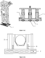
- FIG. 1 illustrating the pipe supporting arrangement (2) comprising main support frame (9) for pipes, spring arrangement (6) at bottom of the main support frame (9), ball transfer unit comprising roller arrangement (7) below spring arrangement (6) and bottom plate (5) for rigid connection to bridge structure.
- FIG 5 illustrating different embodiments of the external fixed pipe supporting arrangement of the piping system, adapted to receive plurality of pipes.
- the fixed support structure (1) has zero degree of freedom and functions as anchor for all pipes. These supporting arrangement (1) is designed to withstand all loads and reactions of the supported pipes.
- FIG. 6 illustrating different embodiments of the sliding pipe arrangement in accordance to the subject matter of the present invention.
- the main metal frame (9) supports the pipes.
- the pipes are supported through multiple openings (10).
- the structural members of these supports are designed so as to function and withstand maximum loading conditions.
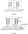
- the lower portion of the supporting arrangement consists of three plates, bottom (5) and middle plates (4) are connected to each other by rollers (7) while middle (4) and upper plate (3) is connected by spring arrangement (6).
- the different layout of the pipes, along with the layout of the springs and the ball transfer layout has been illustrated.
- Figures 6(a)-(b) illustrate external sliding pipe supporting arrangement providing displacement decoupling facility by attenuating or isolating axial, lateral and vertical displacement.
- Figures 6(c)-(d) illustrate external sliding pipe supporting arrangement providing displacement decoupling facility by attenuating or isolating axial and lateral displacement.
- the sliding pipe supporting arrangement for jacketed cryogenic piping system isolates or attenuates differential displacement in multiple directions.
- the design of sliding piping supporting arrangement provides for isolation of lateral (horizontal) and vertical differential movements during SL-2 type seismic event (max. acceleration of 8.6 G vertically, 2.1 G and 5 G in horizontal directions).
- the support is common for two vacuum jacketed cryolines and one bare pipe.
- the supporting arrangement (2) is designed to minimize its moments at the centre of gravity. Further, the supporting arrangement (2) also sustains accidental case of "loss of insulation vacuum of one cryoline" where the outer jacket pipe temperature of the cryoline can decrease locally up to -172°C, thereby achieving seismic-safe piping systems.
- expansion joint arrangement like bellows (8) are used between two pipe segments to isolate axial displacements. Local support of each line has been designed to slide axially. Since magnitude of axial displacement is large and coupled with the thermal contraction, multiple bellows in series compensate the total axial displacement of the piping system.
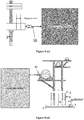
- FIG 7 illustrating the sliding support arrangement and the bellows arrangement for thermal compensation of process pipe.
- flexible hoses are used and bellows for process pipe have been used to isolate the thermal contraction and differential displacement as well.
- External bellows for Outer Vacuum Jacket (OVJ) isolate or attenuate differential displacements and contraction in case of loss of insulation vacuum for vacuum jacketed Group Y cryolines.
- External bellows for OVJ are placed in series between two fixed supports. Bellows on outer vacuum jacket as well as on non-vacuum jacketed lines with external sleeve are provided to prevent lateral displacement as well as lateral load on bellows.
- OVJ Outer Vacuum Jacket
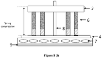
- FIGS 8 (a)-(i) illustrating the experimental setup and the verifying the functioning of the displacement decoupling provided by the external sliding pipe supporting arrangement under applied force (by using turnbuckle or weight) in each direction.
- turnbuckle has been placed along the line axis.
- Axial force has been applied on line by means of attaching a turnbuckle as shown in figure 8 (a) .
- Initial reading with reference to datum consideration has been recorded as in figure 8 (b) .
- Final reading after applying the axial force has been recorded as shown in figure 8 (c) .
- For lateral movement turnbuckle has been placed perpendicular to the line axis.
- the supporting arrangement (2) is designed to take care of maximum differential displacements of ⁇ 153 mm in lateral and ⁇ 56 mm in vertical direction. The tests have been performed and Table-1 shows the results obtained from this tests. Sr. No. Direction Initial Reading (mm) Final Reading (mm) Differential displacement (mm) Method of Force applied 1 Axial 50 85 35 By means of turnbuckle 2 Lateral 50 125 75 By means of turnbuckle 3 Vertical 315 305 10 By means of external weight
Landscapes
- Engineering & Computer Science (AREA)
- General Engineering & Computer Science (AREA)
- Mechanical Engineering (AREA)
- Supports For Pipes And Cables (AREA)
- Joints Allowing Movement (AREA)
Description
- The present invention in general relates to the field of piping systems, and in particular to a displacement decoupling arrangement for a piping system.
- General piping systems and unidirectional movable piping supports of conventional piping systems are generally designed for seismic events as per the local geographical conditions, with fixed supports, or movable support absorbing displacements in just one direction.
- The conventional seismic decoupling solutions are for the bare process pipes or buildings structures. A pipe running from an equipment A which is directly connected to ground to another equipment B, is connected to ground via seismic pads. There are differential movements in multiple directions between equipment A and equipment B during the seismic events. Such a movement can cause failure of the piping system if sufficient flexibility in multiple directions is not provided in the piping system.
- When two adjacent buildings or structures have different responses to seismic event, the rigid piping connecting the two buildings or structures demands sufficient flexibility in multiple directions so that pipes do not break during the seismic event due to large differential movements of buildings or structures it is connected with. Seismic events pose even more complex problems to jacketed piping with vacuum in annular space and fluid at cryogenic temperatures in inner pipe
JP 2000 356295 EP 0 439 272 relates to a vibration proofing device such that a an upper strucure is swingably supported on alower structure thereby isolating the upper structure from vibration such as caused by earthquakes.US 4 554 767 discloses a base isolation system for a structure for protecting against earthquakes. - Accordingly, there is a need for a displacement decoupling arrangement in the supporting structure of pipes which helps to achieve safe design of jacketed cryogenic piping arrangement for large differential displacements in multiple directions during seismic events.
- The following presents a simplified summary of the invention in order to provide a basic understanding of some aspects of the invention. This summary is not an extensive overview of the present invention. It is not intended to identify the key/critical elements of the invention or to delineate the scope of the invention. Its sole purpose is to present some concept of the invention in a simplified form as a prelude to a more detailed description of the invention presented later.
- An object of the present invention is to provide a sliding pipe supporting arrangement adapted to receive and support at least one pipe or jacketed pipe assembly.
- Another object of the present invention is to provide a piping system for jacketed cryogenic piping arrangement comprising a sliding pipe supporting arrangement.
- In accordance with an aspect of the present disclosure, is to provide a displacement decoupling arrangement for piping systems which is a sliding pipe supporting arrangement adapted to receive and support at least one pipe or pipe assembly, said arrangement comprising main support means comprising at least one opening to support a pipe, an assembly of spring arrangement and ball transfer unit, mechanically coupled to the main support means so as to isolate differential displacement in lateral (Y-direction) and vertical direction (Z-direction) of the said pipe, said assembly unit comprising a top plate, middle plate and a bottom plate, wherein the spring arrangement comprises a plurality of springs substantially positioned in between the top plate and the middle plate facilitating the vertical displacement of the said pipe, and wherein the ball transfer unit comprises plural rollers mechanically positioned between the bottom plate and middle plate facilitating lateral displacement of the said pipe and an expansion joint arrangement operably placed in between pipe lengths of a pipe to attenuate the axial displacement (X-direction) of the said pipe.
- In another aspect of the present invention, is to provide a piping system for jacketed cryogenic piping arrangement comprising a sliding pipe supporting arrangement and a fixed pipe supporting arrangement, adapted to receive and support two vacuum jacketed cryolines and one bare pipe, wherein the sliding pipe supporting arrangement operates at very low temperatures, where the outer jacket pipe temperature of the cryoline decrease up to approximately -172° C due to loss of insulation vacuum of the said cryoline. The sliding pipe supporting arrangement operates under SL-2 type seismic event, having an acceleration of 8.6G in the vertical direction (Z-direction), 2.1G and 5G in the horizontal direction (X and Y directions).
- Other aspects, advantages, and salient features of the invention will become apparent to those skilled in the art from the following detailed description, which, taken in conjunction with the annexed drawings, discloses exemplary embodiments of the invention.
- The above and other aspects, features and advantages of the embodiments of the present disclosure will be more apparent in the following description taken in conjunction with the accompanying drawings, in which:
-
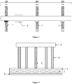
Figure 1 illustrates a small segment of the piping system with one external fixed support and external sliding support, according to an implementation of the present invention. -
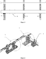
Figure 2 illustrates an arrangement in a piping system to attenuate lateral and vertical displacement, according to an implementation of the present invention. -
Figure 3 illustrates an arrangement in a piping system to attenuate axial displacement, according to an implementation of the present invention. -
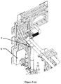
Figures 4 illustrates a model of the support arrangement in a piping system, according to an implementation of the present invention. -
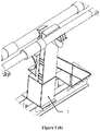
Figures 5 (a)-(b) illustrate the different embodiments of the external fixed support, according to an implementation of the present invention. -
Figures 6(a)-(d) illustrate the different embodiments of the external sliding pipe support arrangement, according to an implementation of the present invention. -
Figure 7 (a)-(b) illustrate the expansion joint location in a piping system for attenuating axial displacement, according to an implementation of the present invention. -
Figures 8 (a)-(i) illustrate the experimental setup and the verification of the functioning of the external fixed support, according to an implementation of the present invention. - Persons skilled in the art will appreciate that elements in the figures are illustrated for simplicity and clarity and may have not been drawn to scale. For example, the dimensions of some of the elements in the figure may be exaggerated relative to other elements to help to improve understanding of various exemplary embodiments of the present disclosure. Throughout the drawings, it should be noted that like reference numbers are used to depict the same or similar elements, features, and structures.
- The following description with reference to the accompanying drawings is provided to assist in a comprehensive understanding of various embodiments of the present disclosure as defined by the claims and their equivalents. It includes various specific details to assist in that understanding but these are to be regarded as merely exemplary. Accordingly, those of ordinary skill in the art will recognize that various changes and modifications of the various embodiments described herein can be made without departing from the scope of the present disclosure. In addition, descriptions of well-known functions and constructions may be omitted for clarity and conciseness.
- The terms and words used in the following description and claims are not limited to the bibliographical meanings, but, are merely used by the inventor to enable a clear and consistent understanding of the present disclosure. Accordingly, it should be apparent to those skilled in the art that the following description of various embodiments of the present disclosure is provided for illustration purpose only and not for the purpose of limiting the present disclosure as defined by the appended claims.
- It is to be understood that the singular forms "a," "an," and "the" include plural referents unless the context clearly dictates otherwise. Thus, for example, reference to "a component surface" includes reference to one or more of such surfaces.
- All terms (including technical and scientific terms) used herein have the same meaning as commonly understood by one of ordinary skill in the art to which various embodiments belong. Further, the meaning of terms or words used in the specification and the claims should not be limited to the literal or commonly employed sense, but should be construed in accordance with the spirit of the disclosure to most properly describe the present disclosure.
- The terminology used herein is for the purpose of describing particular various embodiments only and is not intended to be limiting of various embodiments. As used herein, the singular forms "a," "an" and "the" are intended to include the plural forms as well, unless the context clearly indicates otherwise. It will be further understood that the terms "comprises" and/or "comprising" used herein specify the presence of stated features, integers, steps, operations, members, components, and/or groups thereof, but do not preclude the presence or addition of one or more other features, integers, steps, operations, members, components, and/or groups thereof. Also, Expressions such as "at least one of," when preceding a list of elements, modify the entire list of elements and do not modify the individual elements of the list.
- The present disclosure will now be described more fully with reference to the accompanying drawings, in which various embodiments of the present disclosure are shown. The present disclosure may, however, be embodied in many different forms and should not be construed as being limited to the various embodiments set forth herein, rather, these various embodiments are provided so that this disclosure will be thorough and complete, and will fully convey the present disclosure. Furthermore, a detailed description of other parts will not be provided not to make the present disclosure unclear. Like reference numerals in the drawings refer to like elements throughout.
- The subject invention lies in providing a sliding pipe supporting arrangement, facilitating displacement decoupling for piping systems for seismic events as per the local geographic conditions. The overall piping system layout along with external fixed supports and the sliding pipe supporting arrangement provides attenuation of the displacement of the piping system in multiple directions, thereby ensuring overall safety.
- According to one implementation of the present invention a sliding pipe supporting arrangement (2) adapted to receive and support at least one pipe or pipe assembly, said arrangement comprising main support means (9) comprising at least one opening to support a pipe, an assembly of spring arrangement (6) and ball transfer unit (7), mechanically coupled to the main support means (9) so as to isolate differential displacement in lateral (Y-direction) and vertical direction (Z-direction) of the said pipe, said assembly unit comprising a top plate (3), middle plate (4) and a bottom plate (5), wherein the spring arrangement (6) comprises a plurality of springs substantially positioned in between the top plate (3) and the middle plate (4) facilitating the vertical displacement of the said pipe, and wherein the ball transfer unit (7) comprises plural rollers mechanically positioned between the middle plate (4) and bottom plate (5) facilitating lateral displacement of the said pipe; and an expansion joint arrangement (8) operably placed in between pipe lengths of a pipe to attenuate the axial displacement (X-direction) of the said pipe.
- In another embodiment in accordance to the subject matter of the present invention, it provides innovative sliding pipe supporting arrangement for jacketed cryogenic piping system to take care of differential displacement in multiple directions during seismic events.
- In another embodiment in accordance to the subject matter of the present invention, the seismic decoupling system as provided by the sliding pipe supporting arrangement of the present invention is designed for vacuum jacketed pipes along with bare pipes. The sliding pipe supporting arrangement attenuates the seismic displacements and the thermal contractions of the cryogenic pipes, thereby ensuring functionality of the cryolines remains intact during and after a seismic event.
- In another embodiment in accordance to the subject matter of the present invention, flexibility in a piping system is provided by isolating the differential movement on the pipe itself by incorporating flexible bellows and hoses in the pipes.
- In another embodiment in accordance to the subject matter of the present invention, isolating the differential movement of the pipes at the sliding pipe supporting arrangement is implemented by using springs or bearings and the like in the supporting arrangement.
- In another embodiment in accordance to the subject matter of the present invention, the displacement decoupling system provided by the sliding pipe supporting arrangement isolates horizontal axial differential movement on the pipe itself using bellows and isolates lateral (horizontal) and vertical differential movement at the sliding external supporting arrangement using rollers and springs respectively. Thus the displacement in all the three directions during a seismic event is isolated or attenuated both in the pipes and in the sliding pipe supporting arrangement.
- The external sliding pipe supporting arrangement attenuates or isolates the differential movement in lateral and vertical direction using standard roller bearing and standard springs respectively. The combination of the spring assembly and the ball transfer unit comprising of the rollers, integrated in the supporting structure to support multiple pipes facilitates the attenuation of the displacement encountered by a piping system in multiple directions.
- In another embodiment in accordance to the subject matter of the present invention, the supporting arrangement also ensures that cryogenic temperature does not reach to the springs or bearings in case of loss of insulation vacuum in cryolines.
- In another embodiment in accordance to the subject matter of the present invention, the displacement of pipes in axial (X direction) is attenuated or isolated by the metallic bellows connecting individual pipe lengths in the entire piping system, of a jacketed cryogenic piping system.
- Reference has been made to
figures 1 and 2 , illustrating the pipe supporting arrangement (2) comprising main support frame (9) for pipes, spring arrangement (6) at bottom of the main support frame (9), ball transfer unit comprising roller arrangement (7) below spring arrangement (6) and bottom plate (5) for rigid connection to bridge structure. - Reference has been made to
figure 5 , illustrating different embodiments of the external fixed pipe supporting arrangement of the piping system, adapted to receive plurality of pipes. The fixed support structure (1) has zero degree of freedom and functions as anchor for all pipes. These supporting arrangement (1) is designed to withstand all loads and reactions of the supported pipes. - Reference has been made to
figure 6 , illustrating different embodiments of the sliding pipe arrangement in accordance to the subject matter of the present invention. The main metal frame (9) supports the pipes. The pipes are supported through multiple openings (10). The structural members of these supports are designed so as to function and withstand maximum loading conditions. The lower portion of the supporting arrangement consists of three plates, bottom (5) and middle plates (4) are connected to each other by rollers (7) while middle (4) and upper plate (3) is connected by spring arrangement (6). The different layout of the pipes, along with the layout of the springs and the ball transfer layout has been illustrated.Figures 6(a)-(b) illustrate external sliding pipe supporting arrangement providing displacement decoupling facility by attenuating or isolating axial, lateral and vertical displacement.Figures 6(c)-(d) illustrate external sliding pipe supporting arrangement providing displacement decoupling facility by attenuating or isolating axial and lateral displacement. - In another embodiment in accordance to the subject matter of the present invention, the sliding pipe supporting arrangement for jacketed cryogenic piping system isolates or attenuates differential displacement in multiple directions. The design of sliding piping supporting arrangement provides for isolation of lateral (horizontal) and vertical differential movements during SL-2 type seismic event (max. acceleration of 8.6 G vertically, 2.1 G and 5 G in horizontal directions). The support is common for two vacuum jacketed cryolines and one bare pipe. The supporting arrangement (2) is designed to minimize its moments at the centre of gravity. Further, the supporting arrangement (2) also sustains accidental case of "loss of insulation vacuum of one cryoline" where the outer jacket pipe temperature of the cryoline can decrease locally up to -172°C, thereby achieving seismic-safe piping systems.
- Referring to
figure 3 , expansion joint arrangement like bellows (8) are used between two pipe segments to isolate axial displacements. Local support of each line has been designed to slide axially. Since magnitude of axial displacement is large and coupled with the thermal contraction, multiple bellows in series compensate the total axial displacement of the piping system. - In another embodiment in accordance to the subject matter of the present invention, reference has been made to
figure 7 , illustrating the sliding support arrangement and the bellows arrangement for thermal compensation of process pipe. For thermal compensation, flexible hoses are used and bellows for process pipe have been used to isolate the thermal contraction and differential displacement as well. External bellows for Outer Vacuum Jacket (OVJ) isolate or attenuate differential displacements and contraction in case of loss of insulation vacuum for vacuum jacketed Group Y cryolines. External bellows for OVJ are placed in series between two fixed supports. Bellows on outer vacuum jacket as well as on non-vacuum jacketed lines with external sleeve are provided to prevent lateral displacement as well as lateral load on bellows. - Reference has been made to
figures 8 (a)-(i) , illustrating the experimental setup and the verifying the functioning of the displacement decoupling provided by the external sliding pipe supporting arrangement under applied force (by using turnbuckle or weight) in each direction. To check axial movement turnbuckle has been placed along the line axis. Axial force has been applied on line by means of attaching a turnbuckle as shown infigure 8 (a) . Initial reading with reference to datum consideration has been recorded as infigure 8 (b) . Final reading after applying the axial force has been recorded as shown infigure 8 (c) . For lateral movement turnbuckle has been placed perpendicular to the line axis. Lateral force has been applied on line by means of attaching the turnbuckle as shown infigure 8 (d) . Initial and final reading with reference to datum consideration has been recorded as infigures 8 (e)-(f) . To check vertical movement vertical force has been applied on sliding support by means of external weight as shown infigure 8 (g) . Displacement value for after compression of springs has been recorded as shown infigure 8 (i) . - The supporting arrangement (2) is designed to take care of maximum differential displacements of ± 153 mm in lateral and ± 56 mm in vertical direction. The tests have been performed and Table-1 shows the results obtained from this tests.
Sr. No. Direction Initial Reading (mm) Final Reading (mm) Differential displacement (mm) Method of Force applied 1 Axial 50 85 35 By means of turnbuckle 2 Lateral 50 125 75 By means of turnbuckle 3 Vertical 315 305 10 By means of external weight - The test setup of displacement decoupling has been fabricated and successfully tested. External force in each direction has been applied and it has been checked that displacement decoupling system containing ball transfer units, springs and bellows is able to absorb the displacement without damaging or failure of the lines.
- Some of the non-limiting advantages of the present invention are:
- 1. Helps to achieve safe design of piping system (in particular cryogenic jacketed piping) under severe seismic conditions by decoupling the differential displacements in multiple directions.
- 2. Attenuating displacement of pipes under seismic conditions in all 3 directions (X, Y and Z) including combination of such displacements, thereby improving sustainability of pipelines in seismic regions.
- Although a sliding pipe supporting arrangement adapted to receive and support at least one pipe or pipe assembly has been described in language specific to structural features, it is to be understood that the embodiments disclosed in the above section are not necessarily limited to the specific methods or devices described herein. Rather, the specific features are disclosed as examples of implementations of a sliding pipe supporting arrangement adapted to receive and support at least one pipe or pipe assembly.
Claims (4)
- A sliding pipe supporting arrangement (2) adapted to receive and support at least one pipe or jacketed pipe assembly, said arrangement comprising :main support means (9) comprising at least one opening to support a pipecharacterized in that it comprises:an assembly of spring arrangement (6) and ball transfer unit (7), mechanically coupled to the main support means (9) so as to isolate differential displacement in lateral (Y-direction) and vertical direction (Z-direction) of the said pipe, said assembly unit comprising a top plate (3), middle plate (4) and a bottom plate (5), wherein the spring arrangement (6) comprises a plurality of springs substantially positioned in between the top plate (3) and the middle plate (4) facilitating the vertical displacement of the said pipe, and wherein the ball transfer unit (7) comprises plural rollers mechanically positioned between the middle plate (4) and bottom plate (5) facilitating lateral displacement of the said pipe; andan expansion joint arrangement (8) operably placed in between pipe lengths of a pipe to attenuate the axial displacement (X-direction) of the said pipe.
- A piping system for jacketed cryogenic piping arrangement comprising :a sliding pipe supporting arrangement (2) adapted to receive and support at least one pipe or jacketed pipe assembly, said arrangement comprising main support means (9) comprising at least one opening to support a pipe characterized in that it comprisesan assembly of spring arrangement (6) and ball transfer unit (7), mechanically coupled to the main support means (9) so as to isolate differential displacement in lateral (Y-direction) and vertical direction (Z-direction) of the said pipe, said assembly unit comprising a top plate (3), middle plate (4) and a bottom plate (5), wherein the spring arrangement (6) comprises a plurality of springs substantially positioned in between the top plate (3) and the middle plate (4) facilitating the vertical displacement of the said pipe, and wherein the ball transfer unit (7) comprises plural rollers mechanically positioned between the middle plate (4) and bottom plate (5) facilitating lateral displacement of the said pipe;an expansion joint arrangement (8) operably placed in between pipe lengths of a pipe to attenuate the axial displacement (X-direction) of the said pipe; anda fixed pipe supporting arrangement (1), adapted to receive and support a plurality of vacuum jacketed cryolines and a bare pipe.
- The piping system as claimed in claim 2, wherein the sliding pipe supporting arrangement (2) operates at very low temperatures, where outer jacket pipe temperature of the cryoline decrease up to approximately -172° C due to loss of insulation vacuum of the said cryoline.
- The piping system as claimed in claim 2, wherein the sliding pipe supporting arrangement (2) operates under SL-2 type seismic event, having an acceleration of 8.6G in the vertical direction (Z-direction), 2.1G and 5G in the horizontal direction (X and Y directions).
Applications Claiming Priority (1)
| Application Number | Priority Date | Filing Date | Title |
|---|---|---|---|
| IN201821029220 | 2018-08-03 |
Publications (2)
| Publication Number | Publication Date |
|---|---|
| EP3604713A1 EP3604713A1 (en) | 2020-02-05 |
| EP3604713B1 true EP3604713B1 (en) | 2021-02-24 |
Family
ID=64048972
Family Applications (1)
| Application Number | Title | Priority Date | Filing Date |
|---|---|---|---|
| EP18203798.6A Active EP3604713B1 (en) | 2018-08-03 | 2018-10-31 | Displacement decoupling arrangement for pipingsystems |
Country Status (2)
| Country | Link |
|---|---|
| US (1) | US10738914B2 (en) |
| EP (1) | EP3604713B1 (en) |
Families Citing this family (2)
| Publication number | Priority date | Publication date | Assignee | Title |
|---|---|---|---|---|
| CN114738601B (en) * | 2022-03-30 | 2024-05-24 | 郑州水务建筑工程股份有限公司 | A fixed protective device for water conservancy pipeline |
| CN114542812B (en) * | 2022-03-31 | 2023-08-11 | 浙江友瑞建设工程有限公司 | Hydraulic pipeline bracket for building engineering construction |
Family Cites Families (12)
| Publication number | Priority date | Publication date | Assignee | Title |
|---|---|---|---|---|
| US2756014A (en) * | 1954-03-15 | 1956-07-24 | C H Leibfried Mfg Corp | Spring hangers |
| US4069992A (en) * | 1976-09-13 | 1978-01-24 | Corner & Lada Co., Inc. | Travel stop |
| IL59861A0 (en) * | 1980-04-18 | 1980-06-30 | Popper Eng Ltd | Load supporting spring system |
| US4554767A (en) * | 1981-02-05 | 1985-11-26 | Ikonomou Aristarchos S | Earthquake guarding system |
| US4576356A (en) * | 1983-02-03 | 1986-03-18 | Kucera Richard J | Pipe-vibration reducer |
| US5009386A (en) * | 1989-06-01 | 1991-04-23 | Berger Richard C | Pipe hanger and support |
| EP0439272B1 (en) * | 1990-01-20 | 1996-05-29 | Sumitomo Gomu Kogyo Kabushiki Kaisha | Vibration-proofing device |
| JP2978732B2 (en) * | 1994-12-12 | 1999-11-15 | 核燃料サイクル開発機構 | Common floor type vertical seismic isolation structure for reactor equipment |
| JP4216955B2 (en) * | 1999-06-16 | 2009-01-28 | 株式会社Ork | Seismic isolation piping system and bellows type expansion joint with legs |
| WO2015147681A1 (en) * | 2014-03-28 | 2015-10-01 | Открытое акционерное общество "Акционерная компания по транспорту нефти "Транснефть" (ОАО "АК "Транснефть") | Movable pipeline-support and support assembly thereof |
| EP3205917B1 (en) * | 2016-02-12 | 2018-08-01 | Walter Stauffenberg Gmbh & Co. Kg | Device for fixing pipes and hoses |
| US20190135202A1 (en) * | 2017-11-06 | 2019-05-09 | Albert Korson | Elevated cradle for supporting conduits extending between a vehicle tractor and trailer |
-
2018
- 2018-10-31 EP EP18203798.6A patent/EP3604713B1/en active Active
- 2018-11-02 US US16/179,035 patent/US10738914B2/en active Active
Non-Patent Citations (1)
| Title |
|---|
| None * |
Also Published As
| Publication number | Publication date |
|---|---|
| EP3604713A1 (en) | 2020-02-05 |
| US20200041043A1 (en) | 2020-02-06 |
| US10738914B2 (en) | 2020-08-11 |
Similar Documents
| Publication | Publication Date | Title |
|---|---|---|
| US5261200A (en) | Vibration-proofing device | |
| US10738914B2 (en) | Displacement decoupling arrangement for piping systems | |
| CN112523363B (en) | Three-dimensional vibration isolation support | |
| JP6949404B2 (en) | New 3D anti-vibration device | |
| US20170260767A1 (en) | Support structure | |
| EP0439272B1 (en) | Vibration-proofing device | |
| CN109555009B (en) | A Support and Beam Body Seismic Isolation Structural System and Its Application | |
| US4593526A (en) | Steam turbine system installation with protection of piping against seismic loading | |
| KR20110072410A (en) | Seismic isolation device | |
| US20150128510A1 (en) | Polygonal seismic isolation systems | |
| CN109487703B (en) | A function-separated self-resetting shock-absorbing bridge and its installation method | |
| JP6895737B2 (en) | Installation structure of building oil damper | |
| JP6855824B2 (en) | Position adjustment method of seismic isolated building and position adjustment structure of seismic isolated building | |
| JP5749606B2 (en) | Seismic isolation method for existing buildings | |
| JP7467460B2 (en) | Vibration-proof bearing | |
| CN113882246A (en) | Double-guide tensile anti-overturning shock insulation rubber support | |
| JPS61215825A (en) | Anti-seismic supporting device | |
| CN120467891B (en) | A model box for simulating coseismic stick-slip faulting and its usage method | |
| CN220469164U (en) | Curved surface sliding type shock insulation joint structure | |
| Oda et al. | The pipeline design method against large fault displacement | |
| CN117702940A (en) | Three-dimensional shock insulation device | |
| JPH03217533A (en) | Earthquake-isolating supporter | |
| CN115540942B (en) | Monitoring vibration isolation device | |
| JP2020133219A (en) | Lock mechanism | |
| JPH0344920Y2 (en) |
Legal Events
| Date | Code | Title | Description |
|---|---|---|---|
| PUAI | Public reference made under article 153(3) epc to a published international application that has entered the european phase |
Free format text: ORIGINAL CODE: 0009012 |
|
| STAA | Information on the status of an ep patent application or granted ep patent |
Free format text: STATUS: REQUEST FOR EXAMINATION WAS MADE |
|
| 17P | Request for examination filed |
Effective date: 20190107 |
|
| AK | Designated contracting states |
Kind code of ref document: A1 Designated state(s): AL AT BE BG CH CY CZ DE DK EE ES FI FR GB GR HR HU IE IS IT LI LT LU LV MC MK MT NL NO PL PT RO RS SE SI SK SM TR |
|
| AX | Request for extension of the european patent |
Extension state: BA ME |
|
| GRAP | Despatch of communication of intention to grant a patent |
Free format text: ORIGINAL CODE: EPIDOSNIGR1 |
|
| STAA | Information on the status of an ep patent application or granted ep patent |
Free format text: STATUS: GRANT OF PATENT IS INTENDED |
|
| RIC1 | Information provided on ipc code assigned before grant |
Ipc: F16L 51/02 20060101ALI20200910BHEP Ipc: E04H 9/02 20060101AFI20200910BHEP Ipc: F16L 3/20 20060101ALI20200910BHEP Ipc: F16L 3/205 20060101ALI20200910BHEP Ipc: F16L 27/11 20060101ALI20200910BHEP |
|
| INTG | Intention to grant announced |
Effective date: 20201014 |
|
| RIN1 | Information on inventor provided before grant (corrected) |
Inventor name: VAGHELA, HITENSINH B. Inventor name: KANZARIA, HIREN V. Inventor name: CHOUKEKAR, KETAN D. Inventor name: PRAJAPATI, DHARA G. Inventor name: THEKDI, MANAN R. Inventor name: SHAH, NITIN D. Inventor name: DODIYA, DARSHAN M. Inventor name: GEHANI, VIJAY S. Inventor name: JOSHI, BHUMIKA H. Inventor name: PANJWANI, RAJKUMAR L. Inventor name: KUMAR, UDAY Inventor name: SARKAR, BISWANATH Inventor name: JADON, MOHIT Inventor name: VYAS, HARDIK R. |
|
| GRAS | Grant fee paid |
Free format text: ORIGINAL CODE: EPIDOSNIGR3 |
|
| GRAA | (expected) grant |
Free format text: ORIGINAL CODE: 0009210 |
|
| STAA | Information on the status of an ep patent application or granted ep patent |
Free format text: STATUS: THE PATENT HAS BEEN GRANTED |
|
| AK | Designated contracting states |
Kind code of ref document: B1 Designated state(s): AL AT BE BG CH CY CZ DE DK EE ES FI FR GB GR HR HU IE IS IT LI LT LU LV MC MK MT NL NO PL PT RO RS SE SI SK SM TR |
|
| REG | Reference to a national code |
Ref country code: CH Ref legal event code: EP |
|
| REG | Reference to a national code |
Ref country code: AT Ref legal event code: REF Ref document number: 1364616 Country of ref document: AT Kind code of ref document: T Effective date: 20210315 |
|
| REG | Reference to a national code |
Ref country code: IE Ref legal event code: FG4D |
|
| REG | Reference to a national code |
Ref country code: DE Ref legal event code: R096 Ref document number: 602018012975 Country of ref document: DE |
|
| REG | Reference to a national code |
Ref country code: CH Ref legal event code: NV Representative=s name: RAPISARDI INTELLECTUAL PROPERTY SA, CH |
|
| REG | Reference to a national code |
Ref country code: LT Ref legal event code: MG9D |
|
| REG | Reference to a national code |
Ref country code: NL Ref legal event code: MP Effective date: 20210224 |
|
| PG25 | Lapsed in a contracting state [announced via postgrant information from national office to epo] |
Ref country code: FI Free format text: LAPSE BECAUSE OF FAILURE TO SUBMIT A TRANSLATION OF THE DESCRIPTION OR TO PAY THE FEE WITHIN THE PRESCRIBED TIME-LIMIT Effective date: 20210224 Ref country code: GR Free format text: LAPSE BECAUSE OF FAILURE TO SUBMIT A TRANSLATION OF THE DESCRIPTION OR TO PAY THE FEE WITHIN THE PRESCRIBED TIME-LIMIT Effective date: 20210525 Ref country code: HR Free format text: LAPSE BECAUSE OF FAILURE TO SUBMIT A TRANSLATION OF THE DESCRIPTION OR TO PAY THE FEE WITHIN THE PRESCRIBED TIME-LIMIT Effective date: 20210224 Ref country code: BG Free format text: LAPSE BECAUSE OF FAILURE TO SUBMIT A TRANSLATION OF THE DESCRIPTION OR TO PAY THE FEE WITHIN THE PRESCRIBED TIME-LIMIT Effective date: 20210524 Ref country code: NO Free format text: LAPSE BECAUSE OF FAILURE TO SUBMIT A TRANSLATION OF THE DESCRIPTION OR TO PAY THE FEE WITHIN THE PRESCRIBED TIME-LIMIT Effective date: 20210524 Ref country code: PT Free format text: LAPSE BECAUSE OF FAILURE TO SUBMIT A TRANSLATION OF THE DESCRIPTION OR TO PAY THE FEE WITHIN THE PRESCRIBED TIME-LIMIT Effective date: 20210624 Ref country code: LT Free format text: LAPSE BECAUSE OF FAILURE TO SUBMIT A TRANSLATION OF THE DESCRIPTION OR TO PAY THE FEE WITHIN THE PRESCRIBED TIME-LIMIT Effective date: 20210224 |
|
| REG | Reference to a national code |
Ref country code: AT Ref legal event code: MK05 Ref document number: 1364616 Country of ref document: AT Kind code of ref document: T Effective date: 20210224 |
|
| PG25 | Lapsed in a contracting state [announced via postgrant information from national office to epo] |
Ref country code: SE Free format text: LAPSE BECAUSE OF FAILURE TO SUBMIT A TRANSLATION OF THE DESCRIPTION OR TO PAY THE FEE WITHIN THE PRESCRIBED TIME-LIMIT Effective date: 20210224 Ref country code: PL Free format text: LAPSE BECAUSE OF FAILURE TO SUBMIT A TRANSLATION OF THE DESCRIPTION OR TO PAY THE FEE WITHIN THE PRESCRIBED TIME-LIMIT Effective date: 20210224 Ref country code: LV Free format text: LAPSE BECAUSE OF FAILURE TO SUBMIT A TRANSLATION OF THE DESCRIPTION OR TO PAY THE FEE WITHIN THE PRESCRIBED TIME-LIMIT Effective date: 20210224 Ref country code: RS Free format text: LAPSE BECAUSE OF FAILURE TO SUBMIT A TRANSLATION OF THE DESCRIPTION OR TO PAY THE FEE WITHIN THE PRESCRIBED TIME-LIMIT Effective date: 20210224 Ref country code: NL Free format text: LAPSE BECAUSE OF FAILURE TO SUBMIT A TRANSLATION OF THE DESCRIPTION OR TO PAY THE FEE WITHIN THE PRESCRIBED TIME-LIMIT Effective date: 20210224 |
|
| PG25 | Lapsed in a contracting state [announced via postgrant information from national office to epo] |
Ref country code: IS Free format text: LAPSE BECAUSE OF FAILURE TO SUBMIT A TRANSLATION OF THE DESCRIPTION OR TO PAY THE FEE WITHIN THE PRESCRIBED TIME-LIMIT Effective date: 20210624 |
|
| PG25 | Lapsed in a contracting state [announced via postgrant information from national office to epo] |
Ref country code: AT Free format text: LAPSE BECAUSE OF FAILURE TO SUBMIT A TRANSLATION OF THE DESCRIPTION OR TO PAY THE FEE WITHIN THE PRESCRIBED TIME-LIMIT Effective date: 20210224 Ref country code: SM Free format text: LAPSE BECAUSE OF FAILURE TO SUBMIT A TRANSLATION OF THE DESCRIPTION OR TO PAY THE FEE WITHIN THE PRESCRIBED TIME-LIMIT Effective date: 20210224 Ref country code: CZ Free format text: LAPSE BECAUSE OF FAILURE TO SUBMIT A TRANSLATION OF THE DESCRIPTION OR TO PAY THE FEE WITHIN THE PRESCRIBED TIME-LIMIT Effective date: 20210224 Ref country code: EE Free format text: LAPSE BECAUSE OF FAILURE TO SUBMIT A TRANSLATION OF THE DESCRIPTION OR TO PAY THE FEE WITHIN THE PRESCRIBED TIME-LIMIT Effective date: 20210224 |
|
| REG | Reference to a national code |
Ref country code: DE Ref legal event code: R097 Ref document number: 602018012975 Country of ref document: DE |
|
| PG25 | Lapsed in a contracting state [announced via postgrant information from national office to epo] |
Ref country code: RO Free format text: LAPSE BECAUSE OF FAILURE TO SUBMIT A TRANSLATION OF THE DESCRIPTION OR TO PAY THE FEE WITHIN THE PRESCRIBED TIME-LIMIT Effective date: 20210224 Ref country code: SK Free format text: LAPSE BECAUSE OF FAILURE TO SUBMIT A TRANSLATION OF THE DESCRIPTION OR TO PAY THE FEE WITHIN THE PRESCRIBED TIME-LIMIT Effective date: 20210224 Ref country code: DK Free format text: LAPSE BECAUSE OF FAILURE TO SUBMIT A TRANSLATION OF THE DESCRIPTION OR TO PAY THE FEE WITHIN THE PRESCRIBED TIME-LIMIT Effective date: 20210224 |
|
| PLBE | No opposition filed within time limit |
Free format text: ORIGINAL CODE: 0009261 |
|
| STAA | Information on the status of an ep patent application or granted ep patent |
Free format text: STATUS: NO OPPOSITION FILED WITHIN TIME LIMIT |
|
| PG25 | Lapsed in a contracting state [announced via postgrant information from national office to epo] |
Ref country code: ES Free format text: LAPSE BECAUSE OF FAILURE TO SUBMIT A TRANSLATION OF THE DESCRIPTION OR TO PAY THE FEE WITHIN THE PRESCRIBED TIME-LIMIT Effective date: 20210224 Ref country code: AL Free format text: LAPSE BECAUSE OF FAILURE TO SUBMIT A TRANSLATION OF THE DESCRIPTION OR TO PAY THE FEE WITHIN THE PRESCRIBED TIME-LIMIT Effective date: 20210224 |
|
| 26N | No opposition filed |
Effective date: 20211125 |
|
| PG25 | Lapsed in a contracting state [announced via postgrant information from national office to epo] |
Ref country code: SI Free format text: LAPSE BECAUSE OF FAILURE TO SUBMIT A TRANSLATION OF THE DESCRIPTION OR TO PAY THE FEE WITHIN THE PRESCRIBED TIME-LIMIT Effective date: 20210224 |
|
| PG25 | Lapsed in a contracting state [announced via postgrant information from national office to epo] |
Ref country code: IS Free format text: LAPSE BECAUSE OF FAILURE TO SUBMIT A TRANSLATION OF THE DESCRIPTION OR TO PAY THE FEE WITHIN THE PRESCRIBED TIME-LIMIT Effective date: 20210624 |
|
| REG | Reference to a national code |
Ref country code: BE Ref legal event code: MM Effective date: 20211031 |
|
| PG25 | Lapsed in a contracting state [announced via postgrant information from national office to epo] |
Ref country code: MC Free format text: LAPSE BECAUSE OF FAILURE TO SUBMIT A TRANSLATION OF THE DESCRIPTION OR TO PAY THE FEE WITHIN THE PRESCRIBED TIME-LIMIT Effective date: 20210224 |
|
| PG25 | Lapsed in a contracting state [announced via postgrant information from national office to epo] |
Ref country code: LU Free format text: LAPSE BECAUSE OF NON-PAYMENT OF DUE FEES Effective date: 20211031 Ref country code: BE Free format text: LAPSE BECAUSE OF NON-PAYMENT OF DUE FEES Effective date: 20211031 |
|
| PG25 | Lapsed in a contracting state [announced via postgrant information from national office to epo] |
Ref country code: IE Free format text: LAPSE BECAUSE OF NON-PAYMENT OF DUE FEES Effective date: 20211031 |
|
| P01 | Opt-out of the competence of the unified patent court (upc) registered |
Effective date: 20230515 |
|
| GBPC | Gb: european patent ceased through non-payment of renewal fee |
Effective date: 20221031 |
|
| PG25 | Lapsed in a contracting state [announced via postgrant information from national office to epo] |
Ref country code: CY Free format text: LAPSE BECAUSE OF FAILURE TO SUBMIT A TRANSLATION OF THE DESCRIPTION OR TO PAY THE FEE WITHIN THE PRESCRIBED TIME-LIMIT Effective date: 20210224 |
|
| PG25 | Lapsed in a contracting state [announced via postgrant information from national office to epo] |
Ref country code: HU Free format text: LAPSE BECAUSE OF FAILURE TO SUBMIT A TRANSLATION OF THE DESCRIPTION OR TO PAY THE FEE WITHIN THE PRESCRIBED TIME-LIMIT; INVALID AB INITIO Effective date: 20181031 |
|
| PG25 | Lapsed in a contracting state [announced via postgrant information from national office to epo] |
Ref country code: GB Free format text: LAPSE BECAUSE OF NON-PAYMENT OF DUE FEES Effective date: 20221031 |
|
| PG25 | Lapsed in a contracting state [announced via postgrant information from national office to epo] |
Ref country code: MK Free format text: LAPSE BECAUSE OF FAILURE TO SUBMIT A TRANSLATION OF THE DESCRIPTION OR TO PAY THE FEE WITHIN THE PRESCRIBED TIME-LIMIT Effective date: 20210224 |
|
| PG25 | Lapsed in a contracting state [announced via postgrant information from national office to epo] |
Ref country code: TR Free format text: LAPSE BECAUSE OF FAILURE TO SUBMIT A TRANSLATION OF THE DESCRIPTION OR TO PAY THE FEE WITHIN THE PRESCRIBED TIME-LIMIT Effective date: 20210224 |
|
| PG25 | Lapsed in a contracting state [announced via postgrant information from national office to epo] |
Ref country code: MT Free format text: LAPSE BECAUSE OF FAILURE TO SUBMIT A TRANSLATION OF THE DESCRIPTION OR TO PAY THE FEE WITHIN THE PRESCRIBED TIME-LIMIT Effective date: 20210224 |
|
| REG | Reference to a national code |
Ref country code: CH Ref legal event code: U11 Free format text: ST27 STATUS EVENT CODE: U-0-0-U10-U11 (AS PROVIDED BY THE NATIONAL OFFICE) Effective date: 20251115 |
|
| PGFP | Annual fee paid to national office [announced via postgrant information from national office to epo] |
Ref country code: DE Payment date: 20251028 Year of fee payment: 8 |
|
| PGFP | Annual fee paid to national office [announced via postgrant information from national office to epo] |
Ref country code: IT Payment date: 20251030 Year of fee payment: 8 |
|
| PGFP | Annual fee paid to national office [announced via postgrant information from national office to epo] |
Ref country code: FR Payment date: 20251027 Year of fee payment: 8 |
|
| PGFP | Annual fee paid to national office [announced via postgrant information from national office to epo] |
Ref country code: CH Payment date: 20251115 Year of fee payment: 8 |