EP3604659B1 - Track mechanism and front-loader washing machine having same - Google Patents
Track mechanism and front-loader washing machine having same Download PDFInfo
- Publication number
- EP3604659B1 EP3604659B1 EP17903463.2A EP17903463A EP3604659B1 EP 3604659 B1 EP3604659 B1 EP 3604659B1 EP 17903463 A EP17903463 A EP 17903463A EP 3604659 B1 EP3604659 B1 EP 3604659B1
- Authority
- EP
- European Patent Office
- Prior art keywords
- track
- washing machine
- door unit
- loading washing
- supporting body
- Prior art date
- Legal status (The legal status is an assumption and is not a legal conclusion. Google has not performed a legal analysis and makes no representation as to the accuracy of the status listed.)
- Active
Links
Images



Classifications
-
- D—TEXTILES; PAPER
- D06—TREATMENT OF TEXTILES OR THE LIKE; LAUNDERING; FLEXIBLE MATERIALS NOT OTHERWISE PROVIDED FOR
- D06F—LAUNDERING, DRYING, IRONING, PRESSING OR FOLDING TEXTILE ARTICLES
- D06F37/00—Details specific to washing machines covered by groups D06F21/00 - D06F25/00
- D06F37/02—Rotary receptacles, e.g. drums
- D06F37/12—Rotary receptacles, e.g. drums adapted for rotation or oscillation about a vertical axis
- D06F37/18—Doors or covers; Securing means therefor
-
- D—TEXTILES; PAPER
- D06—TREATMENT OF TEXTILES OR THE LIKE; LAUNDERING; FLEXIBLE MATERIALS NOT OTHERWISE PROVIDED FOR
- D06F—LAUNDERING, DRYING, IRONING, PRESSING OR FOLDING TEXTILE ARTICLES
- D06F23/00—Washing machines with receptacles, e.g. perforated, having a rotary movement, e.g. oscillatory movement, the receptacle serving both for washing and for centrifugally separating water from the laundry
- D06F23/02—Washing machines with receptacles, e.g. perforated, having a rotary movement, e.g. oscillatory movement, the receptacle serving both for washing and for centrifugally separating water from the laundry and rotating or oscillating about a horizontal axis
-
- D—TEXTILES; PAPER
- D06—TREATMENT OF TEXTILES OR THE LIKE; LAUNDERING; FLEXIBLE MATERIALS NOT OTHERWISE PROVIDED FOR
- D06F—LAUNDERING, DRYING, IRONING, PRESSING OR FOLDING TEXTILE ARTICLES
- D06F37/00—Details specific to washing machines covered by groups D06F21/00 - D06F25/00
- D06F37/26—Casings; Tubs
- D06F37/28—Doors; Security means therefor
-
- D—TEXTILES; PAPER
- D06—TREATMENT OF TEXTILES OR THE LIKE; LAUNDERING; FLEXIBLE MATERIALS NOT OTHERWISE PROVIDED FOR
- D06F—LAUNDERING, DRYING, IRONING, PRESSING OR FOLDING TEXTILE ARTICLES
- D06F39/00—Details of washing machines not specific to a single type of machines covered by groups D06F9/00 - D06F27/00
- D06F39/12—Casings; Tubs
- D06F39/14—Doors or covers; Securing means therefor
Definitions
- the present invention relates to a technical field of clothes treatment devices, and more particularly to a track mechanism and a front-loading washing machine with a track mechanism.
- a door unit of a front-loading washing machine is connected to a bearing by means of a supporting plate, the supporting plate is provided with a track portion fitted with the bearing, and thus the support plate needs to be made of a wear-resistant material.
- the supporting plate is a one-piece part having a simple structure, it is both difficult to process and the cost is high when the whole supporting plate is made of the wear-resistant material.
- the whole supporting plate is made of materials which are easy to process and low in cost, the wear resistance is poor and the service life is short.
- WO 2010/128734 A2 concerns a laundry machine, and more particularly, to a laundry machine that treats laundry housed in a rotating drum.
- the present invention seeks to solve at least one of the problems existing in the related art. For instance, the present invention provides a track mechanism with high use reliability.
- the present invention further provides a front-loading washing machine with the above track mechanism.
- the track mechanism includes a base, the base is provided with a track portion configured to guide a movable body to move along the track portion, in which the base includes a supporting body and a track body, the track portion is arranged on the track body, the supporting body and the track body are stacked and combined relative to each other, and wear resistance of the track body is higher than that of the supporting body.
- the supporting body and the track body are made of materials different in wear resistance, and then the base is assembled by them. Because the wear resistance of the track body is higher than that of the supporting body, the wear resistance of the base is improved.
- the base it is meant to give consideration to both performance requirement and manufacturing cost requirement, i.e. the desired performance requirement can be achieved with manufacturing cost reduced, which is beneficial to improvement of cost performance of the track mechanism A.
- the track portion includes a plurality of tracks spaced apart from each other.
- the supporting body is combined with the track body by means of a connecting member.
- the connecting member is a screw.
- the supporting body is combined with the track body by embedding or casting in a mold.
- the track portion is an arc groove.
- the front-loading washing machine includes: a cabinet including a front panel, the front panel defining an opening; a tub defining an access port, arranged in the cabinet and configured to make the access port move upwards and downwards in the opening; a rotatable drum arranged in the tub; a door unit mounted to the tub and covering the access port; and the track mechanism according to above embodiments, in which the movable body is the door unit and the door unit moves upwards and downwards in the opening under guide of the track mechanism.
- the front-loading washing machine according to embodiments of the present invention adopts the above track mechanism of the above embodiments, and the use reliability can be improved.
- the front-loading washing machine further includes a movable portion, the movable portion is configured to move along the track portion, and the door unit is connected to the movable portion by means of a connecting part.
- the movable portion includes a body and a moving end rotatable relative to the body, the moving end and the body are provided with a rolling body therebetween, and the moving end is configured to be embedded in the track portion and can rotate along the track portion.
- the rolling body is a ball.
- the moving end defines a recess in a portion in contact with the track portion, and the recess is fitted with the track portion.
- two track mechanisms are symmetrically provided at two sides of the cabinet respectively.
- Reference numerals supporting body 10, guide portion 11, track body 20, track portion 21, connecting member 30, door unit 40, movable portion 50.
- a track mechanism A according to embodiments of the first aspect of the present invention is described hereafter with reference to Fig. 1 to Fig. 3 .
- the track mechanism A includes a base.
- the base is provided with a track portion 21 configured to guide a movable body (not shown in the drawings) to move along the track portion 21.
- the base includes a supporting body 10 and a track body 20, and the track portion 21 is arranged on the track body 20.
- the supporting body 10 and the track body 20 are stacked and combined relative to each other, and the wear resistance of the track body 20 is higher than that of the supporting body 10.
- the supporting body 10 and the track body 20 are made of materials different in wear resistance, and then the base is assembled by them. Because the wear resistance of the track body 20 is higher than that of the supporting body 10, the wear resistance of the base is improved.
- the combined base it is meant to give consideration to both performance requirement and manufacturing cost requirement, i.e. the desired performance requirement can be achieved with manufacturing cost reduced, which is beneficial to improvement of cost performance of the track mechanism A.
- the supporting body 10 is provided with a guide portion 11 corresponding to the track portion 21. That is, the guide portion 11 is in a shape matching that of the track portion 21 and in a position corresponding that of the track portion 21.
- the track portion 21 and the guide portion 11 define arc grooves running through the track body 20 and the supporting body 10 in the thickness direction respectively.
- the track portion 21 and the guide portion 11 cooperatively constitute a new arc groove with a large depth.
- a surface area of the track body 20 is less than that of the supporting body 10, and the track body 20 covers on a portion of the supporting body 10 adjacent to the guide portion 11, thereby enhancing the structural strength and the wear resistance of the portion of the supporting body 10 adjacent to the guide portion 11.
- the track body 20 is made of high-strength wear-resistant material, while the supporting body 10 may be made of high-strength low-cost material with good processability through low-cost process. Then the track body 20 is connected to the supporting body 10. Since the wear resistance of the track body 20 is higher than that of the supporting body 10, the supporting body 10 is good in processability and low in manufacturing cost, such that the combined base has advantages of both. The fit between the track body 20 and a movable portion 50 is reliable, both the performance requirement and the manufacturing cost are taken in to account, and the cost performance of the track mechanism A are therefore improved.
- the movable body may be connected to one movable portion, and the movable portion moves along the track portion 21.
- the track portion 21 includes a plurality of tracks spaced apart from each other.
- a plurality of movable portions are provided at positions corresponding to the plurality of tracks one to one. Supporting for the movable body provided by the base is improved, and the movable body can move along the track portion 21 more smoothly and reliably.
- the track body 20 is provided with two track portions 21, and each track portion 21 is embodied as an arc groove.
- the two arc grooves may be distributed and spaced along a circumferential direction of the same circumference, or may be distributed and spaced along a radial direction, which will be understood by one of ordinary skill in the art.
- the supporting body 10 is detachably connected to the track body 20 by means of a connecting member 30.
- the connecting member 30 may include a plurality of screws, and the plurality of screws are distributed and spaced along a circumferential direction of the track portion 21, which ensures that the track body 20 is reliably connected to the supporting body 10, and the sides of the track body 20 and the supporting body 10 opposite to each other are appressed, thereby improving the overall performance of the base.
- the supporting body 10 is combined with the track body 20 by embedding or casting in a mold.
- the track body 20 and the supporting body 10 are provided with profilings respectively, and shapes and positions of the profilings corresponds to each other.
- a protruding profiling on the track body 20 is pressed into a groove profiling in the supporting body 10 to achieve stable connection therebetween, the operation is easy and the reliability of connection is high.
- a front-loading washing machine (not shown in the drawings) according to embodiments of the second aspect of the present invention is described hereafter with reference to Fig. 1 to Fig. 5 .
- the front-loading washing machine may refer to a clothes treatment device capable of washing clothes, such as a washing machine or a front-loading washer-dryer.
- the front-loading washing machine includes a cabinet (not shown in the drawings), a tub (not shown in the drawings), a rotatable drum (not shown in the drawings), a door unit 40 and the track mechanism A according to the above embodiments.
- the cabinet includes a front panel, and the front panel defines an opening.
- the tub defines an access port.
- the tub is arranged in the cabinet and configured to make the access port move upwards and downwards in the opening.
- the rotatable drum is arranged in the tub.
- the door unit 40 is mounted to the tub and covers on the access port.
- the door unit 40 is configured as the movable body. During operation, the door unit 40 can swing in a vertical plane along with the tub, at the same time, the door unit 40 moves upwards and downwards in the opening under guide of the track mechanism A.
- the front-loading washing machine adopts the track mechanism A including the base combined of the supporting body 10 and the track body 20, both the performance requirement and the manufacturing cost are taken in to account, and the cost performance of the front-loading washing machine can be improved on the premise that the front-loading washing machine can be reliably used.
- the front-loading washing machine further includes the movable portion 50, and the movable portion 50 is configured to move along the track portion 21.
- the door unit 40 is connected to the movable portion 50 by means of a connecting part (not shown in the drawings).
- the tub drives the door unit 40 to swing when swinging in the vertical plane, while at the same time, the movable portion 50 on the door unit 40 moves long the track portion 21 of the track mechanism A.
- the track mechanism A is arranged at one side of the door unit 40 (a right side of the door unit 40 shown in Fig. 4 and Fig. 5 ).
- the track body 20 is located at a side of the supporting body 10 facing the door unit 40 (a left side of the supporting body 10 shown in Fig. 5 ).
- the track mechanism A is connected to the door unit 40 by means of fit between the movable portion 50 and the track portion 21.
- the structure is simple and compact, and the connection is reliable.
- the track portion 21 may be an arc groove extending along a circumferential direction of a swinging center of the tub. During movement of the door unit 40, the movable portion 50 on the door unit 40 always slides along the track portion 21. The fit between the track portion 21 and the movable portion 50 can used for limiting and further supporting the door unit 40, which improves stability of the structure during operation and use reliability.
- the movable portion 50 includes a body and a moving end which is rotatable relative to the body.
- the body is connected to the door unit 40 by means of a connecting part.
- the moving end may be fitted over the body and is spaced apart from the body in a radial direction.
- a rolling body is arranged between the moving end and the body, and the rolling body is a ball.
- the moving end is configured to be embedded in the track portion 21 and can rotate along with the track portion 21.
- the moving end defines a recess in a portion in contact with the track portion 21, and the recess is fitted with the track portion 21.
- the moving body of the movable portion 50 may be annular member, the annular member extends along a thickness direction of the base, and two ends of the annular member have sizes larger than that of a middle portion of the annular member. Therefore, the movable portion 50 straddles on the base, such that the recess in the middle portion of the moving end is fitted with an inner wall of the arc groove, which can prevent the movable portion 50 from falling off the base, and further ensures that the fit between the movable portion 50 and the base is reliable.
- the movable portion 50 of the front-loading washing machine is not limited by this, for example, the movable portion 50 may be a pulley straddles on the base, and a shaft of the pulley is connected to the door unit 40 by means of the connecting part.
- two track mechanisms A are provided, and the two track mechanisms A are symmetrically arranged at two sides of the cabinet respectively. Specifically, the two track mechanisms A are arranged at a left side and a right side of the door unit 40 respectively, one the track mechanism A is opposite to an inner wall of a left side wall of the cabinet, and the other track mechanism A is opposite to an inner wall of a right side wall of the cabinet.
- the door unit 40 moves under guide of the two track mechanisms A, and the structure is stable and reliable.
- the front-loading washing machine according to the embodiments the present invention is simple and compact in structure, high in use reliability and cost performance, and both the performance requirement and the manufacturing cost are taken in to account.
Landscapes
- Engineering & Computer Science (AREA)
- Textile Engineering (AREA)
- Main Body Construction Of Washing Machines And Laundry Dryers (AREA)
- Bearings For Parts Moving Linearly (AREA)
Description
- The present invention relates to a technical field of clothes treatment devices, and more particularly to a track mechanism and a front-loading washing machine with a track mechanism.
- In the related art, a door unit of a front-loading washing machine is connected to a bearing by means of a supporting plate, the supporting plate is provided with a track portion fitted with the bearing, and thus the support plate needs to be made of a wear-resistant material. However, as the supporting plate is a one-piece part having a simple structure, it is both difficult to process and the cost is high when the whole supporting plate is made of the wear-resistant material. However, if the whole supporting plate is made of materials which are easy to process and low in cost, the wear resistance is poor and the service life is short.
-
WO 2010/128734 A2 concerns a laundry machine, and more particularly, to a laundry machine that treats laundry housed in a rotating drum. - Aspects of the present invention are defined by the accompanying claims. According to a first aspect there is provided a track mechanism for a front-loading washing machine in accordance with claim 1. According to a second aspect there is provided a front-loading washing machine comprising said track mechanism in accordance with claim 7. Preferred optional features are defined in the dependent claims.
- The present invention seeks to solve at least one of the problems existing in the related art. For instance, the present invention provides a track mechanism with high use reliability.
- The present invention further provides a front-loading washing machine with the above track mechanism.
- The track mechanism according to embodiments of the first aspect of the present invention, includes a base, the base is provided with a track portion configured to guide a movable body to move along the track portion, in which the base includes a supporting body and a track body, the track portion is arranged on the track body, the supporting body and the track body are stacked and combined relative to each other, and wear resistance of the track body is higher than that of the supporting body.
- With the track mechanism according to embodiments of the present invention, the supporting body and the track body are made of materials different in wear resistance, and then the base is assembled by them. Because the wear resistance of the track body is higher than that of the supporting body, the wear resistance of the base is improved. With the base, it is meant to give consideration to both performance requirement and manufacturing cost requirement, i.e. the desired performance requirement can be achieved with manufacturing cost reduced, which is beneficial to improvement of cost performance of the track mechanism A.
- According to an embodiment of the present invention, the track portion includes a plurality of tracks spaced apart from each other.
- According to an embodiment of the present invention, the supporting body is combined with the track body by means of a connecting member.
- Optionally, the connecting member is a screw.
- According to an embodiment of the present invention, the supporting body is combined with the track body by embedding or casting in a mold.
- Optionally, the track portion is an arc groove.
- The front-loading washing machine according to embodiments of the second aspect of the present invention includes: a cabinet including a front panel, the front panel defining an opening; a tub defining an access port, arranged in the cabinet and configured to make the access port move upwards and downwards in the opening; a rotatable drum arranged in the tub; a door unit mounted to the tub and covering the access port; and the track mechanism according to above embodiments, in which the movable body is the door unit and the door unit moves upwards and downwards in the opening under guide of the track mechanism.
- The front-loading washing machine according to embodiments of the present invention adopts the above track mechanism of the above embodiments, and the use reliability can be improved.
- According to an embodiment of the present invention, the front-loading washing machine further includes a movable portion, the movable portion is configured to move along the track portion, and the door unit is connected to the movable portion by means of a connecting part.
- Optionally, the movable portion includes a body and a moving end rotatable relative to the body, the moving end and the body are provided with a rolling body therebetween, and the moving end is configured to be embedded in the track portion and can rotate along the track portion.
- Optionally, the rolling body is a ball.
- Furthermore, the moving end defines a recess in a portion in contact with the track portion, and the recess is fitted with the track portion.
- According to an embodiment of the present invention, two track mechanisms are symmetrically provided at two sides of the cabinet respectively.
- Additional aspects and advantages of embodiments of present invention will be given in the following descriptions, become apparent from the following descriptions, or be learned from the practice of the embodiments of the present invention.
- These and/or additional aspects and advantages of the present invention will become apparent and more readily appreciated from the following descriptions of embodiments made with reference to the drawings, in which:
-
Fig. 1 is an assembly view of a track mechanism according to an embodiment of the present invention; -
Fig. 2 is an exploded view of the track mechanism shown inFig. 1 ; -
Fig. 3 is an exploded view of a track mechanism according to another embodiment of the present invention; -
Fig. 4 is a schematic view showing that the track mechanism is mounted on a door unit according to an embodiment of the present invention from an angle; -
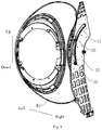
Fig. 5 is a schematic view showing that the track mechanism is mounted on a door unit according to an embodiment of the present invention from another angle. - Reference numerals:
supportingbody 10,guide portion 11,track body 20,track portion 21, connectingmember 30,door unit 40,movable portion 50. - Embodiments of the present invention will be described in detail in the following, and examples of the embodiments are shown in the drawings. The same or similar elements and the elements having same or similar functions are denoted by like reference numerals throughout the descriptions. The embodiments described hereafter with reference to drawings are explanatory, used to understand the present invention, and shall not be construed to limit the present invention.
- In the specification, unless specified or limited otherwise, relative terms such as "central", "thickness", "upper", "lower", "front", "rear", "left", "right", "vertical", "top", "bottom", "inner", "outer", "axial", "radial" and "circumferential" should be construed to refer to the orientation as then described or as shown in the drawings under discussion. These relative terms are for convenience of description and do not require that the present invention be constructed or operated in a particular orientation. Therefore, the above terms should not be construed to limit the present invention.
- A track mechanism A according to embodiments of the first aspect of the present invention is described hereafter with reference to
Fig. 1 to Fig. 3 . - As shown in
Fig. 1 to Fig. 3 , the track mechanism A according to the embodiments of the present invention includes a base. The base is provided with atrack portion 21 configured to guide a movable body (not shown in the drawings) to move along thetrack portion 21. The base includes a supportingbody 10 and atrack body 20, and thetrack portion 21 is arranged on thetrack body 20. The supportingbody 10 and thetrack body 20 are stacked and combined relative to each other, and the wear resistance of thetrack body 20 is higher than that of the supportingbody 10. - In the track mechanism A according to the embodiments of the present invention, the supporting
body 10 and thetrack body 20 are made of materials different in wear resistance, and then the base is assembled by them. Because the wear resistance of thetrack body 20 is higher than that of the supportingbody 10, the wear resistance of the base is improved. With the combined base, it is meant to give consideration to both performance requirement and manufacturing cost requirement, i.e. the desired performance requirement can be achieved with manufacturing cost reduced, which is beneficial to improvement of cost performance of the track mechanism A. - The supporting
body 10 is provided with aguide portion 11 corresponding to thetrack portion 21. That is, theguide portion 11 is in a shape matching that of thetrack portion 21 and in a position corresponding that of thetrack portion 21. Thetrack portion 21 and theguide portion 11 define arc grooves running through thetrack body 20 and the supportingbody 10 in the thickness direction respectively. Thus, thetrack portion 21 and theguide portion 11 cooperatively constitute a new arc groove with a large depth. - Optionally, a surface area of the
track body 20 is less than that of the supportingbody 10, and thetrack body 20 covers on a portion of the supportingbody 10 adjacent to theguide portion 11, thereby enhancing the structural strength and the wear resistance of the portion of the supportingbody 10 adjacent to theguide portion 11. - In some examples, the
track body 20 is made of high-strength wear-resistant material, while the supportingbody 10 may be made of high-strength low-cost material with good processability through low-cost process. Then thetrack body 20 is connected to the supportingbody 10. Since the wear resistance of thetrack body 20 is higher than that of the supportingbody 10, the supportingbody 10 is good in processability and low in manufacturing cost, such that the combined base has advantages of both. The fit between thetrack body 20 and amovable portion 50 is reliable, both the performance requirement and the manufacturing cost are taken in to account, and the cost performance of the track mechanism A are therefore improved. - According to an embodiment of the present invention, the movable body may be connected to one movable portion, and the movable portion moves along the
track portion 21. Thetrack portion 21 includes a plurality of tracks spaced apart from each other. Correspondingly, a plurality of movable portions are provided at positions corresponding to the plurality of tracks one to one. Supporting for the movable body provided by the base is improved, and the movable body can move along thetrack portion 21 more smoothly and reliably. - In some examples, the
track body 20 is provided with twotrack portions 21, and eachtrack portion 21 is embodied as an arc groove. The two arc grooves may be distributed and spaced along a circumferential direction of the same circumference, or may be distributed and spaced along a radial direction, which will be understood by one of ordinary skill in the art. - As shown in
Fig. 1 andFig. 2 , in some optional examples, the supportingbody 10 is detachably connected to thetrack body 20 by means of a connectingmember 30. For example, the connectingmember 30 may include a plurality of screws, and the plurality of screws are distributed and spaced along a circumferential direction of thetrack portion 21, which ensures that thetrack body 20 is reliably connected to the supportingbody 10, and the sides of thetrack body 20 and the supportingbody 10 opposite to each other are appressed, thereby improving the overall performance of the base. - As shown in
Fig. 3 , in some other optional examples, the supportingbody 10 is combined with thetrack body 20 by embedding or casting in a mold. For example, during manufacturing, thetrack body 20 and the supportingbody 10 are provided with profilings respectively, and shapes and positions of the profilings corresponds to each other. When thetrack body 20 is mounted to the supportingbody 10, a protruding profiling on thetrack body 20 is pressed into a groove profiling in the supportingbody 10 to achieve stable connection therebetween, the operation is easy and the reliability of connection is high. - A front-loading washing machine (not shown in the drawings) according to embodiments of the second aspect of the present invention is described hereafter with reference to
Fig. 1 to Fig. 5 . It should be noted that, in the present invention, the front-loading washing machine may refer to a clothes treatment device capable of washing clothes, such as a washing machine or a front-loading washer-dryer. - The front-loading washing machine according to the embodiments the present invention includes a cabinet (not shown in the drawings), a tub (not shown in the drawings), a rotatable drum (not shown in the drawings), a
door unit 40 and the track mechanism A according to the above embodiments. - The cabinet includes a front panel, and the front panel defines an opening. The tub defines an access port. The tub is arranged in the cabinet and configured to make the access port move upwards and downwards in the opening. The rotatable drum is arranged in the tub. The
door unit 40 is mounted to the tub and covers on the access port. - The
door unit 40 is configured as the movable body. During operation, thedoor unit 40 can swing in a vertical plane along with the tub, at the same time, thedoor unit 40 moves upwards and downwards in the opening under guide of the track mechanism A. - The front-loading washing machine according to the embodiments the present invention adopts the track mechanism A including the base combined of the supporting
body 10 and thetrack body 20, both the performance requirement and the manufacturing cost are taken in to account, and the cost performance of the front-loading washing machine can be improved on the premise that the front-loading washing machine can be reliably used. - As shown in
Fig. 4 andFig. 5 , according to an embodiment of the present invention, the front-loading washing machine further includes themovable portion 50, and themovable portion 50 is configured to move along thetrack portion 21. Thedoor unit 40 is connected to themovable portion 50 by means of a connecting part (not shown in the drawings). The tub drives thedoor unit 40 to swing when swinging in the vertical plane, while at the same time, themovable portion 50 on thedoor unit 40 moves long thetrack portion 21 of the track mechanism A. - In some examples, the track mechanism A is arranged at one side of the door unit 40 (a right side of the
door unit 40 shown inFig. 4 andFig. 5 ). Thetrack body 20 is located at a side of the supportingbody 10 facing the door unit 40 (a left side of the supportingbody 10 shown inFig. 5 ). The track mechanism A is connected to thedoor unit 40 by means of fit between themovable portion 50 and thetrack portion 21. The structure is simple and compact, and the connection is reliable. - The
track portion 21 may be an arc groove extending along a circumferential direction of a swinging center of the tub. During movement of thedoor unit 40, themovable portion 50 on thedoor unit 40 always slides along thetrack portion 21. The fit between thetrack portion 21 and themovable portion 50 can used for limiting and further supporting thedoor unit 40, which improves stability of the structure during operation and use reliability. - In some examples, the
movable portion 50 includes a body and a moving end which is rotatable relative to the body. The body is connected to thedoor unit 40 by means of a connecting part. In some specific examples, the moving end may be fitted over the body and is spaced apart from the body in a radial direction. A rolling body is arranged between the moving end and the body, and the rolling body is a ball. The moving end is configured to be embedded in thetrack portion 21 and can rotate along with thetrack portion 21. When the tub swings, the body of themovable portion 50 is stationary relative to thedoor unit 40, and the moving end rotates relative to the body. The movement is stable and reliable. - In some optional examples, the moving end defines a recess in a portion in contact with the
track portion 21, and the recess is fitted with thetrack portion 21. That is, the moving body of themovable portion 50 may be annular member, the annular member extends along a thickness direction of the base, and two ends of the annular member have sizes larger than that of a middle portion of the annular member. Therefore, themovable portion 50 straddles on the base, such that the recess in the middle portion of the moving end is fitted with an inner wall of the arc groove, which can prevent themovable portion 50 from falling off the base, and further ensures that the fit between themovable portion 50 and the base is reliable. - Of course, the
movable portion 50 of the front-loading washing machine is not limited by this, for example, themovable portion 50 may be a pulley straddles on the base, and a shaft of the pulley is connected to thedoor unit 40 by means of the connecting part. - According to some embodiments of the present invention, two track mechanisms A are provided, and the two track mechanisms A are symmetrically arranged at two sides of the cabinet respectively. Specifically, the two track mechanisms A are arranged at a left side and a right side of the
door unit 40 respectively, one the track mechanism A is opposite to an inner wall of a left side wall of the cabinet, and the other track mechanism A is opposite to an inner wall of a right side wall of the cabinet. When the tub swings, thedoor unit 40 moves under guide of the two track mechanisms A, and the structure is stable and reliable. - The front-loading washing machine according to the embodiments the present invention is simple and compact in structure, high in use reliability and cost performance, and both the performance requirement and the manufacturing cost are taken in to account.
- Other configurations and operations of the front-loading washing machine according to embodiments the present invention are known to one of ordinary skill in the art, and will not be described in detail herein.
- Reference throughout this specification to "an embodiment," "some embodiments," "exemplary embodiment", "an example," "a specific example," or "some examples," means that a particular feature, structure, material, or characteristic described in connection with the embodiment or example is included in at least one embodiment or example of the present invention. Thus, the appearances of the phrases throughout this specification are not necessarily referring to the same embodiment or example of the present invention. Furthermore, the particular features, structures, materials, or characteristics may be combined in any suitable manner in one or more embodiments or examples.
- Although explanatory embodiments have been shown and described, it would be appreciated by those skilled in the art that changes, modifications, alternatives, and variations can be made in the above embodiments without departing from principles and purposes of the present invention, and the scope of the present invention is defined by the claims.
Claims (12)
- A track mechanism for a door unit of a front-loading washing machine comprising a base, the base being provided with a track portion (21) configured to guide a movable body to move along the track portion (21), wherein the base comprises a supporting body (10) and a track body (20), the track portion (21) is arranged on the track body (20), the supporting body (10) and the track body (20) are stacked and combined relative to each other, the supporting body (10) is provided with a guide portion (11) in a corresponding shape and position to the track portion (21), and wear resistance of the track body (20) is higher than that of the supporting body (10).
- The track mechanism according to claim 1, wherein the track portion (21) comprises a plurality of tracks spaced apart from each other.
- The track mechanism according to claim 1 or 2, wherein the supporting body (10) is combined with the track body (20) by means of a connecting member (30).
- The track mechanism according to claim 3, wherein the connecting member (30) is a screw.
- The track mechanism according to claim 1 or 2, wherein the supporting body (10) is combined with the track body (20) by embedding or casting in a mold.
- The track mechanism according to any one of claims 1 to 5, wherein the track portion (21) is an arc groove.
- A front-loading washing machine, comprising:a cabinet comprising a front panel, the front panel defining an opening;a tub defining an access port, arranged in the cabinet and configured to make the access port move upwards and downwards in the opening;a rotatable drum arranged in the tub;a door unit (40) mounted to the tub and covering the access port; anda track mechanism according to any one of claims 1 to 6, wherein the movable body is the door unit (40) and the door unit (40) moves upwards and downwards in the opening under guide of the track mechanism.
- The front-loading washing machine according to claim 7, further comprising a movable portion (50), the movable portion (50) is configured to move along the track portion (21), and the door unit (40) is connected to the movable portion (50) by means of a connecting part.
- The front-loading washing machine according to claim 8, wherein the movable portion (50) includes a body and a moving end rotatable relative to the body, the moving end and the body are provided with a rolling body therebetween, and the moving end is configured to be embedded in the track portion (21) and can rotate along the track portion (21).
- The front-loading washing machine according to claim 9, wherein the rolling body is a ball.
- The front-loading washing machine according to claim 9 or 10, wherein the moving end defines a recess in a portion in contact with the track portion (21), and the recess is fitted with the track portion (21).
- The front-loading washing machine according to any one of claims 7 to 11, wherein two track mechanisms are symmetrically provided at two sides of the cabinet respectively.
Applications Claiming Priority (2)
| Application Number | Priority Date | Filing Date | Title |
|---|---|---|---|
| CN201710199173.4A CN107044037B (en) | 2017-03-29 | 2017-03-29 | Rail mechanism and roller washing machine with it |
| PCT/CN2017/102325 WO2018176748A1 (en) | 2017-03-29 | 2017-09-19 | Track mechanism and front-loader washing machine having same |
Publications (3)
| Publication Number | Publication Date |
|---|---|
| EP3604659A1 EP3604659A1 (en) | 2020-02-05 |
| EP3604659A4 EP3604659A4 (en) | 2020-02-05 |
| EP3604659B1 true EP3604659B1 (en) | 2021-04-14 |
Family
ID=59545556
Family Applications (1)
| Application Number | Title | Priority Date | Filing Date |
|---|---|---|---|
| EP17903463.2A Active EP3604659B1 (en) | 2017-03-29 | 2017-09-19 | Track mechanism and front-loader washing machine having same |
Country Status (5)
| Country | Link |
|---|---|
| US (1) | US11585033B2 (en) |
| EP (1) | EP3604659B1 (en) |
| JP (1) | JP6845326B2 (en) |
| CN (1) | CN107044037B (en) |
| WO (1) | WO2018176748A1 (en) |
Families Citing this family (2)
| Publication number | Priority date | Publication date | Assignee | Title |
|---|---|---|---|---|
| US11377772B2 (en) | 2019-05-23 | 2022-07-05 | Whirlpool Corporation | Laundry appliance |
| US11761134B2 (en) | 2019-05-23 | 2023-09-19 | Whirlpool Corporation | Laundry appliance |
Family Cites Families (29)
| Publication number | Priority date | Publication date | Assignee | Title |
|---|---|---|---|---|
| US2639601A (en) * | 1949-12-15 | 1953-05-26 | Miller Herman | Swingable door for tumbler type clothes washing machines |
| GB1077847A (en) * | 1964-12-18 | 1967-08-02 | James Armstrong & Co Ltd | Washing machines and control systems therefor |
| US3521319A (en) * | 1968-02-12 | 1970-07-21 | Illinois Tool Works | Door positioner |
| US3498089A (en) * | 1968-06-28 | 1970-03-03 | Mc Graw Edison Co | Laundry machine |
| US6233980B1 (en) * | 1999-06-23 | 2001-05-22 | Andrew F. Kegler | Dry cleaning vessel door opening apparatus with self-aligning and reduced stress locking lugs |
| JP2002069904A (en) * | 2000-09-01 | 2002-03-08 | Mitsubishi Heavy Ind Ltd | Structure and method for paving curved part of monorail girder |
| US6786144B2 (en) * | 2001-05-30 | 2004-09-07 | New Gencoat, Inc. | Wringer roller system |
| ATE323751T1 (en) * | 2001-09-25 | 2006-05-15 | Fuji Photo Film Co Ltd | COMPOUND CONTAINING A HETEROCYCLIC RING AND A LUBRICANT MIXTURE CONTAINING SAME |
| JP4068425B2 (en) * | 2002-09-26 | 2008-03-26 | Necフィールディング株式会社 | Drum washing machine |
| JP2005262358A (en) * | 2004-03-17 | 2005-09-29 | Shinkawa Ltd | Linear motion table |
| CN2729088Y (en) * | 2004-09-28 | 2005-09-28 | 钱仲尧 | Improved slide for metallurgical heating furnace |
| KR100673446B1 (en) * | 2004-10-25 | 2007-01-24 | 엘지전자 주식회사 | Laundry treatment unit with folding door |
| ATE470745T1 (en) * | 2007-02-23 | 2010-06-15 | Electrolux Home Prod Corp | ELECTRICAL DEVICE WITH IMPROVED TOWER MECHANISM |
| US20080295546A1 (en) * | 2007-05-28 | 2008-12-04 | Cheon-Soo Cho | Top-loading type washing machine |
| CN101581528B (en) * | 2008-05-16 | 2013-04-03 | 海尔集团公司 | Slide mechanism of drawer |
| KR101604688B1 (en) * | 2009-05-04 | 2016-03-18 | 엘지전자 주식회사 | Laundry machine |
| KR20110057920A (en) * | 2009-11-25 | 2011-06-01 | 삼성전자주식회사 | Drum washing machine |
| KR20110083833A (en) * | 2010-01-15 | 2011-07-21 | 삼성전자주식회사 | Washing machine |
| JP5682373B2 (en) * | 2011-02-25 | 2015-03-11 | 日本精工株式会社 | Curve motion device, optical measurement device, X-ray device, and machine tool |
| EP2330247B1 (en) | 2011-03-08 | 2013-03-27 | V-Zug AG | Washer-dryer, in particular cabinet dryer |
| DE102013013956B4 (en) * | 2013-08-21 | 2024-07-04 | Andreas Stihl Ag & Co. Kg | Guide bar for a saw chain with a wear-reduced deflection section |
| CN203923814U (en) * | 2013-12-29 | 2014-11-05 | 河南省大地水泥有限公司 | A kind of reclaimer walking track |
| CN203939363U (en) * | 2014-05-22 | 2014-11-12 | 梁锐金 | A kind of novel stainless steel guide rail |
| CN104313830B (en) * | 2014-10-20 | 2016-08-31 | 成都快典科技有限公司 | A kind of light washing machine and using method thereof |
| DE102014226318A1 (en) * | 2014-12-17 | 2016-06-23 | Raventech GmbH | Washing machine and method for operating a washing machine |
| KR102426183B1 (en) * | 2015-06-05 | 2022-07-29 | 엘지전자 주식회사 | Refrigerator |
| CN105603834A (en) * | 2016-01-15 | 2016-05-25 | 西南交通大学 | Suspension type monorail track and trolley bus |
| CN105795871A (en) * | 2016-04-29 | 2016-07-27 | 唐海军 | Multi-pulley combined type electric curtain track |
| US10221515B2 (en) * | 2016-09-13 | 2019-03-05 | Whirlpool Corporation | Laundry treating appliance and dispenser |
-
2017
- 2017-03-29 CN CN201710199173.4A patent/CN107044037B/en active Active
- 2017-09-19 JP JP2019529626A patent/JP6845326B2/en active Active
- 2017-09-19 EP EP17903463.2A patent/EP3604659B1/en active Active
- 2017-09-19 WO PCT/CN2017/102325 patent/WO2018176748A1/en not_active Ceased
-
2019
- 2019-09-20 US US16/578,151 patent/US11585033B2/en active Active
Non-Patent Citations (1)
| Title |
|---|
| None * |
Also Published As
| Publication number | Publication date |
|---|---|
| JP2020508416A (en) | 2020-03-19 |
| EP3604659A1 (en) | 2020-02-05 |
| EP3604659A4 (en) | 2020-02-05 |
| US11585033B2 (en) | 2023-02-21 |
| US20200010996A1 (en) | 2020-01-09 |
| CN107044037A (en) | 2017-08-15 |
| CN107044037B (en) | 2019-07-19 |
| JP6845326B2 (en) | 2021-03-17 |
| WO2018176748A1 (en) | 2018-10-04 |
Similar Documents
| Publication | Publication Date | Title |
|---|---|---|
| US20120180532A1 (en) | Washing machine and pulsator thereof | |
| US9598811B2 (en) | Washing machine | |
| CN112048876B (en) | A pulsator washing machine | |
| EP2557215B1 (en) | Washing machine | |
| US11585033B2 (en) | Track mechanism and front-loading washing machine with same | |
| CN107558118B (en) | washing machine | |
| US9464374B2 (en) | Pulsator device usable with washing machine and washing machine having the same | |
| KR20230155393A (en) | Washing Machine | |
| KR102624051B1 (en) | Door hinge with two-stage force | |
| US20170218550A1 (en) | Front-loading washing machine | |
| CN111492102A (en) | Washing machine | |
| US20150121968A1 (en) | Balancer and washing machine having the same | |
| US20120104129A1 (en) | Food waste disposal apparatus | |
| JP6789313B2 (en) | Safety control structure for opening and closing the top lid | |
| CN108691151A (en) | A kind of control panel and washing machine of washing machine | |
| CN107653646B (en) | Workbench assembly of washing machine and washing machine with workbench assembly | |
| CN109208275B (en) | Clothes treatment device | |
| CN107012644B (en) | Movable drum washing machine with clothes taking and putting opening | |
| CN107142675B (en) | washing machine | |
| CN222530295U (en) | Wall switch | |
| CN108330650B (en) | Detergent box and washing machine | |
| CN111979721A (en) | A clothing treatment device | |
| CN219280291U (en) | Lifting rib, roller assembly and clothes treatment equipment | |
| CN111485780B (en) | Hinge assembly and appliance provided with same | |
| WO2016193369A1 (en) | Household appliance with adjustable height controlled from the front |
Legal Events
| Date | Code | Title | Description |
|---|---|---|---|
| STAA | Information on the status of an ep patent application or granted ep patent |
Free format text: STATUS: THE INTERNATIONAL PUBLICATION HAS BEEN MADE |
|
| PUAI | Public reference made under article 153(3) epc to a published international application that has entered the european phase |
Free format text: ORIGINAL CODE: 0009012 |
|
| STAA | Information on the status of an ep patent application or granted ep patent |
Free format text: STATUS: REQUEST FOR EXAMINATION WAS MADE |
|
| 17P | Request for examination filed |
Effective date: 20191023 |
|
| A4 | Supplementary search report drawn up and despatched |
Effective date: 20191213 |
|
| AK | Designated contracting states |
Kind code of ref document: A1 Designated state(s): AL AT BE BG CH CY CZ DE DK EE ES FI FR GB GR HR HU IE IS IT LI LT LU LV MC MK MT NL NO PL PT RO RS SE SI SK SM TR |
|
| AX | Request for extension of the european patent |
Extension state: BA ME |
|
| DAV | Request for validation of the european patent (deleted) | ||
| DAX | Request for extension of the european patent (deleted) | ||
| GRAP | Despatch of communication of intention to grant a patent |
Free format text: ORIGINAL CODE: EPIDOSNIGR1 |
|
| STAA | Information on the status of an ep patent application or granted ep patent |
Free format text: STATUS: GRANT OF PATENT IS INTENDED |
|
| INTG | Intention to grant announced |
Effective date: 20210125 |
|
| GRAS | Grant fee paid |
Free format text: ORIGINAL CODE: EPIDOSNIGR3 |
|
| GRAA | (expected) grant |
Free format text: ORIGINAL CODE: 0009210 |
|
| STAA | Information on the status of an ep patent application or granted ep patent |
Free format text: STATUS: THE PATENT HAS BEEN GRANTED |
|
| AK | Designated contracting states |
Kind code of ref document: B1 Designated state(s): AL AT BE BG CH CY CZ DE DK EE ES FI FR GB GR HR HU IE IS IT LI LT LU LV MC MK MT NL NO PL PT RO RS SE SI SK SM TR |
|
| REG | Reference to a national code |
Ref country code: GB Ref legal event code: FG4D |
|
| REG | Reference to a national code |
Ref country code: CH Ref legal event code: EP |
|
| REG | Reference to a national code |
Ref country code: DE Ref legal event code: R096 Ref document number: 602017036922 Country of ref document: DE |
|
| REG | Reference to a national code |
Ref country code: IE Ref legal event code: FG4D |
|
| REG | Reference to a national code |
Ref country code: AT Ref legal event code: REF Ref document number: 1382477 Country of ref document: AT Kind code of ref document: T Effective date: 20210515 |
|
| REG | Reference to a national code |
Ref country code: LT Ref legal event code: MG9D |
|
| REG | Reference to a national code |
Ref country code: AT Ref legal event code: MK05 Ref document number: 1382477 Country of ref document: AT Kind code of ref document: T Effective date: 20210414 |
|
| REG | Reference to a national code |
Ref country code: NL Ref legal event code: MP Effective date: 20210414 |
|
| PG25 | Lapsed in a contracting state [announced via postgrant information from national office to epo] |
Ref country code: NL Free format text: LAPSE BECAUSE OF FAILURE TO SUBMIT A TRANSLATION OF THE DESCRIPTION OR TO PAY THE FEE WITHIN THE PRESCRIBED TIME-LIMIT Effective date: 20210414 Ref country code: AT Free format text: LAPSE BECAUSE OF FAILURE TO SUBMIT A TRANSLATION OF THE DESCRIPTION OR TO PAY THE FEE WITHIN THE PRESCRIBED TIME-LIMIT Effective date: 20210414 Ref country code: BG Free format text: LAPSE BECAUSE OF FAILURE TO SUBMIT A TRANSLATION OF THE DESCRIPTION OR TO PAY THE FEE WITHIN THE PRESCRIBED TIME-LIMIT Effective date: 20210714 Ref country code: HR Free format text: LAPSE BECAUSE OF FAILURE TO SUBMIT A TRANSLATION OF THE DESCRIPTION OR TO PAY THE FEE WITHIN THE PRESCRIBED TIME-LIMIT Effective date: 20210414 Ref country code: FI Free format text: LAPSE BECAUSE OF FAILURE TO SUBMIT A TRANSLATION OF THE DESCRIPTION OR TO PAY THE FEE WITHIN THE PRESCRIBED TIME-LIMIT Effective date: 20210414 Ref country code: LT Free format text: LAPSE BECAUSE OF FAILURE TO SUBMIT A TRANSLATION OF THE DESCRIPTION OR TO PAY THE FEE WITHIN THE PRESCRIBED TIME-LIMIT Effective date: 20210414 |
|
| PG25 | Lapsed in a contracting state [announced via postgrant information from national office to epo] |
Ref country code: PL Free format text: LAPSE BECAUSE OF FAILURE TO SUBMIT A TRANSLATION OF THE DESCRIPTION OR TO PAY THE FEE WITHIN THE PRESCRIBED TIME-LIMIT Effective date: 20210414 Ref country code: NO Free format text: LAPSE BECAUSE OF FAILURE TO SUBMIT A TRANSLATION OF THE DESCRIPTION OR TO PAY THE FEE WITHIN THE PRESCRIBED TIME-LIMIT Effective date: 20210714 Ref country code: PT Free format text: LAPSE BECAUSE OF FAILURE TO SUBMIT A TRANSLATION OF THE DESCRIPTION OR TO PAY THE FEE WITHIN THE PRESCRIBED TIME-LIMIT Effective date: 20210816 Ref country code: LV Free format text: LAPSE BECAUSE OF FAILURE TO SUBMIT A TRANSLATION OF THE DESCRIPTION OR TO PAY THE FEE WITHIN THE PRESCRIBED TIME-LIMIT Effective date: 20210414 Ref country code: RS Free format text: LAPSE BECAUSE OF FAILURE TO SUBMIT A TRANSLATION OF THE DESCRIPTION OR TO PAY THE FEE WITHIN THE PRESCRIBED TIME-LIMIT Effective date: 20210414 Ref country code: SE Free format text: LAPSE BECAUSE OF FAILURE TO SUBMIT A TRANSLATION OF THE DESCRIPTION OR TO PAY THE FEE WITHIN THE PRESCRIBED TIME-LIMIT Effective date: 20210414 Ref country code: IS Free format text: LAPSE BECAUSE OF FAILURE TO SUBMIT A TRANSLATION OF THE DESCRIPTION OR TO PAY THE FEE WITHIN THE PRESCRIBED TIME-LIMIT Effective date: 20210814 Ref country code: GR Free format text: LAPSE BECAUSE OF FAILURE TO SUBMIT A TRANSLATION OF THE DESCRIPTION OR TO PAY THE FEE WITHIN THE PRESCRIBED TIME-LIMIT Effective date: 20210715 |
|
| REG | Reference to a national code |
Ref country code: DE Ref legal event code: R097 Ref document number: 602017036922 Country of ref document: DE |
|
| PG25 | Lapsed in a contracting state [announced via postgrant information from national office to epo] |
Ref country code: SK Free format text: LAPSE BECAUSE OF FAILURE TO SUBMIT A TRANSLATION OF THE DESCRIPTION OR TO PAY THE FEE WITHIN THE PRESCRIBED TIME-LIMIT Effective date: 20210414 Ref country code: SM Free format text: LAPSE BECAUSE OF FAILURE TO SUBMIT A TRANSLATION OF THE DESCRIPTION OR TO PAY THE FEE WITHIN THE PRESCRIBED TIME-LIMIT Effective date: 20210414 Ref country code: ES Free format text: LAPSE BECAUSE OF FAILURE TO SUBMIT A TRANSLATION OF THE DESCRIPTION OR TO PAY THE FEE WITHIN THE PRESCRIBED TIME-LIMIT Effective date: 20210414 Ref country code: EE Free format text: LAPSE BECAUSE OF FAILURE TO SUBMIT A TRANSLATION OF THE DESCRIPTION OR TO PAY THE FEE WITHIN THE PRESCRIBED TIME-LIMIT Effective date: 20210414 Ref country code: RO Free format text: LAPSE BECAUSE OF FAILURE TO SUBMIT A TRANSLATION OF THE DESCRIPTION OR TO PAY THE FEE WITHIN THE PRESCRIBED TIME-LIMIT Effective date: 20210414 Ref country code: DK Free format text: LAPSE BECAUSE OF FAILURE TO SUBMIT A TRANSLATION OF THE DESCRIPTION OR TO PAY THE FEE WITHIN THE PRESCRIBED TIME-LIMIT Effective date: 20210414 Ref country code: CZ Free format text: LAPSE BECAUSE OF FAILURE TO SUBMIT A TRANSLATION OF THE DESCRIPTION OR TO PAY THE FEE WITHIN THE PRESCRIBED TIME-LIMIT Effective date: 20210414 |
|
| PLBE | No opposition filed within time limit |
Free format text: ORIGINAL CODE: 0009261 |
|
| STAA | Information on the status of an ep patent application or granted ep patent |
Free format text: STATUS: NO OPPOSITION FILED WITHIN TIME LIMIT |
|
| 26N | No opposition filed |
Effective date: 20220117 |
|
| REG | Reference to a national code |
Ref country code: CH Ref legal event code: PL |
|
| REG | Reference to a national code |
Ref country code: BE Ref legal event code: MM Effective date: 20210930 |
|
| GBPC | Gb: european patent ceased through non-payment of renewal fee |
Effective date: 20210919 |
|
| PG25 | Lapsed in a contracting state [announced via postgrant information from national office to epo] |
Ref country code: IS Free format text: LAPSE BECAUSE OF FAILURE TO SUBMIT A TRANSLATION OF THE DESCRIPTION OR TO PAY THE FEE WITHIN THE PRESCRIBED TIME-LIMIT Effective date: 20210814 Ref country code: MC Free format text: LAPSE BECAUSE OF FAILURE TO SUBMIT A TRANSLATION OF THE DESCRIPTION OR TO PAY THE FEE WITHIN THE PRESCRIBED TIME-LIMIT Effective date: 20210414 Ref country code: AL Free format text: LAPSE BECAUSE OF FAILURE TO SUBMIT A TRANSLATION OF THE DESCRIPTION OR TO PAY THE FEE WITHIN THE PRESCRIBED TIME-LIMIT Effective date: 20210414 |
|
| PG25 | Lapsed in a contracting state [announced via postgrant information from national office to epo] |
Ref country code: LU Free format text: LAPSE BECAUSE OF NON-PAYMENT OF DUE FEES Effective date: 20210919 Ref country code: IT Free format text: LAPSE BECAUSE OF FAILURE TO SUBMIT A TRANSLATION OF THE DESCRIPTION OR TO PAY THE FEE WITHIN THE PRESCRIBED TIME-LIMIT Effective date: 20210414 Ref country code: IE Free format text: LAPSE BECAUSE OF NON-PAYMENT OF DUE FEES Effective date: 20210919 Ref country code: GB Free format text: LAPSE BECAUSE OF NON-PAYMENT OF DUE FEES Effective date: 20210919 Ref country code: FR Free format text: LAPSE BECAUSE OF NON-PAYMENT OF DUE FEES Effective date: 20210930 Ref country code: BE Free format text: LAPSE BECAUSE OF NON-PAYMENT OF DUE FEES Effective date: 20210930 |
|
| PG25 | Lapsed in a contracting state [announced via postgrant information from national office to epo] |
Ref country code: LI Free format text: LAPSE BECAUSE OF NON-PAYMENT OF DUE FEES Effective date: 20210930 Ref country code: CH Free format text: LAPSE BECAUSE OF NON-PAYMENT OF DUE FEES Effective date: 20210930 |
|
| PG25 | Lapsed in a contracting state [announced via postgrant information from national office to epo] |
Ref country code: CY Free format text: LAPSE BECAUSE OF FAILURE TO SUBMIT A TRANSLATION OF THE DESCRIPTION OR TO PAY THE FEE WITHIN THE PRESCRIBED TIME-LIMIT Effective date: 20210414 |
|
| PG25 | Lapsed in a contracting state [announced via postgrant information from national office to epo] |
Ref country code: HU Free format text: LAPSE BECAUSE OF FAILURE TO SUBMIT A TRANSLATION OF THE DESCRIPTION OR TO PAY THE FEE WITHIN THE PRESCRIBED TIME-LIMIT; INVALID AB INITIO Effective date: 20170919 |
|
| PG25 | Lapsed in a contracting state [announced via postgrant information from national office to epo] |
Ref country code: MK Free format text: LAPSE BECAUSE OF FAILURE TO SUBMIT A TRANSLATION OF THE DESCRIPTION OR TO PAY THE FEE WITHIN THE PRESCRIBED TIME-LIMIT Effective date: 20210414 |
|
| PG25 | Lapsed in a contracting state [announced via postgrant information from national office to epo] |
Ref country code: TR Free format text: LAPSE BECAUSE OF FAILURE TO SUBMIT A TRANSLATION OF THE DESCRIPTION OR TO PAY THE FEE WITHIN THE PRESCRIBED TIME-LIMIT Effective date: 20210414 |
|
| PG25 | Lapsed in a contracting state [announced via postgrant information from national office to epo] |
Ref country code: MT Free format text: LAPSE BECAUSE OF FAILURE TO SUBMIT A TRANSLATION OF THE DESCRIPTION OR TO PAY THE FEE WITHIN THE PRESCRIBED TIME-LIMIT Effective date: 20210414 |
|
| PGFP | Annual fee paid to national office [announced via postgrant information from national office to epo] |
Ref country code: DE Payment date: 20250923 Year of fee payment: 9 |