EP3604563A1 - Method for producing rail - Google Patents
Method for producing rail Download PDFInfo
- Publication number
- EP3604563A1 EP3604563A1 EP18772424.0A EP18772424A EP3604563A1 EP 3604563 A1 EP3604563 A1 EP 3604563A1 EP 18772424 A EP18772424 A EP 18772424A EP 3604563 A1 EP3604563 A1 EP 3604563A1
- Authority
- EP
- European Patent Office
- Prior art keywords
- rail
- less
- proof stress
- straightening
- content
- Prior art date
- Legal status (The legal status is an assumption and is not a legal conclusion. Google has not performed a legal analysis and makes no representation as to the accuracy of the status listed.)
- Granted
Links
Images

Classifications
-
- C—CHEMISTRY; METALLURGY
- C21—METALLURGY OF IRON
- C21D—MODIFYING THE PHYSICAL STRUCTURE OF FERROUS METALS; GENERAL DEVICES FOR HEAT TREATMENT OF FERROUS OR NON-FERROUS METALS OR ALLOYS; MAKING METAL MALLEABLE, e.g. BY DECARBURISATION OR TEMPERING
- C21D9/00—Heat treatment, e.g. annealing, hardening, quenching or tempering, adapted for particular articles; Furnaces therefor
- C21D9/04—Heat treatment, e.g. annealing, hardening, quenching or tempering, adapted for particular articles; Furnaces therefor for rails
-
- C—CHEMISTRY; METALLURGY
- C21—METALLURGY OF IRON
- C21D—MODIFYING THE PHYSICAL STRUCTURE OF FERROUS METALS; GENERAL DEVICES FOR HEAT TREATMENT OF FERROUS OR NON-FERROUS METALS OR ALLOYS; MAKING METAL MALLEABLE, e.g. BY DECARBURISATION OR TEMPERING
- C21D6/00—Heat treatment of ferrous alloys
- C21D6/002—Heat treatment of ferrous alloys containing Cr
-
- C—CHEMISTRY; METALLURGY
- C21—METALLURGY OF IRON
- C21D—MODIFYING THE PHYSICAL STRUCTURE OF FERROUS METALS; GENERAL DEVICES FOR HEAT TREATMENT OF FERROUS OR NON-FERROUS METALS OR ALLOYS; MAKING METAL MALLEABLE, e.g. BY DECARBURISATION OR TEMPERING
- C21D6/00—Heat treatment of ferrous alloys
- C21D6/005—Heat treatment of ferrous alloys containing Mn
-
- C—CHEMISTRY; METALLURGY
- C21—METALLURGY OF IRON
- C21D—MODIFYING THE PHYSICAL STRUCTURE OF FERROUS METALS; GENERAL DEVICES FOR HEAT TREATMENT OF FERROUS OR NON-FERROUS METALS OR ALLOYS; MAKING METAL MALLEABLE, e.g. BY DECARBURISATION OR TEMPERING
- C21D6/00—Heat treatment of ferrous alloys
- C21D6/008—Heat treatment of ferrous alloys containing Si
-
- C—CHEMISTRY; METALLURGY
- C21—METALLURGY OF IRON
- C21D—MODIFYING THE PHYSICAL STRUCTURE OF FERROUS METALS; GENERAL DEVICES FOR HEAT TREATMENT OF FERROUS OR NON-FERROUS METALS OR ALLOYS; MAKING METAL MALLEABLE, e.g. BY DECARBURISATION OR TEMPERING
- C21D8/00—Modifying the physical properties of ferrous metals or ferrous alloys by deformation combined with, or followed by, heat treatment
-
- C—CHEMISTRY; METALLURGY
- C22—METALLURGY; FERROUS OR NON-FERROUS ALLOYS; TREATMENT OF ALLOYS OR NON-FERROUS METALS
- C22C—ALLOYS
- C22C38/00—Ferrous alloys, e.g. steel alloys
- C22C38/002—Ferrous alloys, e.g. steel alloys containing In, Mg, or other elements not provided for in one single group C22C38/001 - C22C38/60
-
- C—CHEMISTRY; METALLURGY
- C22—METALLURGY; FERROUS OR NON-FERROUS ALLOYS; TREATMENT OF ALLOYS OR NON-FERROUS METALS
- C22C—ALLOYS
- C22C38/00—Ferrous alloys, e.g. steel alloys
- C22C38/02—Ferrous alloys, e.g. steel alloys containing silicon
-
- C—CHEMISTRY; METALLURGY
- C22—METALLURGY; FERROUS OR NON-FERROUS ALLOYS; TREATMENT OF ALLOYS OR NON-FERROUS METALS
- C22C—ALLOYS
- C22C38/00—Ferrous alloys, e.g. steel alloys
- C22C38/04—Ferrous alloys, e.g. steel alloys containing manganese
-
- C—CHEMISTRY; METALLURGY
- C22—METALLURGY; FERROUS OR NON-FERROUS ALLOYS; TREATMENT OF ALLOYS OR NON-FERROUS METALS
- C22C—ALLOYS
- C22C38/00—Ferrous alloys, e.g. steel alloys
- C22C38/18—Ferrous alloys, e.g. steel alloys containing chromium
- C22C38/22—Ferrous alloys, e.g. steel alloys containing chromium with molybdenum or tungsten
-
- C—CHEMISTRY; METALLURGY
- C22—METALLURGY; FERROUS OR NON-FERROUS ALLOYS; TREATMENT OF ALLOYS OR NON-FERROUS METALS
- C22C—ALLOYS
- C22C38/00—Ferrous alloys, e.g. steel alloys
- C22C38/18—Ferrous alloys, e.g. steel alloys containing chromium
- C22C38/24—Ferrous alloys, e.g. steel alloys containing chromium with vanadium
-
- C—CHEMISTRY; METALLURGY
- C22—METALLURGY; FERROUS OR NON-FERROUS ALLOYS; TREATMENT OF ALLOYS OR NON-FERROUS METALS
- C22C—ALLOYS
- C22C38/00—Ferrous alloys, e.g. steel alloys
- C22C38/18—Ferrous alloys, e.g. steel alloys containing chromium
- C22C38/26—Ferrous alloys, e.g. steel alloys containing chromium with niobium or tantalum
-
- C—CHEMISTRY; METALLURGY
- C22—METALLURGY; FERROUS OR NON-FERROUS ALLOYS; TREATMENT OF ALLOYS OR NON-FERROUS METALS
- C22C—ALLOYS
- C22C38/00—Ferrous alloys, e.g. steel alloys
- C22C38/18—Ferrous alloys, e.g. steel alloys containing chromium
- C22C38/28—Ferrous alloys, e.g. steel alloys containing chromium with titanium or zirconium
-
- C—CHEMISTRY; METALLURGY
- C22—METALLURGY; FERROUS OR NON-FERROUS ALLOYS; TREATMENT OF ALLOYS OR NON-FERROUS METALS
- C22C—ALLOYS
- C22C38/00—Ferrous alloys, e.g. steel alloys
- C22C38/18—Ferrous alloys, e.g. steel alloys containing chromium
- C22C38/32—Ferrous alloys, e.g. steel alloys containing chromium with boron
-
- C—CHEMISTRY; METALLURGY
- C22—METALLURGY; FERROUS OR NON-FERROUS ALLOYS; TREATMENT OF ALLOYS OR NON-FERROUS METALS
- C22C—ALLOYS
- C22C38/00—Ferrous alloys, e.g. steel alloys
- C22C38/18—Ferrous alloys, e.g. steel alloys containing chromium
- C22C38/40—Ferrous alloys, e.g. steel alloys containing chromium with nickel
- C22C38/42—Ferrous alloys, e.g. steel alloys containing chromium with nickel with copper
Definitions
- the disclosure relates to method for producing a rail, in particular a high-strength pearlitic rail. Specifically, because this kind of rail is used under severe high axle load conditions such as in mining railways which are weighted with heavy freight cars and often have steep curves, the disclosure provides a method for providing a high-strength pearlitic rail having excellent rolling contact fatigue resistance which is suitable for prolonging the rail service life.
- JP 5292875 B proposes a rail having excellent wear resistance, rolling contact fatigue resistance, and delayed fracture resistance, the rail having defined ratios of the Mn content and the Cr content, and of the V content and the N content.
- JP 5493950 B proposes a method for producing a pearlitic rail having excellent wear resistance and ductility, in which the pearlitic rail has defined contents of C and Cu and is subjected to post heat treatment at heating temperature of 450 °C to 550 °C for 0.5 h to 24 h.
- JP 2000-219939 A proposes a pearlitic rail having excellent wear resistance and surface damage resistance, the pearlitic rail having a defined C content and structure and further having a 0.2 % proof stress of 600 MPa to 1200 MPa.
- JP 5453624 B proposes a pearlite steel rail having a 0.2 % proof stress of more than 500 MPa and less than 800 MPa, the pearlite steel rail having defined contents of C, Si, Mn, P, S, and Cr, and a defined sum of contents of C, Si, Mn, and Cr.
- a rail obtained through hot rolling and accelerated cooling is typically subjected to straightening treatment to eliminate a bend of the rail.
- the 0.2 % proof stress is significantly decreased by the Bauschinger effect.
- the rail has to be straightened with a load of 30 tf to 70 tf.
- the 0.2 % proof stress after the straightening treatment is significantly decreased as compared with before the treatment.
- alloying elements need to be added to sufficiently enhance the 0.2 % proof stress before straightening treatment of a rail, but adding a large amount of alloying elements rather causes an abnormal structure other than a pearlite structure.
- adding more alloying elements than the present level is difficult. Therefore, a decrease in the 0.2 % proof stress caused by the Bauschinger effect needs to be prevented by a method other than the addition of alloying elements.
- the technique described in PTL 1 defines a ratio of the Mn content and the Cr content, and a ratio of the V content and the N content, but the rail loses the 0.2 % proof stress in straightening treatment as described above.
- the 0.2 % proof stress cannot be sufficiently maintained after straightening treatment only by defining the ratio of alloying elements.
- PTL 2 proposes to define contents of C and Cu and to perform post heat treatment at heating temperature of 450 °C to 550 °C for 0.5 h to 24 h, but the heating temperature is high only to decrease the 0.2 % proof stress because of recovery of dislocation. Thus, the 0.2 % proof stress is more decreased after straightening treatment.
- the technique described in PTL 3 sets the C content to more than 0.85 % and increases the amount of cementite, thus ensuring a high 0.2 % proof stress.
- a decrease in elongation tends to cause cracking, thus making it difficult to ensure rolling contact fatigue resistance.
- the pearlite steel rail of PTL 4 has a 0.2 % proof stress as low as less than 800 MPa, and actually has difficulties to ensure rolling contact fatigue resistance.
- the disclosure has been developed in light of the above circumstances. It could be helpful to provide a method for achieving a high 0.2 % proof stress in a rail after straightening treatment, the high 0.2 % proof stress being effective at improving rolling contact fatigue resistance of the rail.
- the disclosure is based on the findings described above and has the following primary features.
- C is an element that forms cementite in a pearlite structure and has the effect of improving the 0.2 % proof stress in heat treatment after straightening treatment. Therefore, the addition of C is necessary to ensure the 0.2 % proof stress in a rail. As the C content increases, the 0.2 % proof stress is improved. Specifically, when the C content is less than 0.70 %, it is difficult to obtain an excellent 0.2 % proof stress after the heat treatment. On the other hand, when the C content is beyond 0.85 %, pro-eutectoid cementite is formed at prior austenite grain boundaries, ending up deteriorating rolling contact fatigue resistance of a rail. Therefore, the C content is set to 0.70 % to 0.85 %, and preferably, 0.75 % to 0.85 %.
- Si is an element that functions as a deoxidizer. Further, Si has an effect of improving the 0.2 % proof stress of a rail by solid solution strengthening of ferrite in pearlite. Therefore, the Si content needs to be 0.1 % or more. On the other hand, a Si content beyond 1.5 % produces a large amount of oxide-based inclusions because Si has a high strength of bonding with oxygen, thus deteriorating rolling contact fatigue resistance. Therefore, the Si content is set to 0.1 % to 1.5 %, and preferably, 0.15 % to 1.5 %.
- Mn is an element that improves the strength of a rail by decreasing the transformation temperature of steel to thereby shorten the lamellar spacing.
- a Mn content less than 0.4 % cannot achieve a sufficient effect.
- a Mn content beyond 1.5 % tends to generate a martensite structure by microsegregation of steel, thus deteriorating rolling contact fatigue resistance. Therefore, the Mn content is set to 0.4 % to 1.5 %, and preferably, 0.4 % to 1.4 %.
- the P content is set to 0.035 % or less.
- the lower limit of the P content is not limited, and may be 0 %, although industrially more than 0 %. Excessively decreasing the P content causes an increase in refining cost.
- the P content is preferably set to 0.001 % or more, and more preferably, 0.025 % or less.
- S exists in steel mainly in the form of an A type (sulfide-based) inclusion.
- a S content beyond 0.010 % significantly increases the amount of the inclusions and generates coarse inclusions, thus deteriorating rolling contact fatigue resistance.
- Setting the S content to less than 0.0005 % causes an increase in refining cost.
- the S content is preferably set to 0.0005 % or more, more preferably, 0.009 % or less.
- the Cr content is an element that has an effect of improving the 0.2 % proof stress by solid solution strengthening of cementite in pearlite. To achieve this effect, the Cr content needs to be 0.05 % or more. On the other hand, a Cr content beyond 1.50 % generates a martensite structure by solid solution strengthening of Cr, ending up deteriorating rolling contact fatigue resistance. Therefore, the Cr content is set to 0.05 % to 1.50 %, and preferably 0.10 % to 1.50 %.
- Our rail comprises the aforementioned composition as a steel raw material, with the balance being Fe and inevitable impurities.
- the balance may be Fe and inevitable impurities, and may further contain the following elements within a range which does not substantially affect the action and effect of the disclosure.
- the balance may further contain as necessary at least one selected from the group consisting of V: 0.30 % or less, Cu: 1.0 % or less, Ni: 1.0 % or less, Nb: 0.05 % or less, Mo: 0.5 % or less, Al: 0.07 % or less, W: 1.0 % or less, B: 0.005 % or less, and Ti: 0.05 % or less.
- V 0.30 % or less
- V is an element that has an effect of precipitating as a carbonitride during and after rolling and improving the 0.2 % proof stress by precipitation strengthening. Therefore, 0.001 % or more of V is preferably added. On the other hand, a V content beyond 0.30 % causes the precipitation of a large amount of coarse carbonitrides, thus deteriorating rolling contact fatigue resistance. Therefore, in the case of adding V, the V content is preferably set to 0.30 % or less.
- Cu is an element that has an effect of improving the 0.2 % proof stress by solid solution strengthening. Therefore, 0.001 % or more of Cu is preferably added. On the other hand, a Cu content beyond 1.0 % causes Cu cracking. Therefore, in the case of adding Cu, the Cu content is preferably set to 1.0 % or less.
- Ni has an effect of improving the 0.2 % proof stress without deteriorating ductility. Therefore, 0.001 % or more of Ni is preferably added. In addition, adding Ni along with Cu can prevent Cu cracking. Thus, in the case of adding Cu, Ni is preferably added. On the other hand, a Ni content beyond 1.0 % increases quench hardenability to produce martensite, deteriorating rolling contact fatigue resistance. Therefore, in the case of adding Ni, the Ni content is preferably set to 1.0 % or less.
- Nb precipitates as a carbonitride during and after rolling and improves the 0.2 % proof stress of a pearlitic rail. Therefore, 0.001 % or more of Nb is preferably added. On the other hand, a Nb content beyond 0.05 % causes the precipitation of a large amount of coarse carbonitrides, thus deteriorating ductility. Therefore, in the case of adding Nb, the Nb content is preferably set to 0.05 % or less.
- Mo precipitates as a carbonitride during and after rolling and improves the 0.2 % proof stress by precipitation strengthening. Therefore, 0.001 % or more of Mo is preferably added. On the other hand, a Mg content beyond 0.5 % produces martensite, thus deteriorating rolling contact fatigue resistance. Therefore, in the case of adding Mo, the Mo content is preferably set to 0.5 % or less.
- Al is an element that is added as a deoxidizer. Therefore, 0.001 % or more of Al is preferably added. On the other hand, an Al content beyond 0.07 % produces a large amount of oxide-based inclusions because Al has a high strength of bonding with oxygen, thus deteriorating rolling contact fatigue resistance. Therefore, the Al content is preferably set to 0.07 % or less.
- W precipitates as a carbonitride during and after rolling and improves the 0.2 % proof stress by precipitation strengthening. Therefore, 0.001 % or more of W is preferably added. On the other hand, a W content beyond 1.0 % produces martensite, thus deteriorating rolling contact fatigue resistance. Therefore, in the case of adding W, the W content is preferably set to 1.0 % or less.
- B precipitates as a nitride during and after rolling, and improves the 0.2 % proof stress by precipitation strengthening. Therefore, 0.0001 % or more of B is preferably added.
- a B content beyond 0.005 % produces martensite, thus deteriorating rolling contact fatigue resistance. Therefore, in the case of adding B, the B content is preferably set to 0.005 % or less.
- Ti precipitates as a carbide, a nitride, or a carbonitride during and after rolling, and improves the 0.2 % proof stress by precipitation strengthening. Therefore, 0.001 % or more of Ti is preferably added. On the other hand, a Ti content beyond 0.05 % produces coarse carbides, nitrides, or carbonitrides, thus deteriorating rolling contact fatigue resistance. Therefore, in the case of adding Ti, the Ti content is preferably 0.05 % or less.
- Our rail can be produced by making a rail through hot rolling and cooling according to a usual method and subsequently subjecting the rail to straightening treatment with loads of 50 tf or more, and then to heat treatment under predetermined conditions.
- the rail is produced by hot rolling, for example, in accordance with the following procedures.
- steel is melted in a converter or an electric heating furnace and subjected as necessary to secondary refining such as degassing. Subsequently, the chemical composition of the steel is adjusted within the aforementioned range.
- the steel is subjected to continuous casting to make a steel raw material such as bloom. Subsequently, the steel raw material is heated in a heating furnace to 1200 °C to 1350 °C and hot rolled to obtain a rail.
- the hot rolling is preferably performed at rolling finish temperature: 850 °C to 1000 °C and the rail after the hot rolling is preferably cooled at cooling rate: 1 °C/s to 10 °C/s.
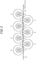
- FIG. 3 is a conceptual diagram illustrating a method for straightening a bend of the rail.
- the bend straightening of a rail is performed by passing a rail R through straightening rollers A to G disposed in zigzag along the feed direction of the rail.
- top surfaces of straightening rollers A, B, and C disposed below the feed line are arranged at an upper side than bottom surfaces of straightening rollers D, E, F and G disposed above the feed line.
- straightening rollers in total that is, three straightening rollers in the lower side of the figure and four straightening rollers in the upper side of the figure are applied with straightening loads of F A , F B , F C , F D , F E , F F , and F G , among which, the largest straightening load is 50 tf or more.
- the straightening load is less than 50 tf, strains cannot be accumulated in the rail, and the heat treatment described below would not improve a 0.2 % proof stress sufficiently, thus decreasing an improvement margin of rolling contact fatigue resistance.
- Strains accumulated in the rail by straightening treatment is changed depending on the straightening load and the cross-sectional area of the rail (size of the rail) to be subjected to the straightening treatment.
- the rail to be used under high axle load conditions which is mainly targeted in the disclosure has a size of 115 lbs, 136 lbs, and 141 lbs in the North America AREMA Standard which has a relatively large cross-section, and a size of 50 kgN and 60 kgN in the JIS Standard.
- the rail having such a size is applied with a straightening load of 50 tf or more, enough strains can be accumulated in the rail to sufficiently improve a 0.2 % proof stress after heat treatment.
- a rail is held in a temperature range of 150 °C or more and 400 °C or less for 0.5 hours or more and 10 hours or less.
- the holding temperature is less than 150 °C or more than 400 °C
- improvement margins of a 0.2 % proof stress and rolling contact fatigue resistance are decreased.
- the holding time in the temperature range is less than 0.5 hours or more than 10 hours
- improvement margins of a 0.2 % proof stress and rolling contact fatigue resistance are decreased.
- a furnace or a high-frequency heat treatment device can be used.
- a 0.2 % proof stress after the heat treatment is improved by 40 MPa or more relative to a 0.2 % proof stress before the heat treatment.
- the 0.2 % proof stress of the rail needs to be improved to limit a plastic deformation area as much as possible.
- the 0.2 % proof stress can be improved by adding alloying elements, which, however, rather deteriorates rolling contact fatigue resistance of the rail by the generation of an abnormal structure such as martensite.
- heat treatment under the aforementioned conditions is effective.
- the 0.2 % proof stress can be improved by performing optimal heat treatment.
- the "improvement margin of a 0.2 % proof stress" can be determined as a difference between 0.2 % proof stresses obtained in tensile tests before and after aging and heat treatment (a 0.2 % proof stress after aging and heat treatment - a 0.2 % proof stress before aging and heat treatment).
- a tensile test was performed on each obtained rail to measure its 0.2 % proof stress, tensile strength, and elongation. Further, a rolling contact fatigue resistance test was performed to measure rolling contact fatigue resistance of each rail. The measurement method was as follows.
- tensile test pieces were collected from the portion illustrated in FIG. 1 . Specifically, tensile test pieces having a diameter of parallel portion as described in ASTM A370 of 12.7 mm were collected from a position described in 2.1.3.4 of Chapter 4 of AREMA (see FIG. 1 ). Next, using the obtained tensile test pieces, a tensile test was performed under conditions of a tension speed of 1 mm/min and a gauge length of 50 mm to measure 0.2 % proof stress, tensile strength, and elongation. The measurement values were listed in Table 2.
- the tensile test was performed on test pieces of heads of the rails collected from immediately after the straightening treatment. For rails of No. 1 and No. 2, the tensile test was also performed on test pieces of heads of the rails collected 10 hours after the straightening treatment without the heat treatment. For the other rails than those of No. 1 and No. 2, the tensile test was also performed on test pieces of heads of the rails collected after the heat treatment under heat treatment conditions listed in Table 2.
- Rolling contact fatigue resistance was evaluated using a Nishihara type wear test apparatus and simulating actual contact conditions between a rail and a wheel. Specifically, cylinder test pieces having a diameter of 30 mm (an outer diameter of 30 mm and an inner diameter of 16 mm) with a contact surface being a curved surface having a radius of curvature of 15 mm were collected from heads of the rails as illustrated in FIG. 2A after the straightening treatment. Such pieces are also collected from heads of the rails as illustrated in FIG. 2A after the heat treatment or 10 hours after the straightening treatment without the heat treatment. The cylinder test pieces were fed to the test apparatus as illustrated in FIG.
- the wheel material illustrated in FIGS. 2A and 2B was subjected to the test, the wheel material being obtained by heating a round bar with a diameter of 33 mm to 900 °C, the bar having a chemical composition containing, in mass%, 0.76 % C, 0.35 % Si, 0.85 % Mn, 0.017 % P, 0.008 % S, and 0.25 % Cr with the balance being Fe and inevitable impurities, holding the bar for 40 minutes, subsequently allowing it to be naturally cooled, and forming it into a wheel material as illustrated in FIG. 2B .
- the hardness of the wheel material was HV280.
- the rail of Comparative Example No. 1 in Example 1 was an actually-used pearlitic rail having the C content of 0.81 %.
- rails of Examples according to the disclosure had a more excellent 0.2 % proof stress than the rail of Comparative Example No. 1 by 40 MPa or more and exhibited an improvement margin of rolling contact fatigue resistance of 10 % or more.
- the rails of Comparative Examples which did not satisfy the conditions of the disclosure were inferior in at least one of 0.2 % proof stress, elongation, and rolling contact fatigue resistance.
- the rails of Examples satisfying the conditions of the disclosure had a more excellent 0.2 % proof stress than the rail of Comparative Example No. 1 by 40 MPa or more and exhibited an improvement margin of rolling contact fatigue resistance of 10 % or more.
- the rails of Comparative Examples which did not satisfy the conditions of the disclosure were inferior in at least one of 0.2 % proof stress and rolling contact fatigue resistance.
Landscapes
- Chemical & Material Sciences (AREA)
- Engineering & Computer Science (AREA)
- Mechanical Engineering (AREA)
- Materials Engineering (AREA)
- Metallurgy (AREA)
- Organic Chemistry (AREA)
- Physics & Mathematics (AREA)
- Thermal Sciences (AREA)
- Crystallography & Structural Chemistry (AREA)
- Heat Treatment Of Steel (AREA)
- Heat Treatment Of Articles (AREA)
Abstract
Description
- The disclosure relates to method for producing a rail, in particular a high-strength pearlitic rail. Specifically, because this kind of rail is used under severe high axle load conditions such as in mining railways which are weighted with heavy freight cars and often have steep curves, the disclosure provides a method for providing a high-strength pearlitic rail having excellent rolling contact fatigue resistance which is suitable for prolonging the rail service life.
- In heavy haul railways mainly built to transport ore, the load applied to the axle of a freight car is much higher than that in passenger cars, and rails and wheels are used in increasingly harsh environments. For such a rail used in heavy haul railways, specifically, in railways on which trains and freight cars run with high loading weight, steel having a pearlite structure is conventionally primarily used, from the viewpoint of the importance of rolling contact fatigue resistance. In recent years, however, to increase loading weight on freight cars and improve the efficiency of transportation, there has been demand for further improvement of rolling contact fatigue resistance of rails.
- Consequently, there have been made various studies for further improvement of rolling contact fatigue resistance. For example,
JP 5292875 B JP 5493950 B JP 2000-219939 A JP 5453624 B -
- PTL 1:
JP 5292875 B - PTL 2:
JP 5493950 B - PTL 3:
JP 2000-219939 A - PTL 4:
JP 5453624 B - A rail obtained through hot rolling and accelerated cooling is typically subjected to straightening treatment to eliminate a bend of the rail. In this straightening treatment, the 0.2 % proof stress is significantly decreased by the Bauschinger effect. Specifically, to impart straightness to a rail, for example, the rail has to be straightened with a load of 30 tf to 70 tf. When straightening treatment is performed with such a high load, the 0.2 % proof stress after the straightening treatment is significantly decreased as compared with before the treatment.
- Then, alloying elements need to be added to sufficiently enhance the 0.2 % proof stress before straightening treatment of a rail, but adding a large amount of alloying elements rather causes an abnormal structure other than a pearlite structure. Thus, adding more alloying elements than the present level is difficult. Therefore, a decrease in the 0.2 % proof stress caused by the Bauschinger effect needs to be prevented by a method other than the addition of alloying elements.
- All the techniques described in PTL 1 to PTL 4, however, merely improve the 0.2 % proof stress in a stage before a rail is subjected to straightening treatment. Any of the techniques cannot avoid a decrease in the 0.2 % proof stress after straightening treatment.
- Specifically, the technique described in PTL 1 defines a ratio of the Mn content and the Cr content, and a ratio of the V content and the N content, but the rail loses the 0.2 % proof stress in straightening treatment as described above. Thus, the 0.2 % proof stress cannot be sufficiently maintained after straightening treatment only by defining the ratio of alloying elements.
- PTL 2 proposes to define contents of C and Cu and to perform post heat treatment at heating temperature of 450 °C to 550 °C for 0.5 h to 24 h, but the heating temperature is high only to decrease the 0.2 % proof stress because of recovery of dislocation. Thus, the 0.2 % proof stress is more decreased after straightening treatment.
- The technique described in PTL 3 sets the C content to more than 0.85 % and increases the amount of cementite, thus ensuring a high 0.2 % proof stress. On the other hand, a decrease in elongation tends to cause cracking, thus making it difficult to ensure rolling contact fatigue resistance.
- The pearlite steel rail of PTL 4 has a 0.2 % proof stress as low as less than 800 MPa, and actually has difficulties to ensure rolling contact fatigue resistance.
- The disclosure has been developed in light of the above circumstances. It could be helpful to provide a method for achieving a high 0.2 % proof stress in a rail after straightening treatment, the high 0.2 % proof stress being effective at improving rolling contact fatigue resistance of the rail.
- We studied to address this issue, and found that optimizing the chemical composition of a rail, and additionally, properly performing heating treatment after straightening treatment is effective at improving the 0.2 % proof stress of a pearlitic rail which has been subjected to straightening treatment. Based on the findings, we completed the disclosure.
- The disclosure is based on the findings described above and has the following primary features.
- 1. A method for producing a rail comprising: hot rolling a steel raw material to obtain a rail, the steel raw material having a chemical composition containing (consisting of), in mass%,
C: 0.70 % to 0.85 %,
Si: 0.1 % to 1.5 %,
Mn: 0.4 % to 1.5 %,
P: 0.035 % or less,
S: 0.010 % or less, and
Cr: 0.05 % to 1.50 %
with the balance being Fe and inevitable impurities; straightening the rail with a load of 50 tf or more; and subsequently subjecting the rail to heat treatment in which the rail is held in a temperature range of 150 °C or more and 400 °C or less for 0.5 hours or more and 10 hours or less. - 2. The method for producing a rail according to 1., wherein the chemical composition further contains, in mass%, at least one selected from the group consisting of
V: 0.30 % or less,
Cu: 1.0 % or less,
Ni: 1.0 % or less,
Nb: 0.05 % or less,
Mo: 0.5 % or less,
Al: 0.07 % or less,
W: 1.0 % or less,
B: 0.005 % or less, and
Ti: 0.05 % or less. - According to the disclosure, it is possible to provide a high-strength pearlitic rail which exhibits an excellent 0.2 % proof stress after straightening treatment and thus can be suitably used in heavy haul railways.
- In the accompanying drawings:
-
FIG. 1 is a schematic diagram of a rail head illustrating a collecting position of a tensile test piece; -
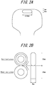
FIGS. 2A and 2B are each a schematic diagram of a rail head illustrating a collecting position of a rolling contact fatigue test piece; and -
FIG. 3 is a schematic diagram illustrating an overview of bend straightening of a rail. - Our method for producing a rail will be specifically explained below.
- First, it is important that a steel raw material to produce a rail has the chemical composition described above. Reasons for limiting the chemical composition as described above are explained for each element. The unit of the content of each component is "mass%", but it is abbreviated as "%".
- C is an element that forms cementite in a pearlite structure and has the effect of improving the 0.2 % proof stress in heat treatment after straightening treatment. Therefore, the addition of C is necessary to ensure the 0.2 % proof stress in a rail. As the C content increases, the 0.2 % proof stress is improved. Specifically, when the C content is less than 0.70 %, it is difficult to obtain an excellent 0.2 % proof stress after the heat treatment. On the other hand, when the C content is beyond 0.85 %, pro-eutectoid cementite is formed at prior austenite grain boundaries, ending up deteriorating rolling contact fatigue resistance of a rail. Therefore, the C content is set to 0.70 % to 0.85 %, and preferably, 0.75 % to 0.85 %.
- Si is an element that functions as a deoxidizer. Further, Si has an effect of improving the 0.2 % proof stress of a rail by solid solution strengthening of ferrite in pearlite. Therefore, the Si content needs to be 0.1 % or more. On the other hand, a Si content beyond 1.5 % produces a large amount of oxide-based inclusions because Si has a high strength of bonding with oxygen, thus deteriorating rolling contact fatigue resistance. Therefore, the Si content is set to 0.1 % to 1.5 %, and preferably, 0.15 % to 1.5 %.
- Mn is an element that improves the strength of a rail by decreasing the transformation temperature of steel to thereby shorten the lamellar spacing. A Mn content less than 0.4 %, however, cannot achieve a sufficient effect. On the other hand, a Mn content beyond 1.5 % tends to generate a martensite structure by microsegregation of steel, thus deteriorating rolling contact fatigue resistance. Therefore, the Mn content is set to 0.4 % to 1.5 %, and preferably, 0.4 % to 1.4 %.
- A P content beyond 0.035 % deteriorates ductility of a rail. Therefore, the P content is set to 0.035 % or less. On the other hand, the lower limit of the P content is not limited, and may be 0 %, although industrially more than 0 %. Excessively decreasing the P content causes an increase in refining cost. Thus, from the perspective of economic efficiency, the P content is preferably set to 0.001 % or more, and more preferably, 0.025 % or less.
- S exists in steel mainly in the form of an A type (sulfide-based) inclusion. A S content beyond 0.010 % significantly increases the amount of the inclusions and generates coarse inclusions, thus deteriorating rolling contact fatigue resistance. Setting the S content to less than 0.0005 % causes an increase in refining cost. Thus, from the perspective of economic efficiency, the S content is preferably set to 0.0005 % or more, more preferably, 0.009 % or less.
- Cr is an element that has an effect of improving the 0.2 % proof stress by solid solution strengthening of cementite in pearlite. To achieve this effect, the Cr content needs to be 0.05 % or more. On the other hand, a Cr content beyond 1.50 % generates a martensite structure by solid solution strengthening of Cr, ending up deteriorating rolling contact fatigue resistance. Therefore, the Cr content is set to 0.05 % to 1.50 %, and preferably 0.10 % to 1.50 %.
- Our rail comprises the aforementioned composition as a steel raw material, with the balance being Fe and inevitable impurities. The balance may be Fe and inevitable impurities, and may further contain the following elements within a range which does not substantially affect the action and effect of the disclosure.
- Specifically, the balance may further contain as necessary at least one selected from the group consisting of
V: 0.30 % or less,
Cu: 1.0 % or less,
Ni: 1.0 % or less,
Nb: 0.05 % or less,
Mo: 0.5 % or less,
Al: 0.07 % or less,
W: 1.0 % or less,
B: 0.005 % or less, and
Ti: 0.05 % or less. - V is an element that has an effect of precipitating as a carbonitride during and after rolling and improving the 0.2 % proof stress by precipitation strengthening. Therefore, 0.001 % or more of V is preferably added. On the other hand, a V content beyond 0.30 % causes the precipitation of a large amount of coarse carbonitrides, thus deteriorating rolling contact fatigue resistance. Therefore, in the case of adding V, the V content is preferably set to 0.30 % or less.
- As with Cr, Cu is an element that has an effect of improving the 0.2 % proof stress by solid solution strengthening. Therefore, 0.001 % or more of Cu is preferably added. On the other hand, a Cu content beyond 1.0 % causes Cu cracking. Therefore, in the case of adding Cu, the Cu content is preferably set to 1.0 % or less.
- Ni has an effect of improving the 0.2 % proof stress without deteriorating ductility. Therefore, 0.001 % or more of Ni is preferably added. In addition, adding Ni along with Cu can prevent Cu cracking. Thus, in the case of adding Cu, Ni is preferably added. On the other hand, a Ni content beyond 1.0 % increases quench hardenability to produce martensite, deteriorating rolling contact fatigue resistance. Therefore, in the case of adding Ni, the Ni content is preferably set to 1.0 % or less.
- Nb precipitates as a carbonitride during and after rolling and improves the 0.2 % proof stress of a pearlitic rail. Therefore, 0.001 % or more of Nb is preferably added. On the other hand, a Nb content beyond 0.05 % causes the precipitation of a large amount of coarse carbonitrides, thus deteriorating ductility. Therefore, in the case of adding Nb, the Nb content is preferably set to 0.05 % or less.
- Mo precipitates as a carbonitride during and after rolling and improves the 0.2 % proof stress by precipitation strengthening. Therefore, 0.001 % or more of Mo is preferably added. On the other hand, a Mg content beyond 0.5 % produces martensite, thus deteriorating rolling contact fatigue resistance. Therefore, in the case of adding Mo, the Mo content is preferably set to 0.5 % or less.
- Al is an element that is added as a deoxidizer. Therefore, 0.001 % or more of Al is preferably added. On the other hand, an Al content beyond 0.07 % produces a large amount of oxide-based inclusions because Al has a high strength of bonding with oxygen, thus deteriorating rolling contact fatigue resistance. Therefore, the Al content is preferably set to 0.07 % or less.
- W precipitates as a carbonitride during and after rolling and improves the 0.2 % proof stress by precipitation strengthening. Therefore, 0.001 % or more of W is preferably added. On the other hand, a W content beyond 1.0 % produces martensite, thus deteriorating rolling contact fatigue resistance. Therefore, in the case of adding W, the W content is preferably set to 1.0 % or less.
- B precipitates as a nitride during and after rolling, and improves the 0.2 % proof stress by precipitation strengthening. Therefore, 0.0001 % or more of B is preferably added. A B content beyond 0.005 % produces martensite, thus deteriorating rolling contact fatigue resistance. Therefore, in the case of adding B, the B content is preferably set to 0.005 % or less.
- Ti precipitates as a carbide, a nitride, or a carbonitride during and after rolling, and improves the 0.2 % proof stress by precipitation strengthening. Therefore, 0.001 % or more of Ti is preferably added. On the other hand, a Ti content beyond 0.05 % produces coarse carbides, nitrides, or carbonitrides, thus deteriorating rolling contact fatigue resistance. Therefore, in the case of adding Ti, the Ti content is preferably 0.05 % or less.
- Next, a method for producing our rail will be described.
- Our rail can be produced by making a rail through hot rolling and cooling according to a usual method and subsequently subjecting the rail to straightening treatment with loads of 50 tf or more, and then to heat treatment under predetermined conditions.
- The rail is produced by hot rolling, for example, in accordance with the following procedures.
- First, steel is melted in a converter or an electric heating furnace and subjected as necessary to secondary refining such as degassing. Subsequently, the chemical composition of the steel is adjusted within the aforementioned range. Next, the steel is subjected to continuous casting to make a steel raw material such as bloom. Subsequently, the steel raw material is heated in a heating furnace to 1200 °C to 1350 °C and hot rolled to obtain a rail. The hot rolling is preferably performed at rolling finish temperature: 850 °C to 1000 °C and the rail after the hot rolling is preferably cooled at cooling rate: 1 °C/s to 10 °C/s.
- After the cooling following the hot rolling is finished, the rail is subjected to straightening treatment with loads of 50 tf or more to straighten a bend of the rail. The bend of the rail is straightened by passing the rail through straightening rollers disposed in zigzag along the feed direction of the rail and subjecting the rail to repeated bending/bend restoration deformation.
FIG. 3 is a conceptual diagram illustrating a method for straightening a bend of the rail. The bend straightening of a rail is performed by passing a rail R through straightening rollers A to G disposed in zigzag along the feed direction of the rail. InFIG. 3 , top surfaces of straightening rollers A, B, and C disposed below the feed line are arranged at an upper side than bottom surfaces of straightening rollers D, E, F and G disposed above the feed line. By passing the rail through the straightening roller group, the rail is subjected to bending/bend restoration deformation. During the straightening, at least one of straightening loads applied to the straightening rollers A to G is 50 tf or more. For example, in the example ofFIG. 3 , seven straightening rollers in total, that is, three straightening rollers in the lower side of the figure and four straightening rollers in the upper side of the figure are applied with straightening loads of FA, FB, FC, FD, FE, FF, and FG, among which, the largest straightening load is 50 tf or more. When the straightening load is less than 50 tf, strains cannot be accumulated in the rail, and the heat treatment described below would not improve a 0.2 % proof stress sufficiently, thus decreasing an improvement margin of rolling contact fatigue resistance. - Strains accumulated in the rail by straightening treatment is changed depending on the straightening load and the cross-sectional area of the rail (size of the rail) to be subjected to the straightening treatment. Here, the rail to be used under high axle load conditions which is mainly targeted in the disclosure has a size of 115 lbs, 136 lbs, and 141 lbs in the North America AREMA Standard which has a relatively large cross-section, and a size of 50 kgN and 60 kgN in the JIS Standard. When the rail having such a size is applied with a straightening load of 50 tf or more, enough strains can be accumulated in the rail to sufficiently improve a 0.2 % proof stress after heat treatment.
- After the straightening treatment, it is important to perform heat treatment in which a rail is held in a temperature range of 150 °C or more and 400 °C or less for 0.5 hours or more and 10 hours or less. Specifically, when the holding temperature is less than 150 °C or more than 400 °C, improvement margins of a 0.2 % proof stress and rolling contact fatigue resistance are decreased. Further, when the holding time in the temperature range is less than 0.5 hours or more than 10 hours, improvement margins of a 0.2 % proof stress and rolling contact fatigue resistance are decreased. For the heat treatment, a furnace or a high-frequency heat treatment device can be used.
- By subjecting a rail made from a steel raw material having the aforementioned chemical composition to the aforementioned heat treatment after the straightening treatment, a 0.2 % proof stress after the heat treatment is improved by 40 MPa or more relative to a 0.2 % proof stress before the heat treatment.
- Specifically, to improve rolling contact fatigue resistance of the rail, the 0.2 % proof stress of the rail needs to be improved to limit a plastic deformation area as much as possible. The 0.2 % proof stress can be improved by adding alloying elements, which, however, rather deteriorates rolling contact fatigue resistance of the rail by the generation of an abnormal structure such as martensite. To prevent the generation of an abnormal structure and improve the 0.2 % proof stress, heat treatment under the aforementioned conditions is effective. The 0.2 % proof stress can be improved by performing optimal heat treatment.
- As used herein, the "improvement margin of a 0.2 % proof stress" can be determined as a difference between 0.2 % proof stresses obtained in tensile tests before and after aging and heat treatment (a 0.2 % proof stress after aging and heat treatment - a 0.2 % proof stress before aging and heat treatment).
- Steel raw materials (bloom) having a chemical composition listed in Table 1 were hot rolled to obtain rails having a size listed in Table 2. At that time, the heating temperature before the hot rolling was 1250 °C, and the delivery temperature was 900 °C. The hot-rolled rails were cooled to 400 °C at an average rate of 3 °C/s. Subsequently, the cooled rails were subjected to straightening treatment under conditions listed in Table 2, and then to heat treatment under conditions listed in Table 2. The rails of Comparative Examples of No. 1 and No. 2 were not subjected to heat treatment.
- A tensile test was performed on each obtained rail to measure its 0.2 % proof stress, tensile strength, and elongation. Further, a rolling contact fatigue resistance test was performed to measure rolling contact fatigue resistance of each rail. The measurement method was as follows.
- For heads of the obtained rails, tensile test pieces were collected from the portion illustrated in
FIG. 1 . Specifically, tensile test pieces having a diameter of parallel portion as described in ASTM A370 of 12.7 mm were collected from a position described in 2.1.3.4 of Chapter 4 of AREMA (seeFIG. 1 ). Next, using the obtained tensile test pieces, a tensile test was performed under conditions of a tension speed of 1 mm/min and a gauge length of 50 mm to measure 0.2 % proof stress, tensile strength, and elongation. The measurement values were listed in Table 2. - The tensile test was performed on test pieces of heads of the rails collected from immediately after the straightening treatment. For rails of No. 1 and No. 2, the tensile test was also performed on test pieces of heads of the rails collected 10 hours after the straightening treatment without the heat treatment. For the other rails than those of No. 1 and No. 2, the tensile test was also performed on test pieces of heads of the rails collected after the heat treatment under heat treatment conditions listed in Table 2.
- Rolling contact fatigue resistance was evaluated using a Nishihara type wear test apparatus and simulating actual contact conditions between a rail and a wheel. Specifically, cylinder test pieces having a diameter of 30 mm (an outer diameter of 30 mm and an inner diameter of 16 mm) with a contact surface being a curved surface having a radius of curvature of 15 mm were collected from heads of the rails as illustrated in
FIG. 2A after the straightening treatment. Such pieces are also collected from heads of the rails as illustrated inFIG. 2A after the heat treatment or 10 hours after the straightening treatment without the heat treatment. The cylinder test pieces were fed to the test apparatus as illustrated inFIG. 2B with a contact pressure of 2.2 GPa and a slip rate of -20 % under oil lubrication conditions. At the time when spalling occurred in a contact surface of the test pieces, the test pieces were determined to have reached their rolling contact fatigue life. As a standard when comparing the rolling contact fatigue life, an actually-used pearlite steel rail having the C content of 0.81 % was adopted. When the rolling contact fatigue time was 10 % or more longer than in the actually-used pearlite steel rail (A1), the rolling contact fatigue resistance was determined to have been improved. - The wheel material illustrated in
FIGS. 2A and 2B was subjected to the test, the wheel material being obtained by heating a round bar with a diameter of 33 mm to 900 °C, the bar having a chemical composition containing, in mass%, 0.76 % C, 0.35 % Si, 0.85 % Mn, 0.017 % P, 0.008 % S, and 0.25 % Cr with the balance being Fe and inevitable impurities, holding the bar for 40 minutes, subsequently allowing it to be naturally cooled, and forming it into a wheel material as illustrated inFIG. 2B . The hardness of the wheel material was HV280.Table 1 Steel sample ID Chemical composition (mass%)* Remarks C Si Mn P S Cr Al 0.81 0.25 1.18 0.009 0.005 0.25 Conforming Steel A2 0.84 0.51 0.62 0.011 0.004 0.77 Conforming Steel A3 0.69 0.24 0.82 0.008 0.007 0.15 Comparative Steel *The balance is Fe and inevitable impurities Table 2 No. Steel sample ID Size Straightening load (tf) Heat treatment conditions Measurement results Remarks Holding temperature (°C) Holding time (time) Before heat treatment After heat treatment Improvement margin of 0.2 % proof stress (MPa) Improvement margin of rolling contact fatigue resistance (%) 0.2% proof stress (Mpa) Tensile strength (MPa) Elongation (%) 0.2% proof stress (Mpa) Tensile strength (MPa) Elongation (%) 1 A1 50kgN 80 - - 921 1403 12.0 922 1404 12.1 1 Standard Comparative Example 2 A2 50kgN 80 - - 932 1432 12.1 935 1445 12.2 3 2 Comparative Example 3 A2 136lbs 80 140 0.5 933 1433 12.5 945 1451 12.5 12 4 Comparative Example 4 A2 50kgN 80 140 10 932 1432 12.3 952 1421 14.7 20 5 Comparative Example 5 A2 141lbs 50 150 0.5 934 1432 12.5 981 1451 12.5 47 14 Example 6 A2 50kgN 50 150 10 931 1433 12.3 993 1421 14.7 62 16 Example 7 A2 136lbs 100 200 0.5 931 1440 12.5 979 1307 15.2 48 15 Example 8 A2 141lbs 50 200 10 933 1439 12.6 1003 1288 15.6 70 20 Example 9 A2 50kgN 50 300 0.5 934 1432 12.5 988 1434 12.4 54 15 Example 10 A2 141lbs 120 300 10 931 1433 12.7 1003 1439 12.7 72 20 Example 11 A2 50kgN 70 400 0.5 931 1433 12.8 971 1422 12.6 40 12 Example 12 A2 141lbs 70 400 10 932 1433 12.5 994 1441 12.8 62 17 Example 13 A2 50kgN 80 410 0.5 933 1439 12.5 966 1453 12.1 33 9 Comparative Example 14 A2 141lbs 80 410 10 934 1438 12.4 951 1437 12.6 17 5 Comparative Example 15 A2 50kgN 80 300 0.4 935 1440 12.4 966 1453 12.1 31 8 Comparative Example 16 A2 136lbs 100 300 11 934 1431 12.4 959 1429 12.6 25 5 Comparative Example 17 A3 50kgN 80 300 0.5 892 1387 12.7 911 1453 12.1 19 5 Comparative Example 18 A3 50kgN 45 300 0.5 888 1389 12.8 922 1391 12.7 34 9 Comparative Example 19 A2 136lbs 45 400 0.5 927 1435 12.6 927 1435 12.7 0 2 Comparative Example - The rail of Comparative Example No. 1 in Example 1 was an actually-used pearlitic rail having the C content of 0.81 %. As seen from the results listed in Table 2, rails of Examples according to the disclosure had a more excellent 0.2 % proof stress than the rail of Comparative Example No. 1 by 40 MPa or more and exhibited an improvement margin of rolling contact fatigue resistance of 10 % or more. On the other hand, the rails of Comparative Examples which did not satisfy the conditions of the disclosure were inferior in at least one of 0.2 % proof stress, elongation, and rolling contact fatigue resistance.
- Rails were made in the same procedures as in Example 1 other than using steel having a chemical composition listed in Table 3. A tensile test and measurement of rolling contact fatigue resistance were performed on the rails in the same way as in Example 1. Heat treatment conditions and the measurement results are presented in Table 4.
- As seen from the results listed in Table 4, the rails of Examples satisfying the conditions of the disclosure had a more excellent 0.2 % proof stress than the rail of Comparative Example No. 1 by 40 MPa or more and exhibited an improvement margin of rolling contact fatigue resistance of 10 % or more. On the other hand, the rails of Comparative Examples which did not satisfy the conditions of the disclosure were inferior in at least one of 0.2 % proof stress and rolling contact fatigue resistance.
Table 3 Steel sample ID Chemical Composition (mass%)* Remarks C Si Mn P S Cr Cu Ni Mo V Nb Al W B Ti A1 0.81 0.25 1.18 0.011 0.006 0.25 - - - - - - - - - Conforming Steel B1 0.83 1.50 0.49 0.014 0.007 0.26 - - - - - - - - - Conforming Steel B2 0.83 0.25 0.85 0.005 0.007 0.61 - - - - - - - - - Conforming Steel B3 0.70 0.42 0.40 0.003 0.006 1.50 - - - - - - - - - Conforming Steel B4 0.84 0.88 0.46 0.016 0.005 0.79 - - - - - - - - - Conforming Steel B5 0.83 0.87 0.47 0.003 0.006 1.46 - - - - - - - - - Conforming Steel B6 0.84 0.22 1.20 0.005 0.007 0.21 - - - - - - - - - Conforming Steel B7 0.81 0.69 0.56 0.015 0.007 0.79 - - - - - - - - - Conforming Steel B8 0.71 1.16 1.34 0.016 0.004 0.88 - - - - - - - - - Conforming Steel B9 0.84 1.06 0.83 0.019 0.006 0.05 - - - - - - - - - Conforming Steel B10 0.85 0.48 0.71 0.016 0.004 0.32 - - - - - - - - - Conforming Steel B11 0.68 0.25 0.81 0.015 0.006 0.05 - - - - - - - - - Comparative Steel B12 0.86 0.24 0.81 0.015 0.007 0.22 - - - - - - - - - Comparative Steel B13 0.72 0.04 0.81 0.015 0.005 0.21 - - - - - - - - - Comparative Steel B14 0.82 1.55 0.82 0.014 0.005 0.99 - - - - - - - - - Comparative Steel B15 0.72 0.25 0.34 0.015 0.005 0.18 - - - - - - - - - Comparative Steel B16 0.84 0.29 1.55 0.011 0.005 0.99 - - - - - - - - - Comparative Steel B17 0.81 0.63 0.81 0.006 0.003 0.01 - - - - - - - - - Comparative Steel B18 0.85 0.59 0.81 0.007 0.003 1.55 - - - - - - - - - Comparative Steel B19 0.84 0.55 0.55 0.014 0.005 0.79 - - - 0.05 - - - - - Conforming Steel B20 0.84 0.51 0.61 0.008 0.004 0.74 - - - 0.15 - - - - - Conforming Steel B21 0.84 0.25 1.10 0.006 0.005 0.25 - - - - 0.04 - - - - Conforming Steel B22 0.84 0.35 1.05 0.003 0.004 0.29 - - 0.30 - - - - - - Conforming Steel B23 0.84 0.55 0.55 0.011 0.005 0.62 0.30 0.50 - - - - - - - Conforming Steel B24 0.84 0.25 1.20 0.004 0.005 0.29 - - - - - 0.07 0.60 - - Conforming Steel B25 0.84 0.88 0.55 0.005 0.005 0.45 - - - - - - - 0.003 0.05 Conforming Steel B26 0.84 0.95 0.56 0.011 0.005 0.79 - - - 0.05 - - - - - Conforming Steel *The balance is Fe and inevitable impurities Table 4 No. Steel sample ID Size Straightening load (tf) Heat treatment conditions Measurement results Remarks Holding temperature (°C) Holding time (time) Before heat treatment After heat treatment Improvement margin of 0.2 % proof stress (MPa) Improvement margin of rolling contact fatigue resistance (%) 0.2 % proof stress (Mpa) Tensile strength (MPa) Elongation (%) 0.2% proof stress (Mpa) Tensile strength (MPa) Elongation (%) 19 A1 136lbs 80 - - 921 1403 12.0 922 1404 12.1 1 Standard Comparative Example 20 B1 141lbs 80 200 4 933 1432 12.3 972 1435 12.4 39 11 Example 21 B2 50kgN 80 300 4 929 1431 12.2 974 1439 12.3 45 13 Example 22 B3 136lbs 80 300 10 887 1387 13.1 927 1389 12.9 40 11 Example 23 B4 141lbs 80 200 6 933 1433 12.8 983 1432 12.7 50 14 Example 24 B5 50kgN 80 300 3 952 1441 12.3 995 1442 12.3 43 13 Example 25 B6 50kgN 80 300 10 918 1398 11.7 960 1423 11.5 42 13 Example 26 B7 136lbs 80 300 10 929 1422 12.5 974 1429 12.2 45 14 Example 27 B8 50kgN 80 400 10 929 1423 12.6 978 1423 12.4 49 15 Example 28 B9 136lbs 80 300 0.5 934 1439 12.6 974 1438 12.5 40 12 Example 29 B10 50kgN 80 300 6 929 1422 12.3 980 1430 12.4 51 16 Example 30 B11 141lbs 80 300 3 889 1377 12.4 921 1387 12.3 32 9 Comparative Example 31 B12 136lbs 80 300 0.5 948 1421 9.5 989 1420 9.2 41 9 Comparative Example 32 B13 50kgN 80 300 2 892 1387 12.2 931 1389 12.2 39 9 Comparative Example 33 B14 136lbs 80 300 4 944 1429 12.3 984 1430 12.3 40 9 Comparative Example 34 B15 50kgN 80 300 3 889 1387 12.3 920 1392 12.5 31 7 Comparative Example 35 B16 136lbs 80 300 3 921 1428 12.4 963 1429 12.4 42 8 Comparative Example 36 B17 141lbs 80 300 5 879 1399 12.2 917 1401 12.2 38 8 Comparative Example 37 B18 50kgN 80 300 6 922 1432 12.3 965 1433 12.3 43 7 Comparative Example 38 B19 136lbs 100 300 3 933 1433 12.4 984 1430 12.4 51 15 Example 39 B20 50kgN 50 250 4 942 1439 12.5 984 1433 12.2 42 11 Example 40 B21 136lbs 80 300 4 934 1433 12.1 979 1435 12.1 45 13 Example 41 B22 136lbs 50 300 2 929 1438 12.0 969 1439 12.4 40 11 Example 42 B23 50kgN 80 250 6 941 1432 12.3 983 1433 12.3 42 12 Example 43 B24 136lbs 80 350 3 923 1430 12.2 968 1439 12.4 45 14 Example 44 B25 141lbs 50 300 6 923 1439 12.2 968 1440 12.5 45 14 Example 45 B26 136lbs 80 300 1 931 1423 12.3 974 1433 12.3 43 12 Example
Claims (2)
- A method for producing a rail comprising:hot rolling a steel raw material to obtain a rail, the steel raw material having a chemical composition containing, in mass%,C: 0.70 % to 0.85 %,Si: 0.1 % to 1.5 %,Mn: 0.4 % to 1.5 %,P: 0.035 % or less,S: 0.010 % or less, andCr: 0.05 % to 1.50 % with the balance being Fe and inevitable impurities;straightening the rail with a load of 50 tf or more; andsubsequently subjecting the rail to heat treatment in which the rail is held in a temperature range of 150 °C or more and 400 °C or less for 0.5 hours or more and 10 hours or less.
- The method for producing a rail according to claim 1, wherein the chemical composition further contains, in mass%, at least one selected from the group consisting of
V: 0.30 % or less,
Cu: 1.0 % or less,
Ni: 1.0 % or less,
Nb: 0.05 % or less,
Mo: 0.5 % or less,
Al: 0.07 % or less,
W: 1.0 % or less,
B: 0.005 % or less, and
Ti: 0.05 % or less.
Applications Claiming Priority (2)
| Application Number | Priority Date | Filing Date | Title |
|---|---|---|---|
| JP2017054989 | 2017-03-21 | ||
| PCT/JP2018/011191 WO2018174094A1 (en) | 2017-03-21 | 2018-03-20 | Method for producing rail |
Publications (3)
| Publication Number | Publication Date |
|---|---|
| EP3604563A4 EP3604563A4 (en) | 2020-02-05 |
| EP3604563A1 true EP3604563A1 (en) | 2020-02-05 |
| EP3604563B1 EP3604563B1 (en) | 2022-06-08 |
Family
ID=63585439
Family Applications (1)
| Application Number | Title | Priority Date | Filing Date |
|---|---|---|---|
| EP18772424.0A Active EP3604563B1 (en) | 2017-03-21 | 2018-03-20 | Method for producing rail |
Country Status (8)
| Country | Link |
|---|---|
| US (1) | US11111555B2 (en) |
| EP (1) | EP3604563B1 (en) |
| JP (1) | JP6555447B2 (en) |
| CN (1) | CN110337498A (en) |
| AU (1) | AU2018240808B2 (en) |
| BR (1) | BR112019019695B1 (en) |
| CA (1) | CA3054643C (en) |
| WO (1) | WO2018174094A1 (en) |
Families Citing this family (3)
| Publication number | Priority date | Publication date | Assignee | Title |
|---|---|---|---|---|
| CN113088811A (en) * | 2021-03-04 | 2021-07-09 | 天津荣程联合钢铁集团有限公司 | Niobium-containing alloy steel and preparation method thereof |
| CN116716553A (en) * | 2023-05-04 | 2023-09-08 | 包头钢铁(集团)有限责任公司 | A smelting method to improve the falling weight pass rate of high-speed rails |
| CN116970868B (en) * | 2023-08-09 | 2025-06-10 | 中天钢铁集团有限公司 | A high-strength and high-wear-resistant alloy tool steel and smelting method thereof |
Family Cites Families (15)
| Publication number | Priority date | Publication date | Assignee | Title |
|---|---|---|---|---|
| EP0190448A1 (en) * | 1985-01-18 | 1986-08-13 | Krupp Stahl AG | Process for reducing residual stress of roller-straightened steel rails |
| JPH01139725A (en) * | 1987-11-27 | 1989-06-01 | Nippon Steel Corp | Heat treatment for steel rail excellent in fracture-resisting characteristic |
| JPH07185660A (en) * | 1993-12-27 | 1995-07-25 | Nippon Steel Corp | Rail roller straightening method |
| CN1083013C (en) * | 1996-09-29 | 2002-04-17 | 攀枝花钢铁(集团)公司 | Heat treatment method and device for producing high-strength steel rail by using rolling waste heat |
| JP2000219939A (en) | 1999-02-01 | 2000-08-08 | Nippon Steel Corp | Pearlitic rail with excellent wear resistance and surface damage resistance |
| CN100471974C (en) * | 2005-12-05 | 2009-03-25 | 鞍钢股份有限公司 | Steel rail with bainite structure having excellent fatigue resistance and production method thereof |
| CN101405419B (en) * | 2006-03-16 | 2012-06-27 | 杰富意钢铁株式会社 | High-strength pearlitic steel rail with excellent delayed failure resistance |
| CN100482812C (en) * | 2006-09-12 | 2009-04-29 | 攀枝花钢铁(集团)公司 | Rail heat processing method and rail heat processing unit |
| JP5292875B2 (en) | 2007-10-10 | 2013-09-18 | Jfeスチール株式会社 | Internal high-hardness pearlitic steel rail with excellent wear resistance, fatigue damage resistance and delayed fracture resistance, and manufacturing method thereof |
| JP5453624B2 (en) | 2009-10-16 | 2014-03-26 | Jfeスチール株式会社 | Perlite steel rail with excellent crack resistance |
| JP5493950B2 (en) | 2010-02-08 | 2014-05-14 | 新日鐵住金株式会社 | Manufacturing method of pearlite rail with excellent wear resistance |
| CN106460117A (en) * | 2014-06-11 | 2017-02-22 | 杰富意钢铁株式会社 | Wheel for railroad car and method for manufacturing wheel for railroad car |
| CN104561816B (en) * | 2015-01-07 | 2016-08-31 | 攀钢集团攀枝花钢铁研究院有限公司 | The rail of a kind of high-strength, fatigue-resistant function admirable and production method thereof |
| US20180327880A1 (en) | 2015-05-14 | 2018-11-15 | Jfe Steel Corporation | Method of producing steel material, apparatus that cools steel material, and steel material |
| CN105018705B (en) * | 2015-08-11 | 2017-12-15 | 攀钢集团攀枝花钢铁研究院有限公司 | A kind of hypereutectoid rail and preparation method thereof |
-
2018
- 2018-03-20 JP JP2019507710A patent/JP6555447B2/en active Active
- 2018-03-20 WO PCT/JP2018/011191 patent/WO2018174094A1/en not_active Ceased
- 2018-03-20 CN CN201880014205.1A patent/CN110337498A/en active Pending
- 2018-03-20 BR BR112019019695-1A patent/BR112019019695B1/en active IP Right Grant
- 2018-03-20 CA CA3054643A patent/CA3054643C/en active Active
- 2018-03-20 EP EP18772424.0A patent/EP3604563B1/en active Active
- 2018-03-20 US US16/488,343 patent/US11111555B2/en active Active
- 2018-03-20 AU AU2018240808A patent/AU2018240808B2/en active Active
Also Published As
| Publication number | Publication date |
|---|---|
| JPWO2018174094A1 (en) | 2019-06-27 |
| JP6555447B2 (en) | 2019-08-07 |
| AU2018240808B2 (en) | 2020-07-23 |
| EP3604563B1 (en) | 2022-06-08 |
| CN110337498A (en) | 2019-10-15 |
| WO2018174094A1 (en) | 2018-09-27 |
| US11111555B2 (en) | 2021-09-07 |
| AU2018240808A1 (en) | 2019-09-19 |
| US20200277682A1 (en) | 2020-09-03 |
| CA3054643C (en) | 2021-09-28 |
| BR112019019695B1 (en) | 2023-05-16 |
| EP3604563A4 (en) | 2020-02-05 |
| BR112019019695A2 (en) | 2020-04-14 |
| CA3054643A1 (en) | 2018-09-27 |
Similar Documents
| Publication | Publication Date | Title |
|---|---|---|
| EP2135966B1 (en) | Pearlite steel rail of high internal hardness type excellent in wear resistance and fatigue failure resistance and process for production of the same | |
| US8168011B2 (en) | High-strength steel wire excellent in ductility and method of manufacturing the same | |
| US20160194729A1 (en) | High-strength and highly fatigue-resistant steel rail and production method thereof | |
| JP5282506B2 (en) | Internal high hardness type pearlitic steel rail with excellent wear resistance and fatigue damage resistance and method for manufacturing the same | |
| JP2009108396A (en) | Internal high-hardness pearlitic steel rail with excellent wear resistance, fatigue damage resistance and delayed fracture resistance, and manufacturing method thereof | |
| EP4174191A1 (en) | Rail having excellent fatigue crack propagation resistance characteristics, and method for producing same | |
| EP3778961B1 (en) | Rail and method for manufacturing same | |
| CN114502761A (en) | Steel rail and method for manufacturing same | |
| EP3604563B1 (en) | Method for producing rail | |
| EP3604566B1 (en) | Rail and method for producing same | |
| JP6852761B2 (en) | Rails and their manufacturing methods | |
| CN112689541A (en) | Method for manufacturing railway rails with improved wear resistance and contact strength | |
| JP3832169B2 (en) | Method for manufacturing pearlitic steel rails with excellent wear resistance and ductility | |
| JP4736790B2 (en) | High-strength pearlite rail and manufacturing method thereof | |
| JP6459955B2 (en) | rail | |
| JP6822575B2 (en) | Rails and their manufacturing methods |
Legal Events
| Date | Code | Title | Description |
|---|---|---|---|
| STAA | Information on the status of an ep patent application or granted ep patent |
Free format text: STATUS: THE INTERNATIONAL PUBLICATION HAS BEEN MADE |
|
| PUAI | Public reference made under article 153(3) epc to a published international application that has entered the european phase |
Free format text: ORIGINAL CODE: 0009012 |
|
| STAA | Information on the status of an ep patent application or granted ep patent |
Free format text: STATUS: REQUEST FOR EXAMINATION WAS MADE |
|
| 17P | Request for examination filed |
Effective date: 20190826 |
|
| A4 | Supplementary search report drawn up and despatched |
Effective date: 20191218 |
|
| AK | Designated contracting states |
Kind code of ref document: A1 Designated state(s): AL AT BE BG CH CY CZ DE DK EE ES FI FR GB GR HR HU IE IS IT LI LT LU LV MC MK MT NL NO PL PT RO RS SE SI SK SM TR |
|
| AX | Request for extension of the european patent |
Extension state: BA ME |
|
| DAV | Request for validation of the european patent (deleted) | ||
| DAX | Request for extension of the european patent (deleted) | ||
| GRAP | Despatch of communication of intention to grant a patent |
Free format text: ORIGINAL CODE: EPIDOSNIGR1 |
|
| STAA | Information on the status of an ep patent application or granted ep patent |
Free format text: STATUS: GRANT OF PATENT IS INTENDED |
|
| INTG | Intention to grant announced |
Effective date: 20210715 |
|
| GRAJ | Information related to disapproval of communication of intention to grant by the applicant or resumption of examination proceedings by the epo deleted |
Free format text: ORIGINAL CODE: EPIDOSDIGR1 |
|
| STAA | Information on the status of an ep patent application or granted ep patent |
Free format text: STATUS: REQUEST FOR EXAMINATION WAS MADE |
|
| GRAP | Despatch of communication of intention to grant a patent |
Free format text: ORIGINAL CODE: EPIDOSNIGR1 |
|
| INTC | Intention to grant announced (deleted) | ||
| STAA | Information on the status of an ep patent application or granted ep patent |
Free format text: STATUS: GRANT OF PATENT IS INTENDED |
|
| INTG | Intention to grant announced |
Effective date: 20211111 |
|
| RAP3 | Party data changed (applicant data changed or rights of an application transferred) |
Owner name: JFE STEEL CORPORATION |
|
| GRAJ | Information related to disapproval of communication of intention to grant by the applicant or resumption of examination proceedings by the epo deleted |
Free format text: ORIGINAL CODE: EPIDOSDIGR1 |
|
| STAA | Information on the status of an ep patent application or granted ep patent |
Free format text: STATUS: REQUEST FOR EXAMINATION WAS MADE |
|
| INTC | Intention to grant announced (deleted) | ||
| GRAP | Despatch of communication of intention to grant a patent |
Free format text: ORIGINAL CODE: EPIDOSNIGR1 |
|
| STAA | Information on the status of an ep patent application or granted ep patent |
Free format text: STATUS: GRANT OF PATENT IS INTENDED |
|
| INTG | Intention to grant announced |
Effective date: 20220323 |
|
| RIN1 | Information on inventor provided before grant (corrected) |
Inventor name: HASE, KAZUKUNI Inventor name: ICHIMIYA, KATSUYUKI Inventor name: KIMURA, TATSUMI Inventor name: HONJO, MINORU |
|
| GRAS | Grant fee paid |
Free format text: ORIGINAL CODE: EPIDOSNIGR3 |
|
| GRAA | (expected) grant |
Free format text: ORIGINAL CODE: 0009210 |
|
| STAA | Information on the status of an ep patent application or granted ep patent |
Free format text: STATUS: THE PATENT HAS BEEN GRANTED |
|
| AK | Designated contracting states |
Kind code of ref document: B1 Designated state(s): AL AT BE BG CH CY CZ DE DK EE ES FI FR GB GR HR HU IE IS IT LI LT LU LV MC MK MT NL NO PL PT RO RS SE SI SK SM TR |
|
| REG | Reference to a national code |
Ref country code: AT Ref legal event code: REF Ref document number: 1496961 Country of ref document: AT Kind code of ref document: T Effective date: 20220615 Ref country code: CH Ref legal event code: EP |
|
| REG | Reference to a national code |
Ref country code: DE Ref legal event code: R096 Ref document number: 602018036543 Country of ref document: DE |
|
| REG | Reference to a national code |
Ref country code: IE Ref legal event code: FG4D |
|
| REG | Reference to a national code |
Ref country code: LT Ref legal event code: MG9D |
|
| REG | Reference to a national code |
Ref country code: NL Ref legal event code: MP Effective date: 20220608 |
|
| PG25 | Lapsed in a contracting state [announced via postgrant information from national office to epo] |
Ref country code: SE Free format text: LAPSE BECAUSE OF FAILURE TO SUBMIT A TRANSLATION OF THE DESCRIPTION OR TO PAY THE FEE WITHIN THE PRESCRIBED TIME-LIMIT Effective date: 20220608 Ref country code: NO Free format text: LAPSE BECAUSE OF FAILURE TO SUBMIT A TRANSLATION OF THE DESCRIPTION OR TO PAY THE FEE WITHIN THE PRESCRIBED TIME-LIMIT Effective date: 20220908 Ref country code: LT Free format text: LAPSE BECAUSE OF FAILURE TO SUBMIT A TRANSLATION OF THE DESCRIPTION OR TO PAY THE FEE WITHIN THE PRESCRIBED TIME-LIMIT Effective date: 20220608 Ref country code: HR Free format text: LAPSE BECAUSE OF FAILURE TO SUBMIT A TRANSLATION OF THE DESCRIPTION OR TO PAY THE FEE WITHIN THE PRESCRIBED TIME-LIMIT Effective date: 20220608 Ref country code: GR Free format text: LAPSE BECAUSE OF FAILURE TO SUBMIT A TRANSLATION OF THE DESCRIPTION OR TO PAY THE FEE WITHIN THE PRESCRIBED TIME-LIMIT Effective date: 20220909 Ref country code: FI Free format text: LAPSE BECAUSE OF FAILURE TO SUBMIT A TRANSLATION OF THE DESCRIPTION OR TO PAY THE FEE WITHIN THE PRESCRIBED TIME-LIMIT Effective date: 20220608 Ref country code: ES Free format text: LAPSE BECAUSE OF FAILURE TO SUBMIT A TRANSLATION OF THE DESCRIPTION OR TO PAY THE FEE WITHIN THE PRESCRIBED TIME-LIMIT Effective date: 20220608 Ref country code: BG Free format text: LAPSE BECAUSE OF FAILURE TO SUBMIT A TRANSLATION OF THE DESCRIPTION OR TO PAY THE FEE WITHIN THE PRESCRIBED TIME-LIMIT Effective date: 20220908 |
|
| PG25 | Lapsed in a contracting state [announced via postgrant information from national office to epo] |
Ref country code: RS Free format text: LAPSE BECAUSE OF FAILURE TO SUBMIT A TRANSLATION OF THE DESCRIPTION OR TO PAY THE FEE WITHIN THE PRESCRIBED TIME-LIMIT Effective date: 20220608 Ref country code: LV Free format text: LAPSE BECAUSE OF FAILURE TO SUBMIT A TRANSLATION OF THE DESCRIPTION OR TO PAY THE FEE WITHIN THE PRESCRIBED TIME-LIMIT Effective date: 20220608 |
|
| PG25 | Lapsed in a contracting state [announced via postgrant information from national office to epo] |
Ref country code: NL Free format text: LAPSE BECAUSE OF FAILURE TO SUBMIT A TRANSLATION OF THE DESCRIPTION OR TO PAY THE FEE WITHIN THE PRESCRIBED TIME-LIMIT Effective date: 20220608 |
|
| PG25 | Lapsed in a contracting state [announced via postgrant information from national office to epo] |
Ref country code: SM Free format text: LAPSE BECAUSE OF FAILURE TO SUBMIT A TRANSLATION OF THE DESCRIPTION OR TO PAY THE FEE WITHIN THE PRESCRIBED TIME-LIMIT Effective date: 20220608 Ref country code: SK Free format text: LAPSE BECAUSE OF FAILURE TO SUBMIT A TRANSLATION OF THE DESCRIPTION OR TO PAY THE FEE WITHIN THE PRESCRIBED TIME-LIMIT Effective date: 20220608 Ref country code: RO Free format text: LAPSE BECAUSE OF FAILURE TO SUBMIT A TRANSLATION OF THE DESCRIPTION OR TO PAY THE FEE WITHIN THE PRESCRIBED TIME-LIMIT Effective date: 20220608 Ref country code: PT Free format text: LAPSE BECAUSE OF FAILURE TO SUBMIT A TRANSLATION OF THE DESCRIPTION OR TO PAY THE FEE WITHIN THE PRESCRIBED TIME-LIMIT Effective date: 20221010 Ref country code: EE Free format text: LAPSE BECAUSE OF FAILURE TO SUBMIT A TRANSLATION OF THE DESCRIPTION OR TO PAY THE FEE WITHIN THE PRESCRIBED TIME-LIMIT Effective date: 20220608 Ref country code: CZ Free format text: LAPSE BECAUSE OF FAILURE TO SUBMIT A TRANSLATION OF THE DESCRIPTION OR TO PAY THE FEE WITHIN THE PRESCRIBED TIME-LIMIT Effective date: 20220608 |
|
| PG25 | Lapsed in a contracting state [announced via postgrant information from national office to epo] |
Ref country code: PL Free format text: LAPSE BECAUSE OF FAILURE TO SUBMIT A TRANSLATION OF THE DESCRIPTION OR TO PAY THE FEE WITHIN THE PRESCRIBED TIME-LIMIT Effective date: 20220608 Ref country code: IS Free format text: LAPSE BECAUSE OF FAILURE TO SUBMIT A TRANSLATION OF THE DESCRIPTION OR TO PAY THE FEE WITHIN THE PRESCRIBED TIME-LIMIT Effective date: 20221008 |
|
| REG | Reference to a national code |
Ref country code: DE Ref legal event code: R097 Ref document number: 602018036543 Country of ref document: DE |
|
| PG25 | Lapsed in a contracting state [announced via postgrant information from national office to epo] |
Ref country code: AL Free format text: LAPSE BECAUSE OF FAILURE TO SUBMIT A TRANSLATION OF THE DESCRIPTION OR TO PAY THE FEE WITHIN THE PRESCRIBED TIME-LIMIT Effective date: 20220608 |
|
| PLBE | No opposition filed within time limit |
Free format text: ORIGINAL CODE: 0009261 |
|
| STAA | Information on the status of an ep patent application or granted ep patent |
Free format text: STATUS: NO OPPOSITION FILED WITHIN TIME LIMIT |
|
| PG25 | Lapsed in a contracting state [announced via postgrant information from national office to epo] |
Ref country code: DK Free format text: LAPSE BECAUSE OF FAILURE TO SUBMIT A TRANSLATION OF THE DESCRIPTION OR TO PAY THE FEE WITHIN THE PRESCRIBED TIME-LIMIT Effective date: 20220608 |
|
| 26N | No opposition filed |
Effective date: 20230310 |
|
| PG25 | Lapsed in a contracting state [announced via postgrant information from national office to epo] |
Ref country code: SI Free format text: LAPSE BECAUSE OF FAILURE TO SUBMIT A TRANSLATION OF THE DESCRIPTION OR TO PAY THE FEE WITHIN THE PRESCRIBED TIME-LIMIT Effective date: 20220608 |
|
| REG | Reference to a national code |
Ref country code: AT Ref legal event code: UEP Ref document number: 1496961 Country of ref document: AT Kind code of ref document: T Effective date: 20220608 |
|
| REG | Reference to a national code |
Ref country code: DE Ref legal event code: R119 Ref document number: 602018036543 Country of ref document: DE |
|
| PG25 | Lapsed in a contracting state [announced via postgrant information from national office to epo] |
Ref country code: MC Free format text: LAPSE BECAUSE OF FAILURE TO SUBMIT A TRANSLATION OF THE DESCRIPTION OR TO PAY THE FEE WITHIN THE PRESCRIBED TIME-LIMIT Effective date: 20220608 |
|
| REG | Reference to a national code |
Ref country code: CH Ref legal event code: PL |
|
| REG | Reference to a national code |
Ref country code: BE Ref legal event code: MM Effective date: 20230331 |
|
| PG25 | Lapsed in a contracting state [announced via postgrant information from national office to epo] |
Ref country code: LU Free format text: LAPSE BECAUSE OF NON-PAYMENT OF DUE FEES Effective date: 20230320 |
|
| REG | Reference to a national code |
Ref country code: IE Ref legal event code: MM4A |
|
| PG25 | Lapsed in a contracting state [announced via postgrant information from national office to epo] |
Ref country code: LI Free format text: LAPSE BECAUSE OF NON-PAYMENT OF DUE FEES Effective date: 20230331 Ref country code: IT Free format text: LAPSE BECAUSE OF FAILURE TO SUBMIT A TRANSLATION OF THE DESCRIPTION OR TO PAY THE FEE WITHIN THE PRESCRIBED TIME-LIMIT Effective date: 20220608 Ref country code: IE Free format text: LAPSE BECAUSE OF NON-PAYMENT OF DUE FEES Effective date: 20230320 Ref country code: DE Free format text: LAPSE BECAUSE OF NON-PAYMENT OF DUE FEES Effective date: 20231003 Ref country code: CH Free format text: LAPSE BECAUSE OF NON-PAYMENT OF DUE FEES Effective date: 20230331 |
|
| PG25 | Lapsed in a contracting state [announced via postgrant information from national office to epo] |
Ref country code: BE Free format text: LAPSE BECAUSE OF NON-PAYMENT OF DUE FEES Effective date: 20230331 |
|
| PG25 | Lapsed in a contracting state [announced via postgrant information from national office to epo] |
Ref country code: BG Free format text: LAPSE BECAUSE OF FAILURE TO SUBMIT A TRANSLATION OF THE DESCRIPTION OR TO PAY THE FEE WITHIN THE PRESCRIBED TIME-LIMIT Effective date: 20220608 |
|
| PG25 | Lapsed in a contracting state [announced via postgrant information from national office to epo] |
Ref country code: BG Free format text: LAPSE BECAUSE OF FAILURE TO SUBMIT A TRANSLATION OF THE DESCRIPTION OR TO PAY THE FEE WITHIN THE PRESCRIBED TIME-LIMIT Effective date: 20220608 |
|
| PG25 | Lapsed in a contracting state [announced via postgrant information from national office to epo] |
Ref country code: CY Free format text: LAPSE BECAUSE OF FAILURE TO SUBMIT A TRANSLATION OF THE DESCRIPTION OR TO PAY THE FEE WITHIN THE PRESCRIBED TIME-LIMIT; INVALID AB INITIO Effective date: 20180320 |
|
| PG25 | Lapsed in a contracting state [announced via postgrant information from national office to epo] |
Ref country code: HU Free format text: LAPSE BECAUSE OF FAILURE TO SUBMIT A TRANSLATION OF THE DESCRIPTION OR TO PAY THE FEE WITHIN THE PRESCRIBED TIME-LIMIT; INVALID AB INITIO Effective date: 20180320 |
|
| PG25 | Lapsed in a contracting state [announced via postgrant information from national office to epo] |
Ref country code: TR Free format text: LAPSE BECAUSE OF FAILURE TO SUBMIT A TRANSLATION OF THE DESCRIPTION OR TO PAY THE FEE WITHIN THE PRESCRIBED TIME-LIMIT Effective date: 20220608 |
|
| PGFP | Annual fee paid to national office [announced via postgrant information from national office to epo] |
Ref country code: GB Payment date: 20260202 Year of fee payment: 9 |
|
| PGFP | Annual fee paid to national office [announced via postgrant information from national office to epo] |
Ref country code: AT Payment date: 20260225 Year of fee payment: 9 |
|
| PGFP | Annual fee paid to national office [announced via postgrant information from national office to epo] |
Ref country code: FR Payment date: 20260209 Year of fee payment: 9 |