EP3604181A1 - A destacker apparatus - Google Patents
A destacker apparatus Download PDFInfo
- Publication number
- EP3604181A1 EP3604181A1 EP19184597.3A EP19184597A EP3604181A1 EP 3604181 A1 EP3604181 A1 EP 3604181A1 EP 19184597 A EP19184597 A EP 19184597A EP 3604181 A1 EP3604181 A1 EP 3604181A1
- Authority
- EP
- European Patent Office
- Prior art keywords
- conveyors
- articles
- varying device
- pressure varying
- designed
- Prior art date
- Legal status (The legal status is an assumption and is not a legal conclusion. Google has not performed a legal analysis and makes no representation as to the accuracy of the status listed.)
- Granted
Links
- 239000012530 fluid Substances 0.000 claims abstract description 11
- 238000004891 communication Methods 0.000 claims description 7
- 238000011144 upstream manufacturing Methods 0.000 claims description 7
- 230000005484 gravity Effects 0.000 description 5
- 238000000926 separation method Methods 0.000 description 4
- 230000003247 decreasing effect Effects 0.000 description 2
- 230000001133 acceleration Effects 0.000 description 1
- 238000000034 method Methods 0.000 description 1
- 230000007704 transition Effects 0.000 description 1
- 238000009424 underpinning Methods 0.000 description 1
Images

Classifications
-
- B—PERFORMING OPERATIONS; TRANSPORTING
- B07—SEPARATING SOLIDS FROM SOLIDS; SORTING
- B07C—POSTAL SORTING; SORTING INDIVIDUAL ARTICLES, OR BULK MATERIAL FIT TO BE SORTED PIECE-MEAL, e.g. BY PICKING
- B07C1/00—Measures preceding sorting according to destination
- B07C1/02—Forming articles into a stream; Arranging articles in a stream, e.g. spacing, orientating
- B07C1/04—Forming a stream from a bulk; Controlling the stream, e.g. spacing the articles
-
- B—PERFORMING OPERATIONS; TRANSPORTING
- B65—CONVEYING; PACKING; STORING; HANDLING THIN OR FILAMENTARY MATERIAL
- B65G—TRANSPORT OR STORAGE DEVICES, e.g. CONVEYORS FOR LOADING OR TIPPING, SHOP CONVEYOR SYSTEMS OR PNEUMATIC TUBE CONVEYORS
- B65G59/00—De-stacking of articles
- B65G59/06—De-stacking from the bottom of the stack
- B65G59/061—De-stacking from the bottom of the stack articles being separated substantially along the axis of the stack
- B65G59/062—De-stacking from the bottom of the stack articles being separated substantially along the axis of the stack by means of reciprocating or oscillating escapement-like mechanisms
-
- B—PERFORMING OPERATIONS; TRANSPORTING
- B65—CONVEYING; PACKING; STORING; HANDLING THIN OR FILAMENTARY MATERIAL
- B65G—TRANSPORT OR STORAGE DEVICES, e.g. CONVEYORS FOR LOADING OR TIPPING, SHOP CONVEYOR SYSTEMS OR PNEUMATIC TUBE CONVEYORS
- B65G21/00—Supporting or protective framework or housings for endless load-carriers or traction elements of belt or chain conveyors
- B65G21/20—Means incorporated in, or attached to, framework or housings for guiding load-carriers, traction elements or loads supported on moving surfaces
- B65G21/2027—Suction retaining means
- B65G21/2036—Suction retaining means for retaining the load on the load-carrying surface
-
- B—PERFORMING OPERATIONS; TRANSPORTING
- B65—CONVEYING; PACKING; STORING; HANDLING THIN OR FILAMENTARY MATERIAL
- B65G—TRANSPORT OR STORAGE DEVICES, e.g. CONVEYORS FOR LOADING OR TIPPING, SHOP CONVEYOR SYSTEMS OR PNEUMATIC TUBE CONVEYORS
- B65G59/00—De-stacking of articles
- B65G59/08—De-stacking after preliminary tilting of the stack
-
- B—PERFORMING OPERATIONS; TRANSPORTING
- B65—CONVEYING; PACKING; STORING; HANDLING THIN OR FILAMENTARY MATERIAL
- B65H—HANDLING THIN OR FILAMENTARY MATERIAL, e.g. SHEETS, WEBS, CABLES
- B65H3/00—Separating articles from piles
- B65H3/08—Separating articles from piles using pneumatic force
- B65H3/12—Suction bands, belts, or tables moving relatively to the pile
- B65H3/124—Suction bands or belts
- B65H3/126—Suction bands or belts separating from the bottom of pile
-
- B—PERFORMING OPERATIONS; TRANSPORTING
- B65—CONVEYING; PACKING; STORING; HANDLING THIN OR FILAMENTARY MATERIAL
- B65G—TRANSPORT OR STORAGE DEVICES, e.g. CONVEYORS FOR LOADING OR TIPPING, SHOP CONVEYOR SYSTEMS OR PNEUMATIC TUBE CONVEYORS
- B65G15/00—Conveyors having endless load-conveying surfaces, i.e. belts and like continuous members, to which tractive effort is transmitted by means other than endless driving elements of similar configuration
- B65G15/30—Belts or like endless load-carriers
- B65G15/58—Belts or like endless load-carriers with means for holding or retaining the loads in fixed position, e.g. magnetic
-
- B—PERFORMING OPERATIONS; TRANSPORTING
- B65—CONVEYING; PACKING; STORING; HANDLING THIN OR FILAMENTARY MATERIAL
- B65G—TRANSPORT OR STORAGE DEVICES, e.g. CONVEYORS FOR LOADING OR TIPPING, SHOP CONVEYOR SYSTEMS OR PNEUMATIC TUBE CONVEYORS
- B65G37/00—Combinations of mechanical conveyors of the same kind, or of different kinds, of interest apart from their application in particular machines or use in particular manufacturing processes
-
- B—PERFORMING OPERATIONS; TRANSPORTING
- B65—CONVEYING; PACKING; STORING; HANDLING THIN OR FILAMENTARY MATERIAL
- B65G—TRANSPORT OR STORAGE DEVICES, e.g. CONVEYORS FOR LOADING OR TIPPING, SHOP CONVEYOR SYSTEMS OR PNEUMATIC TUBE CONVEYORS
- B65G43/00—Control devices, e.g. for safety, warning or fault-correcting
- B65G43/08—Control devices operated by article or material being fed, conveyed or discharged
-
- B—PERFORMING OPERATIONS; TRANSPORTING
- B65—CONVEYING; PACKING; STORING; HANDLING THIN OR FILAMENTARY MATERIAL
- B65G—TRANSPORT OR STORAGE DEVICES, e.g. CONVEYORS FOR LOADING OR TIPPING, SHOP CONVEYOR SYSTEMS OR PNEUMATIC TUBE CONVEYORS
- B65G47/00—Article or material-handling devices associated with conveyors; Methods employing such devices
- B65G47/22—Devices influencing the relative position or the attitude of articles during transit by conveyors
- B65G47/26—Devices influencing the relative position or the attitude of articles during transit by conveyors arranging the articles, e.g. varying spacing between individual articles
- B65G47/30—Devices influencing the relative position or the attitude of articles during transit by conveyors arranging the articles, e.g. varying spacing between individual articles during transit by a series of conveyors
-
- B—PERFORMING OPERATIONS; TRANSPORTING
- B65—CONVEYING; PACKING; STORING; HANDLING THIN OR FILAMENTARY MATERIAL
- B65G—TRANSPORT OR STORAGE DEVICES, e.g. CONVEYORS FOR LOADING OR TIPPING, SHOP CONVEYOR SYSTEMS OR PNEUMATIC TUBE CONVEYORS
- B65G49/00—Conveying systems characterised by their application for specified purposes not otherwise provided for
- B65G49/05—Conveying systems characterised by their application for specified purposes not otherwise provided for for fragile or damageable materials or articles
- B65G49/06—Conveying systems characterised by their application for specified purposes not otherwise provided for for fragile or damageable materials or articles for fragile sheets, e.g. glass
- B65G49/063—Transporting devices for sheet glass
- B65G49/064—Transporting devices for sheet glass in a horizontal position
- B65G49/065—Transporting devices for sheet glass in a horizontal position supported partially or completely on fluid cushions, e.g. a gas cushion
-
- B—PERFORMING OPERATIONS; TRANSPORTING
- B65—CONVEYING; PACKING; STORING; HANDLING THIN OR FILAMENTARY MATERIAL
- B65G—TRANSPORT OR STORAGE DEVICES, e.g. CONVEYORS FOR LOADING OR TIPPING, SHOP CONVEYOR SYSTEMS OR PNEUMATIC TUBE CONVEYORS
- B65G59/00—De-stacking of articles
-
- B—PERFORMING OPERATIONS; TRANSPORTING
- B65—CONVEYING; PACKING; STORING; HANDLING THIN OR FILAMENTARY MATERIAL
- B65G—TRANSPORT OR STORAGE DEVICES, e.g. CONVEYORS FOR LOADING OR TIPPING, SHOP CONVEYOR SYSTEMS OR PNEUMATIC TUBE CONVEYORS
- B65G59/00—De-stacking of articles
- B65G59/06—De-stacking from the bottom of the stack
-
- B—PERFORMING OPERATIONS; TRANSPORTING
- B65—CONVEYING; PACKING; STORING; HANDLING THIN OR FILAMENTARY MATERIAL
- B65G—TRANSPORT OR STORAGE DEVICES, e.g. CONVEYORS FOR LOADING OR TIPPING, SHOP CONVEYOR SYSTEMS OR PNEUMATIC TUBE CONVEYORS
- B65G59/00—De-stacking of articles
- B65G59/12—De-stacking of articles characterised by de-stacking during transit
-
- B—PERFORMING OPERATIONS; TRANSPORTING
- B65—CONVEYING; PACKING; STORING; HANDLING THIN OR FILAMENTARY MATERIAL
- B65G—TRANSPORT OR STORAGE DEVICES, e.g. CONVEYORS FOR LOADING OR TIPPING, SHOP CONVEYOR SYSTEMS OR PNEUMATIC TUBE CONVEYORS
- B65G2201/00—Indexing codes relating to handling devices, e.g. conveyors, characterised by the type of product or load being conveyed or handled
- B65G2201/02—Articles
-
- B—PERFORMING OPERATIONS; TRANSPORTING
- B65—CONVEYING; PACKING; STORING; HANDLING THIN OR FILAMENTARY MATERIAL
- B65G—TRANSPORT OR STORAGE DEVICES, e.g. CONVEYORS FOR LOADING OR TIPPING, SHOP CONVEYOR SYSTEMS OR PNEUMATIC TUBE CONVEYORS
- B65G2203/00—Indexing code relating to control or detection of the articles or the load carriers during conveying
- B65G2203/02—Control or detection
- B65G2203/0208—Control or detection relating to the transported articles
-
- B—PERFORMING OPERATIONS; TRANSPORTING
- B65—CONVEYING; PACKING; STORING; HANDLING THIN OR FILAMENTARY MATERIAL
- B65G—TRANSPORT OR STORAGE DEVICES, e.g. CONVEYORS FOR LOADING OR TIPPING, SHOP CONVEYOR SYSTEMS OR PNEUMATIC TUBE CONVEYORS
- B65G2203/00—Indexing code relating to control or detection of the articles or the load carriers during conveying
- B65G2203/04—Detection means
- B65G2203/041—Camera
-
- B—PERFORMING OPERATIONS; TRANSPORTING
- B65—CONVEYING; PACKING; STORING; HANDLING THIN OR FILAMENTARY MATERIAL
- B65G—TRANSPORT OR STORAGE DEVICES, e.g. CONVEYORS FOR LOADING OR TIPPING, SHOP CONVEYOR SYSTEMS OR PNEUMATIC TUBE CONVEYORS
- B65G2207/00—Indexing codes relating to constructional details, configuration and additional features of a handling device, e.g. Conveyors
- B65G2207/14—Combination of conveyors
-
- H—ELECTRICITY
- H01—ELECTRIC ELEMENTS
- H01L—SEMICONDUCTOR DEVICES NOT COVERED BY CLASS H10
- H01L21/00—Processes or apparatus adapted for the manufacture or treatment of semiconductor or solid state devices or of parts thereof
- H01L21/67—Apparatus specially adapted for handling semiconductor or electric solid state devices during manufacture or treatment thereof; Apparatus specially adapted for handling wafers during manufacture or treatment of semiconductor or electric solid state devices or components ; Apparatus not specifically provided for elsewhere
- H01L21/677—Apparatus specially adapted for handling semiconductor or electric solid state devices during manufacture or treatment thereof; Apparatus specially adapted for handling wafers during manufacture or treatment of semiconductor or electric solid state devices or components ; Apparatus not specifically provided for elsewhere for conveying, e.g. between different workstations
- H01L21/67784—Apparatus specially adapted for handling semiconductor or electric solid state devices during manufacture or treatment thereof; Apparatus specially adapted for handling wafers during manufacture or treatment of semiconductor or electric solid state devices or components ; Apparatus not specifically provided for elsewhere for conveying, e.g. between different workstations using air tracks
Definitions
- the present invention relates to a perfected destacker apparatus, especially intended for use in sorter systems for leaflets, envelopes, parcels or other articles.
- Destackers which are constituted by a series of inclined motorised belts, to define a sort of ramp, at the base of which stacks or piles of articles are fed, which are gripped and carried upwards from the first belt of the series.
- the destacking is performed by exploiting the force of gravity, allowing the groups of articles that are carried upwards to separate when one or more of them slides downwards and exploiting variable speeds or accelerations between two subsequent belts, so that different movement conditions are created between different articles that can promote their separation.
- the technical task underpinning the present invention is to propose a destacker apparatus able to overcome the drawbacks of the cited prior art.
- reference number 1 indicates a destacker apparatus realised according to the invention.
- the proposed apparatus 1 firstly comprises a succession of conveyors 10, 11, 12, arranged inclined relative to the horizon, to define a ramp, each comprising a mobile surface S, preferably flat, for receiving and supporting articles K, J that are carried upwards.
- the conveyors are arranged at increasing heights, preferably with the same inclination, to define an upwards transport path; for example, three conveyors 10, 11, 12 can be provided.
- the output of the apparatus 1 is at the top of the ramp 10, 11, 12, through which the articles are delivered to the other stations of the system.
- the conveyors 10, 11, 12 each include a belt closed in a loop around end drives, at least one of which is motorised; the belt 10, 11, 12 is equipped with a contact surface S defined by the upper ramp of the belt itself.
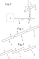
- the contact surfaces S of the conveyors 10, 11, 12 are arranged substantially on a same plane (see figure 4 ), while according to a different configuration, the conveyors 10, 11, 12 are mutually arranged in pairs in such a way that the downstream end of the conveyors further upstream is higher than and overlapping the upstream end of the conveyor further downstream (see figure 5 ).
- the apparatus 1 includes a pressure varying device 2 and the contact surface S of the conveyors 10, 11, 12 has through holes which are designed to be placed in fluid communication with this pressure varying device 2.
- the pressure varying device 2 can include both a negative pressure source and an overpressure source, which can possibly coincide and be defined by a compressor/aspirator, for example, equipped with an impeller or other devices known on the market.
- the adherence of certain articles can be increased by creating a negative pressure at the contact surface S (see the arrows in figures 1 and 3 ), or the adherence of certain articles can be decreased by creating an overpressure at the surface S (see for example figure 2 ), to make it possible, in cooperation with the force of gravity, to more effectively separate the stacked or piled articles.
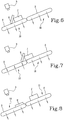
- the adherence of a belt 11 (or another conveyor) which receives an article J from the adjacent belt 10 placed upstream can be increased, to define a gradient of adherence between it and the other articles K of the stack, to favour the unstacking or destacking (see figures 6 and 7 ).
- the adherence of the belt upstream 10 can be decreased during the transfer of one or more articles J on a belt downstream 11, so that the force of gravity favours the downstream sliding, separating the pile.
- Holes can be formed on a majority portion of the mobile contact surface S and, preferably, they are distributed in a uniform manner.
- a perforated box-shaped element is placed which is designed to communicate fluid dynamically with the pressure varying device 2.
- communication ducts 21 can be provided, preferably with the interposition of valves 22 to adjust the fluid communication (see figures 1 - 3 ).
- the apparatus 1 comprises one or more acquisition devices 3, designed to detect the arrangement of the articles J, K moved on one or more of the conveyors 10, 11, 12.
- Each acquisition device 3 which can for example comprise a camera, is designed to produce arrangement signals that depend on the acquired configuration of the articles.
- the apparatus 1 includes a processing unit, connected to the acquisition device 3 and configured to control the operation of the pressure varying device 2 based on the above-mentioned arrangement signals.
- the aspirator/compressor 2 is consequently activated or deactivated or the above-mentioned valves 3 are opened or closed, which are subject to the processing unit.
- the processing unit can control an aspiration on the contact surface S of the belt 11 further downstream, i.e. the one which is higher, which with the aid of the force of gravity, produces a separation of the two articles J, K, especially if the contact surface S of the belt further upstream 10 is air blown.
- a conveying surface is defined along which the articles are moved, which is divided into a plurality of operating areas designed to be selectively positioned in fluid communication with the pressure varying device 2.
- two or more perforated box-shaped elements can be provided inside the belt 10, 11, 12 or the perforated box-shaped structure can be internally compartmentalised by dividers.
- each operational area can be connected to the aspirator/compressor 2 with the interposition of a respective valve 22 controlled by the processing unit.
- the processing unit comprises a position module configured to determine the relative position of the articles on the conveyor surface, as a function of the arrangement signals received from the camera 3 and also comprises a selection module configured in such a way as to select which of said operating areas is put in communication with the pressure varying device 2.
- the processing unit based on the position of the articles J, K on the belt 10, 11, 12, can decide to produce a variation of the surface pressure at a specific area, for example to increase adherence of a specific article placed at the same area and can decrease that of another article stacked on the first, so as to cause the separation thereof.
- the invention in its general aspects, operates as described below.
- the proposed apparatus 1 is fed with loose articles, stacked or piled, at the bottom of the ramp.
- the first belt 10 carries the products J, K upwards, which begin to be subject to the force of gravity.
- an adherence differential is produced, according to the already explained methodologies, so as to separate or otherwise scatter the overlapping articles.
- This operation is repeated several times, in order to have a destacking of the articles so as to eliminate mutual overlapping.
Landscapes
- Engineering & Computer Science (AREA)
- Mechanical Engineering (AREA)
- Delivering By Means Of Belts And Rollers (AREA)
- Structure Of Belt Conveyors (AREA)
- Attitude Control For Articles On Conveyors (AREA)
- Sheets, Magazines, And Separation Thereof (AREA)
- De-Stacking Of Articles (AREA)
- Control Of Conveyors (AREA)
- Sorting Of Articles (AREA)
- Fittings On The Vehicle Exterior For Carrying Loads, And Devices For Holding Or Mounting Articles (AREA)
- Investigating Or Analyzing Materials By The Use Of Ultrasonic Waves (AREA)
- Bridges Or Land Bridges (AREA)
Abstract
Description
- The present invention relates to a perfected destacker apparatus, especially intended for use in sorter systems for leaflets, envelopes, parcels or other articles.
- Destackers are known which are constituted by a series of inclined motorised belts, to define a sort of ramp, at the base of which stacks or piles of articles are fed, which are gripped and carried upwards from the first belt of the series.
- The destacking is performed by exploiting the force of gravity, allowing the groups of articles that are carried upwards to separate when one or more of them slides downwards and exploiting variable speeds or accelerations between two subsequent belts, so that different movement conditions are created between different articles that can promote their separation.
- These known systems operate with a certain efficacy in destacking parcels or other articles that are not very light, but are much less effective when used to separate leaflets or similar.
- In this context, the technical task underpinning the present invention is to propose a destacker apparatus able to overcome the drawbacks of the cited prior art.
- The technical task is reached by the machine realised in accordance with claim 1.
- Further characteristics and advantages of the present invention will become more apparent from the approximate and thus non-limiting description of a preferred, but not exclusive, embodiment of an apparatus of the invention, as illustrated in the accompanying drawings, in which:
-
figures 1 and 2 are schematic views of the apparatus of the invention, showing two modes of operation; -
figure 3 is a schematic view of the apparatus of the preceding claim, in which an adjustment valve is shown; -
figures 4 and 5 are schematic views showing possible configurations of the conveyors of the proposed apparatus; and -
figures 6 - 8 are schematic views showing a sequence of operation of the invention. - With reference to the above-mentioned figures, reference number 1 indicates a destacker apparatus realised according to the invention.
- The proposed apparatus 1 firstly comprises a succession of
conveyors - In practice, the conveyors are arranged at increasing heights, preferably with the same inclination, to define an upwards transport path; for example, three
conveyors - These articles, for example leaflets, but also parcels, envelopes or others, are transported from the bottom of the apparatus 1 towards the top, through subsequent delivery passages between the
various conveyors - The output of the apparatus 1 is at the top of the
ramp - Preferably, the
conveyors belt - According to one possible configuration of the
ramp conveyors figure 4 ), while according to a different configuration, theconveyors figure 5 ). - According to an important aspect of the invention, the apparatus 1 includes a
pressure varying device 2 and the contact surface S of theconveyors pressure varying device 2. - In detail, the pressure
varying device 2 can include both a negative pressure source and an overpressure source, which can possibly coincide and be defined by a compressor/aspirator, for example, equipped with an impeller or other devices known on the market. - Thanks to this expedient, the adherence of certain articles can be increased by creating a negative pressure at the contact surface S (see the arrows in
figures 1 and3 ), or the adherence of certain articles can be decreased by creating an overpressure at the surface S (see for examplefigure 2 ), to make it possible, in cooperation with the force of gravity, to more effectively separate the stacked or piled articles. - For example, the adherence of a belt 11 (or another conveyor) which receives an article J from the
adjacent belt 10 placed upstream can be increased, to define a gradient of adherence between it and the other articles K of the stack, to favour the unstacking or destacking (seefigures 6 and 7 ). - Conversely, the adherence of the belt upstream 10 can be decreased during the transfer of one or more articles J on a belt downstream 11, so that the force of gravity favours the downstream sliding, separating the pile.
- The two modes of use described in the preceding paragraphs can be used together or in a selective manner; moreover, further modes of use will be illustrated in the description of the operation of the invention.
- Holes can be formed on a majority portion of the mobile contact surface S and, preferably, they are distributed in a uniform manner.
- Preferably, inside the
conveyor belts varying device 2. - Even more in detail, between the
pressure varying device 2 and the interior of theconveyors communication ducts 21 can be provided, preferably with the interposition ofvalves 22 to adjust the fluid communication (seefigures 1 - 3 ). - For example, it is possible to select the
conveyors respective adjustment valve 22 for each of them. - According to an important aspect of the invention, the apparatus 1 comprises one or
more acquisition devices 3, designed to detect the arrangement of the articles J, K moved on one or more of theconveyors - Each
acquisition device 3, which can for example comprise a camera, is designed to produce arrangement signals that depend on the acquired configuration of the articles. - Furthermore, the apparatus 1 includes a processing unit, connected to the
acquisition device 3 and configured to control the operation of the pressurevarying device 2 based on the above-mentioned arrangement signals. - In practice, based on the fact that the camera 3 (or other device designed for the purpose) detects individual or stacked articles, the aspirator/
compressor 2 is consequently activated or deactivated or the above-mentionedvalves 3 are opened or closed, which are subject to the processing unit. - For example, as shown in
figures 6 - 8 , if thecamera 3 detects a group of two stacked articles J, K, the processing unit can control an aspiration on the contact surface S of thebelt 11 further downstream, i.e. the one which is higher, which with the aid of the force of gravity, produces a separation of the two articles J, K, especially if the contact surface S of the belt further upstream 10 is air blown. - Once the separation has been performed, the adherence on both
belts - According to a particular embodiment of the invention, at the contact surface S of each
conveyors varying device 2. - In practice, multiple zones or quadrants are identified on the upper branch of the
belt - For example, two or more perforated box-shaped elements can be provided inside the
belt - In any case, each operational area can be connected to the aspirator/
compressor 2 with the interposition of arespective valve 22 controlled by the processing unit. - In detail, the processing unit comprises a position module configured to determine the relative position of the articles on the conveyor surface, as a function of the arrangement signals received from the
camera 3 and also comprises a selection module configured in such a way as to select which of said operating areas is put in communication with the pressurevarying device 2. - In other words, the processing unit, based on the position of the articles J, K on the
belt - The invention, in its general aspects, operates as described below.
- The proposed apparatus 1 is fed with loose articles, stacked or piled, at the bottom of the ramp.
- The
first belt 10 carries the products J, K upwards, which begin to be subject to the force of gravity. - Particularly at the transition zones of the
belts - This operation is repeated several times, in order to have a destacking of the articles so as to eliminate mutual overlapping.
- It can thus be understood how the invention is capable of effectively destacking also leaflets or other very light articles, thus overcoming the limitations of the prior art.
Claims (10)
- A destacker apparatus (1), comprising:a succession of conveyors (10, 11, 12) arranged inclined relative to the horizon, each comprising a mobile surface (S) for receiving and supporting articles (J, K) carried upwards by the conveyors (10, 11, 12); andat least one device for varying the pressure of a fluid (2);wherein the surface (S) of at least one of the conveyors (10, 11, 12) has through holes and wherein the pressure varying device (2) is fluid dynamically connectable to the surface (S).
- The apparatus (1) according to the preceding claim, wherein the holes are distributed on a majority portion of the mobile surface (S).
- The apparatus according to any one of the preceding claims, wherein the conveyors (10, 11, 12) each comprise a conveyor belt closed in a loop around end drives, equipped with a contact surface (S) defined by the upper ramp of the belt.
- The apparatus (1) according to the preceding claim, comprising, in one or more belts (10, 11, 12) a perforated box-shaped element designed to communicate fluid dynamically with the pressure varying device (2).
- The apparatus (1) according to any one of the preceding claims, wherein the contact surfaces (S) of two or more conveyors (10, 11, 12) are positioned substantially on a same plane.
- The apparatus (1) according to any one of the preceding claims, wherein at least one pair of conveyors (10, 11, 12) is mutually positioned in such a way that the downstream end of the conveyor further upstream is higher than the upstream end of the conveyor downstream.
- The apparatus (1) according to any one of the preceding claims, wherein the pressure varying device (2) is designed to produce a negative pressure.
- The apparatus (1) according to any one of the preceding claims, wherein the pressure varying device (2) is designed to produce an overpressure.
- The apparatus (1) according to any one of the preceding claims, comprising:at least one acquisition device (3) designed to detect the arrangement of the articles (J, K) moved on at least one conveyor (10, 11, 12) and to produce arrangement signals; andat least one processing unit connected to the acquisition device (3) and configured to control the operation of the pressure varying device (2) according to the arrangement signals.
- The apparatus (1) according to the preceding claim, wherein the contact surface (S) defines a conveying surface along which the articles are moved, divided into a plurality of operating areas designed to be selectively positioned in fluid communication with the pressure varying device (2), the processing unit comprising a position module for determining the relative position of the articles (J, K) on the conveyor surface, as a function of the arrangement signals and a selection module configured in such a way as to select which of the operating areas is put in fluid communication with the pressure varying device (2), as a function of the position signals.
Applications Claiming Priority (1)
| Application Number | Priority Date | Filing Date | Title |
|---|---|---|---|
| IT102018000007630A IT201800007630A1 (en) | 2018-07-30 | 2018-07-30 | Singularizing apparatus. |
Publications (2)
| Publication Number | Publication Date |
|---|---|
| EP3604181A1 true EP3604181A1 (en) | 2020-02-05 |
| EP3604181B1 EP3604181B1 (en) | 2021-09-01 |
Family
ID=64049529
Family Applications (1)
| Application Number | Title | Priority Date | Filing Date |
|---|---|---|---|
| EP19184597.3A Active EP3604181B1 (en) | 2018-07-30 | 2019-07-05 | A destacker apparatus |
Country Status (9)
| Country | Link |
|---|---|
| US (1) | US10865056B2 (en) |
| EP (1) | EP3604181B1 (en) |
| JP (1) | JP7161454B2 (en) |
| KR (1) | KR102470017B1 (en) |
| CN (1) | CN110775669B (en) |
| AU (1) | AU2019204996A1 (en) |
| BR (1) | BR102019015448A2 (en) |
| CA (1) | CA3048826C (en) |
| IT (1) | IT201800007630A1 (en) |
Families Citing this family (1)
| Publication number | Priority date | Publication date | Assignee | Title |
|---|---|---|---|---|
| CN114572662A (en) * | 2022-02-17 | 2022-06-03 | 浙江华睿科技股份有限公司 | Package separation method and device and readable storage medium |
Citations (4)
| Publication number | Priority date | Publication date | Assignee | Title |
|---|---|---|---|---|
| US3291282A (en) * | 1965-06-10 | 1966-12-13 | Antonio D Pedagno | Mail feeding equipment |
| JPH08169553A (en) * | 1994-12-16 | 1996-07-02 | Sumitomo Heavy Ind Ltd | Automatic supply device of book |
| DE102013212423A1 (en) * | 2013-06-27 | 2014-12-31 | Siemens Aktiengesellschaft | Device and method for stripping and conveying objects arranged in stacks |
| US20150158672A1 (en) * | 2013-12-05 | 2015-06-11 | The Procter & Gamble Company | Apparatus and Method for Conveying Absorbent Articles |
Family Cites Families (12)
| Publication number | Priority date | Publication date | Assignee | Title |
|---|---|---|---|---|
| JPS54115870A (en) * | 1978-02-27 | 1979-09-08 | Masaharu Matsuo | Belt paper feeder |
| US4359214A (en) * | 1980-12-22 | 1982-11-16 | Paxall, Inc. | Apparatus for feeding flat articles |
| JPS63162716U (en) * | 1987-04-09 | 1988-10-24 | ||
| US5074539A (en) * | 1990-09-11 | 1991-12-24 | Ward Holding Company, Inc. | Feeding sheets of corrugated paperboard |
| IT1257920B (en) * | 1992-11-27 | 1996-02-19 | FLOW COMPENSATION DEVICE FOR POSTAL OBJECTS. | |
| US6491154B2 (en) * | 2000-12-26 | 2002-12-10 | Sandvik Sorting Systems, Inc. | Unstacker for unstacking items conveyed in a bulk stream |
| US7100422B2 (en) * | 2002-05-31 | 2006-09-05 | Drs Sustainment Systems, Inc. | Systems and methods for residue collection with improved letter handling capability |
| DE10229322A1 (en) * | 2002-06-29 | 2004-01-15 | Kolbus Gmbh & Co. Kg | Device for separating a shingled stream of printed products into a sequence of spaced-apart printed products |
| DE102007024945A1 (en) * | 2006-06-06 | 2007-12-13 | Eastman Kodak Co. | Sheet transporting method for use in e.g. inkjet printer, involves applying electrical charges in area within which sheet is sucked into rotating conveyor for generating electrostatic retention force between rotating conveyor and sheet |
| US7607533B2 (en) * | 2008-03-14 | 2009-10-27 | Laitram, L.L.C. | Conveyors and methods for non-uniformly accelerating conveyed articles |
| JP2013537872A (en) * | 2010-09-27 | 2013-10-07 | オセ−テクノロジーズ ビーブイ | Printing system having sheet conveying device |
| US9498798B2 (en) * | 2015-01-16 | 2016-11-22 | Carefusion Germany 326 Gmbh | Piece goods separating apparatus |
-
2018
- 2018-07-30 IT IT102018000007630A patent/IT201800007630A1/en unknown
-
2019
- 2019-07-05 EP EP19184597.3A patent/EP3604181B1/en active Active
- 2019-07-08 CA CA3048826A patent/CA3048826C/en active Active
- 2019-07-11 AU AU2019204996A patent/AU2019204996A1/en active Pending
- 2019-07-17 US US16/514,603 patent/US10865056B2/en active Active
- 2019-07-26 BR BR102019015448-9A patent/BR102019015448A2/en unknown
- 2019-07-26 JP JP2019138134A patent/JP7161454B2/en active Active
- 2019-07-26 KR KR1020190090776A patent/KR102470017B1/en active IP Right Grant
- 2019-07-26 CN CN201910682984.9A patent/CN110775669B/en active Active
Patent Citations (4)
| Publication number | Priority date | Publication date | Assignee | Title |
|---|---|---|---|---|
| US3291282A (en) * | 1965-06-10 | 1966-12-13 | Antonio D Pedagno | Mail feeding equipment |
| JPH08169553A (en) * | 1994-12-16 | 1996-07-02 | Sumitomo Heavy Ind Ltd | Automatic supply device of book |
| DE102013212423A1 (en) * | 2013-06-27 | 2014-12-31 | Siemens Aktiengesellschaft | Device and method for stripping and conveying objects arranged in stacks |
| US20150158672A1 (en) * | 2013-12-05 | 2015-06-11 | The Procter & Gamble Company | Apparatus and Method for Conveying Absorbent Articles |
Also Published As
| Publication number | Publication date |
|---|---|
| KR102470017B1 (en) | 2022-11-22 |
| US10865056B2 (en) | 2020-12-15 |
| CA3048826C (en) | 2023-03-14 |
| US20200031595A1 (en) | 2020-01-30 |
| AU2019204996A1 (en) | 2020-02-13 |
| JP2020019653A (en) | 2020-02-06 |
| CN110775669A (en) | 2020-02-11 |
| IT201800007630A1 (en) | 2020-01-30 |
| CA3048826A1 (en) | 2020-01-30 |
| JP7161454B2 (en) | 2022-10-26 |
| BR102019015448A2 (en) | 2020-02-11 |
| CN110775669B (en) | 2022-08-05 |
| KR20200013608A (en) | 2020-02-07 |
| EP3604181B1 (en) | 2021-09-01 |
Similar Documents
| Publication | Publication Date | Title |
|---|---|---|
| US9878349B2 (en) | Postal sorting machine with a feed inlet having a robotized arm and a sloping flat conveyor | |
| US10358298B2 (en) | Slide sorter pop-up diverting conveyor with transfer rate based on article characteristics | |
| US10166575B2 (en) | Shift and hold conveyor assembly for removal of oversize parcels | |
| US20160263622A1 (en) | Postal Sorting Machine With a Feed Inlet Having a Robotized Arm and a Vertically Movable Magazine | |
| US6259967B1 (en) | Parcel singulation system | |
| EP3060504B1 (en) | Singulator conveying system for rigid parcels and large bags of small parcels | |
| US6609607B2 (en) | Article separation conveyor | |
| CN107777275B (en) | Transport system and method for transporting piece goods on a transport path of a transport system | |
| US10501269B2 (en) | Singulation of parcels | |
| JP2004516210A (en) | Downward inclined loading / unloading apparatus and method for loading / unloading stacked articles | |
| US20170173635A1 (en) | Stepped wall singulator conveyor for oversized item removal | |
| EP3604181B1 (en) | A destacker apparatus | |
| US3941370A (en) | Sheet glass - conveying, classifying and stacking apparatus | |
| JP2009091023A (en) | Feeder of leaf-shaped agricultural product | |
| US6564922B1 (en) | Flex diverter | |
| US20240002164A1 (en) | Apparatus for Orienting or Rotating Objects | |
| EP4173999A1 (en) | System for conveying products | |
| US20240002169A1 (en) | Apparatus for Conveying Objects | |
| US20240002170A1 (en) | Apparatus for Orienting or Rotating Objects | |
| US20240002165A1 (en) | Apparatus for Orienting or Rotating Objects | |
| RU2611147C1 (en) | Sheets extraction device and sheets processing device |
Legal Events
| Date | Code | Title | Description |
|---|---|---|---|
| PUAI | Public reference made under article 153(3) epc to a published international application that has entered the european phase |
Free format text: ORIGINAL CODE: 0009012 |
|
| STAA | Information on the status of an ep patent application or granted ep patent |
Free format text: STATUS: THE APPLICATION HAS BEEN PUBLISHED |
|
| AK | Designated contracting states |
Kind code of ref document: A1 Designated state(s): AL AT BE BG CH CY CZ DE DK EE ES FI FR GB GR HR HU IE IS IT LI LT LU LV MC MK MT NL NO PL PT RO RS SE SI SK SM TR |
|
| AX | Request for extension of the european patent |
Extension state: BA ME |
|
| STAA | Information on the status of an ep patent application or granted ep patent |
Free format text: STATUS: REQUEST FOR EXAMINATION WAS MADE |
|
| 17P | Request for examination filed |
Effective date: 20200731 |
|
| RBV | Designated contracting states (corrected) |
Designated state(s): AL AT BE BG CH CY CZ DE DK EE ES FI FR GB GR HR HU IE IS IT LI LT LU LV MC MK MT NL NO PL PT RO RS SE SI SK SM TR |
|
| GRAP | Despatch of communication of intention to grant a patent |
Free format text: ORIGINAL CODE: EPIDOSNIGR1 |
|
| STAA | Information on the status of an ep patent application or granted ep patent |
Free format text: STATUS: GRANT OF PATENT IS INTENDED |
|
| INTG | Intention to grant announced |
Effective date: 20210507 |
|
| RIC1 | Information provided on ipc code assigned before grant |
Ipc: B07C 1/04 20060101ALI20210423BHEP Ipc: B65G 21/20 20060101ALI20210423BHEP Ipc: B65G 47/30 20060101AFI20210423BHEP |
|
| GRAS | Grant fee paid |
Free format text: ORIGINAL CODE: EPIDOSNIGR3 |
|
| GRAA | (expected) grant |
Free format text: ORIGINAL CODE: 0009210 |
|
| STAA | Information on the status of an ep patent application or granted ep patent |
Free format text: STATUS: THE PATENT HAS BEEN GRANTED |
|
| AK | Designated contracting states |
Kind code of ref document: B1 Designated state(s): AL AT BE BG CH CY CZ DE DK EE ES FI FR GB GR HR HU IE IS IT LI LT LU LV MC MK MT NL NO PL PT RO RS SE SI SK SM TR |
|
| REG | Reference to a national code |
Ref country code: GB Ref legal event code: FG4D |
|
| REG | Reference to a national code |
Ref country code: CH Ref legal event code: EP Ref country code: AT Ref legal event code: REF Ref document number: 1426045 Country of ref document: AT Kind code of ref document: T Effective date: 20210915 |
|
| REG | Reference to a national code |
Ref country code: DE Ref legal event code: R096 Ref document number: 602019007291 Country of ref document: DE |
|
| REG | Reference to a national code |
Ref country code: IE Ref legal event code: FG4D |
|
| REG | Reference to a national code |
Ref country code: SE Ref legal event code: TRGR |
|
| REG | Reference to a national code |
Ref country code: LT Ref legal event code: MG9D |
|
| REG | Reference to a national code |
Ref country code: NL Ref legal event code: MP Effective date: 20210901 |
|
| PG25 | Lapsed in a contracting state [announced via postgrant information from national office to epo] |
Ref country code: LT Free format text: LAPSE BECAUSE OF FAILURE TO SUBMIT A TRANSLATION OF THE DESCRIPTION OR TO PAY THE FEE WITHIN THE PRESCRIBED TIME-LIMIT Effective date: 20210901 Ref country code: BG Free format text: LAPSE BECAUSE OF FAILURE TO SUBMIT A TRANSLATION OF THE DESCRIPTION OR TO PAY THE FEE WITHIN THE PRESCRIBED TIME-LIMIT Effective date: 20211201 Ref country code: HR Free format text: LAPSE BECAUSE OF FAILURE TO SUBMIT A TRANSLATION OF THE DESCRIPTION OR TO PAY THE FEE WITHIN THE PRESCRIBED TIME-LIMIT Effective date: 20210901 Ref country code: NO Free format text: LAPSE BECAUSE OF FAILURE TO SUBMIT A TRANSLATION OF THE DESCRIPTION OR TO PAY THE FEE WITHIN THE PRESCRIBED TIME-LIMIT Effective date: 20211201 Ref country code: RS Free format text: LAPSE BECAUSE OF FAILURE TO SUBMIT A TRANSLATION OF THE DESCRIPTION OR TO PAY THE FEE WITHIN THE PRESCRIBED TIME-LIMIT Effective date: 20210901 Ref country code: FI Free format text: LAPSE BECAUSE OF FAILURE TO SUBMIT A TRANSLATION OF THE DESCRIPTION OR TO PAY THE FEE WITHIN THE PRESCRIBED TIME-LIMIT Effective date: 20210901 Ref country code: ES Free format text: LAPSE BECAUSE OF FAILURE TO SUBMIT A TRANSLATION OF THE DESCRIPTION OR TO PAY THE FEE WITHIN THE PRESCRIBED TIME-LIMIT Effective date: 20210901 |
|
| REG | Reference to a national code |
Ref country code: AT Ref legal event code: MK05 Ref document number: 1426045 Country of ref document: AT Kind code of ref document: T Effective date: 20210901 |
|
| PG25 | Lapsed in a contracting state [announced via postgrant information from national office to epo] |
Ref country code: PL Free format text: LAPSE BECAUSE OF FAILURE TO SUBMIT A TRANSLATION OF THE DESCRIPTION OR TO PAY THE FEE WITHIN THE PRESCRIBED TIME-LIMIT Effective date: 20210901 Ref country code: LV Free format text: LAPSE BECAUSE OF FAILURE TO SUBMIT A TRANSLATION OF THE DESCRIPTION OR TO PAY THE FEE WITHIN THE PRESCRIBED TIME-LIMIT Effective date: 20210901 Ref country code: GR Free format text: LAPSE BECAUSE OF FAILURE TO SUBMIT A TRANSLATION OF THE DESCRIPTION OR TO PAY THE FEE WITHIN THE PRESCRIBED TIME-LIMIT Effective date: 20211202 |
|
| PG25 | Lapsed in a contracting state [announced via postgrant information from national office to epo] |
Ref country code: AT Free format text: LAPSE BECAUSE OF FAILURE TO SUBMIT A TRANSLATION OF THE DESCRIPTION OR TO PAY THE FEE WITHIN THE PRESCRIBED TIME-LIMIT Effective date: 20210901 |
|
| PG25 | Lapsed in a contracting state [announced via postgrant information from national office to epo] |
Ref country code: IS Free format text: LAPSE BECAUSE OF FAILURE TO SUBMIT A TRANSLATION OF THE DESCRIPTION OR TO PAY THE FEE WITHIN THE PRESCRIBED TIME-LIMIT Effective date: 20220101 Ref country code: SM Free format text: LAPSE BECAUSE OF FAILURE TO SUBMIT A TRANSLATION OF THE DESCRIPTION OR TO PAY THE FEE WITHIN THE PRESCRIBED TIME-LIMIT Effective date: 20210901 Ref country code: SK Free format text: LAPSE BECAUSE OF FAILURE TO SUBMIT A TRANSLATION OF THE DESCRIPTION OR TO PAY THE FEE WITHIN THE PRESCRIBED TIME-LIMIT Effective date: 20210901 Ref country code: RO Free format text: LAPSE BECAUSE OF FAILURE TO SUBMIT A TRANSLATION OF THE DESCRIPTION OR TO PAY THE FEE WITHIN THE PRESCRIBED TIME-LIMIT Effective date: 20210901 Ref country code: PT Free format text: LAPSE BECAUSE OF FAILURE TO SUBMIT A TRANSLATION OF THE DESCRIPTION OR TO PAY THE FEE WITHIN THE PRESCRIBED TIME-LIMIT Effective date: 20220103 Ref country code: NL Free format text: LAPSE BECAUSE OF FAILURE TO SUBMIT A TRANSLATION OF THE DESCRIPTION OR TO PAY THE FEE WITHIN THE PRESCRIBED TIME-LIMIT Effective date: 20210901 Ref country code: EE Free format text: LAPSE BECAUSE OF FAILURE TO SUBMIT A TRANSLATION OF THE DESCRIPTION OR TO PAY THE FEE WITHIN THE PRESCRIBED TIME-LIMIT Effective date: 20210901 Ref country code: CZ Free format text: LAPSE BECAUSE OF FAILURE TO SUBMIT A TRANSLATION OF THE DESCRIPTION OR TO PAY THE FEE WITHIN THE PRESCRIBED TIME-LIMIT Effective date: 20210901 Ref country code: AL Free format text: LAPSE BECAUSE OF FAILURE TO SUBMIT A TRANSLATION OF THE DESCRIPTION OR TO PAY THE FEE WITHIN THE PRESCRIBED TIME-LIMIT Effective date: 20210901 |
|
| REG | Reference to a national code |
Ref country code: DE Ref legal event code: R097 Ref document number: 602019007291 Country of ref document: DE |
|
| PLBE | No opposition filed within time limit |
Free format text: ORIGINAL CODE: 0009261 |
|
| STAA | Information on the status of an ep patent application or granted ep patent |
Free format text: STATUS: NO OPPOSITION FILED WITHIN TIME LIMIT |
|
| PG25 | Lapsed in a contracting state [announced via postgrant information from national office to epo] |
Ref country code: DK Free format text: LAPSE BECAUSE OF FAILURE TO SUBMIT A TRANSLATION OF THE DESCRIPTION OR TO PAY THE FEE WITHIN THE PRESCRIBED TIME-LIMIT Effective date: 20210901 |
|
| 26N | No opposition filed |
Effective date: 20220602 |
|
| PG25 | Lapsed in a contracting state [announced via postgrant information from national office to epo] |
Ref country code: SI Free format text: LAPSE BECAUSE OF FAILURE TO SUBMIT A TRANSLATION OF THE DESCRIPTION OR TO PAY THE FEE WITHIN THE PRESCRIBED TIME-LIMIT Effective date: 20210901 |
|
| PG25 | Lapsed in a contracting state [announced via postgrant information from national office to epo] |
Ref country code: MC Free format text: LAPSE BECAUSE OF FAILURE TO SUBMIT A TRANSLATION OF THE DESCRIPTION OR TO PAY THE FEE WITHIN THE PRESCRIBED TIME-LIMIT Effective date: 20210901 |
|
| REG | Reference to a national code |
Ref country code: CH Ref legal event code: PL |
|
| REG | Reference to a national code |
Ref country code: BE Ref legal event code: MM Effective date: 20220731 |
|
| PG25 | Lapsed in a contracting state [announced via postgrant information from national office to epo] |
Ref country code: LU Free format text: LAPSE BECAUSE OF NON-PAYMENT OF DUE FEES Effective date: 20220705 Ref country code: LI Free format text: LAPSE BECAUSE OF NON-PAYMENT OF DUE FEES Effective date: 20220731 Ref country code: CH Free format text: LAPSE BECAUSE OF NON-PAYMENT OF DUE FEES Effective date: 20220731 |
|
| PG25 | Lapsed in a contracting state [announced via postgrant information from national office to epo] |
Ref country code: BE Free format text: LAPSE BECAUSE OF NON-PAYMENT OF DUE FEES Effective date: 20220731 |
|
| P01 | Opt-out of the competence of the unified patent court (upc) registered |
Effective date: 20230529 |
|
| PG25 | Lapsed in a contracting state [announced via postgrant information from national office to epo] |
Ref country code: IE Free format text: LAPSE BECAUSE OF NON-PAYMENT OF DUE FEES Effective date: 20220705 |
|
| PGFP | Annual fee paid to national office [announced via postgrant information from national office to epo] |
Ref country code: IT Payment date: 20230620 Year of fee payment: 5 Ref country code: FR Payment date: 20230621 Year of fee payment: 5 |
|
| PGFP | Annual fee paid to national office [announced via postgrant information from national office to epo] |
Ref country code: SE Payment date: 20230622 Year of fee payment: 5 |
|
| PGFP | Annual fee paid to national office [announced via postgrant information from national office to epo] |
Ref country code: GB Payment date: 20230620 Year of fee payment: 5 |
|
| PGFP | Annual fee paid to national office [announced via postgrant information from national office to epo] |
Ref country code: DE Payment date: 20230620 Year of fee payment: 5 |
|
| PG25 | Lapsed in a contracting state [announced via postgrant information from national office to epo] |
Ref country code: HU Free format text: LAPSE BECAUSE OF FAILURE TO SUBMIT A TRANSLATION OF THE DESCRIPTION OR TO PAY THE FEE WITHIN THE PRESCRIBED TIME-LIMIT; INVALID AB INITIO Effective date: 20190705 |
|
| PG25 | Lapsed in a contracting state [announced via postgrant information from national office to epo] |
Ref country code: MK Free format text: LAPSE BECAUSE OF FAILURE TO SUBMIT A TRANSLATION OF THE DESCRIPTION OR TO PAY THE FEE WITHIN THE PRESCRIBED TIME-LIMIT Effective date: 20210901 Ref country code: CY Free format text: LAPSE BECAUSE OF FAILURE TO SUBMIT A TRANSLATION OF THE DESCRIPTION OR TO PAY THE FEE WITHIN THE PRESCRIBED TIME-LIMIT Effective date: 20210901 |