EP3604056A1 - Power brake valve - Google Patents
Power brake valve Download PDFInfo
- Publication number
- EP3604056A1 EP3604056A1 EP19186245.7A EP19186245A EP3604056A1 EP 3604056 A1 EP3604056 A1 EP 3604056A1 EP 19186245 A EP19186245 A EP 19186245A EP 3604056 A1 EP3604056 A1 EP 3604056A1
- Authority
- EP
- European Patent Office
- Prior art keywords
- pressure
- brake valve
- power brake
- fluid
- source
- Prior art date
- Legal status (The legal status is an assumption and is not a legal conclusion. Google has not performed a legal analysis and makes no representation as to the accuracy of the status listed.)
- Granted
Links
- 239000012530 fluid Substances 0.000 claims abstract description 64
- 230000001105 regulatory effect Effects 0.000 claims description 5
- 230000003247 decreasing effect Effects 0.000 description 3
- 230000004048 modification Effects 0.000 description 1
- 238000012986 modification Methods 0.000 description 1
Images


Classifications
-
- B—PERFORMING OPERATIONS; TRANSPORTING
- B60—VEHICLES IN GENERAL
- B60T—VEHICLE BRAKE CONTROL SYSTEMS OR PARTS THEREOF; BRAKE CONTROL SYSTEMS OR PARTS THEREOF, IN GENERAL; ARRANGEMENT OF BRAKING ELEMENTS ON VEHICLES IN GENERAL; PORTABLE DEVICES FOR PREVENTING UNWANTED MOVEMENT OF VEHICLES; VEHICLE MODIFICATIONS TO FACILITATE COOLING OF BRAKES
- B60T11/00—Transmitting braking action from initiating means to ultimate brake actuator without power assistance or drive or where such assistance or drive is irrelevant
- B60T11/10—Transmitting braking action from initiating means to ultimate brake actuator without power assistance or drive or where such assistance or drive is irrelevant transmitting by fluid means, e.g. hydraulic
- B60T11/16—Master control, e.g. master cylinders
- B60T11/20—Tandem, side-by-side, or other multiple master cylinder units
- B60T11/21—Tandem, side-by-side, or other multiple master cylinder units with two pedals operating on respective circuits, pressures therein being equalised when both pedals are operated together, e.g. for steering
-
- B—PERFORMING OPERATIONS; TRANSPORTING
- B62—LAND VEHICLES FOR TRAVELLING OTHERWISE THAN ON RAILS
- B62D—MOTOR VEHICLES; TRAILERS
- B62D11/00—Steering non-deflectable wheels; Steering endless tracks or the like
- B62D11/02—Steering non-deflectable wheels; Steering endless tracks or the like by differentially driving ground-engaging elements on opposite vehicle sides
- B62D11/06—Steering non-deflectable wheels; Steering endless tracks or the like by differentially driving ground-engaging elements on opposite vehicle sides by means of a single main power source
- B62D11/08—Steering non-deflectable wheels; Steering endless tracks or the like by differentially driving ground-engaging elements on opposite vehicle sides by means of a single main power source using brakes or clutches as main steering-effecting means
-
- B—PERFORMING OPERATIONS; TRANSPORTING
- B60—VEHICLES IN GENERAL
- B60T—VEHICLE BRAKE CONTROL SYSTEMS OR PARTS THEREOF; BRAKE CONTROL SYSTEMS OR PARTS THEREOF, IN GENERAL; ARRANGEMENT OF BRAKING ELEMENTS ON VEHICLES IN GENERAL; PORTABLE DEVICES FOR PREVENTING UNWANTED MOVEMENT OF VEHICLES; VEHICLE MODIFICATIONS TO FACILITATE COOLING OF BRAKES
- B60T8/00—Arrangements for adjusting wheel-braking force to meet varying vehicular or ground-surface conditions, e.g. limiting or varying distribution of braking force
- B60T8/26—Arrangements for adjusting wheel-braking force to meet varying vehicular or ground-surface conditions, e.g. limiting or varying distribution of braking force characterised by producing differential braking between front and rear wheels
Definitions
- the present invention concerns a power brake valve, in particular a power brake valve for a work vehicle, such as an agricultural vehicle.
- Work vehicles e.g. an agricultural vehicle such as a tractor, comprise rear and front brakes configured to impart a braking torque to rear and front axles to stop the vehicle in a predefined time and/or length.
- front wheel hubs have a diameter which is consequently smaller than the one of rear wheel; in view of the preceding, front brakes are of reduced dimensions. Therefore, in order to increase braking torque on front wheels it is necessary to increase the pressure of braking fluid since brakes dimensions cannot be increased.
- agricultural vehicles are constantly improved to allow reaching a higher travel speed e.g. reaching 60 km/h; thus, it is further necessary to increase the capability of front brake which need to impart about 40-50% of the total brake torque imparted to the vehicle. Since such capability cannot be increased by increasing front brake dimensions because of the above limitations, it is necessary to further increase fluid brake pressure.
- An aim of the present invention is to satisfy the above mentioned needs.
- Figures 1 to 4 disclose a hydraulic braking arrangement 1 for a work vehicle comprising a pair of front brakes 2 and rear brakes 3, in particular a right and left front brakes 2a, 2b and right and left rear brakes 3a, 3b.
- hydraulic braking arrangement 1 further comprises a power brake valve 5 fluidly interposed between a common source 4 of fluid in pressure and front and rear brakes 2, 3, power brake valve 5 is configured to receive the fluid at a predefined pressure level from source 4 and to allow the passage of such fluid at a least one different pressure level with respect to the predefined pressure level of source 4 to at least one of brakes 2a, 2b, 3a, 3b.
- source 4 is configured to provide fluid in pressure, e.g. oil, at a pressure of about 100-120 bar and power brake valve 5 is configured to allows passage of such fluid to front brakes 2 at the same pressure of source 4, considering the physical pressure drops in between, and to rear brakes 3 at a pressure which can vary from 10% to 100% of such front value.
- fluid in pressure e.g. oil
- power brake valve 5 is configured to allows passage of such fluid to front brakes 2 at the same pressure of source 4, considering the physical pressure drops in between, and to rear brakes 3 at a pressure which can vary from 10% to 100% of such front value.
- Power brake valve 5 preferably comprises at least a first opening 6, preferably two openings 6a, 6b fluidly connected to left and right front brakes 2a, 2b via respective conduits 8a, 8b or 9a, 9b, at least a second opening 7, preferably two openings 7a, 7b fluidly connected to left and right rear brakes 3a, 3b via respective conduits 9a, 9b or 8a, 8b and at least a third opening 11 fluidly connected to source 4.
- conduits 8a and 8b for fluidly connecting power brake module 5 to front brakes 2a, 2b may be connected together with a logic module 12, e.g. comprising a logic valve 13.
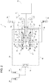
- Figure 1 discloses a power brake valve 5 and the related hydraulic braking arrangement 1 according to a first embodiment of the invention in which source 4 comprises a first and a second accumulators 14', 14" fluidly connected to respective openings 11', 11" to power brake module 5 via conduits 15', 15".
- Source 4 may further comprise a accumulator charging module 16 configured to keep accumulators 14', 14" in determined working conditions.
- power brake valve 5 comprises a first spool 20 fluidly interposed between source 4, first accumulator 14', and openings 6a, 7a and configured to allow passage of fluid in pressure from first accumulator 14' towards right brakes 2a, 3a.
- first spool 20 comprises a first stage 21 defining three ways and two positions, being fluidly connected to opening 11' via a conduit 22, to opening 7a via a conduit 23 and to a discharge 25 via a system of conduits 24.
- First spool 20 further comprises a second stage 27, linked to first stage 21, defining three ways and two positions, being fluidly connected to opening 6a via a conduit 28, to conduit 23 via a conduit 29 and to a discharge 25 via the system of conduits 24.
- Power brake valve 5 further comprises a second spool 20' fluidly interposed between source 4, second accumulator 14", and openings 6b, 7b and configured to allow passage of fluid in pressure from second accumulator 14" towards left brakes 2b, 3b.
- second spool 20' comprises a first stage 21' defining three ways and two positions, being fluidly connected to opening 11" via a conduit 22', to opening 7b via a conduit 23' and to a discharge 25 via a system of conduits 24.
- Second spool 20' further comprises a second stage 27' linked to first stage 21', defining three ways and two positions, being fluidly connected to opening 6b via a conduit 28', to conduit 23' via a conduit 29' and to a discharge 25 via the aforementioned system of conduits 24.
- first and second spool 20, 20' are fluidly connected together to discharge 25 via system of conduits 24.
- Each spool 20, 20' is actuated by a mechanical control input, e.g. given by a respective pedal 31, 31'in known way.
- Power brake valve 5 further comprises pressure variation means 32, 32' fluidly interposed, respectively, on conduits 23, 23' between first stage 21 of first spool 20 and opening 7a and first stage 21' of second spool 20' and opening 7b.
- Pressure variation means 32, 32' are configured to vary the pressure of the fluid passing through them between an inlet and an outlet of these latter.
- pressure variation means 32, 32' are configured to reduce such pressure of at least at 10% of its value.
- pressure variation means 32, 32' are configured to reduce the pressure of fluid passing from conduits 23, 23' to openings 7a, 7b so as to provide a braking fluid to rear brakes 3a, 3b at a pressure lower than the pressure of fluid provided to front brakes 2a, 2b.
- Pressure variation means 32, 32' may allow a fixed ratio of reduction of pressure or a variable ratio of reduction of pressure. Such fixed or variable ratio can be regulated mechanically or electronically in known way.
- pressure variation means 32, 32' may comprise pressure reducing valve 33, 33', e.g. a compensated orifice.
- pressure reducing valve 33, 33' e.g. a compensated orifice.
- compensated orifice may be manually or electrically (e.g. by solenoid) regulated.
- spools 20, 20' are positioned so that they do not allow the passage of fluid from accumulators 11, 11' towards brakes 2, 3; indeed residual fluid present in conduits 9a, 23,9b, 23', 8a, 28, 8b and 28' may flow to discharge 25 via conduits system 24.
- Figure 2 discloses a power brake valve 5 and the related hydraulic braking arrangement 1 according to a second embodiment of the invention in which source 4 comprises a first and a second accumulators 14', 14" fluidly connected to respective openings 11', 11" to power brake module 5 via conduits 15', 15".
- Source 4 may further comprises a accumulator charging module 16' configured to keep accumulators 14', 14" in wanted working conditions.
- power brake valve 5 comprises a first spool 20 fluidly interposed between source 4, first accumulator 14', and openings 6a, 7a and configured to allow passage of fluid in pressure from first accumulator 14' towards right brakes 2a, 3a.
- first spool 20 comprises a first stage 21 defining three ways and two positions, being fluidly connected to opening 11' via a conduit 22, to opening 7a via a conduit 23 and to a discharge 25 via a system of conduits 24.
- Power brake valve 5 further comprises a second spool 20' fluidly interposed between source 4, second accumulator 14", and openings 6b, 7b and configured to allow passage of fluid in pressure from second accumulator 14" towards left brakes 2b, 3b.
- second spool 20' comprises a first stage 21' defining three ways and two positions, being fluidly connected to opening 11" via a conduit 22', to opening 7b via a conduit 23' and to a discharge 25 via a system of conduits 24.
- First spool 20 further comprises a second stage 27, linked by one side to first stage 21, defining three ways and two positions, being fluidly connected to opening 6a via a conduit 28, to conduit 23' of second spool 20' via a conduit 29 and to a discharge 25 via the aforementioned system of conduits 24.
- Second spool 20' further comprises a second stage 27', linked by one side to first stage 21', defining three ways and two positions, being fluidly connected to opening 6b via a conduit 28', to conduit 23 of first spool 20 via a conduit 29' and to a discharge 25 via the aforementioned system of conduits 24.
- first and second spool 20, 20' are fluidly connected together to discharge 25 via system of conduits 24 and by conduits 28, 28' which fluidically link together second stages 27, 27' with respectively conduits 23, 23' of the opposite spool 20, 20'.
- Each spool 20, 20' is driven by a mechanical control input, e.g. given by a respective pedal 31, 31'in known way.
- Power brake valve 5 further comprises pressure variation means 32, 32' integrated, respectively, on conduits second stages 27, 27' of first and second spools 20, 20'.
- Pressure variation means 32, 32' are configured to vary the pressure of the fluid passing through stages 27, 27' between an inlet and an outlet of these latter, in particular to reduce the pressure of fluid passing in conduits 28, 28' to openings 6a, 6b so as to provide a braking fluid to rear brakes 3a, 3b at a pressure lower than the pressure of fluid provided to front brakes 2a, 2b.
- pressure variation means 32, 32' may allow a fixed ratio of reduction of pressure or a variable ratio of reduction of pressure. Such fixed or variable ratio can be regulated mechanically or electronically in known way.
- pressure variation means 32, 32' may comprise the above already cited devices.
- spools 20, 20' are positioned so that they do not allow the passage of fluid from accumulators 11, 11' towards brakes 2, 3; indeed residual fluid present in conduits 9a, 23,9b, 23', 8a, 28, 8b and 28' may flow to discharge 25 via conduits system 24.
- Figure 3 discloses a power brake valve 5 and the related hydraulic braking arrangement 1 according to a third embodiment of the invention in which source 4 comprises a single accumulator 14 fluidly connected to opening 11 to power brake module 5 via a conduit 15.
- Source 4 comprises a accumulator charging module 16' configured to keep accumulator 14 in wanted working conditions.
- power brake valve 5 The remaining elements of power brake valve 5 are the same of the second embodiment and the operation is substantially the same, although fluid is imparted to conduits 22, 22' from a single accumulator 14, which is common for both spools 20, 20', instead of coming from two separate accumulators as in the second embodiment.
- the hydraulic braking arrangement 1 is not redundant and therefore a dedicated emergency circuit should be provided for allowing emergency operation.
- Figure 4 discloses a power brake valve 5 and the related hydraulic braking arrangement 1 according to a fourth embodiment of the invention being substantially a combination of the above described first and the second embodiments.
- source 4 comprises a first and a second accumulators 14', 14" fluidly connected to respective openings 11', 11" to power brake module 5 via conduits 15', 15".
- Source 4 further comprises an accumulator charging module 16' configured to keep accumulators 14', 14" in wanted working conditions.
- power brake valve 5 comprises a first spool 20 fluidly interposed between source 4, first accumulator 14', and openings 6a, 7a and configured to allow passage of fluid in pressure from first accumulator 14' towards right brakes 2a, 3a.
- first spool 20 comprises a first stage 21 defining three ways and two positions, being fluidly connected to opening 11' via a conduit 22, to opening 7a via a conduit 23 and to a discharge 25 via a system of conduits 24.
- Power brake valve 5 further comprises a second spool 20' fluidly interposed between source 4, second accumulator 14", and openings 6b, 7b and configured to allow passage of fluid in pressure from second accumulator 14" towards left brakes 2b, 3b.
- second spool 20' comprises a first stage 21' defining three ways and two positions, being fluidly connected to opening 11" via a conduit 22', to opening 7b via a conduit 23' and to a discharge 25 via a system of conduits 24.
- First spool 20 further comprises a second stage 27, linked by one side to first stage 21, defining three ways and two positions, being fluidly connected to opening 6a via a conduit 28, to conduit 23' of second spool 20' via a conduit 29 and to a discharge 25 via the aforementioned system of conduits 24.
- Second spool 20' further comprises a second stage 27', linked by one side to first stage 21', defining three ways and two positions, being fluidly connected to opening 6b via a conduit 28', to conduit 23 of first spool 20 via a conduit 29' and to a discharge 25 via the aforementioned system of conduits 24.
- first and second spool 20, 20' are fluidly connected together to discharge 25 via system of conduits 24 and by conduits 28, 28' which fluidically link together second stages 27, 27' with respectively conduits 23, 23' of the opposite spool 20, 20'.
- Each spool 20, 20' is driven by a mechanical control input, e.g. given by a respective pedal 31, 31'in known way.
- Power brake valve 5 further comprises pressure variation means 32, 32' fluidly interposed, respectively, on conduits 23, 23' and 28, 28' between first and second stages 21, 27 of spools 20, 20' and the respective openings 6a, 6b and 7a, 7b.
- Pressure variation means 32, 32' are configured to vary the pressure of the fluid passing through them between an inlet and an outlet of these latter.
- pressure variation means 32, 32' are configured to reduce the pressure of fluid passing from conduits 23, 23' or 28, 28' to openings 6a, 6b or 7a, 7b so as to provide a braking fluid to front and rear brakes 2, 3 at a pressure lower than the pressure of the fluid stored in accumulators 14', 14".
- Pressure variation means 32, 32' may allow a fixed ratio of reduction of pressure or a variable ratio of reduction of pressure. Such fixed or variable ratio can be regulated mechanically or electronically in known way.
- Pressure variation means 32, 32' may comprise the above already cited devices.
- spools 20, 20' are positioned so that they do not allow the passage of fluid from accumulators 11, 11' towards brakes 2, 3; indeed residual fluid present in conduits 9a, 23,9b, 23', 8a, 28, 8b and 28' may flow to discharge 25 via conduits system 24.
- a second operative condition shown in figure 4A
- user pushes both pedals 31, 31' and spool 20, 20' position so as they allow the passage of fluid from accumulators 11, 11' towards brakes 2, 3.
- fluid may flow from accumulators 14, 14' to openings 11', 11" via conduits 15, 15' and pass, via conduits 22 and stage 21, to conduits 23, 23'.
- a portion of fluid flows via conduits 29, 29' through second portions 27, 27' of the opposite spools 20, 20' and then via conduits 28, 28' through pressure reducing valve 33 in which decreased its pressure and then flow via conduits 8a, 8b to front brakes 3.
- the remaining portion passes through pressure reducing valve 33, 33' in which decreased its pressure then through openings 7a, 7b and flow via conduits 9a, 9b to rear brakes 3.
- power brake valve 5 functions are improved and allow to potentially provide different fluid pressure levels on each of left and right front and rear brakes 2, 3 with a single source 4 of fluid in pressure.
- a power brake valve 5 according to the invention further reduces the elements of the hydraulic braking arrangement 1 with respect to known circuits and allow a great versatility of this latter in function of the typology of vehicle.
- a single power valve can control both front and rear brake wheels and therefore it is no more necessary to use an additional relay valve as known in the art.
- figure 3 comprising a single accumulator 14, allow to reduce costs and spaces although it cannot achieve an emergency operation if accumulator 14 fails.
- the above described embodiments may be further combined together to define a plurality of different hydraulic topologies.
- pressure variation means 32 may comprise any typology of hydraulic or hydro-electric devices such as restrictors, check valves or orifices etc.
- Source 4 may comprise different typologies and number of accumulators 14 and recharging module 16; similarly, logic module 12 may comprise different typologies of hydraulic circuits or valves.
Abstract
Description
- The present invention concerns a power brake valve, in particular a power brake valve for a work vehicle, such as an agricultural vehicle.
- Work vehicles, e.g. an agricultural vehicle such as a tractor, comprise rear and front brakes configured to impart a braking torque to rear and front axles to stop the vehicle in a predefined time and/or length.
- Usually, work vehicles comprise front wheels which are smaller than rear wheels, thus front wheel hubs have a diameter which is consequently smaller than the one of rear wheel; in view of the preceding, front brakes are of reduced dimensions. Therefore, in order to increase braking torque on front wheels it is necessary to increase the pressure of braking fluid since brakes dimensions cannot be increased.
- Moreover, agricultural vehicles are constantly improved to allow reaching a higher travel speed e.g. reaching 60 km/h; thus, it is further necessary to increase the capability of front brake which need to impart about 40-50% of the total brake torque imparted to the vehicle. Since such capability cannot be increased by increasing front brake dimensions because of the above limitations, it is necessary to further increase fluid brake pressure.
- To this aim it is known to provide specific fluid alimentations at different pressure for rear and front brakes; in particular it is known to provide a specific power brake valve, having a single pressure delivery set for each of rear and front brakes. According to known hydraulic architecture, rear brakes are fed by a power valve and front brakes use another pressure source which is controlled by a relay valve piloted by the aforementioned power valve.
- Therefore, the need is felt to provide a power brake valve which is purely hydraulic and configured to provide different values of pressure to rear and front wheels of a work vehicle in an optimized and economic way.
- An aim of the present invention is to satisfy the above mentioned needs.
- The aforementioned aim is reached by a power brake valve as claimed in the appended set of claims.
- For a better understanding of the present invention, a preferred embodiment is described in the following, by way of a non-limiting example, with reference to the attached drawings wherein:
-
Figure 1 is a hydraulic scheme which discloses a hydraulic circuit comprising a power brake valve according to the invention; -
Figure 1A is the hydraulic scheme offigure 1 in a different operative condition; -
Figure 2 is a hydraulic scheme which discloses a hydraulic circuit comprising a power brake valve according to a first alternative embodiment of the invention; -
Figure 2A is the hydraulic scheme offigure 2 in a different operative condition; -
Figure 3 is a hydraulic scheme which discloses a hydraulic circuit comprising a power brake valve according to a third alternative embodiment of the invention; -
Figure 3A is the hydraulic scheme offigure 3 in a different operative condition; -
Figure 4 is a hydraulic scheme which discloses a hydraulic circuit comprising a power brake valve according to a fourth alternative embodiment of the invention; and -
Figure 4A is the hydraulic scheme offigure 4 in a different operative condition; -
Figures 1 to 4 disclose a hydraulic braking arrangement 1 for a work vehicle comprising a pair of front brakes 2 and rear brakes 3, in particular a right and leftfront brakes rear brakes - According to the invention hydraulic braking arrangement 1 further comprises a
power brake valve 5 fluidly interposed between acommon source 4 of fluid in pressure and front and rear brakes 2, 3,power brake valve 5 is configured to receive the fluid at a predefined pressure level fromsource 4 and to allow the passage of such fluid at a least one different pressure level with respect to the predefined pressure level ofsource 4 to at least one ofbrakes - Preferably,
source 4 is configured to provide fluid in pressure, e.g. oil, at a pressure of about 100-120 bar andpower brake valve 5 is configured to allows passage of such fluid to front brakes 2 at the same pressure ofsource 4, considering the physical pressure drops in between, and to rear brakes 3 at a pressure which can vary from 10% to 100% of such front value. -
Power brake valve 5 preferably comprises at least a first opening 6, preferably twoopenings front brakes respective conduits openings rear brakes respective conduits source 4. - As known in the art,
conduits power brake module 5 tofront brakes logic module 12, e.g. comprising alogic valve 13. -
Figure 1 discloses apower brake valve 5 and the related hydraulic braking arrangement 1 according to a first embodiment of the invention in whichsource 4 comprises a first and asecond accumulators 14', 14" fluidly connected torespective openings 11', 11" topower brake module 5 viaconduits 15', 15".Source 4 may further comprise aaccumulator charging module 16 configured to keepaccumulators 14', 14" in determined working conditions. - According to the first embodiment
power brake valve 5 comprises afirst spool 20 fluidly interposed betweensource 4, first accumulator 14', andopenings right brakes - In particular
first spool 20 comprises afirst stage 21 defining three ways and two positions, being fluidly connected to opening 11' via aconduit 22, to opening 7a via aconduit 23 and to adischarge 25 via a system ofconduits 24. -
First spool 20 further comprises asecond stage 27, linked tofirst stage 21, defining three ways and two positions, being fluidly connected to opening 6a via aconduit 28, toconduit 23 via aconduit 29 and to adischarge 25 via the system ofconduits 24. -
Power brake valve 5 further comprises a second spool 20' fluidly interposed betweensource 4,second accumulator 14", andopenings second accumulator 14" towardsleft brakes - In particular second spool 20' comprises a first stage 21' defining three ways and two positions, being fluidly connected to opening 11" via a conduit 22', to opening 7b via a conduit 23' and to a
discharge 25 via a system ofconduits 24. - Second spool 20' further comprises a second stage 27' linked to first stage 21', defining three ways and two positions, being fluidly connected to opening 6b via a conduit 28', to conduit 23' via a conduit 29' and to a
discharge 25 via the aforementioned system ofconduits 24. - Preferably first and
second spool 20, 20' are fluidly connected together to discharge 25 via system ofconduits 24. - Each
spool 20, 20' is actuated by a mechanical control input, e.g. given by arespective pedal 31, 31'in known way. -
Power brake valve 5 further comprises pressure variation means 32, 32' fluidly interposed, respectively, onconduits 23, 23' betweenfirst stage 21 offirst spool 20 andopening 7a and first stage 21' of second spool 20' andopening 7b. Pressure variation means 32, 32' are configured to vary the pressure of the fluid passing through them between an inlet and an outlet of these latter. Preferably pressure variation means 32, 32' are configured to reduce such pressure of at least at 10% of its value. - Advantageously, pressure variation means 32, 32' are configured to reduce the pressure of fluid passing from
conduits 23, 23' toopenings rear brakes front brakes - Preferably pressure variation means 32, 32' may comprise
pressure reducing valve 33, 33', e.g. a compensated orifice. As known, such compensated orifice may be manually or electrically (e.g. by solenoid) regulated. - The operation of the above described embodiment is the following.
- In a first operative condition, shown in
figure 1 , spools 20, 20' are positioned so that they do not allow the passage of fluid fromaccumulators 11, 11' towards brakes 2, 3; indeed residual fluid present inconduits conduits system 24. - In a second operative condition, shown in
figure 1A , user pushes bothpedals 31, 31' and spools 20, 20' position so as they allow the passage of fluid fromaccumulators 14, 14' towards brakes 2, 3. In such configuration fluid may flow fromaccumulators 14,14'to openings 11', 11" viaconduits 15, 15' and pass, viaconduits 22 andstage 21, toconduits 23, 23'. Then, a portion of fluid flows viaconduits 29, 29',second portions 27, 27',conduits 28, 28' throughopenings conduits accumulators 14, 14'; the remaining portion passes throughpressure reducing valve 33, 33' in which decreased its pressure and then throughopenings conduits -
Figure 2 discloses apower brake valve 5 and the related hydraulic braking arrangement 1 according to a second embodiment of the invention in whichsource 4 comprises a first and asecond accumulators 14', 14" fluidly connected torespective openings 11', 11" topower brake module 5 viaconduits 15', 15".Source 4 may further comprises a accumulator charging module 16' configured to keepaccumulators 14', 14" in wanted working conditions. - According such second embodiment
power brake valve 5 comprises afirst spool 20 fluidly interposed betweensource 4, first accumulator 14', andopenings right brakes - In particular
first spool 20 comprises afirst stage 21 defining three ways and two positions, being fluidly connected to opening 11' via aconduit 22, to opening 7a via aconduit 23 and to adischarge 25 via a system ofconduits 24. -
Power brake valve 5 further comprises a second spool 20' fluidly interposed betweensource 4,second accumulator 14", andopenings second accumulator 14" towardsleft brakes - In particular second spool 20' comprises a first stage 21' defining three ways and two positions, being fluidly connected to opening 11" via a conduit 22', to opening 7b via a conduit 23' and to a
discharge 25 via a system ofconduits 24. -
First spool 20 further comprises asecond stage 27, linked by one side tofirst stage 21, defining three ways and two positions, being fluidly connected to opening 6a via aconduit 28, to conduit 23' of second spool 20' via aconduit 29 and to adischarge 25 via the aforementioned system ofconduits 24. - Second spool 20' further comprises a second stage 27', linked by one side to first stage 21', defining three ways and two positions, being fluidly connected to opening 6b via a conduit 28', to
conduit 23 offirst spool 20 via a conduit 29' and to adischarge 25 via the aforementioned system ofconduits 24. - Preferably first and
second spool 20, 20' are fluidly connected together to discharge 25 via system ofconduits 24 and byconduits 28, 28' which fluidically link together second stages 27, 27' with respectivelyconduits 23, 23' of theopposite spool 20, 20'. - Each
spool 20, 20' is driven by a mechanical control input, e.g. given by arespective pedal 31, 31'in known way. -
Power brake valve 5 further comprises pressure variation means 32, 32' integrated, respectively, on conduits second stages 27, 27' of first andsecond spools 20, 20'. Pressure variation means 32, 32' are configured to vary the pressure of the fluid passing throughstages 27, 27' between an inlet and an outlet of these latter, in particular to reduce the pressure of fluid passing inconduits 28, 28' to openings 6a, 6b so as to provide a braking fluid torear brakes front brakes - Preferably pressure variation means 32, 32' may comprise the above already cited devices.
- The operation of the above described embodiment is the following.
- In a first operative condition, shown in
figure 2 , spools 20, 20' are positioned so that they do not allow the passage of fluid fromaccumulators 11, 11' towards brakes 2, 3; indeed residual fluid present inconduits conduits system 24. - In a second operative condition, shown in
figure 2A , user pushes bothpedals 31, 31' and spools 20, 20' position so as they allow the passage of fluid fromaccumulators 11, 11' towards brakes 2, 3. In such configuration fluid may flow fromaccumulators 14, 14' toopenings 11', 11" viaconduits 15, 15' and pass, viaconduits 22 andstage 21, toconduits 23, 23'; then a portion flows directly viaconduits openings front brakes conduits 29, 29' tosecond stages 27, 27'; during the passage instages 27, 27', thanks to pressure variation means 32, 32, pressure is reduced and then reduced pressure fluid flows viaconduits 28, 28' throughopenings conduits rear brakes -
Figure 3 discloses apower brake valve 5 and the related hydraulic braking arrangement 1 according to a third embodiment of the invention in whichsource 4 comprises asingle accumulator 14 fluidly connected to opening 11 topower brake module 5 via aconduit 15.Source 4 comprises a accumulator charging module 16' configured to keepaccumulator 14 in wanted working conditions. - The remaining elements of
power brake valve 5 are the same of the second embodiment and the operation is substantially the same, although fluid is imparted toconduits 22, 22' from asingle accumulator 14, which is common for bothspools 20, 20', instead of coming from two separate accumulators as in the second embodiment. - Due to the presence of a
single accumulator 14, the hydraulic braking arrangement 1 is not redundant and therefore a dedicated emergency circuit should be provided for allowing emergency operation. -
Figure 4 discloses apower brake valve 5 and the related hydraulic braking arrangement 1 according to a fourth embodiment of the invention being substantially a combination of the above described first and the second embodiments. - In particular,
source 4 comprises a first and asecond accumulators 14', 14" fluidly connected torespective openings 11', 11" topower brake module 5 viaconduits 15', 15".Source 4 further comprises an accumulator charging module 16' configured to keepaccumulators 14', 14" in wanted working conditions. - According such fourth embodiment
power brake valve 5 comprises afirst spool 20 fluidly interposed betweensource 4, first accumulator 14', andopenings right brakes - In particular
first spool 20 comprises afirst stage 21 defining three ways and two positions, being fluidly connected to opening 11' via aconduit 22, to opening 7a via aconduit 23 and to adischarge 25 via a system ofconduits 24. -
Power brake valve 5 further comprises a second spool 20' fluidly interposed betweensource 4,second accumulator 14", andopenings second accumulator 14" towardsleft brakes - In particular second spool 20' comprises a first stage 21' defining three ways and two positions, being fluidly connected to opening 11" via a conduit 22', to opening 7b via a conduit 23' and to a
discharge 25 via a system ofconduits 24. -
First spool 20 further comprises asecond stage 27, linked by one side tofirst stage 21, defining three ways and two positions, being fluidly connected to opening 6a via aconduit 28, to conduit 23' of second spool 20' via aconduit 29 and to adischarge 25 via the aforementioned system ofconduits 24. - Second spool 20' further comprises a second stage 27', linked by one side to first stage 21', defining three ways and two positions, being fluidly connected to opening 6b via a conduit 28', to
conduit 23 offirst spool 20 via a conduit 29' and to adischarge 25 via the aforementioned system ofconduits 24. - Preferably first and
second spool 20, 20' are fluidly connected together to discharge 25 via system ofconduits 24 and byconduits 28, 28' which fluidically link together second stages 27, 27' with respectivelyconduits 23, 23' of theopposite spool 20, 20'. - Each
spool 20, 20' is driven by a mechanical control input, e.g. given by arespective pedal 31, 31'in known way. -
Power brake valve 5 further comprises pressure variation means 32, 32' fluidly interposed, respectively, onconduits second stages spools 20, 20' and therespective openings - Advantageously, pressure variation means 32, 32' are configured to reduce the pressure of fluid passing from
conduits openings accumulators 14', 14". Pressure variation means 32, 32' may allow a fixed ratio of reduction of pressure or a variable ratio of reduction of pressure. Such fixed or variable ratio can be regulated mechanically or electronically in known way. - Pressure variation means 32, 32' may comprise the above already cited devices.
- The operation of the above described embodiment is the following.
- In a first operative condition, shown in
figure 4 , spools 20, 20' are positioned so that they do not allow the passage of fluid fromaccumulators 11, 11' towards brakes 2, 3; indeed residual fluid present inconduits conduits system 24. - In a second operative condition, shown in
figure 4A , user pushes bothpedals 31, 31' andspool 20, 20' position so as they allow the passage of fluid fromaccumulators 11, 11' towards brakes 2, 3. In such configuration fluid may flow fromaccumulators 14, 14' toopenings 11', 11" viaconduits 15, 15' and pass, viaconduits 22 andstage 21, toconduits 23, 23'. Then, a portion of fluid flows viaconduits 29, 29' throughsecond portions 27, 27' of theopposite spools 20, 20' and then viaconduits 28, 28' throughpressure reducing valve 33 in which decreased its pressure and then flow viaconduits pressure reducing valve 33, 33' in which decreased its pressure then throughopenings conduits - In view of the foregoing, the advantages of a
power brake valve 5 and related hydraulic braking arrangement 1 according to the invention are apparent. - First,
power brake valve 5 functions are improved and allow to potentially provide different fluid pressure levels on each of left and right front and rear brakes 2, 3 with asingle source 4 of fluid in pressure. - Thanks to such different fluid pressure at front and rear brakes 2, 3, it is possible optimize fluid pressure level according to the different axles and to easily manage brake distribution between front and rear brakes 2, 3.
- It is possible to use reduced dimensions brakes on one of the axles because of the higher pressure fluid available.
- Further, it is possible to differentiate pressure for left and right brake and to achieve a steer by brake functionality of the system. In particular, it is possible to provide a different level of pressure to each of the four brakes and therefore, thanks to an electronic system together with dedicated sensors, it could be possible to control independently each wheel.
- The use of a
power brake valve 5 according to the invention further reduces the elements of the hydraulic braking arrangement 1 with respect to known circuits and allow a great versatility of this latter in function of the typology of vehicle. - Indeed, a single power valve can control both front and rear brake wheels and therefore it is no more necessary to use an additional relay valve as known in the art.
- Moreover, some of the disclosed embodiments (
figures 1 ,2 ,4 ) allow to provide service and emergency brake thanks to the independence of right and left systems which, hydraulically crossed, allow to provide emergency braking if one the twoaccumulators 14', 14" of the source of fluid is failed. - Conversely the embodiment of
figure 3 , comprising asingle accumulator 14, allow to reduce costs and spaces although it cannot achieve an emergency operation ifaccumulator 14 fails. - It is clear that modifications can be made to the described
power brake valve 5 and related hydraulic braking arrangement 1 which do not extend beyond the scope of protection defined by the claims. - For example, the above described embodiments may be further combined together to define a plurality of different hydraulic topologies.
- Further, it is clear the pressure variation means 32 may comprise any typology of hydraulic or hydro-electric devices such as restrictors, check valves or orifices etc.
-
Source 4 may comprise different typologies and number ofaccumulators 14 andrecharging module 16; similarly,logic module 12 may comprise different typologies of hydraulic circuits or valves.
Claims (15)
- Power brake valve (5) for a hydraulic braking arrangement (1) of a work vehicle, said hydraulic braking arrangement (1) comprising a source of fluid (4) in pressure and a pair, right and left, of front and rear brakes (2a, 2b 3a, 3b), said power brake valve (5) being configured to receive fluid from said source (4) at a predefined pressure level and allow the passage of said fluid at a least one different pressure level with respect to said predefined pressure level to at least one of said brakes (2a, 3a, 2b, 3b).
- Power brake valve (5) according to claim 1, wherein said power brake valve (5) at least defining a first pair of openings (6a, 6b) fluidly connected to said pair of front brakes (2), a second pair of openings (7a, 7b) fluidly connected to said pair of rear brakes (3) and a least an opening (11) fluidly connected to said source of fluid (4) and comprising a first and a second spools (20, 20') configured to selectively allow the passage of fluid from said source (4) towards said front and rear brakes (2, 3) via said openings (6a, 6b; 7a, 7b) and pressure variation means (32, 32') fluidly interposed between said first and second spools (20, 20') and at least two of said openings (6a, 6b; 7a, 7b) so as to vary the pressure of said fluid provided by said source (4) to said brakes (2a, 3a, 2b, 3b).
- Power brake valve according to claim 1 or 2, wherein said pressure variation means (32, 32') are fluidly interposed between said first and second spools (20, 20') and openings (7a, 7b) so as to vary the pressure of fluid coming from said source (4) to said rear brakes (3).
- Power brake valve according to claim 1 to 3, wherein said pressure variation means (32, 32') are fluidly interposed between said first and second spools (20, 20') and openings (6a, 6b) so as to vary the pressure of fluid coming from said source (4) to said front brakes (2).
- Power brake valve according to claim 1 or 2, wherein said pressure variation means (32, 32') are fluidly interposed between said first and second spools (20, 20') and openings (6a, 7a) so as to vary the pressure of fluid coming from said source (4) to right front and rear brakes (2a, 3a) or between said first and second spools (20, 20') and openings (6b, 7b) so as to vary the pressure of fluid coming from said source (4) to left front and rear brakes (2b, 3b).
- Power brake valve according to any of claims 1 to 5, wherein said pressure variation means (32) are integrated in at least one of said spools (20, 20').
- Power brake valve according to any of claims 1 to 6, wherein said pressure variation means (32, 32') have a fixed variation ratio.
- Power brake valve according to any of claims 1 to 6, wherein said pressure variation means (32, 32') have a variable variation ratio.
- Power brake valve according to claims 7 or 8, wherein said ratio is electrically regulated by a control unit.
- Power brake valve according to any of the preceding claims, wherein said pressure variation means (32, 32') are configured to reduce the pressure of said fluid provided by said source (4).
- Power brake valve according to claim 10, wherein said pressure variation means (32, 32') are configured to reduce the predefined pressure of said fluid provided by said source (4) down to 10% of such predefined pressure.
- Power brake valve according to any of the preceding claims, wherein said pressure variation means (32, 32') comprises a pressure reducing valve (33, 33').
- Power brake valve according any of the preceding claims, wherein said source (4) comprises at least one accumulator (14).
- Power brake valve according any of the preceding claims, wherein said first and second spools (20, 20') are mechanically actuated.
- Hydraulic braking arrangement (1) comprising a source of fluid (4) in pressure and a pair, right and left, of front and rear brakes (2a, 3a, 2b, 3b) and a power brake valve (5) according to any of the preceding claims.
Applications Claiming Priority (1)
| Application Number | Priority Date | Filing Date | Title |
|---|---|---|---|
| IT102018000007831A IT201800007831A1 (en) | 2018-08-03 | 2018-08-03 | POWER VALVE FOR BRAKES |
Publications (2)
| Publication Number | Publication Date |
|---|---|
| EP3604056A1 true EP3604056A1 (en) | 2020-02-05 |
| EP3604056B1 EP3604056B1 (en) | 2023-09-27 |
Family
ID=63762928
Family Applications (1)
| Application Number | Title | Priority Date | Filing Date |
|---|---|---|---|
| EP19186245.7A Active EP3604056B1 (en) | 2018-08-03 | 2019-07-15 | Power brake valve |
Country Status (2)
| Country | Link |
|---|---|
| EP (1) | EP3604056B1 (en) |
| IT (1) | IT201800007831A1 (en) |
Cited By (5)
| Publication number | Priority date | Publication date | Assignee | Title |
|---|---|---|---|---|
| IT202000012421A1 (en) * | 2020-05-26 | 2021-11-26 | Cnh Ind Italia Spa | IMPROVED HYDRAULIC ARRANGEMENT FOR CONTROLLING A WORK VEHICLE BRAKE BOOSTER |
| IT202000012430A1 (en) * | 2020-05-26 | 2021-11-26 | Cnh Ind Italia Spa | IMPROVED HYDRAULIC ARRANGEMENT FOR CONTROLLING A WORK VEHICLE BRAKE BOOSTER |
| WO2022063426A1 (en) * | 2020-09-22 | 2022-03-31 | Caterpillar Sarl | Brake system |
| WO2023111705A1 (en) * | 2021-12-17 | 2023-06-22 | Zf Off Highway Solutions Minnesota Inc. | Full power brake valve with offset in brake pressure |
| WO2023131827A1 (en) * | 2022-01-07 | 2023-07-13 | Zf Off Highway Solutions Minnesota Inc. | Full power brake valve with automatic master cylinder refill, balancing piston, and integrated manifold assembly |
Citations (3)
| Publication number | Priority date | Publication date | Assignee | Title |
|---|---|---|---|---|
| EP0314641A2 (en) * | 1987-10-26 | 1989-05-03 | SAME S.p.A. | A hydraulic braking circuit for tractors |
| WO2001030625A1 (en) * | 1999-10-26 | 2001-05-03 | Volvo Wheel Loaders Ab | Brake device for a construction machine |
| WO2007053231A1 (en) * | 2005-10-31 | 2007-05-10 | Caterpillar Inc. | Hydraulic brake and steering system |
-
2018
- 2018-08-03 IT IT102018000007831A patent/IT201800007831A1/en unknown
-
2019
- 2019-07-15 EP EP19186245.7A patent/EP3604056B1/en active Active
Patent Citations (3)
| Publication number | Priority date | Publication date | Assignee | Title |
|---|---|---|---|---|
| EP0314641A2 (en) * | 1987-10-26 | 1989-05-03 | SAME S.p.A. | A hydraulic braking circuit for tractors |
| WO2001030625A1 (en) * | 1999-10-26 | 2001-05-03 | Volvo Wheel Loaders Ab | Brake device for a construction machine |
| WO2007053231A1 (en) * | 2005-10-31 | 2007-05-10 | Caterpillar Inc. | Hydraulic brake and steering system |
Cited By (7)
| Publication number | Priority date | Publication date | Assignee | Title |
|---|---|---|---|---|
| IT202000012421A1 (en) * | 2020-05-26 | 2021-11-26 | Cnh Ind Italia Spa | IMPROVED HYDRAULIC ARRANGEMENT FOR CONTROLLING A WORK VEHICLE BRAKE BOOSTER |
| IT202000012430A1 (en) * | 2020-05-26 | 2021-11-26 | Cnh Ind Italia Spa | IMPROVED HYDRAULIC ARRANGEMENT FOR CONTROLLING A WORK VEHICLE BRAKE BOOSTER |
| WO2021239779A1 (en) * | 2020-05-26 | 2021-12-02 | Cnh Industrial Italia S.P.A. | Improved boosted brake control hydraulic arrangement for work vehicles |
| WO2021239780A1 (en) * | 2020-05-26 | 2021-12-02 | Cnh Industrial Italia S.P.A. | Improved boosted brake control hydraulic arrangement for work vehicles |
| WO2022063426A1 (en) * | 2020-09-22 | 2022-03-31 | Caterpillar Sarl | Brake system |
| WO2023111705A1 (en) * | 2021-12-17 | 2023-06-22 | Zf Off Highway Solutions Minnesota Inc. | Full power brake valve with offset in brake pressure |
| WO2023131827A1 (en) * | 2022-01-07 | 2023-07-13 | Zf Off Highway Solutions Minnesota Inc. | Full power brake valve with automatic master cylinder refill, balancing piston, and integrated manifold assembly |
Also Published As
| Publication number | Publication date |
|---|---|
| EP3604056B1 (en) | 2023-09-27 |
| IT201800007831A1 (en) | 2020-02-03 |
Similar Documents
| Publication | Publication Date | Title |
|---|---|---|
| EP3604056B1 (en) | Power brake valve | |
| US8333069B2 (en) | Hydrostatic transmission device for a heavy vehicle | |
| CN107428323B (en) | Brake system for a motor vehicle | |
| US6848255B2 (en) | Hydraulic fan drive system | |
| EP3817955B1 (en) | Hydraulic braking arrangement for off-road vehicles | |
| CN110035935B (en) | Method for controlling a hydraulic brake system in a vehicle | |
| US3422917A (en) | Hydraulic power transmission for vehicles | |
| US7487973B1 (en) | Multi-channel hydraulic control unit for an active vehicle suspension | |
| US7694776B2 (en) | Hydraulic steering system with protection against uncontrolled steering movements | |
| US20110252778A1 (en) | Hydraulic system | |
| CN114401872B (en) | Modular hydraulic valve assembly for work vehicle | |
| US20180118180A1 (en) | Electronically slip-controllable braking system | |
| EP2008897A2 (en) | Hydraulic by-wire vehicle braking system | |
| EP3894290B1 (en) | Hydraulic braking arrangement for off-road vehicles | |
| US9783051B2 (en) | Hydrostatic transmission system of a mobile machine traveling on a slope with a tilt | |
| EP3265349B1 (en) | A braking system | |
| US8627657B2 (en) | Vehicle hydrostatic transmission device | |
| US10773695B2 (en) | Electronically pressure-controllable braking system and methods for controlling an electronically pressure-controllable braking system | |
| EP0020105B1 (en) | Hydraulic braking system | |
| WO2001053136A1 (en) | Air spring reservoir emergency brake backup system | |
| CN109398338A (en) | Service brake assisted diversion | |
| EP3771602A1 (en) | Improved hydraulic brake arrangement for off-road vehicle | |
| EP3899287B1 (en) | Hydraulic arrangement for work vehicle comprising a priority valve | |
| EP4172010A1 (en) | Improved boosted brake control hydraulic arrangement for work vehicles |
Legal Events
| Date | Code | Title | Description |
|---|---|---|---|
| PUAI | Public reference made under article 153(3) epc to a published international application that has entered the european phase |
Free format text: ORIGINAL CODE: 0009012 |
|
| STAA | Information on the status of an ep patent application or granted ep patent |
Free format text: STATUS: THE APPLICATION HAS BEEN PUBLISHED |
|
| AK | Designated contracting states |
Kind code of ref document: A1 Designated state(s): AL AT BE BG CH CY CZ DE DK EE ES FI FR GB GR HR HU IE IS IT LI LT LU LV MC MK MT NL NO PL PT RO RS SE SI SK SM TR |
|
| AX | Request for extension of the european patent |
Extension state: BA ME |
|
| STAA | Information on the status of an ep patent application or granted ep patent |
Free format text: STATUS: REQUEST FOR EXAMINATION WAS MADE |
|
| 17P | Request for examination filed |
Effective date: 20200731 |
|
| RBV | Designated contracting states (corrected) |
Designated state(s): AL AT BE BG CH CY CZ DE DK EE ES FI FR GB GR HR HU IE IS IT LI LT LU LV MC MK MT NL NO PL PT RO RS SE SI SK SM TR |
|
| STAA | Information on the status of an ep patent application or granted ep patent |
Free format text: STATUS: EXAMINATION IS IN PROGRESS |
|
| 17Q | First examination report despatched |
Effective date: 20220629 |
|
| GRAP | Despatch of communication of intention to grant a patent |
Free format text: ORIGINAL CODE: EPIDOSNIGR1 |
|
| STAA | Information on the status of an ep patent application or granted ep patent |
Free format text: STATUS: GRANT OF PATENT IS INTENDED |
|
| INTG | Intention to grant announced |
Effective date: 20230418 |
|
| RIN1 | Information on inventor provided before grant (corrected) |
Inventor name: DIGESU , PASQUALE |
|
| RAP3 | Party data changed (applicant data changed or rights of an application transferred) |
Owner name: CNH INDUSTRIAL ITALIA S.P.A. |
|
| GRAS | Grant fee paid |
Free format text: ORIGINAL CODE: EPIDOSNIGR3 |
|
| GRAA | (expected) grant |
Free format text: ORIGINAL CODE: 0009210 |
|
| STAA | Information on the status of an ep patent application or granted ep patent |
Free format text: STATUS: THE PATENT HAS BEEN GRANTED |
|
| AK | Designated contracting states |
Kind code of ref document: B1 Designated state(s): AL AT BE BG CH CY CZ DE DK EE ES FI FR GB GR HR HU IE IS IT LI LT LU LV MC MK MT NL NO PL PT RO RS SE SI SK SM TR |
|
| REG | Reference to a national code |
Ref country code: GB Ref legal event code: FG4D |
|
| REG | Reference to a national code |
Ref country code: CH Ref legal event code: EP |
|
| REG | Reference to a national code |
Ref country code: DE Ref legal event code: R096 Ref document number: 602019038075 Country of ref document: DE |
|
| REG | Reference to a national code |
Ref country code: IE Ref legal event code: FG4D |
|
| REG | Reference to a national code |
Ref country code: LT Ref legal event code: MG9D |
|
| PG25 | Lapsed in a contracting state [announced via postgrant information from national office to epo] |
Ref country code: GR Free format text: LAPSE BECAUSE OF FAILURE TO SUBMIT A TRANSLATION OF THE DESCRIPTION OR TO PAY THE FEE WITHIN THE PRESCRIBED TIME-LIMIT Effective date: 20231228 |
|
| PG25 | Lapsed in a contracting state [announced via postgrant information from national office to epo] |
Ref country code: SE Free format text: LAPSE BECAUSE OF FAILURE TO SUBMIT A TRANSLATION OF THE DESCRIPTION OR TO PAY THE FEE WITHIN THE PRESCRIBED TIME-LIMIT Effective date: 20230927 Ref country code: RS Free format text: LAPSE BECAUSE OF FAILURE TO SUBMIT A TRANSLATION OF THE DESCRIPTION OR TO PAY THE FEE WITHIN THE PRESCRIBED TIME-LIMIT Effective date: 20230927 Ref country code: NO Free format text: LAPSE BECAUSE OF FAILURE TO SUBMIT A TRANSLATION OF THE DESCRIPTION OR TO PAY THE FEE WITHIN THE PRESCRIBED TIME-LIMIT Effective date: 20231227 Ref country code: LV Free format text: LAPSE BECAUSE OF FAILURE TO SUBMIT A TRANSLATION OF THE DESCRIPTION OR TO PAY THE FEE WITHIN THE PRESCRIBED TIME-LIMIT Effective date: 20230927 Ref country code: LT Free format text: LAPSE BECAUSE OF FAILURE TO SUBMIT A TRANSLATION OF THE DESCRIPTION OR TO PAY THE FEE WITHIN THE PRESCRIBED TIME-LIMIT Effective date: 20230927 Ref country code: HR Free format text: LAPSE BECAUSE OF FAILURE TO SUBMIT A TRANSLATION OF THE DESCRIPTION OR TO PAY THE FEE WITHIN THE PRESCRIBED TIME-LIMIT Effective date: 20230927 Ref country code: GR Free format text: LAPSE BECAUSE OF FAILURE TO SUBMIT A TRANSLATION OF THE DESCRIPTION OR TO PAY THE FEE WITHIN THE PRESCRIBED TIME-LIMIT Effective date: 20231228 Ref country code: FI Free format text: LAPSE BECAUSE OF FAILURE TO SUBMIT A TRANSLATION OF THE DESCRIPTION OR TO PAY THE FEE WITHIN THE PRESCRIBED TIME-LIMIT Effective date: 20230927 |
|
| REG | Reference to a national code |
Ref country code: NL Ref legal event code: MP Effective date: 20230927 |
|
| REG | Reference to a national code |
Ref country code: AT Ref legal event code: MK05 Ref document number: 1615129 Country of ref document: AT Kind code of ref document: T Effective date: 20230927 |
|
| PG25 | Lapsed in a contracting state [announced via postgrant information from national office to epo] |
Ref country code: NL Free format text: LAPSE BECAUSE OF FAILURE TO SUBMIT A TRANSLATION OF THE DESCRIPTION OR TO PAY THE FEE WITHIN THE PRESCRIBED TIME-LIMIT Effective date: 20230927 |
|
| PG25 | Lapsed in a contracting state [announced via postgrant information from national office to epo] |
Ref country code: IS Free format text: LAPSE BECAUSE OF FAILURE TO SUBMIT A TRANSLATION OF THE DESCRIPTION OR TO PAY THE FEE WITHIN THE PRESCRIBED TIME-LIMIT Effective date: 20240127 |