EP3604053A1 - Coupling structure of wiper arm - Google Patents
Coupling structure of wiper arm Download PDFInfo
- Publication number
- EP3604053A1 EP3604053A1 EP19186318.2A EP19186318A EP3604053A1 EP 3604053 A1 EP3604053 A1 EP 3604053A1 EP 19186318 A EP19186318 A EP 19186318A EP 3604053 A1 EP3604053 A1 EP 3604053A1
- Authority
- EP
- European Patent Office
- Prior art keywords
- arm
- adaptor
- wiper
- shank
- coupling
- Prior art date
- Legal status (The legal status is an assumption and is not a legal conclusion. Google has not performed a legal analysis and makes no representation as to the accuracy of the status listed.)
- Granted
Links
Images








Classifications
-
- B—PERFORMING OPERATIONS; TRANSPORTING
- B60—VEHICLES IN GENERAL
- B60S—SERVICING, CLEANING, REPAIRING, SUPPORTING, LIFTING, OR MANOEUVRING OF VEHICLES, NOT OTHERWISE PROVIDED FOR
- B60S1/00—Cleaning of vehicles
- B60S1/02—Cleaning windscreens, windows or optical devices
- B60S1/04—Wipers or the like, e.g. scrapers
- B60S1/32—Wipers or the like, e.g. scrapers characterised by constructional features of wiper blade arms or blades
- B60S1/40—Connections between blades and arms
- B60S1/4038—Connections between blades and arms for arms provided with a channel-shaped end
- B60S1/4064—Connections between blades and arms for arms provided with a channel-shaped end the channel-shaped end being provided with protrusions on, or holes in, the side walls to create a pivot
-
- B—PERFORMING OPERATIONS; TRANSPORTING
- B60—VEHICLES IN GENERAL
- B60S—SERVICING, CLEANING, REPAIRING, SUPPORTING, LIFTING, OR MANOEUVRING OF VEHICLES, NOT OTHERWISE PROVIDED FOR
- B60S1/00—Cleaning of vehicles
- B60S1/02—Cleaning windscreens, windows or optical devices
- B60S1/04—Wipers or the like, e.g. scrapers
- B60S1/32—Wipers or the like, e.g. scrapers characterised by constructional features of wiper blade arms or blades
- B60S1/40—Connections between blades and arms
-
- B—PERFORMING OPERATIONS; TRANSPORTING
- B60—VEHICLES IN GENERAL
- B60S—SERVICING, CLEANING, REPAIRING, SUPPORTING, LIFTING, OR MANOEUVRING OF VEHICLES, NOT OTHERWISE PROVIDED FOR
- B60S1/00—Cleaning of vehicles
- B60S1/02—Cleaning windscreens, windows or optical devices
- B60S1/04—Wipers or the like, e.g. scrapers
- B60S1/32—Wipers or the like, e.g. scrapers characterised by constructional features of wiper blade arms or blades
- B60S1/34—Wiper arms; Mountings therefor
- B60S1/3425—Constructional aspects of the arm
- B60S1/3445—Joints between elements
- B60S1/3447—Joints between elements the elements being an arm piece and a link piece
-
- B—PERFORMING OPERATIONS; TRANSPORTING
- B60—VEHICLES IN GENERAL
- B60S—SERVICING, CLEANING, REPAIRING, SUPPORTING, LIFTING, OR MANOEUVRING OF VEHICLES, NOT OTHERWISE PROVIDED FOR
- B60S1/00—Cleaning of vehicles
- B60S1/02—Cleaning windscreens, windows or optical devices
- B60S1/04—Wipers or the like, e.g. scrapers
- B60S1/32—Wipers or the like, e.g. scrapers characterised by constructional features of wiper blade arms or blades
- B60S1/34—Wiper arms; Mountings therefor
- B60S1/3479—Means to cover the wiper parts
- B60S1/3484—Means to cover the wiper parts integral with arm or link piece
-
- B—PERFORMING OPERATIONS; TRANSPORTING
- B60—VEHICLES IN GENERAL
- B60S—SERVICING, CLEANING, REPAIRING, SUPPORTING, LIFTING, OR MANOEUVRING OF VEHICLES, NOT OTHERWISE PROVIDED FOR
- B60S1/00—Cleaning of vehicles
- B60S1/02—Cleaning windscreens, windows or optical devices
- B60S1/04—Wipers or the like, e.g. scrapers
- B60S1/32—Wipers or the like, e.g. scrapers characterised by constructional features of wiper blade arms or blades
- B60S1/40—Connections between blades and arms
- B60S1/4038—Connections between blades and arms for arms provided with a channel-shaped end
-
- B—PERFORMING OPERATIONS; TRANSPORTING
- B60—VEHICLES IN GENERAL
- B60S—SERVICING, CLEANING, REPAIRING, SUPPORTING, LIFTING, OR MANOEUVRING OF VEHICLES, NOT OTHERWISE PROVIDED FOR
- B60S1/00—Cleaning of vehicles
- B60S1/02—Cleaning windscreens, windows or optical devices
- B60S1/04—Wipers or the like, e.g. scrapers
- B60S1/32—Wipers or the like, e.g. scrapers characterised by constructional features of wiper blade arms or blades
- B60S1/38—Wiper blades
- B60S1/3848—Flat-type wiper blade, i.e. without harness
- B60S1/3849—Connectors therefor; Connection to wiper arm; Attached to blade
- B60S1/3865—Connectors having an integral pivot pin for connection with the wiper arm
- B60S1/3868—Connectors having an integral pivot pin for connection with the wiper arm pin formed on the exterior of side walls
Definitions
- the disclosure relates to a blade holding member holding a wiper blade and a coupling structure of a wiper arm.
- a wiper apparatus is installed in a vehicle such as an automobile.
- a wiper apparatus includes a wiper motor that serves as a driving source, a wiper arm that oscillates when the wiper motor is driven, and a wiper blade that is mounted on a distal end side of the wiper arm.
- the wiper blade is held by a blade holding member, and the blade holding member is coupled to the wiper arm.
- the wiper blade performs reciprocating wiping operations on a wiping surface of a window glass of an automobile or the like.
- Patent Document 1 Japanese Laid-Open Publication No. 2015-214181 discloses a coupling structure of a wiper arm and a wiper blade.
- the foregoing Patent Document 1 discloses that a cylindrical portion forming a coupling shaft can be put in a locked posture or an attachment/detachment posture by causing a lever member, which oscillates with respect to a holding member holding a blade rubber, to oscillate. It also discloses that design of the wiper blade can be improved when the cylindrical portion is in the locked posture, and attachment/detachment work can be easily performed with less effort when the cylindrical portion is in the attachment/detachment posture.
- the coupling structure of the wiper arm and the wiper blade disclosed in the foregoing Patent Document 1 is a structure in which the wiper arm and the wiper blade are coupled to each other at one place when they are assembled.
- the disclosure provides a coupling structure of a wiper arm which is applicable to wiper blades of a plurality of types having different lengths.
- a coupling structure of a wiper arm coupled to a blade holding member in an attachable/detachable manner on the wiper arm includes the wiper arm, a coupling member that is fixed to an arm shank constituting the wiper arm, and the blade holding member that engages with the coupling member and holds a wiper blade.
- the coupling member is positioned between the arm shank and the blade holding member.
- the arm shank includes a coupling engagement portion capable of fixing the coupling member at any position in a longitudinal direction of the arm shank.
- the arm shank may include a pair of inner wall surfaces facing each other.
- the coupling engagement portion engaging with the coupling member may be formed on each of the inner wall surfaces.
- the coupling engagement portion may be continuously connected in the longitudinal direction of the arm shank.
- the coupling structure may include a weld portion joining a portion of the coupling engagement portion and a portion of the coupling member to each other.
- the coupling engagement portion may be a rail portion protruding from the inner wall surface of the arm shank.
- the coupling member may have a protruding portion engaging with the rail portion.
- the coupling member may include an extended portion.
- the extended portion may be disposed separately from the protruding portion with a gap therebetween.
- the rail portion of the arm shank may be disposed between the protruding portion and the extended portion in the coupling member.
- the coupling structure includes the coupling member to connect the arm shank of the wiper arm and the blade holding member, the blade holding member can be fixed at a plurality of places in the longitudinal direction of the arm shank via the coupling member. It is possible to realize a wiper arm of one kind which can be attached to wiper blades of a plurality of types having different lengths. That is, it is possible to provide a coupling structure of a wiper arm which is applicable to wiper blades of a plurality of types having different lengths.
- FIG. 1 is a perspective view illustrating a coupling structure of a wiper arm of the disclosure.
- the coupling structure of a wiper arm 22 illustrated in FIG. 1 forms a rear wiper apparatus (not illustrated) wiping a wiping surface of a rear glass (refer to FIG. 10 ) 11 provided in a vehicle such as an automobile.
- the coupling structure of the wiper arm 22 has a slender arm shank 12 constituting the wiper arm 22, an adaptor (coupling member) 13, and a blade holding member 14 holding a wiper blade 10.
- the wiper arm 22 is constituted of the arm shank 12, and an arm head 21 pivotably supporting the arm shank 12.
- the wiper blade 10 is pivotably coupled to a place from a portion near a middle part in a longitudinal direction X of the arm shank 12 to a portion near a distal end part.
- An output shaft (not illustrated) of a wiper motor forming the rear wiper apparatus is fixed to a proximal end side of the wiper arm 22.
- a blade rubber 20 performs reciprocating wiping operations within a predetermined wiping range on the rear glass 11, thereby wiping off rain water or the like which has adhered to the wiping surface of the rear glass 11.
- the wiper arm 22 is formed to have a rod shape through injection molding performed with a resin material such as a plastic, and the thickness of the wiper arm 22 on a distal end side is formed to be thinner than the thickness on the proximal end side. More specifically, the wiper arm 22 is formed to have a tapered shape which is gradually thinned from its proximal end side toward the distal end side. Accordingly, design of the wiper arm 22 is improved.
- the wiper arm 22 and the blade holding member 14 are coupled to each other via the adaptor 13 serving as a coupling member. That is, the adaptor 13 is fixed at a predetermined position in the longitudinal direction X of the arm shank 12 of the wiper arm 22 and is positioned between the arm shank 12 and the blade holding member 14. In addition, the blade holding member 14 engages with the adaptor 13 in a pivotable and attachable/detachable manner.
- the blade holding member 14 holds the wiper blade 10 in which the blade rubber 20 is provided, in a clasping manner.
- a pressing force acts on the arm shank 12 of the wiper arm 22 toward the rear glass 11 in a direction in which the arm shank 12 is laid. Therefore, the wiper blade 10 does not fall off of the wiper arm 22 during reciprocating wiping operations of the wiper blade 10.
- the foregoing pressing force is generated due to a spring force of a pulling spring 19 provided on the proximal end side of the arm shank 12.
- the arm shank 12 includes a coupling engagement portion capable of fixing the adaptor 13 at any position in the longitudinal direction X of the arm shank 12. Therefore, in the coupling structure of the wiper arm 22 of Embodiment 1, the adaptor 13 to be fixed at a predetermined position in the longitudinal direction X of the arm shank 12 of the slender wiper arm 22 can be fixed at an arbitrary position in the longitudinal direction X thereof.
- FIG. 2 is a perspective view illustrating the wiper arm used in the coupling structure of the wiper arm in FIG. 1 .
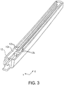
- FIG. 3 is a perspective view illustrating a structure of an arm shank of the wiper arm in FIG. 2 .
- FIG. 4 is a cross-sectional view cut along line A-A in FIG. 2 .
- the shape of a cross section cut in a Y-direction orthogonal to the longitudinal direction X of the arm shank 12 illustrated in FIG. 2 is substantially a U-shape as illustrated in FIG. 4 .
- the arm shank 12 includes a pair of inner wall surfaces 12a facing each other.
- the coupling engagement portion engaging with the adaptor (coupling member) 13 is formed on the inner wall surface 12a of the arm shank 12, and the adaptor 13 is mounted on an opening side (lower portion side in FIG. 4 ) having the U-shape as illustrated in FIG. 7 (which will be described below).
- the coupling engagement portion of Embodiment 1 is rail portions 12b formed to protrude inward from the inner wall surface 12a of the arm shank 12 illustrated in FIG. 3 , and these rail portions 12b are formed to be continuously connected in the longitudinal direction X of the wiper arm 22. That is, as illustrated in FIGS. 3 and 4 , a cross-sectional shape is a U-shape, and the rail portions 12b are continuously formed on each of the pair of inner wall surfaces 12a facing each other, in other words, the rail portion 12b is a guide portion for the adaptor 13 moving in the longitudinal direction X.
- the rail portions 12b are formed vertically in two stages when the U-shaped opening side is referred to as the lower side.
- FIG. 5 is a perspective view illustrating a coupling member of Embodiment 1 embedded in the coupling structure of the wiper arm in FIG. 1 .
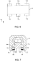
- FIG. 6 is a plan view of the coupling member in FIG. 5 .
- the adaptor 13 illustrated in FIG. 5 engages with the arm shank 12 illustrated in FIG. 2 and can slidably move in the longitudinal direction X inside the wiper arm 22. That is, on the right side and the left side toward the inner wall surfaces 12a of the arm shank 12 facing each other in FIG. 4 in the structure illustrated FIG. 5 , a protruding portion 13a engaging with the rail portion 12b on the lower stage side on each of the inner wall surfaces 12a on the right side and the left side of the arm shank 12 is provided on both side surfaces of the adaptor 13.
- the adaptor 13 includes extended portions (portions) 13b formed separately from the protruding portion 13a with a gap therebetween on both side surfaces thereof.
- the two extended portions 13b are provided at the same height on each of the side surfaces of the adaptor 13 of Embodiment 1.
- the right and left protruding portions 13a of the adaptor 13 are guided to the rail portions 12b on the lower stage side provided on the inner wall surfaces 12a of the arm shank 12 and the protruding portions 13a engage with the rail portions 12b, so that the adaptor 13 can slidably move on the rail portions 12b.
- a circular cut-out portion 13c is formed below the protruding portion 13a on both side surfaces of the adaptor 13.
- the cut-out portion 13c is provided below the protruding portion 13a on both side surfaces of the adaptor 13.
- the blade holding member 14 holding the wiper blade 10 illustrated in FIG. 1 is pivotably fitted into the cut-out portions 13c.
- the rail portion 12b of the arm shank 12 on the lower stage side is disposed between the protruding portion 13a and the extended portion 13b of the adaptor 13 as illustrated in FIG. 7 (which will be described below).
- FIG. 7 is a cross-sectional view illustrating a joint structure of the arm shank and the coupling member cut along line A-A in FIG. 2 .
- FIG. 8 is a perspective view illustrating the fixing method for the coupling member in the coupling structure of the wiper arm of Embodiment 1.
- FIG. 9 is a perspective view partially illustrating an engagement structure of the coupling member and a blade holding member in the coupling structure of the wiper arm of Embodiment 1.
- a fixture 17 is mounted in accordance with a position where the adaptor 13 is fixed inside the arm shank 12.
- the adaptor 13 is mounted from the opening part below the arm shank 12 (P1 part in FIG. 8 ), and the right and left extended portions 13b of the adaptor 13 are guided by the rail portions 12b on the lower stage side (upper stage side in FIG. 8 ) provided on the inner wall surfaces 12a of the arm shank 12.
- the extended portions 13b of the adaptor 13 are slidably moved on the rail portions 12b.
- the fixture 17 sets the position of the adaptor 13 in the longitudinal direction X of the arm shank 12 by causing the adaptor 13 to butt the fixture 17.
- the rail portions 12b of the arm shank 12 and the extended portions (portion) 13b of the adaptor 13 are fixed to each other through thermal caulking.
- the extended portions 13b of the adaptor 13 and the rail portions 12b of the arm shank 12 are welded through thermal caulking processing, and the adaptor 13 is fixed at a desired position in the longitudinal direction X of the arm shank 12. Accordingly, weld portions are formed in the N parts.
- the blade holding member 14 is attached to the adaptor 13 which has been attached to the arm shank 12.
- the wiper blade 10 having the blade rubber 20 is mounted in the blade holding member 14.
- projection portions 14a of the blade holding member 14 are fitted into the cut-out portions 13c of the adaptor 13. Accordingly, the blade holding member 14 engages with the adaptor 13.
- the projection portion 14a of the blade holding member 14 and the cut-out portion 13c of the adaptor 13 have a circular shape, the blade holding member 14 is attached pivotably with respect to the adaptor 13.
- the arm shank 12 is formed of polyethylene terephthalate (PET).
- the adaptor 13 is formed of polybutylene terephthalate (PBT).
- the blade holding member 14 is formed of polyacetal (POM).
- the materials for the foregoing members are not limited to the materials described above.
- the coupling structure of the wiper arm 22 of Embodiment 1 since the coupling structure includes the adaptor 13 to connect the arm shank 12 of the wiper arm 22 and the blade holding member 14, the adaptor 13 can be fixed at a plurality of places in the longitudinal direction X of the arm shank 12.
- the wiper arm 22 of one kind which can be attached to the wiper blades 10 of a plurality of types having different lengths. That is, it is possible to provide a coupling structure of the wiper arm 22 which is applicable to the wiper blades 10 of a plurality of types having different lengths.
- the blade holding member 14 can be fixed at an arbitrary place in the longitudinal direction X of the arm shank 12. That is, the wiper blade 10 can be fixed to the arm shank 12 at any position.
- the structure of the arm shank 12 can be a simple structure.
- the structure of the wiper arm 22 on the shank side can be a simple structure by providing the adaptor side with accuracy of a sliding part in the coupling structure of the wiper arm 22. That is, in order to enhance the oscillation accuracy of the arm shank 12, the processing accuracy of the adaptor 13 itself may be further enhanced. It becomes no longer necessary for the arm shank 12 to have enhanced processing accuracy more than necessary by enhancing the processing accuracy of the adaptor 13, so that the structure of the arm shank 12 can be an easy structure.
- the arm shank 12 when the arm shank 12 is processed through molding, since the arm shank 12 has an easy structure, the arm shank 12 can be easily formed through molding.
- the adaptor 13 can also be formed of a material having high sliding properties, so that the reliability of the unit of the wiper arm 22 including the adaptor 13 can be maintained for a long time.
- FIG. 10(a) is a perspective view of the wiper arm 22 having a long wiper blade 10a
- FIG. 10(b) is a plan view illustrating a wiping region 18a of the wiper blade 10a in FIG. 10(a)
- FIG. 11(a) is a perspective view of the wiper arm 22 having a short wiper blade 10b
- FIG. 11(b) is a plan view illustrating a wiping region 18b of the wiper blade 10b in FIG. 11(a) .
- the wiper blade 10a illustrated in FIGs. 10(a) and 10(b) has a longer length than the wiper blade 10b illustrated in FIG. 11 , regarding the areas of the wiping regions 18a and 18b in the rear glass 11, the area of the wiping region 18a wiped by the wiper blade 10a is larger than the area of the wiping region 18b wiped by the wiper blade 10b.
- the position of the wiper blade 10 can be freely changed in accordance with the layout of the components based on variations in length of the wiper blade 10. Accordingly, the wiper arm 22, the adaptor 13, and the blade holding member 14 can become standard components.
- the fixing position of the adaptor 13 is not misaligned and deterioration in workability for a user can be prevented when the wiper blade 10 is replaced or the like.
- a member such as a screw is not used for fixing the adaptor 13 to the arm shank 12, increase in the number of components can be curbed.
- a coupling structure of a wiper arm of Embodiment 2 will be described. Similar to Embodiment 1, for example, the coupling structure of the wiper arm of Embodiment 2 forms a rear wiper apparatus (not illustrated) wiping the wiping surface of the rear glass 11 (illustrated in FIG. 10 ) provided in a vehicle such as an automobile.
- the coupling structure of the wiper arm of Embodiment 2 uses the arm shank 12 illustrated in FIG. 12 and an adaptor (coupling member) 15 illustrated in FIG. 13 in the coupling structure of the wiper arm 22 illustrated in FIG. 1 . Since the operation method for the wiper arm 22 (refer to FIG. 1 ) is similar to the operation method for the wiper arm 22 of Embodiment 1, description thereof will be omitted.
- the adaptor 15 in the longitudinal direction X of the slender arm shank 12, the adaptor 15 can be fixed at a selective position in the longitudinal direction X thereof.
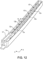
- FIG. 12 is a perspective view illustrating a structure of the arm shank in the wiper arm of Embodiment 2.
- the shape of a cross section cut in the Y-direction orthogonal to the longitudinal direction X of the arm shank 12 is substantially a U-shape.
- the arm shank 12 includes a plurality of coupling engagement portions which can fix the adaptor 15, and the plurality of coupling engagement portions are provided with an interval therebetween in the longitudinal direction X of the arm shank 12.
- the plurality of coupling engagement portions engaging with the adaptor (coupling member) 15 illustrated in FIG. 13 are formed on each of the pair of inner wall surfaces 12a of the arm shank 12 facing each other.
- the adaptor 15 is mounted from the U-shaped opening side, and the adaptor 15 is fixed to any of the plurality of coupling engagement portions.
- the coupling engagement portions of the wiper arm 22 of Embodiment 2 are a plurality of recess portions 12c formed on the (pair of) inner wall surfaces 12a on both sides of the arm shank 12 as illustrated in FIG. 12 .
- the plurality of recess portions 12c are formed in the longitudinal direction X of the arm shank 12. When viewed from the U-shaped opening side of the arm shank 12, unevenness is formed at equal intervals on each of the inner wall surfaces 12a on both sides. In other words, the plurality of recess portions 12c are formed at equal intervals on each of the inner wall surfaces 12a.
- the adaptor 15 can be fitted into the recess portion 12c at any position of the plurality of recess portions 12c.
- the interval T1 between the recess portions 12c adjacent to each other is 20 mm, for example.
- the recess portions 12c are provided at the same positions facing each other. Accordingly, the adaptor 15 can be mounted in any recess portion 12c as illustrated in FIG. 14 (which will be described below).
- FIG. 13 is a perspective view illustrating a coupling member embedded in the coupling structure of the wiper arm of Embodiment 2.
- the adaptor 15 illustrated in FIG. 13 engages with the arm shank 12 illustrated in FIG. 12 and is fixed at a selective position in the longitudinal direction X of the arm shank 12. That is, as illustrated in FIG. 14 (which will be described below), the position of the adaptor 15 can be determined and fixed with respect to the arm shank 12 by inserting the extended portions 15a of the adaptor 15 into any pair of the plurality of recess portions 12c of the arm shank 12 and mounting the adaptor 15.
- the extended portion (protruding portion) 15a is provided at four corners two each on both side surfaces thereof. Moreover, both ends of each extended portion 15a include a claw portion 15b protruding from the extended portion 15a along the side surface.
- a circular cut-out portion 15c is formed below central parts on both side surfaces thereof.
- the blade holding member 14 holding the wiper blade 10 illustrated in FIG. 1 is pivotably fitted into these cut-out portions 15c.
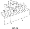
- FIG. 14 is a perspective view partially illustrating a mounting method for the coupling member in the coupling structure of the wiper arm of Embodiment 2.
- FIG. 15 is a perspective view partially illustrating details of a mounting structure of the coupling member of Embodiment 2.
- FIG. 16 is a perspective view partially illustrating an engagement structure of the coupling member and a blade holding member in the coupling structure of the wiper arm of Embodiment 2.
- the adaptor 15 When the adaptor 15 is mounted in the arm shank 12, as illustrated in FIG. 14 , in a state where the opening side of the arm shank 12 is directed upward, four extended portions 15a of the adaptor 15 are fitted into the recess portions 12c at predetermined places in the arm shank 12. At this time, as illustrated in FIG. 15 , the adaptor 15 is reliably pressed until the claw portions 15b of the adaptor 15 are hooked at wall portions 12ca forming the recess portions 12c. When the adaptor 15 is pressed into the recess portions 12c, the adaptor 15 may butt inner side surfaces of the arm shank 12. Accordingly, the claw portions 15b can be more reliably hooked at the wall portions 12ca.
- the extended portions 15a of the adaptor 15 are disposed (accommodated) in the recess portions 12c of the arm shank 12, and the claw portions 15b of the adaptor 15 engage with the wall portions 12ca forming the recess portions 12c, so that the position of the adaptor 15 is set and the adaptor 15 is in a state of being fixed to the arm shank 12. That is, position setting and attachment of the adaptor 15 with respect to the arm shank 12 are completed.
- the blade holding member 14 is attached to the adaptor 15 which has been attached to the arm shank 12.
- the wiper blade 10 having the blade rubber 20 is mounted in the blade holding member 14.
- the projection portions 14a of the blade holding member 14 are fitted into the cut-out portions 15c of the adaptor 15. Accordingly, the blade holding member 14 engages with the adaptor 15.
- the projection portion 14a of the blade holding member 14 and the cut-out portion 15c of the adaptor 15 have a circular shape, the blade holding member 14 is attached pivotably with respect to the adaptor 15.
- the coupling structure of the wiper arm 22 of Embodiment 2 since the coupling structure includes the adaptor 15 to connect the arm shank 12 of the wiper arm 22 and the blade holding member 14, the adaptor 15 can be fixed at a plurality of places in the longitudinal direction X of the arm shank 12. That is, since a plurality of fixing places for the adaptor 15 are provided in the arm shank 12, the adaptor 15 can be fixed at a selective position in the longitudinal direction X of the arm shank 12.
- the wiper arm 22 of one kind which can be attached to the wiper blades 10 of a plurality of types having different lengths. That is, it is possible to provide a coupling structure of the wiper arm 22 which is applicable to the wiper blades 10 of a plurality of types having different lengths.
- the structure of the arm shank 12 can be a simple structure.
- the structure of the wiper arm 22 on the shank side can be a simple structure by providing the adaptor side with accuracy of a sliding part in the coupling structure of the wiper arm 22. That is, in order to enhance the oscillation accuracy of the arm shank 12, the processing accuracy of the adaptor 15 itself may be further enhanced.
- the arm shank 12 it becomes no longer necessary for the arm shank 12 to have enhanced processing accuracy more than necessary by enhancing the processing accuracy of the adaptor 15, so that the structure of the arm shank 12 can be an easy structure.
- the arm shank 12 when the arm shank 12 is processed through molding, since the arm shank 12 has an easy structure, the arm shank 12 can be easily formed through molding.
- the adaptor 15 can also be formed of a material having high sliding properties, so that the reliability of the unit of the wiper arm 22 including the adaptor 15 can be maintained for a long time.
- the position of the wiper blade 10 can be selectively changed in accordance with the layout of the components based on variations in length of the wiper blade 10. Accordingly, the wiper arm 22, the adaptor 15, and the blade holding member 14 can become standard components.
- an optimal attachment position for the wiper blade 10 can be set in accordance with the type of automobile.
- the arm shank 12 and the adaptor 15 are fixed to each other through claw fixing by being fitted to each other, the fixing position of the adaptor 15 is not misaligned and deterioration in workability for a user can be prevented when the wiper blade 10 is replaced or the like.
- a member such as a screw is not used for fixing the adaptor 15 to the arm shank 12, increase in the number of components can be curbed.
- a coupling structure of a wiper arm of Embodiment 3 will be described. Similar to Embodiment 1, for example, the coupling structure of the wiper arm of Embodiment 3 forms a rear wiper apparatus (not illustrated) wiping the wiping surface of the rear glass 11 (illustrated in FIG. 10 ) provided in a vehicle such as an automobile.
- the coupling structure of the wiper arm of Embodiment 3 uses the arm shank 12 illustrated in FIG. 17 and an adaptor (coupling member) 16 illustrated in FIG. 18 in the coupling structure of the wiper arm 22 illustrated in FIG. 1 . Since the operation method for the wiper arm 22 (refer to FIG. 1 ) is similar to the operation method for the wiper arm 22 of Embodiment 1, description thereof will be omitted.
- the adaptor 16 can be fixed at a selective position in the longitudinal direction X of the arm shank 12.
- FIG. 17 is a perspective view illustrating a structure of the arm shank of the wiper arm of Embodiment 3.
- the shape of a cross section cut in the Y-direction orthogonal to the longitudinal direction X of the arm shank 12 illustrated in FIG. 17 is substantially a U-shape.
- the arm shank 12 includes a plurality of coupling engagement portions which can fix the adaptor 16, and the plurality of coupling engagement portions are provided with an interval therebetween in the longitudinal direction X of the arm shank 12.
- the plurality of coupling engagement portions engaging with the adaptor (coupling member) 16 illustrated in FIG. 18 are formed on each of the pair of inner wall surfaces 12a of the arm shank 12 of the wiper arm 22 facing each other.
- the adaptor 16 is mounted from the U-shaped opening side (P2 part in FIG. 19 ), and the adaptor 16 is fixed to any of the plurality of coupling engagement portions.
- the coupling engagement portions of the wiper arm 22 of Embodiment 3 are a plurality of circular recess portions 12d formed on (pair of) the inner wall surfaces 12a on both sides of the arm shank 12 as illustrated in FIG. 17 .
- the plurality of circular recess portions 12d are formed at equal intervals, for example, near the upper end (near the lower end in FIG. 17 ) of a slide rail 12e formed to protrude inward from the inner wall surface 12a in the longitudinal direction X of the arm shank 12. That is, the slide rail 12e formed to protrude from the inner wall surface 12a, and the plurality of recess portions 12d formed at equal intervals near the upper end of the slide rail 12e are formed such that they communicate with each other.
- the protruding portions 16a of the adaptor 16 illustrated in FIG. 18 are fitted into any pair of these plurality of recess portions 12d. Accordingly, the position of the adaptor 16 is set with respect to the arm shank 12 and is fixed to the arm shank 12. Therefore, in Embodiment 3 as well, the recess portions 12d of the arm shank 12 and the protruding portions 16a of the adaptor 16 are fitted to each other, and the adaptor 16 is fixed to the arm shank 12 due to this fitting.
- FIG. 18 is a perspective view illustrating a coupling member embedded in the coupling structure of the wiper arm of Embodiment 3.
- the adaptor 16 illustrated in FIG. 18 engages with the arm shank 12 illustrated in FIG. 17 and is fixed at a selective position in the longitudinal direction X of the arm shank 12.
- the adaptor 16 includes the protruding portion 16a protruding from each of the side surfaces.
- the protruding portion 16a has a columnar shape.
- the adaptor 16 is mounted from the opening part below the arm shank 12 (P2 part in FIG. 19 ), and the right and left protruding portions 16a are guided by the slide rails 12e provided on the inner wall surfaces 12a of the arm shank 12.
- the position of the adaptor 16 can be determined and fixed with respect to the arm shank 12 by causing the protruding portions 16a of the adaptor 16 to be fitted (press-fitted) into the recess portions 12d at desired positions.
- a circular cut-out portion 16b is formed below the protruding portions 16a on both side surfaces thereof.
- the blade holding member 14 holding the wiper blade 10 illustrated in FIG. 1 is pivotably fitted into these cut-out portion 16b.
- FIG. 19 is a perspective view illustrating a mounting method for the coupling member in the coupling structure of the wiper arm of Embodiment 3.
- FIG. 20 is a side view partially illustrating a press-fitting method for the coupling member of Embodiment 3.
- FIG. 21 is a perspective view partially illustrating a partially broken structure after the coupling member of Embodiment 3 is mounted.
- FIG. 22 is a perspective view partially illustrating an engagement structure of the coupling member and a blade holding member in the coupling structure of the wiper arm of Embodiment 3.
- the adaptor 16 When the adaptor 16 is mounted in the arm shank 12, as indicated with the P2 part in FIG. 19 , in a state where the opening side of the arm shank 12 is directed upward, the adaptor 16 is inserted into the arm shank 12. Thereafter, the adaptor 16 is moved along the slide rails 12e, and the protruding portions 16a are fitted into the recess portions 12d at desired positions as illustrated in FIG. 20 . That is, the protruding portions 16a of the adaptor 16 are lightly press-fitted into the recess portions 12d at desired positions in the arm shank 12. That is, the protruding portions 16a of the adaptor 16 and the recess portions 12d of the arm shank 12 engage with each other through press-fitting. Accordingly, the position of the adaptor 16 is set in the arm shank 12, and the adaptor 16 is in a state of being fixed to the arm shank 12.
- the distance between opening portions 12g facing each other in the recess portion 12d be smaller than the diameter of the protruding portion 16a to the extent that the protruding portion 16a of the adaptor 16 is not easily detached even when a load is applied in a detachment direction.
- a stopper portion 12f protruding inward from this ceiling part is provided in a ceiling part between the inner wall surfaces 12a of the arm shank 12.
- This stopper portion 12f prevents the adaptor 16 from falling off inside the arm shank 12 during wiping in which the wiper arm 22 operates. Therefore, a gap between the stopper portion 12f and the adaptor 16 is a small gap to the extent that the adaptor 16 does not fall off. That is, since the stopper portion 12f is provided in the ceiling part between the inner wall surfaces 12a of the arm shank 12, it is possible to prevent the adaptor 16 from falling off the recess portions 12d when a load in an S-direction is applied to the adaptor 16 during wiping.
- This stopper portion 12f may be a member which is detachably attached using an adhesive material or the like after the adaptor 16 is mounted and may be a member which is integrally formed with the arm shank 12. In addition, the stopper portion 12f may be provided to protrude from the side surfaces of the inner wall surfaces 12a of the arm shank 12.
- the blade holding member 14 is attached to the adaptor 16 which has been attached to the arm shank 12.
- the wiper blade 10 having the blade rubber 20 is mounted in the blade holding member 14.
- the projection portions 14a of the blade holding member 14 are fitted into the cut-out portions 16b of the adaptor 16. Accordingly, the blade holding member 14 engages with the adaptor 16.
- the blade holding member 14 is attached pivotably with respect to the adaptor 16.
- the coupling structure of the wiper arm 22 of Embodiment 3 since the coupling structure includes the adaptor 16 to connect the arm shank 12 of the wiper arm 22 and the blade holding member 14, the adaptor 16 can be fixed at a plurality of places in the longitudinal direction X of the arm shank 12. That is, since a plurality of fixing places for the adaptor 16 are provided in the arm shank 12, the adaptor 16 can be fixed at a selective position in the longitudinal direction X of the arm shank 12.
- the wiper arm 22 of one kind which can be attached to the wiper blades 10 of a plurality of types having different lengths. That is, it is possible to provide a coupling structure of the wiper arm 22 which is applicable to the wiper blades 10 of a plurality of types having different lengths.
- the structure of the arm shank 12 can be a simple structure.
- the structure of the wiper arm 22 on the shank side can be a simple structure by providing the adaptor side with accuracy of a sliding part in the coupling structure of the wiper arm 22. That is, in order to enhance the oscillation accuracy of the arm shank 12, the processing accuracy of the adaptor 16 itself may be further enhanced. It becomes no longer necessary for the arm shank 12 to have enhanced processing accuracy more than necessary by enhancing the processing accuracy of the adaptor 16, so that the structure of the arm shank 12 can be an easy structure.
- the arm shank 12 when the arm shank 12 is processed through molding, since the arm shank 12 has an easy structure, the arm shank 12 can be easily formed through molding.
- the adaptor 16 can also be formed of a material having high sliding properties, so that the reliability of the unit of the wiper arm 22 including the adaptor 16 can be maintained for a long time.
- the position of the wiper blade 10 can be selectively changed in accordance with the layout of the components based on variations in length of the wiper blade 10. Accordingly, the arm shank 12, the adaptor 16, and the blade holding member 14 can become standard components.
- an optimal attachment position for the wiper blade 10(adaptor 16) can be set in accordance with the type of automobile.
- the adaptor 16 is pivotably attached to coupling parts between the arm shank 12 and the protruding portions 16a of the adaptor 16.
- the blade holding member 14 is also pivotably attached for coupling between the cut-out portions 16b of the adaptor 16 and the projection portions 14a of the blade holding member 14 illustrated in FIG. 22 .
- the disclosure is not limited to the foregoing embodiments, and various changes can be made within a range not departing from the gist thereof.
- the foregoing embodiments have described an example in which the coupling structure of the wiper arm 22 is applied to a rear wiper apparatus wiping the rear glass 11 of a vehicle such as an automobile.
- the disclosure is not limited thereto and can also be applied to a wiper apparatus installed on a front side of a vehicle such as an automobile, or a wiper apparatus installed in a watercraft, an aircraft, a railroad car, and the like.
Landscapes
- Engineering & Computer Science (AREA)
- Mechanical Engineering (AREA)
- Cleaning Implements For Floors, Carpets, Furniture, Walls, And The Like (AREA)
- Ink Jet (AREA)
- Transmission Devices (AREA)
- Pivots And Pivotal Connections (AREA)
Abstract
Description
- The disclosure relates to a blade holding member holding a wiper blade and a coupling structure of a wiper arm.
- A wiper apparatus is installed in a vehicle such as an automobile. A wiper apparatus includes a wiper motor that serves as a driving source, a wiper arm that oscillates when the wiper motor is driven, and a wiper blade that is mounted on a distal end side of the wiper arm. The wiper blade is held by a blade holding member, and the blade holding member is coupled to the wiper arm. When the wiper motor is driven, the wiper blade performs reciprocating wiping operations on a wiping surface of a window glass of an automobile or the like.
- Patent Document 1 (Japanese Laid-Open Publication No.
2015-214181 - However, the coupling structure of the wiper arm and the wiper blade disclosed in the foregoing Patent Document 1 is a structure in which the wiper arm and the wiper blade are coupled to each other at one place when they are assembled.
- Therefore, when the length of the wiper blade is changed, the position of a coupling portion on a shank side also changes. Thus, there is a problem that when a coupling place is set at one place, there is a need to change the shape on the shank side in accordance with the length of the wiper blade.
- The disclosure provides a coupling structure of a wiper arm which is applicable to wiper blades of a plurality of types having different lengths.
- According to an embodiment of the disclosure, there is provided a coupling structure of a wiper arm coupled to a blade holding member in an attachable/detachable manner on the wiper arm. The coupling structure includes the wiper arm, a coupling member that is fixed to an arm shank constituting the wiper arm, and the blade holding member that engages with the coupling member and holds a wiper blade. The coupling member is positioned between the arm shank and the blade holding member. The arm shank includes a coupling engagement portion capable of fixing the coupling member at any position in a longitudinal direction of the arm shank.
- In the embodiment of the disclosure, the arm shank may include a pair of inner wall surfaces facing each other. The coupling engagement portion engaging with the coupling member may be formed on each of the inner wall surfaces. The coupling engagement portion may be continuously connected in the longitudinal direction of the arm shank.
- In the embodiment of the disclosure, the coupling structure may include a weld portion joining a portion of the coupling engagement portion and a portion of the coupling member to each other.
- In the embodiment of the disclosure, the coupling engagement portion may be a rail portion protruding from the inner wall surface of the arm shank. The coupling member may have a protruding portion engaging with the rail portion.
- In the embodiment of the disclosure, the coupling member may include an extended portion. The extended portion may be disposed separately from the protruding portion with a gap therebetween. The rail portion of the arm shank may be disposed between the protruding portion and the extended portion in the coupling member.
- According to the disclosure, since the coupling structure includes the coupling member to connect the arm shank of the wiper arm and the blade holding member, the blade holding member can be fixed at a plurality of places in the longitudinal direction of the arm shank via the coupling member. It is possible to realize a wiper arm of one kind which can be attached to wiper blades of a plurality of types having different lengths. That is, it is possible to provide a coupling structure of a wiper arm which is applicable to wiper blades of a plurality of types having different lengths.
-
-
FIG. 1 is a perspective view illustrating a coupling structure of a wiper arm of the disclosure. -
FIG. 2 is a perspective view illustrating the wiper arm used in the coupling structure of the wiper arm inFIG. 1 . -
FIG. 3 is a perspective view illustrating a structure of an arm shank of the wiper arm inFIG. 2 . -
FIG. 4 is a cross-sectional view cut along line A-A inFIG. 2 . -
FIG. 5 is a perspective view illustrating a coupling member of Embodiment 1 embedded in the coupling structure of the wiper arm inFIG. 1 . -
FIG. 6 is a plan view of the coupling member inFIG. 5 . -
FIG. 7 is a cross-sectional view illustrating a joint structure of the arm shank and the coupling member cut along line A-A inFIG. 2 . -
FIG. 8 is a perspective view illustrating a fixing method for the coupling member in the coupling structure of the wiper arm of Embodiment 1. -
FIG. 9 is a perspective view partially illustrating an engagement structure of the coupling member and a blade holding member in the coupling structure of the wiper arm of Embodiment 1. -
FIG. 10(a) is a perspective view of a wiper arm having a long wiper blade, andFIG. 10(b) is a plan view illustrating a wiping region of the wiper blade inFIG. 10(a) . -
FIG. 11(a) is a perspective view of a wiper arm having a short wiper blade, andFIG. 11(b) is a plan view illustrating a wiping region of the wiper blade inFIG. 11(a) . -
FIG. 12 is a perspective view illustrating a structure of an arm shank of a wiper arm of Embodiment 2. -
FIG. 13 is a perspective view illustrating a coupling member embedded in a coupling structure of the wiper arm of Embodiment 2. -
FIG. 14 is a perspective view partially illustrating a mounting method for the coupling member in the coupling structure of the wiper arm of Embodiment 2. -
FIG. 15 is a perspective view partially illustrating details of a mounting structure of the coupling member of Embodiment 2. -
FIG. 16 is a perspective view partially illustrating an engagement structure of the coupling member and a blade holding member in the coupling structure of the wiper arm of Embodiment 2. -
FIG. 17 is a perspective view illustrating a structure of an arm shank of a wiper arm of Embodiment 3. -
FIG. 18 is a perspective view illustrating a coupling member embedded in a coupling structure of the wiper arm of Embodiment 3. -
FIG. 19 is a perspective view illustrating a mounting method for the coupling member in the coupling structure of the wiper arm of Embodiment 3. -
FIG. 20 is a side view partially illustrating a press-fitting method for the coupling member of Embodiment 3. -
FIG. 21 is a perspective view partially illustrating a partially broken structure after the coupling member of Embodiment 3 is mounted. -
FIG. 22 is a perspective view partially illustrating an engagement structure of the coupling member and a blade holding member in the coupling structure of the wiper arm of Embodiment 3. - Hereinafter, embodiments of the disclosure will be described in detail using the drawings.
-
FIG. 1 is a perspective view illustrating a coupling structure of a wiper arm of the disclosure. - For example, the coupling structure of a
wiper arm 22 illustrated inFIG. 1 forms a rear wiper apparatus (not illustrated) wiping a wiping surface of a rear glass (refer toFIG. 10 ) 11 provided in a vehicle such as an automobile. The coupling structure of thewiper arm 22 has aslender arm shank 12 constituting thewiper arm 22, an adaptor (coupling member) 13, and ablade holding member 14 holding awiper blade 10. Thewiper arm 22 is constituted of thearm shank 12, and anarm head 21 pivotably supporting thearm shank 12. - In addition, the
wiper blade 10 is pivotably coupled to a place from a portion near a middle part in a longitudinal direction X of thearm shank 12 to a portion near a distal end part. An output shaft (not illustrated) of a wiper motor forming the rear wiper apparatus is fixed to a proximal end side of thewiper arm 22. - When a wiper switch provided inside a cabin or the like is turned on, the output shaft of the wiper motor rotates in normal and reverse directions, and the
wiper arm 22 oscillates. Accordingly, ablade rubber 20 performs reciprocating wiping operations within a predetermined wiping range on therear glass 11, thereby wiping off rain water or the like which has adhered to the wiping surface of therear glass 11. - The
wiper arm 22 is formed to have a rod shape through injection molding performed with a resin material such as a plastic, and the thickness of thewiper arm 22 on a distal end side is formed to be thinner than the thickness on the proximal end side. More specifically, thewiper arm 22 is formed to have a tapered shape which is gradually thinned from its proximal end side toward the distal end side. Accordingly, design of thewiper arm 22 is improved. - The
wiper arm 22 and theblade holding member 14 are coupled to each other via theadaptor 13 serving as a coupling member. That is, theadaptor 13 is fixed at a predetermined position in the longitudinal direction X of thearm shank 12 of thewiper arm 22 and is positioned between thearm shank 12 and theblade holding member 14. In addition, theblade holding member 14 engages with theadaptor 13 in a pivotable and attachable/detachable manner. - The
blade holding member 14 holds thewiper blade 10 in which theblade rubber 20 is provided, in a clasping manner. - In addition, a pressing force acts on the
arm shank 12 of thewiper arm 22 toward therear glass 11 in a direction in which thearm shank 12 is laid. Therefore, thewiper blade 10 does not fall off of thewiper arm 22 during reciprocating wiping operations of thewiper blade 10. The foregoing pressing force is generated due to a spring force of a pullingspring 19 provided on the proximal end side of thearm shank 12. - Here, the
arm shank 12 includes a coupling engagement portion capable of fixing theadaptor 13 at any position in the longitudinal direction X of thearm shank 12. Therefore, in the coupling structure of thewiper arm 22 of Embodiment 1, theadaptor 13 to be fixed at a predetermined position in the longitudinal direction X of thearm shank 12 of theslender wiper arm 22 can be fixed at an arbitrary position in the longitudinal direction X thereof. - A structure of the arm shank used in the coupling structure of the wiper arm of Embodiment 1 will be described using
FIGS. 2 to 4 .FIG. 2 is a perspective view illustrating the wiper arm used in the coupling structure of the wiper arm inFIG. 1 .FIG. 3 is a perspective view illustrating a structure of an arm shank of the wiper arm inFIG. 2 .FIG. 4 is a cross-sectional view cut along line A-A inFIG. 2 . - In the
arm shank 12 in thewiper arm 22, the shape of a cross section cut in a Y-direction orthogonal to the longitudinal direction X of thearm shank 12 illustrated inFIG. 2 is substantially a U-shape as illustrated inFIG. 4 . Thearm shank 12 includes a pair ofinner wall surfaces 12a facing each other. The coupling engagement portion engaging with the adaptor (coupling member) 13 is formed on theinner wall surface 12a of thearm shank 12, and theadaptor 13 is mounted on an opening side (lower portion side inFIG. 4 ) having the U-shape as illustrated inFIG. 7 (which will be described below). - The coupling engagement portion of Embodiment 1 is
rail portions 12b formed to protrude inward from theinner wall surface 12a of thearm shank 12 illustrated inFIG. 3 , and theserail portions 12b are formed to be continuously connected in the longitudinal direction X of thewiper arm 22. That is, as illustrated inFIGS. 3 and4 , a cross-sectional shape is a U-shape, and therail portions 12b are continuously formed on each of the pair ofinner wall surfaces 12a facing each other, in other words, therail portion 12b is a guide portion for theadaptor 13 moving in the longitudinal direction X. In addition, therail portions 12b are formed vertically in two stages when the U-shaped opening side is referred to as the lower side. - Next, using
FIGS. 5 and6 , a structure of the adaptor (coupling member) 13 attached to thearm shank 12 will be described.FIG. 5 is a perspective view illustrating a coupling member of Embodiment 1 embedded in the coupling structure of the wiper arm inFIG. 1 .FIG. 6 is a plan view of the coupling member inFIG. 5 . - The
adaptor 13 illustrated inFIG. 5 engages with thearm shank 12 illustrated inFIG. 2 and can slidably move in the longitudinal direction X inside thewiper arm 22. That is, on the right side and the left side toward the inner wall surfaces 12a of thearm shank 12 facing each other inFIG. 4 in the structure illustratedFIG. 5 , a protrudingportion 13a engaging with therail portion 12b on the lower stage side on each of the inner wall surfaces 12a on the right side and the left side of thearm shank 12 is provided on both side surfaces of theadaptor 13. - In addition, as illustrated in
FIGS. 5 and6 , theadaptor 13 includes extended portions (portions) 13b formed separately from the protrudingportion 13a with a gap therebetween on both side surfaces thereof. The twoextended portions 13b are provided at the same height on each of the side surfaces of theadaptor 13 of Embodiment 1. - When the
adaptor 13 is mounted in thearm shank 12, the right and left protrudingportions 13a of theadaptor 13 are guided to therail portions 12b on the lower stage side provided on the inner wall surfaces 12a of thearm shank 12 and the protrudingportions 13a engage with therail portions 12b, so that theadaptor 13 can slidably move on therail portions 12b. - In addition, a circular cut-out
portion 13c is formed below the protrudingportion 13a on both side surfaces of theadaptor 13. The cut-outportion 13c is provided below the protrudingportion 13a on both side surfaces of theadaptor 13. Theblade holding member 14 holding thewiper blade 10 illustrated inFIG. 1 is pivotably fitted into the cut-outportions 13c. - When the
adaptor 13 is mounted in thearm shank 12, therail portion 12b of thearm shank 12 on the lower stage side is disposed between the protrudingportion 13a and theextended portion 13b of theadaptor 13 as illustrated inFIG. 7 (which will be described below). - Next, a mounting method for the
adaptor 13 with respect to thewiper arm 22, a fixing method for theadaptor 13, and a structure after a wiper blade is attached will be described usingFIGS. 7 to 9 .FIG. 7 is a cross-sectional view illustrating a joint structure of the arm shank and the coupling member cut along line A-A inFIG. 2 .FIG. 8 is a perspective view illustrating the fixing method for the coupling member in the coupling structure of the wiper arm of Embodiment 1.FIG. 9 is a perspective view partially illustrating an engagement structure of the coupling member and a blade holding member in the coupling structure of the wiper arm of Embodiment 1. - When the
adaptor 13 is mounted in thearm shank 12 of thewiper arm 22, first, as illustrated inFIG. 8 , afixture 17 is mounted in accordance with a position where theadaptor 13 is fixed inside thearm shank 12. In this state, theadaptor 13 is mounted from the opening part below the arm shank 12 (P1 part inFIG. 8 ), and the right and leftextended portions 13b of theadaptor 13 are guided by therail portions 12b on the lower stage side (upper stage side inFIG. 8 ) provided on the inner wall surfaces 12a of thearm shank 12. At this time, theextended portions 13b of theadaptor 13 are slidably moved on therail portions 12b. Moreover, thefixture 17 sets the position of theadaptor 13 in the longitudinal direction X of thearm shank 12 by causing theadaptor 13 to butt thefixture 17. In this state, as indicated with N parts inFIG. 7 , therail portions 12b of thearm shank 12 and the extended portions (portion) 13b of theadaptor 13 are fixed to each other through thermal caulking. - That is, the
extended portions 13b of theadaptor 13 and therail portions 12b of thearm shank 12 are welded through thermal caulking processing, and theadaptor 13 is fixed at a desired position in the longitudinal direction X of thearm shank 12. Accordingly, weld portions are formed in the N parts. - After welding, the
fixture 17 is detached from thearm shank 12. - As illustrated in
FIG. 9 , theblade holding member 14 is attached to theadaptor 13 which has been attached to thearm shank 12. At this time, thewiper blade 10 having theblade rubber 20 is mounted in theblade holding member 14. When theblade holding member 14 is attached to theadaptor 13,projection portions 14a of theblade holding member 14 are fitted into the cut-outportions 13c of theadaptor 13. Accordingly, theblade holding member 14 engages with theadaptor 13. At this time, since theprojection portion 14a of theblade holding member 14 and the cut-outportion 13c of theadaptor 13 have a circular shape, theblade holding member 14 is attached pivotably with respect to theadaptor 13. - Here, materials for forming the
arm shank 12, theadaptor 13, and theblade holding member 14 will be described. As an example, thearm shank 12 is formed of polyethylene terephthalate (PET). As an example, theadaptor 13 is formed of polybutylene terephthalate (PBT). As an example, theblade holding member 14 is formed of polyacetal (POM). However, the materials for the foregoing members are not limited to the materials described above. - According to the coupling structure of the
wiper arm 22 of Embodiment 1, since the coupling structure includes theadaptor 13 to connect thearm shank 12 of thewiper arm 22 and theblade holding member 14, theadaptor 13 can be fixed at a plurality of places in the longitudinal direction X of thearm shank 12. - Accordingly, it is possible to realize the
wiper arm 22 of one kind which can be attached to thewiper blades 10 of a plurality of types having different lengths. That is, it is possible to provide a coupling structure of thewiper arm 22 which is applicable to thewiper blades 10 of a plurality of types having different lengths. - In addition, in the coupling member of the
wiper arm 22 of Embodiment 1, since theadaptor 13 can be fixed at an arbitrary position in the longitudinal direction X of thearm shank 12, theblade holding member 14 can be fixed at an arbitrary place in the longitudinal direction X of thearm shank 12. That is, thewiper blade 10 can be fixed to thearm shank 12 at any position. - In addition, in the coupling structure of the
wiper arm 22 of Embodiment 1, since the coupling structure includes theadaptor 13 to connect thearm shank 12 of thewiper arm 22 and theblade holding member 14, the structure of thearm shank 12 can be a simple structure. Specifically, the structure of thewiper arm 22 on the shank side can be a simple structure by providing the adaptor side with accuracy of a sliding part in the coupling structure of thewiper arm 22. That is, in order to enhance the oscillation accuracy of thearm shank 12, the processing accuracy of theadaptor 13 itself may be further enhanced. It becomes no longer necessary for thearm shank 12 to have enhanced processing accuracy more than necessary by enhancing the processing accuracy of theadaptor 13, so that the structure of thearm shank 12 can be an easy structure. In addition, when thearm shank 12 is processed through molding, since thearm shank 12 has an easy structure, thearm shank 12 can be easily formed through molding. Moreover, theadaptor 13 can also be formed of a material having high sliding properties, so that the reliability of the unit of thewiper arm 22 including theadaptor 13 can be maintained for a long time. - Here,
FIG. 10(a) is a perspective view of thewiper arm 22 having along wiper blade 10a, andFIG. 10(b) is a plan view illustrating awiping region 18a of thewiper blade 10a inFIG. 10(a) . In addition,FIG. 11(a) is a perspective view of thewiper arm 22 having ashort wiper blade 10b, andFIG. 11(b) is a plan view illustrating awiping region 18b of thewiper blade 10b inFIG. 11(a) . - Since the
wiper blade 10a illustrated inFIGs. 10(a) and 10(b) has a longer length than thewiper blade 10b illustrated inFIG. 11 , regarding the areas of thewiping regions rear glass 11, the area of the wipingregion 18a wiped by thewiper blade 10a is larger than the area of the wipingregion 18b wiped by thewiper blade 10b. - It is possible to realize the
wiper arm 22 of one kind which can be attached to thewiper blades 10 having different lengths by employing the coupling structure of thewiper arm 22 of Embodiment 1. - In addition, according to the coupling structure of the
wiper arm 22 of Embodiment 1, the position of thewiper blade 10 can be freely changed in accordance with the layout of the components based on variations in length of thewiper blade 10. Accordingly, thewiper arm 22, theadaptor 13, and theblade holding member 14 can become standard components. - In addition, since the rail portions (coupling engagement portion) 12b of the
arm shank 12 are continuously formed in the longitudinal direction X of thearm shank 12, an optimal attachment position for thewiper blade 10 can be set in accordance with the type of automobile. - In addition, since the
arm shank 12 and theadaptor 13 are fixed to each other through thermal caulking, the fixing position of theadaptor 13 is not misaligned and deterioration in workability for a user can be prevented when thewiper blade 10 is replaced or the like. Moreover, since a member such as a screw is not used for fixing theadaptor 13 to thearm shank 12, increase in the number of components can be curbed. - A coupling structure of a wiper arm of Embodiment 2 will be described. Similar to Embodiment 1, for example, the coupling structure of the wiper arm of Embodiment 2 forms a rear wiper apparatus (not illustrated) wiping the wiping surface of the rear glass 11 (illustrated in
FIG. 10 ) provided in a vehicle such as an automobile. - In addition, the coupling structure of the wiper arm of Embodiment 2 uses the
arm shank 12 illustrated inFIG. 12 and an adaptor (coupling member) 15 illustrated inFIG. 13 in the coupling structure of thewiper arm 22 illustrated inFIG. 1 . Since the operation method for the wiper arm 22 (refer toFIG. 1 ) is similar to the operation method for thewiper arm 22 of Embodiment 1, description thereof will be omitted. - In the coupling structure of the
wiper arm 22 of Embodiment 2, in the longitudinal direction X of theslender arm shank 12, theadaptor 15 can be fixed at a selective position in the longitudinal direction X thereof. - First, using
FIG. 12 , a structure of the wiper arm of Embodiment 2 will be described.FIG. 12 is a perspective view illustrating a structure of the arm shank in the wiper arm of Embodiment 2. - In the
wiper arm 22 of Embodiment 2, similar to the structure of Embodiment 1 inFIG. 4 , the shape of a cross section cut in the Y-direction orthogonal to the longitudinal direction X of thearm shank 12 is substantially a U-shape. Thearm shank 12 includes a plurality of coupling engagement portions which can fix theadaptor 15, and the plurality of coupling engagement portions are provided with an interval therebetween in the longitudinal direction X of thearm shank 12. The plurality of coupling engagement portions engaging with the adaptor (coupling member) 15 illustrated inFIG. 13 (which will be described below) are formed on each of the pair of inner wall surfaces 12a of thearm shank 12 facing each other. As illustrated inFIG. 14 (which will be described below), theadaptor 15 is mounted from the U-shaped opening side, and theadaptor 15 is fixed to any of the plurality of coupling engagement portions. - The coupling engagement portions of the
wiper arm 22 of Embodiment 2 are a plurality ofrecess portions 12c formed on the (pair of) inner wall surfaces 12a on both sides of thearm shank 12 as illustrated inFIG. 12 . The plurality ofrecess portions 12c are formed in the longitudinal direction X of thearm shank 12. When viewed from the U-shaped opening side of thearm shank 12, unevenness is formed at equal intervals on each of the inner wall surfaces 12a on both sides. In other words, the plurality ofrecess portions 12c are formed at equal intervals on each of theinner wall surfaces 12a. Extended portions (protruding portions) 15a of theadaptor 15 illustrated inFIG. 13 (which will be described below) are fitted into (accommodated in) theserecess portions 12c. Therefore, in Embodiment 2, therecess portions 12c of thearm shank 12 and theextended portions 15a which are the protruding portions of theadaptor 15 are fitted to each other, and theadaptor 15 is fixed to thearm shank 12 due to this fitting. - In addition, since the extended portions (protruding portions) 15a of the
adaptor 15 are fitted into the plurality ofrecess portions 12c, an interval T1 between theextended portions 15a of theadaptor 15 and a distance T2 between therecess portions 12c adjacent to each other in thearm shank 12 are equal to each other (T1=T2). It is preferable that all of the installation intervals between the plurality ofrecess portions 12c in thearm shank 12 be equal to T1. That is, all of the installation intervals between the plurality ofrecess portions 12c in the arm shank 12 (distances T2 between therecess portions 12c) are provided to be equal intervals. At this time, due to the relationship of T2=T1, theadaptor 15 can be fitted into therecess portion 12c at any position of the plurality ofrecess portions 12c. When the plurality ofrecess portions 12c are provided at equal intervals, the interval T1 between therecess portions 12c adjacent to each other is 20 mm, for example. In addition, as illustrated inFIG. 12 , on each of the inner wall surfaces 12a of thearm shank 12 facing each other, therecess portions 12c are provided at the same positions facing each other. Accordingly, theadaptor 15 can be mounted in anyrecess portion 12c as illustrated inFIG. 14 (which will be described below). - Next, a structure of the adaptor (coupling member) 15 of Embodiment 2 will be described using
FIG. 13. FIG. 13 is a perspective view illustrating a coupling member embedded in the coupling structure of the wiper arm of Embodiment 2. - The
adaptor 15 illustrated inFIG. 13 engages with thearm shank 12 illustrated inFIG. 12 and is fixed at a selective position in the longitudinal direction X of thearm shank 12. That is, as illustrated inFIG. 14 (which will be described below), the position of theadaptor 15 can be determined and fixed with respect to thearm shank 12 by inserting theextended portions 15a of theadaptor 15 into any pair of the plurality ofrecess portions 12c of thearm shank 12 and mounting theadaptor 15. - In the
adaptor 15, the extended portion (protruding portion) 15a is provided at four corners two each on both side surfaces thereof. Moreover, both ends of eachextended portion 15a include aclaw portion 15b protruding from theextended portion 15a along the side surface. - In addition, in the
adaptor 15, a circular cut-outportion 15c is formed below central parts on both side surfaces thereof. Theblade holding member 14 holding thewiper blade 10 illustrated inFIG. 1 is pivotably fitted into these cut-outportions 15c. - Next, a mounting method for the
adaptor 15 with respect to thearm shank 12, and a structure after a wiper blade is attached will be described usingFIGS. 14 to 16 .FIG. 14 is a perspective view partially illustrating a mounting method for the coupling member in the coupling structure of the wiper arm of Embodiment 2.FIG. 15 is a perspective view partially illustrating details of a mounting structure of the coupling member of Embodiment 2.FIG. 16 is a perspective view partially illustrating an engagement structure of the coupling member and a blade holding member in the coupling structure of the wiper arm of Embodiment 2. - When the
adaptor 15 is mounted in thearm shank 12, as illustrated inFIG. 14 , in a state where the opening side of thearm shank 12 is directed upward, fourextended portions 15a of theadaptor 15 are fitted into therecess portions 12c at predetermined places in thearm shank 12. At this time, as illustrated inFIG. 15 , theadaptor 15 is reliably pressed until theclaw portions 15b of theadaptor 15 are hooked at wall portions 12ca forming therecess portions 12c. When theadaptor 15 is pressed into therecess portions 12c, theadaptor 15 may butt inner side surfaces of thearm shank 12. Accordingly, theclaw portions 15b can be more reliably hooked at the wall portions 12ca. - Consequently, the
extended portions 15a of theadaptor 15 are disposed (accommodated) in therecess portions 12c of thearm shank 12, and theclaw portions 15b of theadaptor 15 engage with the wall portions 12ca forming therecess portions 12c, so that the position of theadaptor 15 is set and theadaptor 15 is in a state of being fixed to thearm shank 12. That is, position setting and attachment of theadaptor 15 with respect to thearm shank 12 are completed. - As illustrated in
FIG. 16 , theblade holding member 14 is attached to theadaptor 15 which has been attached to thearm shank 12. At this time, thewiper blade 10 having theblade rubber 20 is mounted in theblade holding member 14. When theblade holding member 14 is attached to theadaptor 15, theprojection portions 14a of theblade holding member 14 are fitted into the cut-outportions 15c of theadaptor 15. Accordingly, theblade holding member 14 engages with theadaptor 15. At this time, since theprojection portion 14a of theblade holding member 14 and the cut-outportion 15c of theadaptor 15 have a circular shape, theblade holding member 14 is attached pivotably with respect to theadaptor 15. - Since materials for forming the
arm shank 12, theadaptor 15, and theblade holding member 14 are similar to those described in Embodiment 1, duplicated description thereof will be omitted. - According to the coupling structure of the
wiper arm 22 of Embodiment 2, since the coupling structure includes theadaptor 15 to connect thearm shank 12 of thewiper arm 22 and theblade holding member 14, theadaptor 15 can be fixed at a plurality of places in the longitudinal direction X of thearm shank 12. That is, since a plurality of fixing places for theadaptor 15 are provided in thearm shank 12, theadaptor 15 can be fixed at a selective position in the longitudinal direction X of thearm shank 12. - Accordingly, it is possible to realize the
wiper arm 22 of one kind which can be attached to thewiper blades 10 of a plurality of types having different lengths. That is, it is possible to provide a coupling structure of thewiper arm 22 which is applicable to thewiper blades 10 of a plurality of types having different lengths. - In addition, in the coupling structure of the
wiper arm 22 of Embodiment 2, similar to Embodiment 1, since the coupling structure includes theadaptor 15 to connect thearm shank 12 of thewiper arm 22 and theblade holding member 14, the structure of thearm shank 12 can be a simple structure. Specifically, the structure of thewiper arm 22 on the shank side can be a simple structure by providing the adaptor side with accuracy of a sliding part in the coupling structure of thewiper arm 22. That is, in order to enhance the oscillation accuracy of thearm shank 12, the processing accuracy of theadaptor 15 itself may be further enhanced. It becomes no longer necessary for thearm shank 12 to have enhanced processing accuracy more than necessary by enhancing the processing accuracy of theadaptor 15, so that the structure of thearm shank 12 can be an easy structure. In addition, when thearm shank 12 is processed through molding, since thearm shank 12 has an easy structure, thearm shank 12 can be easily formed through molding. Moreover, theadaptor 15 can also be formed of a material having high sliding properties, so that the reliability of the unit of thewiper arm 22 including theadaptor 15 can be maintained for a long time. - In addition, according to the coupling structure of the
wiper arm 22 of Embodiment 2, the position of thewiper blade 10 can be selectively changed in accordance with the layout of the components based on variations in length of thewiper blade 10. Accordingly, thewiper arm 22, theadaptor 15, and theblade holding member 14 can become standard components. - In addition, since a plurality of fixing places for the
adaptor 15 are formed in the longitudinal direction X of thearm shank 12, an optimal attachment position for the wiper blade 10 (adaptor 15) can be set in accordance with the type of automobile. - In addition, due to unevenness engagement between the
arm shank 12 and theadaptor 15, attachment work of theadaptor 15 with respect to thearm shank 12 can be easily performed. - In addition, since the
arm shank 12 and theadaptor 15 are fixed to each other through claw fixing by being fitted to each other, the fixing position of theadaptor 15 is not misaligned and deterioration in workability for a user can be prevented when thewiper blade 10 is replaced or the like. Moreover, since a member such as a screw is not used for fixing theadaptor 15 to thearm shank 12, increase in the number of components can be curbed. - A coupling structure of a wiper arm of Embodiment 3 will be described. Similar to Embodiment 1, for example, the coupling structure of the wiper arm of Embodiment 3 forms a rear wiper apparatus (not illustrated) wiping the wiping surface of the rear glass 11 (illustrated in
FIG. 10 ) provided in a vehicle such as an automobile. - In addition, the coupling structure of the wiper arm of Embodiment 3 uses the
arm shank 12 illustrated inFIG. 17 and an adaptor (coupling member) 16 illustrated inFIG. 18 in the coupling structure of thewiper arm 22 illustrated inFIG. 1 . Since the operation method for the wiper arm 22 (refer toFIG. 1 ) is similar to the operation method for thewiper arm 22 of Embodiment 1, description thereof will be omitted. - In the coupling structure of the
wiper arm 22 of Embodiment 3, in the longitudinal direction X of theslender arm shank 12, similar to Embodiment 2, theadaptor 16 can be fixed at a selective position in the longitudinal direction X of thearm shank 12. - First, using
FIG. 17 , a structure of thewiper arm 22 of Embodiment 3 will be described.FIG. 17 is a perspective view illustrating a structure of the arm shank of the wiper arm of Embodiment 3. - In the
wiper arm 22 of Embodiment 3, similar to the structure of Embodiment 1 inFIG. 4 , the shape of a cross section cut in the Y-direction orthogonal to the longitudinal direction X of thearm shank 12 illustrated inFIG. 17 is substantially a U-shape. Thearm shank 12 includes a plurality of coupling engagement portions which can fix theadaptor 16, and the plurality of coupling engagement portions are provided with an interval therebetween in the longitudinal direction X of thearm shank 12. The plurality of coupling engagement portions engaging with the adaptor (coupling member) 16 illustrated inFIG. 18 (which will be described below) are formed on each of the pair of inner wall surfaces 12a of thearm shank 12 of thewiper arm 22 facing each other. As illustrated inFIG. 19 (which will be described below), theadaptor 16 is mounted from the U-shaped opening side (P2 part inFIG. 19 ), and theadaptor 16 is fixed to any of the plurality of coupling engagement portions. - The coupling engagement portions of the
wiper arm 22 of Embodiment 3 are a plurality ofcircular recess portions 12d formed on (pair of) the inner wall surfaces 12a on both sides of thearm shank 12 as illustrated inFIG. 17 . Specifically, the plurality ofcircular recess portions 12d are formed at equal intervals, for example, near the upper end (near the lower end inFIG. 17 ) of aslide rail 12e formed to protrude inward from theinner wall surface 12a in the longitudinal direction X of thearm shank 12. That is, theslide rail 12e formed to protrude from theinner wall surface 12a, and the plurality ofrecess portions 12d formed at equal intervals near the upper end of theslide rail 12e are formed such that they communicate with each other. - The protruding
portions 16a of theadaptor 16 illustrated inFIG. 18 (which will be described below) are fitted into any pair of these plurality ofrecess portions 12d. Accordingly, the position of theadaptor 16 is set with respect to thearm shank 12 and is fixed to thearm shank 12. Therefore, in Embodiment 3 as well, therecess portions 12d of thearm shank 12 and the protrudingportions 16a of theadaptor 16 are fitted to each other, and theadaptor 16 is fixed to thearm shank 12 due to this fitting. - Next, a structure of the adaptor (coupling member) 16 of Embodiment 3 will be described using
FIG. 18. FIG. 18 is a perspective view illustrating a coupling member embedded in the coupling structure of the wiper arm of Embodiment 3. - The
adaptor 16 illustrated inFIG. 18 engages with thearm shank 12 illustrated inFIG. 17 and is fixed at a selective position in the longitudinal direction X of thearm shank 12. On both side surfaces, theadaptor 16 includes the protrudingportion 16a protruding from each of the side surfaces. The protrudingportion 16a has a columnar shape. As illustrated inFIG. 19 (which will be described below), theadaptor 16 is mounted from the opening part below the arm shank 12 (P2 part inFIG. 19 ), and the right and left protrudingportions 16a are guided by theslide rails 12e provided on the inner wall surfaces 12a of thearm shank 12. Moreover, the position of theadaptor 16 can be determined and fixed with respect to thearm shank 12 by causing the protrudingportions 16a of theadaptor 16 to be fitted (press-fitted) into therecess portions 12d at desired positions. - In the
adaptor 16, a circular cut-outportion 16b is formed below the protrudingportions 16a on both side surfaces thereof. Theblade holding member 14 holding thewiper blade 10 illustrated inFIG. 1 is pivotably fitted into these cut-outportion 16b. - Next, a mounting method for the
adaptor 16 with respect to thearm shank 12, and a structure after a wiper blade is attached will be described usingFIGS. 19 to 22 .FIG. 19 is a perspective view illustrating a mounting method for the coupling member in the coupling structure of the wiper arm of Embodiment 3.FIG. 20 is a side view partially illustrating a press-fitting method for the coupling member of Embodiment 3. In addition,FIG. 21 is a perspective view partially illustrating a partially broken structure after the coupling member of Embodiment 3 is mounted.FIG. 22 is a perspective view partially illustrating an engagement structure of the coupling member and a blade holding member in the coupling structure of the wiper arm of Embodiment 3. - When the
adaptor 16 is mounted in thearm shank 12, as indicated with the P2 part inFIG. 19 , in a state where the opening side of thearm shank 12 is directed upward, theadaptor 16 is inserted into thearm shank 12. Thereafter, theadaptor 16 is moved along theslide rails 12e, and the protrudingportions 16a are fitted into therecess portions 12d at desired positions as illustrated inFIG. 20 . That is, the protrudingportions 16a of theadaptor 16 are lightly press-fitted into therecess portions 12d at desired positions in thearm shank 12. That is, the protrudingportions 16a of theadaptor 16 and therecess portions 12d of thearm shank 12 engage with each other through press-fitting. Accordingly, the position of theadaptor 16 is set in thearm shank 12, and theadaptor 16 is in a state of being fixed to thearm shank 12. - At this time, it is preferable that the distance between opening
portions 12g facing each other in therecess portion 12d be smaller than the diameter of the protrudingportion 16a to the extent that the protrudingportion 16a of theadaptor 16 is not easily detached even when a load is applied in a detachment direction. - As illustrated in
FIG. 21 , in a ceiling part between the inner wall surfaces 12a of thearm shank 12, astopper portion 12f protruding inward from this ceiling part is provided. Thisstopper portion 12f prevents theadaptor 16 from falling off inside thearm shank 12 during wiping in which thewiper arm 22 operates. Therefore, a gap between thestopper portion 12f and theadaptor 16 is a small gap to the extent that theadaptor 16 does not fall off. That is, since thestopper portion 12f is provided in the ceiling part between the inner wall surfaces 12a of thearm shank 12, it is possible to prevent theadaptor 16 from falling off therecess portions 12d when a load in an S-direction is applied to theadaptor 16 during wiping. Thisstopper portion 12f may be a member which is detachably attached using an adhesive material or the like after theadaptor 16 is mounted and may be a member which is integrally formed with thearm shank 12. In addition, thestopper portion 12f may be provided to protrude from the side surfaces of the inner wall surfaces 12a of thearm shank 12. - Next, as illustrated in
FIG. 22 , theblade holding member 14 is attached to theadaptor 16 which has been attached to thearm shank 12. At this time, thewiper blade 10 having theblade rubber 20 is mounted in theblade holding member 14. When theblade holding member 14 is attached to theadaptor 16, theprojection portions 14a of theblade holding member 14 are fitted into the cut-outportions 16b of theadaptor 16. Accordingly, theblade holding member 14 engages with theadaptor 16. At this time, since theprojection portion 14a of theblade holding member 14 and the cut-outportion 16b of theadaptor 16 have a circular shape, theblade holding member 14 is attached pivotably with respect to theadaptor 16. - Since materials for forming the
arm shank 12, theadaptor 16, and theblade holding member 14 are similar to those described in Embodiment 1, duplicated description thereof will be omitted. - According to the coupling structure of the
wiper arm 22 of Embodiment 3, since the coupling structure includes theadaptor 16 to connect thearm shank 12 of thewiper arm 22 and theblade holding member 14, theadaptor 16 can be fixed at a plurality of places in the longitudinal direction X of thearm shank 12. That is, since a plurality of fixing places for theadaptor 16 are provided in thearm shank 12, theadaptor 16 can be fixed at a selective position in the longitudinal direction X of thearm shank 12. - Accordingly, it is possible to realize the
wiper arm 22 of one kind which can be attached to thewiper blades 10 of a plurality of types having different lengths. That is, it is possible to provide a coupling structure of thewiper arm 22 which is applicable to thewiper blades 10 of a plurality of types having different lengths. - In addition, in the
wiper arm 22 of Embodiment 3, similar to Embodiment 1, since the coupling structure includes theadaptor 16 to connect thearm shank 12 of thewiper arm 22 and theblade holding member 14, the structure of thearm shank 12 can be a simple structure. Specifically, the structure of thewiper arm 22 on the shank side can be a simple structure by providing the adaptor side with accuracy of a sliding part in the coupling structure of thewiper arm 22. That is, in order to enhance the oscillation accuracy of thearm shank 12, the processing accuracy of theadaptor 16 itself may be further enhanced. It becomes no longer necessary for thearm shank 12 to have enhanced processing accuracy more than necessary by enhancing the processing accuracy of theadaptor 16, so that the structure of thearm shank 12 can be an easy structure. In addition, when thearm shank 12 is processed through molding, since thearm shank 12 has an easy structure, thearm shank 12 can be easily formed through molding. Moreover, theadaptor 16 can also be formed of a material having high sliding properties, so that the reliability of the unit of thewiper arm 22 including theadaptor 16 can be maintained for a long time. - In addition, according to the coupling structure of the
wiper arm 22 of Embodiment 3, the position of thewiper blade 10 can be selectively changed in accordance with the layout of the components based on variations in length of thewiper blade 10. Accordingly, thearm shank 12, theadaptor 16, and theblade holding member 14 can become standard components. - In addition, since a plurality of fixing places for the
adaptor 16 are formed in the longitudinal direction X of thearm shank 12, an optimal attachment position for the wiper blade 10(adaptor 16) can be set in accordance with the type of automobile. - In addition, due to engagement through light press-fitting between the
arm shank 12 of thewiper arm 22 and theadaptor 16, attachment work of theadaptor 16 with respect to thearm shank 12 can be easily performed. Moreover, the fixing position of theadaptor 16 is not misaligned and deterioration in workability for a user can be prevented when thewiper blade 10 is replaced or the like. In addition, since a member such as a screw is not used for fixing theadaptor 16 to thearm shank 12, increase in the number of components can be curbed. - In addition, in the coupling structure of the
wiper arm 22 of Embodiment 3, as indicated with a U part inFIG. 20 , theadaptor 16 is pivotably attached to coupling parts between thearm shank 12 and the protrudingportions 16a of theadaptor 16. Moreover, as indicated with a V part inFIG. 20 , theblade holding member 14 is also pivotably attached for coupling between the cut-outportions 16b of theadaptor 16 and theprojection portions 14a of theblade holding member 14 illustrated inFIG. 22 . - In this manner, in the
arm shank 12, since oscillation points are provided at two places close to each other, play of theblade holding member 14 increases, so that it is possible to enhance followability of thewiper blade 10 with respect to a curvature surface such as therear glass 11 illustrated inFIG. 10 , and it is possible to enhance wiping properties of thewiper arm 22. - It goes without saying that the disclosure is not limited to the foregoing embodiments, and various changes can be made within a range not departing from the gist thereof. The foregoing embodiments have described an example in which the coupling structure of the
wiper arm 22 is applied to a rear wiper apparatus wiping therear glass 11 of a vehicle such as an automobile. However, the disclosure is not limited thereto and can also be applied to a wiper apparatus installed on a front side of a vehicle such as an automobile, or a wiper apparatus installed in a watercraft, an aircraft, a railroad car, and the like. -
- 10, 10a, 10b Wiper blade
- 11 Rear glass
- 12 Arm shank
- 12a Inner wall surface
- 12b Rail portion (coupling engagement portion)
- 12c Recess portion (coupling engagement portion)
- 12d Recess portion (coupling engagement portion)
- 13 Adaptor (coupling member)
- 13a Protruding portion
- 13b Extended portion (portion)
- 13c Cut-out portion
- 14 Blade holding member
- 14a Projection portion
- 15 Adaptor (coupling member)
- 15a Extended portion (protruding portion)
- 15b Claw portion
- 15c Cut-out portion
- 16 Adaptor (coupling member)
- 16a Protruding portion
- 16b Cut-out portion
- 17 Fixture
- 20 Blade rubber
- 21 Arm head
- 22 Wiper arm
Claims (5)
- A coupling structure of a wiper arm (22) coupled to a blade holding member (14) in an attachable/detachable manner on the wiper arm (22), the coupling structure comprising:the wiper arm (22);a coupling member (13) that is fixed to an arm shank (12) constituting the wiper arm (22); andthe blade holding member (14) that engages with the coupling member (13) and holds a wiper blade (10),wherein the coupling member (13) is positioned between the arm shank (12) and the blade holding member (14), andwherein the arm shank (12) comprises a coupling engagement portion (12b) capable of fixing the coupling member (13) at any position in a longitudinal direction of the arm shank (12).
- The coupling structure of a wiper arm (22) according to claim 1,
wherein the arm shank (12) comprises a pair of inner wall surfaces (12a) facing each other,
wherein the coupling engagement portion (12b) engaging with the coupling member (13) is formed on each of the inner wall surfaces (12a), and
wherein the coupling engagement portion (12b) is continuously connected in the longitudinal direction of the arm shank (12). - The coupling structure of a wiper arm (22) according to claim 2, comprising a weld portion (N) joining a portion of the coupling engagement portion (12b) and a portion of the coupling member (13) to each other is formed.
- The coupling structure of a wiper arm (22) according to claim 2 or 3,
wherein the coupling engagement portion (12b) is a rail portion protruding from the inner wall surface (12a) of the arm shank (12), and
wherein the coupling member (13) has a protruding portion (13a) engaging with the rail portion. - The coupling structure of a wiper arm (22) according to claim 4,
wherein the coupling member (13) comprises an extended portion (13b),
wherein the extended portion (13b) is disposed separately from the protruding portion (13a) with a gap therebetween, and
wherein the rail portion of the arm shank (12) is disposed between the protruding portion (13a) and the extended portion (13b) in the coupling member (13).
Applications Claiming Priority (1)
| Application Number | Priority Date | Filing Date | Title |
|---|---|---|---|
| JP2018142244A JP7034857B2 (en) | 2018-07-30 | 2018-07-30 | Wiper arm connection structure |
Publications (2)
| Publication Number | Publication Date |
|---|---|
| EP3604053A1 true EP3604053A1 (en) | 2020-02-05 |
| EP3604053B1 EP3604053B1 (en) | 2021-04-28 |
Family
ID=67297063
Family Applications (1)
| Application Number | Title | Priority Date | Filing Date |
|---|---|---|---|
| EP19186318.2A Active EP3604053B1 (en) | 2018-07-30 | 2019-07-15 | Coupling structure of wiper arm |
Country Status (3)
| Country | Link |
|---|---|
| EP (1) | EP3604053B1 (en) |
| JP (1) | JP7034857B2 (en) |
| CN (1) | CN110775020B (en) |
Citations (4)
| Publication number | Priority date | Publication date | Assignee | Title |
|---|---|---|---|---|
| DE102012110859A1 (en) * | 2012-11-12 | 2014-05-15 | Valeo Wischersysteme Gmbh | Wiper arm for a wiper blade for cleaning a vehicle window and wiper device for cleaning a vehicle window |
| JP2015214181A (en) | 2014-05-08 | 2015-12-03 | 株式会社ミツバ | Connection structure for wiper blade |
| FR3022201A1 (en) * | 2014-06-11 | 2015-12-18 | Renault Sas | BRUSH ARM FOR A REAR WINDOW WIPER SYSTEM OF A MOTOR VEHICLE |
| EP3330137A1 (en) * | 2015-07-27 | 2018-06-06 | Nippon Wiper Blade Co., Ltd. | Wiper assembly and joint member for wiper assembly |
Family Cites Families (4)
| Publication number | Priority date | Publication date | Assignee | Title |
|---|---|---|---|---|
| DE102010052308A1 (en) * | 2010-11-16 | 2012-05-16 | Daimler Ag | Wiper arm assembly and method for connecting a wiper blade to a wiper arm |
| DE102012011660A1 (en) * | 2012-06-13 | 2013-12-19 | Daimler Ag | Wiper blade, wiper arm and connection arrangement for a windshield wiper system of a vehicle |
| DE102012024966A1 (en) * | 2012-12-20 | 2013-08-01 | Daimler Ag | Wiper arm for windshield wiper system of vehicle, has attachment elements that are provided in connection portions for attaching wiper strip of wiper blade so that wiper strip is pivoted around pivot axis relative to wiper arm |
| JP6177979B2 (en) * | 2016-09-21 | 2017-08-09 | アスモ株式会社 | Wiper blade and wiper |
-
2018
- 2018-07-30 JP JP2018142244A patent/JP7034857B2/en active Active
-
2019
- 2019-07-15 EP EP19186318.2A patent/EP3604053B1/en active Active
- 2019-07-22 CN CN201910660900.1A patent/CN110775020B/en active Active
Patent Citations (4)
| Publication number | Priority date | Publication date | Assignee | Title |
|---|---|---|---|---|
| DE102012110859A1 (en) * | 2012-11-12 | 2014-05-15 | Valeo Wischersysteme Gmbh | Wiper arm for a wiper blade for cleaning a vehicle window and wiper device for cleaning a vehicle window |
| JP2015214181A (en) | 2014-05-08 | 2015-12-03 | 株式会社ミツバ | Connection structure for wiper blade |
| FR3022201A1 (en) * | 2014-06-11 | 2015-12-18 | Renault Sas | BRUSH ARM FOR A REAR WINDOW WIPER SYSTEM OF A MOTOR VEHICLE |
| EP3330137A1 (en) * | 2015-07-27 | 2018-06-06 | Nippon Wiper Blade Co., Ltd. | Wiper assembly and joint member for wiper assembly |
Also Published As
| Publication number | Publication date |
|---|---|
| CN110775020A (en) | 2020-02-11 |
| JP7034857B2 (en) | 2022-03-14 |
| EP3604053B1 (en) | 2021-04-28 |
| CN110775020B (en) | 2022-12-27 |
| JP2020019293A (en) | 2020-02-06 |
Similar Documents
| Publication | Publication Date | Title |
|---|---|---|
| CZ20013785A3 (en) | Windscreen wiper blade, particularly of vehicles | |
| JP4260745B2 (en) | Device for fixing windshield wiper blade to wiper arm | |
| US8429786B2 (en) | Connection device for the articulated connection of a wiper blade to a wiper arm | |
| CN104080665B (en) | For cleaning the Wiper system of vehicle window | |
| US20110247166A1 (en) | Connecting device for the articulated connection of a wiper blade to a wiper arm | |
| US20070011840A1 (en) | Windscreen wiper arm | |
| JP2014509985A (en) | Windshield wiper device | |
| JP2002536244A (en) | Wiper arm | |
| US20170136999A1 (en) | A windscreen wiper device | |
| CN105431336A (en) | Wiper arm for a windscreen wiper system of a motor vehicle, wiper frame and wiping device | |
| US20130340195A1 (en) | Wiper blade adapter device, in particular for a motor vehicle windscreen wiper device | |
| KR20170056456A (en) | Element for a system for connecting a windscreen wiper blade holder to a drive arm | |
| JP2009501664A (en) | Windshield wiper device | |
| EP3604053B1 (en) | Coupling structure of wiper arm | |
| KR101766944B1 (en) | Windscreen wiper device | |
| US9440620B2 (en) | Wiping device | |
| US11077831B2 (en) | Windscreen wiper device | |
| KR20160084388A (en) | Windscreen wiper device | |
| EP2790970B1 (en) | Windscreen wiper arm | |
| US20170197592A1 (en) | Windscreen wiper device | |
| KR100799087B1 (en) | Articulated element for a windscreen wiper | |
| KR101305350B1 (en) | A Wiper Blade Assembly | |
| JP2020019294A (en) | Connection structure of wiper arm | |
| US20200254977A1 (en) | A windscreen wiper device | |
| CN210680659U (en) | Windscreen wiper |
Legal Events
| Date | Code | Title | Description |
|---|---|---|---|
| PUAI | Public reference made under article 153(3) epc to a published international application that has entered the european phase |
Free format text: ORIGINAL CODE: 0009012 |
|
| STAA | Information on the status of an ep patent application or granted ep patent |
Free format text: STATUS: REQUEST FOR EXAMINATION WAS MADE |
|
| 17P | Request for examination filed |
Effective date: 20190715 |
|
| AK | Designated contracting states |
Kind code of ref document: A1 Designated state(s): AL AT BE BG CH CY CZ DE DK EE ES FI FR GB GR HR HU IE IS IT LI LT LU LV MC MK MT NL NO PL PT RO RS SE SI SK SM TR |
|
| AX | Request for extension of the european patent |
Extension state: BA ME |
|
| RBV | Designated contracting states (corrected) |
Designated state(s): AL AT BE BG CH CY CZ DE DK EE ES FI FR GB GR HR HU IE IS IT LI LT LU LV MC MK MT NL NO PL PT RO RS SE SI SK SM TR |
|
| GRAP | Despatch of communication of intention to grant a patent |
Free format text: ORIGINAL CODE: EPIDOSNIGR1 |
|
| STAA | Information on the status of an ep patent application or granted ep patent |
Free format text: STATUS: GRANT OF PATENT IS INTENDED |
|
| INTG | Intention to grant announced |
Effective date: 20210112 |
|
| GRAS | Grant fee paid |
Free format text: ORIGINAL CODE: EPIDOSNIGR3 |
|
| GRAA | (expected) grant |
Free format text: ORIGINAL CODE: 0009210 |
|
| STAA | Information on the status of an ep patent application or granted ep patent |
Free format text: STATUS: THE PATENT HAS BEEN GRANTED |
|
| AK | Designated contracting states |
Kind code of ref document: B1 Designated state(s): AL AT BE BG CH CY CZ DE DK EE ES FI FR GB GR HR HU IE IS IT LI LT LU LV MC MK MT NL NO PL PT RO RS SE SI SK SM TR |
|
| REG | Reference to a national code |
Ref country code: GB Ref legal event code: FG4D |
|
| REG | Reference to a national code |
Ref country code: CH Ref legal event code: EP |
|
| REG | Reference to a national code |
Ref country code: AT Ref legal event code: REF Ref document number: 1386736 Country of ref document: AT Kind code of ref document: T Effective date: 20210515 |
|
| REG | Reference to a national code |
Ref country code: DE Ref legal event code: R096 Ref document number: 602019004207 Country of ref document: DE |
|
| REG | Reference to a national code |
Ref country code: IE Ref legal event code: FG4D |
|
| REG | Reference to a national code |
Ref country code: LT Ref legal event code: MG9D |
|
| REG | Reference to a national code |
Ref country code: AT Ref legal event code: MK05 Ref document number: 1386736 Country of ref document: AT Kind code of ref document: T Effective date: 20210428 |
|
| PG25 | Lapsed in a contracting state [announced via postgrant information from national office to epo] |
Ref country code: HR Free format text: LAPSE BECAUSE OF FAILURE TO SUBMIT A TRANSLATION OF THE DESCRIPTION OR TO PAY THE FEE WITHIN THE PRESCRIBED TIME-LIMIT Effective date: 20210428 Ref country code: LT Free format text: LAPSE BECAUSE OF FAILURE TO SUBMIT A TRANSLATION OF THE DESCRIPTION OR TO PAY THE FEE WITHIN THE PRESCRIBED TIME-LIMIT Effective date: 20210428 Ref country code: FI Free format text: LAPSE BECAUSE OF FAILURE TO SUBMIT A TRANSLATION OF THE DESCRIPTION OR TO PAY THE FEE WITHIN THE PRESCRIBED TIME-LIMIT Effective date: 20210428 Ref country code: NL Free format text: LAPSE BECAUSE OF FAILURE TO SUBMIT A TRANSLATION OF THE DESCRIPTION OR TO PAY THE FEE WITHIN THE PRESCRIBED TIME-LIMIT Effective date: 20210428 Ref country code: AT Free format text: LAPSE BECAUSE OF FAILURE TO SUBMIT A TRANSLATION OF THE DESCRIPTION OR TO PAY THE FEE WITHIN THE PRESCRIBED TIME-LIMIT Effective date: 20210428 Ref country code: BG Free format text: LAPSE BECAUSE OF FAILURE TO SUBMIT A TRANSLATION OF THE DESCRIPTION OR TO PAY THE FEE WITHIN THE PRESCRIBED TIME-LIMIT Effective date: 20210728 |
|
| PG25 | Lapsed in a contracting state [announced via postgrant information from national office to epo] |
Ref country code: NO Free format text: LAPSE BECAUSE OF FAILURE TO SUBMIT A TRANSLATION OF THE DESCRIPTION OR TO PAY THE FEE WITHIN THE PRESCRIBED TIME-LIMIT Effective date: 20210728 Ref country code: PL Free format text: LAPSE BECAUSE OF FAILURE TO SUBMIT A TRANSLATION OF THE DESCRIPTION OR TO PAY THE FEE WITHIN THE PRESCRIBED TIME-LIMIT Effective date: 20210428 Ref country code: LV Free format text: LAPSE BECAUSE OF FAILURE TO SUBMIT A TRANSLATION OF THE DESCRIPTION OR TO PAY THE FEE WITHIN THE PRESCRIBED TIME-LIMIT Effective date: 20210428 Ref country code: RS Free format text: LAPSE BECAUSE OF FAILURE TO SUBMIT A TRANSLATION OF THE DESCRIPTION OR TO PAY THE FEE WITHIN THE PRESCRIBED TIME-LIMIT Effective date: 20210428 Ref country code: PT Free format text: LAPSE BECAUSE OF FAILURE TO SUBMIT A TRANSLATION OF THE DESCRIPTION OR TO PAY THE FEE WITHIN THE PRESCRIBED TIME-LIMIT Effective date: 20210830 Ref country code: SE Free format text: LAPSE BECAUSE OF FAILURE TO SUBMIT A TRANSLATION OF THE DESCRIPTION OR TO PAY THE FEE WITHIN THE PRESCRIBED TIME-LIMIT Effective date: 20210428 Ref country code: GR Free format text: LAPSE BECAUSE OF FAILURE TO SUBMIT A TRANSLATION OF THE DESCRIPTION OR TO PAY THE FEE WITHIN THE PRESCRIBED TIME-LIMIT Effective date: 20210729 Ref country code: IS Free format text: LAPSE BECAUSE OF FAILURE TO SUBMIT A TRANSLATION OF THE DESCRIPTION OR TO PAY THE FEE WITHIN THE PRESCRIBED TIME-LIMIT Effective date: 20210828 |
|
| REG | Reference to a national code |
Ref country code: NL Ref legal event code: MP Effective date: 20210428 |
|
| PG25 | Lapsed in a contracting state [announced via postgrant information from national office to epo] |
Ref country code: EE Free format text: LAPSE BECAUSE OF FAILURE TO SUBMIT A TRANSLATION OF THE DESCRIPTION OR TO PAY THE FEE WITHIN THE PRESCRIBED TIME-LIMIT Effective date: 20210428 Ref country code: ES Free format text: LAPSE BECAUSE OF FAILURE TO SUBMIT A TRANSLATION OF THE DESCRIPTION OR TO PAY THE FEE WITHIN THE PRESCRIBED TIME-LIMIT Effective date: 20210428 Ref country code: SK Free format text: LAPSE BECAUSE OF FAILURE TO SUBMIT A TRANSLATION OF THE DESCRIPTION OR TO PAY THE FEE WITHIN THE PRESCRIBED TIME-LIMIT Effective date: 20210428 Ref country code: SM Free format text: LAPSE BECAUSE OF FAILURE TO SUBMIT A TRANSLATION OF THE DESCRIPTION OR TO PAY THE FEE WITHIN THE PRESCRIBED TIME-LIMIT Effective date: 20210428 Ref country code: RO Free format text: LAPSE BECAUSE OF FAILURE TO SUBMIT A TRANSLATION OF THE DESCRIPTION OR TO PAY THE FEE WITHIN THE PRESCRIBED TIME-LIMIT Effective date: 20210428 Ref country code: DK Free format text: LAPSE BECAUSE OF FAILURE TO SUBMIT A TRANSLATION OF THE DESCRIPTION OR TO PAY THE FEE WITHIN THE PRESCRIBED TIME-LIMIT Effective date: 20210428 Ref country code: CZ Free format text: LAPSE BECAUSE OF FAILURE TO SUBMIT A TRANSLATION OF THE DESCRIPTION OR TO PAY THE FEE WITHIN THE PRESCRIBED TIME-LIMIT Effective date: 20210428 |
|
| REG | Reference to a national code |
Ref country code: DE Ref legal event code: R097 Ref document number: 602019004207 Country of ref document: DE |
|
| PLBE | No opposition filed within time limit |
Free format text: ORIGINAL CODE: 0009261 |
|
| STAA | Information on the status of an ep patent application or granted ep patent |
Free format text: STATUS: NO OPPOSITION FILED WITHIN TIME LIMIT |
|
| PG25 | Lapsed in a contracting state [announced via postgrant information from national office to epo] |
Ref country code: MC Free format text: LAPSE BECAUSE OF FAILURE TO SUBMIT A TRANSLATION OF THE DESCRIPTION OR TO PAY THE FEE WITHIN THE PRESCRIBED TIME-LIMIT Effective date: 20210428 |
|
| REG | Reference to a national code |
Ref country code: BE Ref legal event code: MM Effective date: 20210731 |
|
| 26N | No opposition filed |
Effective date: 20220131 |
|
| PG25 | Lapsed in a contracting state [announced via postgrant information from national office to epo] |
Ref country code: IS Free format text: LAPSE BECAUSE OF FAILURE TO SUBMIT A TRANSLATION OF THE DESCRIPTION OR TO PAY THE FEE WITHIN THE PRESCRIBED TIME-LIMIT Effective date: 20210828 Ref country code: LU Free format text: LAPSE BECAUSE OF NON-PAYMENT OF DUE FEES Effective date: 20210715 Ref country code: AL Free format text: LAPSE BECAUSE OF FAILURE TO SUBMIT A TRANSLATION OF THE DESCRIPTION OR TO PAY THE FEE WITHIN THE PRESCRIBED TIME-LIMIT Effective date: 20210428 |
|
| PG25 | Lapsed in a contracting state [announced via postgrant information from national office to epo] |
Ref country code: IT Free format text: LAPSE BECAUSE OF FAILURE TO SUBMIT A TRANSLATION OF THE DESCRIPTION OR TO PAY THE FEE WITHIN THE PRESCRIBED TIME-LIMIT Effective date: 20210428 Ref country code: IE Free format text: LAPSE BECAUSE OF NON-PAYMENT OF DUE FEES Effective date: 20210715 Ref country code: BE Free format text: LAPSE BECAUSE OF NON-PAYMENT OF DUE FEES Effective date: 20210731 |
|
| REG | Reference to a national code |
Ref country code: CH Ref legal event code: PL |
|
| PG25 | Lapsed in a contracting state [announced via postgrant information from national office to epo] |
Ref country code: LI Free format text: LAPSE BECAUSE OF NON-PAYMENT OF DUE FEES Effective date: 20220731 Ref country code: CH Free format text: LAPSE BECAUSE OF NON-PAYMENT OF DUE FEES Effective date: 20220731 |
|
| PG25 | Lapsed in a contracting state [announced via postgrant information from national office to epo] |
Ref country code: CY Free format text: LAPSE BECAUSE OF FAILURE TO SUBMIT A TRANSLATION OF THE DESCRIPTION OR TO PAY THE FEE WITHIN THE PRESCRIBED TIME-LIMIT Effective date: 20210428 |
|
| PG25 | Lapsed in a contracting state [announced via postgrant information from national office to epo] |
Ref country code: HU Free format text: LAPSE BECAUSE OF FAILURE TO SUBMIT A TRANSLATION OF THE DESCRIPTION OR TO PAY THE FEE WITHIN THE PRESCRIBED TIME-LIMIT; INVALID AB INITIO Effective date: 20190715 |
|
| GBPC | Gb: european patent ceased through non-payment of renewal fee |
Effective date: 20230715 |
|
| PG25 | Lapsed in a contracting state [announced via postgrant information from national office to epo] |
Ref country code: MK Free format text: LAPSE BECAUSE OF FAILURE TO SUBMIT A TRANSLATION OF THE DESCRIPTION OR TO PAY THE FEE WITHIN THE PRESCRIBED TIME-LIMIT Effective date: 20210428 Ref country code: GB Free format text: LAPSE BECAUSE OF NON-PAYMENT OF DUE FEES Effective date: 20230715 |
|
| PG25 | Lapsed in a contracting state [announced via postgrant information from national office to epo] |
Ref country code: TR Free format text: LAPSE BECAUSE OF FAILURE TO SUBMIT A TRANSLATION OF THE DESCRIPTION OR TO PAY THE FEE WITHIN THE PRESCRIBED TIME-LIMIT Effective date: 20210428 |
|
| PG25 | Lapsed in a contracting state [announced via postgrant information from national office to epo] |
Ref country code: MT Free format text: LAPSE BECAUSE OF FAILURE TO SUBMIT A TRANSLATION OF THE DESCRIPTION OR TO PAY THE FEE WITHIN THE PRESCRIBED TIME-LIMIT Effective date: 20210428 |
|
| PGFP | Annual fee paid to national office [announced via postgrant information from national office to epo] |
Ref country code: FR Payment date: 20250610 Year of fee payment: 7 |
|
| PGFP | Annual fee paid to national office [announced via postgrant information from national office to epo] |
Ref country code: DE Payment date: 20250528 Year of fee payment: 7 |