EP3604045A1 - Vehicular structure - Google Patents
Vehicular structure Download PDFInfo
- Publication number
- EP3604045A1 EP3604045A1 EP18770206.3A EP18770206A EP3604045A1 EP 3604045 A1 EP3604045 A1 EP 3604045A1 EP 18770206 A EP18770206 A EP 18770206A EP 3604045 A1 EP3604045 A1 EP 3604045A1
- Authority
- EP
- European Patent Office
- Prior art keywords
- bumper
- wall
- portions
- protrusion
- protrusions
- Prior art date
- Legal status (The legal status is an assumption and is not a legal conclusion. Google has not performed a legal analysis and makes no representation as to the accuracy of the status listed.)
- Granted
Links
Images






Classifications
-
- B—PERFORMING OPERATIONS; TRANSPORTING
- B60—VEHICLES IN GENERAL
- B60R—VEHICLES, VEHICLE FITTINGS, OR VEHICLE PARTS, NOT OTHERWISE PROVIDED FOR
- B60R19/00—Wheel guards; Radiator guards, e.g. grilles; Obstruction removers; Fittings damping bouncing force in collisions
- B60R19/02—Bumpers, i.e. impact receiving or absorbing members for protecting vehicles or fending off blows from other vehicles or objects
- B60R19/24—Arrangements for mounting bumpers on vehicles
- B60R19/26—Arrangements for mounting bumpers on vehicles comprising yieldable mounting means
- B60R19/34—Arrangements for mounting bumpers on vehicles comprising yieldable mounting means destroyed upon impact, e.g. one-shot type
-
- B—PERFORMING OPERATIONS; TRANSPORTING
- B60—VEHICLES IN GENERAL
- B60R—VEHICLES, VEHICLE FITTINGS, OR VEHICLE PARTS, NOT OTHERWISE PROVIDED FOR
- B60R19/00—Wheel guards; Radiator guards, e.g. grilles; Obstruction removers; Fittings damping bouncing force in collisions
- B60R19/02—Bumpers, i.e. impact receiving or absorbing members for protecting vehicles or fending off blows from other vehicles or objects
- B60R19/18—Bumpers, i.e. impact receiving or absorbing members for protecting vehicles or fending off blows from other vehicles or objects characterised by the cross-section; Means within the bumper to absorb impact
-
- B—PERFORMING OPERATIONS; TRANSPORTING
- B60—VEHICLES IN GENERAL
- B60R—VEHICLES, VEHICLE FITTINGS, OR VEHICLE PARTS, NOT OTHERWISE PROVIDED FOR
- B60R19/00—Wheel guards; Radiator guards, e.g. grilles; Obstruction removers; Fittings damping bouncing force in collisions
- B60R19/02—Bumpers, i.e. impact receiving or absorbing members for protecting vehicles or fending off blows from other vehicles or objects
- B60R19/023—Details
-
- B—PERFORMING OPERATIONS; TRANSPORTING
- B60—VEHICLES IN GENERAL
- B60R—VEHICLES, VEHICLE FITTINGS, OR VEHICLE PARTS, NOT OTHERWISE PROVIDED FOR
- B60R19/00—Wheel guards; Radiator guards, e.g. grilles; Obstruction removers; Fittings damping bouncing force in collisions
- B60R19/02—Bumpers, i.e. impact receiving or absorbing members for protecting vehicles or fending off blows from other vehicles or objects
- B60R19/24—Arrangements for mounting bumpers on vehicles
-
- B—PERFORMING OPERATIONS; TRANSPORTING
- B60—VEHICLES IN GENERAL
- B60R—VEHICLES, VEHICLE FITTINGS, OR VEHICLE PARTS, NOT OTHERWISE PROVIDED FOR
- B60R19/00—Wheel guards; Radiator guards, e.g. grilles; Obstruction removers; Fittings damping bouncing force in collisions
- B60R19/02—Bumpers, i.e. impact receiving or absorbing members for protecting vehicles or fending off blows from other vehicles or objects
- B60R19/24—Arrangements for mounting bumpers on vehicles
- B60R19/26—Arrangements for mounting bumpers on vehicles comprising yieldable mounting means
-
- B—PERFORMING OPERATIONS; TRANSPORTING
- B60—VEHICLES IN GENERAL
- B60R—VEHICLES, VEHICLE FITTINGS, OR VEHICLE PARTS, NOT OTHERWISE PROVIDED FOR
- B60R19/00—Wheel guards; Radiator guards, e.g. grilles; Obstruction removers; Fittings damping bouncing force in collisions
- B60R19/02—Bumpers, i.e. impact receiving or absorbing members for protecting vehicles or fending off blows from other vehicles or objects
- B60R19/18—Bumpers, i.e. impact receiving or absorbing members for protecting vehicles or fending off blows from other vehicles or objects characterised by the cross-section; Means within the bumper to absorb impact
- B60R2019/1806—Structural beams therefor, e.g. shock-absorbing
- B60R2019/1813—Structural beams therefor, e.g. shock-absorbing made of metal
-
- B—PERFORMING OPERATIONS; TRANSPORTING
- B60—VEHICLES IN GENERAL
- B60R—VEHICLES, VEHICLE FITTINGS, OR VEHICLE PARTS, NOT OTHERWISE PROVIDED FOR
- B60R19/00—Wheel guards; Radiator guards, e.g. grilles; Obstruction removers; Fittings damping bouncing force in collisions
- B60R19/02—Bumpers, i.e. impact receiving or absorbing members for protecting vehicles or fending off blows from other vehicles or objects
- B60R19/18—Bumpers, i.e. impact receiving or absorbing members for protecting vehicles or fending off blows from other vehicles or objects characterised by the cross-section; Means within the bumper to absorb impact
- B60R2019/1806—Structural beams therefor, e.g. shock-absorbing
- B60R2019/1813—Structural beams therefor, e.g. shock-absorbing made of metal
- B60R2019/182—Structural beams therefor, e.g. shock-absorbing made of metal of light metal, e.g. extruded
Definitions
- the present disclosure relates to a vehicular
- a metal called high-tensile-strength steel which has a low specific gravity and exhibits high strength, is used to reduce weight and to improve safety of vehicles.
- high-tensile-strength steel is effective for weight reduction and safety improvement of vehicles, but the effect of weight reduction is limited as compared with materials of further low specific gravity, such as aluminum alloy.
- using high-tensile-strength steel causes problems due to its high strength, such as decrease in formability, increase in forming load, decrease in dimensional accuracy, and decrease in rigidity involved by thinning.
- extruded materials, cast products, and press-formed products of aluminum alloy which has a lower specific gravity than steel, have been used for vehicle parts to solve the above problems.
- Aluminum alloy has a low specific gravity and thus is effective for reducing weight of vehicles, but is lower in strength and higher in price than high-tensile-strength steel. Therefore, multi-materialization is being promoted by using steel parts, such as high-tensile-strength steel parts, in combination with aluminum alloy parts.
- Patent Document 1 discloses a method of joining members that enables joining of dissimilar metals in multi-materialization by utilizing an elastic body. Specifically, in the method of joining members of Patent Document 1, an aluminum pipe is inserted into a hole of a steel part, and a rubber member (an elastic body) that has been inserted inside the aluminum pipe is applied with a pressure to be deformed. Thereby, the aluminum pipe is enlarged and deformed, so that the steel part and the aluminum pipe are crimped together.
- Patent Document 1 JP 2016-147309 A
- the joining strength between the members is weak as compared with joining by welding or bolt fastening. For this reason, when a force in the direction of the central axis of the aluminum pipe is applied, the joint between the steel part and the aluminum pipe may be released, and the aluminum pipe may penetrate the steel part.
- this joining method is applied to a bumper reinforcement of a vehicle, the possibility of such penetration increases when a strong collision force is applied from the front of the vehicle.
- Embodiments of the present invention have been made in view of the above circumstances, and an object thereof is to provide a vehicular structure including a first member and a second member joined together that can prevent the first member from penetrating the second member when a load is applied in an axial direction of the first member.
- a vehicular structure includes: a first member formed in a tubular shape and having a protrusion on an outer periphery thereof; and a second member formed in a tubular shape and having a locking wall with a hole in which the first member is inserted.
- the first member is expanded at a portion thereof inserted in the hole of the second member and joined to the second member, and the protrusion is in contact with the locking wall of the second member.
- the protrusion comes into contact with the locking wall of the second member to support part of the load, thereby reducing the load acting on a joint portion where the first member is joined to the second member. Accordingly, the joining strength between the first member and the second member with respect to the load in the axial direction of the first member can be enhanced, thereby preventing the joint portion between the first member and the second member from being released. As a result, the first member can be prevented from penetrating the second member.
- the hole may penetrate the locking wall in a direction intersecting a longitudinal direction of the second member, and the protrusion may protrude in the longitudinal direction.
- the protrusion comes into contact with the locking wall of the second member to support part of the load applied to the joint portion, thereby reducing the load acting on the joint portion. Accordingly, the joining strength between the first member and the second member with respect to the load in the longitudinal direction of the second member can be enhanced, thereby preventing the joint portion between the first member and the second member from being released. As a result, the first member is prevented from falling toward the second member when a power in the longitudinal direction of the second member is applied.
- the protrusion may extend in an axial direction of the first member.
- a protruded amount of the protrusion may have distribution in the axial direction of the first member of the protrusion.
- This configuration achieves weight reduction by partially reducing the protruded amount of the protrusion or by partially not causing the protrusion to protrude.
- this configuration reduces the crushing strength of the first member against a force in the axial direction of the first member while preventing the first member from penetrating the second member, thereby enhancing an absorption capacity for collision energy of the vehicular structure.
- the first member may be a bumper stay for a vehicle
- the second member may be a bumper beam for a vehicle.
- Each of the first member and the second member may be made of an aluminum material.
- the aluminum material refers to pure aluminum or an aluminum alloy.
- a material of the first member may be different from a material of the second member.
- the first member may be made of an aluminum material, and the second member may be made of a steel material.
- a vehicular structure including a first member and a second member can prevent the first member from penetrating the second member when a load in a longitudinal direction of the first member is applied to the vehicular structure.
- FIG. 1 to 3 A vehicular structure according to a first embodiment of the present invention will be described with reference to Figs. 1 to 3 .
- the following description uses the terms that indicate particular directions or positions as needed (for example, terms including “upper”, “lower”, “horizontal”, “front”, “rear”, “side”, “end”) to facilitate understanding of the invention with reference to the drawings, but the technical scope of the present invention should not be limited by the meaning of these terms. That is, these terms simply indicate directions of a posture of the vehicular structure shown in the attached drawings, and do not necessarily coincide with the directions in an actual use state.
- the following descriptions are essentially mere examples, and are not intended to limit the present invention, applied products or applications of the invention.
- the following description refers to a width direction of a vehicle as an X-direction, a longitudinal direction of the vehicle as a Y-direction, and a vertical direction of the vehicle as a Z-direction.
- a bumper reinforcement (vehicular structure) 1 includes a pair of bumper stays (first members) 10A, 10B and one bumper beam (second member) 20.
- Each of the bumper stays 10A, 10B is a tubular member extending in the Y-direction.
- each of the bumper stays 10A, 10B has a flat surface perpendicular to a longitudinal direction of the bumper stays 10A, 10B at one end 10a thereof that is mechanically connected to a vehicle skeleton (not shown).
- Each of the bumper stays 10A, 10B is cut off according to the shape of the bumper beam 20 at the other end 10b thereof that is mechanically connected to the bumper beam 20.
- each the bumper stays 10A, 10B includes an outer wall unit 11 having a rectangular outer shape with a closed section in a plane perpendicular to the Y-direction (XZ-plane).
- the outer wall unit 11 has a pair of horizontal walls 11a extending in the X-direction and a pair of vertical walls 11b extending in the Z-direction such that each of the vertical walls 11b mechanically connects edges of the pair of horizontal walls 11a.
- the bumper stays 10A, 10B respectively include inward protrusions 12A, 12B, each of which is disposed on one of the pair of vertical walls 11b of the outer wall unit 11 of one of the bumper stays 10A, 10B, the vertical wall 11b facing the other one of the bumper stays 10A, 10B.
- the inward protrusions 12A, 12B protrude respectively from substantially middle portions of the individual vertical walls 11b in the Z-direction toward the inside of the vehicle.
- the bumper stays 10A, 10B respectively include outward protrusions 13A, 13B each of which is disposed on one of the pair of vertical walls 11b of the outer wall unit 11 of one of the bumper stays 10A, 10B, the vertical wall 11b not facing the other one of the bumper stays 10A, 10B.
- the outward protrusions 13A, 13B protrude respectively from substantially middle portions of the individual vertical walls 11b in the Z-direction toward the outside of the vehicle.
- Each of the inward protrusions 12A, 12B and the outward protrusions 13A, 13B according to the present embodiment has a thickness substantially the same as the thickness of the outer wall unit 11, and has an amount of protrusion approximately twice the thickness of the outer wall unit. Referring to Fig.
- each of the bumper stays 10A, 10B includes a swelling portion 14 at which the outer wall unit 11 swells outward from its individual one of the bumper stays 10A, 10B.
- Such bumper stays 10A, 10B may be formed of an aluminum alloy extruded material, for example.
- the bumper beam 20 is disposed in front of the bumper stays 10 in the Y-direction.
- the bumper beam 20 includes a front wall 21 disposed in the XZ-plane, and a rear wall 22 disposed in the XZ-plane and rearward in the Y-direction apart from the front wall 21.
- Either end of the front wall 21 has a front inclined-portion 21a extending toward the outside of the vehicle and inclined rearward in the Y-direction when viewed from the Z-direction.
- Either end of the rear wall 22 has a rear inclined-portion (locking wall) 22a extending toward the outside of the vehicle and inclined rearward in the Y-direction when viewed from the Z-direction.
- the bumper beam 20 includes an upper wall 23 and a lower wall 24 each of which is disposed in a plane perpendicular to the Z-direction (XY-plane) and mechanically connects an edge of the front wall 21 with an edge of the rear wall 22. That is, the bumper beam 20 according to the present embodiment is a tubular member that has a space 25 surrounded by the front wall 21, the rear wall 22, the upper wall 23, and the lower wall 24, and both ends of which are inclined. Each of the rear inclined-portions 22a has a hole 26 in which the outer wall unit 11 of a corresponding one of the bumper stays 10A, 10B is inserted.
- the hole 26 has a rectangular shape similar to the outer shape of the outer wall unit 11 of each of the bumper stays 10A, 10B, and is slightly larger than the outer shape of the outer wall unit 11.
- a bumper beam 20 may be formed of, for example, a high-tensile-strength steel.
- the swelling portion 14 of each of the bumper stays 10 is located in the space 25 of the bumper beam 20, and is in contact with the entire periphery of the hole 26 at an end 14a thereof.
- the inward protrusions 12A, 12B and the outward protrusions 13A, 13B of the bumper stays 10A, 10B are in contact with a corresponding one of the rear inclined-portions 22a of the rear wall 22 from the rear side in the Y-direction.
- a method of forming a bumper reinforcement 1 according to the present embodiment will be described with reference to Figs. 4 to 6 .
- first structural members 30A, 30B are respectively used to form the bumper stays 10A, 10B, and the second structural member 40 is used to form the bumper beam 20.
- the first structural members 30 are joined with the second structural member 40 by using rubber members 50 (elastic bodies) respectively inserted in the first structural members 30A, 30B, and by using pressers 60 for compressing the respective rubber members 50.
- Each of the first structural members 30A, 30B includes an outer wall unit 31 having a rectangular outer shape with a closed section in the XZ-plane.
- the outer wall unit 31 has a pair of horizontal walls (not shown) extending in the X-direction and a pair of vertical walls 31b extending in the Z-direction such that each of the vertical walls 31b mechanically connects edges of the pair of horizontal walls.
- the first structural members 30A, 30B respectively include inward protrusions 32A, 32B, each of which is disposed on one of the pair of vertical walls 31b of the outer wall unit 31 of one of the first structural members 30A, 30B, the vertical wall 31b facing the other one of the first structural members 30A, 30B.
- the inward protrusions 32A, 32B protrude respectively from substantially middle portions of the individual vertical walls 31b in the Z-direction toward the inside of the vehicle.
- the first structural members 30A, 30B respectively include outward protrusions 33A, 33B, each of which is disposed on one of the pair of vertical walls 31b of the outer wall unit 31 of one of the first structural members 30A, 30B, the vertical wall 31b not facing the other one of the first structural members 30A, 30B.
- the outward protrusions 33A, 33B protrude respectively from substantially middle portions in the Z-direction of the individual vertical walls 31b toward the outside of the vehicle.
- the second structural member 40 includes a front wall 41 disposed in the XZ-plane, and a rear wall 42 disposed in the XZ-plane and rearward in the Y-direction apart from the front wall 41.
- Either end of the front wall 41 has a front inclined-portion 41a extending toward the outside of the vehicle and inclined rearward in the Y-direction when viewed from the Z-direction.
- Either end of the rear wall 42 has a rear inclined-portion 42a extending toward the outside of the vehicle and inclined rearward in the Y-direction when viewed from the Z-direction.
- the second structural member 40 includes an upper wall and a lower wall (not shown) each of which is disposed in the XY-plane and mechanically connects an edge of the front wall 41 with an edge of the rear wall 42. That is, the second structural member 40 according to the present embodiment is a tubular member that has a space 45 surrounded by the front wall 41, the rear wall 42, the upper wall, and the lower wall, and both ends of which are inclined.
- Each of the rear inclined-portions 42a has a hole 46 in which the outer wall unit 31 of a corresponding one of the first structural member 30A, 30B is inserted.
- the hole 46 has a rectangular shape similar to the outer shape of the outer wall unit 31 of each of the first structural members 30A, 30B, and is slightly larger than the outer shape of the outer wall unit 31.
- Each of the rubber members 50 has a shape of a quadrangular prism extending in the Y-direction.
- the outer shape of each rubber member 50 is slightly smaller than the inner shape of each of the first structural members 30A, 30B such that the rubber members 50 can be inserted in the first structural members 30A, 30B respectively.
- Either end of each rubber member 50 has a flat surface inclined with respect to the longitudinal direction of the rubber members 50 corresponding to the shape of the second structural member 40.
- a material of the rubber members 50 is preferably urethane rubber, chloroprene rubber, CNR (rubber formed of chloroprene rubber and nitrile rubber), or silicone rubber, for example.
- the hardness of the rubber members 50 is preferably 30 or more in Shore A.
- the pressers 60 are attached to a press device or the like (not shown), and are configured to compress the rubber members 50 respectively in the Y-direction by being driven by the press device.
- Each of the pressers 60 has a projection 60a.
- the projection 60a is a part to press a corresponding one of the rubber members 50.
- a pressing surface 60b which is an end surface of the projection 60a, has a flat surface inclined with respect to the longitudinal direction of the rubber members 50 corresponding to the shape of each rubber member 50.
- the first structural members 30A, 30B are respectively inserted in the holes 46 provided in the rear inclined-portions 42a until the inward protrusions 32A, 32B and the outward protrusions 33A, 33B come into contact with the respective rear inclined-portions 42a of the rear wall 42 of the second structural member 40. Then, the rubber members 50 are respectively inserted in the first structural members 30A, 30B.
- the projections 60a of the pressers 60 are respectively inserted in the first structural members 30A, 30B to compress the rubber members 50 in the Y-direction to cause the rubber members 50 to swell in a direction orthogonal to the compression direction, thereby expanding the first structural members 30A, 30B.
- the first structural members 30A, 30B are thus expanded and crimped to the second structural member 40.
- Each of the first structural members 30A, 30B includes a swelling portion 34 disposed in an internal space 45 of the second structural member 40. An end 34a of the swelling portion 34 is prevented from being deformed due to a corresponding one of the holes 46 of the second structural member 40.
- the outer wall units 31 of the first structural members 30A, 30B are prevented from being deformed at portions provided with the inward protrusions 32A, 32B and the outward protrusions 33A, 33B, due to the presence of the inward protrusions 32A, 32B and the outward protrusions 33A, 33B.
- first structural members 30A, 30B are crimped to the second structural member 40, compression by the pressers 60 is released as shown in Fig. 6 .
- the rubber members 50 that have been released from a compression force are restored to their original shapes by their own elasticity. Therefore, the rubber members 50 can be easily removed from the first structural members 30A, 30B.
- the bumper reinforcement 1 of the present embodiment has the following features.
- Each of the end surfaces of the inward protrusions 12A, 12B and the end surfaces of the outward protrusions 13A, 13B is provided at a level one step lower than that of the end surfaces of the bumper stays 10A, 10B. Therefore, when the outer wall units 11 of the bumper stays 10A, 10B are respectively inserted in the holes 26 of the bumper beam 20, the inward protrusions 12A, 12B and the outward protrusions 13A, 13B are not inserted therein and are configured to come into contact with the rear inclined-portions 22a from the rear side in the Y-direction. Therefore, in the case where a force is applied to the bumper reinforcement 1 from the front side in the Y-direction (see the broken arrow F1 in Fig.
- the inward protrusions 12A, 12B and the outward protrusions 13A, 13B come into contact with the rear inclined-portions 22a to support part of the force, thereby reducing the force acting on the joint portions.
- This can enhance the joining strength between the bumper stays 10A, 10B and the bumper beam 20 with respect to a force in the Y-direction, thereby preventing the joint portions between the bumper stays 10A, 10B and the bumper beam 20 from being released.
- the bumper stays 10A, 10B can be prevented from penetrating the bumper beam 20.
- the inward protrusions 12A, 12B and the outward protrusions 13A, 13B come into contact with the rear inclined-portions 22a to support part of the force, thereby reducing the force acting on the joint portions.
- a force in the X-direction see the dashed arrow F2
- the outward protrusions 13A and the inward protrusion 12B come into contact with the rear inclined-portions 22a to support part of the force, thereby reducing the force acting on the joint portions.
- the bumper stays 10A, 10B can be prevented from penetrating the bumper beam 20 as described above, so that the bumper stays 10A, 10B are crushed in a collision.
- the crush of the bumper stays 10A, 10B absorbs the energy of the collision, so that the collision force can be distributed before reaching the cabin, and thus a driver can be protected safely.
- the bumper stays 10A, 10B and the bumper beam 20 can be prevented from falling (falling sideways) as described above, which maintains an absorption capacity for collision energy of the bumper reinforcement 1.
- the bumper reinforcement 1 has been exemplified as an application of the present invention as described above, but the present invention can be applied to any vehicular structure that includes an expanded-tube joint, as well as the bumper reinforcement 1.
- Figs. 7 and 8 show a first modification in which the bumper stays 10A, 10B respectively include inward protrusions 12A, 12B.
- Each of the bumper stays 10A, 10B includes swelling portions 14 at portions of the pair of vertical walls 11b where the inward protrusions 12A, 12b are not provided, in the outer wall unit 11 of each of the bumper stays 10A, 10B.
- the inward protrusions 12A, 12B come into contact with the rear inclined-portions 22a to support part of the force, thereby reducing the force acting on the joint portions.
- a force in the X-direction see the dashed arrow F2
- the inward protrusion 12B comes into contact with a corresponding one of the rear inclined-portions 22a to support part of the force, thereby reducing the force acting on the joint portions.
- the inward protrusion 12A comes into contact with a corresponding one of the rear inclined-portions 22a to support part of the force, thereby reducing the force applied to the joint portions.
- This can enhance the joining strength between the bumper stays 10A, 10B and the bumper beam 20 with respect to a force in the X-direction, thereby preventing the joint portions between the bumper stays 10A, 10B and the bumper beam 20 from being released.
- the bumper stays 10A, 10B and the bumper beam 20 can be prevented from falling in the X-direction.
- Figs. 9 and 10 shows a second modification in which the bumper stays 10A, 10B respectively include outward protrusions 13A, 13B.
- Each of the bumper stays 10A, 10B includes swelling portions 14 at portions of the pair of vertical walls 11b where the outward protrusions 13A, 13B are not provided, in the outer wall unit 1 1 of each of the bumper stays 10A, 10B.
- the outward protrusions 13A, 13B come into contact with the rear inclined-portions 22a to support part of the force, thereby reducing the force acting on the joint portions.
- a force in the X-direction see the dashed arrow F2
- the outward protrusion 13A comes into contact with a corresponding one of the rear inclined-portions 22a to support part of the force, thereby reducing the force acting on the joint portions.
- Fig. 11 shows a third modification in which each of the bumper stays 10A, 10B includes a pair of vertical protrusions 15.
- Each vertical protrusion 15 protrudes in the Z-direction from a substantially middle portion in the X-direction of one of the pair of horizontal walls 11a.
- Fig. 12 shows a fourth modification in which each of the bumper stays 10A, 10B includes an outer wall unit 11 having a circular outer shape with a closed section in the XZ-plane.
- the outer wall unit 11 has an axial center C1 extending in the Y-direction.
- the bumper stays 10A, 10B respectively include inward protrusions 12A, 12B each of which projects inwardly of the vehicle from a portion of the outer wall unit 11 disposed inwardly of the vehicle from the axial center C1.
- the bumper stays 10A, 10B respectively include outward protrusions 13A, 13B each of which projectis outwardly of the vehicle from a portion of the outer wall unit 11 disposed outwardly of the vehicle from the axial center C1.
- the inward protrusions 12A, 12B, the outward protrusions 13A, 13B, and the axial center C1 are arranged at the same level in the Z-direction.
- the bumper stays 10A, 10B of the present embodiment have inward protrusions 12A, 12B and outward protrusions 13A, 13B, respectively.
- the amounts of protrusion of the inward protrusions 12A and 12B and the outward protrusions 13A, 13B have distribution in the Y-direction.
- the bumper stays 10A, 10B respectively have the inward protrusions 12A, 12B and the outward protrusions 13A, 13B in the Y-direction near the contact portions where the bumper stays 10A, 10B are in contact with the bumper beam 20, but do not have the inward protrusions 12A, 12B or the outward protrusions 13A, 13B at the other portions.
- the bumper stays 10A, 10B can be reduced in weight because of the portions without the inward protrusions 12A, 12B or the outward protrusions 13A, 13B.
- the portions have a lower strength against a force in the Y-direction than the portions with the inward protrusions 12A, 12B and the outward protrusions 13A, 13B. Therefore, the bumper stays 10A, 10B are easily crushed against a force in the Y-direction while preventing the bumper stays 10A, 10B from penetrating the bumper beam 20. As a result, an absorption capacity for collision energy of the bumper stays 10A, 10B can be enhanced.
- Fig. 15 shows a modification in which each of the bumper stays 10A, 10B includes a mounting plate 16 at their rear ends in the Y-direction for attaching the bumper reinforcement 1 to the vehicle body.
- the bumper stays 10A, 10B respectively have the inward protrusions 12A, 12B and the outward protrusions 13A, 13B near the contact portions where the bumper stays 10A, 10B are in contact with bumper beam 20 and near the mounting plates 16, but do not have the inward protrusions 12A, 12B or the outward protrusions 13A, 13B at the other portions.
- Fig. 16 shows a modification in which the amounts of protrusion of the inward protrusions 12A and 12B and the outward protrusions 13A, 13B when viewed from the Z-direction decrease from the front side to the rear side in the Y-direction.
- the bumper stays 10A, 10B penetrate the bumper beam 20.
- Each of the bumper stays 10A, 10B has a flat surface perpendicular to the Y-direction at both ends thereof.
- Each of the front inclined-portions 21a of the bumper beam 20 includes a hole 27 that is concentric with and has the same shape as a corresponding one of the holes 26 of the rear inclined-portions 22a.
- the bumper stays 10A, 10B are respectively inserted in the holes 26 of the rear inclined-portions 22a and in the holes 27 of the front inclined-portions 21a of the bumper beam 20.
- the outer wall unit 11 of each of the bumper stays 10A, 10B includes swelling portions 14 formed inside the space 25 and on the front side in the Y-direction of the bumper beam 20.
- each of the first structural members 30A, 30B has at both ends thereof flat surfaces perpendicular to the Y-direction.
- the second structural member 40 includes at each of their front inclined-portions 41a a hole 47 that is concentric with and has the same shape as a corresponding one of the holes 46 of the rear inclined-portions 42a.
- the first structural members 30A, 30B are respectively inserted in the holes 46 of the rear inclined-portions 42a, and then in the holes 47 of the front inclined-portions 41a of the second structural member 40.
- Each of the rubber members 50 has flat surfaces perpendicular to the Y-direction at both ends thereof.
- the pressers 60 are disposed corresponding to either end of the first structural members 30A, 30B. That is, two pressers 60 are used for each one of the first structural members 30A, 30B.
- the pressers 60 on one side are fixed and the pressers 60 on the other side are inserted in the respective first structural members 30A, 30B from one end of each of first structural members 30A, 30B.
- the pressers 60 compress the respective rubber members 50 in the Y-direction so that rubber members 50 expand in a direction orthogonal to the compression direction, thereby expanding the outer wall unit 31 of each of the first structural members 30A, 30B.
- the outer wall unit 31 of each of the first structural members 30A, 30B is expanded and crimped to the two holes 46, 47 of the second structural member 40. Accordingly, each one of the first structural members 30A, 30B is crimped to the second structural member 40 at at least two places (i.e., two holes 46, 47) in the present embodiment.
- a through hole penetrating the bumper beam 20 can be formed when the holes 26 and 27 are formed in the bumper beam 20.
- forming a through hole is easy as compared with forming a halfway hole (or a half through-hole).
- the rubber members 50 can be inserted from either end of each of the first structural members 30A, 30B, thereby increasing advantages as compared with the configuration according to the first embodiment.
- each of the first structural members 30A, 30B is crimped to the second structural member 40 at two places, thereby enhancing the joining strength as compared with the configurations of the above described other embodiments.
- the inward protrusions, the outward protrusions, and the vertical protrusions may be formed separately from the bumper stays.
- each bumper stay is not limited to a rectangle or a circle, and may also be, for example, a polygon.
- one bumper stay may include two or more inward protrusions, two or more outward protrusions, and two or more vertical protrusions.
- the bumper beam is not limited to a steel material, such as a high-tensile-strength steel, and may be made of, for example, an aluminum alloy. That is, both the bumper beam and the bumper stays may be made of an aluminum material.
- bumper reinforcement (vehicular structure), 10A; 10B: bumper stay (first member), 11: outer wall unit, 11a: horizontal wall, 11b: vertical wall, 12A; 12B: inward protrusion, 13A; 13B: outward protrusion, 14: swelling portion, 15: vertical protrusion, 16: mounting plate, 20: bumper beam (second member), 21: front wall, 21a: front inclined-portion, 22: rear wall, 22a: rear inclined-portion (locking wall), 23: upper wall, 24: lower wall, 25: space, 26: hole, 27: hole, 30A; 30B: first structural member, 31b: vertical wall, 32A; 32B: inward protrusion, 33A; 33B: outward protrusion, 34: swelling portion, 40: second structural member, 41: front wall, 41a: front inclined-portion, 42: rear wall, 42a: rear inclined-portion, 43: upper wall, 44: lower wall, 45: space, 46: hole, 47: hole, 50: rubber member (elastic body), 60: presser
Landscapes
- Engineering & Computer Science (AREA)
- Mechanical Engineering (AREA)
- Body Structure For Vehicles (AREA)
Abstract
Description
- The present disclosure relates to a vehicular
- A metal called high-tensile-strength steel, which has a low specific gravity and exhibits high strength, is used to reduce weight and to improve safety of vehicles. Using such high-tensile-strength steel is effective for weight reduction and safety improvement of vehicles, but the effect of weight reduction is limited as compared with materials of further low specific gravity, such as aluminum alloy. In addition, using high-tensile-strength steel causes problems due to its high strength, such as decrease in formability, increase in forming load, decrease in dimensional accuracy, and decrease in rigidity involved by thinning. In recent years, extruded materials, cast products, and press-formed products of aluminum alloy, which has a lower specific gravity than steel, have been used for vehicle parts to solve the above problems. Aluminum alloy has a low specific gravity and thus is effective for reducing weight of vehicles, but is lower in strength and higher in price than high-tensile-strength steel. Therefore, multi-materialization is being promoted by using steel parts, such as high-tensile-strength steel parts, in combination with aluminum alloy parts.
- In such multi-materialization, an important issue is to join dissimilar metals together, such as steel parts and aluminum alloy parts. For example,
Patent Document 1 discloses a method of joining members that enables joining of dissimilar metals in multi-materialization by utilizing an elastic body. Specifically, in the method of joining members ofPatent Document 1, an aluminum pipe is inserted into a hole of a steel part, and a rubber member (an elastic body) that has been inserted inside the aluminum pipe is applied with a pressure to be deformed. Thereby, the aluminum pipe is enlarged and deformed, so that the steel part and the aluminum pipe are crimped together. - Patent Document 1:
JP 2016-147309 A - However, according to the method of joining members of
Patent Document 1, the joining strength between the members is weak as compared with joining by welding or bolt fastening. For this reason, when a force in the direction of the central axis of the aluminum pipe is applied, the joint between the steel part and the aluminum pipe may be released, and the aluminum pipe may penetrate the steel part. For example, when this joining method is applied to a bumper reinforcement of a vehicle, the possibility of such penetration increases when a strong collision force is applied from the front of the vehicle. - Embodiments of the present invention have been made in view of the above circumstances, and an object thereof is to provide a vehicular structure including a first member and a second member joined together that can prevent the first member from penetrating the second member when a load is applied in an axial direction of the first member.
- A vehicular structure according to an embodiment of the present invention includes: a first member formed in a tubular shape and having a protrusion on an outer periphery thereof; and a second member formed in a tubular shape and having a locking wall with a hole in which the first member is inserted. The first member is expanded at a portion thereof inserted in the hole of the second member and joined to the second member, and the protrusion is in contact with the locking wall of the second member.
- According to this configuration, when a load in an axial direction of the first member is applied, the protrusion comes into contact with the locking wall of the second member to support part of the load, thereby reducing the load acting on a joint portion where the first member is joined to the second member. Accordingly, the joining strength between the first member and the second member with respect to the load in the axial direction of the first member can be enhanced, thereby preventing the joint portion between the first member and the second member from being released. As a result, the first member can be prevented from penetrating the second member.
- The hole may penetrate the locking wall in a direction intersecting a longitudinal direction of the second member, and the protrusion may protrude in the longitudinal direction.
- According to this configuration, when a load in the longitudinal direction of the second member is applied, the protrusion comes into contact with the locking wall of the second member to support part of the load applied to the joint portion, thereby reducing the load acting on the joint portion. Accordingly, the joining strength between the first member and the second member with respect to the load in the longitudinal direction of the second member can be enhanced, thereby preventing the joint portion between the first member and the second member from being released. As a result, the first member is prevented from falling toward the second member when a power in the longitudinal direction of the second member is applied.
- The protrusion may extend in an axial direction of the first member.
- A protruded amount of the protrusion may have distribution in the axial direction of the first member of the protrusion.
- This configuration achieves weight reduction by partially reducing the protruded amount of the protrusion or by partially not causing the protrusion to protrude. In addition, this configuration reduces the crushing strength of the first member against a force in the axial direction of the first member while preventing the first member from penetrating the second member, thereby enhancing an absorption capacity for collision energy of the vehicular structure.
- The first member may be a bumper stay for a vehicle, and the second member may be a bumper beam for a vehicle.
- Each of the first member and the second member may be made of an aluminum material.
- Here, the aluminum material refers to pure aluminum or an aluminum alloy.
- A material of the first member may be different from a material of the second member.
- The first member may be made of an aluminum material, and the second member may be made of a steel material.
- According to embodiments of the present invention, a vehicular structure including a first member and a second member can prevent the first member from penetrating the second member when a load in a longitudinal direction of the first member is applied to the vehicular structure.
-
-
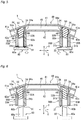
Fig. 1 is a schematic perspective view of a vehicular structure according to a first embodiment of the present invention; -
Fig. 2 is a sectional view of the vehicular structure taken along the line II-II inFig. 1 ; -
Fig. 3 is a sectional view of the vehicular structure taken along the line III-III inFig. 2 ; -
Fig. 4 is a sectional view taken in the same manner asFig. 2 illustrating a first step of joining members according to the first embodiment; -
Fig. 5 is a sectional view taken in the same manner asFig. 2 illustrating a second step of joining the members according to the first embodiment; -
Fig. 6 is a sectional view taken in the same manner asFig. 2 illustrating a third step of joining the members according to the first embodiment; -
Fig. 7 is a sectional view taken in the same manner asFig. 2 illustrating a first modification of the first embodiment; -
Fig. 8 is a sectional view of the vehicular structure taken along the line VIII-VIII inFig. 7 ; -
Fig. 9 is a sectional view taken in the same manner asFig. 2 illustrating a second modification of the first embodiment; -
Fig. 10 is a sectional view of the vehicular structure taken along the line X-X inFig. 9 ; -
Fig. 11 is a sectional view taken in the same manner asFig. 3 illustrating a third modification of the first embodiment; -
Fig. 12 is a sectional view taken in the same manner asFig. 3 illustrating a fourth modification of the first embodiment; -
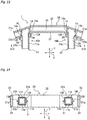
Fig. 13 is a sectional view of a vehicular structure according to a second embodiment of the present invention, taken in the same manner asFig. 2 ; -
Fig. 14 is a sectional view of the vehicular structure taken along line XIV-XIV ofFig. 13 ; -
Fig. 15 is a sectional view taken in the same manner asFig. 13 illustrating a modification of the second embodiment; -
Fig. 16 is a sectional view taken in the same manner asFig. 13 illustrating another modification of the second embodiment; -
Fig. 17 is a sectional view of a vehicular structure according to a third embodiment, taken in the same manner asFig. 2 ; -
Fig. 18 is a sectional view taken in the same manner asFig. 17 illustrating a first step of joining members according to the third embodiment; -
Fig. 19 is a sectional view taken in the same manner asFig. 17 illustrating a second step of joining the members according to the third embodiment; and -
Fig. 20 is a sectional view taken in the same manner asFig. 17 illustrating a third step of joining the members according to the third embodiment. - A vehicular structure according to a first embodiment of the present invention will be described with reference to
Figs. 1 to 3 . The following description uses the terms that indicate particular directions or positions as needed (for example, terms including "upper", "lower", "horizontal", "front", "rear", "side", "end") to facilitate understanding of the invention with reference to the drawings, but the technical scope of the present invention should not be limited by the meaning of these terms. That is, these terms simply indicate directions of a posture of the vehicular structure shown in the attached drawings, and do not necessarily coincide with the directions in an actual use state. In addition, the following descriptions are essentially mere examples, and are not intended to limit the present invention, applied products or applications of the invention. - The following description refers to a width direction of a vehicle as an X-direction, a longitudinal direction of the vehicle as a Y-direction, and a vertical direction of the vehicle as a Z-direction.
- Referring to
Fig. 1 , a bumper reinforcement (vehicular structure) 1 according to the present embodiment includes a pair of bumper stays (first members) 10A, 10B and one bumper beam (second member) 20. - Each of the bumper stays 10A, 10B is a tubular member extending in the Y-direction. Referring also to
Fig. 2 , each of the bumper stays 10A, 10B has a flat surface perpendicular to a longitudinal direction of the bumper stays 10A, 10B at oneend 10a thereof that is mechanically connected to a vehicle skeleton (not shown). Each of the bumper stays 10A, 10B is cut off according to the shape of thebumper beam 20 at theother end 10b thereof that is mechanically connected to thebumper beam 20. Referring also toFig. 3 , each the bumper stays 10A, 10B includes anouter wall unit 11 having a rectangular outer shape with a closed section in a plane perpendicular to the Y-direction (XZ-plane). Theouter wall unit 11 has a pair ofhorizontal walls 11a extending in the X-direction and a pair ofvertical walls 11b extending in the Z-direction such that each of thevertical walls 11b mechanically connects edges of the pair ofhorizontal walls 11a. The bumper stays 10A, 10B respectively includeinward protrusions vertical walls 11b of theouter wall unit 11 of one of the bumper stays 10A, 10B, thevertical wall 11b facing the other one of the bumper stays 10A, 10B. Theinward protrusions vertical walls 11b in the Z-direction toward the inside of the vehicle. The bumper stays 10A, 10B respectively includeoutward protrusions vertical walls 11b of theouter wall unit 11 of one of the bumper stays 10A, 10B, thevertical wall 11b not facing the other one of the bumper stays 10A, 10B. Theoutward protrusions vertical walls 11b in the Z-direction toward the outside of the vehicle. Each of theinward protrusions outward protrusions outer wall unit 11, and has an amount of protrusion approximately twice the thickness of the outer wall unit. Referring toFig. 2 , each of the bumper stays 10A, 10B includes a swellingportion 14 at which theouter wall unit 11 swells outward from its individual one of the bumper stays 10A, 10B. Such bumper stays 10A, 10B may be formed of an aluminum alloy extruded material, for example. - Referring to
Figs. 1 and 2 , thebumper beam 20 is disposed in front of the bumper stays 10 in the Y-direction. Thebumper beam 20 includes afront wall 21 disposed in the XZ-plane, and arear wall 22 disposed in the XZ-plane and rearward in the Y-direction apart from thefront wall 21. Either end of thefront wall 21 has a front inclined-portion 21a extending toward the outside of the vehicle and inclined rearward in the Y-direction when viewed from the Z-direction. Either end of therear wall 22 has a rear inclined-portion (locking wall) 22a extending toward the outside of the vehicle and inclined rearward in the Y-direction when viewed from the Z-direction. Thebumper beam 20 includes anupper wall 23 and alower wall 24 each of which is disposed in a plane perpendicular to the Z-direction (XY-plane) and mechanically connects an edge of thefront wall 21 with an edge of therear wall 22. That is, thebumper beam 20 according to the present embodiment is a tubular member that has aspace 25 surrounded by thefront wall 21, therear wall 22, theupper wall 23, and thelower wall 24, and both ends of which are inclined. Each of the rear inclined-portions 22a has ahole 26 in which theouter wall unit 11 of a corresponding one of the bumper stays 10A, 10B is inserted. Thehole 26 has a rectangular shape similar to the outer shape of theouter wall unit 11 of each of the bumper stays 10A, 10B, and is slightly larger than the outer shape of theouter wall unit 11. Such abumper beam 20 may be formed of, for example, a high-tensile-strength steel. - Referring to
Fig. 2 , the swellingportion 14 of each of the bumper stays 10 is located in thespace 25 of thebumper beam 20, and is in contact with the entire periphery of thehole 26 at anend 14a thereof. - The
inward protrusions outward protrusions portions 22a of therear wall 22 from the rear side in the Y-direction. - A method of forming a
bumper reinforcement 1 according to the present embodiment will be described with reference toFigs. 4 to 6 . - As shown in
Fig. 4 , firststructural members structural member 40 is used to form thebumper beam 20. The first structural members 30 are joined with the secondstructural member 40 by using rubber members 50 (elastic bodies) respectively inserted in the firststructural members pressers 60 for compressing therespective rubber members 50. - Each of the first
structural members outer wall unit 31 having a rectangular outer shape with a closed section in the XZ-plane. Theouter wall unit 31 has a pair of horizontal walls (not shown) extending in the X-direction and a pair ofvertical walls 31b extending in the Z-direction such that each of thevertical walls 31b mechanically connects edges of the pair of horizontal walls. The firststructural members inward protrusions vertical walls 31b of theouter wall unit 31 of one of the firststructural members vertical wall 31b facing the other one of the firststructural members inward protrusions vertical walls 31b in the Z-direction toward the inside of the vehicle. The firststructural members outward protrusions vertical walls 31b of theouter wall unit 31 of one of the firststructural members vertical wall 31b not facing the other one of the firststructural members outward protrusions vertical walls 31b toward the outside of the vehicle. - The second
structural member 40 includes afront wall 41 disposed in the XZ-plane, and arear wall 42 disposed in the XZ-plane and rearward in the Y-direction apart from thefront wall 41. Either end of thefront wall 41 has a front inclined-portion 41a extending toward the outside of the vehicle and inclined rearward in the Y-direction when viewed from the Z-direction. Either end of therear wall 42 has a rear inclined-portion 42a extending toward the outside of the vehicle and inclined rearward in the Y-direction when viewed from the Z-direction. The secondstructural member 40 includes an upper wall and a lower wall (not shown) each of which is disposed in the XY-plane and mechanically connects an edge of thefront wall 41 with an edge of therear wall 42. That is, the secondstructural member 40 according to the present embodiment is a tubular member that has aspace 45 surrounded by thefront wall 41, therear wall 42, the upper wall, and the lower wall, and both ends of which are inclined. Each of the rear inclined-portions 42a has ahole 46 in which theouter wall unit 31 of a corresponding one of the firststructural member hole 46 has a rectangular shape similar to the outer shape of theouter wall unit 31 of each of the firststructural members outer wall unit 31. - Each of the
rubber members 50 has a shape of a quadrangular prism extending in the Y-direction. The outer shape of eachrubber member 50 is slightly smaller than the inner shape of each of the firststructural members rubber members 50 can be inserted in the firststructural members rubber member 50 has a flat surface inclined with respect to the longitudinal direction of therubber members 50 corresponding to the shape of the secondstructural member 40. A material of therubber members 50 is preferably urethane rubber, chloroprene rubber, CNR (rubber formed of chloroprene rubber and nitrile rubber), or silicone rubber, for example. The hardness of therubber members 50 is preferably 30 or more in Shore A. - The
pressers 60 are attached to a press device or the like (not shown), and are configured to compress therubber members 50 respectively in the Y-direction by being driven by the press device. Each of thepressers 60 has aprojection 60a. Theprojection 60a is a part to press a corresponding one of therubber members 50. Apressing surface 60b, which is an end surface of theprojection 60a, has a flat surface inclined with respect to the longitudinal direction of therubber members 50 corresponding to the shape of eachrubber member 50. - First, as shown in
Fig. 4 , the firststructural members holes 46 provided in the rear inclined-portions 42a until theinward protrusions outward protrusions portions 42a of therear wall 42 of the secondstructural member 40. Then, therubber members 50 are respectively inserted in the firststructural members - Next, as shown in
Fig. 5 , theprojections 60a of thepressers 60 are respectively inserted in the firststructural members rubber members 50 in the Y-direction to cause therubber members 50 to swell in a direction orthogonal to the compression direction, thereby expanding the firststructural members structural members structural member 40. Each of the firststructural members portion 34 disposed in aninternal space 45 of the secondstructural member 40. Anend 34a of the swellingportion 34 is prevented from being deformed due to a corresponding one of theholes 46 of the secondstructural member 40. Theouter wall units 31 of the firststructural members inward protrusions outward protrusions inward protrusions outward protrusions - After the first
structural members structural member 40, compression by thepressers 60 is released as shown inFig. 6 . Therubber members 50 that have been released from a compression force are restored to their original shapes by their own elasticity. Therefore, therubber members 50 can be easily removed from the firststructural members - The
bumper reinforcement 1 of the present embodiment has the following features. - Each of the end surfaces of the
inward protrusions outward protrusions outer wall units 11 of the bumper stays 10A, 10B are respectively inserted in theholes 26 of thebumper beam 20, theinward protrusions outward protrusions portions 22a from the rear side in the Y-direction. Therefore, in the case where a force is applied to thebumper reinforcement 1 from the front side in the Y-direction (see the broken arrow F1 inFig. 2 ), theinward protrusions outward protrusions portions 22a to support part of the force, thereby reducing the force acting on the joint portions. This can enhance the joining strength between the bumper stays 10A, 10B and thebumper beam 20 with respect to a force in the Y-direction, thereby preventing the joint portions between the bumper stays 10A, 10B and thebumper beam 20 from being released. As a result, the bumper stays 10A, 10B can be prevented from penetrating thebumper beam 20. - In addition, in the case where a force in the X-direction is applied to the
bumper reinforcement 1, theinward protrusions outward protrusions portions 22a to support part of the force, thereby reducing the force acting on the joint portions. For example, in the case where a force in the X-direction (see the dashed arrow F2) is applied by an offset collision to the left front inclined-portion 21a inFig. 2 , theoutward protrusions 13A and theinward protrusion 12B come into contact with the rear inclined-portions 22a to support part of the force, thereby reducing the force acting on the joint portions. Similarly, in the case where a force in the X-direction (see the dashed arrow F3) is applied by an offset collision to the right front inclined-portion 21a inFig. 2 , theinward protrusions 12A and theoutward protrusion 13B come into contact with the rear inclined-portions 22a to support part of the force, thereby reducing the force applied to the joint portions. This can enhance the joining strength between the bumper stays 10A, 10B and thebumper beam 20 with respect to a force in the X-direction, thereby preventing the joint portions between the bumper stays 10A, 10B and thebumper beam 20 from being released. As a result, the bumper stays 10A, 10B and thebumper beam 20 can be prevented from falling in the X-direction. - Furthermore, according to the present embodiment, in the case where a collision force in the Y-direction is applied to the
bumper reinforcement 1, the bumper stays 10A, 10B can be prevented from penetrating thebumper beam 20 as described above, so that the bumper stays 10A, 10B are crushed in a collision. The crush of the bumper stays 10A, 10B absorbs the energy of the collision, so that the collision force can be distributed before reaching the cabin, and thus a driver can be protected safely. Further, in the case where a collision force in the X-direction is applied to thebumper reinforcement 1, the bumper stays 10A, 10B and thebumper beam 20 can be prevented from falling (falling sideways) as described above, which maintains an absorption capacity for collision energy of thebumper reinforcement 1. Thebumper reinforcement 1 has been exemplified as an application of the present invention as described above, but the present invention can be applied to any vehicular structure that includes an expanded-tube joint, as well as thebumper reinforcement 1. - Hereinafter, modifications of the
bumper reinforcement 1 according to the present embodiment will be described with reference toFigs. 7 to 12 . -
Figs. 7 and 8 show a first modification in which the bumper stays 10A, 10B respectively includeinward protrusions portions 14 at portions of the pair ofvertical walls 11b where theinward protrusions 12A, 12b are not provided, in theouter wall unit 11 of each of the bumper stays 10A, 10B. - In the case where a force in the X-direction is applied to the
bumper reinforcement 1, theinward protrusions portions 22a to support part of the force, thereby reducing the force acting on the joint portions. For example, in the case where a force in the X-direction (see the dashed arrow F2) is applied by an offset collision to the left front inclined-portion 21a inFig. 7 , theinward protrusion 12B comes into contact with a corresponding one of the rear inclined-portions 22a to support part of the force, thereby reducing the force acting on the joint portions. Similarly, in the case where a force in the X-direction (see the dashed arrow F3) is applied by an offset collision to the right front inclined-portion 21a inFig. 7 , theinward protrusion 12A comes into contact with a corresponding one of the rear inclined-portions 22a to support part of the force, thereby reducing the force applied to the joint portions. This can enhance the joining strength between the bumper stays 10A, 10B and thebumper beam 20 with respect to a force in the X-direction, thereby preventing the joint portions between the bumper stays 10A, 10B and thebumper beam 20 from being released. As a result, the bumper stays 10A, 10B and thebumper beam 20 can be prevented from falling in the X-direction. -
Figs. 9 and 10 shows a second modification in which the bumper stays 10A, 10B respectively includeoutward protrusions portions 14 at portions of the pair ofvertical walls 11b where theoutward protrusions outer wall unit 1 1 of each of the bumper stays 10A, 10B. - In the case where a force in the X-direction is applied to the
bumper reinforcement 1, theoutward protrusions portions 22a to support part of the force, thereby reducing the force acting on the joint portions. For example, in the case where a force in the X-direction (see the dashed arrow F2) is applied by an offset collision to the left front inclined-portion 21a inFig. 9 , theoutward protrusion 13A comes into contact with a corresponding one of the rear inclined-portions 22a to support part of the force, thereby reducing the force acting on the joint portions. Similarly, in the case where a force in the X-direction (see the dashed arrow F3) is applied by an offset collision to the right front inclined-portion 21a inFig. 9 , theoutward protrusion 13B comes into contact with a corresponding one of the rear inclined-portions 22a to support part of the force, thereby reducing the force acting on the joint portions. This can enhance the joining strength between the bumper stays 10A, 10B and thebumper beam 20 with respect to a force in the X-direction, thereby preventing the joint portions between the bumper stays 10A, 10B and thebumper beam 20 from being released. As a result, the bumper stays 10A, 10B and thebumper beam 20 can be prevented from falling in the X-direction. -
Fig. 11 shows a third modification in which each of the bumper stays 10A, 10B includes a pair ofvertical protrusions 15. Eachvertical protrusion 15 protrudes in the Z-direction from a substantially middle portion in the X-direction of one of the pair ofhorizontal walls 11a. -
Fig. 12 shows a fourth modification in which each of the bumper stays 10A, 10B includes anouter wall unit 11 having a circular outer shape with a closed section in the XZ-plane. Theouter wall unit 11 has an axial center C1 extending in the Y-direction. The bumper stays 10A, 10B respectively includeinward protrusions outer wall unit 11 disposed inwardly of the vehicle from the axial center C1. The bumper stays 10A, 10B respectively includeoutward protrusions outer wall unit 11 disposed outwardly of the vehicle from the axial center C1. Theinward protrusions outward protrusions - In the second and the third embodiments described below, the same or similar elements as or to those of the first embodiment are denoted by the same reference numerals, and the detailed description thereof is omitted. Furthermore, in these embodiments, the same effects as in the first embodiment are exerted except for the points specifically mentioned.
- A second embodiment of the present invention will be described with reference to
Figs. 13 and 14 . - With reference to
Figs. 13 and 14 , the bumper stays 10A, 10B of the present embodiment haveinward protrusions outward protrusions inward protrusions outward protrusions inward protrusions outward protrusions bumper beam 20, but do not have theinward protrusions outward protrusions - According to the present embodiment, the bumper stays 10A, 10B can be reduced in weight because of the portions without the
inward protrusions outward protrusions inward protrusions outward protrusions bumper beam 20. As a result, an absorption capacity for collision energy of the bumper stays 10A, 10B can be enhanced. - Hereinafter, modifications of the present embodiment will be described with reference to
Figs. 15 and 16 . -
Fig. 15 shows a modification in which each of the bumper stays 10A, 10B includes a mountingplate 16 at their rear ends in the Y-direction for attaching thebumper reinforcement 1 to the vehicle body. The bumper stays 10A, 10B respectively have theinward protrusions outward protrusions bumper beam 20 and near the mountingplates 16, but do not have theinward protrusions outward protrusions -
Fig. 16 shows a modification in which the amounts of protrusion of theinward protrusions outward protrusions - A third embodiment of the present invention will be described with reference to
Fig. 17 . - Referring to
Fig. 17 , the bumper stays 10A, 10B penetrate thebumper beam 20. Each of the bumper stays 10A, 10B has a flat surface perpendicular to the Y-direction at both ends thereof. Each of the front inclined-portions 21a of thebumper beam 20 includes ahole 27 that is concentric with and has the same shape as a corresponding one of theholes 26 of the rear inclined-portions 22a. The bumper stays 10A, 10B are respectively inserted in theholes 26 of the rear inclined-portions 22a and in theholes 27 of the front inclined-portions 21a of thebumper beam 20. Theouter wall unit 11 of each of the bumper stays 10A, 10B includes swellingportions 14 formed inside thespace 25 and on the front side in the Y-direction of thebumper beam 20. - Hereinafter, a method for forming the
bumper reinforcement 1 according to the present embodiment will be described with reference toFigs. 18 to 20 . - Referring to
Fig. 18 , each of the firststructural members structural member 40 includes at each of their front inclined-portions 41a ahole 47 that is concentric with and has the same shape as a corresponding one of theholes 46 of the rear inclined-portions 42a. The firststructural members holes 46 of the rear inclined-portions 42a, and then in theholes 47 of the front inclined-portions 41a of the secondstructural member 40. Each of therubber members 50 has flat surfaces perpendicular to the Y-direction at both ends thereof. Thepressers 60 are disposed corresponding to either end of the firststructural members pressers 60 are used for each one of the firststructural members - As shown in
Fig. 19 , in a crimping step according to the present embodiment, thepressers 60 on one side are fixed and thepressers 60 on the other side are inserted in the respective firststructural members structural members pressers 60 compress therespective rubber members 50 in the Y-direction so thatrubber members 50 expand in a direction orthogonal to the compression direction, thereby expanding theouter wall unit 31 of each of the firststructural members outer wall unit 31 of each of the firststructural members holes structural member 40. Accordingly, each one of the firststructural members structural member 40 at at least two places (i.e., twoholes 46, 47) in the present embodiment. - As shown in
Fig. 20 , compression by thepressers 60 is released after crimping. Therubber members 50 that have been released from a compression force are restored to their original shapes by their own elasticity. Therefore, therubber members 50 can be easily removed from the firststructural members - According to the present embodiment, a through hole penetrating the
bumper beam 20 can be formed when theholes bumper beam 20. In view of a machining process, forming a through hole is easy as compared with forming a halfway hole (or a half through-hole). In addition, since each of the firststructural members structural member 40, therubber members 50 can be inserted from either end of each of the firststructural members structural members structural member 40 at two places, thereby enhancing the joining strength as compared with the configurations of the above described other embodiments. - The present invention has been described above with reference to the preferred embodiments, but the present invention is not limited to the specific embodiments, and various modifications can be made within the scope of the subject matter of the present invention described in the claims.
- For example, the inward protrusions, the outward protrusions, and the vertical protrusions may be formed separately from the bumper stays.
- The cross-sectional shape of each bumper stay is not limited to a rectangle or a circle, and may also be, for example, a polygon.
- In addition, one bumper stay may include two or more inward protrusions, two or more outward protrusions, and two or more vertical protrusions.
- The bumper beam is not limited to a steel material, such as a high-tensile-strength steel, and may be made of, for example, an aluminum alloy. That is, both the bumper beam and the bumper stays may be made of an aluminum material.
- 1: bumper reinforcement (vehicular structure), 10A; 10B: bumper stay (first member), 11: outer wall unit, 11a: horizontal wall, 11b: vertical wall, 12A; 12B: inward protrusion, 13A; 13B: outward protrusion, 14: swelling portion, 15: vertical protrusion, 16: mounting plate, 20: bumper beam (second member), 21: front wall, 21a: front inclined-portion, 22: rear wall, 22a: rear inclined-portion (locking wall), 23: upper wall, 24: lower wall, 25: space, 26: hole, 27: hole, 30A; 30B: first structural member, 31b: vertical wall, 32A; 32B: inward protrusion, 33A; 33B: outward protrusion, 34: swelling portion, 40: second structural member, 41: front wall, 41a: front inclined-portion, 42: rear wall, 42a: rear inclined-portion, 43: upper wall, 44: lower wall, 45: space, 46: hole, 47: hole, 50: rubber member (elastic body), 60: presser, 60a: projection, 60b: pressing surface
Claims (8)
- A vehicular structure comprising:a first member formed in a tubular shape and having a protrusion on an outer periphery thereof; anda second member formed in a tubular shape and having a locking wall with a hole in which the first member is inserted,wherein the first member is expanded at a portion thereof inserted in the hole of the second member and joined to the second member, andwherein the protrusion is in contact with the locking wall of the second member.
- The vehicular structure according to claim 1, wherein the hole penetrates the locking wall in a direction intersecting a longitudinal direction of the second member, and
wherein the protrusion protrudes in the longitudinal direction. - The vehicular structure according to claim 1 or 2,
wherein the protrusion extends in an axial direction of the first member. - The vehicular structure according to claim 3,
wherein a protruded amount of the protrusion has distribution in the axial direction of the first member of the protrusion. - The vehicular structure according to claim 1 or 2,
wherein the first member is a bumper stay for a vehicle, and the second member is a bumper beam for a vehicle. - The vehicular structure according to claim 1 or 2,
wherein each of the first member and the second member is made of an aluminum material. - The vehicular structure according to claim 1 or 2,
wherein a material of the first member is different from a material of the second member. - The vehicular structure according to claim 7,
wherein the first member is made of an aluminum material, and the second member is made of a steel material.
Applications Claiming Priority (2)
| Application Number | Priority Date | Filing Date | Title |
|---|---|---|---|
| JP2017059794A JP6760873B2 (en) | 2017-03-24 | 2017-03-24 | Vehicle structure |
| PCT/JP2018/009770 WO2018173859A1 (en) | 2017-03-24 | 2018-03-13 | Vehicular structure |
Publications (3)
| Publication Number | Publication Date |
|---|---|
| EP3604045A1 true EP3604045A1 (en) | 2020-02-05 |
| EP3604045A4 EP3604045A4 (en) | 2020-11-04 |
| EP3604045B1 EP3604045B1 (en) | 2025-10-01 |
Family
ID=63584506
Family Applications (1)
| Application Number | Title | Priority Date | Filing Date |
|---|---|---|---|
| EP18770206.3A Active EP3604045B1 (en) | 2017-03-24 | 2018-03-13 | Vehicular structure |
Country Status (4)
| Country | Link |
|---|---|
| US (1) | US10974673B2 (en) |
| EP (1) | EP3604045B1 (en) |
| JP (1) | JP6760873B2 (en) |
| WO (1) | WO2018173859A1 (en) |
Cited By (2)
| Publication number | Priority date | Publication date | Assignee | Title |
|---|---|---|---|---|
| US11590911B2 (en) | 2019-07-26 | 2023-02-28 | Shape Corp. | Hybrid bumper assembly for a vehicle |
| EP4104947A4 (en) * | 2020-04-08 | 2023-08-09 | Kabushiki Kaisha Kobe Seiko Sho (Kobe Steel, Ltd.) | STRUCTURE PRODUCTION PROCESS |
Families Citing this family (12)
| Publication number | Priority date | Publication date | Assignee | Title |
|---|---|---|---|---|
| DE102015117700A1 (en) * | 2015-10-16 | 2017-04-20 | Magna International Inc. | Cross member and method for producing a cross member |
| JP7410398B2 (en) * | 2020-03-30 | 2024-01-10 | 日本製鉄株式会社 | Manufacturing method of riveted joint structure, riveted joint structure and automobile parts |
| JP7289285B2 (en) * | 2020-11-02 | 2023-06-09 | 株式会社神戸製鋼所 | Member joining method and joined body |
| JP1693926S (en) * | 2021-01-15 | 2021-08-30 | Automotive bumper reinforcement | |
| JP1700400S (en) * | 2021-01-15 | 2021-11-22 | ||
| JP1700539S (en) * | 2021-01-15 | 2021-11-22 | ||
| JP1700540S (en) * | 2021-01-15 | 2021-11-22 | ||
| JP1693924S (en) * | 2021-01-15 | 2021-08-30 | Automotive bumper reinforcement | |
| JP1693925S (en) * | 2021-01-15 | 2021-08-30 | Automotive bumper reinforcement | |
| JP1700401S (en) * | 2021-01-15 | 2021-11-22 | ||
| JP1693927S (en) * | 2021-01-15 | 2021-08-30 | Automotive bumper reinforcement | |
| CN119522174A (en) | 2022-07-08 | 2025-02-25 | 株式会社力森诺科 | Manufacturing method of automobile structural parts |
Family Cites Families (27)
| Publication number | Priority date | Publication date | Assignee | Title |
|---|---|---|---|---|
| US6361092B1 (en) * | 2000-11-13 | 2002-03-26 | Daimlerchrysler Corporation | Automotive frame bumper interface for discriminated deceleration response |
| JP2002155981A (en) * | 2000-11-21 | 2002-05-31 | Aisin Seiki Co Ltd | Shock absorbing member and bumper |
| JP4386237B2 (en) * | 2003-02-04 | 2009-12-16 | 株式会社神戸製鋼所 | Bumper reinforcement and stay mounting structure and bumper structure |
| JP4219189B2 (en) * | 2003-02-28 | 2009-02-04 | 株式会社アステア | Bumper reinforcement support structure for body members |
| JP2007284039A (en) * | 2006-03-22 | 2007-11-01 | Kobe Steel Ltd | Bumper structure and frame structure |
| JP4895739B2 (en) * | 2006-09-16 | 2012-03-14 | 株式会社神戸製鋼所 | Bumper structure |
| JP5177397B2 (en) * | 2008-03-31 | 2013-04-03 | 株式会社神戸製鋼所 | Bumper structure |
| JP5049210B2 (en) * | 2008-06-25 | 2012-10-17 | 株式会社神戸製鋼所 | Bumper stay |
| DE112010006033T5 (en) * | 2009-10-19 | 2013-08-29 | Showa Denko K.K. | Vehicle bumper beam and method of making the same |
| JP5587698B2 (en) * | 2010-07-30 | 2014-09-10 | アイシン精機株式会社 | Bumper device for vehicle |
| JP5821601B2 (en) * | 2011-12-13 | 2015-11-24 | トヨタ自動車株式会社 | Body front structure |
| JP5826710B2 (en) * | 2012-06-05 | 2015-12-02 | 株式会社神戸製鋼所 | Manufacturing method of automobile bumper structure |
| JP5867470B2 (en) * | 2013-09-11 | 2016-02-24 | トヨタ自動車株式会社 | Vehicle front structure |
| JP2016078492A (en) * | 2014-10-10 | 2016-05-16 | トヨタ自動車東日本株式会社 | Vehicle front structure |
| JP6070677B2 (en) * | 2014-10-31 | 2017-02-01 | トヨタ自動車株式会社 | Vehicle front structure |
| JP6454233B2 (en) | 2015-02-06 | 2019-01-16 | 株式会社神戸製鋼所 | Member joining method |
| JP6256432B2 (en) * | 2015-08-21 | 2018-01-10 | トヨタ自動車株式会社 | Vehicle skeleton structure |
| JP6573517B2 (en) * | 2015-09-28 | 2019-09-11 | 株式会社神戸製鋼所 | Bumper member joining method and bumper structure |
| JP6215891B2 (en) * | 2015-10-15 | 2017-10-18 | 本田技研工業株式会社 | Body structure with shock absorbing member |
| JP2018100055A (en) * | 2016-12-21 | 2018-06-28 | トヨタ自動車株式会社 | Energy absorption structure |
| JP6734232B2 (en) * | 2017-03-17 | 2020-08-05 | 株式会社神戸製鋼所 | Method for joining members and joined body |
| JP6766776B2 (en) * | 2017-08-21 | 2020-10-14 | トヨタ車体株式会社 | Vehicle bumper |
| JP6706600B2 (en) * | 2017-09-05 | 2020-06-10 | 株式会社神戸製鋼所 | Bumper system |
| DE102017222081A1 (en) * | 2017-12-06 | 2019-06-06 | Volkswagen Aktiengesellschaft | Bumper crossmember system for a motor vehicle, modular system and motor vehicle with such a bumper crossmember system |
| JP7072389B2 (en) * | 2018-01-15 | 2022-05-20 | 株式会社神戸製鋼所 | Vehicle structure and its manufacturing method |
| US20190264769A1 (en) * | 2018-02-27 | 2019-08-29 | GM Global Technology Operations LLC | Composite energy-absorbing assembly having discrete energy-absorbing elements supported by a carrier plate |
| JP2019214289A (en) * | 2018-06-12 | 2019-12-19 | 本田技研工業株式会社 | Vehicle front structure |
-
2017
- 2017-03-24 JP JP2017059794A patent/JP6760873B2/en active Active
-
2018
- 2018-03-13 EP EP18770206.3A patent/EP3604045B1/en active Active
- 2018-03-13 WO PCT/JP2018/009770 patent/WO2018173859A1/en not_active Ceased
- 2018-03-13 US US16/495,299 patent/US10974673B2/en active Active
Cited By (4)
| Publication number | Priority date | Publication date | Assignee | Title |
|---|---|---|---|---|
| US11590911B2 (en) | 2019-07-26 | 2023-02-28 | Shape Corp. | Hybrid bumper assembly for a vehicle |
| US11766976B2 (en) | 2019-07-26 | 2023-09-26 | Shape Corp. | Hybrid bumper assembly for a vehicle |
| EP4104947A4 (en) * | 2020-04-08 | 2023-08-09 | Kabushiki Kaisha Kobe Seiko Sho (Kobe Steel, Ltd.) | STRUCTURE PRODUCTION PROCESS |
| US12157426B2 (en) | 2020-04-08 | 2024-12-03 | Kobe Steel, Ltd. | Method for producing structure |
Also Published As
| Publication number | Publication date |
|---|---|
| US10974673B2 (en) | 2021-04-13 |
| JP2018161946A (en) | 2018-10-18 |
| US20210009058A1 (en) | 2021-01-14 |
| EP3604045A4 (en) | 2020-11-04 |
| JP6760873B2 (en) | 2020-09-23 |
| EP3604045B1 (en) | 2025-10-01 |
| WO2018173859A1 (en) | 2018-09-27 |
Similar Documents
| Publication | Publication Date | Title |
|---|---|---|
| EP3604045B1 (en) | Vehicular structure | |
| US11110874B2 (en) | Method for joining members and joined body | |
| US10604092B2 (en) | Bumper beam structure | |
| US10293857B2 (en) | Reach vehicle-body structure of vehicle | |
| EP2412582B1 (en) | Bumper reinforcement and bumper device for vehicle | |
| US11279408B2 (en) | Hollow member | |
| KR101166641B1 (en) | Bumper beam | |
| EP2821325A1 (en) | Vehicular shock absorbing device and vehicular shock absorbing structure | |
| JP6973517B2 (en) | Structural members for vehicles | |
| US10286955B2 (en) | Rear vehicle-body structure of vehicle | |
| US20190152415A1 (en) | Impact energy absorbing apparatus | |
| US8888151B2 (en) | Vehicle body rear structure | |
| JP6986469B2 (en) | Structural members for vehicles | |
| US11148719B2 (en) | Bumper system | |
| JP5094544B2 (en) | Bumper structure | |
| JP4413650B2 (en) | Bonding structure for automotive frame materials | |
| JP2023177779A (en) | Vehicle side structure | |
| CN116890722B (en) | Seat Cushion Frame | |
| JP2000053017A (en) | Energy absorption structure of automobile | |
| JP2005104235A (en) | Automotive bumper equipment | |
| JP2005254829A (en) | Bumper stay and bumper structure | |
| JP4543778B2 (en) | Shock absorbing member | |
| US9656692B2 (en) | Vehicle chassis structure | |
| JP2006001449A (en) | Bumper structure for passenger car |
Legal Events
| Date | Code | Title | Description |
|---|---|---|---|
| STAA | Information on the status of an ep patent application or granted ep patent |
Free format text: STATUS: THE INTERNATIONAL PUBLICATION HAS BEEN MADE |
|
| PUAI | Public reference made under article 153(3) epc to a published international application that has entered the european phase |
Free format text: ORIGINAL CODE: 0009012 |
|
| STAA | Information on the status of an ep patent application or granted ep patent |
Free format text: STATUS: REQUEST FOR EXAMINATION WAS MADE |
|
| 17P | Request for examination filed |
Effective date: 20190911 |
|
| AK | Designated contracting states |
Kind code of ref document: A1 Designated state(s): AL AT BE BG CH CY CZ DE DK EE ES FI FR GB GR HR HU IE IS IT LI LT LU LV MC MK MT NL NO PL PT RO RS SE SI SK SM TR |
|
| AX | Request for extension of the european patent |
Extension state: BA ME |
|
| DAV | Request for validation of the european patent (deleted) | ||
| DAX | Request for extension of the european patent (deleted) | ||
| A4 | Supplementary search report drawn up and despatched |
Effective date: 20201005 |
|
| RIC1 | Information provided on ipc code assigned before grant |
Ipc: B60R 19/04 20060101ALI20200929BHEP Ipc: B60R 19/34 20060101ALI20200929BHEP Ipc: B60R 19/24 20060101AFI20200929BHEP |
|
| STAA | Information on the status of an ep patent application or granted ep patent |
Free format text: STATUS: EXAMINATION IS IN PROGRESS |
|
| 17Q | First examination report despatched |
Effective date: 20230209 |
|
| GRAP | Despatch of communication of intention to grant a patent |
Free format text: ORIGINAL CODE: EPIDOSNIGR1 |
|
| STAA | Information on the status of an ep patent application or granted ep patent |
Free format text: STATUS: GRANT OF PATENT IS INTENDED |
|
| INTG | Intention to grant announced |
Effective date: 20250428 |
|
| GRAS | Grant fee paid |
Free format text: ORIGINAL CODE: EPIDOSNIGR3 |
|
| GRAA | (expected) grant |
Free format text: ORIGINAL CODE: 0009210 |
|
| STAA | Information on the status of an ep patent application or granted ep patent |
Free format text: STATUS: THE PATENT HAS BEEN GRANTED |
|
| P01 | Opt-out of the competence of the unified patent court (upc) registered |
Free format text: CASE NUMBER: UPC_APP_2438_3604045/2025 Effective date: 20250805 |
|
| AK | Designated contracting states |
Kind code of ref document: B1 Designated state(s): AL AT BE BG CH CY CZ DE DK EE ES FI FR GB GR HR HU IE IS IT LI LT LU LV MC MK MT NL NO PL PT RO RS SE SI SK SM TR |
|
| REG | Reference to a national code |
Ref country code: GB Ref legal event code: FG4D Ref country code: CH Ref legal event code: F10 Free format text: ST27 STATUS EVENT CODE: U-0-0-F10-F00 (AS PROVIDED BY THE NATIONAL OFFICE) Effective date: 20251001 |
|
| REG | Reference to a national code |
Ref country code: IE Ref legal event code: FG4D |
|
| REG | Reference to a national code |
Ref country code: DE Ref legal event code: R096 Ref document number: 602018086034 Country of ref document: DE |
|
| REG | Reference to a national code |
Ref country code: NL Ref legal event code: MP Effective date: 20251001 |
|
| REG | Reference to a national code |
Ref country code: AT Ref legal event code: MK05 Ref document number: 1842226 Country of ref document: AT Kind code of ref document: T Effective date: 20251001 |
|
| PG25 | Lapsed in a contracting state [announced via postgrant information from national office to epo] |
Ref country code: NL Free format text: LAPSE BECAUSE OF FAILURE TO SUBMIT A TRANSLATION OF THE DESCRIPTION OR TO PAY THE FEE WITHIN THE PRESCRIBED TIME-LIMIT Effective date: 20251001 |
|
| PG25 | Lapsed in a contracting state [announced via postgrant information from national office to epo] |
Ref country code: ES Free format text: LAPSE BECAUSE OF FAILURE TO SUBMIT A TRANSLATION OF THE DESCRIPTION OR TO PAY THE FEE WITHIN THE PRESCRIBED TIME-LIMIT Effective date: 20251001 |
|
| REG | Reference to a national code |
Ref country code: LT Ref legal event code: MG9D |
|
| PG25 | Lapsed in a contracting state [announced via postgrant information from national office to epo] |
Ref country code: NO Free format text: LAPSE BECAUSE OF FAILURE TO SUBMIT A TRANSLATION OF THE DESCRIPTION OR TO PAY THE FEE WITHIN THE PRESCRIBED TIME-LIMIT Effective date: 20260101 |
|
| PGFP | Annual fee paid to national office [announced via postgrant information from national office to epo] |
Ref country code: DE Payment date: 20260330 Year of fee payment: 9 |
|
| PG25 | Lapsed in a contracting state [announced via postgrant information from national office to epo] |
Ref country code: FI Free format text: LAPSE BECAUSE OF FAILURE TO SUBMIT A TRANSLATION OF THE DESCRIPTION OR TO PAY THE FEE WITHIN THE PRESCRIBED TIME-LIMIT Effective date: 20251001 Ref country code: HR Free format text: LAPSE BECAUSE OF FAILURE TO SUBMIT A TRANSLATION OF THE DESCRIPTION OR TO PAY THE FEE WITHIN THE PRESCRIBED TIME-LIMIT Effective date: 20251001 Ref country code: AT Free format text: LAPSE BECAUSE OF FAILURE TO SUBMIT A TRANSLATION OF THE DESCRIPTION OR TO PAY THE FEE WITHIN THE PRESCRIBED TIME-LIMIT Effective date: 20251001 |
|
| PG25 | Lapsed in a contracting state [announced via postgrant information from national office to epo] |
Ref country code: RS Free format text: LAPSE BECAUSE OF FAILURE TO SUBMIT A TRANSLATION OF THE DESCRIPTION OR TO PAY THE FEE WITHIN THE PRESCRIBED TIME-LIMIT Effective date: 20260101 |
|
| PG25 | Lapsed in a contracting state [announced via postgrant information from national office to epo] |
Ref country code: IS Free format text: LAPSE BECAUSE OF FAILURE TO SUBMIT A TRANSLATION OF THE DESCRIPTION OR TO PAY THE FEE WITHIN THE PRESCRIBED TIME-LIMIT Effective date: 20260201 |
|
| PG25 | Lapsed in a contracting state [announced via postgrant information from national office to epo] |
Ref country code: CZ Free format text: LAPSE BECAUSE OF FAILURE TO SUBMIT A TRANSLATION OF THE DESCRIPTION OR TO PAY THE FEE WITHIN THE PRESCRIBED TIME-LIMIT Effective date: 20251001 Ref country code: PT Free format text: LAPSE BECAUSE OF FAILURE TO SUBMIT A TRANSLATION OF THE DESCRIPTION OR TO PAY THE FEE WITHIN THE PRESCRIBED TIME-LIMIT Effective date: 20260202 |
|
| PG25 | Lapsed in a contracting state [announced via postgrant information from national office to epo] |
Ref country code: PL Free format text: LAPSE BECAUSE OF FAILURE TO SUBMIT A TRANSLATION OF THE DESCRIPTION OR TO PAY THE FEE WITHIN THE PRESCRIBED TIME-LIMIT Effective date: 20251001 |
|
| PG25 | Lapsed in a contracting state [announced via postgrant information from national office to epo] |
Ref country code: LV Free format text: LAPSE BECAUSE OF FAILURE TO SUBMIT A TRANSLATION OF THE DESCRIPTION OR TO PAY THE FEE WITHIN THE PRESCRIBED TIME-LIMIT Effective date: 20251001 |