EP3604021A1 - Lifting device for current collector - Google Patents
Lifting device for current collector Download PDFInfo
- Publication number
- EP3604021A1 EP3604021A1 EP17912660.2A EP17912660A EP3604021A1 EP 3604021 A1 EP3604021 A1 EP 3604021A1 EP 17912660 A EP17912660 A EP 17912660A EP 3604021 A1 EP3604021 A1 EP 3604021A1
- Authority
- EP
- European Patent Office
- Prior art keywords
- current collector
- driving
- linkage mechanism
- bar linkage
- lifting device
- Prior art date
- Legal status (The legal status is an assumption and is not a legal conclusion. Google has not performed a legal analysis and makes no representation as to the accuracy of the status listed.)
- Withdrawn
Links
Images

Classifications
-
- B—PERFORMING OPERATIONS; TRANSPORTING
- B60—VEHICLES IN GENERAL
- B60L—PROPULSION OF ELECTRICALLY-PROPELLED VEHICLES; SUPPLYING ELECTRIC POWER FOR AUXILIARY EQUIPMENT OF ELECTRICALLY-PROPELLED VEHICLES; ELECTRODYNAMIC BRAKE SYSTEMS FOR VEHICLES IN GENERAL; MAGNETIC SUSPENSION OR LEVITATION FOR VEHICLES; MONITORING OPERATING VARIABLES OF ELECTRICALLY-PROPELLED VEHICLES; ELECTRIC SAFETY DEVICES FOR ELECTRICALLY-PROPELLED VEHICLES
- B60L5/00—Current collectors for power supply lines of electrically-propelled vehicles
- B60L5/18—Current collectors for power supply lines of electrically-propelled vehicles using bow-type collectors in contact with trolley wire
- B60L5/22—Supporting means for the contact bow
- B60L5/28—Devices for lifting and resetting the collector
- B60L5/30—Devices for lifting and resetting the collector using springs
-
- B—PERFORMING OPERATIONS; TRANSPORTING
- B60—VEHICLES IN GENERAL
- B60L—PROPULSION OF ELECTRICALLY-PROPELLED VEHICLES; SUPPLYING ELECTRIC POWER FOR AUXILIARY EQUIPMENT OF ELECTRICALLY-PROPELLED VEHICLES; ELECTRODYNAMIC BRAKE SYSTEMS FOR VEHICLES IN GENERAL; MAGNETIC SUSPENSION OR LEVITATION FOR VEHICLES; MONITORING OPERATING VARIABLES OF ELECTRICALLY-PROPELLED VEHICLES; ELECTRIC SAFETY DEVICES FOR ELECTRICALLY-PROPELLED VEHICLES
- B60L2200/00—Type of vehicles
- B60L2200/26—Rail vehicles
Definitions
- the present application relates to the technical field of current collectors, and in particular to a lifting device for a current collector.
- the first elastic member is a first spring, and an axis of the first spring is parallel to an axis of the first telescopic driving shaft.
- the second driving member is an unlocking cylinder, and an end of the second spring away from the locking hook is fixed to the unlocking cylinder.
- the crank of the four-bar linkage mechanism 2 is driven by the first driving member 3 to rotate in the direction for lowering the current collector (that is, a counterclockwise direction in Figure 3 ), and the first elastic member 1 is deformed by force; when the crank is rotated to the position where the current collector is lowered, the four-bar linkage mechanism 2 is locked in the position-limiting member, and is held at a locked position by the elastic force of the second elastic member 5, as shown in Figures 1 and 2 , thereby realizing lowering of the current collector.
- the position-limiting member is a locking hook 6, a bottom end of the locking hook 6 is hinged to the baseplate 10, and a top end of the locking hook 6 is able to hook the positioning shaft 11.
- the positioning shaft 11 is locked by the locking hook 6, and the locking hook 6 is driven by the second driving member 4 to rotate around a hinge point at the bottom end, thereby achieving the release of the positioning shaft 11, and the structure is simple.
- the position-limiting member may also be a clamping plate arranged in a horizontal direction, and the clamping plate can be tightened downward in a vertical direction by the elastic force of the second elastic member, thereby achieving a same effect of locking the positioning shaft.
Landscapes
- Engineering & Computer Science (AREA)
- Power Engineering (AREA)
- Transportation (AREA)
- Mechanical Engineering (AREA)
- Current-Collector Devices For Electrically Propelled Vehicles (AREA)
- Holders For Apparel And Elements Relating To Apparel (AREA)
Abstract
Description
- The application claims the priority to Chinese Patent Application No.
201710418667.7 - The present application relates to the technical field of current collectors, and in particular to a lifting device for a current collector.
- At present, under an action of a spring force, a current collector for a maglev train employs a four-bar linkage mechanism to achieve raising the current collector, which cannot meet the lowering requirements under some situations such as a case that a main circuit is required to be isolated.
- In summary, a technical problem to be addressed by those skilled in the art is to realize raising and lowering of the current collector.
- In view of this, an object of the present application is to provide a lifting device for a current collector, so as to realize raising and lowering of the current collector.
- In order to achieve the above object, the following technical solutions are provided according to the present application.
- A lifting device for a current collector is provided, including:
- a baseplate;
- a four-bar linkage mechanism configured for driving the current collector to rise and fall, wherein a frame of the four-bar linkage mechanism is arranged at the baseplate;
- a first driving member configured for driving a crank of the four-bar linkage mechanism to rotate in a direction for lowering the current collector;
- a first elastic member having an elastic force for driving the crank to rotate in a direction for raising the current collector, wherein the first elastic member has one end arranged at the baseplate and another end connected to the crank;
- a position-limiting member configured for limiting the four-bar linkage mechanism to a position where the current collector is lowered;
- a second elastic member having an elastic force for locking the four-bar linkage mechanism in the position-limiting member, wherein one end of the second elastic member is fixed, and another end of the second elastic member is connected to the position-limiting member; and
- a second driving member configured for driving the position-limiting member to release the four-bar linkage mechanism.
- Preferably, in the lifting device for the current collector, a rotating shaft of the crank is fixedly connected to a twistable protrusion, and the first driving member has a first telescopic driving shaft configured for driving the twistable protrusion to twist in the direction for lowering the current collector.
- Preferably, in the lifting device for the current collector, the first driving member is a lowering cylinder.
- Preferably, in the lifting device for the current collector, the first elastic member is a first spring, and an axis of the first spring is parallel to an axis of the first telescopic driving shaft.
- Preferably, in the lifting device for the current collector, the rotating shaft of the crank is fixedly connected to a driven twistable protrusion, and the first spring is connected to the driven twistable protrusion.
- Preferably, in the lifting device for the current collector, a connecting bar of the four-bar linkage mechanism is provided with a positioning shaft, and the position-limiting member is configured to lock the positioning shaft.
- Preferably, in the above lifting device for the current collector, the position-limiting member is a locking hook, a bottom end of the locking hook is hinged to the baseplate, and a top end of the locking hook is able to hook the positioning shaft.
- Preferably, in the above lifting device for the current collector, the second elastic member is a second spring, and the second spring is connected to a middle portion of the locking hook; and the second driving member has a second telescopic driving shaft configured for driving the locking hook to rotate in a direction of releasing the positioning shaft.
- Preferably, in the lifting device for the current collector, the second driving member is an unlocking cylinder, and an end of the second spring away from the locking hook is fixed to the unlocking cylinder.
- Preferably, the lifting device for the current collector further includes:
- an insulating bar arranged at the four-bar linkage mechanism, wherein the insulating bar is provided with a metal member;
- an insulating bracket arranged at the baseplate; and
- a position sensing switch arranged at the insulating bracket, wherein the position sensing switch is able to sense the metal member in a case that the four-bar linkage mechanism is at the position where the current collector is lowered.
- As can be seen from the above technical solutions, the lifting device for the current collector provided according to the present application includes a baseplate; a four-bar linkage mechanism configured for driving the current collector to lift and lower, wherein a frame of the four-bar linkage mechanism is arranged at the baseplate; a first driving member configured for driving a crank of the four-bar linkage mechanism to rotate in a direction for lowering the current collector ; a first elastic member having an elastic force for driving the crank to rotate in a direction for raising the current collector, wherein the first elastic member has one end arranged at the baseplate and another end connected to the crank; a position-limiting member configured for limiting the four-bar linkage mechanism to a position where the current collector is lowered; a second elastic member having an elastic force for locking the four-bar linkage mechanism in the position-limiting member, wherein one end of the second elastic member is fixed, and another end of the second elastic member is connected to the position-limiting member; and a second driving member configured for driving the position-limiting member to release the four-bar linkage mechanism.
- In a case that the current collector is required to be lowered, the crank of the four-bar linkage mechanism is driven by the first driving member to rotate in the direction for lowering the current collector, and the first elastic member is deformed by force; when the crank is rotated to the position where the current collector is lowered, the four-bar linkage mechanism is locked in the position-limiting member, and is held at a locked position by the elastic force of the second elastic member, thereby realizing lowering of the current collector. In a case that the current collector is required to be raised, the driving force of the first driving member is released, and the elastic force of the second elastic member is overcome by the second driving member, so as to drive the position-limiting member to release the four-bar linkage mechanism, thus, under the elastic restoring force of the first elastic member, the crank is rotated back to the position where the current collector is raised, thereby realizing raising of the current collector, at this time, the driving force of the second driving member is released, and the position-limiting member automatically returns under the acting force of the second elastic member.
- In summary, according to the present application, the raising and lowering of the four-bar linkage mechanism is achieved by cooperation of the first driving member, the second driving member, the first elastic member, the second elastic member and the position-limiting member, thereby realizing raising and lowering of the current collector, and meeting the requirements of raising and lowering for electrical equipment.
-
-
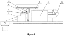
Figure 1 is a front view showing a lifting device for a current collector according to an embodiment of the present application located at a position where the current collector is lowered; -
Figure 2 is a top view showing the lifting device for the current collector according to the embodiment of the present application located at the position where the current collector is lowered; and -
Figure 3 is a front view showing the lifting device for the current collector according to the embodiment of the present application located at a where the current collector is raised. - A lifting device for a current collector is provided according to an embodiment of the present application, to realize -raising and lowering of the current collector.
- The technical solution according to the embodiments of the present application will be described clearly and completely as follows in conjunction with the accompany drawings in the embodiments of the present application, so that purposes, technical solutions and advantages of the present application can be more clear. It is obvious that the described embodiments are only a part of the embodiments according to the present application, rather than all of the embodiments. All the other embodiments obtained by those skilled in the art based on the embodiments in the present application without any creative work belong to the scope of protection of the present application.
- The lifting device for the current collector according to the present application includes: a
baseplate 10; a four-bar linkage mechanism 2 configured for driving the current collector to rise and fall, wherein a frame of the four-bar linkage mechanism 2 is arranged at thebaseplate 10; afirst driving member 3 configured for driving a crank of the four-bar linkage mechanism 2 to rotate in a direction for lowering the current collector; a first elastic member 1 having an elastic force for driving the crank to rotate in a direction for raising the current collector, wherein the first elastic member 1 has one end arranged at thebaseplate 10 and another end connected to the crank; a position-limiting member configured for limiting the four-bar linkage mechanism 10 to a position where the current collector is lowered; a secondelastic member 5 having an elastic force for locking the four-bar linkage mechanism 2 in the position-limiting member, wherein one end of the secondelastic member 5 is fixed, and another end of the secondelastic member 5 is connected to the position-limiting member; and asecond driving member 4 configured for driving the position-limiting member to release the four-bar linkage mechanism 2. - In a case that the current collector is required to be lowered, the crank of the four-
bar linkage mechanism 2 is driven by thefirst driving member 3 to rotate in the direction for lowering the current collector (that is, a counterclockwise direction inFigure 3 ), and the first elastic member 1 is deformed by force; when the crank is rotated to the position where the current collector is lowered, the four-bar linkage mechanism 2 is locked in the position-limiting member, and is held at a locked position by the elastic force of the secondelastic member 5, as shown inFigures 1 and2 , thereby realizing lowering of the current collector. In a case that the current collector is required to be raised, the driving force of thefirst driving member 3 is released, and the elastic force of the secondelastic member 5 is overcome by thesecond driving member 4, so as to drive the position-limiting member to release the four-bar linkage mechanism 2, thus, under the elastic restoring force of the first elastic member 1, the crank is rotated back to the position where the current collector is raised, back to a state shown inFigure 3 , thereby realizing raising of the current collector, and at this time, the driving force of thesecond driving member 4 is released, and the position-limiting member automatically returns to the position under the force of the secondelastic member 5. - In summary, according to the present application, the raising and lowering of the four-
bar linkage mechanism 2 is achieved by cooperation of thefirst driving member 3, thesecond driving member 4, the first elastic member 1, the secondelastic member 5 and the position-limiting member, thereby realizing raising and lowering of the current collector, and meeting the requirements of raising and lowering for electrical equipment. - In a specific embodiment of the present application, a rotating shaft of the crank is fixedly connected to a
twistable protrusion 21, and thefirst driving member 3 has a first telescopic driving shaft configured for driving thetwistable protrusion 21 to twist in the direction for lowering the current collector. According to the present application, thetwistable protrusion 21 is driven to twist by linear motion of the first telescopic driving shaft, thereby achieving counterclockwise rotation of the crank. Since a force arm of thetwistable protrusion 21 is long, a driving force required to be applied is reduced. Of course, thefirst driving member 3 can also employ other structures, such as a motor, and the crank can be directly driven to rotate by a rotating shaft of the motor. - Further, the
first driving member 3 is a lowering cylinder. According to the present application, thetwistable protrusion 21 is driven to twist by the cylinder, which has a simple structure and is convenient for installation. Alternatively, thefirst driving member 3 may also be an electric push bar. - Preferably, the first elastic member 1 is a first spring, and an axis of the first spring is parallel to an axis of the first telescopic driving shaft. The spring has a large elastic force, which ensures good stability of the raising. Of course, the first elastic member 1 may also be a torsion spring sleeved on the rotating shaft of the crank.
- In the lifting device for the current collector provided in the above embodiment, the rotating shaft of the crank is fixedly connected to a driven
twistable protrusion 22, and the first spring is connected to the driventwistable protrusion 22. As shown inFigure 1 , in a case that a driving shaft of the lowering cylinder is extended, thetwistable protrusion 21 is pushed to move rightward, and the driventwistable protrusion 22 is also driven to move rightward, thereby the first spring is elongated; in a case that the driving shaft of the lowering cylinder is retracted, the driventwistable protrusion 22 together with thetwistable protrusion 21 are driven to return by a retracting force of the first spring. According to the present application, the first spring and the lowering cylinder are connected to the driventwistable protrusion 22 and thetwistable protrusion 21, respectively, to facilitate the arrangement of the structure. Of course, the above driventwistable protrusion 22 may also not be provided according to the present application, in a case that thetwistable protrusion 21 is lengthened in an axial direction thereof, to allow the first spring to be directly connected to thetwistable protrusion 21, an effect that the first spring is directly linked with thetwistable protrusion 21 can also be achieved. - In order to facilitate locking of the four-
bar linkage mechanism 2, a connecting bar of the four-bar linkage mechanism 2 is provided with apositioning shaft 11, and the position-limiting member is able to lock thepositioning shaft 11. According to the present application, the connecting bar at a top portion is locked by a manner of locking thepositioning shaft 11 through the position-limiting member, thereby achieving locking the four-bar linkage mechanism 2, and obtaining better locking strength. Thepositioning shaft 11 may also be arranged at a link of the four-bar linkage mechanism 2 connected to the frame. The four-bar linkage mechanism 2 may not be provided with thepositioning shaft 11, instead, the four-bar linkage mechanism 2 may be provided with a positioning protrusion or a positioning locking plate. - Further, the position-limiting member is a
locking hook 6, a bottom end of thelocking hook 6 is hinged to thebaseplate 10, and a top end of thelocking hook 6 is able to hook thepositioning shaft 11. In this embodiment, under an action of the second elastic member, thepositioning shaft 11 is locked by the lockinghook 6, and thelocking hook 6 is driven by thesecond driving member 4 to rotate around a hinge point at the bottom end, thereby achieving the release of thepositioning shaft 11, and the structure is simple. Of course, the position-limiting member may also be a clamping plate arranged in a horizontal direction, and the clamping plate can be tightened downward in a vertical direction by the elastic force of the second elastic member, thereby achieving a same effect of locking the positioning shaft. - The second
elastic member 5 is a second spring, and the second spring is connected to a middle portion of thelocking hook 6. The spring has a large elastic force, which ensures good locking strength. Of course, the secondelastic member 5 may also be a leaf spring or a torsion spring sleeved on an articulated shaft at the bottom end of thelocking hook 6. - The
second driving member 4 has a second telescopic driving shaft configured for driving thelocking hook 6 to rotate in a direction of releasing thepositioning shaft 11. According to the present application, the lockinghook 6 is driven to rotate in the direction of releasing thepositioning shaft 11, that is, a clockwise direction inFigure 3 , by linear motion of the second telescopic driving shaft, to make thelocking hook 6 release a constraint on thepositioning shaft 11. Since a force arm is long, a driving force required to be applied is reduced. Of course, thesecond driving member 4 may also employ other structures, such as a motor, and thelocking hook 6 can be directly driven to rotate by a rotating shaft of the motor. - The second driving member is an unlocking cylinder, and an end of the second spring away from the locking hook is fixed to the unlocking cylinder. According to the present application, the locking
hook 6 is driven to rotate by the cylinder, which has a simple structure and is convenient for installation. Alternatively, thesecond driving member 4 may be an electric push bar. - In order to further optimize the above technical solutions, the lifting device for the current collector further includes: an insulating
bar 7 arranged at the four-bar linkage mechanism 2, wherein the insulatingbar 7 is provided with a metal member; an insulatingbracket 9 arranged at thebaseplate 10; and aposition sensing switch 8 arranged at theinsulating bracket 9, wherein theposition sensing switch 8 is able to sense the metal member in a case that the four-bar linkage mechanism 2 is at the position where the current collector is lowered. When the current collector is lowered to a desired lowered position, the metal member on the insulatingbar 7 is close to theposition sensing switch 8, theposition sensing switch 8 is closed, and a signal is sent, thereby realizing position detection of the lowering. When the current collector is raised to a desired raised position, the metal member on the insulatingbar 7 is away from theposition sensing switch 8, theposition sensing switch 8 is disconnected, and a signal is sent, thereby realizing position detection of the raising, thus, a position state of the current collector can be automatically obtained, and a driver can accurately determine whether the current collector is raised or lowered to the corresponding desired position. Alternatively, according to the present application, the same effect of determining whether the current collector is raised or lowered to the corresponding desired position may also be realized through a sensor directly detecting the position of the current collector. - The above embodiments in this specification are described in a progressive manner. Each of the embodiments is mainly focused on describing its differences from other embodiments, and references may be made among these embodiments with respect to the same or similar portions among these embodiments.
- Based on the above description of the disclosed embodiments, those skilled in the art are capable of carrying out or using the present application. It is obvious for those skilled in the art to make many modifications to these embodiments. The general principle defined herein may be applied to other embodiments without departing from the spirit or scope of the present application. Therefore, the present application is not limited to the embodiments illustrated herein, but should be defined by the broadest scope consistent with the principle and novel features disclosed herein.
Claims (10)
- A lifting device for a current collector, comprising:a baseplate (10);a four-bar linkage mechanism (2) configured for driving the current collector to rise and fall, wherein a frame of the four-bar linkage mechanism (2) is arranged at the baseplate (10);a first driving member (3) configured for driving a crank of the four-bar linkage mechanism (2) to rotate in a direction for lowering the current collector;a first elastic member (1) having an elastic force for driving the crank to rotate in a direction for raising the current collector, wherein one end of the first elastic member (1) is arranged at the baseplate (10), and another end of the first elastic member (1) is connected to the crank;a position-limiting member configured for limiting the four-bar linkage mechanism (2) to a position where the current collector is lowered;a second elastic member (5) having an elastic force for locking the four-bar linkage mechanism (2) in the position-limiting member, wherein one end of the second elastic member (5) is fixed, and another end of the second elastic member (5) is connected to the position-limiting member; anda second driving member (4) configured for driving the position-limiting member to release the four-bar linkage mechanism (2).
- The lifting device for the current collector according to claim 1, wherein a rotating shaft of the crank is fixedly connected to a twistable protrusion (21), and the first driving member (3) has a first telescopic driving shaft configured for driving the twistable protrusion (21) to twist in the direction for lowering the current collector.
- The lifting device for the current collector according to claim 2, wherein the first driving member (3) is a lowering cylinder.
- The lifting device for the current collector according to claim 2, wherein the first elastic member (1) is a first spring, and an axis of the first spring is parallel to an axis of the first telescopic driving shaft.
- The lifting device for the current collector according to claim 4, wherein the rotating shaft of the crank is fixedly connected to a driven twistable protrusion (22), and the first spring is connected to the driven twistable protrusion (22).
- The lifting device for the current collector according to claim 1, wherein a connecting bar of the four-bar linkage mechanism (2) is provided with a positioning shaft (11), and the position-limiting member is configured to lock the positioning shaft (11).
- The lifting device for the current collector according to claim 6, wherein the position-limiting member is a locking hook (6), a bottom end of the locking hook (6) is hinged to the baseplate (10), and a top end of the locking hook (6) is allowed to hook the positioning shaft (11).
- The lifting device for the current collector according to claim 7, wherein
the second elastic member (5) is a second spring, and the second spring is connected to a middle portion of the locking hook (6); and
the second driving member (4) has a second telescopic driving shaft configured for driving the locking hook (6) to rotate in a direction of releasing the positioning shaft (11). - The lifting device for the current collector according to claim 8, wherein the second driving member (4) is an unlocking cylinder, and an end of the second spring away from the locking hook (6) is fixed to the unlocking cylinder.
- The lifting device for the current collector according to any one of claims 1 to 9, further comprising:an insulating bar (7) arranged at the four-bar linkage mechanism (2), wherein the insulating bar (7) is provided with a metal member;an insulating bracket (9) arranged at the baseplate (10); anda position sensing switch (8) arranged at the insulating bracket (9), wherein the position sensing switch (8) is allowed to sense the metal member in a case that the four-bar linkage mechanism (2) is at the position where the current collector is lowered.
Applications Claiming Priority (2)
| Application Number | Priority Date | Filing Date | Title |
|---|---|---|---|
| CN201710418667.7A CN107054098A (en) | 2017-06-06 | 2017-06-06 | A kind of pantagraph current collector lowering or hoisting gear |
| PCT/CN2017/116376 WO2018223653A1 (en) | 2017-06-06 | 2017-12-15 | Lifting device for current collector |
Publications (2)
| Publication Number | Publication Date |
|---|---|
| EP3604021A1 true EP3604021A1 (en) | 2020-02-05 |
| EP3604021A4 EP3604021A4 (en) | 2020-04-22 |
Family
ID=59615704
Family Applications (1)
| Application Number | Title | Priority Date | Filing Date |
|---|---|---|---|
| EP17912660.2A Withdrawn EP3604021A4 (en) | 2017-06-06 | 2017-12-15 | Lifting device for current collector |
Country Status (3)
| Country | Link |
|---|---|
| EP (1) | EP3604021A4 (en) |
| CN (1) | CN107054098A (en) |
| WO (1) | WO2018223653A1 (en) |
Families Citing this family (11)
| Publication number | Priority date | Publication date | Assignee | Title |
|---|---|---|---|---|
| CN107054098A (en) * | 2017-06-06 | 2017-08-18 | 中车株洲电力机车有限公司 | A kind of pantagraph current collector lowering or hoisting gear |
| CN107738582B (en) * | 2017-10-26 | 2021-02-05 | 中车株洲电力机车有限公司 | Current collector of magnetic levitation vehicle |
| CN109552054B (en) * | 2019-01-18 | 2023-12-05 | 张述成 | Magnetic levitation driving lifting bow device |
| CN114103648B (en) * | 2020-08-31 | 2023-11-14 | 比亚迪股份有限公司 | Collector shoe and vehicle with same |
| CN112060917B (en) * | 2020-09-17 | 2021-09-14 | 中车青岛四方车辆研究所有限公司 | Current collector and rail vehicle |
| CN112208339B (en) * | 2020-10-09 | 2025-07-08 | 中车株洲电力机车有限公司 | Control device and control method for current collector lifting device |
| CN112551886A (en) * | 2020-11-27 | 2021-03-26 | 泰山玻璃纤维有限公司 | Multifunctional tool for disassembling and assembling head of wire drawing machine and forced beam splitting system |
| EP4543705A2 (en) * | 2022-06-22 | 2025-04-30 | First Greater Western Limited | Current collection shoe apparatus |
| CN115320393B (en) * | 2022-08-29 | 2025-01-21 | 中车株洲电力机车有限公司 | A current collector lifting device |
| CN116398596A (en) * | 2023-04-12 | 2023-07-07 | 湖南星光速流科技有限责任公司 | Telescoping system |
| CN116620032A (en) * | 2023-05-24 | 2023-08-22 | 中车株洲电力机车有限公司 | A current receiver driving device and a rail vehicle |
Family Cites Families (20)
| Publication number | Priority date | Publication date | Assignee | Title |
|---|---|---|---|---|
| JPS5520082Y2 (en) * | 1972-03-07 | 1980-05-14 | ||
| JPS5644502U (en) * | 1979-09-17 | 1981-04-22 | ||
| JPS5892801U (en) * | 1981-12-16 | 1983-06-23 | 東洋電機製造株式会社 | pantograph |
| JPH0946806A (en) * | 1995-07-27 | 1997-02-14 | Hitachi Cable Ltd | Horizontal collector for trolley wire |
| CN101062660B (en) * | 2006-04-29 | 2011-05-11 | 上海磁浮交通工程技术研究中心 | Current acceptor for current enter and reflux |
| CN201872623U (en) * | 2010-11-24 | 2011-06-22 | 陈革 | Side current collector |
| US9393874B2 (en) * | 2012-02-22 | 2016-07-19 | Hitachi Power Solutions Co., Ltd. | Trolley-type truck |
| CN202439574U (en) * | 2012-02-24 | 2012-09-19 | 陈革 | Current collector |
| JP6027450B2 (en) * | 2013-01-25 | 2016-11-16 | 東洋電機製造株式会社 | Single arm pantograph for vehicles |
| CN204020910U (en) * | 2013-10-22 | 2014-12-17 | 北京蔚蓝天创业科技发展有限公司 | A kind of block of bow collector of electric locomotive proving installation |
| CN104015624B (en) * | 2014-06-09 | 2016-01-27 | 长沙市开福区更度应用研发设计所 | With the lateral current collector of double-four link mechanism series connection |
| CN204161133U (en) * | 2014-09-26 | 2015-02-18 | 株洲市有博数码电气有限公司 | A kind of intelligent current collecting system |
| CN104691339A (en) * | 2015-01-14 | 2015-06-10 | 南车株洲电力机车有限公司 | Energy storage type trolley bus and pantograph |
| JP6605841B2 (en) * | 2015-05-25 | 2019-11-13 | 東洋電機製造株式会社 | Single arm pantograph for railway vehicles |
| CN104859456B (en) * | 2015-06-16 | 2017-08-18 | 南车株洲电力机车有限公司 | One kind becomes track pantagraph current collector and electric vehicle |
| CN104897423A (en) * | 2015-07-02 | 2015-09-09 | 株洲高新技术产业开发区壹星科技有限公司 | Detection method and system device for characteristics of locomotive pantograph |
| US9937799B2 (en) * | 2015-10-23 | 2018-04-10 | Caterpillar Inc. | Pantograph down stop for trolley |
| CN205440002U (en) * | 2015-11-02 | 2016-08-10 | 湖南中通电气股份有限公司 | A hand is from dual -purpose pantograph for electric locomotive receives electricity |
| CN205220396U (en) * | 2015-12-04 | 2016-05-11 | 湖南中通电气股份有限公司 | Auto -lock current collector |
| CN107054098A (en) * | 2017-06-06 | 2017-08-18 | 中车株洲电力机车有限公司 | A kind of pantagraph current collector lowering or hoisting gear |
-
2017
- 2017-06-06 CN CN201710418667.7A patent/CN107054098A/en active Pending
- 2017-12-15 WO PCT/CN2017/116376 patent/WO2018223653A1/en not_active Ceased
- 2017-12-15 EP EP17912660.2A patent/EP3604021A4/en not_active Withdrawn
Also Published As
| Publication number | Publication date |
|---|---|
| WO2018223653A1 (en) | 2018-12-13 |
| EP3604021A4 (en) | 2020-04-22 |
| CN107054098A (en) | 2017-08-18 |
Similar Documents
| Publication | Publication Date | Title |
|---|---|---|
| WO2018223653A1 (en) | Lifting device for current collector | |
| US20230213986A1 (en) | Electronic device and connection module therefor | |
| CN102050393B (en) | Telescopic crane and single-cylinder plug pin mechanism | |
| CN103413710B (en) | A kind of dull and stereotyped switch | |
| CN103617919B (en) | A kind of high-end straight-wavy valve Room earthed switch | |
| CN112302424A (en) | Protection structure protection method and storage cabinet protection method | |
| CN102881486B (en) | Interlocking mechanism of medium pressure switchgear | |
| CN215893559U (en) | Rotational position detection device | |
| CN114059865B (en) | Engine cover assembly for vehicle and vehicle | |
| CN203631402U (en) | Grounding switch for high end DC valve hall | |
| CN212461495U (en) | Grounding device | |
| CN101634204B (en) | Novel electrical lock | |
| CN107237560B (en) | Auxiliary lock device for auxiliary lock door | |
| CN212359600U (en) | Connecting assembly for folding well ladder and ladder thereof | |
| CN105235530B (en) | A kind of locking bar mechanism | |
| CN213278856U (en) | Intelligent humidity relay protector for transformer box | |
| CN213546188U (en) | Three-station operating mechanism | |
| CN210067576U (en) | Flat-layer anti-falling device and parking equipment | |
| CN208352545U (en) | A kind of ground line assembly and disassembly auxiliary confirmation device | |
| CN218986508U (en) | Mechanism for preventing opening when electric turnover display is closed | |
| CN212475211U (en) | Positioning frame | |
| CN114103648B (en) | Collector shoe and vehicle with same | |
| CN223471524U (en) | A switch opening and closing mechanism | |
| JP2001029146A (en) | Stored body elevating and lowering device | |
| JP4827318B2 (en) | Temporary support device |
Legal Events
| Date | Code | Title | Description |
|---|---|---|---|
| STAA | Information on the status of an ep patent application or granted ep patent |
Free format text: STATUS: THE INTERNATIONAL PUBLICATION HAS BEEN MADE |
|
| PUAI | Public reference made under article 153(3) epc to a published international application that has entered the european phase |
Free format text: ORIGINAL CODE: 0009012 |
|
| STAA | Information on the status of an ep patent application or granted ep patent |
Free format text: STATUS: REQUEST FOR EXAMINATION WAS MADE |
|
| 17P | Request for examination filed |
Effective date: 20191023 |
|
| AK | Designated contracting states |
Kind code of ref document: A1 Designated state(s): AL AT BE BG CH CY CZ DE DK EE ES FI FR GB GR HR HU IE IS IT LI LT LU LV MC MK MT NL NO PL PT RO RS SE SI SK SM TR |
|
| AX | Request for extension of the european patent |
Extension state: BA ME |
|
| A4 | Supplementary search report drawn up and despatched |
Effective date: 20200323 |
|
| RIC1 | Information provided on ipc code assigned before grant |
Ipc: B60L 5/30 20060101AFI20200317BHEP |
|
| DAV | Request for validation of the european patent (deleted) | ||
| DAX | Request for extension of the european patent (deleted) | ||
| STAA | Information on the status of an ep patent application or granted ep patent |
Free format text: STATUS: EXAMINATION IS IN PROGRESS |
|
| 17Q | First examination report despatched |
Effective date: 20220104 |
|
| STAA | Information on the status of an ep patent application or granted ep patent |
Free format text: STATUS: THE APPLICATION IS DEEMED TO BE WITHDRAWN |
|
| 18D | Application deemed to be withdrawn |
Effective date: 20230613 |