EP3604005A1 - Windshield - Google Patents
Windshield Download PDFInfo
- Publication number
- EP3604005A1 EP3604005A1 EP18777178.7A EP18777178A EP3604005A1 EP 3604005 A1 EP3604005 A1 EP 3604005A1 EP 18777178 A EP18777178 A EP 18777178A EP 3604005 A1 EP3604005 A1 EP 3604005A1
- Authority
- EP
- European Patent Office
- Prior art keywords
- glass plate
- windshield
- interlayer
- display region
- glass
- Prior art date
- Legal status (The legal status is an assumption and is not a legal conclusion. Google has not performed a legal analysis and makes no representation as to the accuracy of the status listed.)
- Pending
Links
Images







Classifications
-
- G—PHYSICS
- G02—OPTICS
- G02B—OPTICAL ELEMENTS, SYSTEMS OR APPARATUS
- G02B27/00—Optical systems or apparatus not provided for by any of the groups G02B1/00 - G02B26/00, G02B30/00
- G02B27/01—Head-up displays
- G02B27/0101—Head-up displays characterised by optical features
-
- B—PERFORMING OPERATIONS; TRANSPORTING
- B32—LAYERED PRODUCTS
- B32B—LAYERED PRODUCTS, i.e. PRODUCTS BUILT-UP OF STRATA OF FLAT OR NON-FLAT, e.g. CELLULAR OR HONEYCOMB, FORM
- B32B17/00—Layered products essentially comprising sheet glass, or glass, slag, or like fibres
- B32B17/06—Layered products essentially comprising sheet glass, or glass, slag, or like fibres comprising glass as the main or only constituent of a layer, next to another layer of a specific material
-
- B—PERFORMING OPERATIONS; TRANSPORTING
- B32—LAYERED PRODUCTS
- B32B—LAYERED PRODUCTS, i.e. PRODUCTS BUILT-UP OF STRATA OF FLAT OR NON-FLAT, e.g. CELLULAR OR HONEYCOMB, FORM
- B32B17/00—Layered products essentially comprising sheet glass, or glass, slag, or like fibres
- B32B17/06—Layered products essentially comprising sheet glass, or glass, slag, or like fibres comprising glass as the main or only constituent of a layer, next to another layer of a specific material
- B32B17/10—Layered products essentially comprising sheet glass, or glass, slag, or like fibres comprising glass as the main or only constituent of a layer, next to another layer of a specific material of synthetic resin
- B32B17/10005—Layered products essentially comprising sheet glass, or glass, slag, or like fibres comprising glass as the main or only constituent of a layer, next to another layer of a specific material of synthetic resin laminated safety glass or glazing
- B32B17/10009—Layered products essentially comprising sheet glass, or glass, slag, or like fibres comprising glass as the main or only constituent of a layer, next to another layer of a specific material of synthetic resin laminated safety glass or glazing characterized by the number, the constitution or treatment of glass sheets
- B32B17/10036—Layered products essentially comprising sheet glass, or glass, slag, or like fibres comprising glass as the main or only constituent of a layer, next to another layer of a specific material of synthetic resin laminated safety glass or glazing characterized by the number, the constitution or treatment of glass sheets comprising two outer glass sheets
-
- B—PERFORMING OPERATIONS; TRANSPORTING
- B32—LAYERED PRODUCTS
- B32B—LAYERED PRODUCTS, i.e. PRODUCTS BUILT-UP OF STRATA OF FLAT OR NON-FLAT, e.g. CELLULAR OR HONEYCOMB, FORM
- B32B17/00—Layered products essentially comprising sheet glass, or glass, slag, or like fibres
- B32B17/06—Layered products essentially comprising sheet glass, or glass, slag, or like fibres comprising glass as the main or only constituent of a layer, next to another layer of a specific material
- B32B17/10—Layered products essentially comprising sheet glass, or glass, slag, or like fibres comprising glass as the main or only constituent of a layer, next to another layer of a specific material of synthetic resin
- B32B17/10005—Layered products essentially comprising sheet glass, or glass, slag, or like fibres comprising glass as the main or only constituent of a layer, next to another layer of a specific material of synthetic resin laminated safety glass or glazing
- B32B17/10165—Functional features of the laminated safety glass or glazing
- B32B17/10339—Specific parts of the laminated safety glass or glazing being colored or tinted
- B32B17/10348—Specific parts of the laminated safety glass or glazing being colored or tinted comprising an obscuration band
-
- B—PERFORMING OPERATIONS; TRANSPORTING
- B32—LAYERED PRODUCTS
- B32B—LAYERED PRODUCTS, i.e. PRODUCTS BUILT-UP OF STRATA OF FLAT OR NON-FLAT, e.g. CELLULAR OR HONEYCOMB, FORM
- B32B17/00—Layered products essentially comprising sheet glass, or glass, slag, or like fibres
- B32B17/06—Layered products essentially comprising sheet glass, or glass, slag, or like fibres comprising glass as the main or only constituent of a layer, next to another layer of a specific material
- B32B17/10—Layered products essentially comprising sheet glass, or glass, slag, or like fibres comprising glass as the main or only constituent of a layer, next to another layer of a specific material of synthetic resin
- B32B17/10005—Layered products essentially comprising sheet glass, or glass, slag, or like fibres comprising glass as the main or only constituent of a layer, next to another layer of a specific material of synthetic resin laminated safety glass or glazing
- B32B17/1055—Layered products essentially comprising sheet glass, or glass, slag, or like fibres comprising glass as the main or only constituent of a layer, next to another layer of a specific material of synthetic resin laminated safety glass or glazing characterized by the resin layer, i.e. interlayer
- B32B17/10559—Shape of the cross-section
- B32B17/10568—Shape of the cross-section varying in thickness
-
- B—PERFORMING OPERATIONS; TRANSPORTING
- B32—LAYERED PRODUCTS
- B32B—LAYERED PRODUCTS, i.e. PRODUCTS BUILT-UP OF STRATA OF FLAT OR NON-FLAT, e.g. CELLULAR OR HONEYCOMB, FORM
- B32B17/00—Layered products essentially comprising sheet glass, or glass, slag, or like fibres
- B32B17/06—Layered products essentially comprising sheet glass, or glass, slag, or like fibres comprising glass as the main or only constituent of a layer, next to another layer of a specific material
- B32B17/10—Layered products essentially comprising sheet glass, or glass, slag, or like fibres comprising glass as the main or only constituent of a layer, next to another layer of a specific material of synthetic resin
- B32B17/10005—Layered products essentially comprising sheet glass, or glass, slag, or like fibres comprising glass as the main or only constituent of a layer, next to another layer of a specific material of synthetic resin laminated safety glass or glazing
- B32B17/1055—Layered products essentially comprising sheet glass, or glass, slag, or like fibres comprising glass as the main or only constituent of a layer, next to another layer of a specific material of synthetic resin laminated safety glass or glazing characterized by the resin layer, i.e. interlayer
- B32B17/10761—Layered products essentially comprising sheet glass, or glass, slag, or like fibres comprising glass as the main or only constituent of a layer, next to another layer of a specific material of synthetic resin laminated safety glass or glazing characterized by the resin layer, i.e. interlayer containing vinyl acetal
-
- B—PERFORMING OPERATIONS; TRANSPORTING
- B60—VEHICLES IN GENERAL
- B60J—WINDOWS, WINDSCREENS, NON-FIXED ROOFS, DOORS, OR SIMILAR DEVICES FOR VEHICLES; REMOVABLE EXTERNAL PROTECTIVE COVERINGS SPECIALLY ADAPTED FOR VEHICLES
- B60J1/00—Windows; Windscreens; Accessories therefor
-
- B—PERFORMING OPERATIONS; TRANSPORTING
- B60—VEHICLES IN GENERAL
- B60J—WINDOWS, WINDSCREENS, NON-FIXED ROOFS, DOORS, OR SIMILAR DEVICES FOR VEHICLES; REMOVABLE EXTERNAL PROTECTIVE COVERINGS SPECIALLY ADAPTED FOR VEHICLES
- B60J1/00—Windows; Windscreens; Accessories therefor
- B60J1/02—Windows; Windscreens; Accessories therefor arranged at the vehicle front, e.g. structure of the glazing, mounting of the glazing
-
- B—PERFORMING OPERATIONS; TRANSPORTING
- B60—VEHICLES IN GENERAL
- B60K—ARRANGEMENT OR MOUNTING OF PROPULSION UNITS OR OF TRANSMISSIONS IN VEHICLES; ARRANGEMENT OR MOUNTING OF PLURAL DIVERSE PRIME-MOVERS IN VEHICLES; AUXILIARY DRIVES FOR VEHICLES; INSTRUMENTATION OR DASHBOARDS FOR VEHICLES; ARRANGEMENTS IN CONNECTION WITH COOLING, AIR INTAKE, GAS EXHAUST OR FUEL SUPPLY OF PROPULSION UNITS IN VEHICLES
- B60K35/00—Instruments specially adapted for vehicles; Arrangement of instruments in or on vehicles
-
- B—PERFORMING OPERATIONS; TRANSPORTING
- B60—VEHICLES IN GENERAL
- B60K—ARRANGEMENT OR MOUNTING OF PROPULSION UNITS OR OF TRANSMISSIONS IN VEHICLES; ARRANGEMENT OR MOUNTING OF PLURAL DIVERSE PRIME-MOVERS IN VEHICLES; AUXILIARY DRIVES FOR VEHICLES; INSTRUMENTATION OR DASHBOARDS FOR VEHICLES; ARRANGEMENTS IN CONNECTION WITH COOLING, AIR INTAKE, GAS EXHAUST OR FUEL SUPPLY OF PROPULSION UNITS IN VEHICLES
- B60K35/00—Instruments specially adapted for vehicles; Arrangement of instruments in or on vehicles
- B60K35/20—Output arrangements, i.e. from vehicle to user, associated with vehicle functions or specially adapted therefor
- B60K35/21—Output arrangements, i.e. from vehicle to user, associated with vehicle functions or specially adapted therefor using visual output, e.g. blinking lights or matrix displays
- B60K35/23—Head-up displays [HUD]
-
- B—PERFORMING OPERATIONS; TRANSPORTING
- B60—VEHICLES IN GENERAL
- B60K—ARRANGEMENT OR MOUNTING OF PROPULSION UNITS OR OF TRANSMISSIONS IN VEHICLES; ARRANGEMENT OR MOUNTING OF PLURAL DIVERSE PRIME-MOVERS IN VEHICLES; AUXILIARY DRIVES FOR VEHICLES; INSTRUMENTATION OR DASHBOARDS FOR VEHICLES; ARRANGEMENTS IN CONNECTION WITH COOLING, AIR INTAKE, GAS EXHAUST OR FUEL SUPPLY OF PROPULSION UNITS IN VEHICLES
- B60K35/00—Instruments specially adapted for vehicles; Arrangement of instruments in or on vehicles
- B60K35/60—Instruments characterised by their location or relative disposition in or on vehicles
-
- C—CHEMISTRY; METALLURGY
- C03—GLASS; MINERAL OR SLAG WOOL
- C03C—CHEMICAL COMPOSITION OF GLASSES, GLAZES OR VITREOUS ENAMELS; SURFACE TREATMENT OF GLASS; SURFACE TREATMENT OF FIBRES OR FILAMENTS MADE FROM GLASS, MINERALS OR SLAGS; JOINING GLASS TO GLASS OR OTHER MATERIALS
- C03C27/00—Joining pieces of glass to pieces of other inorganic material; Joining glass to glass other than by fusing
- C03C27/06—Joining glass to glass by processes other than fusing
-
- G—PHYSICS
- G02—OPTICS
- G02B—OPTICAL ELEMENTS, SYSTEMS OR APPARATUS
- G02B27/00—Optical systems or apparatus not provided for by any of the groups G02B1/00 - G02B26/00, G02B30/00
- G02B27/01—Head-up displays
-
- B—PERFORMING OPERATIONS; TRANSPORTING
- B32—LAYERED PRODUCTS
- B32B—LAYERED PRODUCTS, i.e. PRODUCTS BUILT-UP OF STRATA OF FLAT OR NON-FLAT, e.g. CELLULAR OR HONEYCOMB, FORM
- B32B2250/00—Layers arrangement
- B32B2250/03—3 layers
-
- B—PERFORMING OPERATIONS; TRANSPORTING
- B32—LAYERED PRODUCTS
- B32B—LAYERED PRODUCTS, i.e. PRODUCTS BUILT-UP OF STRATA OF FLAT OR NON-FLAT, e.g. CELLULAR OR HONEYCOMB, FORM
- B32B2307/00—Properties of the layers or laminate
- B32B2307/10—Properties of the layers or laminate having particular acoustical properties
- B32B2307/102—Insulating
Definitions
- the present invention relates to a windshield of an automobile.
- Head-up display devices that project information such as the vehicle speed by emitting light toward a windshield of a vehicle have been proposed. If such a head-up display device is used, the driver can check the vehicle speed by looking at information projected onto the windshield instead of looking at a meter such as a speed meter within the vehicle, and accordingly need not largely deviate their eyes from the forward direction during driving. Therefore, the use of the head-up display device is advantageous in that safety during driving can be improved.
- Patent Literature 1 proposes constituting a windshield with an outer glass plate, an inner glass plate, and a resin interlayer sandwiched between these glass plates, and forming the interlayer so as to have a wedge-shaped cross section so that the entire windshield has a wedge-shaped cross section. As a result, two images overlap and generation of a double image can be prevented.
- Patent Literature 1 JP 2007-223883A
- the inventors of the present invention confirmed through studies that, if the display region is enlarged, a double image is still generated even if a wedge-shaped interlayer as described above is used.
- the present invention was made to solve this problem, and the object thereof is to provide a windshield that can prevent generation of a double image even if a display region onto which information is projected by a head-up display device is enlarged.
- the inventors of the present invention carried out intensive studies to solve the above problem. As a result, it was found that generation of a double image can be prevented with the following invention.
- a windshield that has a display region onto which information is projected using light emitted from a head-up display device, the windshield including:
- the windshield according to Aspect 4 wherein the outer glass plate and the inner glass plate have irregularities of 0.1 ⁇ m/8 mm or more in a direction perpendicular to the flow direction of glass.
- the inner glass plate has a plurality of regions that differ from each other in radius of curvature in a horizontal direction, and the display region is formed in a region other than a region that has the largest radius of curvature out of the plurality of regions.
- a method for manufacturing a windshield that has a display region onto which information is projected using light emitted from a head-up display device including steps of:
- the following describes one embodiment of a windshield according to the present invention with reference to the drawings.
- the windshield according to this embodiment has a display region onto which information is projected using light that is emitted from a head-up display device.
- FIG. 1 is a cross-sectional view of the windshield according to this embodiment and FIG. 2 is a plan view of FIG. 1 .
- the windshield according to this embodiment includes a laminated glass 1 that includes an outer glass plate 11, an inner glass plate 12, and an interlayer 13 that is arranged between these glass plates 11 and 12.
- a mask layer 2 is layered on the laminated glass 1. The following describes respective members.
- the outer glass plate 11 and the inner glass plate 12 will be described.
- Known glass plates can be used as the outer glass plate 11 and the inner glass plate 12, and these glass plates can be made of heat-ray absorbing glass, regular clear glass, green glass, or UV green glass.
- the glass plates 11 and 12 need to realize visible light transmittance that conforms to the safety standards of the country in which the automobile is to be used. For example, adjustments can be made so that the outer glass plate 11 ensures a required solar absorptance and the inner glass plate 12 provides visible light transmittance that meets safety standards.
- the following shows an example of clear glass, an example of heat-ray absorbing glass, and an example of soda lime-based glass.
- composition of heat-ray absorbing glass a composition obtained, which is based on the composition of clear glass, by setting the ratio of the total iron oxide (T-Fe 2 O 3 ) in terms of Fe 2 O 3 to 0.4 to 1.3 mass%, the ratio of CeO 2 to 0 to 2 mass%, and the ratio of TiO 2 to 0 to 0.5 mass%, and reducing the components (mainly SiO 2 and Al 2 O 3 ) forming the framework of glass by an amount corresponding to the increases in T-Fe 2 O 3 , CeO 2 , and TiO 2 can be used, for example.
- the total thickness of the outer glass plate 11 and the inner glass plate 12 is preferably set to 2.4 to 5.0 mm, more preferably 2.6 to 4.6 mm, and even more preferably 2.7 to 3.2 mm, from the viewpoint of weight reduction.
- the thicknesses of these glass plates can be determined as described below, for example. Note that the thicknesses of the glass plates can be measured using a micrometer.
- the outer glass plate 11 Durability against external damage and impact resistance are mainly required for the outer glass plate 11.
- the laminated glass is used as a windshield of an automobile, impact resistance against flying objects such as small stones is required.
- the weight increases as the thickness increases, which is not preferable.
- the thickness of the outer glass plate 11 is preferably 1.8 to 2.3 mm, and more preferably 1.9 to 2.1 mm. It is possible to determine the thickness to employ according to the use of the glass.
- the thickness of the inner glass plate 12 can be made equal to the thickness of the outer glass plate 11, but in order to reduce the weight of the laminated glass, for example, the thickness can be made smaller than that of the outer glass plate 11. Specifically, when the strength of the glass is taken into consideration, the thickness is preferably 0.6 to 2.3 mm, more preferably 0.8 to 2.0 mm, and even more preferably 1.0 to 1.4 mm. The thickness is yet more preferably 0.8 to 1.3 mm. For the inner glass plate 12 as well, it is possible to determine the thickness to employ according to the use of the glass.
- the outer glass plate 11 and the inner glass plate 12 according to this embodiment have curved shapes . It is supposed that, if a laminated glass has a curved shape, the larger the depth of bend is, the lower the sound insulation performance is.
- the depth of bend is an amount indicating the bend of a laminated glass. For example, when a straight line connecting the center of an upper side and the center of a lower side of a laminated glass is set, the greatest distance between this straight line and the laminated glass is defined as the depth of bend.
- the measurement is performed at two positions : an upper position and a lower position on a center line extending vertically at the center of the laminated glass in the left-right direction.
- a thickness gauge such as SM-112 manufactured by TECLOCK Corporation can be used, for example.
- the laminated glass is arranged such that its curved surface is placed on a flat surface, and an end portion of the laminated glass is sandwiched and measured with the above-described thickness gauge.
- the interlayer 13 is constituted by at least one layer, and can be constituted by three layers, namely a soft core layer 131 and outer layers 132 that are harder than the core layer 131 and between which the core layer 131 is sandwiched as shown in FIG. 3 , for example.
- the interlayer is not limited to this configuration, and may be constituted by a plurality of layers including the core layer 131 and at least one outer layer 132 that is arranged on the outer glass plate 11 side.
- the interlayer 13 may be constituted by two layers, namely the core layer 131 and one outer layer 132 arranged on the outer glass plate 11 side.
- the interlayer 13 may be configured by arranging an even number of outer layers 132 on each side of the core layer 131 so that the core layer 131 is located at the center.
- the interlayer 13 may be configured by arranging an odd number of outer layers 132 on one side of the core layer 131 and arranging an even number of outer layers 132 on the other side so that the core layer 131 is sandwiched therebetween. It should be noted that if only one outer layer 132 is provided, the outer layer 132 is provided on the outer glass plate 11 side as described above, which is for the purpose of enhancing the breakage resistance performance with respect to an external force from the outside of a vehicle or a building. Moreover, when the number of outer layers 132 is increased, the sound insulation performance is improved.
- the outer layers 132 can be made of a polyvinyl butyral resin (PVB), for example. Polyvinyl butyral resin has excellent adhesiveness to the glass plates and penetration resistance and is thus preferable.
- the core layer 131 can be made of, for example, an ethylene vinyl acetate resin (EVA) or a polyvinyl acetal resin, which is softer than the polyvinyl butyral resin included in the outer layers.
- EVA ethylene vinyl acetate resin
- a polyvinyl acetal resin which is softer than the polyvinyl butyral resin included in the outer layers.
- the hardness of a polyvinyl acetal resin can be controlled by adjusting (a) the degree of polymerization of a polyvinyl alcohol, which is the starting material, (b) the degree of acetalization, (c) the type of plasticizer, (d) the ratio of the plasticizer to be added, and the like. Accordingly, a hard polyvinyl butyral resin that is used for the outer layers 132 and a soft polyvinyl butyral resin that is used for the core layer 131 can be produced using the same polyvinyl butyral resin by appropriately adjusting at least one condition selected from the aforementioned conditions.
- the hardness of a polyvinyl acetal resin can also be controlled based on the type of aldehyde that is used for acetalization and whether co-acetalization using a plurality of types of aldehydes or pure acetalization using a single type of aldehyde is performed. Although not necessarily applicable to every case, the larger the number of carbon atoms of the aldehyde that is used to obtain a polyvinyl acetal resin is, the softer the resulting polyvinyl acetal resin tends to be.
- the outer layers 132 are made of a polyvinyl butyral resin
- a polyvinyl acetal resin that is obtained by acetalizing an aldehyde having 5 or more carbon atoms (e.g., n-hexyl aldehyde, 2-ethylbutyl aldehyde, n-heptyl aldehyde, or n-octyl aldehyde) with polyvinyl alcohol can be used for the core layer 131.
- an aldehyde having 5 or more carbon atoms e.g., n-hexyl aldehyde, 2-ethylbutyl aldehyde, n-heptyl aldehyde, or n-octyl aldehyde
- the total thickness of the interlayer 13 is not particularly specified, but is preferably 0.3 to 6.0 mm, more preferably 0.5 to 4.0 mm, and particularly preferably 0.6 to 2.0 mm.
- the thickness of the core layer 131 is preferably 0.1 to 2.0 mm, and more preferably 0.1 to 0.6 mm.
- the thickness of each outer layer 132 is preferably 0.1 to 2.0 mm, and more preferably 0.1 to 1.0 mm. It is also possible to fix the total thickness of the interlayer 13 while being able to adjust the thickness of the core layer 131. It should be noted that, if the interlayer 13 has a wedge shape, the layer thickness of the interlayer 13 refers to the thickness of a portion that has the smallest thickness. For example, if the windshield is attached to an automobile, the layer thickness of the interlayer refers to the thickness of the lowest portion of the interlayer.
- the thicknesses of the core layer 131 and the outer layer 132 can be measured as described below, for example. First, a cross section of the laminated glass is enlarged by a factor of 175 and displayed using a microscope (e.g., VH-5500 manufactured by Keyence Corporation). Then, the thicknesses of the core layer 131 and the outer layer 132 are visually identified and measured. At this time, in order to eliminate variations seen in visual identification, measurement is performed five times, and an average value is taken as the thickness of the core layer 131 or the outer layer 132.
- a microscope e.g., VH-5500 manufactured by Keyence Corporation
- the interlayer 13 has a wedge-shaped cross section and the thickness of the interlayer increases upward.
- the total thickness of the interlayer 13 and the thicknesses of the core layer 131 and the outer layer 132 are measured in a portion with the smallest thicknesses, that is, the lowest side portion of the laminated glass. If the interlayer 13 is constituted by three layers as described above, it is sufficient that at least one of the core layer 131 and the pair of outer layers 132 has a wedge-shaped cross section.
- the total thickness of the interlayer 13 is not particularly specified, but is preferably 0.3 to 6.0 mm, more preferably 0.5 to 4.0 mm, and particularly preferably 0.6 to 2.0 mm.
- the thickness of the core layer 131 is preferably 0.1 to 2.0 mm, and more preferably 0.1 to 0.6 mm.
- the thickness of each outer layer 132 is preferably larger than the thickness of the core layer 131, specifically, preferably 0.1 to 2.0 mm, and more preferably 0.1 to 1.0 mm. It is also possible to fix the total thickness of the interlayer 13 while being able to adjust the thickness of the core layer 131.
- the thicknesses of the core layer 131 and the outer layer 132 can be measured as described below, for example.
- a cross section of the laminated glass is enlarged by a factor of 175 and displayed using a microscope (e.g., VH-5500 manufactured by Keyence Corporation).
- the thicknesses of the core layer 131 and the outer layer 132 are visually identified and measured.
- the measurement is performed five times, and an average value is taken as the thickness of the core layer 131 or the outer layer 132.
- a photograph of the laminated glass is taken in an enlarged scale, and, in this photograph, the core layer and the outer layers 132 are identified and their thicknesses are measured.
- the method for manufacturing the interlayer 13 examples thereof include a method in which a resin component, such as the above-described polyvinyl acetal resin, a plasticizer, and other additives, if necessary, are mixed and uniformly kneaded, and then the layers are collectively extruded, and a method in which two or more resin films that are produced using this method are laminated using a pressing process, a lamination process, or the like.
- a resin component such as the above-described polyvinyl acetal resin, a plasticizer, and other additives, if necessary, are mixed and uniformly kneaded, and then the layers are collectively extruded
- two or more resin films that are produced using this method are laminated using a pressing process, a lamination process, or the like.
- each of the resin films before laminating may have a single-layer structure or a multilayer structure.
- the interlayer 13 may be constituted by a single layer rather than the plurality of layers as described above.
- the mask layer 2 is layered on the periphery of the laminated glass using ceramic of a dark color such as black.
- the mask layer 2 blocks the view from the inside or the outside of the vehicle, and is layered along four sides of the laminated glass.
- the mask layer 2 can be provided only on an inner surface of the outer glass plate 11 or an inner surface of the inner glass plate 12, or can be provided on both the inner surface of the outer glass plate 11 and the inner surface of the inner glass plate 12.
- the mask layer can have the following composition, for example.
- Table 1 First and second colored ceramic paste Pigment *1 mass% 20 Resin (cellulose resin) mass% 10 Organic solvent (pine oil) mass% 10 Glass binder *2 mass% 65 Viscosity dPs 150 *1
- Main components copper oxide, chromium oxide, iron oxide, and manganese oxide
- Main components bismuth borosilicate, zinc borosilicate
- the ceramic layer can be formed using a screen printing process
- the layer can alternatively be produced by transferring a transfer film for firing to the glass plate and firing it.
- screen printing is employed, the ceramic layer can be formed under the conditions that a polyester screen of 355 mesh is used, the coating thickness is 20 ⁇ m, the tension is 20 Nm, the squeegee hardness is 80 degrees, the attachment angle is 75°, and the printing speed is 300 mm/s, and performing drying in a drying furnace at 150°C for 10 minutes, for example.
- the mask layer 2 can be formed by attaching a blocking film that is made of a dark colored resin, instead of laminating ceramic.
- the head-up display device projects information such as the vehicle speed onto the windshield.
- information such as the vehicle speed onto the windshield.
- a HUD device projects information such as the vehicle speed onto the windshield.
- a double image will be generated by light projected onto the windshield. That is, an image that is seen as a result of reflection off an inner surface of the windshield is seen separately from an image that is seen as a result of reflection off an outer surface of the windshield, and therefore an image is duplicated.
- the wedge angle ⁇ of the windshield 1 in this case can be set to 0.01 to 0.04° (0.2 to 0.7 mrad), for example, although the wedge angle is set depending on the installation angle of the windshield 1.
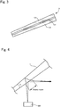
- FIG. 5 is a side view of furnaces through which the mold passes.
- a mold 800 includes a mold main body having the shape of a frame that mostly matches the external forms of the glass plates 11 and 12. Since this mold main body 810 has the shape of a frame, there is an interior space that vertically penetrates the inner side of the mold main body. Peripheral portions of the glass plates 11 and 12 each having the shape of a flat plate are placed on an upper surface of the mold main body 810. Accordingly, heat is applied to the glass plates 11 and 12 via the interior space by a heater (not shown) that is arranged below the glass plates.
- a heater not shown
- a shield plate for shielding the glass plates from heat is arranged on an inner periphery of the mold main body 810 to enable adjustment of heat applied to the glass plates 11 and 12.
- the heater can be arranged above the mold 800 as well as below the mold.
- the outer glass plate 11 and the inner glass plate 12 are superimposed and passed through a heating furnace 802 in a state of being supported by the above-described mold 800 as shown in FIG. 5 .
- a heating furnace 802 in a state of being supported by the above-described mold 800 as shown in FIG. 5 .
- the glass plates 11 and 12 are heated to around the softening point in the heating furnace 802, portions of the glass plates inward of peripheral portions curve downward under their own weight and thus the glass plates are molded into a curved shape.
- the glass plates 11 and 12 are conveyed from the heating furnace 802 to an annealing furnace 803 to be subjected to annealing treatment. Thereafter, the glass plates 11 and 12 are conveyed out of the annealing furnace 803 and cooled.
- the interlayer 13 is sandwiched between the outer glass plate 11 and the inner glass plate 12.
- the resultant laminate including the glass plates 11 and 12 and the interlayer 13 is placed into a rubber bag and preliminarily bonded together at about 70 to 110°C under vacuum suction.
- Preliminary bonding can be performed using a method other than this method, for example, the following method.
- the above-described laminate is heated at 45 to 65°C in an oven. Subsequently, this laminate is pressed by a roller at 0.45 to 0.55 MPa. Then, this laminate is again heated at 80 to 105°C in an oven and thereafter again pressed by a roller at 0.45 to 0.55 MPa.
- preliminary bonding is finished.
- the preliminarily bonded laminate is permanently bonded using an autoclave at a pressure of 8 to 15 atmospheres and at 100 to 150°C, for example.
- permanent bonding can be performed under the conditions of a pressure of 14 atmospheres and 135°C, for example.
- the interlayer 13 is bonded to the glass plates 11 and 12, and the windshield according to this embodiment is obtained. It should be noted that a curved windshield can be manufactured using a method other than this method, for example, pressing.
- the inventors of the present invention found that generation of a double image is noticeable if the display region has a large size, such as 150 mm or more in the up-down direction and 150 mm or more in the horizontal direction, or 200 mm or more in the up-down direction and 200 mm or more in the horizontal direction, for example. Therefore, the inventors of the present invention came to the following measures for suppressing generation of a double image in such a large display region.
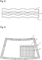
- a display region 15 is a rectangular region on the windshield that is defined by lines that pass through both ends of information (characters, a figure, or the like), which is displayed by the HUD device, in the up-down direction and lines that pass through both ends of the information in the horizontal direction.
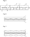
- irregularities may be formed in a surface of the windshield 1.
- the glass plates 11 and 12 in the example shown in FIG. 7 are bonded such that protruding portions of irregularities are located opposite to each other, but the glass plates 11 and 12 may be bonded such that a protruding portion and a recessed portion of irregularities are located opposite to each other as shown in FIG. 8 .
- lattice points that are arranged at a pitch of no greater than 20 mm are defined in the display region 15. Although the number of lattice points depends on the size of the display region, the maximum number of lattice points that can be set in the defined display region is set.
- wedge angles at the lattice points are determined using an interferometer with 240 ⁇ 240 pixels or more. It was found that generation of a double image in the display region 15 is suppressed if the difference between the largest value and the smallest value of the thus obtained wedge angles at the lattice points is no greater than 0.32 mrad. If the display region 15 is large and measurement cannot be performed in one measurement using the interferometer, measurement is performed a plurality of times (eight times in the illustrated example) as shown in FIG. 10 .
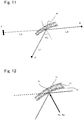
- FIG. 11 is a diagram schematically showing the position of a virtual image generated by the HUD device. If a ray of light that is emitted from a pattern P, which is a light source, is reflected off an interior side surface of the laminated glass 1 and reaches an eye E of an observer, the reflection point and the incident angle ⁇ y of the ray of light can be defined. A virtual image of the pattern P appears on an extension of a line that connects the eye E and the reflection point (incident point) R. At this time, the distance L3 between the reflection point R and the virtual image Z is determined by the distance L1 between the pattern P and the reflection point R, the distance L2 between the reflection point R and the eye E, and the lens effect of the reflection surface of the windshield.
- FIG. 12 is an enlarged view of a portion of the laminated glass.
- the laminated glass 1 is constituted by three layers, namely the outer glass plate 11, the interlayer 13, and the inner glass plate 12, and the thicknesses of the glass plates 11 and 12 are constant, but the interlayer 13 has a wedge angle.
- Surfaces of the glass plates 11 and 12 are toric surfaces with respect to the reflection point R, and the radius of curvature in the sheet face of FIG. 12 is defined as Ry while the radius of curvature in a direction perpendicular to the sheet face of FIG. 12 is defined as Rx. All glass surfaces are assumed to be the same curved surfaces.
- FIG. 13 is a diagram showing a path of light that is reflected off a vehicle exterior side surface (hereinafter referred to as a vehicle exterior surface) of the laminated glass 1 and a path of light that is reflected off a vehicle interior side surface (hereinafter referred to as a vehicle interior surface) of the laminated glass.
- the reflected light from the vehicle exterior surface and the reflected light from the vehicle interior surface have different paths from each other, and accordingly differ from each other in their positions in the virtual image plane. This is the cause of generation of a double image. Therefore, conditions regarding a typical windshield and a typical HUD device were set and the relationship between the wedge angle and the size of a double image was calculated. The calculation was performed using ray tracking software OSLO Premium Edition Rev. 6.3.0 manufactured by Lambda Research Corporation in the U.S.
- the thicknesses of the glass plates 11 and 12 constituting the laminated glass were each set to 2.0 mm and the refractive index of the glass plates was set to 1.52.
- the thickness of the interlayer 13 at the reflection point R was set to 0.8 mm and the refractive index of the interlayer was set to 1.48.
- the incident angle ⁇ y was set to 65°.
- the distance L1 between the pattern P and the reflection point R is 930 mm and the distance L2 between the reflection point R and the eye E is 1000 mm
- the distance L3 between the reflection point R and the virtual image Z is 2000 mm due to the lens effect of the reflection surface of the laminated glass 1.
- a wedge angle ⁇ y of the interlayer 13 takes a positive value.
- a wedge angle ⁇ x of the interlayer 13 takes a positive value.
- displacement ⁇ y takes a positive value. If, in the direction perpendicular to the sheet face of FIG. 13 , the virtual image Z1 of light reflected off the vehicle interior surface is located on the rear side of the virtual image Z2 of light reflected off the vehicle exterior surface, displacement ⁇ x takes a positive value.
- the displacement may be referred to as the size of a double image.
- FIG. 15 shows values of the size ⁇ x and ⁇ y of a double image when the wedge angle ⁇ y of the interlayer 13 was set to 0 and ⁇ x was changed. Double images ⁇ x in the left-right direction are generated in proportion to the values of ⁇ x. However, the inclination of the graph is significantly smaller compared to that in FIG. 14 . This indicates that generation of a double image ⁇ x in the left-right direction is not affected much by variation in the wedge angle ⁇ x.
- the optical resolution of the naked eye has a limit, and therefore even if the wedge angle ⁇ y slightly differs from the optimum value, a double image cannot be seen.
- the angular resolution of the naked eye is considered as 1 arc minute.
- the value of ⁇ y is in the range of 0.43 ⁇ 0.078 mrad.
- the size of a double image is such that it cannot be detected with the naked eye.
- the naked eye can exhibit optical resolution of 1 arc minute when a bright chart that has a high contrast and is used in an eye test is intensively stared.
- the optical resolution becomes a larger angle. If the substantial optical resolution when an image generated by the HUD device is seen is assumed to be 2 arc minutes, the range of allowable values of ⁇ y is 0.43 ⁇ 0.16 mrad. That is, it is sufficient that variation in wedge angle, namely the difference between the largest value and the smallest value of the wedge angle is no greater than 0.32 mrad.
- the smaller variation between wedge angles at the lattice points is, the more generation of a double image in the display region 15 can be suppressed. Therefore, generation of a double image can be suppressed if the difference between the largest value and the smallest value of wedge angles at a plurality of lattice points is no greater than 0.32 mrad.
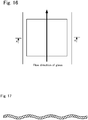
- FIG. 16 is a plan view showing the flow of glass in a float method and FIG. 17 is a cross-sectional view taken along line A-A in FIG. 16 .
- the glass plates 11 and 12 are typically formed using the float method, it is known that irregularities are likely to be formed in the float method in a direction orthogonal to the flow direction of glass as shown in FIGS. 16 and 17 . Therefore, if a laminated glass is obtained by arranging the glass plates 11 and 12 such that the flow direction of glass extends in the up-down direction, irregularities can be formed such that ridges and valleys of the irregularities extend in the up-down direction.
- the flow direction of glass need not exactly match the up-down direction of the windshield, and an angle between the flow direction of glass and the up-down direction of the windshield is preferably 10° or less, for example.
- the windshield 1 is installed in a state where the up-down direction of the windshield is largely inclined from the vertical direction.
- a double image that is formed due to irregularities in the horizontal direction i.e., variation in the wedge angle ⁇ x
- a double image that is formed due to irregularities in the up-down direction i.e., variation in the wedge angle ⁇ y
- generation of a double image in the horizontal direction is insignificant and negligible.
- a double image is likely to be generated if surfaces of the glass plates 11 and 12 have irregularities of, for example, 0.1 ⁇ m/8 mm or more in the direction perpendicular to the flow direction of glass, but generation of a double image can be suppressed if the difference between the largest value and the smallest value of wedge angles at a plurality of lattice points is no greater than 0.32 mrad as described above.
- irregularities can be measured using, for example, SURFCOM 479A manufactured by TOKYO SEIMITSU CO., LTD. as a surface roughness measurement apparatus. Further, the size of irregularities can be adjusted by changing the conveyance speed of glass in the float method, for example.
- irregularities that are formed in a surface of the laminated glass can be made small if the interlayer 13 has small irregularities before it is bonded to the glass plates 11 and 12.
- the interlayer 13 is formed from a plurality of resin layers, irregularities are formed at interfaces between the resin layers.
- Such an interlayer 13 is formed by laminating the plurality of layers by collectively extruding the layers, and irregularities can be reduced if the layers are extruded at a constant speed, for example. If the resin layers soften at high temperatures during formation, irregularities may become large. Accordingly, irregularities can also be reduced by adjusting the temperature. As described above, irregularities can be reduced by changing manufacturing conditions of the interlayer 13.
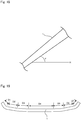
- Generation of a double image can also be suppressed by adjusting the installation angle of the windshield 1. That is, as shown in FIG. 18 , an installation angle ⁇ at which the windshield is installed in the vehicle is defined relative to a horizontal line H that extends in the horizontal direction.
- the installation angle ⁇ is an angle at the intersection between the horizontal line H and the vehicle interior surface of the laminated glass 1. If the installation angle ⁇ decreases, the incident angle and the reflection angle of light shown in FIG. 4 increase, and accordingly generation of a double image becomes noticeable. However, generation of a double image can be favorably suppressed with the windshield of the present invention even if the installation angle ⁇ is small as described above. From this standpoint, the installation angle ⁇ is preferably 60° or less, and more preferably 45° or less.
- the installation angle ⁇ is defined with respect to the vehicle interior surface for the following reason. That is, the laminated glass 1 according to this embodiment has a wedge angle, and therefore the vehicle interior surface and the vehicle exterior surface are not parallel to each other. On the other hand, a double image is generated due to inclination of the vehicle interior surface. Therefore, the installation angle ⁇ according to this embodiment is defined as the angle between the horizontal line H and the vehicle interior surface of the laminated glass.
- the windshield 1 is formed by a plurality of regions that are continuous to each other and differ from each other in radius of curvature in the horizontal direction.
- the windshield 1 has an inner surface that is formed by seven regions D1 to D7 that have different radii of curvature and are connected to each other.
- the radii of curvature of the inner surface in the regions D1 to D7 are denoted with R1 to R7, respectively.
- the inner surface is symmetrical in the left-right direction, and accordingly the radii of curvature are the same between D1 and D7, between D2 and D5, and between D3 and D6.
- the relationship between the radii of curvature is as follows.
- R 4 > R 3 R 6 >
- R 2 R 5 >
- R 1 R 7
- the display region 15 is preferably provided in a region where the radius of curvature is as large as possible. Accordingly, the display region 15 is preferably provided in any of the regions D2 to D6.
- the windshield 1 is formed so as to have a wedge-shaped cross section by forming the interlayer 13 so as to have a wedge-shaped cross section, but the laminated glass can be formed so as to have a wedge-shaped cross section by forming at least one of the outer glass plate 11 and the inner glass plate 12 so as to have a wedge-shaped cross section, for example.
- evaluation was performed using a sample with a size of 300 ⁇ 300 mm as shown in FIG. 20 that was cut out from a windshield (schematic shape: length in the up-down direction of 1060 mm ⁇ length in the left-right direction of 1560 mm) that is constituted by a laminated glass.
- a display region (length in the left-right direction of 200 mm ⁇ length in the up-down direction of 150 mm) onto which information is projected by a HUD device was provided at approximately the center of this sample.
- the thicknesses of an outer glass plate, an interlayer, and an inner glass plate at the center (position spaced from each side by 150 mm) of the sample were 2.0 mm, 0.7 mm, and 2.0 mm, respectively.
- the glass plates were obtained by subjecting flat glass plates, which were manufactured using the float method, to bending using a high-accuracy pressing process.
- the interlayer that was used had a wedge angle that was provided in advance in the up-down direction of the windshield over the entire surface. As a result of the wedge angle being provided, the thickness of the interlayer increased upward in the windshield.
- the windshield was subjected to bending, and accordingly surfaces of the sample were constituted by curved surfaces. If the left-right direction and the up-down direction in a state where the windshield is attached to an automobile are defined as a y direction and an x direction, respectively, the radius of curvature Rx in the x direction at the center of the sample was 2700 mm and the radius of curvature Ry in the y direction at the center of the sample was 9500 mm. However, the values of Rx and Ry slightly change according to positions on the sample.
- Design values of wedge angles were constant over the entire display region, and the design value of the wedge angle in the Y direction was 0.40 mrad (the thickness increases upward) and the design value of the wedge angle in the X direction was 0.
- actual wedge angles of the sample were evaluated using a device shown in FIG. 21 .
- a parallel laser beam (diameter: 102 mm, wavelength: 632.8 nm) was emitted via a reference plane from a Fizeau interferometer (model MARK GPI xps, manufactured by Zygo Corporation in the U.S.) shown in this figure toward the sample (outwardly protruding surface side) through an extremely thin light attenuation filter.
- the parallel laser beam passed through the sample was reflected off a mirror (diameter: 96 mm) and returned to the interferometer travelling the same path backward. This reflected light was allowed to interfere with reflected light from the reference plane to generate interference fringes. A CCD image of the interference fringes with 320 ⁇ 240 pixels was taken and analyzed.
- FIG. 22 shows an example of inclination of a wave front within a diameter of 96 mm illustrated by analyzing the pattern of the interference fringes. If the wave front has passed through a thick portion of the sample, the phase is delayed, and therefore the inclination of the wave front corresponds to a change in thickness of the sample, namely the wedge angle. If the wedge angle is constant, the wave front takes on a flat plane that has a constant inclination. In the example shown in FIG. 22 , the wave front does not have a perfect flat plane and has fluctuation as a result of the wedge angle changing between different positions.
- a high portion of the wave front corresponds to a thin portion of the sample, and the recorded wave front difference of 1 ⁇ m corresponds to a change in thickness of 2.083 ⁇ m.
- the measurement using the interferometer was performed eight times at different positions ((1) to (8)) on the sample. The display region was covered by the eight measurements.
- lattice points were defined in the lateral direction and 16 lattice points were defined in the lengthwise direction at intervals of 10 mm in the X and Y directions using the center of the display region as the base point.
- lattice point numbers were set in the left-right direction with a lattice point number 0 being allocated at the left end and a lattice point number 20 being allocated at the right end.
- lattice point numbers were set in the up-down direction with a lattice point number 0 being allocated at the upper end and a lattice point number 15 being allocated at the lower end. Then, wedge angles in the Y direction at respective lattice points were calculated.
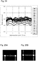
- FIG. 24 collectively shows values of the wedge angles at the lattice points, in which wedge angles in the Y direction at 21 lattice points (with lattice point numbers 0 to 21 in the left-right direction) that were arranged in a line in the lateral direction are plotted and connected by a line. That is, FIG. 24 shows 16 lines (with lattice point numbers 0 to 15 in the up-down direction) that are arranged in the up-down direction.
- the values of wedge angles fall in the range from -0.10 to +0.04 mrad relative to the design value of 0.40 mrad. This variation is sufficiently smaller than the allowable value of 0.32 mrad obtained based on the calculation example.
- FIGS. 25A and 25B show photographs of projected virtual images that were generated by the HUD device in this example.
- FIG. 25A shows displacement that occurred in the vicinity of a lattice point (No. 15 in the left-right direction and No. 9 in the up-down direction) that had the largest wedge angle in the Y direction.
- the wedge angle at this lattice point had a difference of +0.05 mrad from the reference wedge angle of 0.40 mrad, and the displacement ⁇ y in the Y direction was -0.6 mm.
- FIG. 25B shows displacement that occurred in the vicinity of a lattice point (No. 6 in the left-right direction and No. 0 in the up-down direction) that had the smallest wedge angle in the Y direction.
- the wedge angle at this lattice point had a difference of -0.09 mrad from the reference wedge angle of 0.40 mrad, and the displacement ⁇ y in the Y direction was +1.0 mm. That is, the difference between the largest value and the smallest value of wedge angles in the Y direction at all of the lattice points was 0.14 mrad.
- This result shows that, if variation in wedge angle is no greater than 0.32 mrad, generation of a double image is sufficiently suppressed as shown in these figures.
- generation of a double image in the Y direction was suppressed in this example, and the windshield of this example can be appropriately used with a HUD device that forms a large display region as described above.
- FIG. 26 collectively shows values of wedge angles at respective lattice points .
- the values of wedge angles fall in the range from -0.18 to +0.16 mrad relative to the design value of 0.40 mrad and this variation exceeds the allowable value of 0.32 mrad obtained based on the calculation example.
- FIGS. 27A and 27B show photographs of projected virtual images that were generated by the HUD device in this comparative example.
- FIG. 27A shows displacement that occurred in the vicinity of a lattice point (No. 11 in the left-right direction and No. 15 in the up-down direction) that had the largest wedge angle in the Y direction.
- the wedge angle at this lattice point had a difference of +0.15 mrad from the reference wedge angle of 0.40 mrad, and the displacement ⁇ y in the Y direction was -1.7 mm.
- FIG. 27B shows displacement that occurred in the vicinity of a lattice point (No. 17 in the left-right direction and No. 2 in the up-down direction) that had the smallest wedge angle in the Y direction.
- the wedge angle at this lattice point had a difference of -0.18 mrad from the reference wedge angle of 0.40 mrad, and the displacement ⁇ y in the Y direction was +2.0 mm. That is, the difference between the largest value and the smallest value of wedge angles in the Y direction at all of the lattice points was 0.33 mrad. This result shows that, if variation in wedge angle is greater than 0.32 mrad, a noticeable double image appears as shown in these figures. As described above, generation of a double image in the Y direction was serious in this comparative example, and the windshield of this comparative example is not suitable for use with a HUD device.
Landscapes
- Engineering & Computer Science (AREA)
- Chemical & Material Sciences (AREA)
- Mechanical Engineering (AREA)
- Physics & Mathematics (AREA)
- Transportation (AREA)
- Combustion & Propulsion (AREA)
- General Physics & Mathematics (AREA)
- Optics & Photonics (AREA)
- Life Sciences & Earth Sciences (AREA)
- Geochemistry & Mineralogy (AREA)
- Materials Engineering (AREA)
- Organic Chemistry (AREA)
- General Chemical & Material Sciences (AREA)
- Chemical Kinetics & Catalysis (AREA)
- Ceramic Engineering (AREA)
- Joining Of Glass To Other Materials (AREA)
Abstract
Description
- The present invention relates to a windshield of an automobile.
- Head-up display devices that project information such as the vehicle speed by emitting light toward a windshield of a vehicle have been proposed. If such a head-up display device is used, the driver can check the vehicle speed by looking at information projected onto the windshield instead of looking at a meter such as a speed meter within the vehicle, and accordingly need not largely deviate their eyes from the forward direction during driving. Therefore, the use of the head-up display device is advantageous in that safety during driving can be improved.
- However, there is a problem that, if the above-described head-up display device is used for a windshield that has a uniform thickness, a double image phenomenon occurs in which an image projected onto the windshield, that is, information such as the vehicle speed is duplicated due to generation of an image that is seen as a result of reflection from an inner surface of the windshield and generation of an image that is seen as a result of reflection from an outer surface of the windshield. In order to solve this problem, for example,
Patent Literature 1 proposes constituting a windshield with an outer glass plate, an inner glass plate, and a resin interlayer sandwiched between these glass plates, and forming the interlayer so as to have a wedge-shaped cross section so that the entire windshield has a wedge-shaped cross section. As a result, two images overlap and generation of a double image can be prevented. - Patent Literature 1:
JP 2007-223883A - However, recent years have seen a trend toward enlargement of a display region of information that is projected onto a windshield by a head-up display device. The inventors of the present invention confirmed through studies that, if the display region is enlarged, a double image is still generated even if a wedge-shaped interlayer as described above is used. The present invention was made to solve this problem, and the object thereof is to provide a windshield that can prevent generation of a double image even if a display region onto which information is projected by a head-up display device is enlarged.
- The inventors of the present invention carried out intensive studies to solve the above problem. As a result, it was found that generation of a double image can be prevented with the following invention.
- A windshield that has a display region onto which information is projected using light emitted from a head-up display device, the windshield including:
- an outer glass plate;
- an inner glass plate that is arranged opposite to the outer glass plate; and
- an interlayer that is arranged between the outer glass plate and the inner glass plate,
- wherein lattice points are defined at a pitch of no greater than 20 mm in the display region, and
- when wedge angles at the lattice points are measured using an interferometer with 240 × 240 pixels or more, a difference between the largest value and the smallest value of the wedge angles is no greater than 0.32 mrad.
- The windshield according to
Aspect 1, wherein the display region has a size of 150 mm or more in an up-down direction and 150 mm or more in a horizontal direction. - The windshield according to
Aspect - The windshield according to any one of
Aspects 1 to 3, wherein the outer glass plate and the inner glass plate are arranged such that a flow direction of glass in a float method extends in an up-down direction. - The windshield according to
Aspect 4, wherein the outer glass plate and the inner glass plate have irregularities of 0.1 µm/8 mm or more in a direction perpendicular to the flow direction of glass. - The windshield according to
Aspect - The windshield according to any one of
Aspects 1 to 6, wherein the windshield is installed in a vehicle at an installation angle of 60° or less relative to a horizontal direction. - The windshield according to any one of
Aspects 1 to 7, wherein the inner glass plate has a plurality of regions that differ from each other in radius of curvature in a horizontal direction, and
the display region is formed in a region other than a region that has the largest radius of curvature out of the plurality of regions. - A method for manufacturing a windshield that has a display region onto which information is projected using light emitted from a head-up display device, the method including steps of:
- preparing an outer glass plate;
- preparing an inner glass plate;
- preparing an interlayer; and
- arranging the interlayer between the outer glass plate and the inner glass plate and bonding together the outer glass plate, the inner glass plate, and the interlayer,
- wherein lattice points are defined at a pitch of no greater than 20 mm in the display region, and
- when wedge angles at the lattice points are measured using an interferometer with 240 × 240 pixels or more, a difference between the largest value and the smallest value of the wedge angles is no greater than 0.32 mrad.
- The method for manufacturing a windshield according to
Aspect 9, wherein the outer glass plate and the inner glass plate are formed using a float method, and
the outer glass plate and the inner glass plate are arranged such that a flow direction of glass in the float method extends in an up-down direction. - With the windshield and the method for manufacturing the same according to the present invention, generation of a double image can be prevented even if a display region onto which information is projected by a head-up display device is enlarged.
-
-
FIG. 1 is a cross-sectional view of one embodiment of a windshield according to the present invention. -
FIG. 2 is a plan view ofFIG. 1 . -
FIG. 3 is a cross-sectional view of an interlayer. -
FIG. 4 is a side view showing the positional relationship between a head-up display device and a windshield. -
FIG. 5 is a side view showing one example of a manufacturing method of a glass plate. -
FIG. 6 is a cross-sectional view showing one example of glass plates and an interlayer. -
FIG. 7 is a cross-sectional view showing one example of glass plates and an interlayer. -
FIG. 8 is a cross-sectional view showing one example of glass plates and an interlayer. -
FIG. 9 is a plan view of a windshield showing a display region. -
FIG. 10 is an enlarged plan view ofFIG. 9 showing one example of a method for measuring a wedge angle. -
FIG. 11 is a diagram for explaining a double image. -
FIG. 12 is a diagram for explaining a double image. -
FIG. 13 is a diagram for explaining a double image. -
FIG. 14 is a graph showing the relationship between a wedge angle in a y direction and a double image. -
FIG. 15 is a graph showing the relationship between a wedge angle in an x direction and a double image. -
FIG. 16 is a plan view showing one example of a manufacturing method of a glass plate. -
FIG. 17 is a cross-sectional view taken along line A-A inFIG. 16 . -
FIG. 18 is a cross-sectional view of a windshield. -
FIG. 19 is a cross-sectional view of a windshield. -
FIG. 20 is a plan view for explaining measurement of wedge angles according to an example and a comparative example. -
FIG. 21 is a diagram illustrating a schematic configuration of a measurement device of the wedge angle. -
FIG. 22 is a diagram showing inclination of a wave front within a diameter of 96 mm of a glass surface obtained by analyzing an interference fringe pattern. -
FIG. 23 is a diagram showing a measurement region in which lattice points are arranged. -
FIG. 24 is a graph showing wedge angles at lattice points in the example. -
FIG. 25A is a diagram showing a photograph of lattice points in the example. -
FIG. 25B is a diagram showing a photograph of lattice points in the example. -
FIG. 26 is a graph showing wedge angles at lattice points in the comparative example. -
FIG. 27A is a diagram showing a photograph of lattice points in the example. -
FIG. 27B is a diagram showing a photograph of lattice points in the example. - The following describes one embodiment of a windshield according to the present invention with reference to the drawings. The windshield according to this embodiment has a display region onto which information is projected using light that is emitted from a head-up display device.
-
FIG. 1 is a cross-sectional view of the windshield according to this embodiment andFIG. 2 is a plan view ofFIG. 1 . As shown inFIGS. 1 and 2 , the windshield according to this embodiment includes alaminated glass 1 that includes anouter glass plate 11, aninner glass plate 12, and aninterlayer 13 that is arranged between theseglass plates mask layer 2 is layered on thelaminated glass 1. The following describes respective members. - First, the
outer glass plate 11 and theinner glass plate 12 will be described. Known glass plates can be used as theouter glass plate 11 and theinner glass plate 12, and these glass plates can be made of heat-ray absorbing glass, regular clear glass, green glass, or UV green glass. However, theglass plates outer glass plate 11 ensures a required solar absorptance and theinner glass plate 12 provides visible light transmittance that meets safety standards. The following shows an example of clear glass, an example of heat-ray absorbing glass, and an example of soda lime-based glass. -
- SiO2: 70 to 73 mass%
- Al2O3: 0.6 to 2.4 mass%
- CaO: 7 to 12 mass%
- MgO: 1.0 to 4.5 mass%
- R2O: 13 to 15 mass% (R is an alkali metal)
- Total iron oxide (T-Fe2O3) in terms of Fe2O3: 0.08 to 0.14 mass%
- With regard to the composition of heat-ray absorbing glass, a composition obtained, which is based on the composition of clear glass, by setting the ratio of the total iron oxide (T-Fe2O3) in terms of Fe2O3 to 0.4 to 1.3 mass%, the ratio of CeO2 to 0 to 2 mass%, and the ratio of TiO2 to 0 to 0.5 mass%, and reducing the components (mainly SiO2 and Al2O3) forming the framework of glass by an amount corresponding to the increases in T-Fe2O3, CeO2, and TiO2 can be used, for example.
-
- SiO2: 65 to 80 mass%
- Al2O3: 0 to 5 mass%
- CaO: 5 to 15 mass%
- MgO: at least 2 mass%
- NaO: 10 to 18 mass%
- K2O: 0 to 5 mass%
- MgO + CaO: 5 to 15 mass%
- Na2O + K2O: 10 to 20 mass%
- SO3: 0.05 to 0.3 mass%
- B2O3: 0 to 5 mass%
- Total iron oxide (T-Fe2O3) in terms of Fe2O3: 0.02 to 0.03 mass%
- Although there is no particular limitation on the thickness of the laminated glass according to this embodiment, the total thickness of the
outer glass plate 11 and theinner glass plate 12 is preferably set to 2.4 to 5.0 mm, more preferably 2.6 to 4.6 mm, and even more preferably 2.7 to 3.2 mm, from the viewpoint of weight reduction. As described above, it is necessary to reduce the total thickness of theouter glass plate 11 and theinner glass plate 12 in order to reduce the weight, and therefore, although there is no particular limitation on the thicknesses of theouter glass plate 11 and theinner glass plate 12, the thicknesses of these glass plates can be determined as described below, for example. Note that the thicknesses of the glass plates can be measured using a micrometer. - Durability against external damage and impact resistance are mainly required for the
outer glass plate 11. For example, if the laminated glass is used as a windshield of an automobile, impact resistance against flying objects such as small stones is required. On the other hand, the weight increases as the thickness increases, which is not preferable. From this viewpoint, the thickness of theouter glass plate 11 is preferably 1.8 to 2.3 mm, and more preferably 1.9 to 2.1 mm. It is possible to determine the thickness to employ according to the use of the glass. - The thickness of the
inner glass plate 12 can be made equal to the thickness of theouter glass plate 11, but in order to reduce the weight of the laminated glass, for example, the thickness can be made smaller than that of theouter glass plate 11. Specifically, when the strength of the glass is taken into consideration, the thickness is preferably 0.6 to 2.3 mm, more preferably 0.8 to 2.0 mm, and even more preferably 1.0 to 1.4 mm. The thickness is yet more preferably 0.8 to 1.3 mm. For theinner glass plate 12 as well, it is possible to determine the thickness to employ according to the use of the glass. - The
outer glass plate 11 and theinner glass plate 12 according to this embodiment have curved shapes . It is supposed that, if a laminated glass has a curved shape, the larger the depth of bend is, the lower the sound insulation performance is. The depth of bend is an amount indicating the bend of a laminated glass. For example, when a straight line connecting the center of an upper side and the center of a lower side of a laminated glass is set, the greatest distance between this straight line and the laminated glass is defined as the depth of bend. - Here, one example of a method for measuring the thickness of the
laminated glass 1 will be described. First, with respect to the measurement position, the measurement is performed at two positions : an upper position and a lower position on a center line extending vertically at the center of the laminated glass in the left-right direction. Although there is no particular limitation on the measurement device, a thickness gauge such as SM-112 manufactured by TECLOCK Corporation can be used, for example. During measurement, the laminated glass is arranged such that its curved surface is placed on a flat surface, and an end portion of the laminated glass is sandwiched and measured with the above-described thickness gauge. - The
interlayer 13 is constituted by at least one layer, and can be constituted by three layers, namely asoft core layer 131 andouter layers 132 that are harder than thecore layer 131 and between which thecore layer 131 is sandwiched as shown inFIG. 3 , for example. However, the interlayer is not limited to this configuration, and may be constituted by a plurality of layers including thecore layer 131 and at least oneouter layer 132 that is arranged on theouter glass plate 11 side. For example, theinterlayer 13 may be constituted by two layers, namely thecore layer 131 and oneouter layer 132 arranged on theouter glass plate 11 side. Alternatively, theinterlayer 13 may be configured by arranging an even number ofouter layers 132 on each side of thecore layer 131 so that thecore layer 131 is located at the center. Alternatively, theinterlayer 13 may be configured by arranging an odd number ofouter layers 132 on one side of thecore layer 131 and arranging an even number ofouter layers 132 on the other side so that thecore layer 131 is sandwiched therebetween. It should be noted that if only oneouter layer 132 is provided, theouter layer 132 is provided on theouter glass plate 11 side as described above, which is for the purpose of enhancing the breakage resistance performance with respect to an external force from the outside of a vehicle or a building. Moreover, when the number ofouter layers 132 is increased, the sound insulation performance is improved. - There is no particular limitation on the hardness of the
core layer 131 as long as thecore layer 131 is softer than theouter layers 132. Although there is no particular limitation on the materials constituting thelayers outer layers 132 can be made of a polyvinyl butyral resin (PVB), for example. Polyvinyl butyral resin has excellent adhesiveness to the glass plates and penetration resistance and is thus preferable. On the other hand, thecore layer 131 can be made of, for example, an ethylene vinyl acetate resin (EVA) or a polyvinyl acetal resin, which is softer than the polyvinyl butyral resin included in the outer layers. When the soft core layer is sandwiched between the outer layers, the sound insulation performance can be significantly improved while maintaining the adhesiveness and the penetration resistance that are equivalent to those of a single-layered resin interlayer. - Generally, the hardness of a polyvinyl acetal resin can be controlled by adjusting (a) the degree of polymerization of a polyvinyl alcohol, which is the starting material, (b) the degree of acetalization, (c) the type of plasticizer, (d) the ratio of the plasticizer to be added, and the like. Accordingly, a hard polyvinyl butyral resin that is used for the
outer layers 132 and a soft polyvinyl butyral resin that is used for thecore layer 131 can be produced using the same polyvinyl butyral resin by appropriately adjusting at least one condition selected from the aforementioned conditions. Furthermore, the hardness of a polyvinyl acetal resin can also be controlled based on the type of aldehyde that is used for acetalization and whether co-acetalization using a plurality of types of aldehydes or pure acetalization using a single type of aldehyde is performed. Although not necessarily applicable to every case, the larger the number of carbon atoms of the aldehyde that is used to obtain a polyvinyl acetal resin is, the softer the resulting polyvinyl acetal resin tends to be. Accordingly, for example, if theouter layers 132 are made of a polyvinyl butyral resin, a polyvinyl acetal resin that is obtained by acetalizing an aldehyde having 5 or more carbon atoms (e.g., n-hexyl aldehyde, 2-ethylbutyl aldehyde, n-heptyl aldehyde, or n-octyl aldehyde) with polyvinyl alcohol can be used for thecore layer 131. It should be noted that there is no limitation to the above-described resins and the like as long as predetermined Young's moduli can be obtained. - The total thickness of the
interlayer 13 is not particularly specified, but is preferably 0.3 to 6.0 mm, more preferably 0.5 to 4.0 mm, and particularly preferably 0.6 to 2.0 mm. The thickness of thecore layer 131 is preferably 0.1 to 2.0 mm, and more preferably 0.1 to 0.6 mm. On the other hand, the thickness of eachouter layer 132 is preferably 0.1 to 2.0 mm, and more preferably 0.1 to 1.0 mm. It is also possible to fix the total thickness of theinterlayer 13 while being able to adjust the thickness of thecore layer 131. It should be noted that, if theinterlayer 13 has a wedge shape, the layer thickness of theinterlayer 13 refers to the thickness of a portion that has the smallest thickness. For example, if the windshield is attached to an automobile, the layer thickness of the interlayer refers to the thickness of the lowest portion of the interlayer. - The thicknesses of the
core layer 131 and theouter layer 132 can be measured as described below, for example. First, a cross section of the laminated glass is enlarged by a factor of 175 and displayed using a microscope (e.g., VH-5500 manufactured by Keyence Corporation). Then, the thicknesses of thecore layer 131 and theouter layer 132 are visually identified and measured. At this time, in order to eliminate variations seen in visual identification, measurement is performed five times, and an average value is taken as the thickness of thecore layer 131 or theouter layer 132. - The
interlayer 13 has a wedge-shaped cross section and the thickness of the interlayer increases upward. In this case, the total thickness of theinterlayer 13 and the thicknesses of thecore layer 131 and theouter layer 132 are measured in a portion with the smallest thicknesses, that is, the lowest side portion of the laminated glass. If theinterlayer 13 is constituted by three layers as described above, it is sufficient that at least one of thecore layer 131 and the pair ofouter layers 132 has a wedge-shaped cross section. - The total thickness of the
interlayer 13 is not particularly specified, but is preferably 0.3 to 6.0 mm, more preferably 0.5 to 4.0 mm, and particularly preferably 0.6 to 2.0 mm. The thickness of thecore layer 131 is preferably 0.1 to 2.0 mm, and more preferably 0.1 to 0.6 mm. On the other hand, the thickness of eachouter layer 132 is preferably larger than the thickness of thecore layer 131, specifically, preferably 0.1 to 2.0 mm, and more preferably 0.1 to 1.0 mm. It is also possible to fix the total thickness of theinterlayer 13 while being able to adjust the thickness of thecore layer 131. - The thicknesses of the
core layer 131 and theouter layer 132 can be measured as described below, for example. First, a cross section of the laminated glass is enlarged by a factor of 175 and displayed using a microscope (e.g., VH-5500 manufactured by Keyence Corporation). Then, the thicknesses of thecore layer 131 and theouter layer 132 are visually identified and measured. At this time, in order to eliminate variations seen in visual identification, the measurement is performed five times, and an average value is taken as the thickness of thecore layer 131 or theouter layer 132. For example, a photograph of the laminated glass is taken in an enlarged scale, and, in this photograph, the core layer and theouter layers 132 are identified and their thicknesses are measured. - Although there is no particular limitation on the method for manufacturing the
interlayer 13, examples thereof include a method in which a resin component, such as the above-described polyvinyl acetal resin, a plasticizer, and other additives, if necessary, are mixed and uniformly kneaded, and then the layers are collectively extruded, and a method in which two or more resin films that are produced using this method are laminated using a pressing process, a lamination process, or the like. In the method for laminating using the pressing process, the lamination process, or the like, each of the resin films before laminating may have a single-layer structure or a multilayer structure. Theinterlayer 13 may be constituted by a single layer rather than the plurality of layers as described above. - As shown in
FIG. 1 , themask layer 2 is layered on the periphery of the laminated glass using ceramic of a dark color such as black. Themask layer 2 blocks the view from the inside or the outside of the vehicle, and is layered along four sides of the laminated glass. - Various configurations can be employed for the
mask layer 2, for example, themask layer 2 can be provided only on an inner surface of theouter glass plate 11 or an inner surface of theinner glass plate 12, or can be provided on both the inner surface of theouter glass plate 11 and the inner surface of theinner glass plate 12. Although various materials can be used for themask layer 2, the mask layer can have the following composition, for example.Table 1 First and second colored ceramic paste Pigment *1 mass% 20 Resin (cellulose resin) mass% 10 Organic solvent (pine oil) mass% 10 Glass binder *2 mass% 65 Viscosity dPs 150 *1 Main components: copper oxide, chromium oxide, iron oxide, and manganese oxide
*2: Main components: bismuth borosilicate, zinc borosilicate - Although the ceramic layer can be formed using a screen printing process, the layer can alternatively be produced by transferring a transfer film for firing to the glass plate and firing it. If screen printing is employed, the ceramic layer can be formed under the conditions that a polyester screen of 355 mesh is used, the coating thickness is 20 µm, the tension is 20 Nm, the squeegee hardness is 80 degrees, the attachment angle is 75°, and the printing speed is 300 mm/s, and performing drying in a drying furnace at 150°C for 10 minutes, for example.
- Alternatively, the
mask layer 2 can be formed by attaching a blocking film that is made of a dark colored resin, instead of laminating ceramic. - Next, the head-up display device will be described. The head-up display device (also referred to as a HUD device) projects information such as the vehicle speed onto the windshield. However, it is known that, if a HUD device is used, a double image will be generated by light projected onto the windshield. That is, an image that is seen as a result of reflection off an inner surface of the windshield is seen separately from an image that is seen as a result of reflection off an outer surface of the windshield, and therefore an image is duplicated.
- In order to prevent this, at least the display region of the
windshield 1 onto which light is projected by aHUD device 500 is formed such that the thickness decreases downward as shown inFIG. 4 . As a result, light that is reflected off the inner surface of thewindshield 1 and then enters the inside of the vehicle and light that is reflected off the outer surface of the windshield and then enters the inside of the vehicle mostly match and the problem of generation of a double image is resolved. It should be noted that the wedge angle α of thewindshield 1 in this case can be set to 0.01 to 0.04° (0.2 to 0.7 mrad), for example, although the wedge angle is set depending on the installation angle of thewindshield 1. - Next, a manufacturing method of the windshield will be described. First, a manufacturing line of the glass plates will be described.
- Here, a mold will be described in detail with reference to
FIG. 5. FIG. 5 is a side view of furnaces through which the mold passes. As shown inFIG. 5 , amold 800 includes a mold main body having the shape of a frame that mostly matches the external forms of theglass plates main body 810 has the shape of a frame, there is an interior space that vertically penetrates the inner side of the mold main body. Peripheral portions of theglass plates main body 810. Accordingly, heat is applied to theglass plates glass plates main body 810 to enable adjustment of heat applied to theglass plates mold 800 as well as below the mold. - After the above-described
mask layer 2 is layered on theouter glass plate 11 and theinner glass plate 12 having the shape of a flat plate, theouter glass plate 11 and theinner glass plate 12 are superimposed and passed through aheating furnace 802 in a state of being supported by the above-describedmold 800 as shown inFIG. 5 . When theglass plates heating furnace 802, portions of the glass plates inward of peripheral portions curve downward under their own weight and thus the glass plates are molded into a curved shape. Subsequently, theglass plates heating furnace 802 to anannealing furnace 803 to be subjected to annealing treatment. Thereafter, theglass plates annealing furnace 803 and cooled. - After the
outer glass plate 11 and theinner glass plate 12 are molded as described above, theinterlayer 13 is sandwiched between theouter glass plate 11 and theinner glass plate 12. Next, the resultant laminate including theglass plates interlayer 13 is placed into a rubber bag and preliminarily bonded together at about 70 to 110°C under vacuum suction. Preliminary bonding can be performed using a method other than this method, for example, the following method. For example, the above-described laminate is heated at 45 to 65°C in an oven. Subsequently, this laminate is pressed by a roller at 0.45 to 0.55 MPa. Then, this laminate is again heated at 80 to 105°C in an oven and thereafter again pressed by a roller at 0.45 to 0.55 MPa. Thus, preliminary bonding is finished. - Next, permanent bonding is performed. The preliminarily bonded laminate is permanently bonded using an autoclave at a pressure of 8 to 15 atmospheres and at 100 to 150°C, for example. Specifically, permanent bonding can be performed under the conditions of a pressure of 14 atmospheres and 135°C, for example. Through the above-described preliminary boding and permanent bonding, the
interlayer 13 is bonded to theglass plates - In recent years, enlarging the display region of the
windshield 1 in which information is displayed by the head-updisplay device 500 has been considered. However, the inventors of the present invention found that, if the display region is enlarged, the problem of generation of a double image cannot be resolved even if thewindshield 1 is formed so as to have a wedge-shaped cross section as described above. This is because wave-shaped irregularities are formed in a surface of thewindshield 1, and it was found that, in particular, irregularities that include ridges and valleys extending in the horizontal direction affect generation of a double image. Although such irregularities do not cause problems if the display region is small, the inventors of the present invention found that generation of a double image is noticeable if the display region has a large size, such as 150 mm or more in the up-down direction and 150 mm or more in the horizontal direction, or 200 mm or more in the up-down direction and 200 mm or more in the horizontal direction, for example. Therefore, the inventors of the present invention came to the following measures for suppressing generation of a double image in such a large display region. It should be noted that adisplay region 15 is a rectangular region on the windshield that is defined by lines that pass through both ends of information (characters, a figure, or the like), which is displayed by the HUD device, in the up-down direction and lines that pass through both ends of the information in the horizontal direction. - It is thought that a double image is mainly generated in any of the following cases or a combination thereof. First, as shown in
FIG. 6 , there is a case where almost no irregularities are formed in theouter glass plate 11 and theinner glass plate 12 but irregularities are formed in surfaces of theinterlayer 13. In this case, when theglass plates interlayer 13 are permanently bonded as described above, irregularities may also be formed in theglass plates interlayer 13. - Also, as shown in
FIG. 7 , there is a case where almost no irregularities are formed in theinterlayer 13 but irregularities are formed in theglass plates windshield 1. It should be noted that, theglass plates FIG. 7 are bonded such that protruding portions of irregularities are located opposite to each other, but theglass plates FIG. 8 . - The inventors of the present invention found the following with regard to cases where irregularities are formed as described above. First, as shown in
FIG. 9 , lattice points that are arranged at a pitch of no greater than 20 mm are defined in thedisplay region 15. Although the number of lattice points depends on the size of the display region, the maximum number of lattice points that can be set in the defined display region is set. Next, wedge angles at the lattice points are determined using an interferometer with 240 × 240 pixels or more. It was found that generation of a double image in thedisplay region 15 is suppressed if the difference between the largest value and the smallest value of the thus obtained wedge angles at the lattice points is no greater than 0.32 mrad. If thedisplay region 15 is large and measurement cannot be performed in one measurement using the interferometer, measurement is performed a plurality of times (eight times in the illustrated example) as shown inFIG. 10 . - It should be noted that, according to studies carried out by the inventors of the present invention, "random variation in thickness of the interlayer" and "random irregularities formed in a glass surface at the interface between glass and air", which are main causes of variation in wedge angle, are caused by a convex lens portion or a concave lens portion that has a size of about 20 to 50 mm. Accordingly, if the density of the lattice points (measurement points) in the
display region 15 is such that the lattice points are arranged at intervals (pitch) of no greater than 20 mm, evaluation can be performed without faulty portions being overlooked. Therefore, the pitch between the lattice points is preferably no greater than 15 mm, and more preferably no greater than 10 mm. - The above finding will be examined based on a specific calculation example.
FIG. 11 is a diagram schematically showing the position of a virtual image generated by the HUD device. If a ray of light that is emitted from a pattern P, which is a light source, is reflected off an interior side surface of thelaminated glass 1 and reaches an eye E of an observer, the reflection point and the incident angle θy of the ray of light can be defined. A virtual image of the pattern P appears on an extension of a line that connects the eye E and the reflection point (incident point) R. At this time, the distance L3 between the reflection point R and the virtual image Z is determined by the distance L1 between the pattern P and the reflection point R, the distance L2 between the reflection point R and the eye E, and the lens effect of the reflection surface of the windshield. -
FIG. 12 is an enlarged view of a portion of the laminated glass. As described above, thelaminated glass 1 is constituted by three layers, namely theouter glass plate 11, theinterlayer 13, and theinner glass plate 12, and the thicknesses of theglass plates interlayer 13 has a wedge angle. Surfaces of theglass plates FIG. 12 is defined as Ry while the radius of curvature in a direction perpendicular to the sheet face ofFIG. 12 is defined as Rx. All glass surfaces are assumed to be the same curved surfaces. -
FIG. 13 is a diagram showing a path of light that is reflected off a vehicle exterior side surface (hereinafter referred to as a vehicle exterior surface) of thelaminated glass 1 and a path of light that is reflected off a vehicle interior side surface (hereinafter referred to as a vehicle interior surface) of the laminated glass. The reflected light from the vehicle exterior surface and the reflected light from the vehicle interior surface have different paths from each other, and accordingly differ from each other in their positions in the virtual image plane. This is the cause of generation of a double image. Therefore, conditions regarding a typical windshield and a typical HUD device were set and the relationship between the wedge angle and the size of a double image was calculated. The calculation was performed using ray tracking software OSLO Premium Edition Rev. 6.3.0 manufactured by Lambda Research Corporation in the U.S. - The thicknesses of the
glass plates interlayer 13 at the reflection point R was set to 0.8 mm and the refractive index of the interlayer was set to 1.48. The radii of curvature of the laminated glass 1 (toric surface) at the reflection point R were set to Rx = 4000 mm and Ry = 8000 mm. The incident angle θy was set to 65°. - If the distance L1 between the pattern P and the reflection point R is 930 mm and the distance L2 between the reflection point R and the eye E is 1000 mm, the distance L3 between the reflection point R and the virtual image Z is 2000 mm due to the lens effect of the reflection surface of the
laminated glass 1. If the thickness of theinterlayer 13 increases rightward as shown inFIG. 12 , a wedge angle φy of theinterlayer 13 takes a positive value. If, in the direction perpendicular to the sheet face ofFIG. 12 , the thickness of theinterlayer 13 increases rearward and decreases forward, a wedge angle φx of theinterlayer 13 takes a positive value. - With regard to the positional relationship between virtual images, if a virtual image Z1 of light that is reflected off the vehicle interior surface is located below a virtual image Z2 of light that is reflected off the vehicle exterior surface as shown in
FIG. 13 , displacement Δy takes a positive value. If, in the direction perpendicular to the sheet face ofFIG. 13 , the virtual image Z1 of light reflected off the vehicle interior surface is located on the rear side of the virtual image Z2 of light reflected off the vehicle exterior surface, displacement Δx takes a positive value. In the following description, the displacement may be referred to as the size of a double image. -
FIG. 14 shows values of the size Δx and Δy of a double image when the wedge angle φx of theinterlayer 13 was set to 0 and φy was changed. If φy = 0 (i.e., there is no wedge angle), a large double image is generated in which Δy = +4.8 mm, but if the wedge angle φy = +0.43 mrad, values indicating the size of a double image are approximately zero. Further, a double image Δx in the left-right direction is not generated. -
FIG. 15 shows values of the size Δx and Δy of a double image when the wedge angle φy of theinterlayer 13 was set to 0 and φx was changed. Double images Δx in the left-right direction are generated in proportion to the values of φx. However, the inclination of the graph is significantly smaller compared to that inFIG. 14 . This indicates that generation of a double image Δx in the left-right direction is not affected much by variation in the wedge angle φx. - As is clear from
FIG. 14 , the wedge angle φy = 0.43 mrad is the optimum value. However, the optical resolution of the naked eye has a limit, and therefore even if the wedge angle φy slightly differs from the optimum value, a double image cannot be seen. The angular resolution of the naked eye is considered as 1 arc minute. In the case of this calculation example, the distance between the eye E and the virtual image Z is L2 + L3 = 3000 mm, and therefore the value of Δy corresponding to an angle of 1 arc minute is 3000 × tan (1 arc minute) = 0.87 (mm) . - According to the inclination of the graph in
FIG. 14 , in order to bring the value of Δy into the range of ±0.87 mm, it is sufficient that the value of φy is in the range of 0.43 ± 0.078 mrad. In this range, the size of a double image is such that it cannot be detected with the naked eye. - Incidentally, the naked eye can exhibit optical resolution of 1 arc minute when a bright chart that has a high contrast and is used in an eye test is intensively stared. When an image generated by the HUD device is looked at under worse conditions, the optical resolution becomes a larger angle. If the substantial optical resolution when an image generated by the HUD device is seen is assumed to be 2 arc minutes, the range of allowable values of φy is 0.43 ± 0.16 mrad. That is, it is sufficient that variation in wedge angle, namely the difference between the largest value and the smallest value of the wedge angle is no greater than 0.32 mrad.
- Although the wedge angle of φy = +0.43 mrad is the optimum value in the above-described typical calculation example, the optimum value changes according to conditions such as the thickness of the
windshield 1, the incident angle, the position of the virtual image Z, aberration correction of the HUD device, and the like. However, even if the optimum value changes according to conditions, a change in the allowable range is small, and therefore the same allowable range can be applied. - According to the above findings, the smaller variation between wedge angles at the lattice points is, the more generation of a double image in the
display region 15 can be suppressed. Therefore, generation of a double image can be suppressed if the difference between the largest value and the smallest value of wedge angles at a plurality of lattice points is no greater than 0.32 mrad. -
FIG. 16 is a plan view showing the flow of glass in a float method andFIG. 17 is a cross-sectional view taken along line A-A inFIG. 16 . Although theglass plates FIGS. 16 and 17 . Therefore, if a laminated glass is obtained by arranging theglass plates - If the flow direction of glass extends in the up-down direction as described above, irregularities in the horizontal direction necessarily increase, and there is a concern that generation of a double image in the left-right direction may become severe. However, the
windshield 1 is installed in a state where the up-down direction of the windshield is largely inclined from the vertical direction. In such a case, a double image that is formed due to irregularities in the horizontal direction (i.e., variation in the wedge angle Δx) is significantly smaller than a double image that is formed due to irregularities in the up-down direction (i.e., variation in the wedge angle Δy) as shown inFIGS. 14 and15 . Therefore, generation of a double image in the horizontal direction is insignificant and negligible. - It should be noted that a double image is likely to be generated if surfaces of the
glass plates - From the viewpoint of
FIG. 7 , irregularities that are formed in a surface of the laminated glass can be made small if theinterlayer 13 has small irregularities before it is bonded to theglass plates interlayer 13 is formed from a plurality of resin layers, irregularities are formed at interfaces between the resin layers. Such aninterlayer 13 is formed by laminating the plurality of layers by collectively extruding the layers, and irregularities can be reduced if the layers are extruded at a constant speed, for example. If the resin layers soften at high temperatures during formation, irregularities may become large. Accordingly, irregularities can also be reduced by adjusting the temperature. As described above, irregularities can be reduced by changing manufacturing conditions of theinterlayer 13. - Generation of a double image can also be suppressed by adjusting the installation angle of the
windshield 1. That is, as shown inFIG. 18 , an installation angle γ at which the windshield is installed in the vehicle is defined relative to a horizontal line H that extends in the horizontal direction. The installation angle γ is an angle at the intersection between the horizontal line H and the vehicle interior surface of thelaminated glass 1. If the installation angle γ decreases, the incident angle and the reflection angle of light shown inFIG. 4 increase, and accordingly generation of a double image becomes noticeable. However, generation of a double image can be favorably suppressed with the windshield of the present invention even if the installation angle γ is small as described above. From this standpoint, the installation angle γ is preferably 60° or less, and more preferably 45° or less. On the other hand, if the installation angle γ is too large, theHUD device 500 is located between the windshield and the driver and becomes a hindrance, and therefore the installation angle γ is preferably no greater than 60°. The installation angle γ is defined with respect to the vehicle interior surface for the following reason. That is, thelaminated glass 1 according to this embodiment has a wedge angle, and therefore the vehicle interior surface and the vehicle exterior surface are not parallel to each other. On the other hand, a double image is generated due to inclination of the vehicle interior surface. Therefore, the installation angle γ according to this embodiment is defined as the angle between the horizontal line H and the vehicle interior surface of the laminated glass. - Although one embodiment of the present invention has been described, the present invention is not limited to the above embodiment, and various alterations can be made without departing from the gist of the present invention.
- As shown in
FIG. 19 , thewindshield 1 is formed by a plurality of regions that are continuous to each other and differ from each other in radius of curvature in the horizontal direction. For example, in the example shown inFIG. 19 , thewindshield 1 has an inner surface that is formed by seven regions D1 to D7 that have different radii of curvature and are connected to each other. Here, the radii of curvature of the inner surface in the regions D1 to D7 are denoted with R1 to R7, respectively. However, the inner surface is symmetrical in the left-right direction, and accordingly the radii of curvature are the same between D1 and D7, between D2 and D5, and between D3 and D6. Further, the relationship between the radii of curvature is as follows.
- If the radius of curvature decreases, distortion of an image of information that is projected onto the
display region 15 increases, and therefore thedisplay region 15 is preferably provided in a region where the radius of curvature is as large as possible. Accordingly, thedisplay region 15 is preferably provided in any of the regions D2 to D6. - In the above embodiment, the
windshield 1 is formed so as to have a wedge-shaped cross section by forming theinterlayer 13 so as to have a wedge-shaped cross section, but the laminated glass can be formed so as to have a wedge-shaped cross section by forming at least one of theouter glass plate 11 and theinner glass plate 12 so as to have a wedge-shaped cross section, for example. - The following describes an example of the windshield according to the present invention. However, the present invention is not limited to the following example.
- In this example, evaluation was performed using a sample with a size of 300 × 300 mm as shown in
FIG. 20 that was cut out from a windshield (schematic shape: length in the up-down direction of 1060 mm × length in the left-right direction of 1560 mm) that is constituted by a laminated glass. A display region (length in the left-right direction of 200 mm × length in the up-down direction of 150 mm) onto which information is projected by a HUD device was provided at approximately the center of this sample. The thicknesses of an outer glass plate, an interlayer, and an inner glass plate at the center (position spaced from each side by 150 mm) of the sample were 2.0 mm, 0.7 mm, and 2.0 mm, respectively. The glass plates were obtained by subjecting flat glass plates, which were manufactured using the float method, to bending using a high-accuracy pressing process. The interlayer that was used had a wedge angle that was provided in advance in the up-down direction of the windshield over the entire surface. As a result of the wedge angle being provided, the thickness of the interlayer increased upward in the windshield. - The windshield was subjected to bending, and accordingly surfaces of the sample were constituted by curved surfaces. If the left-right direction and the up-down direction in a state where the windshield is attached to an automobile are defined as a y direction and an x direction, respectively, the radius of curvature Rx in the x direction at the center of the sample was 2700 mm and the radius of curvature Ry in the y direction at the center of the sample was 9500 mm. However, the values of Rx and Ry slightly change according to positions on the sample.
- Design values of wedge angles were constant over the entire display region, and the design value of the wedge angle in the Y direction was 0.40 mrad (the thickness increases upward) and the design value of the wedge angle in the X direction was 0. On the other hand, actual wedge angles of the sample were evaluated using a device shown in
FIG. 21 . A parallel laser beam (diameter: 102 mm, wavelength: 632.8 nm) was emitted via a reference plane from a Fizeau interferometer (model MARK GPI xps, manufactured by Zygo Corporation in the U.S.) shown in this figure toward the sample (outwardly protruding surface side) through an extremely thin light attenuation filter. The parallel laser beam passed through the sample was reflected off a mirror (diameter: 96 mm) and returned to the interferometer travelling the same path backward. This reflected light was allowed to interfere with reflected light from the reference plane to generate interference fringes. A CCD image of the interference fringes with 320 × 240 pixels was taken and analyzed. -
FIG. 22 shows an example of inclination of a wave front within a diameter of 96 mm illustrated by analyzing the pattern of the interference fringes. If the wave front has passed through a thick portion of the sample, the phase is delayed, and therefore the inclination of the wave front corresponds to a change in thickness of the sample, namely the wedge angle. If the wedge angle is constant, the wave front takes on a flat plane that has a constant inclination. In the example shown inFIG. 22 , the wave front does not have a perfect flat plane and has fluctuation as a result of the wedge angle changing between different positions. - A high portion of the wave front corresponds to a thin portion of the sample, and the recorded wave front difference of 1 µm corresponds to a change in thickness of 2.083 µm. This change in thickness was calculated using an
expression 1/ (1.48 - 1) = 2.083 assuming that the refractive index of the interlayer having the wedge angle was 1.48. As shown inFIG. 20 , the measurement using the interferometer was performed eight times at different positions ((1) to (8)) on the sample. The display region was covered by the eight measurements. - Based on data obtained using the interferometer through the above-described method, 21 lattice points were defined in the lateral direction and 16 lattice points were defined in the lengthwise direction at intervals of 10 mm in the X and Y directions using the center of the display region as the base point. Here, lattice point numbers were set in the left-right direction with a
lattice point number 0 being allocated at the left end and alattice point number 20 being allocated at the right end. Also, lattice point numbers were set in the up-down direction with alattice point number 0 being allocated at the upper end and alattice point number 15 being allocated at the lower end. Then, wedge angles in the Y direction at respective lattice points were calculated.FIG. 24 collectively shows values of the wedge angles at the lattice points, in which wedge angles in the Y direction at 21 lattice points (withlattice point numbers 0 to 21 in the left-right direction) that were arranged in a line in the lateral direction are plotted and connected by a line. That is,FIG. 24 shows 16 lines (withlattice point numbers 0 to 15 in the up-down direction) that are arranged in the up-down direction. The values of wedge angles fall in the range from -0.10 to +0.04 mrad relative to the design value of 0.40 mrad. This variation is sufficiently smaller than the allowable value of 0.32 mrad obtained based on the calculation example. -
FIGS. 25A and 25B show photographs of projected virtual images that were generated by the HUD device in this example.FIG. 25A shows displacement that occurred in the vicinity of a lattice point (No. 15 in the left-right direction and No. 9 in the up-down direction) that had the largest wedge angle in the Y direction. The wedge angle at this lattice point had a difference of +0.05 mrad from the reference wedge angle of 0.40 mrad, and the displacement Δy in the Y direction was -0.6 mm. On the other hand,FIG. 25B shows displacement that occurred in the vicinity of a lattice point (No. 6 in the left-right direction and No. 0 in the up-down direction) that had the smallest wedge angle in the Y direction. The wedge angle at this lattice point had a difference of -0.09 mrad from the reference wedge angle of 0.40 mrad, and the displacement Δy in the Y direction was +1.0 mm. That is, the difference between the largest value and the smallest value of wedge angles in the Y direction at all of the lattice points was 0.14 mrad. This result shows that, if variation in wedge angle is no greater than 0.32 mrad, generation of a double image is sufficiently suppressed as shown in these figures. As described above, generation of a double image in the Y direction was suppressed in this example, and the windshield of this example can be appropriately used with a HUD device that forms a large display region as described above. - The same evaluation was performed on a sample different from that used in the example.
FIG. 26 collectively shows values of wedge angles at respective lattice points . The values of wedge angles fall in the range from -0.18 to +0.16 mrad relative to the design value of 0.40 mrad and this variation exceeds the allowable value of 0.32 mrad obtained based on the calculation example. -
FIGS. 27A and 27B show photographs of projected virtual images that were generated by the HUD device in this comparative example.FIG. 27A shows displacement that occurred in the vicinity of a lattice point (No. 11 in the left-right direction and No. 15 in the up-down direction) that had the largest wedge angle in the Y direction. The wedge angle at this lattice point had a difference of +0.15 mrad from the reference wedge angle of 0.40 mrad, and the displacement Δy in the Y direction was -1.7 mm. On the other hand,FIG. 27B shows displacement that occurred in the vicinity of a lattice point (No. 17 in the left-right direction and No. 2 in the up-down direction) that had the smallest wedge angle in the Y direction. The wedge angle at this lattice point had a difference of -0.18 mrad from the reference wedge angle of 0.40 mrad, and the displacement Δy in the Y direction was +2.0 mm. That is, the difference between the largest value and the smallest value of wedge angles in the Y direction at all of the lattice points was 0.33 mrad. This result shows that, if variation in wedge angle is greater than 0.32 mrad, a noticeable double image appears as shown in these figures. As described above, generation of a double image in the Y direction was serious in this comparative example, and the windshield of this comparative example is not suitable for use with a HUD device. -
- 11
- Outer glass plate
- 12
- Inner glass plate
- 13
- Interlayer
- 500
- Head-up display device
Claims (10)
- A windshield that has a display region onto which information is projected using light emitted from a head-up display device, the windshield comprising:an outer glass plate;an inner glass plate that is arranged opposite to the outer glass plate; andan interlayer that is arranged between the outer glass plate and the inner glass plate,wherein lattice points are defined at a pitch of no greater than 20 mm in the display region, andwhen wedge angles at the lattice points are measured using an interferometer with 240 × 240 pixels or more, a difference between the largest value and the smallest value of the wedge angles is no greater than 0.32 mrad.
- The windshield according to claim 1,
wherein the display region has a size of 150 mm or more in an up-down direction and 150 mm or more in a horizontal direction. - The windshield according to claim 1 or 2,
wherein the interlayer has a wedge-shaped cross section and a thickness of the interlayer increases upward. - The windshield according to any one of claims 1 to 3,
wherein the outer glass plate and the inner glass plate are arranged such that a flow direction of glass in a float method extends in an up-down direction. - The windshield according to claim 4,
wherein the outer glass plate and the inner glass plate have irregularities of 0.1 µm/8 mm or more in a direction perpendicular to the flow direction of glass. - The windshield according to claim 4 or 5,
wherein an angle between the flow direction of glass and the up-down direction is 10° or less. - The windshield according to any one of claims 1 to 6,
wherein the windshield is installed in a vehicle at an installation angle of 60° or less relative to a horizontal direction. - The windshield according to any one of claims 1 to 7,
wherein the inner glass plate has a plurality of regions that differ from each other in radius of curvature in a horizontal direction, and
the display region is formed in a region other than a region that has the largest radius of curvature out of the plurality of regions. - A method for manufacturing a windshield that has a display region onto which information is projected using light emitted from a head-up display device, the method comprising steps of:preparing an outer glass plate;preparing an inner glass plate;preparing an interlayer; andarranging the interlayer between the outer glass plate and the inner glass plate and bonding together the outer glass plate, the inner glass plate, and the interlayer,wherein lattice points are defined at a pitch of no greater than 20 mm in the display region, andwhen wedge angles at the lattice points are measured using an interferometer with 240 × 240 pixels or more, a difference between the largest value and the smallest value of the wedge angles is no greater than 0.32 mrad.
- The method for manufacturing a windshield according to claim 9,
wherein the outer glass plate and the inner glass plate are formed using a float method, and
the outer glass plate and the inner glass plate are arranged such that a flow direction of glass in the float method extends in an up-down direction.
Applications Claiming Priority (2)
| Application Number | Priority Date | Filing Date | Title |
|---|---|---|---|
| JP2017062000A JP6770470B2 (en) | 2017-03-27 | 2017-03-27 | Windshield |
| PCT/JP2018/012138 WO2018181180A1 (en) | 2017-03-27 | 2018-03-26 | Windshield |
Publications (2)
| Publication Number | Publication Date |
|---|---|
| EP3604005A1 true EP3604005A1 (en) | 2020-02-05 |
| EP3604005A4 EP3604005A4 (en) | 2021-01-20 |
Family
ID=63677908
Family Applications (1)
| Application Number | Title | Priority Date | Filing Date |
|---|---|---|---|
| EP18777178.7A Pending EP3604005A4 (en) | 2017-03-27 | 2018-03-26 | WINDSHIELD |
Country Status (7)
| Country | Link |
|---|---|
| US (1) | US20200018954A1 (en) |
| EP (1) | EP3604005A4 (en) |
| JP (1) | JP6770470B2 (en) |
| KR (1) | KR20190127757A (en) |
| CN (1) | CN110475684B (en) |
| RU (1) | RU2746971C1 (en) |
| WO (1) | WO2018181180A1 (en) |
Cited By (4)
| Publication number | Priority date | Publication date | Assignee | Title |
|---|---|---|---|---|
| EP3604251A4 (en) * | 2017-03-30 | 2020-12-23 | Sekisui Chemical Co., Ltd. | INTERMEDIATE FILM FOR LAMINATED GLASS AND LAMINATED GLASS |
| EP3604252A4 (en) * | 2017-03-30 | 2020-12-23 | Sekisui Chemical Co., Ltd. | INTERMEDIATE FILM FOR LAMINATED GLASS AND LAMINATED GLASS |
| EP3604255A4 (en) * | 2017-03-28 | 2021-01-06 | Sekisui Chemical Co., Ltd. | INTERMEDIATE FILM FOR LAMINATED GLASS, CYLINDER BODY, AND LAMINATED GLASS |
| US11351757B2 (en) | 2017-05-24 | 2022-06-07 | Saint-Gobain Glass France | Composite pane and method for producing the composite pane |
Families Citing this family (19)
| Publication number | Priority date | Publication date | Assignee | Title |
|---|---|---|---|---|
| WO2017090562A1 (en) * | 2015-11-24 | 2017-06-01 | 旭硝子株式会社 | Laminated glass |
| WO2018216574A1 (en) * | 2017-05-23 | 2018-11-29 | Agc株式会社 | Laminated glass |
| CN109626848B (en) * | 2017-10-05 | 2022-12-20 | Agc株式会社 | Laminated glass |
| EP3709071B1 (en) * | 2017-11-07 | 2025-04-02 | Panasonic Intellectual Property Management Co., Ltd. | Head-up display |
| EP3892598A4 (en) | 2018-12-05 | 2022-08-17 | Nippon Sheet Glass Company, Limited | LAMINATED GLASS FOR AUTOMOBILES |
| WO2020170711A1 (en) * | 2019-02-19 | 2020-08-27 | セントラル硝子株式会社 | Head-up display device |
| JP7257622B2 (en) * | 2019-07-26 | 2023-04-14 | パナソニックIpマネジメント株式会社 | Head-up display, display media |
| JP7449082B2 (en) * | 2019-12-04 | 2024-03-13 | 日本板硝子株式会社 | laminated glass for cars |
| CN114981707B (en) * | 2020-01-15 | 2024-04-30 | Agc株式会社 | Head-up display system |
| DE102020107726A1 (en) * | 2020-03-20 | 2021-09-23 | Audi Aktiengesellschaft | Laminated display area windshield, display device, and motor vehicle having such a windshield |
| EP4129943A4 (en) * | 2020-03-23 | 2024-05-01 | Nippon Sheet Glass Company, Limited | Windshield |
| DE202021004087U1 (en) | 2020-06-18 | 2022-08-08 | Saint-Gobain Glass France | Vehicle with a head-up display |
| JP7602975B2 (en) | 2021-06-30 | 2024-12-19 | 日本板硝子株式会社 | Windshield |
| CN113703168B (en) * | 2021-09-09 | 2022-10-25 | 业成科技(成都)有限公司 | Head-up display module and vehicle |
| CN113954604B (en) * | 2021-11-26 | 2024-11-15 | 安徽华菱汽车有限公司 | Automobile front windshield assembly |
| KR20250002588A (en) * | 2022-05-25 | 2025-01-07 | 푸야오 글라스 인더스트리 그룹 컴퍼니 리미티드 | Head-up display system and design method of head-up display system |
| CN118435105B (en) * | 2022-05-25 | 2025-12-09 | 福耀玻璃工业集团股份有限公司 | Head-up display system and design method thereof |
| EP4664186A1 (en) * | 2023-02-06 | 2025-12-17 | Nippon Sheet Glass Company, Limited | Windshield |
| CN118528740B (en) * | 2024-04-16 | 2025-11-11 | 福耀玻璃工业集团股份有限公司 | Vehicle window glass, design method thereof and vehicle window assembly |
Family Cites Families (13)
| Publication number | Priority date | Publication date | Assignee | Title |
|---|---|---|---|---|
| US4093438A (en) * | 1977-10-28 | 1978-06-06 | Ford Motor Company | Method of making laminated windshields |
| JP4052741B2 (en) * | 1998-09-30 | 2008-02-27 | セントラル硝子株式会社 | Laminated glass for reflective displays |
| JP2007223883A (en) | 2005-12-26 | 2007-09-06 | Asahi Glass Co Ltd | Laminated glass for vehicles |
| US8451541B2 (en) * | 2007-12-07 | 2013-05-28 | Saint-Gobain Glass France | Curved vehicle windshield made from laminated glass |
| DE102008008758A1 (en) * | 2008-02-12 | 2009-08-27 | Saint-Gobain Sekurit Deutschland Gmbh & Co. Kg | Curved vehicle windshield made of laminated glass comprises outer and inner surfaces that form continuously changing wedge angles, which depend on angle of incidence of light beams and radius of curvature of the windshield |
| GB0817654D0 (en) * | 2008-09-26 | 2008-11-05 | Pilkington Automotive Deutschland Gmbh | Laminated glazing |
| CN104684861B (en) * | 2012-06-08 | 2018-02-23 | 康宁股份有限公司 | Laminated glass construction with high glass, polymer intermediate layer adhesion strength |
| US20170003503A1 (en) * | 2013-12-12 | 2017-01-05 | Saint-Gobain Glass France | Thermoplastic film for a laminated-glass pane having a non-linear continuous wedge insert in the vertical direction in some sections |
| PL3118036T3 (en) * | 2014-03-14 | 2020-06-01 | Nippon Sheet Glass Company, Limited | Windshield |
| CN105866947A (en) * | 2015-01-19 | 2016-08-17 | 上海芯天电子有限公司 | Method and device for eliminating ghosting of projection image of car head-up display |
| JP6565329B2 (en) * | 2015-05-26 | 2019-08-28 | Agc株式会社 | Transparent plate with seal member |
| CA2988210C (en) * | 2015-06-11 | 2020-09-15 | Saint-Gobain Glass France | Projection arrangement for a head-up display (hud) |
| JPWO2016208370A1 (en) * | 2015-06-25 | 2018-04-26 | 日本板硝子株式会社 | Windshield |
-
2017
- 2017-03-27 JP JP2017062000A patent/JP6770470B2/en active Active
-
2018
- 2018-03-26 RU RU2019134203A patent/RU2746971C1/en active
- 2018-03-26 CN CN201880021973.XA patent/CN110475684B/en active Active
- 2018-03-26 WO PCT/JP2018/012138 patent/WO2018181180A1/en not_active Ceased
- 2018-03-26 EP EP18777178.7A patent/EP3604005A4/en active Pending
- 2018-03-26 US US16/495,342 patent/US20200018954A1/en not_active Abandoned
- 2018-03-26 KR KR1020197027882A patent/KR20190127757A/en not_active Ceased
Cited By (4)
| Publication number | Priority date | Publication date | Assignee | Title |
|---|---|---|---|---|
| EP3604255A4 (en) * | 2017-03-28 | 2021-01-06 | Sekisui Chemical Co., Ltd. | INTERMEDIATE FILM FOR LAMINATED GLASS, CYLINDER BODY, AND LAMINATED GLASS |
| EP3604251A4 (en) * | 2017-03-30 | 2020-12-23 | Sekisui Chemical Co., Ltd. | INTERMEDIATE FILM FOR LAMINATED GLASS AND LAMINATED GLASS |
| EP3604252A4 (en) * | 2017-03-30 | 2020-12-23 | Sekisui Chemical Co., Ltd. | INTERMEDIATE FILM FOR LAMINATED GLASS AND LAMINATED GLASS |
| US11351757B2 (en) | 2017-05-24 | 2022-06-07 | Saint-Gobain Glass France | Composite pane and method for producing the composite pane |
Also Published As
| Publication number | Publication date |
|---|---|
| JP2018162044A (en) | 2018-10-18 |
| RU2746971C1 (en) | 2021-04-22 |
| CN110475684B (en) | 2023-06-23 |
| US20200018954A1 (en) | 2020-01-16 |
| WO2018181180A1 (en) | 2018-10-04 |
| KR20190127757A (en) | 2019-11-13 |
| EP3604005A4 (en) | 2021-01-20 |
| JP6770470B2 (en) | 2020-10-14 |
| CN110475684A (en) | 2019-11-19 |
Similar Documents
| Publication | Publication Date | Title |
|---|---|---|
| EP3604005A1 (en) | Windshield | |
| EP3269547B1 (en) | Laminated glass | |
| CN108973608B (en) | Laminated glass | |
| US20180257342A1 (en) | Laminated glass | |
| EP3118036A1 (en) | Windshield | |
| US11774750B2 (en) | Laminated glass | |
| JP2019119285A (en) | Windshield | |
| WO2017159452A1 (en) | Laminated glass | |
| WO2016143582A1 (en) | Windshield | |
| EP3381880B1 (en) | Laminated glass | |
| JP2016168996A (en) | Windshield | |
| WO2016208370A1 (en) | Windshield | |
| US12219674B2 (en) | Windshield | |
| JP7675508B2 (en) | Laminated Glass | |
| EP3733623A1 (en) | Windshield | |
| EP4129943A1 (en) | Windshield | |
| JP7685643B2 (en) | Laminated Glass | |
| JP2024091674A (en) | Laminated Glass | |
| JP6945443B2 (en) | Glass plate module | |
| EP4364985A1 (en) | Windshield |
Legal Events
| Date | Code | Title | Description |
|---|---|---|---|
| STAA | Information on the status of an ep patent application or granted ep patent |
Free format text: STATUS: THE INTERNATIONAL PUBLICATION HAS BEEN MADE |
|
| PUAI | Public reference made under article 153(3) epc to a published international application that has entered the european phase |
Free format text: ORIGINAL CODE: 0009012 |
|
| STAA | Information on the status of an ep patent application or granted ep patent |
Free format text: STATUS: REQUEST FOR EXAMINATION WAS MADE |
|
| 17P | Request for examination filed |
Effective date: 20191028 |
|
| AK | Designated contracting states |
Kind code of ref document: A1 Designated state(s): AL AT BE BG CH CY CZ DE DK EE ES FI FR GB GR HR HU IE IS IT LI LT LU LV MC MK MT NL NO PL PT RO RS SE SI SK SM TR |
|
| AX | Request for extension of the european patent |
Extension state: BA ME |
|
| DAV | Request for validation of the european patent (deleted) | ||
| DAX | Request for extension of the european patent (deleted) | ||
| REG | Reference to a national code |
Ref country code: DE Ref legal event code: R079 Free format text: PREVIOUS MAIN CLASS: B60J0001020000 Ipc: B32B0017100000 |
|
| A4 | Supplementary search report drawn up and despatched |
Effective date: 20201223 |
|
| RIC1 | Information provided on ipc code assigned before grant |
Ipc: G02B 27/01 20060101ALI20201217BHEP Ipc: B32B 17/10 20060101AFI20201217BHEP Ipc: C03C 27/12 20060101ALI20201217BHEP Ipc: B60J 1/02 20060101ALI20201217BHEP |
|
| STAA | Information on the status of an ep patent application or granted ep patent |
Free format text: STATUS: EXAMINATION IS IN PROGRESS |
|
| 17Q | First examination report despatched |
Effective date: 20240322 |