EP3603956A1 - Graphene-reinforced polymer matrix composite by an in situ exfoliation method - Google Patents
Graphene-reinforced polymer matrix composite by an in situ exfoliation method Download PDFInfo
- Publication number
- EP3603956A1 EP3603956A1 EP19199400.3A EP19199400A EP3603956A1 EP 3603956 A1 EP3603956 A1 EP 3603956A1 EP 19199400 A EP19199400 A EP 19199400A EP 3603956 A1 EP3603956 A1 EP 3603956A1
- Authority
- EP
- European Patent Office
- Prior art keywords
- graphene
- polymer matrix
- graphite
- layer
- composite
- Prior art date
- Legal status (The legal status is an assumption and is not a legal conclusion. Google has not performed a legal analysis and makes no representation as to the accuracy of the status listed.)
- Pending
Links
- 239000011160 polymer matrix composite Substances 0.000 title claims abstract description 26
- 229920013657 polymer matrix composite Polymers 0.000 title claims abstract description 25
- 238000000034 method Methods 0.000 title abstract description 59
- 238000004299 exfoliation Methods 0.000 title description 33
- 238000011065 in-situ storage Methods 0.000 title description 11
- OKTJSMMVPCPJKN-UHFFFAOYSA-N Carbon Chemical compound [C] OKTJSMMVPCPJKN-UHFFFAOYSA-N 0.000 claims abstract description 275
- 229910021389 graphene Inorganic materials 0.000 claims abstract description 136
- 229910002804 graphite Inorganic materials 0.000 claims abstract description 135
- 239000010439 graphite Substances 0.000 claims abstract description 135
- 229920000642 polymer Polymers 0.000 claims abstract description 123
- 239000002105 nanoparticle Substances 0.000 claims abstract description 65
- 238000009826 distribution Methods 0.000 claims abstract description 27
- 229920001169 thermoplastic Polymers 0.000 claims abstract description 14
- 239000011859 microparticle Substances 0.000 claims abstract description 10
- 239000010410 layer Substances 0.000 claims description 57
- 239000011159 matrix material Substances 0.000 claims description 35
- 239000002131 composite material Substances 0.000 claims description 22
- 229920002492 poly(sulfone) Polymers 0.000 claims description 22
- -1 polyethylene Polymers 0.000 claims description 16
- 239000004734 Polyphenylene sulfide Substances 0.000 claims description 13
- 239000000203 mixture Substances 0.000 claims description 13
- 229920006380 polyphenylene oxide Polymers 0.000 claims description 12
- 239000002356 single layer Substances 0.000 claims description 10
- 229920001601 polyetherimide Polymers 0.000 claims description 9
- 229920000069 polyphenylene sulfide Polymers 0.000 claims description 9
- 125000003118 aryl group Chemical group 0.000 claims description 8
- 229920003229 poly(methyl methacrylate) Polymers 0.000 claims description 8
- 239000004417 polycarbonate Substances 0.000 claims description 8
- 229920000515 polycarbonate Polymers 0.000 claims description 8
- 239000000843 powder Substances 0.000 claims description 8
- 239000004698 Polyethylene Substances 0.000 claims description 7
- 229920000573 polyethylene Polymers 0.000 claims description 7
- 229920002981 polyvinylidene fluoride Polymers 0.000 claims description 6
- 239000004696 Poly ether ether ketone Substances 0.000 claims description 5
- 239000004952 Polyamide Substances 0.000 claims description 5
- 229920002239 polyacrylonitrile Polymers 0.000 claims description 5
- 229920002647 polyamide Polymers 0.000 claims description 5
- 229920002530 polyetherether ketone Polymers 0.000 claims description 5
- 239000004926 polymethyl methacrylate Substances 0.000 claims description 5
- 229920006324 polyoxymethylene Polymers 0.000 claims description 5
- 229920001343 polytetrafluoroethylene Polymers 0.000 claims description 5
- 239000004810 polytetrafluoroethylene Substances 0.000 claims description 5
- KRHYYFGTRYWZRS-UHFFFAOYSA-M Fluoride anion Chemical compound [F-] KRHYYFGTRYWZRS-UHFFFAOYSA-M 0.000 claims description 4
- 229920000106 Liquid crystal polymer Polymers 0.000 claims description 4
- 239000004977 Liquid-crystal polymers (LCPs) Substances 0.000 claims description 4
- 239000004743 Polypropylene Substances 0.000 claims description 4
- 239000004793 Polystyrene Substances 0.000 claims description 4
- 239000004676 acrylonitrile butadiene styrene Substances 0.000 claims description 4
- 239000002086 nanomaterial Substances 0.000 claims description 4
- 229920006260 polyaryletherketone Polymers 0.000 claims description 4
- 229920000728 polyester Polymers 0.000 claims description 4
- 229920001955 polyphenylene ether Polymers 0.000 claims description 4
- 229920001155 polypropylene Polymers 0.000 claims description 4
- 239000004800 polyvinyl chloride Substances 0.000 claims description 4
- 229920002725 thermoplastic elastomer Polymers 0.000 claims description 4
- 229920006259 thermoplastic polyimide Polymers 0.000 claims description 4
- 239000004416 thermosoftening plastic Substances 0.000 claims description 4
- 239000004699 Ultra-high molecular weight polyethylene Substances 0.000 claims description 3
- 229920000122 acrylonitrile butadiene styrene Polymers 0.000 claims description 3
- XECAHXYUAAWDEL-UHFFFAOYSA-N acrylonitrile butadiene styrene Chemical compound C=CC=C.C=CC#N.C=CC1=CC=CC=C1 XECAHXYUAAWDEL-UHFFFAOYSA-N 0.000 claims description 3
- 229920001643 poly(ether ketone) Polymers 0.000 claims description 3
- 229920002223 polystyrene Polymers 0.000 claims description 3
- 229920000915 polyvinyl chloride Polymers 0.000 claims description 3
- 150000003568 thioethers Chemical class 0.000 claims description 3
- 229920000785 ultra high molecular weight polyethylene Polymers 0.000 claims description 3
- 238000005507 spraying Methods 0.000 claims description 2
- 229930040373 Paraformaldehyde Natural products 0.000 claims 1
- 239000002245 particle Substances 0.000 description 40
- 206010040844 Skin exfoliation Diseases 0.000 description 32
- 238000002156 mixing Methods 0.000 description 32
- 238000001125 extrusion Methods 0.000 description 16
- 238000013329 compounding Methods 0.000 description 14
- 239000013078 crystal Substances 0.000 description 14
- 239000000463 material Substances 0.000 description 12
- 238000012545 processing Methods 0.000 description 11
- 238000002441 X-ray diffraction Methods 0.000 description 10
- 239000004721 Polyphenylene oxide Substances 0.000 description 8
- 239000006185 dispersion Substances 0.000 description 7
- 230000008569 process Effects 0.000 description 7
- 239000004697 Polyetherimide Substances 0.000 description 6
- 229910052500 inorganic mineral Inorganic materials 0.000 description 6
- 238000004519 manufacturing process Methods 0.000 description 6
- 239000011707 mineral Substances 0.000 description 6
- 238000012986 modification Methods 0.000 description 6
- 230000004048 modification Effects 0.000 description 6
- 238000005169 Debye-Scherrer Methods 0.000 description 5
- 238000000227 grinding Methods 0.000 description 5
- 230000002787 reinforcement Effects 0.000 description 5
- 230000003252 repetitive effect Effects 0.000 description 5
- 239000000654 additive Substances 0.000 description 4
- 230000008901 benefit Effects 0.000 description 4
- 238000012512 characterization method Methods 0.000 description 4
- XLYOFNOQVPJJNP-UHFFFAOYSA-N water Substances O XLYOFNOQVPJJNP-UHFFFAOYSA-N 0.000 description 4
- 239000002033 PVDF binder Substances 0.000 description 3
- 239000004642 Polyimide Substances 0.000 description 3
- 229920006397 acrylic thermoplastic Polymers 0.000 description 3
- 230000000996 additive effect Effects 0.000 description 3
- 238000004458 analytical method Methods 0.000 description 3
- 238000000498 ball milling Methods 0.000 description 3
- 125000004432 carbon atom Chemical group C* 0.000 description 3
- 238000006243 chemical reaction Methods 0.000 description 3
- 238000005188 flotation Methods 0.000 description 3
- 229910052751 metal Inorganic materials 0.000 description 3
- 239000002184 metal Substances 0.000 description 3
- 150000002739 metals Chemical class 0.000 description 3
- 238000003801 milling Methods 0.000 description 3
- 229920001778 nylon Polymers 0.000 description 3
- 230000003287 optical effect Effects 0.000 description 3
- 229920001721 polyimide Polymers 0.000 description 3
- 238000010094 polymer processing Methods 0.000 description 3
- 239000000126 substance Substances 0.000 description 3
- ISXSCDLOGDJUNJ-UHFFFAOYSA-N tert-butyl prop-2-enoate Chemical compound CC(C)(C)OC(=O)C=C ISXSCDLOGDJUNJ-UHFFFAOYSA-N 0.000 description 3
- KDLHZDBZIXYQEI-UHFFFAOYSA-N Palladium Chemical compound [Pd] KDLHZDBZIXYQEI-UHFFFAOYSA-N 0.000 description 2
- 230000009471 action Effects 0.000 description 2
- 229910052799 carbon Inorganic materials 0.000 description 2
- 239000003054 catalyst Substances 0.000 description 2
- 230000007423 decrease Effects 0.000 description 2
- 230000001419 dependent effect Effects 0.000 description 2
- 238000011161 development Methods 0.000 description 2
- 238000000605 extraction Methods 0.000 description 2
- PCHJSUWPFVWCPO-UHFFFAOYSA-N gold Chemical compound [Au] PCHJSUWPFVWCPO-UHFFFAOYSA-N 0.000 description 2
- 229910052737 gold Inorganic materials 0.000 description 2
- 239000010931 gold Substances 0.000 description 2
- 230000002401 inhibitory effect Effects 0.000 description 2
- 230000014759 maintenance of location Effects 0.000 description 2
- 239000004570 mortar (masonry) Substances 0.000 description 2
- BASFCYQUMIYNBI-UHFFFAOYSA-N platinum Chemical compound [Pt] BASFCYQUMIYNBI-UHFFFAOYSA-N 0.000 description 2
- 238000003825 pressing Methods 0.000 description 2
- 238000000518 rheometry Methods 0.000 description 2
- 238000000926 separation method Methods 0.000 description 2
- 238000010008 shearing Methods 0.000 description 2
- XMWRBQBLMFGWIX-UHFFFAOYSA-N C60 fullerene Chemical class C12=C3C(C4=C56)=C7C8=C5C5=C9C%10=C6C6=C4C1=C1C4=C6C6=C%10C%10=C9C9=C%11C5=C8C5=C8C7=C3C3=C7C2=C1C1=C2C4=C6C4=C%10C6=C9C9=C%11C5=C5C8=C3C3=C7C1=C1C2=C4C6=C2C9=C5C3=C12 XMWRBQBLMFGWIX-UHFFFAOYSA-N 0.000 description 1
- RYGMFSIKBFXOCR-UHFFFAOYSA-N Copper Chemical compound [Cu] RYGMFSIKBFXOCR-UHFFFAOYSA-N 0.000 description 1
- 239000004594 Masterbatch (MB) Substances 0.000 description 1
- 229920008285 Poly(ether ketone) PEK Polymers 0.000 description 1
- BQCADISMDOOEFD-UHFFFAOYSA-N Silver Chemical compound [Ag] BQCADISMDOOEFD-UHFFFAOYSA-N 0.000 description 1
- UCKMPCXJQFINFW-UHFFFAOYSA-N Sulphide Chemical compound [S-2] UCKMPCXJQFINFW-UHFFFAOYSA-N 0.000 description 1
- 239000004809 Teflon Substances 0.000 description 1
- 229920006362 Teflon® Polymers 0.000 description 1
- 229920010741 Ultra High Molecular Weight Polyethylene (UHMWPE) Polymers 0.000 description 1
- DHKHKXVYLBGOIT-UHFFFAOYSA-N acetaldehyde Diethyl Acetal Natural products CCOC(C)OCC DHKHKXVYLBGOIT-UHFFFAOYSA-N 0.000 description 1
- 150000001241 acetals Chemical class 0.000 description 1
- 239000002253 acid Substances 0.000 description 1
- 229910052782 aluminium Inorganic materials 0.000 description 1
- XAGFODPZIPBFFR-UHFFFAOYSA-N aluminium Chemical compound [Al] XAGFODPZIPBFFR-UHFFFAOYSA-N 0.000 description 1
- 229920006125 amorphous polymer Polymers 0.000 description 1
- 229910021383 artificial graphite Inorganic materials 0.000 description 1
- 125000004429 atom Chemical group 0.000 description 1
- QVGXLLKOCUKJST-UHFFFAOYSA-N atomic oxygen Chemical compound [O] QVGXLLKOCUKJST-UHFFFAOYSA-N 0.000 description 1
- 238000004364 calculation method Methods 0.000 description 1
- 239000004918 carbon fiber reinforced polymer Substances 0.000 description 1
- 239000002041 carbon nanotube Substances 0.000 description 1
- 229910021393 carbon nanotube Inorganic materials 0.000 description 1
- 239000003575 carbonaceous material Substances 0.000 description 1
- KRVSOGSZCMJSLX-UHFFFAOYSA-L chromic acid Substances O[Cr](O)(=O)=O KRVSOGSZCMJSLX-UHFFFAOYSA-L 0.000 description 1
- 238000000576 coating method Methods 0.000 description 1
- 238000002485 combustion reaction Methods 0.000 description 1
- 229940125782 compound 2 Drugs 0.000 description 1
- 238000007796 conventional method Methods 0.000 description 1
- 229910052802 copper Inorganic materials 0.000 description 1
- 239000010949 copper Substances 0.000 description 1
- 230000007123 defense Effects 0.000 description 1
- 238000013461 design Methods 0.000 description 1
- 238000004090 dissolution Methods 0.000 description 1
- 230000000694 effects Effects 0.000 description 1
- 239000000835 fiber Substances 0.000 description 1
- 239000010408 film Substances 0.000 description 1
- 229910003472 fullerene Inorganic materials 0.000 description 1
- 238000007306 functionalization reaction Methods 0.000 description 1
- AWJWCTOOIBYHON-UHFFFAOYSA-N furo[3,4-b]pyrazine-5,7-dione Chemical compound C1=CN=C2C(=O)OC(=O)C2=N1 AWJWCTOOIBYHON-UHFFFAOYSA-N 0.000 description 1
- 230000017525 heat dissipation Effects 0.000 description 1
- 238000010348 incorporation Methods 0.000 description 1
- 239000011261 inert gas Substances 0.000 description 1
- 239000011229 interlayer Substances 0.000 description 1
- 238000010297 mechanical methods and process Methods 0.000 description 1
- 238000002844 melting Methods 0.000 description 1
- 230000008018 melting Effects 0.000 description 1
- 238000001000 micrograph Methods 0.000 description 1
- 239000011812 mixed powder Substances 0.000 description 1
- 238000000465 moulding Methods 0.000 description 1
- 239000002071 nanotube Substances 0.000 description 1
- 238000005580 one pot reaction Methods 0.000 description 1
- 229910052760 oxygen Inorganic materials 0.000 description 1
- 239000001301 oxygen Substances 0.000 description 1
- 229910052763 palladium Inorganic materials 0.000 description 1
- 239000006072 paste Substances 0.000 description 1
- 230000000704 physical effect Effects 0.000 description 1
- 229910052697 platinum Inorganic materials 0.000 description 1
- 229920002959 polymer blend Polymers 0.000 description 1
- 239000002861 polymer material Substances 0.000 description 1
- 238000002360 preparation method Methods 0.000 description 1
- 230000000750 progressive effect Effects 0.000 description 1
- 239000002994 raw material Substances 0.000 description 1
- 239000012744 reinforcing agent Substances 0.000 description 1
- 238000011160 research Methods 0.000 description 1
- 229920005989 resin Polymers 0.000 description 1
- 239000011347 resin Substances 0.000 description 1
- 238000005096 rolling process Methods 0.000 description 1
- 229910052710 silicon Inorganic materials 0.000 description 1
- 239000010703 silicon Substances 0.000 description 1
- 229910052709 silver Inorganic materials 0.000 description 1
- 239000004332 silver Substances 0.000 description 1
- 238000005549 size reduction Methods 0.000 description 1
- 239000007787 solid Substances 0.000 description 1
- 239000007858 starting material Substances 0.000 description 1
- QAOWNCQODCNURD-UHFFFAOYSA-N sulfuric acid Substances OS(O)(=O)=O QAOWNCQODCNURD-UHFFFAOYSA-N 0.000 description 1
- 239000010409 thin film Substances 0.000 description 1
- 238000009736 wetting Methods 0.000 description 1
Images


Classifications
-
- B—PERFORMING OPERATIONS; TRANSPORTING
- B32—LAYERED PRODUCTS
- B32B—LAYERED PRODUCTS, i.e. PRODUCTS BUILT-UP OF STRATA OF FLAT OR NON-FLAT, e.g. CELLULAR OR HONEYCOMB, FORM
- B32B9/00—Layered products comprising a layer of a particular substance not covered by groups B32B11/00 - B32B29/00
-
- C—CHEMISTRY; METALLURGY
- C08—ORGANIC MACROMOLECULAR COMPOUNDS; THEIR PREPARATION OR CHEMICAL WORKING-UP; COMPOSITIONS BASED THEREON
- C08K—Use of inorganic or non-macromolecular organic substances as compounding ingredients
- C08K3/00—Use of inorganic substances as compounding ingredients
- C08K3/02—Elements
- C08K3/04—Carbon
-
- B—PERFORMING OPERATIONS; TRANSPORTING
- B29—WORKING OF PLASTICS; WORKING OF SUBSTANCES IN A PLASTIC STATE IN GENERAL
- B29C—SHAPING OR JOINING OF PLASTICS; SHAPING OF MATERIAL IN A PLASTIC STATE, NOT OTHERWISE PROVIDED FOR; AFTER-TREATMENT OF THE SHAPED PRODUCTS, e.g. REPAIRING
- B29C48/00—Extrusion moulding, i.e. expressing the moulding material through a die or nozzle which imparts the desired form; Apparatus therefor
- B29C48/25—Component parts, details or accessories; Auxiliary operations
- B29C48/36—Means for plasticising or homogenising the moulding material or forcing it through the nozzle or die
- B29C48/50—Details of extruders
- B29C48/505—Screws
- B29C48/56—Screws having grooves or cavities other than the thread or the channel
-
- B—PERFORMING OPERATIONS; TRANSPORTING
- B29—WORKING OF PLASTICS; WORKING OF SUBSTANCES IN A PLASTIC STATE IN GENERAL
- B29C—SHAPING OR JOINING OF PLASTICS; SHAPING OF MATERIAL IN A PLASTIC STATE, NOT OTHERWISE PROVIDED FOR; AFTER-TREATMENT OF THE SHAPED PRODUCTS, e.g. REPAIRING
- B29C48/00—Extrusion moulding, i.e. expressing the moulding material through a die or nozzle which imparts the desired form; Apparatus therefor
- B29C48/25—Component parts, details or accessories; Auxiliary operations
- B29C48/36—Means for plasticising or homogenising the moulding material or forcing it through the nozzle or die
- B29C48/50—Details of extruders
- B29C48/505—Screws
- B29C48/67—Screws having incorporated mixing devices not provided for in groups B29C48/52 - B29C48/66
-
- C—CHEMISTRY; METALLURGY
- C01—INORGANIC CHEMISTRY
- C01B—NON-METALLIC ELEMENTS; COMPOUNDS THEREOF; METALLOIDS OR COMPOUNDS THEREOF NOT COVERED BY SUBCLASS C01C
- C01B32/00—Carbon; Compounds thereof
- C01B32/15—Nano-sized carbon materials
- C01B32/182—Graphene
-
- C—CHEMISTRY; METALLURGY
- C08—ORGANIC MACROMOLECULAR COMPOUNDS; THEIR PREPARATION OR CHEMICAL WORKING-UP; COMPOSITIONS BASED THEREON
- C08J—WORKING-UP; GENERAL PROCESSES OF COMPOUNDING; AFTER-TREATMENT NOT COVERED BY SUBCLASSES C08B, C08C, C08F, C08G or C08H
- C08J3/00—Processes of treating or compounding macromolecular substances
- C08J3/20—Compounding polymers with additives, e.g. colouring
- C08J3/201—Pre-melted polymers
-
- C—CHEMISTRY; METALLURGY
- C08—ORGANIC MACROMOLECULAR COMPOUNDS; THEIR PREPARATION OR CHEMICAL WORKING-UP; COMPOSITIONS BASED THEREON
- C08J—WORKING-UP; GENERAL PROCESSES OF COMPOUNDING; AFTER-TREATMENT NOT COVERED BY SUBCLASSES C08B, C08C, C08F, C08G or C08H
- C08J5/00—Manufacture of articles or shaped materials containing macromolecular substances
- C08J5/005—Reinforced macromolecular compounds with nanosized materials, e.g. nanoparticles, nanofibres, nanotubes, nanowires, nanorods or nanolayered materials
-
- C—CHEMISTRY; METALLURGY
- C08—ORGANIC MACROMOLECULAR COMPOUNDS; THEIR PREPARATION OR CHEMICAL WORKING-UP; COMPOSITIONS BASED THEREON
- C08L—COMPOSITIONS OF MACROMOLECULAR COMPOUNDS
- C08L63/00—Compositions of epoxy resins; Compositions of derivatives of epoxy resins
-
- B—PERFORMING OPERATIONS; TRANSPORTING
- B29—WORKING OF PLASTICS; WORKING OF SUBSTANCES IN A PLASTIC STATE IN GENERAL
- B29K—INDEXING SCHEME ASSOCIATED WITH SUBCLASSES B29B, B29C OR B29D, RELATING TO MOULDING MATERIALS OR TO MATERIALS FOR MOULDS, REINFORCEMENTS, FILLERS OR PREFORMED PARTS, e.g. INSERTS
- B29K2105/00—Condition, form or state of moulded material or of the material to be shaped
- B29K2105/06—Condition, form or state of moulded material or of the material to be shaped containing reinforcements, fillers or inserts
- B29K2105/16—Fillers
- B29K2105/162—Nanoparticles
-
- C—CHEMISTRY; METALLURGY
- C08—ORGANIC MACROMOLECULAR COMPOUNDS; THEIR PREPARATION OR CHEMICAL WORKING-UP; COMPOSITIONS BASED THEREON
- C08J—WORKING-UP; GENERAL PROCESSES OF COMPOUNDING; AFTER-TREATMENT NOT COVERED BY SUBCLASSES C08B, C08C, C08F, C08G or C08H
- C08J2300/00—Characterised by the use of unspecified polymers
- C08J2300/22—Thermoplastic resins
-
- C—CHEMISTRY; METALLURGY
- C08—ORGANIC MACROMOLECULAR COMPOUNDS; THEIR PREPARATION OR CHEMICAL WORKING-UP; COMPOSITIONS BASED THEREON
- C08J—WORKING-UP; GENERAL PROCESSES OF COMPOUNDING; AFTER-TREATMENT NOT COVERED BY SUBCLASSES C08B, C08C, C08F, C08G or C08H
- C08J2381/00—Characterised by the use of macromolecular compounds obtained by reactions forming in the main chain of the macromolecule a linkage containing sulfur with or without nitrogen, oxygen, or carbon only; Polysulfones; Derivatives of such polymers
- C08J2381/06—Polysulfones; Polyethersulfones
-
- C—CHEMISTRY; METALLURGY
- C08—ORGANIC MACROMOLECULAR COMPOUNDS; THEIR PREPARATION OR CHEMICAL WORKING-UP; COMPOSITIONS BASED THEREON
- C08K—Use of inorganic or non-macromolecular organic substances as compounding ingredients
- C08K2201/00—Specific properties of additives
- C08K2201/011—Nanostructured additives
Definitions
- the present invention relates to high efficiency mixing methods to transform a polymer composite containing well-crystallized graphite particles into nano-dispersed single or multi-layer graphene particles having various commercial applications.
- Polymer compositions are being increasingly used in a wide range of areas that have traditionally employed the use of other materials such as metals.
- many polymer materials may be formed into a number of various shapes and forms and exhibit significant flexibility in the forms that they assume, and may be used as coatings, dispersions, extrusion and molding resins, pastes, powders, and the like.
- Graphene is a substance composed of pure carbon in which atoms are positioned in a hexagonal pattern in a densely packed one-atom thick sheet. This structure is the basis for understanding the properties of many carbon-based materials, including graphite, large fullerenes, nano-tubes, and the like (e.g., carbon nano-tubes are generally thought of as graphene sheets rolled up into nanometer-sized cylinders).
- Graphene is a single planar sheet of sp bonded carbon atoms. Graphene is not an allotrope of carbon because the sheet is of finite size and other elements can be attached at the edge in non-vanishing stoichiometric ratios.
- CFRPMCs carbon fiber-reinforced polymer matrix composites
- G-PMCs graphene-reinforced polymer matrix composites
- the present disclosure provides polymer processing methods to fabricate a graphene-reinforced polymer matrix composite (G-PMC) by elongational flow and folding of well-crystallized graphite particles dispersed in a molten polymer matrix.
- G-PMC graphene-reinforced polymer matrix composite
- a method for forming a graphene-reinforced polymer matrix composite including: distributing graphite microparticles into a molten thermoplastic polymer phase; and applying a succession of shear strain events to the molten polymer phase so that the molten polymer phase exfoliates the graphite successively with each event until at least 50% of the graphite is exfoliated to form a distribution in the molten polymer phase of single- and multi-layer graphene nano-particles less than 50 nanometers thick along a c-axis direction.
- the graphite particles may be prepared by crushing and grinding a graphite-containing mineral to millimeter-sized dimensions.
- the millimeter-sized particles may be reduced to micron-sized dimensions using ball milling or attritor milling.
- the graphite particles are extracted from the micron-sized particle mixture by a flotation method.
- the extracted graphite particles may be incorporated in a polymer matrix using a single screw extruder with axial fluted extensional mixing elements or spiral fluted extensional mixing elements.
- the graphite-containing polymer matrix is subjected to repeated extrusion to induce exfoliation of the graphitic material, thus forming a uniform dispersion of graphene nanoparticles in the polymer matrix.
- the polymer is selected from the group consisting of polyether-etherketones, polyetherketones, polyphenylene sulfides, polyethylene sulfides, polyetherimides, poly-vinylidene fluorides, polysulfones, polycarbonates, polyphenylene ethers/oxides, nylons, aromatic thermo-plastic polyesters, aromatic polysulfones, thermoplastic polyimides, liquid crystal polymers, thermoplastic elastomers, polyethylenes, polypropylenes, polystyrene, polymethylmethacrylate, polyacrylonitrile, ultra-high-molecular-weight polyethylene, polytetrafluoroethylene, acrylonitrile butadiene styrene, polycarbonates, polyamides, polyphenylene oxide, polyphenylene sulfide, polyoxymethylene plastic, polyimides, polyaryletherketones, polyetherimide, polyvinylchloride, polyvinylidine fluoride,
- the succession of shear strain events may be applied until at least 50% of the graphite is exfoliated to form a distribution in the molten polymer phase of single- and multi-layer graphene nanoparticles less than 25 nanometers thick along the c-axis direction.
- the succession of shear strain events may be applied until at least 50% of the graphite is exfoliated to form a distribution in the molten polymer phase of single- and multi-layer graphene nanoparticles less than 10 nanometers thick along the c-axis direction.
- the succession of shear strain events may be applied until at least 90% of the graphite is exfoliated to form a distribution in the molten polymer phase of single- and multi-layer graphene nanoparticles less than 10 nanometers thick along the c-axis direction.
- the succession of shear strain events may be applied until at least 80% of the graphite is exfoliated to form a distribution in the molten polymer phase of single- and multi-layer graphene nanoparticles less than 10 nanometers thick along the c-axis direction.
- the succession of shear strain events may be applied until at least 75% of the graphite is exfoliated to form a distribution in the molten polymer phase of single- and multi-layer graphene nanoparticles less than 10 nanometers thick along the c-axis direction.
- the succession of shear strain events may be applied until at least 70% of the graphite is exfoliated to form a distribution in the molten polymer phase of single- and multi-layer graphene nanoparticles less than 10 nanometers thick along the c-axis direction.
- the succession of shear strain events may be applied until at least 60% of the graphite is exfoliated to form a distribution in the molten polymer phase of single- and multi-layer graphene nanoparticles less than 10 nanometers thick along the c-axis direction.
- the graphite may be doped with other elements to modify a surface chemistry of the exfoliated graphene nanoparticles.
- the graphite is expanded graphite.
- a surface chemistry or nanostructure of the dispersed graphite may be modified to enhance bond strength with the polymer matrix to increase strength and stiffness of the graphene composite.
- a directional alignment of the graphene nanoparticles is used to obtain one-, two- or three-dimensional reinforcement of the polymer matrix phase.
- graphene refers to the name given to a single layer of carbon atoms densely packed into a benzene-ring structure.
- Graphene when used alone, may refer to multi-layer graphene, graphene flakes, graphene platelets, and few layer graphene or single layer graphene in a pure and uncontaminated form.
- the present invention provides a high efficiency mixing method to transform a polymer composite that contains well-crystallized graphite particles into nano-dispersed single or multi-layer graphene particles.
- the method involves in situ exfoliation of the graphite layers by compounding in a batch mixer or extruder that impart repetitive, high shear strain rates. In both processes, longer mixing times provide enhanced exfoliation of the graphite into graphene nanoparticles within the polymer matrix composite (PMC).
- PMC polymer matrix composite
- additives may be used to promote sufficient graphene/polymer bonding, thereby yielding a low density graphene-reinforced polymer matrix composite (G-PMC).
- the method is low cost to produce a G-PMC that offers numerous property advantages, including increased specific stiffness and strength, enhanced electrical/thermal conductivity, and retention of optical transparency.
- the method provides multi-layer graphene, graphene flakes, graphene platelets, few layer graphene or single layer graphene in a pure and uncontaminated form. Platelets have diamond-like stiffness and are used for polymer reinforcement. Graphene in any form increases polymer toughness by inhibiting crack propagation as a reinforcement for polymers. Graphene may be used as an additive to polymers and other compositions to provide electrical and thermal conductivity. The thermal conductivity of graphene makes it a desirable additive for thermal management for electronic devices and lasers.
- Graphite the starting material from which graphene is formed, is composed of a layered planar structure in which the carbon atoms in each layer are arranged in a hexagonal lattice.
- the planar layers are defined as having an "a” and a “b” axis, with a “c” axis normal to the plane defined by the "a” and “b” axes.
- the graphene particles produced by the inventive method have an aspect ratio defined by the “a” or “b” axis distance divided by the "c” axis distance. Aspect ratio values for the inventive nanoparticles exceed 25:1 and typically range between 50:1 and 1000:1.
- any polymer inert to graphite capable of imparting sufficient shear strain to exfoliate graphene from the graphite may be used in the method of the present invention.
- polymers include, but are not limited to, polyetheretherketone (PEEK), polyetherketone (PEK), poly-phenylene sulfide (PPS), polyethylene sulfide (PES), polyetherimide (PEI), polyvinylidene fluoride (PVDF), polysulfone (PSU), polycarbonate (PC), polyphenylene ether/oxide, nylons, aromatic thermoplastic polyesters, aromatic polysulfones, thermoplastic polyimides, liquid crystal polymers, thermoplastic elastomers, polyethylene, polypropylene, polystyrene (PS), polymethylmethacrylate (PMMA), polyacrylonitrile (PAN), ultra-high-molecular-weight polyethylene (UHMWPE), polytetrafluoroethylene (PTFE/Tef
- the graphene may be produced as a graphene-polymer mixture suitable for use as-is as a G-PMC that can be pelletized by conventional means for subsequent fabrication processing.
- higher concentrations of graphite may be used at the outset to provide a graphene-polymer masterbatch in concentrated form that can also be pelletized and then used to add graphene to polymer compositions as a reinforcing agent.
- the graphene may be separated from the polymer, for example, by combustion or selective dissolution, to provide essentially pure particles of graphene.
- Graphene-reinforced polymers typically contain between about 0.1 and about 30 wt% graphene. More typically, the polymers contain between about 1.0 and about 10 wt% graphene. Polymer masterbatches typically contain between about 5 and about 50 wt% graphene, and more typically between about 10 and about 30 wt% graphene.
- Mechanical exfoliation of graphite within a polymer matrix may be accomplished by a polymer processing technique that imparts repetitive high shear strain events to mechanically exfoliate graphite microparticles into multi- or single-layer graphene nanoparticles within the polymer matrix.
- graphite micro-particles are defined as graphite in which at least 50% of the graphite consists of multilayer graphite crystals ranging between 1.0 and 1000 microns thick along the c-axis of the lattice structure. Typically 75% of the graphite consists of crystals ranging between 100 and 750 microns thick. Expanded graphite may also be used. Expanded graphite is made by forcing the crystal lattice planes apart in natural flake graphite, thus expanding the graphite, for example, by immersing flake graphite in an acid bath of chromic acid, then concentrated sulfuric acid. Expanded graphite suitable for use in the present invention include expanded graphite with opened edges at the bilayer level, such as MESOGRAF.
- a succession of shear strain events is defined as subjecting the molten polymer to an alternating series of higher and lower shear strain rates over essentially the same time intervals so that a pulsating series of higher and lower shear forces associated with the shear strain rate are applied to the graphite particles in the molten polymer.
- Higher and lower shear strain rates are defined as a first, higher, shear strain rate that is at least twice the magnitude of a second, lower shear strain rate.
- the first shear strain rate will range between 100 and 10,000 sec - 1 . At least 1,000 to over 10,000,000 alternating pulses of higher and lower shear strain pulses are applied to the molten polymer to form the exfoliated graphene nanoparticles.
- the number of alternating pulses required to exfoliate graphite particles into graphene particles may be dependent on the original graphite particle dimensions at the beginning of this process, i.e., smaller original graphite particles may need a fewer number of alternating pulses to achieve graphene than larger original graphite particles. This can be readily determined by one of ordinary skill in the art guided by the present specification without undue experimentation.
- the graphene flakes in the molten polymer are uniformly dispersed, randomly oriented, and have high aspect ratio.
- Orientation of the graphene may be achieved by many different methods. Conventional drawing, rolling, and extrusion methods may be used to directionally align the graphene within the PMC fiber, filament, ribbon, sheet, or any other long-aspect shape.
- the method to fabricate and characterize a G-PMC is comprised of four main steps and is further described below:
- Highly crystalline graphite may be extracted from graphite ore by a multi-step process, as described below.
- a method according to the present disclosure is depicted in a flow chart illustrating the various steps that an in situ exfoliation method of fabricating a G-PMC may implement.
- a polymer that is uniformly blended with micron-sized crystalline graphite particles is subjected to repeated compounding-element processing during batch mixing or extrusion at a temperature where the polymer adheres to the graphite particles.
- Typical polymers have a heat viscosity (without graphite) greater than 100 cps at the compounding temperature.
- the compounding temperature will vary with the polymer and can range between room temperature (for polymers that are molten at room temperature) and 600°C. Typical compounding temperatures will range between 180°C and 400°C.
- the extrusion compounding elements are as described in United States Patent No. 6,962,431 , the disclosure of which is incorporated herein by reference, with compounding sections, known as axial fluted extensional mixing elements or spiral fluted extensional mixing elements.
- the compounding sections act to elongate the flow of the polymer and graphite, followed by repeated folding and stretching of the material. This results in superior distributive mixing, which in turn, causes progressive exfoliation of the graphite particles into discrete graphene nanoparticles.
- Batch mixers may also be equipped with equivalent mixing elements.
- each compounding pass is to shear-off graphene layers one after the other, such that the original graphite particles are gradually transformed into a very large number of graphene nanoparticles.
- the final result is a uniform dispersion of discrete graphene nanoparticles in the polymer matrix phase.
- Longer mixing times or a larger number of passes through the compounding elements provide smaller graphite crystal size and enhanced exfoliation of graphite into graphene nanoparticles within the polymer matrix, however, the shear events should not be of a duration that would degrade the polymer.
- the viscosity of the polymer matrix increases, due to the influence of the growing number of polymer/graphene interfaces.
- the extrusion parameters are adjusted to compensate for the higher viscosity of the composite.
- the shear strain rate generated in the polymer during processing must cause a shear stress in the graphite particles greater than the critical stress required to separate two layers of graphite, or the interlayer shear strength (ISS).
- the shear strain rate within the polymer is controlled by the type of polymer and the processing parameters, including the geometry of the mixer, processing temperature, and revolutions per minute (RPM).
- the required processing temperature and RPM for a particular polymer is determinable from polymer rheology data given that, at a constant temperature, the shear strain rate ( ⁇ ) is linearly dependent upon RPM, as in Equation 1.
- Polymer rheology data collected for a particular polymer at three different temperatures provides a log shear stress versus log shear strain rate graph, as illustrated in FIG. 2 .
- the ISS of graphite ranges between 0.2 MPa - 7 GPa, but a new method has quantified the ISS at 0.14 GPa.
- the required processing temperature, shear strain rate, and RPM is determinable for a particular polymer from FIG. 2 so that the shear stress within the polymer is equal to or greater than the ISS of graphite.
- polymers Under typical processing conditions, polymers have sufficient surface energy to behave like the sticky side of scotch tape, and thus are able to share the shear stress between the polymer melt and the graphite particles.
- a method for forming a G-PMC includes distributing graphite microparticles into a molten thermoplastic polymer phase. A succession of shear strain events are then applied to the molten polymer phase so that the molten polymer phase exfoliates the graphite successively with each event until at least 50% of the graphite is exfoliated to form a distribution in the molten polymer phase of single- and multi-layer graphene nanoparticles less than 50 nanometers thick along a c-axis direction.
- the graphite particles may be prepared by crushing and grinding a graphite-containing mineral to millimeter-sized dimensions.
- the millimeter-sized particles may be reduced to micron-sized dimensions using ball milling and attritor milling.
- the graphite particles may be extracted from the micron-sized particle mixture by a flotation method.
- the extracted graphite particles may be incorporated in a polymer matrix using a single screw extruder with axial fluted extensional mixing elements or spiral fluted extensional mixing elements.
- the graphite-containing polymer matrix is subjected to repeated extrusion as described herein to induce exfoliation of the graphitic material, thus forming a uniform dispersion of graphene nanoparticles in the polymer matrix.
- the succession of shear strain events may be applied until at least 50% of the graphite is exfoliated to form a distribution in the molten polymer phase of single- and multi-layer graphene nanoparticles less than 10 nanometers thick along the c-axis direction.
- the succession of shear strain events may be applied until at least 90% of the graphite is exfoliated to form a distribution in the molten polymer phase of single- and multi-layer graphene nanoparticles less than 10 nanometers thick along the c-axis direction.
- the succession of shear strain events may be applied until at least 80% of the graphite is exfoliated to form a distribution in the molten polymer phase of single- and multi-layer graphene nanoparticles less than 10 nanometers thick along the c-axis direction.
- the succession of shear strain events may be applied until at least 75% of the graphite is exfoliated to form a distribution in the molten polymer phase of single- and multi-layer graphene nanoparticles less than 10 nanometers thick along the c-axis direction.
- the succession of shear strain events may be applied until at least 70% of the graphite is exfoliated to form a distribution in the molten polymer phase of single- and multi-layer graphene nanoparticles less than 10 nanometers thick along the c-axis direction.
- the succession of shear strain events may be applied until at least 60% of the graphite is exfoliated to form a distribution in the molten polymer phase of single- and multi-layer graphene nanoparticles less than 10 nanometers thick along the c-axis direction.
- the graphite may be doped with other elements to modify the surface chemistry of the exfoliated graphene nanoparticles.
- the graphite is expanded graphite.
- the surface chemistry or nanostructure of the dispersed graphite may be modified to enhance bond strength with the polymer matrix to increase strength and stiffness of the graphene composite.
- directional alignment of the graphene nanoparticles is used to obtain one-, two- or three-dimensional reinforcement of the polymer matrix phase.
- a small scale extension mixer with a 10 gram capacity was used to compound 2 % of SMG with Udel P-1700 Polysulfone (PSU) at 332 °C (630 °F) and under vacuum for 3, 30, and 90 minutes. The method is described below. Samples collected for characterization after each length of time are referred to as 3G-PMC, 30G-PMC, 90G-PMC.
- XRD analysis on each sample of 3G-PMC, 30G-PMC, and 90G-PMC includes four steps: (1) sample preparation, (2) diffraction pattern acquisition, (3) profile fitting, and (4) out-of-plane (D) crystallite sizes calculation according to the Debye-Scherrer equation.
- FIG. 3 The morphology of each sample, 3G-PMC, 30G-PMC, and 90G-PMC, at three different scales (magnification) is shown in FIG. 3 .
- a-c a 20 ⁇ m scale and 1,000X magnification shows good distribution of multi-layer graphene or graphene within the PSU matrix at each mixing time.
- d-f a 1 ⁇ m scale and 10,000X magnification and
- g-i a 1 ⁇ m scale and 50,000X magnification shows mechanically exfoliated graphite within the PSU matrix.
- (d-i) micro-folding of the multi-layer graphene or graphene is evident, as well as good bonding between the graphene nanoparticles and the polymer matrix.
- the 90G-PMC sample the sample mixed for the longest time and exposed to the most repetitive shearing, exhibits superior mechanical exfoliation and the smallest crystal size. As shown in FIG. 4 , mechanical exfoliation has reduced the graphene nanoparticle thickness in the 90G-PMC sample to 8.29 nm.
- the Debye-Scherrer equation was applied to the FWHM and d-spacing results obtained from the X-ray diffraction patterns for 3G-PMC, 30G-PMC, and 90G-PMC to provide the crystal thickness (D) of the multi-layer graphene or graphene nanoparticles.
- the XRD results and crystal thickness appear in Table 1.
- the crystal thickness is 40 nm, 31 nm, and 23 nm; the FWHM is 0.202°, 0.257°, and 0.353°; and the d-spacing is 3.361 nm, 3.353 nm, and 3.387 nm, respectively.
- FIG. 5 shows that mechanical exfoliation of the graphite to multi-layer graphene or graphene is occurring and is enhanced over longer mixing times.
- FIG. 6 shows the decrease in crystal size as a function of FWHM.
- the method of the present invention is particularly advantageous because in situ functionalization reactions may be performed during the exfoliation process via one pot reactive compounding.
- the graphene-reinforced polymers may be used as electrodes for lightweight batteries.
- Other uses include composite boat hulls, aircraft, aerospace systems, transportation vehicles, personnel armor, pressure vessels, reactor chambers, spray coatings, polymer powders for 3-D printing, transparent electrodes for electronic device touch screens, and the like. Addition of 1-2 wt % graphene to a polymer matrix imparts electrical conductivity, while maintaining optical transparency, thus enabling applications in solar panels, flat-panel displays, and for static-discharge control in hospitals.
- the design of the existing small batch mixer may be modified to provide higher shear rate, which in turn provides superior mechanical exfoliation of graphite within the polymer matrix.
- the shear rate, ⁇ is calculated according to Equation 3, where r is the tooling radius and ⁇ r is the clearance for compounding. Machine modifications are listed in Table 2, along with the maximum achievable shear rate.
- the newly designed mixer has a maximum shear rate 22 times that of the current mixer, which will provide enhanced mechanical exfoliation of graphite within a polymer matrix at shorter lengths of time. In other words, the crystal size, D, may be reduced to smaller dimensions in a more efficient length of time.
- ⁇ ⁇ RPM 60 2 ⁇ r ⁇ r TABLE 2.
- Randcastle has made modifications to the extruder screw that will better enable mechanical exfoliation of the graphite into multi-layer graphene or graphene in a polymer matrix to fabricate a G-PMC.
Abstract
Description
- This application claims priority under 35 U.S.C. § 119(e) to
U.S. Provisional Patent Application Serial No. 61/716,461, filed on October 19, 2012 - The present invention relates to high efficiency mixing methods to transform a polymer composite containing well-crystallized graphite particles into nano-dispersed single or multi-layer graphene particles having various commercial applications.
- Polymer compositions are being increasingly used in a wide range of areas that have traditionally employed the use of other materials such as metals. Polymers possess a number of desirable physical properties, are light weight, and inexpensive. In addition, many polymer materials may be formed into a number of various shapes and forms and exhibit significant flexibility in the forms that they assume, and may be used as coatings, dispersions, extrusion and molding resins, pastes, powders, and the like.
- The various applications for which it would be desirable to use polymer compositions require materials with electrical conductivity. However, a significant number of polymeric materials fail to be intrinsically electrically or thermally conductive enough for many of these applications.
- Graphene is a substance composed of pure carbon in which atoms are positioned in a hexagonal pattern in a densely packed one-atom thick sheet. This structure is the basis for understanding the properties of many carbon-based materials, including graphite, large fullerenes, nano-tubes, and the like (e.g., carbon nano-tubes are generally thought of as graphene sheets rolled up into nanometer-sized cylinders). Graphene is a single planar sheet of sp bonded carbon atoms. Graphene is not an allotrope of carbon because the sheet is of finite size and other elements can be attached at the edge in non-vanishing stoichiometric ratios.
- When used to reinforce polymers, graphene in any form increases polymer toughness by inhibiting crack propagation. Graphene is also added to polymers and other compositions to provide electrical and thermal conductivity. The thermal conductivity of graphene makes it an ideal additive for thermal management (e.g., planar heat dissipation) for electronic devices and lasers. Some commercial applications of carbon fiber-reinforced polymer matrix composites (CF-PMCs) include aircraft and aerospace systems, automotive, electronics, government defense/security, pressure vessels, and reactor chambers, among others.
- Progress in the development of low cost methods to effectively produce graphene-reinforced polymer matrix composites (G-PMCs) remains very slow. Currently, some of the challenges that exist affecting the development of G-PMCs viable for use in real world applications are that the materials used are expensive and the presently used chemical or mechanical manipulations have not been practical for large-scale commercial production. It would thus be desirable for a low cost method to produce a G-PMC suitable for large-scale commercial production that offers many property advantages, including increased specific stiffness and strength, enhanced electrical/thermal conductivity, and retention of optical transparency.
- The present disclosure provides polymer processing methods to fabricate a graphene-reinforced polymer matrix composite (G-PMC) by elongational flow and folding of well-crystallized graphite particles dispersed in a molten polymer matrix.
- In one aspect, there is provided herein a method for forming a graphene-reinforced polymer matrix composite, including: distributing graphite microparticles into a molten thermoplastic polymer phase; and applying a succession of shear strain events to the molten polymer phase so that the molten polymer phase exfoliates the graphite successively with each event until at least 50% of the graphite is exfoliated to form a distribution in the molten polymer phase of single- and multi-layer graphene nano-particles less than 50 nanometers thick along a c-axis direction.
- In certain embodiments, the graphite particles may be prepared by crushing and grinding a graphite-containing mineral to millimeter-sized dimensions.
- In certain embodiments, the millimeter-sized particles may be reduced to micron-sized dimensions using ball milling or attritor milling.
- In certain embodiments, the graphite particles are extracted from the micron-sized particle mixture by a flotation method.
- In certain embodiments, the extracted graphite particles may be incorporated in a polymer matrix using a single screw extruder with axial fluted extensional mixing elements or spiral fluted extensional mixing elements.
- In certain embodiments, the graphite-containing polymer matrix is subjected to repeated extrusion to induce exfoliation of the graphitic material, thus forming a uniform dispersion of graphene nanoparticles in the polymer matrix.
- In certain embodiments, the polymer is selected from the group consisting of polyether-etherketones, polyetherketones, polyphenylene sulfides, polyethylene sulfides, polyetherimides, poly-vinylidene fluorides, polysulfones, polycarbonates, polyphenylene ethers/oxides, nylons, aromatic thermo-plastic polyesters, aromatic polysulfones, thermoplastic polyimides, liquid crystal polymers, thermoplastic elastomers, polyethylenes, polypropylenes, polystyrene, polymethylmethacrylate, polyacrylonitrile, ultra-high-molecular-weight polyethylene, polytetrafluoroethylene, acrylonitrile butadiene styrene, polycarbonates, polyamides, polyphenylene oxide, polyphenylene sulfide, polyoxymethylene plastic, polyimides, polyaryletherketones, polyetherimide, polyvinylchloride, polyvinylidine fluoride, acrylics, polyphenylene sulfide, polyphenylene oxide, and mixtures thereof.
- In certain embodiments, in combination with other embodiments, the succession of shear strain events may be applied until at least 50% of the graphite is exfoliated to form a distribution in the molten polymer phase of single- and multi-layer graphene nanoparticles less than 25 nanometers thick along the c-axis direction.
- In certain embodiments, in combination with other embodiments, the succession of shear strain events may be applied until at least 50% of the graphite is exfoliated to form a distribution in the molten polymer phase of single- and multi-layer graphene nanoparticles less than 10 nanometers thick along the c-axis direction.
- In certain embodiments, in combination with other embodiments, the succession of shear strain events may be applied until at least 90% of the graphite is exfoliated to form a distribution in the molten polymer phase of single- and multi-layer graphene nanoparticles less than 10 nanometers thick along the c-axis direction.
- In certain embodiments, in combination with other embodiments, the succession of shear strain events may be applied until at least 80% of the graphite is exfoliated to form a distribution in the molten polymer phase of single- and multi-layer graphene nanoparticles less than 10 nanometers thick along the c-axis direction.
- In certain embodiments, in combination with other embodiments, the succession of shear strain events may be applied until at least 75% of the graphite is exfoliated to form a distribution in the molten polymer phase of single- and multi-layer graphene nanoparticles less than 10 nanometers thick along the c-axis direction.
- In certain embodiments, in combination with other embodiments, the succession of shear strain events may be applied until at least 70% of the graphite is exfoliated to form a distribution in the molten polymer phase of single- and multi-layer graphene nanoparticles less than 10 nanometers thick along the c-axis direction.
- In certain embodiments, in combination with other embodiments, the succession of shear strain events may be applied until at least 60% of the graphite is exfoliated to form a distribution in the molten polymer phase of single- and multi-layer graphene nanoparticles less than 10 nanometers thick along the c-axis direction.
- In certain embodiments, in combination with other embodiments, the graphite may be doped with other elements to modify a surface chemistry of the exfoliated graphene nanoparticles.
- In certain embodiments, in combination with other embodiments, the graphite is expanded graphite.
- In certain embodiments, in combination with other embodiments, a surface chemistry or nanostructure of the dispersed graphite may be modified to enhance bond strength with the polymer matrix to increase strength and stiffness of the graphene composite.
- In certain embodiments, in combination with other embodiments, a directional alignment of the graphene nanoparticles is used to obtain one-, two- or three-dimensional reinforcement of the polymer matrix phase.
-
-
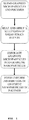
FIG. 1 is a flowchart illustrating various steps that an in situ exfoliation method of fabricating a graphene-reinforced polymer matrix composite may implement. -
FIG. 2 is a graph illustrating the log shear stress versus the log shear strain rate collected for a polymer at three different constant temperatures. -
FIG. 3 illustrates the morphology analysis of 2% graphite exfoliated in polysulfone at mixing times of 3 minutes, 30 minutes, and 90 minutes according to an in situ exfoliation method of the present disclosure. -
FIG. 4 illustrates micrographs of 90G-PMC at various scales and magnification levels according to an in situ exfoliation method of the present disclosure. -
FIG. 5 illustrates a graph of the Debye-Scherrer Equation applied to the average XRD results from each 2% graphite exfoliated in polysulfone according to an in situ exfoliation method of the present disclosure. -
FIG. 6 illustrates a graph depicting the crystal size versus FWHM of 2% graphite exfoliated in polysulfone according to an in situ exfoliation method of the present disclosure. - This disclosure is not limited to the particular systems, methodologies or protocols described, as these may vary. The terminology used in this description is for the purpose of describing the particular versions or embodiments only, and is not intended to limit the scope.
- As used in this document, the singular forms "a," "an," and "the" include plural reference unless the context clearly dictates otherwise. Unless defined otherwise, all technical and scientific terms used herein have the same meanings as commonly understood by one of ordinary skill in the art. All publications mentioned in this document are incorporated by reference. All sizes recited in this document are by way of example only, and the invention is not limited to structures having the specific sizes or dimensions recited below. Nothing in this document is to be construed as an admission that the embodiments described in this document are not entitled to antedate such disclosure by virtue of prior invention. As used herein, the term "comprising" means "including, but not limited to."
- The following term(s) shall have, for purposes of this application, the respective meanings set forth below:
The term "graphene" refers to the name given to a single layer of carbon atoms densely packed into a benzene-ring structure. Graphene, when used alone, may refer to multi-layer graphene, graphene flakes, graphene platelets, and few layer graphene or single layer graphene in a pure and uncontaminated form. - The present invention provides a high efficiency mixing method to transform a polymer composite that contains well-crystallized graphite particles into nano-dispersed single or multi-layer graphene particles. The method involves in situ exfoliation of the graphite layers by compounding in a batch mixer or extruder that impart repetitive, high shear strain rates. In both processes, longer mixing times provide enhanced exfoliation of the graphite into graphene nanoparticles within the polymer matrix composite (PMC). In addition, additives may be used to promote sufficient graphene/polymer bonding, thereby yielding a low density graphene-reinforced polymer matrix composite (G-PMC). The method is low cost to produce a G-PMC that offers numerous property advantages, including increased specific stiffness and strength, enhanced electrical/thermal conductivity, and retention of optical transparency.
- Repeated compounding during a batch mixing process or single screw extrusion is used to progressively transform the initial graphite-particle dispersion into a uniform nano-dispersion of discrete graphene nanoparticles. In some cases, an inert gas or vacuum may be used during processing. The method is described herein as "mechanical" exfoliation to distinguish it from "chemical" exfoliation, which is the primary thrust of much of today's research. An advantage of the mechanical method is that contamination-free graphene-polymer interfaces are formed during high-shear mixing, thus ensuring good interface adhesion or bonding. Other advantages of in situ exfoliation are that it avoids making and handling graphene flakes, as well as dispersing them uniformly in the polymer matrix phase.
- Depending on the number of in situ shear strain events, the method provides multi-layer graphene, graphene flakes, graphene platelets, few layer graphene or single layer graphene in a pure and uncontaminated form. Platelets have diamond-like stiffness and are used for polymer reinforcement. Graphene in any form increases polymer toughness by inhibiting crack propagation as a reinforcement for polymers. Graphene may be used as an additive to polymers and other compositions to provide electrical and thermal conductivity. The thermal conductivity of graphene makes it a desirable additive for thermal management for electronic devices and lasers.
- Graphite, the starting material from which graphene is formed, is composed of a layered planar structure in which the carbon atoms in each layer are arranged in a hexagonal lattice. The planar layers are defined as having an "a" and a "b" axis, with a "c" axis normal to the plane defined by the "a" and "b" axes. The graphene particles produced by the inventive method have an aspect ratio defined by the "a" or "b" axis distance divided by the "c" axis distance. Aspect ratio values for the inventive nanoparticles exceed 25:1 and typically range between 50:1 and 1000:1.
- It should be understood that essentially any polymer inert to graphite capable of imparting sufficient shear strain to exfoliate graphene from the graphite may be used in the method of the present invention. Examples of such polymers include, but are not limited to, polyetheretherketone (PEEK), polyetherketone (PEK), poly-phenylene sulfide (PPS), polyethylene sulfide (PES), polyetherimide (PEI), polyvinylidene fluoride (PVDF), polysulfone (PSU), polycarbonate (PC), polyphenylene ether/oxide, nylons, aromatic thermoplastic polyesters, aromatic polysulfones, thermoplastic polyimides, liquid crystal polymers, thermoplastic elastomers, polyethylene, polypropylene, polystyrene (PS), polymethylmethacrylate (PMMA), polyacrylonitrile (PAN), ultra-high-molecular-weight polyethylene (UHMWPE), polytetrafluoroethylene (PTFE/Teflon), acrylonitrile butadiene styrene (ABS), polycarbonates (PC), polyamides (PA), polyphenylene oxide (PPO), polyphenylene sulfide (PPS), polyoxymethylene plastic (POM/Acetal), polyimides, polyaryletherketones, polyetherimide (PEI), polyvinylchloride (PVC), polyvinylidine fluoride (PVDF), acrylics, polyphenylene sulfide (PPS), polyphenylene oxide (PPO), mixtures thereof, and the like. Polymers capable of wetting the graphite surface may be used as well as high melting point, amorphous polymers in accordance with the method of the present invention.
- The graphene may be produced as a graphene-polymer mixture suitable for use as-is as a G-PMC that can be pelletized by conventional means for subsequent fabrication processing. Alternatively, higher concentrations of graphite may be used at the outset to provide a graphene-polymer masterbatch in concentrated form that can also be pelletized and then used to add graphene to polymer compositions as a reinforcing agent. As a further alternative, the graphene may be separated from the polymer, for example, by combustion or selective dissolution, to provide essentially pure particles of graphene.
- Graphene-reinforced polymers according to the present invention typically contain between about 0.1 and about 30 wt% graphene. More typically, the polymers contain between about 1.0 and about 10 wt% graphene. Polymer masterbatches typically contain between about 5 and about 50 wt% graphene, and more typically between about 10 and about 30 wt% graphene.
- The availability of graphite-rich mineral deposits, containing relatively high concentrations (e.g., about 20%) of well-crystallized graphite, makes for a low cost and virtually inexhaustible source of raw material. As discussed below, the extraction of graphite particles from mined material can be accomplished in a cost-effective manner. Synthetic graphite of high purity and exceptional crystallinity (e.g., pyrolytic graphite) may also be used for the same purpose. However, in this case, the batch mixing or extrusion compounding-induced exfoliation process creates a laminated composite, in which the graphene nanoparticles are oriented over a relatively large area. Such laminated composites may be preferred for specific applications.
- Mechanical exfoliation of graphite within a polymer matrix may be accomplished by a polymer processing technique that imparts repetitive high shear strain events to mechanically exfoliate graphite microparticles into multi- or single-layer graphene nanoparticles within the polymer matrix.
- For purposes of the present invention, graphite micro-particles are defined as graphite in which at least 50% of the graphite consists of multilayer graphite crystals ranging between 1.0 and 1000 microns thick along the c-axis of the lattice structure. Typically 75% of the graphite consists of crystals ranging between 100 and 750 microns thick. Expanded graphite may also be used. Expanded graphite is made by forcing the crystal lattice planes apart in natural flake graphite, thus expanding the graphite, for example, by immersing flake graphite in an acid bath of chromic acid, then concentrated sulfuric acid. Expanded graphite suitable for use in the present invention include expanded graphite with opened edges at the bilayer level, such as MESOGRAF.
- A succession of shear strain events is defined as subjecting the molten polymer to an alternating series of higher and lower shear strain rates over essentially the same time intervals so that a pulsating series of higher and lower shear forces associated with the shear strain rate are applied to the graphite particles in the molten polymer. Higher and lower shear strain rates are defined as a first, higher, shear strain rate that is at least twice the magnitude of a second, lower shear strain rate. The first shear strain rate will range between 100 and 10,000 sec- 1. At least 1,000 to over 10,000,000 alternating pulses of higher and lower shear strain pulses are applied to the molten polymer to form the exfoliated graphene nanoparticles. The number of alternating pulses required to exfoliate graphite particles into graphene particles may be dependent on the original graphite particle dimensions at the beginning of this process, i.e., smaller original graphite particles may need a fewer number of alternating pulses to achieve graphene than larger original graphite particles. This can be readily determined by one of ordinary skill in the art guided by the present specification without undue experimentation.
- After high-shear mixing, the graphene flakes in the molten polymer are uniformly dispersed, randomly oriented, and have high aspect ratio. Orientation of the graphene may be achieved by many different methods. Conventional drawing, rolling, and extrusion methods may be used to directionally align the graphene within the PMC fiber, filament, ribbon, sheet, or any other long-aspect shape. The method to fabricate and characterize a G-PMC is comprised of four main steps and is further described below:
- 1. Extraction of crystalline graphite particles from a mineral source;
- 2. Incorporation of the extracted graphite particles into a polymer matrix phase and conversion of the graphite-containing polymer into a graphene-reinforced polymer matrix composite (G-PMC) by a high efficiency mixing/exfoliation process;
- 3. Morphology analysis to determine the extent of mechanical exfoliation and distribution of multi-layer graphene and graphene nanoparticles; and
- 4. X-ray diffraction analysis to determine multi-layer graphene or graphene crystal size as a function of mechanical exfoliation.
- Highly crystalline graphite may be extracted from graphite ore by a multi-step process, as described below.
- 1. Crushing: A drilled rod of graphite ore from the mine may be placed in a vice and crushed.
- 2. Grinding: The crushed graphite ore may be then ground by mortar and pestle.
- 3. Size Reduction: The ground graphite ore may be placed in a sieve with a 1 mm mesh size and size reduced. Larger pieces that do not pass through the screen may be ground by mortar and pestle and then size reduced through the 1 mm mesh size again. Eventually, all of the material passed through the 1 mm mesh size to obtain graphite ore powder.
- 4. Density Separation by Water: The 1 mm sized powder may be placed in a column filled with water and agitated until a clear separation formed between the more dense portions of the solids and the less dense portions. Graphite is near the density of water (1 g/cm3), while silicon is much more dense (2.33 g/cm3). The uppermost materials are siphoned off with the water and then dried. The dried powder graphite is referred to as Separated Mineral Graphite (SMG).
- In commercial practice, very large crushing and grinding machines are available to produce tonnage quantities of mixed powders, from which the graphite component can be separated by standard floatation methods.
- Referring now to
FIG. 1 , a method according to the present disclosure is depicted in a flow chart illustrating the various steps that an in situ exfoliation method of fabricating a G-PMC may implement. In this method, a polymer that is uniformly blended with micron-sized crystalline graphite particles is subjected to repeated compounding-element processing during batch mixing or extrusion at a temperature where the polymer adheres to the graphite particles. Typical polymers have a heat viscosity (without graphite) greater than 100 cps at the compounding temperature. The compounding temperature will vary with the polymer and can range between room temperature (for polymers that are molten at room temperature) and 600°C. Typical compounding temperatures will range between 180°C and 400°C. - In one embodiment, the extrusion compounding elements are as described in United States Patent No.
6,962,431 , the disclosure of which is incorporated herein by reference, with compounding sections, known as axial fluted extensional mixing elements or spiral fluted extensional mixing elements. The compounding sections act to elongate the flow of the polymer and graphite, followed by repeated folding and stretching of the material. This results in superior distributive mixing, which in turn, causes progressive exfoliation of the graphite particles into discrete graphene nanoparticles. Batch mixers may also be equipped with equivalent mixing elements. - Thus, the effect of each compounding pass is to shear-off graphene layers one after the other, such that the original graphite particles are gradually transformed into a very large number of graphene nanoparticles. After an appropriate number of such passes, the final result is a uniform dispersion of discrete graphene nanoparticles in the polymer matrix phase. Longer mixing times or a larger number of passes through the compounding elements provide smaller graphite crystal size and enhanced exfoliation of graphite into graphene nanoparticles within the polymer matrix, however, the shear events should not be of a duration that would degrade the polymer.
- As the density of graphene nanoparticles increases during multi-pass extrusion, the viscosity of the polymer matrix increases, due to the influence of the growing number of polymer/graphene interfaces. To ensure continued refinement of the composite structure, the extrusion parameters are adjusted to compensate for the higher viscosity of the composite.
- Automated extrusion systems are available to subject the composite material to as many passes as desired, with mixing elements as described in United States Patent No.
6,962,431 , and equipped with a re-circulating stream to direct flow back to the extruder input. Since processing of the graphene-reinforced PMC is direct and involves no handling of graphene particles, fabrication costs are low. - In order to mechanically exfoliate graphite into multi-layer graphene and/or graphene, the shear strain rate generated in the polymer during processing must cause a shear stress in the graphite particles greater than the critical stress required to separate two layers of graphite, or the interlayer shear strength (ISS). The shear strain rate within the polymer is controlled by the type of polymer and the processing parameters, including the geometry of the mixer, processing temperature, and revolutions per minute (RPM).
- The required processing temperature and RPM for a particular polymer is determinable from polymer rheology data given that, at a constant temperature, the shear strain rate (γ̇) is linearly dependent upon RPM, as in Equation 1. The geometry of the mixer appears as the rotor radius, r, and the space between the rotor and the barrel, Δr.

- Polymer rheology data collected for a particular polymer at three different temperatures provides a log shear stress versus log shear strain rate graph, as illustrated in
FIG. 2 . The ISS of graphite ranges between 0.2 MPa - 7 GPa, but a new method has quantified the ISS at 0.14 GPa. Thus, to mechanically exfoliate graphite in a polymer matrix during processing, the required processing temperature, shear strain rate, and RPM is determinable for a particular polymer fromFIG. 2 so that the shear stress within the polymer is equal to or greater than the ISS of graphite. Under typical processing conditions, polymers have sufficient surface energy to behave like the sticky side of scotch tape, and thus are able to share the shear stress between the polymer melt and the graphite particles. - In one embodiment, a method for forming a G-PMC includes distributing graphite microparticles into a molten thermoplastic polymer phase. A succession of shear strain events are then applied to the molten polymer phase so that the molten polymer phase exfoliates the graphite successively with each event until at least 50% of the graphite is exfoliated to form a distribution in the molten polymer phase of single- and multi-layer graphene nanoparticles less than 50 nanometers thick along a c-axis direction.
- In certain embodiments, the graphite particles may be prepared by crushing and grinding a graphite-containing mineral to millimeter-sized dimensions. The millimeter-sized particles may be reduced to micron-sized dimensions using ball milling and attritor milling.
- In certain embodiments, the graphite particles may be extracted from the micron-sized particle mixture by a flotation method. The extracted graphite particles may be incorporated in a polymer matrix using a single screw extruder with axial fluted extensional mixing elements or spiral fluted extensional mixing elements. The graphite-containing polymer matrix is subjected to repeated extrusion as described herein to induce exfoliation of the graphitic material, thus forming a uniform dispersion of graphene nanoparticles in the polymer matrix.
- In other embodiments, the succession of shear strain events may be applied until at least 50% of the graphite is exfoliated to form a distribution in the molten polymer phase of single- and multi-layer graphene nanoparticles less than 10 nanometers thick along the c-axis direction.
- In other embodiments, the succession of shear strain events may be applied until at least 90% of the graphite is exfoliated to form a distribution in the molten polymer phase of single- and multi-layer graphene nanoparticles less than 10 nanometers thick along the c-axis direction.
- In other embodiments, the succession of shear strain events may be applied until at least 80% of the graphite is exfoliated to form a distribution in the molten polymer phase of single- and multi-layer graphene nanoparticles less than 10 nanometers thick along the c-axis direction.
- In other embodiments, the succession of shear strain events may be applied until at least 75% of the graphite is exfoliated to form a distribution in the molten polymer phase of single- and multi-layer graphene nanoparticles less than 10 nanometers thick along the c-axis direction.
- In other embodiments, the succession of shear strain events may be applied until at least 70% of the graphite is exfoliated to form a distribution in the molten polymer phase of single- and multi-layer graphene nanoparticles less than 10 nanometers thick along the c-axis direction.
- In other embodiments, the succession of shear strain events may be applied until at least 60% of the graphite is exfoliated to form a distribution in the molten polymer phase of single- and multi-layer graphene nanoparticles less than 10 nanometers thick along the c-axis direction.
- In other embodiments, the graphite may be doped with other elements to modify the surface chemistry of the exfoliated graphene nanoparticles. The graphite is expanded graphite.
- In other embodiments, the surface chemistry or nanostructure of the dispersed graphite may be modified to enhance bond strength with the polymer matrix to increase strength and stiffness of the graphene composite.
- In other embodiments, directional alignment of the graphene nanoparticles is used to obtain one-, two- or three-dimensional reinforcement of the polymer matrix phase.
- The present invention is further illustrated by the following example, which should not be construed as limiting in any way. While some embodiments have been illustrated and described, it should be understood that changes and modifications can be made therein in accordance with ordinary skill in the art without departing from the invention in its broader aspects as defined in the following claims.
- In one embodiment, a small scale extension mixer with a 10 gram capacity was used to compound 2 % of SMG with Udel P-1700 Polysulfone (PSU) at 332 °C (630 °F) and under vacuum for 3, 30, and 90 minutes. The method is described below. Samples collected for characterization after each length of time are referred to as 3G-PMC, 30G-PMC, 90G-PMC.
- 1. 9.8 grams of PSU were added to the mixer and allowed to become molten.
- 2. 0.2 grams of SMG were added to the molten PSU and mixed.
- 3. After 3 minutes of mixing time, 3 grams of the G-PMC were extruded out of the mixer and collected for characterization.
- 4. 3 grams of 2 % SMG in PSU was added to the mixer and mixed.
- 5. After 30 minutes of mixing time, 3 grams of the G-PMC were extruded out of the mixer and collected for characterization.
- 6. 3 grams of 2 % SMG in PSU was added to the mixer and mixed.
- 7. After 90 minutes of mixing time, 3 grams of the G-PMC were extruded out of the mixer and collected for characterization.
- A Zeiss Sigma Field Emission Scanning Electron Microscope (FESEM) with Oxford EDS was used to determine the degree of mechanical exfoliation of graphite into multi-layer graphene or graphene nanoparticles and the thickness of these particles. An accelerating voltage of 3kV and working distance of approximately 8.5 mm was used during viewing. Prior to viewing, specimens from each sample of 3G-PMC, 30G-PMC, and 90G-PMC were notched, cryogenically fractured to produce a flat fracture surface, placed under vacuum for at least 24 hours, gold coated, and stored under vacuum.
- XRD analysis on each sample of 3G-PMC, 30G-PMC, and 90G-PMC includes four steps: (1) sample preparation, (2) diffraction pattern acquisition, (3) profile fitting, and (4) out-of-plane (D) crystallite sizes calculation according to the Debye-Scherrer equation.
- 1. The samples for XRD analysis were prepared by pressing thin films of each
sample 3G-PMC, 30G-PMC, and 90G-PMC at 230oC and 5,500 psi over a 2 minute time period. Each sample was positioned between aluminum sheets prior to pressing using a Carver Uniaxial Press with heated platens. - 2. Diffraction patterns of the pressed films were acquired using a Philips XPert powder Diffractometer with sample changer (Xpert) at 40kV and 45mA with an incident slit thickness of 0.3 mm from 4° - 70° 2θ and a step size of 0.02° 2θ.
- 3. Diffraction patterns were uploaded into WinPLOTR Powder diffraction graphics tool, without background editing or profile adjustments prior to peak fitting. Single peak fitting was applied at a 2θ range of 26° - 27.5°, using a pseudo-Voigt function and taking into account a global FWHM, global eta (proportion of Lorentz), and linear background. Single peak fitting of the profile provides the full width at half maximum (FWHM) of the relevant peak.
- 4. The average out of-plane crystallite size (D) (sometimes referred to as along the c-axis, and proportional to the number of graphene layers which are stacked) is calculated using the Debye-Scherrer Equation and the (002) FWHM values, for which λ is the X-ray wavelength, coefficient K = 0.89, β is the FWHM in radians, and θ is the diffraction angle. The d-spacing is also calculated.

- The morphology of each sample, 3G-PMC, 30G-PMC, and 90G-PMC, at three different scales (magnification) is shown in
FIG. 3 . In (a-c), a 20 µm scale and 1,000X magnification shows good distribution of multi-layer graphene or graphene within the PSU matrix at each mixing time. In (d-f), a 1 µm scale and 10,000X magnification and (g-i), a 1 µm scale and 50,000X magnification shows mechanically exfoliated graphite within the PSU matrix. In (d-i), micro-folding of the multi-layer graphene or graphene is evident, as well as good bonding between the graphene nanoparticles and the polymer matrix. - The 90G-PMC sample, the sample mixed for the longest time and exposed to the most repetitive shearing, exhibits superior mechanical exfoliation and the smallest crystal size. As shown in
FIG. 4 , mechanical exfoliation has reduced the graphene nanoparticle thickness in the 90G-PMC sample to 8.29 nm. - The Debye-Scherrer equation was applied to the FWHM and d-spacing results obtained from the X-ray diffraction patterns for 3G-PMC, 30G-PMC, and 90G-PMC to provide the crystal thickness (D) of the multi-layer graphene or graphene nanoparticles. The XRD results and crystal thickness appear in Table 1. For the 3G-PMC, 30G-PMC, and 90G-PMC samples, the crystal thickness is 40 nm, 31 nm, and 23 nm; the FWHM is 0.202°, 0.257°, and 0.353°; and the d-spacing is 3.361 nm, 3.353 nm, and 3.387 nm, respectively. The FWHM increases with mixing time, and crystal thickness decreases with mixing time (
FIG. 5 ), which indicates that mechanical exfoliation of the graphite to multi-layer graphene or graphene is occurring and is enhanced over longer mixing times.FIG. 6 shows the decrease in crystal size as a function of FWHM.TABLE 1. Debye-Scherrer Equation applied to the average XRD results from each 2 % Graphite Exfoliated in PSU sample mixed for 3 min, 30 min, and 90 min Sample Mixing Time (min) (d 002) (nm) FWHM (degrees) Average D-Crystal Thickness (nm) Along c-Axis. Direction 3G- PMC 3 0.3361 0.202 40 30G- PMC 30 0.3353 0.257 31 90G-PMC 90 0.3387 0.353 23 - Mechanical exfoliation of the graphite into multi-layer graphene or graphene as a result of the repetitive shear strain action in the polymer processing equipment generates dangling primary and secondary bonds that provide the opportunity for various chemical reactions to occur, which can be exploited to obtain property enhancement of the G-PMC. This represents an advance over prior art conventional methods forming graphene oxides, where the dangling primary and secondary bonds covalently bond with oxygen, which typically remain in these positions even after the graphene oxide is reduced.
- For example, chemical reactions that covalently attach these dangling bonds from the multi-layer graphene or graphene nanoparticles to the polymer matrix would provide superior mechanical properties of the G-PMC. Alternatively, electrical conductivity may be enhanced by chemically linking appropriate band gap materials at the graphene nano-particle edges or by coordinating with conductive metals such as gold, silver, copper, and the like. The graphene-reinforced polymer may then be added to polymers or other compositions to provide or increase electrical conductivity. The bonds may also be coordinated to metals, such as platinum and palladium, to provide a catalyst, with the graphene-reinforced polymer serving as a catalyst support. Other forms of functionalized graphene are disclosed in
U.S. Patent No. 8,096,353 , the disclosure of which is incorporated herein by reference. - The method of the present invention is particularly advantageous because in situ functionalization reactions may be performed during the exfoliation process via one pot reactive compounding.
- The graphene-reinforced polymers may be used as electrodes for lightweight batteries. Other uses include composite boat hulls, aircraft, aerospace systems, transportation vehicles, personnel armor, pressure vessels, reactor chambers, spray coatings, polymer powders for 3-D printing, transparent electrodes for electronic device touch screens, and the like. Addition of 1-2 wt % graphene to a polymer matrix imparts electrical conductivity, while maintaining optical transparency, thus enabling applications in solar panels, flat-panel displays, and for static-discharge control in hospitals.
- Mechanical exfoliation successfully converted 2% graphite melt-blended with PSU into a G-PMC using a repetitive shearing action in the Randcastle Extrusion System's Small Scale Extension Mixer. Results may be improved by machine modification to increase shear; for example, by using a larger diameter mixing element to increase rotational speed and/or by minimizing the spacing between the mixing element and the cylinder wall.
- The design of the existing small batch mixer may be modified to provide higher shear rate, which in turn provides superior mechanical exfoliation of graphite within the polymer matrix. The shear rate, γ̇, is calculated according to
Equation 3, where r is the tooling radius and Δr is the clearance for compounding. Machine modifications are listed in Table 2, along with the maximum achievable shear rate. The newly designed mixer has a maximum shear rate 22 times that of the current mixer, which will provide enhanced mechanical exfoliation of graphite within a polymer matrix at shorter lengths of time. In other words, the crystal size, D, may be reduced to smaller dimensions in a more efficient length of time.
TABLE 2. Modifications of the Randcastle Extrusion System's Small Scale Extension Mixer to provide enhanced mechanical exfoliation Current Randcastle Mixer Improved Randcastle Mixer Tooling Radius (inches) 0.5 1 Clearance for Compounding, Δr (in) 0.04 0.01 Maximum RPM 100 360 Maximum Shear Strain Rate (sec-1) 133 2900 - Randcastle has made modifications to the extruder screw that will better enable mechanical exfoliation of the graphite into multi-layer graphene or graphene in a polymer matrix to fabricate a G-PMC.
- The foregoing examples and description of the preferred embodiments should be taken as illustrating, rather than as limiting the present invention as defined by the claims. As will be readily appreciated, numerous variations and combinations of the features set forth above can be utilized without departing from the present invention as set forth in the claims. Such variations are not regarded as a departure from the spirit and scope of the invention, and all such variations are intended to be included within the scope of the following claims.
- Further and other aspects in accordance with the present invention are enumerated in the following numbered clauses:
- 1. A method for forming a graphene-reinforced polymer matrix composite, comprising:
- (a) distributing graphite microparticles into a molten thermoplastic polymer phase; and
- (b) applying a succession of shear strain events to the molten polymer phase so that the molten polymer phase exfoliates the graphite successively with each event until at least 50% of the graphite is exfoliated to form a distribution in the molten polymer phase of single- and multi-layer graphene nanoparticles less than 50 nanometers thick along a c-axis direction.
- 2. The method of clause 1, wherein the graphite particles may be prepared by crushing and grinding a graphite-containing mineral to millimeter-sized dimensions.
- 3. The method of
clause 2, wherein the millimeter-sized particles may be reduced to micron-sized dimensions using ball milling and attritor milling. - 4. The method of
clause 3, wherein the graphite particles may be extracted from the micron-sized particle mixture by a flotation method. - 5. The method of clause 4, wherein the extracted graphite particles may be incorporated in a polymer matrix using a single screw extruder with axial fluted extensional mixing elements or spiral fluted extensional mixing elements.
- 6. The method of clause 5, wherein the graphite-containing polymer matrix is subjected to repeated extrusion to induce exfoliation of the graphitic material, thus forming a uniform dispersion of graphene nano-particles in the polymer matrix.
- 7. The method of clause 6, wherein the polymer is selected from the group consisting of polyether-etherketones, polyetherketones, polyphenylene sulfides, polyethylene sulfides, polyetherimides, poly-vinylidene fluorides, polysulfones, polycarbonates, polyphenylene ethers/oxides, nylons, aromatic thermo-plastic polyesters, aromatic polysulfones, thermoplastic polyimides, liquid crystal polymers, thermoplastic elastomers, polyethylenes, polypropylenes, polystyrene, polymethylmethacrylate, polyacrylonitrile, ultra-high-molecular-weight polyethylene, polytetrafluoroethylene, acrylonitrile butadiene styrene, polycarbonates, polyamides, polyphenylene oxide, polyphenylene sulfide, polyoxymethylene plastic, polyimides, polyaryletherketones, polyetherimide, polyvinylchloride, polyvinylidine fluoride, acrylics, polyphenylene sulfide, polyphenylene oxide, and mixtures thereof.
- 8. The method of clauses 1 to 6, wherein the succession of shear strain events may be applied until at least 50% of the graphite is exfoliated to form a distribution in the molten polymer phase of single- and multi-layer graphene nanoparticles less than 25 nanometers thick along the c-axis direction.
- 9. The method of clauses 1 to 6, wherein the succession of shear strain events may be applied until at least 50% of the graphite is exfoliated to form a distribution in the molten polymer phase of single- and multi-layer graphene nanoparticles less than 10 nanometers thick along the c-axis direction.
- 10. The method of clauses 1 to 6, wherein the succession of shear strain events may be applied until at least 90% of the graphite is exfoliated to form a distribution in the molten polymer phase of single- and multi-layer graphene nanoparticles less than 10 nanometers thick along the c-axis direction.
- 11. The method of clauses 1 to 6, wherein the succession of shear strain events may be applied until at least 80% of the graphite is exfoliated to form a distribution in the molten polymer phase of single- and multi-layer graphene nanoparticles less than 10 nanometers thick along the c-axis direction.
- 12. The method of clauses 1 to 6, wherein the succession of shear strain events may be applied until at least 75% of the graphite is exfoliated to form a distribution in the molten polymer phase of single- and multi-layer graphene nanoparticles less than 10 nanometers thick along the c-axis direction.
- 13. The method of clauses 1 to 6, wherein the succession of shear strain events may be applied until at least 70% of the graphite is exfoliated to form a distribution in the molten polymer phase of single- and multi-layer graphene nanoparticles less than 10 nanometers thick along the c-axis direction.
- 14. The method of clauses 1 to 6, wherein the succession of shear strain events may be applied until at least 60% of the graphite is exfoliated to form a distribution in the molten polymer phase of single- and multi-layer graphene nanoparticles less than 10 nanometers thick along the c-axis direction.
- 15. The method of clauses 1 to 10, wherein the graphite may be doped with other elements to modify a surface chemistry of the exfoliated graphene nanoparticles.
- 16. The method of clauses 1 to 10, wherein the graphite is expanded graphite.
- 17. The method of clauses 1 to 10, wherein a surface chemistry or nanostructure of the dispersed graphite may be modified to enhance bond strength with the polymer matrix to increase strength and stiffness of the graphene composite.
- 18. The method of clauses 1 to 10, wherein directional alignment of the graphene nanoparticles is used to obtain one-, two- or three-dimensional reinforcement of the polymer matrix phase.
Claims (15)
- A graphene-reinforced polymer matrix composite comprising a distribution in a thermoplastic polymer matrix of mechanically exfoliated, essentially pure and uncontaminated single-layer and multi-layer graphene nanoparticles less than 50 nanometers thick along a c-axis direction and graphite microparticles,
wherein from about 50 % to about 90 % by weight of the microparticles and nanoparticles are single-layer and multi-layer graphene nanoparticles and the composite comprises from about 0.1% to about 30% by weight of essentially pure and uncontaminated graphene, and
wherein the composite comprises contamination-free graphene-polymer interfaces and wherein the polymer adheres to or is covalently bonded to the graphene-polymer interfaces. - The graphene-reinforced polymer matrix composite of claim 1, wherein the composite comprises at least one thermoplastic polymer molecule bonded or adhered to one or more mechanically exfoliated single- or multi-layer graphene nanoparticles.
- The graphene-reinforced polymer matrix composite of any one of the preceding claims, wherein the composite comprises at least one single- or multi-layer graphene nanoparticle covalently bonded to one or more thermoplastic polymer molecules.
- The graphene-reinforced polymer matrix composite of any one of the preceding claims, wherein the single- and multi-layer graphene nanoparticles comprise fractures formed across the basal plane of the single- and multi-layer graphene nanoparticles.
- The graphene-reinforced polymer matrix composite of claim 4, wherein the edges of the fractures comprise reactive free radical bonding sites that are directly covalently bonded to said one or more molten thermoplastic polymers to provide a composite wherein thermoplastic polymer chains are directly covalently bonded to, and inter-molecularly cross-linked by, said single- and multi-layer graphene nanoparticles mechanically exfoliated in said thermoplastic polymer.
- The graphene-reinforced polymer matrix composite of any one of the preceding claims, wherein the single-layer and multi-layer graphene nanoparticles comprise essentially pure and uncontaminated single-layer and multi-layer graphene nanoparticles less than 25 nanometers thick along a c-axis direction.
- The graphene-reinforced polymer matrix composite of any one of the preceding claims, wherein the single-layer and multi-layer graphene nanoparticles comprise essentially pure and uncontaminated single-layer and multi-layer graphene nanoparticles less than 10 nanometers thick along a c-axis direction.
- The graphene-reinforced polymer matrix composite of any one of the preceding claims, wherein said composite contains between about 2% and about 30% by weight of graphene.
- The graphene-reinforced polymer matrix composite of any one of the preceding claims, wherein said composite contains between about 10% and about 30% by weight of graphene.
- The graphene-reinforced polymer matrix composite of any one of the preceding claims, wherein said composite comprises residual graphite microparticles.
- The graphene-reinforced polymer matrix composite of any one of the preceding claims, wherein a surface chemistry or nanostructure of the microparticles and nanoparticles is modified to enhance bond strength with the polymer matrix to increase strength and stiffness of the composite.
- The graphene-reinforced polymer matrix composite of any one of the preceding claims, wherein the polymer is selected from the group consisting of polyether-etherketones, polyetherketones, polyphenylene sulfides, polyethylene sulfides, polyetherimides, polyvinylidene fluorides, polysulfones, polycarbonates, polyphenylene ethers/oxides, aromatic thermoplastic polyesters, aromatic polysulfones, thermoplastic polyimides, liquid crystal polymers, thermoplastic elastomers, polypropylenes, polystyrene, polymethylmethacrylate, polyacrylonitrile, ultra-high-molecular-weight polyethylene, polytetrafluoroethylene, acrylonitrile butadiene styrene, polyamides, polyoxymethylene, polyaryletherketones, polyvinylchloride, polyvinylidine fluoride, and mixtures thereof.
- A product comprising the graphene-reinforced polymer matrix composite of any one of the preceding claims, wherein the composite contains 0.01-2 wt% of the graphene nanoparticles and the product is:(a) an electrode for lightweight batteries, boat hull, aircraft, aerospace system, transportation vehicle, item of personnel armor, pressure vessel, reactor chamber, spray coating, polymer powder for 3-D printing, or transparent electrode for electronic device touch screen; or(b) a solar panel, flat-panel display, or static-discharge control device.
- An automotive, aircraft, watercraft or aerospace part formed from the graphene-reinforced polymer matrix composite of any one of claims 1-13.
- The automotive, aircraft, watercraft or aerospace part of claim 14, wherein the part is an engine part.
Applications Claiming Priority (3)
| Application Number | Priority Date | Filing Date | Title |
|---|---|---|---|
| US201261716461P | 2012-10-19 | 2012-10-19 | |
| EP13846759.2A EP2909028B1 (en) | 2012-10-19 | 2013-03-14 | In situ exfoliation method to fabricate a graphene-reinforced polymer matrix composite |
| PCT/US2013/031495 WO2014062226A1 (en) | 2012-10-19 | 2013-03-14 | In situ exfoliation method to fabricate a graphene-reinforced polymer matrix composite |
Related Parent Applications (1)
| Application Number | Title | Priority Date | Filing Date |
|---|---|---|---|
| EP13846759.2A Division EP2909028B1 (en) | 2012-10-19 | 2013-03-14 | In situ exfoliation method to fabricate a graphene-reinforced polymer matrix composite |
Publications (1)
| Publication Number | Publication Date |
|---|---|
| EP3603956A1 true EP3603956A1 (en) | 2020-02-05 |
Family
ID=50488626
Family Applications (2)
| Application Number | Title | Priority Date | Filing Date |
|---|---|---|---|
| EP13846759.2A Active EP2909028B1 (en) | 2012-10-19 | 2013-03-14 | In situ exfoliation method to fabricate a graphene-reinforced polymer matrix composite |
| EP19199400.3A Pending EP3603956A1 (en) | 2012-10-19 | 2013-03-14 | Graphene-reinforced polymer matrix composite by an in situ exfoliation method |
Family Applications Before (1)
| Application Number | Title | Priority Date | Filing Date |
|---|---|---|---|
| EP13846759.2A Active EP2909028B1 (en) | 2012-10-19 | 2013-03-14 | In situ exfoliation method to fabricate a graphene-reinforced polymer matrix composite |
Country Status (9)
| Country | Link |
|---|---|
| US (2) | US9896565B2 (en) |
| EP (2) | EP2909028B1 (en) |
| JP (4) | JP6328646B2 (en) |
| KR (2) | KR102239142B1 (en) |
| CN (2) | CN104884243B (en) |
| CA (1) | CA2888865C (en) |
| HK (1) | HK1214209A1 (en) |
| MX (1) | MX363449B (en) |
| WO (1) | WO2014062226A1 (en) |
Cited By (1)
| Publication number | Priority date | Publication date | Assignee | Title |
|---|---|---|---|---|
| EP4282905A1 (en) | 2022-05-24 | 2023-11-29 | Institut "Jozef Stefan" | Preparation process of graphene dispersion in pdms with the simultaneous use of ultrasound and vacuum |
Families Citing this family (70)
| Publication number | Priority date | Publication date | Assignee | Title |
|---|---|---|---|---|
| KR101625311B1 (en) | 2011-10-27 | 2016-05-27 | 갈모어, 인코포레이티드 | Composite graphene structures |
| US11479652B2 (en) | 2012-10-19 | 2022-10-25 | Rutgers, The State University Of New Jersey | Covalent conjugates of graphene nanoparticles and polymer chains and composite materials formed therefrom |
| CN104884243B (en) | 2012-10-19 | 2017-07-18 | 新泽西鲁特格斯州立大学 | Prepare the stripping method in situ of the polymer matrix composites of graphene reinforcement |
| WO2014138587A1 (en) | 2013-03-08 | 2014-09-12 | Garmor, Inc. | Graphene entrainment in a host |
| WO2014138596A1 (en) | 2013-03-08 | 2014-09-12 | Garmor, Inc. | Large scale oxidized graphene production for industrial applications |
| KR102292918B1 (en) * | 2013-04-18 | 2021-08-24 | 럿거스, 더 스테이트 유니버시티 오브 뉴저지 | In situ exfoliation method to fabricate a graphene-reinforced polymer matrix composite |
| EP3920200A1 (en) | 2014-05-05 | 2021-12-08 | 3D Glass Solutions, Inc. | 2d and 3d inductors antenna and transformers fabricating photoactive substrates |
| US9442514B1 (en) | 2014-07-23 | 2016-09-13 | Google Inc. | Graphite layer between carbon layers |
| KR102435617B1 (en) | 2014-07-30 | 2022-08-24 | 럿거스, 더 스테이트 유니버시티 오브 뉴저지 | Graphine-reinforced polymer matrix composites |
| KR101902753B1 (en) | 2014-08-18 | 2018-10-02 | 갈모어 인코포레이티드 | Graphite oxide entrainment in cement and asphalt composite |
| CN104445158B (en) * | 2014-10-23 | 2016-05-04 | 江阴碳谷科技有限公司 | Graphene stripping off device, Graphene production system and the method for producing Graphene |
| WO2016106312A2 (en) * | 2014-12-22 | 2016-06-30 | Reliance Industries Limited | Graphite exfoliation in resin |
| JP6499450B2 (en) * | 2015-01-07 | 2019-04-10 | 株式会社日本触媒 | Graphene oxide composite composition |
| KR101980519B1 (en) * | 2015-03-13 | 2019-05-22 | 유니버시티 오브 센트럴 플로리다 리서치 파운데이션, 인코포레이티드 | Uniform dispersion of graphene nanoparticles in host |
| WO2016154057A1 (en) | 2015-03-23 | 2016-09-29 | Garmor Inc. | Engineered composite structure using graphene oxide |
| US11482348B2 (en) | 2015-06-09 | 2022-10-25 | Asbury Graphite Of North Carolina, Inc. | Graphite oxide and polyacrylonitrile based composite |
| EP3353838B1 (en) | 2015-09-21 | 2023-06-07 | Asbury Graphite of North Carolina, Inc. | Low-cost, high-performance composite bipolar plate |
| CN105271210B (en) * | 2015-11-27 | 2017-04-12 | 成都新柯力化工科技有限公司 | Method for preparing graphene from thermoplastic graphite material |
| US9926427B2 (en) * | 2015-12-10 | 2018-03-27 | Nanotek Instruments, Inc. | Chemical-free production of graphene-reinforced polymer matrix composites |
| CN105417535B (en) * | 2015-12-29 | 2017-05-31 | 成都新柯力化工科技有限公司 | A kind of method that grapheme material is prepared by stretching |
| CN105502367B (en) * | 2015-12-31 | 2017-09-22 | 成都新柯力化工科技有限公司 | A kind of method that utilization jelly drawing prepares graphene |
| KR101982572B1 (en) * | 2016-01-20 | 2019-05-27 | 주식회사 엘지화학 | Method for manufacturing carbon nanotube pellet |
| JP7071609B2 (en) | 2016-02-25 | 2022-05-19 | スリーディー グラス ソリューションズ,インク | Capacitor array for manufacturing 3D capacitors and photoactive substrates |
| WO2017177171A1 (en) | 2016-04-08 | 2017-10-12 | 3D Glass Solutions, Inc. | Methods of fabricating photosensitive substrates suitable for optical coupler |
| CN107459745A (en) * | 2016-06-05 | 2017-12-12 | 天津大学 | A kind of promotion method of the Kynoar alpha-crystal form to γ crystal transfers |
| CN107629454A (en) * | 2016-07-19 | 2018-01-26 | 丹阳市飞利健身器材有限公司 | A kind of roller skate pulley |
| US11702518B2 (en) | 2016-07-22 | 2023-07-18 | Rutgers, The State University Of New Jersey | In situ bonding of carbon fibers and nanotubes to polymer matrices |
| CA3031729C (en) * | 2016-07-22 | 2021-12-21 | Rutgers, The State University Of New Jersey | In situ bonding of carbon fibers and nanotubes to polymer matrices |
| DE112017004473T5 (en) * | 2016-09-06 | 2019-06-27 | Regents Of The University Of Minnesota | SYNERGISTIC VIABILITY IMPROVEMENT OF EPOXY MODIFIED WITH GRAPHS AND BLOCK COPOLYMER |
| US11214658B2 (en) | 2016-10-26 | 2022-01-04 | Garmor Inc. | Additive coated particles for low cost high performance materials |
| CN106928448B (en) | 2017-04-06 | 2017-12-15 | 常州恒利宝纳米新材料科技有限公司 | The continuous production equipment and preparation method of a kind of graphene composite material |
| US11101532B2 (en) | 2017-04-28 | 2021-08-24 | 3D Glass Solutions, Inc. | RF circulator |
| CN107226467B (en) * | 2017-06-19 | 2018-03-20 | 成都新柯力化工科技有限公司 | A kind of method that simultaneously dispersed graphite alkene is prepared using supercritical fluid |
| CA3067812C (en) | 2017-07-07 | 2023-03-14 | 3D Glass Solutions, Inc. | 2d and 3d rf lumped element devices for rf system in a package photoactive glass substrates |
| CN107415211B (en) * | 2017-07-14 | 2019-05-21 | 成都新柯力化工科技有限公司 | A method of efficiently dispersing graphene in polymer |
| GB201715387D0 (en) | 2017-09-22 | 2017-11-08 | Cambridge Entpr Ltd | Treatment of polymer particles |
| CN107698753B (en) * | 2017-10-11 | 2021-01-05 | 三门县鸿远塑业有限公司 | High-pressure atomization method for preparing graphene dispersion liquid and polymerization method for preparing graphene nylon by using graphene dispersion liquid |
| CN108047822B (en) * | 2017-10-27 | 2019-09-03 | 广东烯谷碳源新材料有限公司 | Utilize the method for shear thickening system removing preparing graphite alkene heat conduction and heat radiation composite material |
| CN107814380B (en) * | 2017-10-27 | 2019-07-23 | 中南民族大学 | Utilize the method for shear thickening system removing preparing graphite alkene |
| CA3084818C (en) | 2017-12-15 | 2023-01-17 | 3D Glass Solutions, Inc. | Coupled transmission line resonate rf filter |
| CN108047363A (en) * | 2017-12-19 | 2018-05-18 | 吴丹 | A kind of supercritical polymerization polystyrene/graphene 3D printing spherical powder and preparation method thereof |
| KR102600200B1 (en) | 2018-01-04 | 2023-11-10 | 3디 글래스 솔루션즈 인코포레이티드 | Impedance matching conductive structure for high-efficiency RF circuits |
| US11479653B2 (en) | 2018-01-16 | 2022-10-25 | Rutgers, The State University Of New Jersey | Use of graphene-polymer composites to improve barrier resistance of polymers to liquid and gas permeants |
| JP7179858B2 (en) * | 2018-01-26 | 2022-11-29 | エルジー エナジー ソリューション リミテッド | Conductive material, electrode-forming slurry containing the same, electrode, and lithium secondary battery manufactured using the same |
| CN108586718B (en) * | 2018-03-20 | 2020-06-12 | 青岛科技大学 | Graphene/polyester thermoplastic elastomer composite material and preparation method thereof |
| EP3643148A4 (en) | 2018-04-10 | 2021-03-31 | 3D Glass Solutions, Inc. | Rf integrated power condition capacitor |
| WO2019231947A1 (en) | 2018-05-29 | 2019-12-05 | 3D Glass Solutions, Inc. | Low insertion loss rf transmission line |
| CA3112608C (en) | 2018-09-17 | 2021-12-28 | 3D Glass Solutions, Inc. | High efficiency compact slotted antenna with a ground plane |
| US11565774B2 (en) | 2018-10-03 | 2023-01-31 | Adam Jon Noah | Additive manufactured water resistant closed-cell lattice structure for marine hull cavities |
| DE202018106258U1 (en) * | 2018-10-15 | 2020-01-20 | Rutgers, The State University Of New Jersey | Nano-graphite sponges |
| US10971281B2 (en) * | 2018-11-27 | 2021-04-06 | Global Graphene Group, Inc. | Conducting polymer composite containing ultra-low loading of graphene |
| AU2019416327B2 (en) | 2018-12-28 | 2021-12-09 | 3D Glass Solutions, Inc. | Annular capacitor RF, microwave and MM wave systems |
| CA3107810A1 (en) | 2018-12-28 | 2020-07-02 | 3D Glass Solutions, Inc. | Heterogenous integration for rf, microwave and mm wave systems in photoactive glass substrates |
| WO2020206323A1 (en) | 2019-04-05 | 2020-10-08 | 3D Glass Solutions, Inc. | Glass based empty substrate integrated waveguide devices |
| US11373908B2 (en) | 2019-04-18 | 2022-06-28 | 3D Glass Solutions, Inc. | High efficiency die dicing and release |
| US11807757B2 (en) | 2019-05-07 | 2023-11-07 | Rutgers, The State University Of New Jersey | Economical multi-scale reinforced composites |
| US11791061B2 (en) | 2019-09-12 | 2023-10-17 | Asbury Graphite North Carolina, Inc. | Conductive high strength extrudable ultra high molecular weight polymer graphene oxide composite |
| TWI786340B (en) * | 2019-10-08 | 2022-12-11 | 紐澤西州立羅格斯大學 | Covalent conjugates of graphene nanoparticles and polymer chains, composite materials formed therefrom, and a method of fabrication thereof |
| JP2023504689A (en) * | 2019-12-27 | 2023-02-06 | 桐郷市小老板特種塑料制品有限公司 | Single-layer graphene-containing solidified product, single-layer graphene and preparation method thereof, single-layer graphene-containing product |
| US11577665B2 (en) | 2020-02-27 | 2023-02-14 | Cpk Interior Products | Urethane and graphene interior trim panel |
| EP3875429A1 (en) | 2020-03-03 | 2021-09-08 | Avanzare Innovacion Tencologica S.L. | Procedure to produce graphene and graphenic materials |
| WO2021211855A1 (en) | 2020-04-17 | 2021-10-21 | 3D Glass Solutions, Inc. | Broadband inductor |
| WO2021262747A1 (en) * | 2020-06-25 | 2021-12-30 | Ciparro Nicholas L | Methods of forming a nanocomposite fiber and related mixture and nanocomposite fibers |
| KR102366152B1 (en) * | 2020-08-19 | 2022-02-21 | 송재현 | Method for preparing graphene composite matrix including graphene dispersed in polymer resin and graphene composite matrix prepared thereby |
| EP3970489A1 (en) | 2020-09-18 | 2022-03-23 | CpK Interior Products Inc. | Graphene-based antiviral polymer |
| CN114763261A (en) * | 2021-01-14 | 2022-07-19 | 中国科学院大连化学物理研究所 | Method for preparing graphene material and graphene material obtained by method |
| CN114763428A (en) * | 2021-01-14 | 2022-07-19 | 中国科学院大连化学物理研究所 | Method for preparing polymer and graphene composite material, composite material and base resin obtained by method |
| GB202101925D0 (en) * | 2021-02-11 | 2021-03-31 | Cami Consultancy Ltd | Graphene production method |
| US11820664B2 (en) * | 2021-08-03 | 2023-11-21 | Schlumberger Technology Corporation | Graphene-based fluid system component |
| CN115490889A (en) * | 2022-08-26 | 2022-12-20 | 四川大学 | Method for realizing in-situ stripping of two-dimensional filler by using high-elasticity polymer |
Citations (3)
| Publication number | Priority date | Publication date | Assignee | Title |
|---|---|---|---|---|
| US6962431B1 (en) | 2000-11-08 | 2005-11-08 | Randcastle Extrusion System, Inc. | Extruder mixer |
| EP2287244A1 (en) * | 2009-08-17 | 2011-02-23 | Laird Technologies, Inc. | Highly thermally-conductive moldable thermoplastic composites and compositions |
| US8096353B2 (en) | 2005-12-16 | 2012-01-17 | Schlumberger Technology Corporation | Oilfield nanocomposites |
Family Cites Families (60)
| Publication number | Priority date | Publication date | Assignee | Title |
|---|---|---|---|---|
| CA2135322C (en) | 1993-11-10 | 2001-02-06 | Hiroshi Sugahara | Method for producing a fiber-reinforced thermoplastic resin foamed product |
| JP3419093B2 (en) | 1994-08-11 | 2003-06-23 | 三菱化学株式会社 | Thermoplastic resin composition, method for producing the same, and electromagnetic wave shield molded product comprising the composition |
| CN1433443B (en) | 1999-12-07 | 2010-05-12 | 威廉马歇莱思大学 | Oriented nanofibers embedded in polymer matrix |
| US6660241B2 (en) | 2000-05-01 | 2003-12-09 | Saint-Gobain Ceramics & Plastics, Inc. | Highly delaminated hexagonal boron nitride powders, process for making, and uses thereof |
| JP3958137B2 (en) * | 2001-08-20 | 2007-08-15 | 大塚化学ホールディングス株式会社 | Resin composition |
| US20050070658A1 (en) * | 2003-09-30 | 2005-03-31 | Soumyadeb Ghosh | Electrically conductive compositions, methods of manufacture thereof and articles derived from such compositions |
| US20050186378A1 (en) | 2004-02-23 | 2005-08-25 | Bhatt Sanjiv M. | Compositions comprising carbon nanotubes and articles formed therefrom |
| JP4245514B2 (en) | 2004-05-24 | 2009-03-25 | 日信工業株式会社 | Carbon fiber composite material and method for producing the same, method for producing carbon fiber composite metal material, method for producing carbon fiber composite non-metal material |
| US8048940B2 (en) | 2004-07-09 | 2011-11-01 | Vanderbilt University | Reactive graphitic carbon nanofiber reinforced polymeric composites showing enhanced flexural strength |
| US20060208384A1 (en) * | 2005-03-17 | 2006-09-21 | "H2Economy" Cjsc | Method for producing an electroconductive composite material |
| US20110223405A1 (en) | 2005-11-18 | 2011-09-15 | Northwestern University | Composite polymer film with graphene nanosheets as highly effective barrier property enhancers |
| WO2007145918A2 (en) | 2006-06-05 | 2007-12-21 | University Of Akron | Ultrasound assisted continuous process for dispersion of nanofibers and nanotubes in polymers |
| BRPI0621791A2 (en) * | 2006-07-05 | 2011-12-20 | Owens Corning Intellectual Cap | polymeric foams containing multifunctional layered nano graphite |
| CN100434458C (en) * | 2006-07-12 | 2008-11-19 | 扬州大学 | Polyester/graphite nano-conductive composite material and its preparation method |
| US7745528B2 (en) | 2006-10-06 | 2010-06-29 | The Trustees Of Princeton University | Functional graphene-rubber nanocomposites |
| JP5207351B2 (en) * | 2007-03-23 | 2013-06-12 | 独立行政法人産業技術総合研究所 | Melt-kneaded product, resin molded product and method for producing the same |
| US7824651B2 (en) * | 2007-05-08 | 2010-11-02 | Nanotek Instruments, Inc. | Method of producing exfoliated graphite, flexible graphite, and nano-scaled graphene platelets |
| EP2176163B1 (en) | 2007-08-01 | 2017-10-25 | Dow Global Technologies LLC | Highly efficient process for manufacture of exfoliated graphene |
| WO2009029984A1 (en) * | 2007-09-03 | 2009-03-12 | Newsouth Innovations Pty Limited | Graphene |
| DE102007049439A1 (en) | 2007-09-27 | 2009-04-02 | Electrovac Ag | Plastic composite material and method for its production |
| US7906053B1 (en) | 2008-02-21 | 2011-03-15 | Northwestern University | Polymer-graphite nanocomposites via solid-state shear pulverization |
| EP2262727A2 (en) | 2008-02-28 | 2010-12-22 | Basf Se | Graphite nanoplatelets and compositions |
| WO2009126592A2 (en) | 2008-04-07 | 2009-10-15 | Vorbeck Materials Corp. | Fuel system components |
| WO2009143405A2 (en) | 2008-05-22 | 2009-11-26 | The University Of North Carolina At Chapel Hill | Synthesis of graphene sheets and nanoparticle composites comprising same |
| WO2010007763A1 (en) | 2008-07-15 | 2010-01-21 | パナソニック株式会社 | Radio receiving apparatus, and extra-use-unit-band reference signal measurement method |
| TW201012749A (en) | 2008-08-19 | 2010-04-01 | Univ Rice William M | Methods for preparation of graphene nanoribbons from carbon nanotubes and compositions, thin films and devices derived therefrom |
| KR101074027B1 (en) * | 2009-03-03 | 2011-10-17 | 한국과학기술연구원 | Graphene composite nanofiber and the preparation method thereof |
| US20120142832A1 (en) | 2009-04-03 | 2012-06-07 | Vorbeck Materials Corp. | Polymeric Compositions Containing Graphene Sheets and Graphite |
| KR101161715B1 (en) * | 2009-06-08 | 2012-07-02 | 박용훈 | preparing method for CNT polymer compound which CNT is highly and homogeneously concentrated and CNT polymer compound thereof |
| US20110133134A1 (en) | 2009-06-09 | 2011-06-09 | Vorbeck Materials Corp. | Crosslinkable and Crosslinked Compositions of Olefin Polymers and Graphene Sheets |
| US8652362B2 (en) | 2009-07-23 | 2014-02-18 | Nanotek Instruments, Inc. | Nano graphene-modified curing agents for thermoset resins |
| KR101090517B1 (en) * | 2009-08-17 | 2011-12-08 | 성균관대학교산학협력단 | Nanocarbon-polymer composites and method for preparing the same |
| IT1396193B1 (en) * | 2009-10-07 | 2012-11-16 | Polimeri Europa Spa | EXPANDABLE THERMOPLASTIC NANOCOMPOSITE POLYMER COMPOSITIONS WITH IMPROVED THERMAL INSULATION CAPACITY. |
| IT1396918B1 (en) | 2009-11-03 | 2012-12-20 | Polimeri Europa Spa | PROCEDURE FOR THE PREPARATION OF GRAPHENIC NANOPIASTRINES WITH HIGH LEVELABILITY IN LOW POLARITY POLYMER MATRICES AND THEIR POLYMERIC COMPOSITIONS |
| EP2550332B1 (en) | 2010-03-23 | 2018-05-16 | Solvay SA | Polymer compositions comprising semi-aromatic polyamides and graphene materials |
| FR2959231B1 (en) * | 2010-04-22 | 2012-04-20 | Arkema France | THERMOPLASTIC AND / OR ELASTOMERIC COMPOSITE MATERIAL BASED ON CARBON NANOTUBES AND GRAPHICS |
| CN101817516A (en) * | 2010-05-21 | 2010-09-01 | 哈尔滨工业大学 | Method for preparing graphene or graphene oxide by using high-efficiency and low-cost mechanical stripping |
| KR20120009978A (en) * | 2010-07-23 | 2012-02-02 | 현대자동차주식회사 | Manufacturing Method of Polymer Nanocomposite article by using Aligned Carbonnanotube |
| DE102010032885A1 (en) | 2010-07-30 | 2012-02-02 | Daimler Ag | Fastening device for a fiber-reinforced plastic profile |
| EP2603454B2 (en) | 2010-08-11 | 2020-11-25 | Imerys Graphite & Carbon Switzerland S.A. | Ground expanded graphite agglomerates, methods of making, and applications of the same |
| WO2012029946A1 (en) * | 2010-09-03 | 2012-03-08 | 積水化学工業株式会社 | Resin composite material and method for producing resin composite material |
| US8420042B2 (en) * | 2010-09-21 | 2013-04-16 | High Temperature Physics, Llc | Process for the production of carbon graphenes and other nanomaterials |
| TW201219447A (en) | 2010-10-12 | 2012-05-16 | Solvay | Polymer compositions comprising poly(arylether ketone)s and graphene materials |
| JP5176001B1 (en) | 2011-03-30 | 2013-04-03 | 積水化学工業株式会社 | Resin composite material |
| US8167190B1 (en) | 2011-05-06 | 2012-05-01 | Lockheed Martin Corporation | Electrically conductive polymer compositions containing metal particles and a graphene and methods for production and use thereof |
| JP5953014B2 (en) | 2011-07-08 | 2016-07-13 | 積水化学工業株式会社 | Flame retardant resin composition, flame retardant resin sheet and flame retardant multilayer sheet |
| KR101245815B1 (en) | 2011-07-14 | 2013-03-21 | 국립대학법인 울산과학기술대학교 산학협력단 | Edge-functionalized graphite via mechanic-chemical process and Manufacture of Its |
| WO2013013070A2 (en) | 2011-07-21 | 2013-01-24 | Entegris, Inc. | Nanotube and finely milled carbon fiber polymer composite compositions and methods of making |
| WO2013058181A1 (en) | 2011-10-18 | 2013-04-25 | 積水化学工業株式会社 | Method for producing resin composite material, and resin composite material |
| JP2013233790A (en) | 2012-04-11 | 2013-11-21 | Sekisui Chem Co Ltd | Method for manufacturing resin molded article, and resin molded article |
| CN102675806A (en) * | 2012-06-11 | 2012-09-19 | 合肥博发新材料科技有限公司 | PP (polypropylene)/ expanded graphite heat conducting composite material and preparation method thereof |
| CN104884243B (en) | 2012-10-19 | 2017-07-18 | 新泽西鲁特格斯州立大学 | Prepare the stripping method in situ of the polymer matrix composites of graphene reinforcement |
| US10060019B2 (en) | 2012-11-16 | 2018-08-28 | The Boeing Company | Thermal spray coated reinforced polymer composites |
| GB201304770D0 (en) | 2013-03-15 | 2013-05-01 | Provost Fellows Foundation Scholars And The Other Members Of Board Of | A scalable process for producing exfoliated defect-free, non-oxidised 2-dimens ional materials in large quantities |
| KR102292918B1 (en) | 2013-04-18 | 2021-08-24 | 럿거스, 더 스테이트 유니버시티 오브 뉴저지 | In situ exfoliation method to fabricate a graphene-reinforced polymer matrix composite |
| ES2534575B1 (en) | 2013-09-24 | 2016-01-14 | Consejo Superior De Investigaciones Científicas (Csic) | GRAPHITE EXFOLIATION WITH DEEP EUTETIC SOLVENTS |
| KR102435617B1 (en) | 2014-07-30 | 2022-08-24 | 럿거스, 더 스테이트 유니버시티 오브 뉴저지 | Graphine-reinforced polymer matrix composites |
| WO2016106312A2 (en) | 2014-12-22 | 2016-06-30 | Reliance Industries Limited | Graphite exfoliation in resin |
| CN104945659A (en) | 2015-06-29 | 2015-09-30 | 殷明 | Novel CNT (carbon nanotube) surface treatment method and application thereof in preparing polymer/CNT nano composite material |
| US10685763B2 (en) | 2016-01-19 | 2020-06-16 | Xerox Corporation | Conductive polymer composite |
-
2013
- 2013-03-14 CN CN201380066787.5A patent/CN104884243B/en active Active
- 2013-03-14 CN CN201710479193.7A patent/CN107400246B/en active Active
- 2013-03-14 MX MX2015004975A patent/MX363449B/en unknown
- 2013-03-14 US US14/437,040 patent/US9896565B2/en active Active
- 2013-03-14 JP JP2015537684A patent/JP6328646B2/en active Active
- 2013-03-14 WO PCT/US2013/031495 patent/WO2014062226A1/en active Application Filing
- 2013-03-14 KR KR1020157013193A patent/KR102239142B1/en active IP Right Grant
- 2013-03-14 CA CA2888865A patent/CA2888865C/en active Active
- 2013-03-14 EP EP13846759.2A patent/EP2909028B1/en active Active
- 2013-03-14 KR KR1020217010177A patent/KR102398191B1/en active IP Right Grant
- 2013-03-14 EP EP19199400.3A patent/EP3603956A1/en active Pending
-
2016
- 2016-02-26 HK HK16102272.7A patent/HK1214209A1/en unknown
-
2018
- 2018-02-20 US US15/900,137 patent/US11098175B2/en active Active
- 2018-04-18 JP JP2018080202A patent/JP6633676B2/en active Active
-
2019
- 2019-12-12 JP JP2019224769A patent/JP2020063446A/en active Pending
-
2022
- 2022-08-05 JP JP2022125588A patent/JP2022174044A/en active Pending
Patent Citations (3)
| Publication number | Priority date | Publication date | Assignee | Title |
|---|---|---|---|---|
| US6962431B1 (en) | 2000-11-08 | 2005-11-08 | Randcastle Extrusion System, Inc. | Extruder mixer |
| US8096353B2 (en) | 2005-12-16 | 2012-01-17 | Schlumberger Technology Corporation | Oilfield nanocomposites |
| EP2287244A1 (en) * | 2009-08-17 | 2011-02-23 | Laird Technologies, Inc. | Highly thermally-conductive moldable thermoplastic composites and compositions |
Non-Patent Citations (3)
| Title |
|---|
| -: "Randcastle Extrusion Systems, Inc.", 1 November 2006 (2006-11-01), XP055279030, Retrieved from the Internet <URL:http://www.feedscrewdesigns.com/ubb/Forum1/HTML/000521.html> [retrieved on 20160609] * |
| CHENLU BAO ET AL: "Preparation of graphene by pressurized oxidation and multiplex reduction and its polymer nanocomposites by masterbatch-based melt blending", JOURNAL OF MATERIALS CHEMISTRY, vol. 22, no. 13, 1 January 2012 (2012-01-01), GB, pages 6088, XP055278909, ISSN: 0959-9428, DOI: 10.1039/c2jm16203b * |
| WAKABAYASHI K ET AL: "Polymer - Graphite nanocomposites: Effective dispersion and major property enhancement via solid-state shear pulverization", MACROMOLECULES, AMERICAN CHEMICAL SOCIETY, US, vol. 41, no. 6, 29 February 2008 (2008-02-29), pages 1905 - 1908, XP002743181, ISSN: 0024-9297, [retrieved on 20080229], DOI: 10.1021/MA071687B * |
Cited By (1)
| Publication number | Priority date | Publication date | Assignee | Title |
|---|---|---|---|---|
| EP4282905A1 (en) | 2022-05-24 | 2023-11-29 | Institut "Jozef Stefan" | Preparation process of graphene dispersion in pdms with the simultaneous use of ultrasound and vacuum |
Also Published As
| Publication number | Publication date |
|---|---|
| CN107400246B (en) | 2021-10-01 |
| US9896565B2 (en) | 2018-02-20 |
| CN104884243A (en) | 2015-09-02 |
| CA2888865A1 (en) | 2014-04-24 |
| EP2909028A1 (en) | 2015-08-26 |
| JP2020063446A (en) | 2020-04-23 |
| KR20150070391A (en) | 2015-06-24 |
| EP2909028B1 (en) | 2019-09-25 |
| CA2888865C (en) | 2020-05-12 |
| BR112015008949A2 (en) | 2017-07-04 |
| HK1214209A1 (en) | 2016-07-22 |
| JP6328646B2 (en) | 2018-05-23 |
| CN107400246A (en) | 2017-11-28 |
| JP2018138667A (en) | 2018-09-06 |
| KR102239142B1 (en) | 2021-04-09 |
| JP2022174044A (en) | 2022-11-22 |
| JP2015537075A (en) | 2015-12-24 |
| MX363449B (en) | 2019-03-25 |
| MX2015004975A (en) | 2015-12-01 |
| WO2014062226A1 (en) | 2014-04-24 |
| US20190062521A1 (en) | 2019-02-28 |
| KR102398191B1 (en) | 2022-05-16 |
| CN104884243B (en) | 2017-07-18 |
| EP2909028A4 (en) | 2016-07-20 |
| US20150267030A1 (en) | 2015-09-24 |
| JP6633676B2 (en) | 2020-01-22 |
| US11098175B2 (en) | 2021-08-24 |
| KR20210043711A (en) | 2021-04-21 |
Similar Documents
| Publication | Publication Date | Title |
|---|---|---|
| US11098175B2 (en) | In situ exfoliation method to fabricate a graphene-reinforced polymer matrix composite | |
| US11174366B2 (en) | In situ exfoliation method to fabricate a graphene-reinforced polymer matrix composite | |
| US11225558B2 (en) | Graphene-reinforced polymer matrix composites | |
| US20210363321A1 (en) | In Situ Exfoliation Method to Fabricate a Graphene-Reinforced Polymer Matrix Composite | |
| US11479652B2 (en) | Covalent conjugates of graphene nanoparticles and polymer chains and composite materials formed therefrom | |
| TW202115166A (en) | Covalent conjugates of graphene nanoparticles and polymer chains and composite materials formed therefrom |
Legal Events
| Date | Code | Title | Description |
|---|---|---|---|
| PUAI | Public reference made under article 153(3) epc to a published international application that has entered the european phase |
Free format text: ORIGINAL CODE: 0009012 |
|
| STAA | Information on the status of an ep patent application or granted ep patent |
Free format text: STATUS: THE APPLICATION HAS BEEN PUBLISHED |
|
| AC | Divisional application: reference to earlier application |
Ref document number: 2909028 Country of ref document: EP Kind code of ref document: P |
|
| AK | Designated contracting states |
Kind code of ref document: A1 Designated state(s): AL AT BE BG CH CY CZ DE DK EE ES FI FR GB GR HR HU IE IS IT LI LT LU LV MC MK MT NL NO PL PT RO RS SE SI SK SM TR |
|
| STAA | Information on the status of an ep patent application or granted ep patent |
Free format text: STATUS: REQUEST FOR EXAMINATION WAS MADE |
|
| 17P | Request for examination filed |
Effective date: 20200724 |
|
| RBV | Designated contracting states (corrected) |
Designated state(s): AL AT BE BG CH CY CZ DE DK EE ES FI FR GB GR HR HU IE IS IT LI LT LU LV MC MK MT NL NO PL PT RO RS SE SI SK SM TR |
|
| P01 | Opt-out of the competence of the unified patent court (upc) registered |
Effective date: 20230530 |
|
| STAA | Information on the status of an ep patent application or granted ep patent |
Free format text: STATUS: EXAMINATION IS IN PROGRESS |
|
| 17Q | First examination report despatched |
Effective date: 20231017 |