EP3603902A1 - Verfahren zur konstruktion und/oder wartung einer industriellen maschine - Google Patents
Verfahren zur konstruktion und/oder wartung einer industriellen maschine Download PDFInfo
- Publication number
- EP3603902A1 EP3603902A1 EP18187125.2A EP18187125A EP3603902A1 EP 3603902 A1 EP3603902 A1 EP 3603902A1 EP 18187125 A EP18187125 A EP 18187125A EP 3603902 A1 EP3603902 A1 EP 3603902A1
- Authority
- EP
- European Patent Office
- Prior art keywords
- machine
- assistant system
- industrial
- component
- states
- Prior art date
- Legal status (The legal status is an assumption and is not a legal conclusion. Google has not performed a legal analysis and makes no representation as to the accuracy of the status listed.)
- Granted
Links
Images

Classifications
-
- G—PHYSICS
- G05—CONTROLLING; REGULATING
- G05B—CONTROL OR REGULATING SYSTEMS IN GENERAL; FUNCTIONAL ELEMENTS OF SUCH SYSTEMS; MONITORING OR TESTING ARRANGEMENTS FOR SUCH SYSTEMS OR ELEMENTS
- G05B19/00—Program-control systems
- G05B19/02—Program-control systems electric
- G05B19/04—Program control other than numerical control, i.e. in sequence controllers or logic controllers
- G05B19/042—Program control other than numerical control, i.e. in sequence controllers or logic controllers using digital processors
- G05B19/0428—Safety, monitoring
-
- B—PERFORMING OPERATIONS; TRANSPORTING
- B25—HAND TOOLS; PORTABLE POWER-DRIVEN TOOLS; MANIPULATORS
- B25J—MANIPULATORS; CHAMBERS PROVIDED WITH MANIPULATION DEVICES
- B25J9/00—Program-controlled manipulators
- B25J9/16—Program controls
- B25J9/1694—Program controls characterised by use of sensors other than normal servo-feedback from position, speed or acceleration sensors, perception control, multi-sensor controlled systems, sensor fusion
- B25J9/1697—Vision controlled systems
-
- G—PHYSICS
- G05—CONTROLLING; REGULATING
- G05B—CONTROL OR REGULATING SYSTEMS IN GENERAL; FUNCTIONAL ELEMENTS OF SUCH SYSTEMS; MONITORING OR TESTING ARRANGEMENTS FOR SUCH SYSTEMS OR ELEMENTS
- G05B19/00—Program-control systems
- G05B19/02—Program-control systems electric
- G05B19/04—Program control other than numerical control, i.e. in sequence controllers or logic controllers
- G05B19/05—Programmable logic controllers, e.g. simulating logic interconnections of signals according to ladder diagrams or function charts
- G05B19/058—Safety, monitoring
-
- G—PHYSICS
- G05—CONTROLLING; REGULATING
- G05B—CONTROL OR REGULATING SYSTEMS IN GENERAL; FUNCTIONAL ELEMENTS OF SUCH SYSTEMS; MONITORING OR TESTING ARRANGEMENTS FOR SUCH SYSTEMS OR ELEMENTS
- G05B23/00—Testing or monitoring of control systems or parts thereof
- G05B23/02—Electric testing or monitoring
- G05B23/0205—Electric testing or monitoring by means of a monitoring system capable of detecting and responding to faults
- G05B23/0208—Electric testing or monitoring by means of a monitoring system capable of detecting and responding to faults characterized by the configuration of the monitoring system
-
- H—ELECTRICITY
- H04—ELECTRIC COMMUNICATION TECHNIQUE
- H04L—TRANSMISSION OF DIGITAL INFORMATION, e.g. TELEGRAPHIC COMMUNICATION
- H04L41/00—Arrangements for maintenance, administration or management of data switching networks, e.g. of packet switching networks
- H04L41/08—Configuration management of networks or network elements
- H04L41/0803—Configuration setting
- H04L41/0813—Configuration setting characterised by the conditions triggering a change of settings
- H04L41/0816—Configuration setting characterised by the conditions triggering a change of settings the condition being an adaptation, e.g. in response to network events
-
- H—ELECTRICITY
- H04—ELECTRIC COMMUNICATION TECHNIQUE
- H04L—TRANSMISSION OF DIGITAL INFORMATION, e.g. TELEGRAPHIC COMMUNICATION
- H04L41/00—Arrangements for maintenance, administration or management of data switching networks, e.g. of packet switching networks
- H04L41/08—Configuration management of networks or network elements
- H04L41/0876—Aspects of the degree of configuration automation
- H04L41/0886—Fully automatic configuration
-
- G—PHYSICS
- G05—CONTROLLING; REGULATING
- G05B—CONTROL OR REGULATING SYSTEMS IN GENERAL; FUNCTIONAL ELEMENTS OF SUCH SYSTEMS; MONITORING OR TESTING ARRANGEMENTS FOR SUCH SYSTEMS OR ELEMENTS
- G05B2219/00—Program-control systems
- G05B2219/20—Pc systems
- G05B2219/24—Pc safety
- G05B2219/24012—Use camera of handheld device, head mounted display
-
- G—PHYSICS
- G05—CONTROLLING; REGULATING
- G05B—CONTROL OR REGULATING SYSTEMS IN GENERAL; FUNCTIONAL ELEMENTS OF SUCH SYSTEMS; MONITORING OR TESTING ARRANGEMENTS FOR SUCH SYSTEMS OR ELEMENTS
- G05B2219/00—Program-control systems
- G05B2219/30—Nc systems
- G05B2219/37—Measurements
- G05B2219/37095—Digital handheld device with data interface
-
- G—PHYSICS
- G05—CONTROLLING; REGULATING
- G05B—CONTROL OR REGULATING SYSTEMS IN GENERAL; FUNCTIONAL ELEMENTS OF SUCH SYSTEMS; MONITORING OR TESTING ARRANGEMENTS FOR SUCH SYSTEMS OR ELEMENTS
- G05B2219/00—Program-control systems
- G05B2219/30—Nc systems
- G05B2219/40—Robotics, robotics mapping to robotics vision
- G05B2219/40002—Camera, robot follows direction movement of operator head, helmet, headstick
Definitions
- the present invention relates to a method for building and/or maintaining an industrial machine.
- the machine comprises a plurality of machine components, wherein the industrial machine is controlled by a machine application, i.e. a software and/or firmware.
- Industrial machines are used in a great variety of applications. For example, such industrial machines can be used to produce goods, slice and package food products or to sort and transport packages in an automated manner.
- industrial machines comprise of a plurality of machine components such as servo drives, sensors, other actors and/or controllers such as programmable logic controllers (PLCs).
- PLCs programmable logic controllers
- a worker building the machine usually refers to a plan or schematic of the industrial machine in order to place the correct machine components at the correct positions within the industrial machine.
- an electric plan is used to correctly connect e.g. electric supply cables to the correct input/output ports (I/O-ports) of a controller. Only if all connections and machine components have been set up correctly, a correct function of the industrial machine can be provided.
- a method for building and/or maintaining an industrial machine comprises a plurality of machine components.
- the machine is controlled by a machine application (e.g. a firmware and/or software).
- the method comprises the step that a vision system identifies the states of the machine components.
- an assistant system compares the identified states to expected states of the machine components.
- the machine application is advantageously modified by the assistant system, preferably automatically, based on the deviating identified state.
- the vision system detects the state of a machine component, i.e. the position of the machine component and/or the electrical connections of the machine component.
- the identified state of the machine component is then compared to e.g. an electronically or digitally stored plan (i.e. the electronic plan) of the industrial machine.
- an electronically or digitally stored plan i.e. the electronic plan
- the assistant system modifies e.g. software (i.e. the machine application) of a controller such that control commands for the machine component are sent to the I/O-port to which the machine component is actually connected to.
- the invention thus allows taking into account deviations from the industrial machine as planned (i.e. deviations from the expected state) which can be rectified "on the fly" during a building and/or maintenance process of the industrial machine. Thereby, a time-consuming search for the location of an error or deviation can be omitted. In addition, the building and/or maintenance process is facilitated.
- the method is performed when new machine components are added to the industrial machine and/or if machine components are substituted during maintenance processes.
- the method can e.g. be repeated every time a machine component is added, removed and/or substituted.
- a machine component preferably is any entity that is part of the complete and working industrial machine.
- a machine component can be an electric cable, an actor, a drive, a controller, a PLC, a sensor, etc.
- a machine component could also be any entity that can be separately detected by the vision system and/or the assistant system.
- the vision system may detect markings that are typically placed on components (e.g. type plates, cable markings, connector markings, labels put on I/O modules, color coding for wires) or in case this is not enough for the machine assistant, specific additional markings (labels, QR codes, etc.) can be placed on components in order to facilitate the operation of the invention.
- components e.g. type plates, cable markings, connector markings, labels put on I/O modules, color coding for wires
- specific additional markings labels, QR codes, etc.
- digital information may be used that is available anyway (electronic type plates, diagnostics data, device addressing information, etc.) or specific additional digital information can be detected (e.g. via OPC-UA - OPC Unified Architecture), e.g. by a discovery system as described later.
- the machine application is a firmware and/or software that is controlling the operation of the industrial machine.
- the machine application may be distributed over different machine components, e.g. distributed over different controllers of the industrial machine.
- the vision system can identify the states of the machine components preferably based at least on an optical recognition, as will be detailed later below. Nonetheless, the vision system can comprise any sensor that allows the vision system to detect and to identify a machine component.
- the sensor can thus be a standard digital camera, a laser scanner, a TOF-camera, a stereo-camera, a radar or lidar-device, an ultrasound scanner and the like.
- the vision system (comprising e.g. an image sensor and image processing unit) is not a part of the industrial machine.
- the vision system could use the built-in camera of a worker's mobile phone.
- it could use webcams that are permanently installed in the production facility where the industrial machine is assembled.
- the state of a respective machine component can be identified when a worker assembles a machine component and/or attaches the machine component to the industrial machine.
- the identified state of the machine component is the state of the machine component as detected by the vision system and/or as detected by further means (e.g. network topology, diagnostics data, electronic type plates).
- the expected state of a respective machine component is the state of the machine component as defined in e.g. the electronic plan of the industrial machine.
- the electronic plan e.g. the mechanical and/or electrical plan, can be stored in the assistant system. Alternatively or additionally, the electronic plan can be stored in the industrial machine itself (e.g. on a PLC or industrial PC, or any other component with digital connectivity that is part of the machine) and/or in the cloud and/or on a local server.
- the modification of the machine application is based on the deviation of the identified state. This means that the machine application is preferably modified such that the correct function of the industrial machine is assured despite the identified deviation.
- the machine application may be obtained either from compiled code running on the PLC or from source code available to the assistant system. As explained in more detail below, a worker can be required to accept or reject the modification.
- the assistant system is connected to at least one controller of the industrial machine via a data connection, wherein the controller executes at least a part of the machine application.
- the data connection between the assistant system and the at least one controller can be used to transmit the modifications that are necessary to the machine application in case the assistant system detects a deviation between the identified state and the expected state.
- the data connection can e.g. comprise an Ethernet connection and/or a fieldbus connection, e.g. Sercos III, Profibus or Profinet.
- the assistant system can be executed by a separate computing unit, e.g. a personal computer or a programmable logic controller (PLC) or an Industrial PC (iPC) or on a server or in the cloud.
- PLC programmable logic controller
- iPC Industrial PC
- the assistant system can also be executed at least in part by the industrial machine itself.
- the assistant system can run on at least one of the controllers of the industrial machine.
- the vision system is a part of the assistant system.
- the vision system comprises at least one camera, wherein the camera repeatedly provides images of the industrial machine to the assistant system.
- the camera can be a standard optical digital camera.
- the vision system can also comprise a time of flight (TOF-)camera, a stereo camera or any other 3D-recognition means in order to allow a better 3D recognition of the machine components.
- the vision system can also comprise multiple cameras arranged separately and spaced apart from each other. The cameras can be fixedly mounted, wherein the industrial machine or the building area of the industrial machine can be at least partly covered by the field of view of the cameras.
- At least one camera is movable relative to the industrial machine, wherein the movable camera is preferably carried by a worker.
- the movable camera can e.g. be fastened to a helmet or a shoulder of the worker.
- the movable camera can be attached to a, preferably autonomous, vehicle.
- the vehicle can be an automatically flying drone or a ground-based vehicle.
- the vehicle may comprise a moving robotic arm at which the moving camera is attached. The robotic arm can then move the camera such that the camera can inspect the industrial machine and can identify the states of the machine components.
- the vehicle and/or the robotic arm can be controlled by the assistant system such that the identified states of the machine components are preferably updated from time to time.
- the robotic arm can be used to remove covers, doors and/or flaps of the industrial machine in order to allow the camera to see machine components that are usually hidden behind.
- a position tracking system is provided that is used to track the position of the moving camera. If the moving camera is e.g. mounted to the helmet of a worker, the position tracking system can then provide the assistant system with information necessary to establish where the worker is currently situated and which machine components the worker is working on. The position tracking system can also be adapted to detect the direction in which the camera is looking. Such a tracking allows linking the information gathered by the movable camera to the position and direction of the camera. The assistant system can thus generate a 3D representation of the industrial machine, wherein the 3D representation may be compared to an electronic plan (i.e. to the electrical and/or mechanical plan) of the industrial machine, as discussed later.
- an electronic plan i.e. to the electrical and/or mechanical plan
- anchor points e.g. RFID beacons - Radio Frequency Identification beacons
- markings on the industrial machine can be used to detect the position of the movable camera.
- the anchor points and/or markings can be machine readable.
- the position and/or orientation of the machine component can be established by the vision system (e.g. by detecting the rough geometry of the machine component itself), either as the only means of identifying the orientation, or to get rough data of the orientation of the machine component in space and then use the aforementioned tracking system to detect a more exact orientation.
- the vision system e.g. by detecting the rough geometry of the machine component itself
- the vision system allows for a real-time detection of the identified states of the machine components. Due to the real-time detection, it is possible to immediately notify the worker of possible deviations from the expected states.
- the vision system and/or the assistant system employ an artificial intelligence, preferably a neural network, to detect the states of the machine components.
- an artificial intelligence e.g. "YOLO9000" (“you look only once” - introduced by Joseph Redmony) can be used, which performs a real-time object detection of over 9000 different objects, wherein only a single image is preferably used for object detection.
- the artificial intelligence facilitates the recognition of the machine components and the recognition of the identified state of the respective machine component.
- the artificial intelligence can be trained using images of the image components from different viewing angles.
- the artificial intelligence can be trained for recognizing numbers, letters and/or type plates.
- the training may comprise a supervised learning process.
- the artificial intelligence can be capable of performing OCR, optical character recognition.
- OCR can be used to detect cables and/or cable markings to identify the electrical connections of a machine component.
- a cable marking can comprise an identification plate arranged at the electric cable.
- a cable marking can be detected that identifies a specific cable as belonging to a drive A. It can further be detected using OCR that the cable from the drive A is connected to an I/O-port #5. The identified state of the machine component drive A then comprises an electrical connection to the I/O-port #5. In case the expected state would rather be an electrical connection to the I/O-port #3, then the assistant system will modify the machine application such that control commands or a power control for drive A is outputted not at I/O-port #3 but at I/O-port #5 instead. Also, prior to modifying the machine application, the assistant system may notify a worker of this detected mismatch - and will propose corrective measures to take.
- the machine assistant can be adapted to guide a worker through a process of correcting the deviation.
- the assistant system can infer which two machine components are connected by the cable (e.g. drive A and motor B). The system can then compare this identified state of the cable with the electronic plan which indicates which components should be connected by the cable according to the electronic plan.
- the machine components and/or their cables can comprise a machine-readable marking, e.g. a barcode or QR-code.
- a machine-readable marking e.g. a barcode or QR-code.
- the machine-readable code allows an easier detection of the respective machine component and/or its electrical connections.
- the assistant system performs a discovery process over a data network to detect machine components.
- a readout of information about the machine component, its ID (Identification), its type and so forth can be performed.
- the data network can comprise an Ethernet connection and/or a field bus connection.
- the assistant system can preferably use different network protocols to discover/detect machine components which are so-called "data connected" components. Due to the discovery process in addition to the use of the vision system it is possible to identify the states of "hidden” machine components that cannot easily be discovered by the vision system.
- the state of a "hidden” machine component can comprise the state of purely logical connections (e.g.
- fieldbus addresses, logical assignment of devices, IP addresses) which have an effect in the same way that wiring has, but which are not visible on optical inspection of the cabling.
- the discovery process it is possible to use the discovery process to confirm the visual detection. For example, a modification by the assistant system can only be performed if the discovery process confirms the visually identified state of a machine component.
- the discovery process can be performed by a discovery system which may be part of the assistant system.
- the discovery process can be repeated within predetermined time intervals to e.g. detect a new firmware in one of the machine components.
- the state or identified state of that machine component can then be updated to reflect the new firmware.
- the identified state of a respective machine component comprises at least one of
- any further information obtained on the machine component can be comprised in the identified state.
- the position of the machine component can comprise the 2D or 3D position within the industrial machine.
- the (mechanical) position of the machine component can be used to infer the mechanical connections of the machine component.
- the mechanical connection can indicate to which other component(s) or mechanical elements the respective machine component is attached to.
- the electrical connection can indicate to what the machine component is electrically connected to. For determining the electrical connection it may be necessary to identify the connected cables, as described above.
- the orientation of the machine component can indicate an orientation in 2D and/or 3D space.
- the type of a machine component can e.g. indicate the type of a motor, drive, the type of a sensor or PLC, etc., wherein the type can e.g. be determined via the discovery process and/or recognition of the machine component itself and/or OCR of its type plate.
- the assistant system can provide different levels of how strict a machine component has to match the electronic plan. For example, if a motor type does not have the expected type (e.g. part number), but otherwise still acts as a link between a drive and a mechanics according to the functionality expected by the electronic plan, then this mismatch might be acceptable (either configured as such at the time when originally setting up the system, or accepted by a worker when the assistant system first detected the mismatch).
- the expected type e.g. part number
- the identified state of each machine component is preferably stored in the assistant system. After storing the identified state, the identified state can be compared with the expected state. The result of the comparison can then necessitate a modification of the machine application.
- the worker is prompted for approval before the machine application is modified.
- all steps of the method can be performed automatically by the assistant system.
- the assistant system could inform the worker (e.g. via a human machine interface, for example a handheld computer) that the deviation X has been detected for the drive A and that the machine application will be modified by means of Z to take care of the detected state.
- the assistant system can also propose different ways to rectify the deviation (e.g. modification of the machine application or rewiring), wherein the worker can then decide among the different ways.
- the planned modification can also be shown to the worker in more detail. After decision and/or approval of the worker, the modification can be performed automatically.
- the assistant system can also prompt the worker to confirm which machine component has been added and/or connected. Only after this confirmation of the worker, a modification of the machine application can be performed.
- the worker is prompted for approval after the machine application is modified.
- the modifications of the machine application can be performed automatically and are then retroactively approved by the worker.
- the worker could then approve all modifications in a bulk, preferably without being interrupted in the building process.
- the assistant system notifies the worker of a non-rectifiable deviation, for example, if a servo drive which is not sufficiently powerful for a specific task is mounted at a position of that specific task, then even a modification of the machine application cannot guarantee a correct function of the industrial machine. The worker can then be required to correct his error.
- a non-rectifiable deviation is a deviation that cannot be rectified by modifying the machine application.
- the expected states of the machine components are retrieved from an electronic plan of the industrial machine, preferably from a CAD-file and/or a file containing information about the planned electrical connections within the industrial machine.
- the information about the planned electrical connections can be in the EPLAN-format.
- the modification of the machine application comprises re-mapping of a network address of the respective machine component and/or re-mapping of an electrical interface to which the respective machine component is connected (e.g. re-mapping of I/O assignment).
- a data connected machine component e.g. a drive that is controlled via a fieldbus interface
- the two mechanically identical components comprise two different network addresses.
- the machine application is then modified such that the network addresses of the two components are also swapped within the machine application. Thereby, a correct functioning of the two components is provided.
- the erroneous connection of the electric cables of a machine component to the wrong I/O-port can be resolved by modifying the machine application such that electric control voltages are outputted at the other electrical interface, instead.
- a worker can thus simply use anyone of identical machine components as exchangeable parts and can also e.g. electrically connect the machine components at anyone of similar I/O-ports as any deviation from the electronic plan can be rectified automatically by the assistant system.
- the machine application can comprise a lookup table (LUT) in which e.g. the current network address and/or the currently used electrical interface is listed.
- LUT lookup table
- the assistant system only needs to modify the contents of the lookup table.
- a virtual plan of the industrial machine in its actual/true state is generated, e.g. by the assistant system, based on the identified states of the machine components, wherein the virtual plan is updated when a new state of a machine component is identified.
- the virtual plan can thus accurately reflect the actual state of the industrial machine.
- the virtual plan e.g. provides detailed information about the position of a machine component within a control cabinet.
- the virtual plan can e.g. be outputted in case of a machine failure to facilitate the identification of the error.
- the virtual plan can show the exact location of a component that has to be accessed. A time consuming search for the respective machine component, e.g.
- the invention also rectifies the problem that electronic plans tend to be no longer updated for changes after a certain point in the development process and therefore tend to become unreliable in so far that they no longer accurately depict the latest state of the planning and decision making process.
- the assistant system can be adapted to identify the machine component that triggered the failure of the industrial machine. This can be performed e.g. by detecting a non-responding machine component or a machine component that draws a too high electric (blocking) current or a too low electric current, as compared to an expected current.
- the assistant system can then highlight the respective machine component in the virtual plan so as to allow a worker to easily find and repair the respective machine component.
- the virtual plan can be shown on a human machine interface, e.g. on a handheld computer.
- an augmented reality module of the assistant system is used to show a worker where a respective machine component is placed, should be placed and/or should be connected.
- the augmented reality module can e.g. comprise augmented reality glasses that lead the worker to the respective machine component or indicate where the respective machine component should be placed.
- the augmented reality module uses a camera of e.g. a mobile phone, wherein a life feed from the camera of the mobile phone is overlaid with information leading the worker to the respective machine component.
- the worker will add a new machine component or replace a machine component of the industrial machine.
- the new or replaced machine component and e.g. its position, orientation, mechanical and/or electrical connections will be viewed by a camera of the vision system.
- the camera can then produce picture and/or video data that is transferred to an artificial intelligence unit of the assistant system.
- the artificial intelligence unit can previously be trained based on a database that holds e.g. descriptions of possible machine components.
- a comparator unit of the assistant system can then compare the virtual plan with mechanical and/or electrical plans of the industrial machine.
- a converter unit of the assistant system can convert the mechanical and/or electrical plans (or electronic plans, as also used herein) into the same data format as the virtual plan, e.g. in an XML-format (extensible markup language).
- the comparator unit can then identify deviations or mismatches between the electronic plans (i.e. the expected state) and the virtual plan (i.e. the identified state) of the machine component. If a deviation is present, the worker can be notified. Additionally, the deviation can be logged in a logging file.
- a correction unit of the assistant system can then perform a correction of the deviation by modifying the machine application.
- the virtual plan and a logical plan can be updated with the current state of the industrial machine.
- the logical plan can preferably comprise information about the electrical connections of the respective machine components. Electrical connections can comprise data connections.
- the invention further relates to an assistant system, having a computing unit.
- the assistant system is adapted to be connected and/or at least partially included into an industrial machine.
- the assistant system comprises a vision system that is adapted to identify the states of machine components of the industrial machine.
- the assistant system is further adapted to compare the identified states to expected states of the machine components.
- the assistant system is configured to modified a machine application, which controls the industrial machine, preferably automatically based on the deviating identified state.
- the invention also relates to a system comprising of an assistant system and an industrial machine, as both described herein.
- the industrial machine and the assistant system are coupled via a data connection.
- the industrial machine preferably is a slicer, e.g. for food products, a packaging machine or the like.
- the invention also relates to a further method for building and/or maintaining an industrial machine.
- the industrial machine comprises a plurality of machine components.
- the machine is controlled by a machine application (e.g. a firmware and/or software).
- the method comprises the step that a discovery system identifies the states of the machine components.
- an assistant system compares the identified states to expected states of the machine components.
- the machine application is advantageously modified by the assistant system, preferably automatically, based on the deviating identified state.
- the further method uses a discovery system instead of the vision system.
- the discovery system can, as described above, perform a readout of information about the machine component, its ID (Identification), its type and so forth, preferably via a data network.
- the data network can comprise an Ethernet connection and/or a field bus connection.
- the state of a machine component identified by the discovery system can comprise the state of purely logical connections (e.g. fieldbus addresses, logical assignment of devices, IP addresses).
- the discovery system and the vision system can be used in parallel, i.e. both the discovery system and the vision system may be a part of the assistant system.
- data connections via the data network are used to detect the actual state of digitally connected devices (i.e. machine components), whereas the vision system may be used to detect the actual state of mechanical and non-data electric connections (like power or I/O).
- the invention also relates to a system as disclosed above, wherein the vision system is replaced or complemented by the discovery system.
- inventive method also applies correspondingly to the inventive assistant system, the inventive system and the further inventive method.
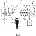
- Fig. 1 shows an industrial machine 10.
- the industrial machine 10 is adapted for slicing a work product 11.
- the industrial machine 10 comprises a first conveyor 12 that is actuated by a first motor 14.
- the work product 11 is placed onto the first conveyor 12 by a feeder 16.
- the feeder 16 is operated by a linear motor 18.
- the first conveyor 12 transports the work product 11 towards a cutter 20, wherein the cutter 20 is actuated by a second motor 22.
- the second conveyor 24 comprises a weight sensor 26 for determining the mass of the sliced work product 11.
- the second conveyor 24 then transports the sliced work product 11 to a packaging machine (not shown).
- the motors 14, 18, 22 and the weight sensor 26 are operated by a first, second, third and fourth field device 28a, 28b, 28c, 28d.
- a respective field device 28 is connected to the motors 14, 18, 22 and the sensor 26 via electrical cables 30.
- the field devices 28 are controlled by a PLC (programmable logic controller) 32, wherein the PLC 32 is in connection with the field devices 28 by means of a digital communication bus 34 (i.e. a data network).
- the digital communication bus 34 can be a field bus, e.g. a SERCOS III bus.
- the digital bus 34 can e.g. be used to perform a discovery process to detect machine components connected to the digital bus 34.
- the industrial machine 10 can further comprise a power supply 36 which supplies the field devices 28, the PLC 32, the motors 14, 18, 22 and the sensor 26, etc. with electrical energy.
- the power supply 36 and all entities mentioned to be supplied by the power supply 36 can be considered machine components of the industrial machine 10. Also, all entities necessary for the industrial machine 10 (e.g. carriers, cables, doors, conveyors, etc.) can be considered machine components of the industrial machine 10.
- the industrial machine 10 and in particular the PLC 32 can be connected to an assistant system 38 via a data connection 39.
- the assistant system 38 can also (at least partly) be included or integrated in the PLC 32.
- the assistant system 38 comprises three cameras 40 wherein one camera 40 is carried by a worker 42.
- the field of view of the cameras 40 comprises a view of the industrial machine 10 from different angles, wherein the camera 40 carried by the worker 42 is arranged such that the camera 40 can see what the worker 42 is performing with his hands.
- the images captured by the cameras 40 are transmitted electronically to the assistant system 38.
- the worker 42 can be tasked to attach the first motor 14 at the first conveyor 12. This task is monitored by the cameras 40 and checked for correctness by the assistant system 38, as will be described in more detail later.
- electrical cables 30 of the first motor 14 have to be connected to I/O-ports of the field devices 28.
- the worker 42 can arrange the cables 30 in cable channels 31.
- FIG. 2 An example of a cable channel 31 and a terminal panel 44 is shown in Fig. 2 .
- the terminal panel 44 is arranged adjacent the cable channel 31.
- the terminal panel 44 is electrically connected to I/O-ports of the field devices 28.
- the terminal panel 44 comprises a plurality of electrical terminals 46 wherein the electrical cables 30 are connected to the electrical terminal 46.
- each of the electrical cables 30 can comprise near its end an identification plate 48 that indicates to which actor or sensor the electrical cable 30 is connected.
- the terminal panel 44 comprises identification plates 48 that allow identifying which electrical terminal 46 belongs to which I/O-port of which field device 28.
- the camera 40 carried by the worker 42 can e.g. see a type plate (not shown) of the first motor 14 and thus can identify the type of the first motor 14.
- the position and orientation in which the first motor 14 has been attached can be detected by the cameras 40. If the worker then connects the cables 30 of the first motor 14 into electrical terminals 46 of the terminal panel 44, the cameras 40 can again identify (e.g. via the identification plates 48) to which electrical terminals 46 the worker 42 has connected the cables 30 of the first motor 14. This is performed by the assistant system 38.
- the assistant system 38 identifies the state of the first motor 14, wherein the identified state of the first motor 14 comprises the actual type of the first motor 14, the position and orientation of the first motor 14 and the electrical connections (i.e. the electrical terminals 46) of the first motor 14.
- the assistant system 38 compares the identified state of the first motor 14 to an expected state, wherein the expected state is taken from a digital plan of the industrial machine 10. It is then e.g. detected that the first motor 14 was erroneously not connected to the first conveyor 12 but to the cutter 20, instead.
- the assistant system 38 can then inform the PLC 32 accordingly, wherein the assistant system 38 modifies a machine application running on the PLC 32 in order to reroute command signals such that the command signals for the cutter are then transmitted to the first motor 14 (e.g. by re-mapping network addresses, as described above).
- the worker 42 could e.g. erroneously connect the electrical cables 30 of the first motor 14 to the "wrong" electrical terminals 46.
- This can also be detected via image recognition (e.g. using a neural network).
- image recognition e.g. using a neural network.
- the assistant system 38 modifies the machine application running in the PLC 32 such that electrical signal descant for the first motor 14 are outputted at the electrical terminals 46 at which the first motor 14 is actually connected.
- the assistant system 38 can rectify deviations during the building process of the industrial machine 10 thus ensuring a reliable operation of the complete industrial machine 10.
- the modifications of the machine application can preferably be performed automatically, e.g. after prompting the worker 42 for authorization.
Landscapes
- Engineering & Computer Science (AREA)
- Automation & Control Theory (AREA)
- Physics & Mathematics (AREA)
- General Physics & Mathematics (AREA)
- Computer Networks & Wireless Communication (AREA)
- Signal Processing (AREA)
- Robotics (AREA)
- Mechanical Engineering (AREA)
- Automatic Assembly (AREA)
Priority Applications (1)
| Application Number | Priority Date | Filing Date | Title |
|---|---|---|---|
| EP18187125.2A EP3603902B1 (de) | 2018-08-02 | 2018-08-02 | Verfahren zur konstruktion und/oder wartung einer industriellen maschine |
Applications Claiming Priority (1)
| Application Number | Priority Date | Filing Date | Title |
|---|---|---|---|
| EP18187125.2A EP3603902B1 (de) | 2018-08-02 | 2018-08-02 | Verfahren zur konstruktion und/oder wartung einer industriellen maschine |
Publications (2)
| Publication Number | Publication Date |
|---|---|
| EP3603902A1 true EP3603902A1 (de) | 2020-02-05 |
| EP3603902B1 EP3603902B1 (de) | 2023-06-28 |
Family
ID=63293931
Family Applications (1)
| Application Number | Title | Priority Date | Filing Date |
|---|---|---|---|
| EP18187125.2A Active EP3603902B1 (de) | 2018-08-02 | 2018-08-02 | Verfahren zur konstruktion und/oder wartung einer industriellen maschine |
Country Status (1)
| Country | Link |
|---|---|
| EP (1) | EP3603902B1 (de) |
Cited By (2)
| Publication number | Priority date | Publication date | Assignee | Title |
|---|---|---|---|---|
| US20210278819A1 (en) * | 2020-03-03 | 2021-09-09 | Atlas Copco Ias Uk Limited | Riveting machine |
| EP3974922A1 (de) * | 2020-09-25 | 2022-03-30 | ISHIDA CO., Ltd. | Verpackungsvorrichtung |
Citations (5)
| Publication number | Priority date | Publication date | Assignee | Title |
|---|---|---|---|---|
| US20090110289A1 (en) * | 2007-10-31 | 2009-04-30 | The Boeing Company | Image processing of apparatus condition |
| US20140183254A1 (en) * | 2012-12-27 | 2014-07-03 | Aung HTAY | Method and apparatus for configuring and validating telecom and datacom systems |
| US20160299496A1 (en) * | 2015-04-07 | 2016-10-13 | Rockwell Automation Technologies, Inc. | Portable human-machine interface device |
| EP3229175A1 (de) * | 2016-04-08 | 2017-10-11 | Abb Ag | Computersystem und verfahren zur erzeugung von eingabedaten zur gebäudeautomationskonfiguration aus schrankbildern |
| US20170357233A1 (en) * | 2016-06-08 | 2017-12-14 | Exxonmobil Research And Engineering Company | Automatic visual and acoustic analytics for event detection |
Family Cites Families (1)
| Publication number | Priority date | Publication date | Assignee | Title |
|---|---|---|---|---|
| US9489832B2 (en) * | 2014-04-04 | 2016-11-08 | Rockwell Automation Technologies, Inc. | Industrial-enabled mobile device |
-
2018
- 2018-08-02 EP EP18187125.2A patent/EP3603902B1/de active Active
Patent Citations (5)
| Publication number | Priority date | Publication date | Assignee | Title |
|---|---|---|---|---|
| US20090110289A1 (en) * | 2007-10-31 | 2009-04-30 | The Boeing Company | Image processing of apparatus condition |
| US20140183254A1 (en) * | 2012-12-27 | 2014-07-03 | Aung HTAY | Method and apparatus for configuring and validating telecom and datacom systems |
| US20160299496A1 (en) * | 2015-04-07 | 2016-10-13 | Rockwell Automation Technologies, Inc. | Portable human-machine interface device |
| EP3229175A1 (de) * | 2016-04-08 | 2017-10-11 | Abb Ag | Computersystem und verfahren zur erzeugung von eingabedaten zur gebäudeautomationskonfiguration aus schrankbildern |
| US20170357233A1 (en) * | 2016-06-08 | 2017-12-14 | Exxonmobil Research And Engineering Company | Automatic visual and acoustic analytics for event detection |
Cited By (6)
| Publication number | Priority date | Publication date | Assignee | Title |
|---|---|---|---|---|
| US20210278819A1 (en) * | 2020-03-03 | 2021-09-09 | Atlas Copco Ias Uk Limited | Riveting machine |
| JP2022047472A (ja) * | 2020-03-03 | 2022-03-24 | アトラス コプコ アイエーエス ユーケー リミテッド | リベット機械 |
| EP3974922A1 (de) * | 2020-09-25 | 2022-03-30 | ISHIDA CO., Ltd. | Verpackungsvorrichtung |
| JP2022053977A (ja) * | 2020-09-25 | 2022-04-06 | 株式会社イシダ | 包装装置 |
| AU2021232708B2 (en) * | 2020-09-25 | 2023-05-18 | Ishida Co., Ltd. | Packaging apparatus |
| JP7591807B2 (ja) | 2020-09-25 | 2024-11-29 | 株式会社イシダ | 包装装置 |
Also Published As
| Publication number | Publication date |
|---|---|
| EP3603902B1 (de) | 2023-06-28 |
Similar Documents
| Publication | Publication Date | Title |
|---|---|---|
| KR102339932B1 (ko) | 유연 생산 공정 시스템 | |
| EP3803772B1 (de) | Mobile fahrzeuge in der herstellung | |
| US20240346641A1 (en) | Video confirmation computer | |
| US11794349B2 (en) | System and method of integrating robot into warehouse management software | |
| EP4155854A1 (de) | Automatisierte überwachung mittels bildanalyse | |
| US20200074126A1 (en) | Device and method for controlling a material flow at a material flow nod point | |
| AU2019387205B2 (en) | Method and system for controlling the material flow of objects in a conveyor system of a real warehouse | |
| US20170075346A1 (en) | Work process management system and tag type individual controller used therein | |
| KR20200054065A (ko) | 스마트 러닝 팩토리 시스템 | |
| EP3603902B1 (de) | Verfahren zur konstruktion und/oder wartung einer industriellen maschine | |
| US12063745B2 (en) | Method for processing substrates, in particular wafers, masks or flat panel displays, with a semi-conductor industry machine | |
| CN110414283A (zh) | 卷烟生产一号工程标签条码识别装置 | |
| EP4339856A1 (de) | Systeme und verfahren zur dynamischen aktualisierung maschinenlesbarer markierungen für industrielle automatisierungskomponenten | |
| EP3751486A1 (de) | Vorrichtung und verfahren zur elektronischen etikettenverwaltung | |
| Schoepflin et al. | Smart material delivery unit for the production supplying logistics of aircraft | |
| US20250245994A1 (en) | Workstation system for automated inspection of robotically or manually performed dexterous tasks | |
| CN119882547A (zh) | 一种用于pcb传输的接驳传送控制方法及接驳传送控制系统 | |
| US11262716B2 (en) | Method for the parameterization of a sensor | |
| US20240311990A1 (en) | Method and system for detecting a configuration of a modular safety controller | |
| CN111580088B (zh) | 具有通信接口的雷达传感器 | |
| US20250264859A1 (en) | Systems and methods for industrial systems diagnostics using mobile device imaging | |
| EP4687076A1 (de) | Autonome rekalibrierung eines ml-basierten werkzeugs in einer industriellen umgebung | |
| Moon et al. | Software-defined self-learning control system for industrial robots by using reinforcement learning | |
| US12455248B1 (en) | Packaging line monitoring systems and methods | |
| Queirós | LiDAR-based pallet condition evaluation in automated Storage and Retrieval Machines |
Legal Events
| Date | Code | Title | Description |
|---|---|---|---|
| PUAI | Public reference made under article 153(3) epc to a published international application that has entered the european phase |
Free format text: ORIGINAL CODE: 0009012 |
|
| STAA | Information on the status of an ep patent application or granted ep patent |
Free format text: STATUS: THE APPLICATION HAS BEEN PUBLISHED |
|
| AK | Designated contracting states |
Kind code of ref document: A1 Designated state(s): AL AT BE BG CH CY CZ DE DK EE ES FI FR GB GR HR HU IE IS IT LI LT LU LV MC MK MT NL NO PL PT RO RS SE SI SK SM TR |
|
| AX | Request for extension of the european patent |
Extension state: BA ME |
|
| STAA | Information on the status of an ep patent application or granted ep patent |
Free format text: STATUS: REQUEST FOR EXAMINATION WAS MADE |
|
| 17P | Request for examination filed |
Effective date: 20200804 |
|
| RBV | Designated contracting states (corrected) |
Designated state(s): AL AT BE BG CH CY CZ DE DK EE ES FI FR GB GR HR HU IE IS IT LI LT LU LV MC MK MT NL NO PL PT RO RS SE SI SK SM TR |
|
| STAA | Information on the status of an ep patent application or granted ep patent |
Free format text: STATUS: EXAMINATION IS IN PROGRESS |
|
| 17Q | First examination report despatched |
Effective date: 20210323 |
|
| GRAP | Despatch of communication of intention to grant a patent |
Free format text: ORIGINAL CODE: EPIDOSNIGR1 |
|
| STAA | Information on the status of an ep patent application or granted ep patent |
Free format text: STATUS: GRANT OF PATENT IS INTENDED |
|
| RIC1 | Information provided on ipc code assigned before grant |
Ipc: G06F 3/01 20060101ALN20221220BHEP Ipc: G05B 19/05 20060101ALI20221220BHEP Ipc: G05B 23/02 20060101ALI20221220BHEP Ipc: G05B 19/042 20060101ALI20221220BHEP Ipc: B25J 9/16 20060101AFI20221220BHEP |
|
| INTG | Intention to grant announced |
Effective date: 20230116 |
|
| GRAS | Grant fee paid |
Free format text: ORIGINAL CODE: EPIDOSNIGR3 |
|
| GRAA | (expected) grant |
Free format text: ORIGINAL CODE: 0009210 |
|
| STAA | Information on the status of an ep patent application or granted ep patent |
Free format text: STATUS: THE PATENT HAS BEEN GRANTED |
|
| AK | Designated contracting states |
Kind code of ref document: B1 Designated state(s): AL AT BE BG CH CY CZ DE DK EE ES FI FR GB GR HR HU IE IS IT LI LT LU LV MC MK MT NL NO PL PT RO RS SE SI SK SM TR |
|
| REG | Reference to a national code |
Ref country code: CH Ref legal event code: EP |
|
| REG | Reference to a national code |
Ref country code: AT Ref legal event code: REF Ref document number: 1582295 Country of ref document: AT Kind code of ref document: T Effective date: 20230715 |
|
| REG | Reference to a national code |
Ref country code: IE Ref legal event code: FG4D |
|
| REG | Reference to a national code |
Ref country code: DE Ref legal event code: R096 Ref document number: 602018052347 Country of ref document: DE |
|
| REG | Reference to a national code |
Ref country code: LT Ref legal event code: MG9D |
|
| PG25 | Lapsed in a contracting state [announced via postgrant information from national office to epo] |
Ref country code: SE Free format text: LAPSE BECAUSE OF FAILURE TO SUBMIT A TRANSLATION OF THE DESCRIPTION OR TO PAY THE FEE WITHIN THE PRESCRIBED TIME-LIMIT Effective date: 20230628 Ref country code: NO Free format text: LAPSE BECAUSE OF FAILURE TO SUBMIT A TRANSLATION OF THE DESCRIPTION OR TO PAY THE FEE WITHIN THE PRESCRIBED TIME-LIMIT Effective date: 20230928 |
|
| REG | Reference to a national code |
Ref country code: NL Ref legal event code: MP Effective date: 20230628 |
|
| REG | Reference to a national code |
Ref country code: AT Ref legal event code: MK05 Ref document number: 1582295 Country of ref document: AT Kind code of ref document: T Effective date: 20230628 |
|
| PG25 | Lapsed in a contracting state [announced via postgrant information from national office to epo] |
Ref country code: RS Free format text: LAPSE BECAUSE OF FAILURE TO SUBMIT A TRANSLATION OF THE DESCRIPTION OR TO PAY THE FEE WITHIN THE PRESCRIBED TIME-LIMIT Effective date: 20230628 Ref country code: NL Free format text: LAPSE BECAUSE OF FAILURE TO SUBMIT A TRANSLATION OF THE DESCRIPTION OR TO PAY THE FEE WITHIN THE PRESCRIBED TIME-LIMIT Effective date: 20230628 Ref country code: LV Free format text: LAPSE BECAUSE OF FAILURE TO SUBMIT A TRANSLATION OF THE DESCRIPTION OR TO PAY THE FEE WITHIN THE PRESCRIBED TIME-LIMIT Effective date: 20230628 Ref country code: LT Free format text: LAPSE BECAUSE OF FAILURE TO SUBMIT A TRANSLATION OF THE DESCRIPTION OR TO PAY THE FEE WITHIN THE PRESCRIBED TIME-LIMIT Effective date: 20230628 Ref country code: HR Free format text: LAPSE BECAUSE OF FAILURE TO SUBMIT A TRANSLATION OF THE DESCRIPTION OR TO PAY THE FEE WITHIN THE PRESCRIBED TIME-LIMIT Effective date: 20230628 Ref country code: GR Free format text: LAPSE BECAUSE OF FAILURE TO SUBMIT A TRANSLATION OF THE DESCRIPTION OR TO PAY THE FEE WITHIN THE PRESCRIBED TIME-LIMIT Effective date: 20230929 |
|
| PG25 | Lapsed in a contracting state [announced via postgrant information from national office to epo] |
Ref country code: FI Free format text: LAPSE BECAUSE OF FAILURE TO SUBMIT A TRANSLATION OF THE DESCRIPTION OR TO PAY THE FEE WITHIN THE PRESCRIBED TIME-LIMIT Effective date: 20230628 |
|
| PG25 | Lapsed in a contracting state [announced via postgrant information from national office to epo] |
Ref country code: SK Free format text: LAPSE BECAUSE OF FAILURE TO SUBMIT A TRANSLATION OF THE DESCRIPTION OR TO PAY THE FEE WITHIN THE PRESCRIBED TIME-LIMIT Effective date: 20230628 |
|
| PG25 | Lapsed in a contracting state [announced via postgrant information from national office to epo] |
Ref country code: ES Free format text: LAPSE BECAUSE OF FAILURE TO SUBMIT A TRANSLATION OF THE DESCRIPTION OR TO PAY THE FEE WITHIN THE PRESCRIBED TIME-LIMIT Effective date: 20230628 |
|
| PG25 | Lapsed in a contracting state [announced via postgrant information from national office to epo] |
Ref country code: IS Free format text: LAPSE BECAUSE OF FAILURE TO SUBMIT A TRANSLATION OF THE DESCRIPTION OR TO PAY THE FEE WITHIN THE PRESCRIBED TIME-LIMIT Effective date: 20231028 |
|
| PG25 | Lapsed in a contracting state [announced via postgrant information from national office to epo] |
Ref country code: SM Free format text: LAPSE BECAUSE OF FAILURE TO SUBMIT A TRANSLATION OF THE DESCRIPTION OR TO PAY THE FEE WITHIN THE PRESCRIBED TIME-LIMIT Effective date: 20230628 Ref country code: SK Free format text: LAPSE BECAUSE OF FAILURE TO SUBMIT A TRANSLATION OF THE DESCRIPTION OR TO PAY THE FEE WITHIN THE PRESCRIBED TIME-LIMIT Effective date: 20230628 Ref country code: RO Free format text: LAPSE BECAUSE OF FAILURE TO SUBMIT A TRANSLATION OF THE DESCRIPTION OR TO PAY THE FEE WITHIN THE PRESCRIBED TIME-LIMIT Effective date: 20230628 Ref country code: PT Free format text: LAPSE BECAUSE OF FAILURE TO SUBMIT A TRANSLATION OF THE DESCRIPTION OR TO PAY THE FEE WITHIN THE PRESCRIBED TIME-LIMIT Effective date: 20231030 Ref country code: IS Free format text: LAPSE BECAUSE OF FAILURE TO SUBMIT A TRANSLATION OF THE DESCRIPTION OR TO PAY THE FEE WITHIN THE PRESCRIBED TIME-LIMIT Effective date: 20231028 Ref country code: ES Free format text: LAPSE BECAUSE OF FAILURE TO SUBMIT A TRANSLATION OF THE DESCRIPTION OR TO PAY THE FEE WITHIN THE PRESCRIBED TIME-LIMIT Effective date: 20230628 Ref country code: EE Free format text: LAPSE BECAUSE OF FAILURE TO SUBMIT A TRANSLATION OF THE DESCRIPTION OR TO PAY THE FEE WITHIN THE PRESCRIBED TIME-LIMIT Effective date: 20230628 Ref country code: CZ Free format text: LAPSE BECAUSE OF FAILURE TO SUBMIT A TRANSLATION OF THE DESCRIPTION OR TO PAY THE FEE WITHIN THE PRESCRIBED TIME-LIMIT Effective date: 20230628 Ref country code: AT Free format text: LAPSE BECAUSE OF FAILURE TO SUBMIT A TRANSLATION OF THE DESCRIPTION OR TO PAY THE FEE WITHIN THE PRESCRIBED TIME-LIMIT Effective date: 20230628 |
|
| PG25 | Lapsed in a contracting state [announced via postgrant information from national office to epo] |
Ref country code: PL Free format text: LAPSE BECAUSE OF FAILURE TO SUBMIT A TRANSLATION OF THE DESCRIPTION OR TO PAY THE FEE WITHIN THE PRESCRIBED TIME-LIMIT Effective date: 20230628 |
|
| PG25 | Lapsed in a contracting state [announced via postgrant information from national office to epo] |
Ref country code: MC Free format text: LAPSE BECAUSE OF FAILURE TO SUBMIT A TRANSLATION OF THE DESCRIPTION OR TO PAY THE FEE WITHIN THE PRESCRIBED TIME-LIMIT Effective date: 20230628 |
|
| REG | Reference to a national code |
Ref country code: CH Ref legal event code: PL |
|
| PG25 | Lapsed in a contracting state [announced via postgrant information from national office to epo] |
Ref country code: MC Free format text: LAPSE BECAUSE OF FAILURE TO SUBMIT A TRANSLATION OF THE DESCRIPTION OR TO PAY THE FEE WITHIN THE PRESCRIBED TIME-LIMIT Effective date: 20230628 |
|
| REG | Reference to a national code |
Ref country code: DE Ref legal event code: R097 Ref document number: 602018052347 Country of ref document: DE |
|
| PG25 | Lapsed in a contracting state [announced via postgrant information from national office to epo] |
Ref country code: LU Free format text: LAPSE BECAUSE OF NON-PAYMENT OF DUE FEES Effective date: 20230802 |
|
| PG25 | Lapsed in a contracting state [announced via postgrant information from national office to epo] |
Ref country code: LU Free format text: LAPSE BECAUSE OF NON-PAYMENT OF DUE FEES Effective date: 20230802 Ref country code: DK Free format text: LAPSE BECAUSE OF FAILURE TO SUBMIT A TRANSLATION OF THE DESCRIPTION OR TO PAY THE FEE WITHIN THE PRESCRIBED TIME-LIMIT Effective date: 20230628 Ref country code: CH Free format text: LAPSE BECAUSE OF NON-PAYMENT OF DUE FEES Effective date: 20230831 |
|
| PLBE | No opposition filed within time limit |
Free format text: ORIGINAL CODE: 0009261 |
|
| STAA | Information on the status of an ep patent application or granted ep patent |
Free format text: STATUS: NO OPPOSITION FILED WITHIN TIME LIMIT |
|
| REG | Reference to a national code |
Ref country code: BE Ref legal event code: MM Effective date: 20230831 |
|
| REG | Reference to a national code |
Ref country code: IE Ref legal event code: MM4A |
|
| GBPC | Gb: european patent ceased through non-payment of renewal fee |
Effective date: 20230928 |
|
| 26N | No opposition filed |
Effective date: 20240402 |
|
| PG25 | Lapsed in a contracting state [announced via postgrant information from national office to epo] |
Ref country code: IE Free format text: LAPSE BECAUSE OF NON-PAYMENT OF DUE FEES Effective date: 20230802 |
|
| PG25 | Lapsed in a contracting state [announced via postgrant information from national office to epo] |
Ref country code: GB Free format text: LAPSE BECAUSE OF NON-PAYMENT OF DUE FEES Effective date: 20230928 |
|
| PG25 | Lapsed in a contracting state [announced via postgrant information from national office to epo] |
Ref country code: IE Free format text: LAPSE BECAUSE OF NON-PAYMENT OF DUE FEES Effective date: 20230802 Ref country code: GB Free format text: LAPSE BECAUSE OF NON-PAYMENT OF DUE FEES Effective date: 20230928 Ref country code: SI Free format text: LAPSE BECAUSE OF FAILURE TO SUBMIT A TRANSLATION OF THE DESCRIPTION OR TO PAY THE FEE WITHIN THE PRESCRIBED TIME-LIMIT Effective date: 20230628 |
|
| PG25 | Lapsed in a contracting state [announced via postgrant information from national office to epo] |
Ref country code: BE Free format text: LAPSE BECAUSE OF NON-PAYMENT OF DUE FEES Effective date: 20230831 |
|
| PG25 | Lapsed in a contracting state [announced via postgrant information from national office to epo] |
Ref country code: BG Free format text: LAPSE BECAUSE OF FAILURE TO SUBMIT A TRANSLATION OF THE DESCRIPTION OR TO PAY THE FEE WITHIN THE PRESCRIBED TIME-LIMIT Effective date: 20230628 |
|
| PG25 | Lapsed in a contracting state [announced via postgrant information from national office to epo] |
Ref country code: BG Free format text: LAPSE BECAUSE OF FAILURE TO SUBMIT A TRANSLATION OF THE DESCRIPTION OR TO PAY THE FEE WITHIN THE PRESCRIBED TIME-LIMIT Effective date: 20230628 |
|
| PG25 | Lapsed in a contracting state [announced via postgrant information from national office to epo] |
Ref country code: CY Free format text: LAPSE BECAUSE OF FAILURE TO SUBMIT A TRANSLATION OF THE DESCRIPTION OR TO PAY THE FEE WITHIN THE PRESCRIBED TIME-LIMIT; INVALID AB INITIO Effective date: 20180802 |
|
| PG25 | Lapsed in a contracting state [announced via postgrant information from national office to epo] |
Ref country code: HU Free format text: LAPSE BECAUSE OF FAILURE TO SUBMIT A TRANSLATION OF THE DESCRIPTION OR TO PAY THE FEE WITHIN THE PRESCRIBED TIME-LIMIT; INVALID AB INITIO Effective date: 20180802 |
|
| PGFP | Annual fee paid to national office [announced via postgrant information from national office to epo] |
Ref country code: IT Payment date: 20250825 Year of fee payment: 8 |
|
| PGFP | Annual fee paid to national office [announced via postgrant information from national office to epo] |
Ref country code: FR Payment date: 20250828 Year of fee payment: 8 |
|
| PG25 | Lapsed in a contracting state [announced via postgrant information from national office to epo] |
Ref country code: TR Free format text: LAPSE BECAUSE OF FAILURE TO SUBMIT A TRANSLATION OF THE DESCRIPTION OR TO PAY THE FEE WITHIN THE PRESCRIBED TIME-LIMIT Effective date: 20230628 |
|
| PGFP | Annual fee paid to national office [announced via postgrant information from national office to epo] |
Ref country code: DE Payment date: 20251029 Year of fee payment: 8 |