EP3603840A1 - Floating block of hub shaping mould and hub shaping mould having same - Google Patents
Floating block of hub shaping mould and hub shaping mould having same Download PDFInfo
- Publication number
- EP3603840A1 EP3603840A1 EP18814315.0A EP18814315A EP3603840A1 EP 3603840 A1 EP3603840 A1 EP 3603840A1 EP 18814315 A EP18814315 A EP 18814315A EP 3603840 A1 EP3603840 A1 EP 3603840A1
- Authority
- EP
- European Patent Office
- Prior art keywords
- block
- driving mechanism
- hub
- inner support
- support member
- Prior art date
- Legal status (The legal status is an assumption and is not a legal conclusion. Google has not performed a legal analysis and makes no representation as to the accuracy of the status listed.)
- Withdrawn
Links
Images



Classifications
-
- B—PERFORMING OPERATIONS; TRANSPORTING
- B21—MECHANICAL METAL-WORKING WITHOUT ESSENTIALLY REMOVING MATERIAL; PUNCHING METAL
- B21J—FORGING; HAMMERING; PRESSING METAL; RIVETING; FORGE FURNACES
- B21J5/00—Methods for forging, hammering, or pressing; Special equipment or accessories therefor
- B21J5/008—Incremental forging
-
- B—PERFORMING OPERATIONS; TRANSPORTING
- B21—MECHANICAL METAL-WORKING WITHOUT ESSENTIALLY REMOVING MATERIAL; PUNCHING METAL
- B21D—WORKING OR PROCESSING OF SHEET METAL OR METAL TUBES, RODS OR PROFILES WITHOUT ESSENTIALLY REMOVING MATERIAL; PUNCHING METAL
- B21D53/00—Making other particular articles
- B21D53/26—Making other particular articles wheels or the like
- B21D53/30—Making other particular articles wheels or the like wheel rims
-
- B—PERFORMING OPERATIONS; TRANSPORTING
- B21—MECHANICAL METAL-WORKING WITHOUT ESSENTIALLY REMOVING MATERIAL; PUNCHING METAL
- B21D—WORKING OR PROCESSING OF SHEET METAL OR METAL TUBES, RODS OR PROFILES WITHOUT ESSENTIALLY REMOVING MATERIAL; PUNCHING METAL
- B21D3/00—Straightening or restoring form of metal rods, metal tubes, metal profiles, or specific articles made therefrom, whether or not in combination with sheet metal parts
- B21D3/14—Recontouring
-
- B—PERFORMING OPERATIONS; TRANSPORTING
- B21—MECHANICAL METAL-WORKING WITHOUT ESSENTIALLY REMOVING MATERIAL; PUNCHING METAL
- B21D—WORKING OR PROCESSING OF SHEET METAL OR METAL TUBES, RODS OR PROFILES WITHOUT ESSENTIALLY REMOVING MATERIAL; PUNCHING METAL
- B21D3/00—Straightening or restoring form of metal rods, metal tubes, metal profiles, or specific articles made therefrom, whether or not in combination with sheet metal parts
- B21D3/16—Straightening or restoring form of metal rods, metal tubes, metal profiles, or specific articles made therefrom, whether or not in combination with sheet metal parts of specific articles made from metal rods, tubes, or profiles, e.g. crankshafts, by specially adapted methods or means
-
- B—PERFORMING OPERATIONS; TRANSPORTING
- B21—MECHANICAL METAL-WORKING WITHOUT ESSENTIALLY REMOVING MATERIAL; PUNCHING METAL
- B21D—WORKING OR PROCESSING OF SHEET METAL OR METAL TUBES, RODS OR PROFILES WITHOUT ESSENTIALLY REMOVING MATERIAL; PUNCHING METAL
- B21D31/00—Other methods for working sheet metal, metal tubes, metal profiles
- B21D31/005—Incremental shaping or bending, e.g. stepwise moving a shaping tool along the surface of the workpiece
-
- B—PERFORMING OPERATIONS; TRANSPORTING
- B21—MECHANICAL METAL-WORKING WITHOUT ESSENTIALLY REMOVING MATERIAL; PUNCHING METAL
- B21K—MAKING FORGED OR PRESSED METAL PRODUCTS, e.g. HORSE-SHOES, RIVETS, BOLTS OR WHEELS
- B21K1/00—Making machine elements
- B21K1/28—Making machine elements wheels; discs
- B21K1/38—Making machine elements wheels; discs rims; tyres
-
- B—PERFORMING OPERATIONS; TRANSPORTING
- B21—MECHANICAL METAL-WORKING WITHOUT ESSENTIALLY REMOVING MATERIAL; PUNCHING METAL
- B21J—FORGING; HAMMERING; PRESSING METAL; RIVETING; FORGE FURNACES
- B21J13/00—Details of machines for forging, pressing, or hammering
- B21J13/02—Dies or mountings therefor
- B21J13/025—Dies with parts moving along auxiliary lateral directions
Definitions
- the present disclosure relates to the technical field of hub shaping, in particular to a floating block of a hub shaping mold and a hub shaping mold having the same.
- hub products In heat treatment, hub products usually have a large deformation.
- the deformation of the hub products can be eliminated in a mechanical cutting mode after the heat treatment to obtain the required size.
- the material consumption of the hub products is greatly increased, the cost is high, and the production efficiency is low.
- the present disclosure provides a floating block of a hub shaping mold and a hub shaping mold thereof.
- the present disclosure provides the floating block of the hub shaping mold.
- the floating block of the hub shaping mold can include: at least one inner support member having a first side and a second side opposite to each other, wherein the first side of the at least one inner support member can include a first arc surface, and at least one first bulge can be arranged on the first arc surface; at least one outer pressing member having a first side and a second side opposite to each other, wherein the first side of the at least one outer pressing member can include a second arc surface matched with the first arc surface, at least one second bulge can be arranged on the second arc surface, and the at least one first bulge and the at least one second bulge can be arranged in a staggered manner.
- the present disclosure further includes a hub shaping mold.
- the hub shaping mold for shaping a hub can include: a third driving mechanism; a first workbench, wherein a rotary disk can be arranged on the first workbench and connected with the third driving mechanism; a first die core, wherein the first die core can be arranged on the rotary disk, a positioning element can be arranged on the first die core, the first die core can be matched with the positioning element to fix a hub to be shaped; the at least one inner support member; a second workbench arranged above the first workbench, wherein a first driving mechanism can be disposed on the second workbench, the first driving mechanism can include an output shaft connected with a pressing block, the at least one inner support member can be connected with the pressing block, and the first driving mechanism can be configured for driving the pressing block to move so as to drive the at least one inner support member to move; a second die core arranged above the first die core, wherein the at least one inner support member can abut against the second die core; and the at least one outer pressing member.
- the present disclosure provides a hub shaping mold 100.
- the hub shaping mold 100 is configured for shaping a hub 101.
- the hub 101 can include a lower surface and an upper surface, which are oppositely arranged.
- the hub 101 can further include an inner wall and an outer wall, which are oppositely arranged.
- the hub shaping mold 100 can include a first workbench 10, a first die core 20, a second die core 30, a second workbench 40, a first driving mechanism 50, at least one inner support member 60, at least one outer pressing member 70, a second driving mechanism 80 and a third driving mechanism 90.
- the first die core 20 and the second die core 30 can be arranged between the first workbench 10 and the second workbench 40.
- the first driving mechanism 50 can be installed on the second workbench 40 and configured for driving the inner support member 60 to move.
- the second driving mechanism 80 can be configured for driving the outer pressing member 70 to move.
- the third driving mechanism 90 can be mounted on the first workbench 10.
- the first workbench 10 can include an upper surface 10a and a lower surface 10b which can be oppositely arranged.
- a rotary disk 11 can be arranged on the upper surface 10a of the first workbench 10.
- a support 12 can be arranged on the lower surface 10b of the first workbench 10.
- the third driving mechanism 90 can be disposed on the support 12 and include a driving shaft 91.
- the driving shaft 91 can penetrate through the first workbench 10 and be fixedly connected with the rotary disk 11.
- the driving shaft 91 can be configured for driving the rotary disk 11 to rotate.
- a bearing 13 can be arranged between the rotary disk 11 and the first workbench 10.
- a speed reducer can be also arranged between the third driving mechanism 90 and the rotary disk 11.
- the third driving mechanism 90 can be a servo motor or a common motor.
- the first die core 20 can be fixed on the rotary disk 11.
- the first die core 20 can include an upper surface and a lower surface which are oppositely arranged.
- the lower surface of the first die core 20 can abut against the rotary disk 11, so that when the rotary disk 11 rotates, the first die core 20 can drive the hub 101 to rotate concentrically.
- the upper surface of the first die core 20 can be matched with the lower surface of the hub 101.
- a positioning element 21 can be arranged on the first die core 20. And the first die core 20 can be matched with the positioning element 21 to position and clamp the hub 101.
- the second die core 30 can be arranged above the first die core 20.
- the inner support member 60 abuts against the second die core 30.
- the second die core 30 can include a lower surface and an upper surface which are oppositely arranged. The lower surface of the second die core 30 can be matched with the upper surface of the hub 101.
- the second workbench 40 can be disposed above the first workbench 10.
- the first driving mechanism 50 can be installed on the second workbench 40.
- a fourth driving mechanism 41 and a die holder 42 can be arranged on the second workbench 40.
- a connecting column 411 can be arranged on the fourth driving mechanism 41.
- the die holder 42 can be sleeved around the connecting column 411.
- the first driving mechanism 50 can be arranged in the die holder 42.
- the fourth driving mechanisms 41 can drive the connecting column 411 to move downwards, which can result in the hub 101 abutting against the first die core 20.
- the fourth driving mechanism 41 can be a plunger cylinder, an oil cylinder, or the like.
- the first driving mechanism 50 can include an output shaft 51.
- the output shaft 51 can be connected with a pressing block 52.
- the inner support member 60 can be connected with the pressing block 52.
- a connecting block 53 can be arranged on the output shaft 51.
- the pressing block 52 can be arranged on the connecting block 53.
- a connecting groove (not shown) can be formed in the pressing block 52.
- the connecting groove can include a first inclined surface (not shown).
- the first driving mechanism 50 can drive the connecting block 53 to make the pressing block 52 move up and down.
- the first inclined surface of the connecting groove can be matched with the inner support member 60, so that a vertical movement of the pressing block 52 driven by the first driving mechanism 50 can be converted into a horizontal movement of the inner support member 60.
- the first driving mechanism 50 can be a servo motor or a common motor.
- the inner support member 60 can be configured for shaping the inner wall of the hub 101.
- the number of the inner support members 60 can be one or more, e.g., the hub shaping mold 100 can include a plurality of inner support members 60.
- Each inner support member 60 can include a first side 60a and an oppositely arranged second side 60b.
- the first side 60a of the inner support member 60 can include a first arc surface 61.
- At least one first bulge 62 can be arranged on the first arc surface 61.
- a circular structure can be formed by the first arc surfaces 61 of the plurality of inner support members 60.
- the first bulge 62 can be a point-shaped protrusion, and a plurality of first bulges 62 can be arranged on the first arc surface 61 in a rectangular array manner.
- Each of the inner support members 60 can include a supporting plate 63 and a pushing block 64.
- the supporting plate 63 can include a first side 63a and a second side 63b opposite to each other.
- the first arc surface 61 can be located on the first side 63a of the supporting plate 63.
- the second side 63b of the supporting plate 63 can be connected with the pushing block 64.
- a cross section of the pushing block 64 can be T-shaped.
- the pushing block 64 can include a first block 641 and a second block 642 connected with each other.
- the first block 641 can be arranged between the supporting plate 63 and the second block 642.
- the first block 641 can be located on the second side 63b of the supporting plate 63 and connected with the supporting plate 63.
- the second block 642 can include a first side 642a and a second side 642b opposite to each other.
- the first side 642a of the second block can be obliquely arranged towards the supporting plate 63 to form a second inclined surface 6421.
- the first inclined surface of the connecting groove and the second inclined surface 6421 can be matched with each other.
- the first driving mechanism 50 can drive the pressing block 52 to move so as to enable the first inclined surface to touch and press the second inclined surface 6421, so that the vertical movement of the first driving mechanism 50 can be converted into the horizontal movement of the inner support member 60, and the inner support member 60 can extrude and shape the hub 101.
- the outer pressing member 70 can be configured for shaping the outer wall of the hub 101.
- the number of the outer pressing members 70 can be one or more, e.g., the hub shaping mold 100 can include a plurality of outer pressing members 70.
- the number of the outer pressing members 70 can be matched with the number of the inner support members 60, that is, the outer pressing members 70 are corresponding to the inner support members 60 by one to one, and each outer pressing member 70 is opposite to the corresponding inner support member 60.
- the first driving mechanism 50 can drive the inner support member 60 to move and the second driving mechanism 80 drives the outer pressing member 70 to move, so that the inner support member 60 and the outer pressing member 70 can be close to each other, tightly pressed and attached to the inner wall and the outer wall of the hub 101.
- the first arc surface 61 of the inner support member 60 and the outer pressing member 70 can simultaneously generate a pressure toward the hub 101, so that a contour line can be formed on the hub 101 and the hub 101 can be shaped to a standard hub.
- the plurality of outer pressing members 70 can be formed to an annular structure matched with the circular structure formed by the first arc surfaces 61 of the inner support members 60.
- Each of the outer pressing members 70 can have a first side 70a and a second side 70 opposite to each other.
- the first side 70a of the outer pressing member 70 can include a second arc surface 71 matched with the first arc surface 61.
- At least one second bulge 72 can be arranged on the second arc surface 71, for example, a plurality of second bulges 72 can be arranged on the second arc surface 71.
- the plurality of first bulges 62 and the plurality of second bulges 72 can be arranged in a staggered manner to improve the shaping effect.
- Both the first arc surface 61 and the second arc surface 71 can be circular arc surfaces.
- the hub 101 can be rotated and shaped repeatedly, so that all directions of the hub 101 can be pressed by the first bulges 62 of the first arc surface 61 and the second bulges 72 of the second arc surface 71.
- the hub 101 can be shaped to be in a round shape and a standard size.
- the second bulges 72 can be in a point shape.
- the outer pressing member 70 can be regarded as a point-like outer pressing member.
- the plurality of second bulges 72 and the plurality of first bulges 62 can be arranged in a staggered manner.
- each of the outer pressing members 70 can include a pressing plate 73 and a fixing block 74.
- the pressing plate 73 can include a first side 73a and a second side 73b opposite to each other.
- the second arc surface 71 can be located on the first side 73a of the pressing plate 73.
- the pressing plate 73 can further include a first end 73c and a second end 71d opposite to each other, and both the first end 73c and the second end 71d of the pressing plate can be connected with the fixing block 74.
- the number of the fixing blocks 74 can be one or more. Each of the fixing blocks 74 can be in a U shape. An opening 741 can be formed in each fixing block 74 and away from the pressing plate 73.
- the fixing block 74 can be connected with the second driving mechanism 80.
- the pressing plate 73 can be driven to move by the second driving mechanism 80.
- the number of the fixing blocks is four, and the four fixing blocks 74 are distributed on four corners of the outer pressing member 70, so that the outer pressing member 70 will not rotate, or move up and down in a moving process and dislocation can be avoided.
- the second bulges 72 can be arranged on the second arc surface 71 in a rectangular array manner.
- the second bulges 72 in each row can be in a staggered arrangement with the first bulges 62 in each row on the first arc surface 61, such that the first bulges 62 can abut against the second arc surface 71 while the second bulges 72 abut against the first arc surface 61. Therefore, when the inner support member 60 and the outer pressing member 70 clamp the hub 101, the first bulges 62 will abut against the inner wall of the hub 101 and the second bulges 72 will abut against the outer wall of the hub 101. In this way, a good clamping effect can be achieved through the staggered arrangement, and the shaping effect can be improved.
- the second bulge 72 can be tooth-shaped protrusions.
- the outer pressing member 70 can be also regarded as a toothed outer pressing member.
- the tooth-shaped protrusions can be arranged along a circumferential direction of the second arc surface 71.
- the second bulges 72 in each row can be in staggered arrangement with the first bulges 62 in each row, such that the tooth-shaped protrusions can abut against the first arc surface 61 and the first bulges 62 can also abut against the second arc surface 71.
- the outer pressing member 70 can be in a semi-annulus shape.
- a plurality of bolt holes 75 can be formed in the outer pressing member 70 and configured for connecting the outer pressing member 70 with the second driving mechanism 80.
- the number of the bolt holes 75 can be four.
- the four bolt holes 75 can be distributed on four corners of the outer pressing member 70, so that the outer pressing member 70 will not rotate or move up and down in the moving process and dislocation can be avoided.
- the number of the outer pressing members 70 can be two.
- the two outer pressing members 70 can form the annular structure.
- the second driving mechanism 80 can be a servo motor or a common motor.
- the present disclosure further provides a hub shaping method.
- the hub shaping method can be taken by the hub shaping mold 100.
- the hub shaping mold 100 can include the rotating disk 11, the first die core 20, the positioning element 21, the inner support member 60, the first driving mechanism 50, the outer pressing member 70, the second driving mechanism 80 and the like.
- the hub shaping method can include the following steps.
- step S1 of disposing the hub 101 on the rotary disk 11 of the hub shaping mold 100, and positioning and clamping the hub 101 an angle of the hub 101 can be adjusted, and the hub 101 can be positioned and clamped by the first die core 20 and the positioning element 21.
- the step S4 of resetting the inner support member 60 and the outer pressing member 70 can include the following steps: Step S41, rotating the rotary disk 11 in order to make the hub 101 rotate and repeating the steps S1 to S3, until both the inner wall and the outer wall of the hub 101 are shaped by the inner support member 60 and the outer pressing member 70.
- the step S5 of detecting the shape and size of the shaped hub can include the following steps: Step S51, detecting the shape and the size of the shaped hub 101, and adjusting the angle of the hub 101, such that a part of the hub 101 to be shaped (e.g. a recessed or bumped part) can be arranged between the inner support member 60 and the outer pressing member 70 as far as possible.
- Step S51 detecting the shape and the size of the shaped hub 101
- adjusting the angle of the hub 101 such that a part of the hub 101 to be shaped (e.g. a recessed or bumped part) can be arranged between the inner support member 60 and the outer pressing member 70 as far as possible.
- the hub shaping method By the hub shaping method, a utilization rate of materials of the hub products can be reduced by 1 kg - 3kg, an overall cost can be reduced by 10%-20%, and the productivity can be greatly improved. That is, the shaping mold has a great advantage on shaping the hub.
- steps in the flow chart of FIG. 12 can be displayed in sequence according to the indication of the arrows, the steps may not be necessarily sequentially performed in the order indicated by the arrows. Unless explicitly stated herein, the execution of these steps may not be strictly limited in order, but may be performed in other sequences. Further, at least one of the steps in FIG. 12 may include a plurality of sub-steps or stages, which may not be necessarily performed at the same time, but can be executed at different times. The execution sequence may not be necessarily performed in sequence, and at least a part of the sub-steps or phases of other steps or other steps can be executed in turn or alternatively.
Landscapes
- Engineering & Computer Science (AREA)
- Mechanical Engineering (AREA)
- Manufacture Of Motors, Generators (AREA)
- Mounting, Exchange, And Manufacturing Of Dies (AREA)
- Connection Of Motors, Electrical Generators, Mechanical Devices, And The Like (AREA)
- Moulds For Moulding Plastics Or The Like (AREA)
- Packaging Of Annular Or Rod-Shaped Articles, Wearing Apparel, Cassettes, Or The Like (AREA)
Abstract
Description
- This application claims all benefits from China Patent Application Nos.
201710427988.3, filed on June 8, 2017 201710428634.0, filed on June 8, 2017 201710429158.4, filed on June 8, 2017 201710429167.3, filed on June 8, 2017 201720661585.0, filed on June 8, 2017 201720661592.0, filed on June 8, 2017 201720662122.6, filed on June 8, 2017 - The present disclosure relates to the technical field of hub shaping, in particular to a floating block of a hub shaping mold and a hub shaping mold having the same.
- In heat treatment, hub products usually have a large deformation. The deformation of the hub products can be eliminated in a mechanical cutting mode after the heat treatment to obtain the required size. However, the material consumption of the hub products is greatly increased, the cost is high, and the production efficiency is low.
- The present disclosure provides a floating block of a hub shaping mold and a hub shaping mold thereof.
- The present disclosure provides the floating block of the hub shaping mold.
- The floating block of the hub shaping mold can include: at least one inner support member having a first side and a second side opposite to each other, wherein the first side of the at least one inner support member can include a first arc surface, and at least one first bulge can be arranged on the first arc surface; at least one outer pressing member having a first side and a second side opposite to each other, wherein the first side of the at least one outer pressing member can include a second arc surface matched with the first arc surface, at least one second bulge can be arranged on the second arc surface, and the at least one first bulge and the at least one second bulge can be arranged in a staggered manner.
- The present disclosure further includes a hub shaping mold.
- The hub shaping mold for shaping a hub can include: a third driving mechanism; a first workbench, wherein a rotary disk can be arranged on the first workbench and connected with the third driving mechanism; a first die core, wherein the first die core can be arranged on the rotary disk, a positioning element can be arranged on the first die core, the first die core can be matched with the positioning element to fix a hub to be shaped; the at least one inner support member; a second workbench arranged above the first workbench, wherein a first driving mechanism can be disposed on the second workbench, the first driving mechanism can include an output shaft connected with a pressing block, the at least one inner support member can be connected with the pressing block, and the first driving mechanism can be configured for driving the pressing block to move so as to drive the at least one inner support member to move; a second die core arranged above the first die core, wherein the at least one inner support member can abut against the second die core; and the at least one outer pressing member.
- The details of one or more embodiments of the present disclosure will be set forth in the accompanying drawings and description. Other features, objects, and advantages of the present disclosure will become apparent from the description, drawings, and claims.
- In order to better describe and illustrate embodiments and/or examples of the present disclosure, one or more drawings are provided. Additional details or examples for describing the drawings should not be considered to be limited by the scope of any of the best modes of the embodiments and/or examples of the present disclosure.
-
FIG. 1 is a perspective view of a hub shaping mold in one embodiment. -
FIG. 2 is a cross-sectional view of a hub shaping mold in one embodiment. -
FIG. 3 is a perspective view of an inner support member in one embodiment. -
FIG. 4 is a top view of an inner support member in one embodiment. -
FIG. 5 is a front view of an inner support member in one embodiment. -
FIG. 6 is a perspective view of an outer pressing member in one embodiment. -
FIG. 7 is a front view of an outer pressing member in one embodiment. -
FIG. 8 is a top view of an outer pressing member in one embodiment. -
FIG. 9 is a perspective view of an outer pressing member in another embodiment. -
FIG. 10 is a front view of an outer pressing member in another embodiment. -
FIG. 11 is a top view of an outer pressing member in another embodiment. -
FIG. 12 is a flow chart of a method for shaping a hub in one embodiment. - The present disclosure will be described in further detail with reference to the accompanying drawings and specific embodiments.
- As shown in
FIG. 1 , the present disclosure provides a hub shaping mold 100. The hub shaping mold 100 is configured for shaping ahub 101. Thehub 101 can include a lower surface and an upper surface, which are oppositely arranged. Thehub 101 can further include an inner wall and an outer wall, which are oppositely arranged. - Referring to
FIG. 2 , the hub shaping mold 100 can include afirst workbench 10, afirst die core 20, a second die core 30, asecond workbench 40, afirst driving mechanism 50, at least oneinner support member 60, at least one outer pressingmember 70, asecond driving mechanism 80 and athird driving mechanism 90. Thefirst die core 20 and the second die core 30 can be arranged between thefirst workbench 10 and thesecond workbench 40. Thefirst driving mechanism 50 can be installed on thesecond workbench 40 and configured for driving theinner support member 60 to move. Thesecond driving mechanism 80 can be configured for driving the outer pressingmember 70 to move. Thethird driving mechanism 90 can be mounted on thefirst workbench 10. - The
first workbench 10 can include anupper surface 10a and alower surface 10b which can be oppositely arranged. Arotary disk 11 can be arranged on theupper surface 10a of thefirst workbench 10. Asupport 12 can be arranged on thelower surface 10b of thefirst workbench 10. Thethird driving mechanism 90 can be disposed on thesupport 12 and include adriving shaft 91. Thedriving shaft 91 can penetrate through thefirst workbench 10 and be fixedly connected with therotary disk 11. Thedriving shaft 91 can be configured for driving therotary disk 11 to rotate. Abearing 13 can be arranged between therotary disk 11 and thefirst workbench 10. And a speed reducer can be also arranged between thethird driving mechanism 90 and therotary disk 11. - In one embodiment, the
third driving mechanism 90 can be a servo motor or a common motor. - The
first die core 20 can be fixed on therotary disk 11. Thefirst die core 20 can include an upper surface and a lower surface which are oppositely arranged. The lower surface of thefirst die core 20 can abut against therotary disk 11, so that when therotary disk 11 rotates, thefirst die core 20 can drive thehub 101 to rotate concentrically. The upper surface of thefirst die core 20 can be matched with the lower surface of thehub 101. A positioning element 21 can be arranged on the first diecore 20. And thefirst die core 20 can be matched with the positioning element 21 to position and clamp thehub 101. - The second die core 30 can be arranged above the
first die core 20. Theinner support member 60 abuts against the second die core 30. The second die core 30 can include a lower surface and an upper surface which are oppositely arranged. The lower surface of the second die core 30 can be matched with the upper surface of thehub 101. - The
second workbench 40 can be disposed above thefirst workbench 10. Thefirst driving mechanism 50 can be installed on thesecond workbench 40. Afourth driving mechanism 41 and a dieholder 42 can be arranged on thesecond workbench 40. A connectingcolumn 411 can be arranged on thefourth driving mechanism 41. Thedie holder 42 can be sleeved around the connectingcolumn 411. In one embodiment, thefirst driving mechanism 50 can be arranged in thedie holder 42. Thefourth driving mechanisms 41 can drive the connectingcolumn 411 to move downwards, which can result in thehub 101 abutting against thefirst die core 20. - In one embodiment, the
fourth driving mechanism 41 can be a plunger cylinder, an oil cylinder, or the like. - The
first driving mechanism 50 can include anoutput shaft 51. Theoutput shaft 51 can be connected with apressing block 52. Theinner support member 60 can be connected with thepressing block 52. A connectingblock 53 can be arranged on theoutput shaft 51. Thepressing block 52 can be arranged on the connectingblock 53. A connecting groove (not shown) can be formed in thepressing block 52. The connecting groove can include a first inclined surface (not shown). - In this embodiment, the
first driving mechanism 50 can drive the connectingblock 53 to make thepressing block 52 move up and down. The first inclined surface of the connecting groove can be matched with theinner support member 60, so that a vertical movement of thepressing block 52 driven by thefirst driving mechanism 50 can be converted into a horizontal movement of theinner support member 60. - In one embodiment, the
first driving mechanism 50 can be a servo motor or a common motor. - Referring to
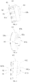
FIGs. 2 to 5 , theinner support member 60 can be configured for shaping the inner wall of thehub 101. The number of theinner support members 60 can be one or more, e.g., the hub shaping mold 100 can include a plurality ofinner support members 60. Eachinner support member 60 can include a first side 60a and an oppositely arrangedsecond side 60b. The first side 60a of theinner support member 60 can include afirst arc surface 61. At least onefirst bulge 62 can be arranged on thefirst arc surface 61. A circular structure can be formed by the first arc surfaces 61 of the plurality ofinner support members 60. In one embodiment, thefirst bulge 62 can be a point-shaped protrusion, and a plurality offirst bulges 62 can be arranged on thefirst arc surface 61 in a rectangular array manner. - Each of the
inner support members 60 can include a supportingplate 63 and a pushingblock 64. The supportingplate 63 can include afirst side 63a and asecond side 63b opposite to each other. Thefirst arc surface 61 can be located on thefirst side 63a of the supportingplate 63. Thesecond side 63b of the supportingplate 63 can be connected with the pushingblock 64. - A cross section of the pushing
block 64 can be T-shaped. The pushingblock 64 can include afirst block 641 and asecond block 642 connected with each other. Thefirst block 641 can be arranged between the supportingplate 63 and thesecond block 642. In one embodiment, thefirst block 641 can be located on thesecond side 63b of the supportingplate 63 and connected with the supportingplate 63. - The
second block 642 can include afirst side 642a and asecond side 642b opposite to each other. Thefirst side 642a of the second block can be obliquely arranged towards the supportingplate 63 to form a secondinclined surface 6421. The first inclined surface of the connecting groove and the secondinclined surface 6421 can be matched with each other. Thefirst driving mechanism 50 can drive thepressing block 52 to move so as to enable the first inclined surface to touch and press the secondinclined surface 6421, so that the vertical movement of thefirst driving mechanism 50 can be converted into the horizontal movement of theinner support member 60, and theinner support member 60 can extrude and shape thehub 101. - Referring to
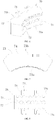
FIG. 2 andFIG. 6 , the outer pressingmember 70 can be configured for shaping the outer wall of thehub 101. The number of the outer pressingmembers 70 can be one or more, e.g., the hub shaping mold 100 can include a plurality of outer pressingmembers 70. The number of the outer pressingmembers 70 can be matched with the number of theinner support members 60, that is, the outer pressingmembers 70 are corresponding to theinner support members 60 by one to one, and each outer pressingmember 70 is opposite to the correspondinginner support member 60. Thefirst driving mechanism 50 can drive theinner support member 60 to move and thesecond driving mechanism 80 drives the outer pressingmember 70 to move, so that theinner support member 60 and the outer pressingmember 70 can be close to each other, tightly pressed and attached to the inner wall and the outer wall of thehub 101. Thefirst arc surface 61 of theinner support member 60 and the outer pressingmember 70 can simultaneously generate a pressure toward thehub 101, so that a contour line can be formed on thehub 101 and thehub 101 can be shaped to a standard hub. - In one embodiment, the plurality of outer pressing
members 70 can be formed to an annular structure matched with the circular structure formed by the first arc surfaces 61 of theinner support members 60. - Each of the outer pressing
members 70 can have afirst side 70a and asecond side 70 opposite to each other. Thefirst side 70a of the outer pressingmember 70 can include asecond arc surface 71 matched with thefirst arc surface 61. At least onesecond bulge 72 can be arranged on thesecond arc surface 71, for example, a plurality ofsecond bulges 72 can be arranged on thesecond arc surface 71. The plurality offirst bulges 62 and the plurality ofsecond bulges 72 can be arranged in a staggered manner to improve the shaping effect. - Both the
first arc surface 61 and thesecond arc surface 71 can be circular arc surfaces. Thehub 101 can be rotated and shaped repeatedly, so that all directions of thehub 101 can be pressed by thefirst bulges 62 of thefirst arc surface 61 and thesecond bulges 72 of thesecond arc surface 71. Thehub 101 can be shaped to be in a round shape and a standard size. - Referring to
FIGs. 6 to 8 , in one embodiment, thesecond bulges 72 can be in a point shape. The outer pressingmember 70 can be regarded as a point-like outer pressing member. The plurality ofsecond bulges 72 and the plurality offirst bulges 62 can be arranged in a staggered manner. - In this embodiment, each of the outer pressing
members 70 can include apressing plate 73 and a fixingblock 74. Thepressing plate 73 can include afirst side 73a and asecond side 73b opposite to each other. Thesecond arc surface 71 can be located on thefirst side 73a of thepressing plate 73. Thepressing plate 73 can further include afirst end 73c and a second end 71d opposite to each other, and both thefirst end 73c and the second end 71d of the pressing plate can be connected with the fixingblock 74. - The number of the fixing blocks 74 can be one or more. Each of the fixing blocks 74 can be in a U shape. An
opening 741 can be formed in each fixingblock 74 and away from thepressing plate 73. The fixingblock 74 can be connected with thesecond driving mechanism 80. Thepressing plate 73 can be driven to move by thesecond driving mechanism 80. In one embodiment, the number of the fixing blocks is four, and the four fixingblocks 74 are distributed on four corners of the outer pressingmember 70, so that the outer pressingmember 70 will not rotate, or move up and down in a moving process and dislocation can be avoided. - In one embodiment, the
second bulges 72 can be arranged on thesecond arc surface 71 in a rectangular array manner. The second bulges 72 in each row can be in a staggered arrangement with thefirst bulges 62 in each row on thefirst arc surface 61, such that thefirst bulges 62 can abut against thesecond arc surface 71 while thesecond bulges 72 abut against thefirst arc surface 61. Therefore, when theinner support member 60 and the outer pressingmember 70 clamp thehub 101, thefirst bulges 62 will abut against the inner wall of thehub 101 and thesecond bulges 72 will abut against the outer wall of thehub 101. In this way, a good clamping effect can be achieved through the staggered arrangement, and the shaping effect can be improved. - Referring to
FIGs. 9 to 11 , in another embodiment, thesecond bulge 72 can be tooth-shaped protrusions. The outer pressingmember 70 can be also regarded as a toothed outer pressing member. The tooth-shaped protrusions can be arranged along a circumferential direction of thesecond arc surface 71. The second bulges 72 in each row can be in staggered arrangement with thefirst bulges 62 in each row, such that the tooth-shaped protrusions can abut against thefirst arc surface 61 and thefirst bulges 62 can also abut against thesecond arc surface 71. Therefore, when theinner support member 60 and the outer pressingmember 70 clamp thehub 101, thefirst bulges 62 will abut against the inner wall of thehub 101 and thesecond bulges 72 will abut against the outer wall of thehub 101. In this way, a good clamping effect can be achieved through the staggered arrangement and the shaping effect can be improved. - In this embodiment, the outer pressing
member 70 can be in a semi-annulus shape. A plurality of bolt holes 75 can be formed in the outer pressingmember 70 and configured for connecting the outer pressingmember 70 with thesecond driving mechanism 80. The number of the bolt holes 75 can be four. The fourbolt holes 75 can be distributed on four corners of the outer pressingmember 70, so that the outer pressingmember 70 will not rotate or move up and down in the moving process and dislocation can be avoided. - In this embodiment, the number of the outer pressing
members 70 can be two. The two outer pressingmembers 70 can form the annular structure. - The
second driving mechanism 80 can be a servo motor or a common motor. - Referring to
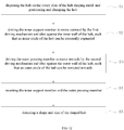
FIG. 12 , the present disclosure further provides a hub shaping method. The hub shaping method can be taken by the hub shaping mold 100. The hub shaping mold 100 can include therotating disk 11, thefirst die core 20, the positioning element 21, theinner support member 60, thefirst driving mechanism 50, the outer pressingmember 70, thesecond driving mechanism 80 and the like. The hub shaping method can include the following steps. - Step S1, disposing the
hub 101 on therotary disk 11 of the hub shaping mold 100, and positioning and clamping thehub 101; - Step S2, driving the
inner support member 60 to move outward by thefirst driving mechanism 50 and abut against the inner wall of thehub 101, such that an inner circle of thehub 101 can be externally expanded; - Step S3, driving the outer pressing
member 70 to move inwards by thesecond driving mechanism 80 and abut against the outer wall of thehub 101, such that an outer circle of thehub 101 can be retracted inwards; - Step S4, resetting the
inner support member 60 and the outer pressingmember 70, that is, separating theinner support member 60 and the outer pressingmember 70 from thehub 101, so that thehub 101 can be freely rotated or taken out; - Step S5, detecting a shape and size of the shaped hub, and determining whether the shape and the size of the shaped hub, if the shape and the size of the shaped hub are up to standard, the shaping ends; if not, the step S1 to the step S4 will be repeated until the shape and the size of the shaped hub are up to standard.
- In the step S1 of disposing the
hub 101 on therotary disk 11 of the hub shaping mold 100, and positioning and clamping thehub 101, an angle of thehub 101 can be adjusted, and thehub 101 can be positioned and clamped by thefirst die core 20 and the positioning element 21. - The step S4 of resetting the
inner support member 60 and the outer pressingmember 70 can include the following steps:
Step S41, rotating therotary disk 11 in order to make thehub 101 rotate and repeating the steps S1 to S3, until both the inner wall and the outer wall of thehub 101 are shaped by theinner support member 60 and the outer pressingmember 70. - The step S5 of detecting the shape and size of the shaped hub can include the following steps:
Step S51, detecting the shape and the size of the shapedhub 101, and adjusting the angle of thehub 101, such that a part of thehub 101 to be shaped (e.g. a recessed or bumped part) can be arranged between theinner support member 60 and the outer pressingmember 70 as far as possible. - By the hub shaping method, a utilization rate of materials of the hub products can be reduced by 1 kg - 3kg, an overall cost can be reduced by 10%-20%, and the productivity can be greatly improved. That is, the shaping mold has a great advantage on shaping the hub.
- It should be understood that although the steps in the flow chart of
FIG. 12 can be displayed in sequence according to the indication of the arrows, the steps may not be necessarily sequentially performed in the order indicated by the arrows. Unless explicitly stated herein, the execution of these steps may not be strictly limited in order, but may be performed in other sequences. Further, at least one of the steps inFIG. 12 may include a plurality of sub-steps or stages, which may not be necessarily performed at the same time, but can be executed at different times. The execution sequence may not be necessarily performed in sequence, and at least a part of the sub-steps or phases of other steps or other steps can be executed in turn or alternatively. - The technical features of the above embodiments can be arbitrarily combined, and all possible combinations of all technical features in the embodiments can be described for simplicity of description. However, as long as the combination of the technical features does not conflict, it should be considered within the scope of the present disclosure.
- The above embodiments only express several embodiments of the present disclosure, and the description can be specific and detailed, but cannot be construed as a limitation on the scope of the present disclosure. It should be noted that many modifications and improvements can be made to persons of ordinary skill in the art without departing from the concept of the present disclosure, and all the materials belong to the protection scope of the present disclosure. Therefore, the protection scope of the present disclosure can be subject to the appended claims.
Claims (15)
- A floating block of a hub shaping mold comprising:at least one inner support member (60) having a first side (60a) and a second side (60b) opposite to each other, wherein the first side (60a) of the at least one inner support member (60) comprises a first arc surface (61), and at least one first bulge (62) is arranged on the first arc surface (61);at least one outer pressing member (70) having a first side (70a) and a second side (70b) opposite to each other, wherein the first side (70a) of the at least one outer pressing member (70) comprises a second arc surface (71) matched with the first arc surface (61), at least one second bulge (72) is arranged on the second arc surface (71), and the at least one first bulge (62) and the at least one second bulge (72) are arranged in a staggered manner.
- The floating block of the hub shaping mold of claim 1, further comprising a first driving mechanism (50) and a second driving mechanism (80), the first driving mechanism (50) is connected with the at least one inner support member (60), the second driving mechanism (80) is connected with the at least one outer pressing member (70), the first driving mechanism (50) and the second driving mechanism (80) are configured for fitting the at least one inner support member (60) and the at least one outer pressing member (70) or separating the at least one inner support member (60) from the at least one pressing member (70).
- The floating block of the hub shaping mold of claim 1, wherein the at least one inner support member (60) comprises a supporting plate (63) and a pushing block (64), the supporting plate (63) has a first side (63a) and a second side (63b) opposite to each other, the first arc surface (61) is located on the first side (63a) of the supporting plate (63a), and the second side (63b) of the supporting plate (63) is connected with the pushing block (64).
- The floating block of the hub shaping mold of claim 3, wherein a cross section of the pushing block (64) is T-shaped, the pushing block (64) comprises a first block (641) and a second block (642) connected with the first block (641), and
the first block (641) is located between the second block (642) and the supporting plate (63) and respectively connected with the second block (642) and the supporting plate (63). - The floating block of the hub shaping mold of claim 4, wherein the second block (642) has a first side (642a) and a second side (642b) arranged opposite to each other, and the first side (642a) of the second block (642) is obliquely arranged towards the supporting plate (63).
- The floating block of the hub shaping mold of claim 3, further comprising a plurality of inner support members (60), and the plurality of inner support members (60) comprise a plurality of first arc surfaces (61) which are encircled to form a circular structure.
- The floating block of the hub shaping mold of claim 6, further comprising a plurality of outer pressing members (70), the plurality of outer pressing members (70) are encircled to form an annular structure matched with the circular structure.
- The floating block of the hub shaping mold of claim 1, wherein the outer pressing member (70) comprises a pressing plate (73) and a fixing block (74),
wherein the pressing plate (73) comprises a first side (73a) and a second side (73b) opposite to each other, the second arc surface (71) is located on the first side (73a) of the pressing plate (73), the pressing plate (73) is provided with a first end (73c) and a second end (73d) opposite to each other, and both the first end (72c) and the second end (73d) of the pressing plate (73) are connected with the fixing block (74). - The floating block of the hub shaping mold of claim 1, wherein the at least one second bulge (72) is point-shaped or tooth-shaped, and the at least one first bulge (62) is arranged in the staggered manner with the at least one point-shaped or tooth-shaped second bulge (72).
- A hub shaping mold for shaping a hub, comprising:a third driving mechanism (90);a first workbench (10), a rotary disk (11) arranged on the first workbench (10) and connected with the third driving mechanism (90);a first die core (20) arranged on the rotary disk (11), a positioning element (21) arranged on the first die core (20), wherein the first die core (20) is matched with the positioning element (21) to fix a hub to be shaped;the at least one inner support member (60) claim 1;a second workbench (40) arranged above the first workbench (10), wherein a first driving mechanism (50) is disposed on the second workbench (40), the first driving mechanism (50) comprises an output shaft (51) connected with a pressing block (52), the at least one inner support member (60) is connected with the pressing block (52), and the first driving mechanism (50) is configured for driving the pressing block (52) to move so as to drive the at least one inner support member (60) to move;a second die core (30) arranged above the first die core (20), wherein the at least one inner support member (60) abuts against the second die core (30); andthe at least one outer pressing member (70) of claim 1.
- The hub shaping mold of claim 10, wherein a connecting groove is formed in the pressing block (52), and a pushing block (64) is matched with the connecting groove, such that the first driving mechanism (50) can drive the a least one inner support member (60) to move.
- The hub shaping mold of claim 11, wherein the connecting groove comprises a first inclined surface, the pushing block (64) comprises a first block (641) and a second block (642),
the second block (642) has a first side (642a) and a second side (642b) which are oppositely arranged, the first side (642a) of the second block (642) comprises a second inclined surface (6421);
the first inclined surface and the second inclined surface (6421) are matched with each other; and
the first driving mechanism (50) is configured for driving the pressing block (52) to move so as to enable the first inclined surface to touch and press the second inclined surface (6421), in order for realizing a movement of the inner support member (60). - The hub shaping mold of claim 12, wherein the output shaft (51) of the first driving mechanism (50) is provided with a connecting block (53), the pressing block (52) is connected with the connecting block (53), and the output shaft (51) is configured for driving the connecting block (53) to move, resulting in driving the pressing block (52) to move and realizing the movement of the inner support member (60).
- The hub shaping mold of claim 10, wherein the second workbench (40) is provided with a die holder (42) and a fourth driving mechanism (41), the fourth driving mechanism (41) comprises a connecting column (411), and the first driving mechanism (50) is arranged between the die holder (42) and the connecting column (411).
- The hub shaping mold of claim 10, wherein the first workbench (10) is provided with a support (12), the third driving mechanism (90) is fixed on the support (12) and comprises a driving shaft (91), and the driving shaft (91) is connected with the rotary disk (11) and configured for driving the rotary disk (11) to rotate.
Applications Claiming Priority (8)
| Application Number | Priority Date | Filing Date | Title |
|---|---|---|---|
| CN201710429167.3A CN106994485B (en) | 2017-06-08 | 2017-06-08 | A kind of hub trimming die tool |
| CN201720661592.0U CN206898203U (en) | 2017-06-08 | 2017-06-08 | A kind of hub trimming die tool |
| CN201720661585.0U CN207386311U (en) | 2017-06-08 | 2017-06-08 | A kind of rocker piece of hub trimming die tool |
| CN201720662122.6U CN207386312U (en) | 2017-06-08 | 2017-06-08 | A kind of rocker piece of hub trimming die tool |
| CN201710429158.4A CN106994474B (en) | 2017-06-08 | 2017-06-08 | A kind of production technology of wheel hub shaping |
| CN201710427988.3A CN107030204B (en) | 2017-06-08 | 2017-06-08 | A kind of rocker piece of hub trimming die tool |
| CN201710428634.0A CN106984715B (en) | 2017-06-08 | 2017-06-08 | A kind of rocker piece of hub trimming die tool |
| PCT/CN2018/090343 WO2018224027A1 (en) | 2017-06-08 | 2018-06-08 | Floating block of hub shaping mould and hub shaping mould having same |
Publications (2)
| Publication Number | Publication Date |
|---|---|
| EP3603840A1 true EP3603840A1 (en) | 2020-02-05 |
| EP3603840A4 EP3603840A4 (en) | 2020-05-06 |
Family
ID=64566492
Family Applications (1)
| Application Number | Title | Priority Date | Filing Date |
|---|---|---|---|
| EP18814315.0A Withdrawn EP3603840A4 (en) | 2017-06-08 | 2018-06-08 | FLOATING HUB SHAPING MOLD BLOCK AND HUB SHAPING MOLD COMPRISING THE SAME |
Country Status (5)
| Country | Link |
|---|---|
| US (1) | US11260446B2 (en) |
| EP (1) | EP3603840A4 (en) |
| JP (1) | JP6847255B2 (en) |
| MX (1) | MX2019012688A (en) |
| WO (1) | WO2018224027A1 (en) |
Cited By (1)
| Publication number | Priority date | Publication date | Assignee | Title |
|---|---|---|---|---|
| CN111633093A (en) * | 2020-06-05 | 2020-09-08 | 徐小玉 | Inclined stamping device for machining |
Families Citing this family (5)
| Publication number | Priority date | Publication date | Assignee | Title |
|---|---|---|---|---|
| CN110125251B (en) * | 2019-05-16 | 2023-11-14 | 中信戴卡股份有限公司 | Wheel spinning mould and shedder |
| DE102019117870B3 (en) * | 2019-07-02 | 2020-11-26 | Lts Lohmann Therapie-Systeme Ag | Oral thin film |
| CN113351811A (en) * | 2021-05-12 | 2021-09-07 | 苏州市东盛锻造有限公司 | Annular forging processing method based on numerical control automatic hydraulic ring rolling mill |
| CN114273495B (en) * | 2021-12-27 | 2025-01-17 | 镇江裕久智能装备股份有限公司 | Sector clamp of spinning die |
| CN118023341B (en) * | 2024-04-11 | 2024-06-18 | 卡维亚(南通)洁净材料有限公司 | Precise pipe orifice shaping equipment |
Family Cites Families (21)
| Publication number | Priority date | Publication date | Assignee | Title |
|---|---|---|---|---|
| US2802439A (en) * | 1950-12-22 | 1957-08-13 | Budd Co | Machine for forming an annular sheet metal workpiece |
| US3129496A (en) * | 1959-12-08 | 1964-04-21 | Darwin S Cox | Method of producing improved vehicle wheels |
| FR2557479B1 (en) | 1983-12-30 | 1987-05-07 | Dunlop Sa | METHOD AND TOOLS FOR MAKING A VEHICLE WHEEL WITH THINNING RIM IN ONE PIECE OF STEEL |
| US5826949A (en) * | 1995-06-21 | 1998-10-27 | Bortoloni; Andrea | Vehicle wheel having weight-reducing rim |
| JPH11192804A (en) * | 1997-10-27 | 1999-07-21 | Washi Kosan Kk | Wheel with rim with rib structure |
| JP2000280042A (en) * | 1999-03-31 | 2000-10-10 | Topy Ind Ltd | Vehicle wheel rim shaping method and device |
| JP4906186B2 (en) * | 2000-12-20 | 2012-03-28 | 中央精機株式会社 | Manufacturing method for automobile rim |
| JP4616174B2 (en) * | 2003-08-11 | 2011-01-19 | ワシ興産株式会社 | Wheel manufacturing method and wheel |
| US20050050939A1 (en) * | 2003-09-08 | 2005-03-10 | Woodward Richard C. | Press, punch & die |
| CN1857819A (en) * | 2005-05-01 | 2006-11-08 | 枣庄金华飞顺车业有限公司 | Fixture and mold for wheel felly of truck |
| CN101804435A (en) * | 2010-04-09 | 2010-08-18 | 潘卫民 | Rim shaping die and corresponding rim shaping equipment |
| CN104511536A (en) * | 2014-10-23 | 2015-04-15 | 上海奥林汽车安全系统有限公司 | Rotary shaping press |
| CN204247837U (en) * | 2014-12-02 | 2015-04-08 | 济宁市宁润文正锻造有限公司 | Guide wheel wheel rim Correction Die |
| CN106825240B (en) | 2017-01-10 | 2018-09-04 | 无锡市恒翼通机械有限公司 | A kind of clutch hub tooth molding die |
| CN207386311U (en) * | 2017-06-08 | 2018-05-22 | 宁波路威汽车轮业有限公司 | A kind of rocker piece of hub trimming die tool |
| CN106984715B (en) * | 2017-06-08 | 2019-10-11 | 宁波路威汽车轮业有限公司 | A kind of rocker piece of hub trimming die tool |
| CN106994474B (en) * | 2017-06-08 | 2019-04-23 | 宁波路威汽车轮业有限公司 | A kind of production technology of wheel hub shaping |
| CN207386312U (en) * | 2017-06-08 | 2018-05-22 | 宁波路威汽车轮业有限公司 | A kind of rocker piece of hub trimming die tool |
| CN106994485B (en) * | 2017-06-08 | 2019-04-23 | 宁波路威汽车轮业有限公司 | A kind of hub trimming die tool |
| CN206898203U (en) * | 2017-06-08 | 2018-01-19 | 宁波路威汽车轮业有限公司 | A kind of hub trimming die tool |
| CN107030204B (en) * | 2017-06-08 | 2019-04-23 | 宁波路威汽车轮业有限公司 | A kind of rocker piece of hub trimming die tool |
-
2018
- 2018-06-08 JP JP2019553492A patent/JP6847255B2/en active Active
- 2018-06-08 MX MX2019012688A patent/MX2019012688A/en unknown
- 2018-06-08 WO PCT/CN2018/090343 patent/WO2018224027A1/en not_active Ceased
- 2018-06-08 EP EP18814315.0A patent/EP3603840A4/en not_active Withdrawn
-
2019
- 2019-10-14 US US16/600,569 patent/US11260446B2/en active Active
Cited By (1)
| Publication number | Priority date | Publication date | Assignee | Title |
|---|---|---|---|---|
| CN111633093A (en) * | 2020-06-05 | 2020-09-08 | 徐小玉 | Inclined stamping device for machining |
Also Published As
| Publication number | Publication date |
|---|---|
| JP2020515416A (en) | 2020-05-28 |
| US20200038936A1 (en) | 2020-02-06 |
| MX2019012688A (en) | 2019-12-11 |
| WO2018224027A1 (en) | 2018-12-13 |
| JP6847255B2 (en) | 2021-03-24 |
| EP3603840A4 (en) | 2020-05-06 |
| US11260446B2 (en) | 2022-03-01 |
Similar Documents
| Publication | Publication Date | Title |
|---|---|---|
| US11260446B2 (en) | Floating block of hub shaping mold and hub shaping mold having same | |
| US20130119584A1 (en) | Thermoforming Machine Having Platen Locks and Method | |
| CN104001790A (en) | Large-rotation high-speed punching progressive die of multi-column electric motor stator | |
| ITMI962566A1 (en) | LAMINAR ITEM INCLUDING MALE-FEMALE TYPE COUPLING ELEMENTS | |
| CN107952859B (en) | Detachable hydraulic bulging die for manufacturing S-shaped metal corrugated pipe | |
| CN203862808U (en) | Large-rotation and high-speed punching progressive die for multiple columns of motor stators | |
| KR102865312B1 (en) | Press forming device | |
| CN205798148U (en) | A kind of mold and punching head device of electronic product | |
| CN110227819A (en) | Concatenation formula 3D of sealed and explosion-proof function in area prints whitewashed jar | |
| CN104368659B (en) | Half module curved-surface piece building mortion and manufacturing process | |
| CN110884202A (en) | Fastener stamping die for car | |
| US3704974A (en) | Molding machine | |
| CN224130074U (en) | A dual-station hydraulic press for crucible forming | |
| CN212042374U (en) | Feeding and righting mechanism for die | |
| CN210792189U (en) | Corrugated sheet processing die | |
| CN108555089B (en) | Three-dimensional curved surface forming device | |
| CN210314380U (en) | Combined pressing die | |
| CN110227763A (en) | Double action press, the mould bases for double action press and installation mold assembly method | |
| CN215291406U (en) | Novel assembled wall body forming structure with locking structure | |
| CN223946665U (en) | Scraper knife mould convenient to drawing of patterns | |
| CN220742280U (en) | Graphene laminating forming equipment | |
| CN221363799U (en) | Novel firm processing tool | |
| CN119839475B (en) | A laser cutting equipment for stamping die production | |
| CN216575156U (en) | Split type mould | |
| CN213079722U (en) | Punch press for punching sheet metal part |
Legal Events
| Date | Code | Title | Description |
|---|---|---|---|
| STAA | Information on the status of an ep patent application or granted ep patent |
Free format text: STATUS: THE INTERNATIONAL PUBLICATION HAS BEEN MADE |
|
| PUAI | Public reference made under article 153(3) epc to a published international application that has entered the european phase |
Free format text: ORIGINAL CODE: 0009012 |
|
| STAA | Information on the status of an ep patent application or granted ep patent |
Free format text: STATUS: REQUEST FOR EXAMINATION WAS MADE |
|
| 17P | Request for examination filed |
Effective date: 20191025 |
|
| AK | Designated contracting states |
Kind code of ref document: A1 Designated state(s): AL AT BE BG CH CY CZ DE DK EE ES FI FR GB GR HR HU IE IS IT LI LT LU LV MC MK MT NL NO PL PT RO RS SE SI SK SM TR |
|
| AX | Request for extension of the european patent |
Extension state: BA ME |
|
| A4 | Supplementary search report drawn up and despatched |
Effective date: 20200407 |
|
| RIC1 | Information provided on ipc code assigned before grant |
Ipc: B21D 53/30 20060101ALI20200401BHEP Ipc: B21D 37/10 20060101AFI20200401BHEP Ipc: B21D 3/14 20060101ALI20200401BHEP Ipc: B21D 53/26 20060101ALI20200401BHEP Ipc: B21D 3/16 20060101ALI20200401BHEP |
|
| DAV | Request for validation of the european patent (deleted) | ||
| DAX | Request for extension of the european patent (deleted) | ||
| STAA | Information on the status of an ep patent application or granted ep patent |
Free format text: STATUS: EXAMINATION IS IN PROGRESS |
|
| 17Q | First examination report despatched |
Effective date: 20230214 |
|
| 17Q | First examination report despatched |
Effective date: 20230327 |
|
| TPAC | Observations filed by third parties |
Free format text: ORIGINAL CODE: EPIDOSNTIPA |
|
| GRAP | Despatch of communication of intention to grant a patent |
Free format text: ORIGINAL CODE: EPIDOSNIGR1 |
|
| STAA | Information on the status of an ep patent application or granted ep patent |
Free format text: STATUS: GRANT OF PATENT IS INTENDED |
|
| INTG | Intention to grant announced |
Effective date: 20250910 |
|
| STAA | Information on the status of an ep patent application or granted ep patent |
Free format text: STATUS: THE APPLICATION IS DEEMED TO BE WITHDRAWN |
|
| 18D | Application deemed to be withdrawn |
Effective date: 20260113 |