EP3603733B1 - Needleless access connectors and valve elements therefor - Google Patents
Needleless access connectors and valve elements therefor Download PDFInfo
- Publication number
- EP3603733B1 EP3603733B1 EP19192864.7A EP19192864A EP3603733B1 EP 3603733 B1 EP3603733 B1 EP 3603733B1 EP 19192864 A EP19192864 A EP 19192864A EP 3603733 B1 EP3603733 B1 EP 3603733B1
- Authority
- EP
- European Patent Office
- Prior art keywords
- connector
- valve
- needleless access
- housing
- collapsible valve
- Prior art date
- Legal status (The legal status is an assumption and is not a legal conclusion. Google has not performed a legal analysis and makes no representation as to the accuracy of the status listed.)
- Active
Links
Images


Classifications
-
- A—HUMAN NECESSITIES
- A61—MEDICAL OR VETERINARY SCIENCE; HYGIENE
- A61M—DEVICES FOR INTRODUCING MEDIA INTO, OR ONTO, THE BODY; DEVICES FOR TRANSDUCING BODY MEDIA OR FOR TAKING MEDIA FROM THE BODY; DEVICES FOR PRODUCING OR ENDING SLEEP OR STUPOR
- A61M39/00—Tubes, tube connectors, tube couplings, valves, access sites or the like, specially adapted for medical use
- A61M39/22—Valves or arrangement of valves
- A61M39/24—Check- or non-return valves
-
- A—HUMAN NECESSITIES
- A61—MEDICAL OR VETERINARY SCIENCE; HYGIENE
- A61M—DEVICES FOR INTRODUCING MEDIA INTO, OR ONTO, THE BODY; DEVICES FOR TRANSDUCING BODY MEDIA OR FOR TAKING MEDIA FROM THE BODY; DEVICES FOR PRODUCING OR ENDING SLEEP OR STUPOR
- A61M39/00—Tubes, tube connectors, tube couplings, valves, access sites or the like, specially adapted for medical use
- A61M39/02—Access sites
-
- A—HUMAN NECESSITIES
- A61—MEDICAL OR VETERINARY SCIENCE; HYGIENE
- A61M—DEVICES FOR INTRODUCING MEDIA INTO, OR ONTO, THE BODY; DEVICES FOR TRANSDUCING BODY MEDIA OR FOR TAKING MEDIA FROM THE BODY; DEVICES FOR PRODUCING OR ENDING SLEEP OR STUPOR
- A61M39/00—Tubes, tube connectors, tube couplings, valves, access sites or the like, specially adapted for medical use
- A61M39/10—Tube connectors; Tube couplings
- A61M39/1011—Locking means for securing connection; Additional tamper safeties
-
- A—HUMAN NECESSITIES
- A61—MEDICAL OR VETERINARY SCIENCE; HYGIENE
- A61M—DEVICES FOR INTRODUCING MEDIA INTO, OR ONTO, THE BODY; DEVICES FOR TRANSDUCING BODY MEDIA OR FOR TAKING MEDIA FROM THE BODY; DEVICES FOR PRODUCING OR ENDING SLEEP OR STUPOR
- A61M39/00—Tubes, tube connectors, tube couplings, valves, access sites or the like, specially adapted for medical use
- A61M39/22—Valves or arrangement of valves
- A61M39/26—Valves closing automatically on disconnecting the line and opening on reconnection thereof
-
- A—HUMAN NECESSITIES
- A61—MEDICAL OR VETERINARY SCIENCE; HYGIENE
- A61M—DEVICES FOR INTRODUCING MEDIA INTO, OR ONTO, THE BODY; DEVICES FOR TRANSDUCING BODY MEDIA OR FOR TAKING MEDIA FROM THE BODY; DEVICES FOR PRODUCING OR ENDING SLEEP OR STUPOR
- A61M39/00—Tubes, tube connectors, tube couplings, valves, access sites or the like, specially adapted for medical use
- A61M39/22—Valves or arrangement of valves
- A61M39/24—Check- or non-return valves
- A61M2039/242—Check- or non-return valves designed to open when a predetermined pressure or flow rate has been reached, e.g. check valve actuated by fluid
-
- A—HUMAN NECESSITIES
- A61—MEDICAL OR VETERINARY SCIENCE; HYGIENE
- A61M—DEVICES FOR INTRODUCING MEDIA INTO, OR ONTO, THE BODY; DEVICES FOR TRANSDUCING BODY MEDIA OR FOR TAKING MEDIA FROM THE BODY; DEVICES FOR PRODUCING OR ENDING SLEEP OR STUPOR
- A61M39/00—Tubes, tube connectors, tube couplings, valves, access sites or the like, specially adapted for medical use
- A61M39/22—Valves or arrangement of valves
- A61M39/26—Valves closing automatically on disconnecting the line and opening on reconnection thereof
- A61M2039/263—Valves closing automatically on disconnecting the line and opening on reconnection thereof where the fluid space within the valve is decreasing upon disconnection
-
- A—HUMAN NECESSITIES
- A61—MEDICAL OR VETERINARY SCIENCE; HYGIENE
- A61M—DEVICES FOR INTRODUCING MEDIA INTO, OR ONTO, THE BODY; DEVICES FOR TRANSDUCING BODY MEDIA OR FOR TAKING MEDIA FROM THE BODY; DEVICES FOR PRODUCING OR ENDING SLEEP OR STUPOR
- A61M2207/00—Methods of manufacture, assembly or production
-
- Y—GENERAL TAGGING OF NEW TECHNOLOGICAL DEVELOPMENTS; GENERAL TAGGING OF CROSS-SECTIONAL TECHNOLOGIES SPANNING OVER SEVERAL SECTIONS OF THE IPC; TECHNICAL SUBJECTS COVERED BY FORMER USPC CROSS-REFERENCE ART COLLECTIONS [XRACs] AND DIGESTS
- Y10—TECHNICAL SUBJECTS COVERED BY FORMER USPC
- Y10T—TECHNICAL SUBJECTS COVERED BY FORMER US CLASSIFICATION
- Y10T29/00—Metal working
- Y10T29/49—Method of mechanical manufacture
Definitions
- This disclosure relates to needleless access connectors and more particularly to positive displacement needleless access connectors that have a small priming volume.
- Modem medical treatment often requires medical professionals to introduce fluids into a patient or withdraw fluids from a patient.
- a patient may need treatment that requires a medical professional to withdraw urine or blood from the urethra or a vein, respectively.
- the medical professional may need to introduce drugs or nutrients into the patient's vein (i . e ., intravenously).
- IV bag intravenous bag
- Needleless access connectors employ valves that allow a medical practitioner to remove or add devices (e . g ., IV bags) to the catheter without the use of a needle.
- An example of a needleless access connector is shown in FIGURES 1A and 1B .
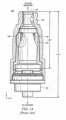
- FIGURE 1A is a cut-away view of a current needleless access connector 100.
- Needleless access connector 100 includes female luer fitting 101, male luer fitting 102, and valve 103.
- male luer fitting 102 is connected to, e . g ., a catheter or to a female luer
- female luer fitting 101 is connected to a fluid reservoir, e . g ., an IV bag or male luer.
- Female luer fitting 101 is connected to the fluid reservoir via a second male luer fitting 106, which has a hollow member (as shown in FIGURE 1B ) and is inserted through the top of female luer fitting 101.
- FIGURE 1B shows collapsible valve 103 in the collapsed position after insertion of male luer 106 into female luer 101.
- Male luer 106 delivers fluid, e . g ., from an IV bag, which flows around valve 103 into channels in male luer fitting 102 and into the catheter or female luer.
- Needleless access connector 100 is a positive displacement device, so that when a new connection is made at female luer fitting 101, device 100 pulls fluid in from the male side of the valve ( i . e ., the side proximate male luer fitting 102). When a disconnection is made at female luer fitting 101, device 100 pushes fluid in from the female side ( i . g ., the side proximate the top of female luer fitting 101).
- the advantage of positive displacement is that when a disconnection is made, device 100 expels fluid out of the male luer fitting 102 and effectively flushes the catheter.
- valve 103 In operation, when the female end of needleless access connector 100 is accessed by a male luer ( FIGURE 1B ), valve 103 is sufficiently elastic so that it can bend out of the way to allow flow and then return to its original shape after a disconnection is made at the female end. Thus, needleless access connector 100 re-seals itself and forms a flat surface that can be disinfected at the top surface 110 using an alcohol swab.
- Needleless access connector 100 has a partially annular valve body because it has weakness points on both sides by virtue of duckbills 105. Duckbills 105 encourage the collapse of collapsible valve 103. Furthermore, needleless access connector 100 includes uniform wall thickness in the valve body, even at and around duckbills 105.
- needleless access connector 100 Before needleless access connector 100 is used to connect a device to, for example a catheter, needleless access connector 100 will contain some air. This air is removed before using needleless access connector 100 with a catheter because otherwise it may be pumped into the patient causing harm to the patient. Usually, to remove this air, the medical practitioner inverts the needleless access connector and attaches a syringe containing saline to the needleless access connector. The saline is then pushed through the needleless access connector, thereby expelling the air from the connector. (This process is known as priming, and the minimum volume of liquid required to remove all the air from the needleless access connector is known as the priming volume.) Some medical practitioners prefer needleless access connectors with smaller priming volumes to reduce delay in medication delivery.
- the medical practitioner After a needleless access connector is primed, the medical practitioner usually connects the male end 102 to a catheter (not shown) The medical practitioner connects a male luer from the IV bag (not shown) to the needleless access connector. For example, a medical practitioner would connect the end of syringe 106 to female luer fitting 101, as shown in FIGURE 1B .
- needleless access connectors are significant especially in view of the fact that some of these medical practitioners, such as nurses, have to perform connecting of needleless access connectors many times during the course of a day.
- US 2006/089603 A1 relates to a fluid control device for transferring fluids.
- the fluid control device may incorporate a needleless access device.
- the fluid control device may comprise a housing having a first port, a second port, a third port and a connecting portion for connecting the first, second and third ports to each other.
- a first valve element may be positioned in the first port.
- US 2006/163515 A1 relates to fluid handling devices, particularly for medical purposes, and methods of making fluid handling devices, particularly suitable for needlefree access devices and check valves.
- WO 2007/008511 A2 relates generally to medical connectors through which fluids flow, and in particular, to medical connectors with male luers.
- the present disclosure is directed to positive displacement needleless access connectors that have a small priming volume.
- One embodiment is a collapsible valve for use in a needleless access connector.
- the collapsible valve includes a first portion with at least one smiley cut in a section of this first portion.
- the collapsible valve has a length of 15.75 to 20.83 mm (0.62 to 0.82 inches).
- the collapsible valve is adapted to provide positive displacement.
- Another embodiment is a positive displacement needleless access connector that includes a housing and a collapsible valve disposed in the housing.
- the collapsible valve has a length of 15.75 to 20.83 mm (0.62 to 0.82 inches).
- An apparatus is a positive displacement needleless access connector that includes a housing and a collapsible valve disposed in the housing. The housing and the valve cooperate so that a volume of liquid required to expel air from the needleless access connector is about 0.17 to 0.19 milliliters.
- a method according to one embodiment is for connecting a first medical device to a second medical device with a needleless access connector.
- the method includes inserting a male luer of the needleless access connector into the female luer of the second medical device.
- the method further includes inserting a male luer section of the first medical device into a female luer of the needleless access connector.
- the needleless access connector is a positive displacement needleless access connector that includes a housing and a collapsible valve disposed in the housing.
- the collapsible valve has a length of 15.75 to 20.83 mm (0.62 to 0.82 inches).
- the priming volumes of needleless access connectors that employ the configuration of valve 200-miniaturized collapsible valves with a significant portion of the outside surface being annular-may have a priming volume of around 0.175 milliliters and concomitantly allow good flow rates, though various embodiments may have different priming volumes.
- the priming volume may range from 0.17 to 0.19 milliliters.
- collapsible valve 200 may have an annular outside surface.
- collapsible valve 200 includes first portion 200A, second portion 200B and third portion 200C.
- First portion 200A does not have a significant annular outside surface because it has a smiley cut 200D interrupting the annular characteristic.
- second portion 200B and third portion 200C both have annular outside surfaces.
- FIGURE 2B shows second portion 200B cut in a plane, x, perpendicular to plane y.
- the annular outside surface shown in FIGURE 2B relative to plane y is circular.
- FIGURE 2C shows another possible annular outside surface. It should be noted that the axial length of the annular outside surface does not include portions of the outside surface with collapse assistance structures such as smiley cuts and duckbills.
- collapsible valve 201 has less axial length of its annular surface than does collapsible valve 200 by virtue of the duckbills on second portion 201B which interrupt the annular characteristic.
- Collapsible valve 202 has even less axial length of its annular surface by virtue of its duckbills that dominate second portion 202B.
- FIGURE 2A illustrates exemplary embodiments of the invention.
- Collapsible valves 200 to 202 are miniaturized valves that may be used in a needleless access connector.
- Collapsible valves 200 to 202 have smiley cuts, 200D to 202D in first portions 200A to 202A, respectively.
- Collapsible valves 200 to 202 have a height (axial length) of 18.29 mm (0.72 inches) but may be within the range of 15.75 mm to 20.83 mm (0.62 to 0.82 inches) in various embodiments.
- Collapsible valves 200 to 202 are adapted to provide positive displacement, in part, by virtue of voids 200E to 202E. Before the needleless access connectors, in which collapsible valves 200 to 202 are installed, are put in use, voids 200E to 202E contain air.
- FIGURE 2A illustrates that, in various embodiments of the invention, the annular portion of the outside surface of the collapsible valve spans about 30% to 66% of the total axial length of the collapsible valve.
- Collapsible valves 200 to 202 have a total axial length of 18.29 mm (0.72 inches).
- the amount of axial length of the annular surface varies amongst valves 200 to 202 by virtue of the amount and size of the collapse assistance structures present in each of these valves.
- Each of these valves has smiley cuts in first portions 200A to 202A that cause a portion of the axial length of valves 200 to 202 not to have an annular outside surface.
- first portions 200A to 202A does not have an annular outside surface.
- First portions 200A to 202A have an axial length of about 6.35 mm (0.25 inches) or about 34% of the total axial length of valves 200 to 202.
- at least 34% of the axial lengths of valves 200 to 202 do not have an annular outside surface because of smiley cuts 200D to 202D.
- second portion 200B and third portion 200C have annular outside surfaces. These annular portions represent the other 66% of the axial length of valve 200 (apart from first portion 200A) that has an annular outside surface.
- second portion 200B has an axial length of about 10.16 mm (0.4 inches) or about 56% of the total axial length of valve 200.
- Third portion 200C has an axial length of about 1.78 mm (0.07 inches) or about 10% of the total axial length of valve 200.
- Collapsible valves 201 and 202 have even less outside annular surface than collapsible valve 200 because of the duckbills in second portions 201B and 202B.
- Collapsible valve 202 for example, with the larger duckbills, may have an annular outside surface that spans about 30% of the axial length of valve 202 ( i.e ., 20% provided from second portion 202B and 10% provided by third portion 202C).
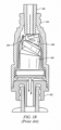
- FIGURE 3A is a cut-away view of exemplary needleless access connector 300 according to one embodiment of the invention.
- Needleless access connector 300 includes housing 301.
- Housing 301 may be of material including polycarbonate, polystyrene and acrylonitrile butadiene styrene.
- Housing 301 comprises top threaded part 302. It should be noted that the configuration of top threaded part 302, in some embodiments, meets ISO standard 594. Similarly, the configurations of male luer 303 at the base of needleless access connector 300, in some embodiments, meets ISO standard 594.
- Collapsible valve 304 is disposed within housing 301.
- Collapsible valve 304 may be made of elastic material such as silicone rubber, which is deformable and biocompatible. Because collapsible valve 304 is made of deformable material, it will collapse when sufficient force is applied to it.
- Collapsible valve 304 includes first portion 304A, which is disposed within top threaded part 302 when valve 304 is in its uncollapsed state as depicted in FIGURE 3A .
- First portion 304A may be substantially cylindrical in shape and may contain deviations from this cylindrical shape such as smiley cut 304B.
- Collapsible valve 304 also includes second portion 304C which is disposed in cavity 305 of housing 301.
- second portion 304C is devoid of duckbills or any other such deviations from its general shape, i.e ., portion 304C's outside surface is annular.
- second portion 304C is cylindrical and has diameter d2 being greater than diameter d1 of first portion 304A.
- Collapsible valve 304 may also include third portion 304D.
- Third portion 304D may have diameter d3 that is larger than second portion 304C's diameter, d2.
- Collapsible valve 304 controls fluid flow through needleless access connector 200 and thereby provides a way of connecting devices to a catheter.
- collapsible valve 304 In its uncollapsed state, as shown in FIGURE 3A , collapsible valve 304 seals top threaded part 302. A further seal is provided at shoulder 307 by collapsible valve 304.
- collapsible valve 304 When male luer 303 is connected to the catheter 308, in creating a seal at opening 306 and shoulder 307, collapsible valve 304 also seals catheter 308.
- male luer 309 is inserted in opening 306 as shown in FIGURE 3B .
- Collapsible valve 304 collapses as a result of the force imparted by male luer 309 and thereby allows fluid to flow from male luer 309 through needleless access connector 300, around valve 304 and into catheter 308, as shown in FIGURE 3B .
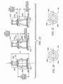
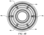
- housing 301 includes flow channels 401 as shown in FIGURES 4A and 4B .
- flow channels 401 assist the flow of fluid around collapsible valve 304 and into the catheter.
- flow channels 401 may be disposed in the upper portions of housing 401.
- FIGURES 4A and 4B show six flow channels 401 on the inside of housing 301, which promotes fluid flow.
- the width of flow channel 401 is half the width of flow channels in typical needleless access connectors.
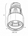
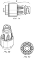
- FIGURES 5A - 5C show outside views of exemplary needleless access connectors according to one embodiment of the invention. It should be noted that the specific values given above are for exemplary embodiments and other embodiments may have somewhat different values. Other configurations with different sizes and shapes are within the scope of embodiments. In fact, any of a variety of positive displacement devices (and/or valves) can be adapted according to the concepts illustrated in the examples above.
Landscapes
- Health & Medical Sciences (AREA)
- Heart & Thoracic Surgery (AREA)
- Pulmonology (AREA)
- Engineering & Computer Science (AREA)
- Anesthesiology (AREA)
- Biomedical Technology (AREA)
- Hematology (AREA)
- Life Sciences & Earth Sciences (AREA)
- Animal Behavior & Ethology (AREA)
- General Health & Medical Sciences (AREA)
- Public Health (AREA)
- Veterinary Medicine (AREA)
- Infusion, Injection, And Reservoir Apparatuses (AREA)
- Quick-Acting Or Multi-Walled Pipe Joints (AREA)
Description
- This disclosure relates to needleless access connectors and more particularly to positive displacement needleless access connectors that have a small priming volume.
- Modem medical treatment often requires medical professionals to introduce fluids into a patient or withdraw fluids from a patient. For example, a patient may need treatment that requires a medical professional to withdraw urine or blood from the urethra or a vein, respectively. Conversely, the medical professional may need to introduce drugs or nutrients into the patient's vein (i.e., intravenously). To create a path for the flow of fluid into or from the patient, one method requires that the medical practitioner use a catheter where one end of the catheter is inserted into the patient. The other end of the catheter connects to an intravenous bag (IV bag), through an IV line. Needleless access connectors employ valves that allow a medical practitioner to remove or add devices (e.g., IV bags) to the catheter without the use of a needle. An example of a needleless access connector is shown in
FIGURES 1A and1B . -
FIGURE 1A is a cut-away view of a currentneedleless access connector 100.Needleless access connector 100 includesfemale luer fitting 101,male luer fitting 102, andvalve 103. When in use,male luer fitting 102 is connected to, e.g., a catheter or to a female luer, andfemale luer fitting 101 is connected to a fluid reservoir, e.g., an IV bag or male luer.Female luer fitting 101 is connected to the fluid reservoir via a secondmale luer fitting 106, which has a hollow member (as shown inFIGURE 1B ) and is inserted through the top of female luer fitting 101. The insertion ofmale luer 106 collapsesvalve 103 down intovolume 104 to break the seal and create a fluid flow path.FIGURE 1B showscollapsible valve 103 in the collapsed position after insertion ofmale luer 106 intofemale luer 101.Male luer 106 delivers fluid, e.g., from an IV bag, which flows aroundvalve 103 into channels in male luer fitting 102 and into the catheter or female luer. - Inside
valve 103 is a gap (or septum, not shown), that is filled with air.Needleless access connector 100 is a positive displacement device, so that when a new connection is made at female luer fitting 101,device 100 pulls fluid in from the male side of the valve (i.e., the side proximate male luer fitting 102). When a disconnection is made at female luer fitting 101,device 100 pushes fluid in from the female side (i.g., the side proximate the top of female luer fitting 101). The advantage of positive displacement is that when a disconnection is made,device 100 expels fluid out of the male luer fitting 102 and effectively flushes the catheter. By contrast, some devices on the market today have negative displacement, so that when a male luer (e.g., male luer 106) is disconnected, such devices pull a small amount of liquid from themale luer 102 side. When liquid is pulled from themale luer 102 side of a catheter that is attached to the vein of a patient, blood could be pulled into the catheter lumen and if this blood is left in the catheter lumen it may clot and cause health problems for the patient. Positive displacement connectors avoid this problem by pushing fluid out when a male luer (e.g., male luer 106) is disconnected from the needleless access connector and its collapsible valve moves from its collapsed state to its uncollapsed state. The purging of fluid, from positive displacement connectors, helps to prevent blood from entering the tip of the catheter, thereby preventing blood clotting/contamination and thus, bloodstream infections. - In operation, when the female end of
needleless access connector 100 is accessed by a male luer (FIGURE 1B ),valve 103 is sufficiently elastic so that it can bend out of the way to allow flow and then return to its original shape after a disconnection is made at the female end. Thus,needleless access connector 100 re-seals itself and forms a flat surface that can be disinfected at thetop surface 110 using an alcohol swab. -
Needleless access connector 100 has a partially annular valve body because it has weakness points on both sides by virtue ofduckbills 105.Duckbills 105 encourage the collapse ofcollapsible valve 103. Furthermore,needleless access connector 100 includes uniform wall thickness in the valve body, even at and aroundduckbills 105. - Before
needleless access connector 100 is used to connect a device to, for example a catheter,needleless access connector 100 will contain some air. This air is removed before usingneedleless access connector 100 with a catheter because otherwise it may be pumped into the patient causing harm to the patient. Usually, to remove this air, the medical practitioner inverts the needleless access connector and attaches a syringe containing saline to the needleless access connector. The saline is then pushed through the needleless access connector, thereby expelling the air from the connector. (This process is known as priming, and the minimum volume of liquid required to remove all the air from the needleless access connector is known as the priming volume.) Some medical practitioners prefer needleless access connectors with smaller priming volumes to reduce delay in medication delivery. - After a needleless access connector is primed, the medical practitioner usually connects the
male end 102 to a catheter (not shown) The medical practitioner connects a male luer from the IV bag (not shown) to the needleless access connector. For example, a medical practitioner would connect the end ofsyringe 106 to female luer fitting 101, as shown inFIGURE 1B . - The preferences of medical practitioners, discussed above regarding needleless access connectors, are significant especially in view of the fact that some of these medical practitioners, such as nurses, have to perform connecting of needleless access connectors many times during the course of a day.
-
US 2006/089603 A1 relates to a fluid control device for transferring fluids. In particular, the fluid control device may incorporate a needleless access device. The fluid control device may comprise a housing having a first port, a second port, a third port and a connecting portion for connecting the first, second and third ports to each other. A first valve element may be positioned in the first port. -
US 2006/163515 A1 relates to fluid handling devices, particularly for medical purposes, and methods of making fluid handling devices, particularly suitable for needlefree access devices and check valves. -
WO 2007/008511 A2 relates generally to medical connectors through which fluids flow, and in particular, to medical connectors with male luers. - The invention is defined by the claims. In the following, parts of the description and drawings referring to embodiments which are not covered by the claims are not presented as embodiments of the invention, but as examples useful for understanding the invention.
- The present disclosure is directed to positive displacement needleless access connectors that have a small priming volume. One embodiment is a collapsible valve for use in a needleless access connector. The collapsible valve includes a first portion with at least one smiley cut in a section of this first portion. The collapsible valve has a length of 15.75 to 20.83 mm (0.62 to 0.82 inches). Further, the collapsible valve is adapted to provide positive displacement. Another embodiment is a positive displacement needleless access connector that includes a housing and a collapsible valve disposed in the housing. The collapsible valve has a length of 15.75 to 20.83 mm (0.62 to 0.82 inches). An apparatus according to one embodiment is a positive displacement needleless access connector that includes a housing and a collapsible valve disposed in the housing. The housing and the valve cooperate so that a volume of liquid required to expel air from the needleless access connector is about 0.17 to 0.19 milliliters.
- Another embodiment is a positive displacement needleless access connector that includes a housing and a collapsible valve disposed in the housing. A method according to one embodiment is for connecting a first medical device to a second medical device with a needleless access connector. The method includes inserting a male luer of the needleless access connector into the female luer of the second medical device. The method further includes inserting a male luer section of the first medical device into a female luer of the needleless access connector. The needleless access connector is a positive displacement needleless access connector that includes a housing and a collapsible valve disposed in the housing. The collapsible valve has a length of 15.75 to 20.83 mm (0.62 to 0.82 inches).
- For a more complete understanding of the present invention, reference is now made to the following descriptions taken in conjunction with the accompanying drawings, in which:
-
FIGURES 1A and1B are cut-away views of a prior art needleless access connector; -
FIGURE 2A shows three exemplary collapsible valves used in tests of needleless access connectors; -
FIGURES 2B - 2C are cut-away, top-down views of different exemplary configurations of a valve according to embodiments of the invention; -
FIGURES 3A and3B illustrate different views of an exemplary needleless access connector according to one embodiment of the invention; -
FIGURES 4A and4B show flow channels in the housing of an exemplary needleless access connector according to one embodiment of the invention; and -
FIGURES 5A-5C illustrate different views of the housing of an exemplary needleless access connector according to one embodiment of the invention. - To address the issues of reducing priming volume, different configurations of valves for needleless access connectors are disclosed. Tests were performed to establish operability and priming volume for each positive displacement needleless access connector. Priming volume is the minimum volume of liquid used to purge air from the needleless access connector. The tests were conducted on three needleless access connectors each containing different collapsible valves. The configurations of the three different cdlapsible valves are shown in
FIGURE 2A . It was observed that the amount and size of the duckbills, which are known in the prior art as being an important part of some collapsible valves, and the reduction in length of the collapsible valve, as compared to prior art valves, affects priming volume of a needleless access connector. - In one test where the duckbills were completely removed from the collapsible valve (valve 200) and the valve was reduced to 18.29 mm (0.72 inches) from a typical length of a prior art valve of 23.37 mm (0.92 inches), it was observed that the priming volume for this valve was lower than the two other valves---
valve 201, which had small duckbills andvalve 202, which had large duckbills. It should be noted that reducing the compressible valve length from 23.37 mm to 18.29 mm (0.92 inches to 0.72 inches) allows for the reduction in total device length from 33.53 mm to 28.45 mm (1.32 inches to 1.12 inches). Some test results are shown in TABLE I below.TABLE I Illustration in FIGURE 2A Priming volume (milliliters) Cylindrical Valve 200 0.175 Small Duck Bill Valve 201 0.187 Large Duck Bill Valve 202 0.204 - The results of the tests indicate that the priming volumes of needleless access connectors that employ the configuration of valve 200-miniaturized collapsible valves with a significant portion of the outside surface being annular-may have a priming volume of around 0.175 milliliters and concomitantly allow good flow rates, though various embodiments may have different priming volumes. For example, the priming volume may range from 0.17 to 0.19 milliliters.
- Different configurations of
collapsible valve 200 may have an annular outside surface. For example,collapsible valve 200 includesfirst portion 200A,second portion 200B andthird portion 200C.First portion 200A does not have a significant annular outside surface because it has asmiley cut 200D interrupting the annular characteristic. In contrast,second portion 200B andthird portion 200C both have annular outside surfaces.FIGURE 2B showssecond portion 200B cut in a plane, x, perpendicular to plane y. The annular outside surface shown inFIGURE 2B relative to plane y is circular.FIGURE 2C shows another possible annular outside surface. It should be noted that the axial length of the annular outside surface does not include portions of the outside surface with collapse assistance structures such as smiley cuts and duckbills. For instance,collapsible valve 201 has less axial length of its annular surface than doescollapsible valve 200 by virtue of the duckbills onsecond portion 201B which interrupt the annular characteristic.Collapsible valve 202 has even less axial length of its annular surface by virtue of its duckbills that dominatesecond portion 202B. -
FIGURE 2A illustrates exemplary embodiments of the invention.Collapsible valves 200 to 202 are miniaturized valves that may be used in a needleless access connector.Collapsible valves 200 to 202 have smiley cuts, 200D to 202D infirst portions 200A to 202A, respectively.Collapsible valves 200 to 202 have a height (axial length) of 18.29 mm (0.72 inches) but may be within the range of 15.75 mm to 20.83 mm (0.62 to 0.82 inches) in various embodiments.Collapsible valves 200 to 202 are adapted to provide positive displacement, in part, by virtue ofvoids 200E to 202E. Before the needleless access connectors, in whichcollapsible valves 200 to 202 are installed, are put in use,voids 200E to 202E contain air. -
FIGURE 2A illustrates that, in various embodiments of the invention, the annular portion of the outside surface of the collapsible valve spans about 30% to 66% of the total axial length of the collapsible valve.Collapsible valves 200 to 202 have a total axial length of 18.29 mm (0.72 inches). The amount of axial length of the annular surface varies amongstvalves 200 to 202 by virtue of the amount and size of the collapse assistance structures present in each of these valves. Each of these valves has smiley cuts infirst portions 200A to 202A that cause a portion of the axial length ofvalves 200 to 202 not to have an annular outside surface. In other words, the axial length offirst portions 200A to 202A does not have an annular outside surface.First portions 200A to 202A have an axial length of about 6.35 mm (0.25 inches) or about 34% of the total axial length ofvalves 200 to 202. Thus, at least 34% of the axial lengths ofvalves 200 to 202 do not have an annular outside surface because ofsmiley cuts 200D to 202D. - Considering
valve 200,second portion 200B andthird portion 200C have annular outside surfaces. These annular portions represent the other 66% of the axial length of valve 200 (apart fromfirst portion 200A) that has an annular outside surface. Specifically,second portion 200B has an axial length of about 10.16 mm (0.4 inches) or about 56% of the total axial length ofvalve 200.Third portion 200C has an axial length of about 1.78 mm (0.07 inches) or about 10% of the total axial length ofvalve 200. -
Collapsible valves collapsible valve 200 because of the duckbills insecond portions Collapsible valve 202 for example, with the larger duckbills, may have an annular outside surface that spans about 30% of the axial length of valve 202 (i.e., 20% provided fromsecond portion 202B and 10% provided by third portion 202C). -
FIGURE 3A is a cut-away view of exemplaryneedleless access connector 300 according to one embodiment of the invention.Needleless access connector 300 includeshousing 301.Housing 301 may be of material including polycarbonate, polystyrene and acrylonitrile butadiene styrene.Housing 301 comprises top threadedpart 302. It should be noted that the configuration of top threadedpart 302, in some embodiments, meets ISO standard 594. Similarly, the configurations ofmale luer 303 at the base ofneedleless access connector 300, in some embodiments, meets ISO standard 594.Collapsible valve 304 is disposed withinhousing 301. -
Collapsible valve 304 may be made of elastic material such as silicone rubber, which is deformable and biocompatible. Becausecollapsible valve 304 is made of deformable material, it will collapse when sufficient force is applied to it.Collapsible valve 304 includesfirst portion 304A, which is disposed within top threadedpart 302 whenvalve 304 is in its uncollapsed state as depicted inFIGURE 3A .First portion 304A may be substantially cylindrical in shape and may contain deviations from this cylindrical shape such as smiley cut 304B.Collapsible valve 304 also includessecond portion 304C which is disposed incavity 305 ofhousing 301. Unlike the prior art as depicted inFIGURE 1 ,second portion 304C is devoid of duckbills or any other such deviations from its general shape, i.e.,portion 304C's outside surface is annular. As such, in one embodiment,second portion 304C is cylindrical and has diameter d2 being greater than diameter d1 offirst portion 304A.Collapsible valve 304 may also includethird portion 304D.Third portion 304D may have diameter d3 that is larger thansecond portion 304C's diameter, d2. -
Collapsible valve 304 controls fluid flow throughneedleless access connector 200 and thereby provides a way of connecting devices to a catheter. In its uncollapsed state, as shown inFIGURE 3A ,collapsible valve 304 seals top threadedpart 302. A further seal is provided atshoulder 307 bycollapsible valve 304. Whenmale luer 303 is connected to thecatheter 308, in creating a seal atopening 306 andshoulder 307,collapsible valve 304 also sealscatheter 308. To connect another device, such as an IV bag, tocatheter 308,male luer 309 is inserted in opening 306 as shown inFIGURE 3B .Collapsible valve 304 collapses as a result of the force imparted bymale luer 309 and thereby allows fluid to flow frommale luer 309 throughneedleless access connector 300, aroundvalve 304 and intocatheter 308, as shown inFIGURE 3B . - In some embodiments of the invention,
housing 301 includesflow channels 401 as shown inFIGURES 4A and4B . Whencollapsible valve 304 is in a collapsed state, flowchannels 401 assist the flow of fluid aroundcollapsible valve 304 and into the catheter. As indicated inFIGURE 4A , flowchannels 401 may be disposed in the upper portions ofhousing 401.FIGURES 4A and4B show sixflow channels 401 on the inside ofhousing 301, which promotes fluid flow. In some embodiments, the width offlow channel 401 is half the width of flow channels in typical needleless access connectors. -
FIGURES 5A - 5C show outside views of exemplary needleless access connectors according to one embodiment of the invention. It should be noted that the specific values given above are for exemplary embodiments and other embodiments may have somewhat different values. Other configurations with different sizes and shapes are within the scope of embodiments. In fact, any of a variety of positive displacement devices (and/or valves) can be adapted according to the concepts illustrated in the examples above. - Although the present invention and its advantages have been described in detail, it should be understood that various changes, substitutions and alterations can be made herein without departing from the spirit and scope of the invention as defined by the appended claims. Moreover, the scope of the present application is not intended to be limited to the particular embodiments of the process, machine, manufacture, composition of matter, means, methods and steps described in the specification. As one of ordinary skill in the art will readily appreciate from the disclosure of the present invention, processes, machines, manufacture, compositions of matter, means, methods, or steps, presently existing or later to be developed that perform substantially the same function or achieve substantially the same result as the corresponding embodiments described herein may be utilized according to the present invention. Accordingly, the scope of the application is defined by the appended claims.
Claims (10)
- A needleless access connector (300) for connecting medical devices, the connector comprising:a housing (301) comprisinga male Luer fitting at one end; anda female Luer fitting at the other end; anda collapsible valve (200, 304) disposed in a cavity (305) of the housing (301), the collapsible valve having a first axial length from 15.75 to 20.83 mm and comprising:a cylindrical first portion (200A, 304A) with at least one arcuate cut (200D, 304B) in a section thereof and having a second axial length , wherein the first portion (200A, 304A) of the collapsible valve (200, 304) creates a seal at an opening (306) of the housing (301); anda cylindrical second portion (200B, 304C) being coupled to the first portion (200A, 304A) and having a void (200E), a third axial length, and an annular outside surface over the entire third axial length, wherein the annular outside surface spans 56% of the first axial length of the collapsible valve,wherein the collapsible valve (200, 304) is configured to provide a positive displacement when collapsed by insertion of a male luer (309) into the opening (306) such that a fluid is allowed to move around the valve (200, 304) and between the male and female Luer fittings, and wherein the housing and collapsible valve are configured to provide and a priming volume that is from 0.17 to 0.19 milliliters.
- The connector of any of Claim 1, wherein the collapsible valve (304) comprises an elastic material.
- The connector of any of Claims 1 and 2, wherein the housing comprises at least one channel adapted to allow fluid to flow through when the collapsible valve is collapsed.
- The connector of any of Claims 1, 2, and 3, wherein the needleless access connector has a length of 25.91 to 28.70mm.
- The connector of any of Claims 1 and 2-4, wherein the housing is made from polycarbonate, polystyrene, or acrylonitrile butadiene styrene.
- The needleless access connector of Claim 1, wherein the first portion comprises an end that, when the collapsible valve (200, 304) is in an uncollapsed state, is flush with the opening of the housing.
- The needleless access connector of Claim 6, wherein the end of the first portion has a first diameter, and the outside surface of the second portion has a second diameter that is larger than the first diameter.
- A method of connecting a first medical device to a second medical device using the connector of any of Claims 1-7, the method comprising the steps of:inserting a male Luer of the first medical device into the female Luer of the connector: andinserting the male Luer of the connector into a female Luer of the second medical device.
- The method of Claim 8, wherein the first medical device comprises an IV bag and the second medical device comprises a catheter.
- The connector of Claim 1, further comprising a third portion (200C, 304D) having a diameter that is larger than the first and second portions.
Priority Applications (1)
| Application Number | Priority Date | Filing Date | Title |
|---|---|---|---|
| EP23174847.6A EP4233981A3 (en) | 2009-11-16 | 2010-11-15 | Needleless access connectors and valve elements therefor |
Applications Claiming Priority (4)
| Application Number | Priority Date | Filing Date | Title |
|---|---|---|---|
| US95980909P | 2009-11-16 | 2009-11-16 | |
| US12/619,598 US8636720B2 (en) | 2009-11-16 | 2009-11-16 | Needleless access connectors and valve elements therefor |
| EP10779435.6A EP2501435B1 (en) | 2009-11-16 | 2010-11-15 | Needleless access connectors and valve elements therefor |
| PCT/US2010/056749 WO2011060384A1 (en) | 2009-11-16 | 2010-11-15 | Needleless access connectors and valve elements therefor |
Related Parent Applications (2)
| Application Number | Title | Priority Date | Filing Date |
|---|---|---|---|
| EP10779435.6A Division EP2501435B1 (en) | 2009-11-16 | 2010-11-15 | Needleless access connectors and valve elements therefor |
| EP10779435.6A Division-Into EP2501435B1 (en) | 2009-11-16 | 2010-11-15 | Needleless access connectors and valve elements therefor |
Related Child Applications (2)
| Application Number | Title | Priority Date | Filing Date |
|---|---|---|---|
| EP23174847.6A Division EP4233981A3 (en) | 2009-11-16 | 2010-11-15 | Needleless access connectors and valve elements therefor |
| EP23174847.6A Division-Into EP4233981A3 (en) | 2009-11-16 | 2010-11-15 | Needleless access connectors and valve elements therefor |
Publications (2)
| Publication Number | Publication Date |
|---|---|
| EP3603733A1 EP3603733A1 (en) | 2020-02-05 |
| EP3603733B1 true EP3603733B1 (en) | 2023-08-02 |
Family
ID=43479373
Family Applications (3)
| Application Number | Title | Priority Date | Filing Date |
|---|---|---|---|
| EP23174847.6A Pending EP4233981A3 (en) | 2009-11-16 | 2010-11-15 | Needleless access connectors and valve elements therefor |
| EP10779435.6A Active EP2501435B1 (en) | 2009-11-16 | 2010-11-15 | Needleless access connectors and valve elements therefor |
| EP19192864.7A Active EP3603733B1 (en) | 2009-11-16 | 2010-11-15 | Needleless access connectors and valve elements therefor |
Family Applications Before (2)
| Application Number | Title | Priority Date | Filing Date |
|---|---|---|---|
| EP23174847.6A Pending EP4233981A3 (en) | 2009-11-16 | 2010-11-15 | Needleless access connectors and valve elements therefor |
| EP10779435.6A Active EP2501435B1 (en) | 2009-11-16 | 2010-11-15 | Needleless access connectors and valve elements therefor |
Country Status (10)
| Country | Link |
|---|---|
| US (5) | US8636720B2 (en) |
| EP (3) | EP4233981A3 (en) |
| JP (1) | JP6030959B2 (en) |
| CN (1) | CN102686265B (en) |
| AU (1) | AU2010320036B2 (en) |
| CA (1) | CA2779703C (en) |
| ES (2) | ES2764969T3 (en) |
| MX (1) | MX2012005480A (en) |
| RU (1) | RU2012117974A (en) |
| WO (1) | WO2011060384A1 (en) |
Families Citing this family (77)
| Publication number | Priority date | Publication date | Assignee | Title |
|---|---|---|---|---|
| US7600530B2 (en) | 2004-08-09 | 2009-10-13 | Medegen, Inc. | Connector with check valve and method of use |
| US20140276459A1 (en) * | 2013-03-13 | 2014-09-18 | Jonathan Yeh | Needleless connector with folding valve |
| US10478607B2 (en) | 2004-08-09 | 2019-11-19 | Carefusion 303, Inc. | Connector for transferring fluid and method of use |
| CN101068592B (en) | 2004-11-05 | 2010-12-08 | Icu医疗公司 | Medical Connectors Featuring High Flow Rates |
| EP1907042B1 (en) | 2005-07-06 | 2009-03-11 | Vascular Pathways Inc. | Intravenous catheter insertion device and method of use |
| US9168366B2 (en) | 2008-12-19 | 2015-10-27 | Icu Medical, Inc. | Medical connector with closeable luer connector |
| US8454579B2 (en) | 2009-03-25 | 2013-06-04 | Icu Medical, Inc. | Medical connector with automatic valves and volume regulator |
| CN104873389B (en) | 2009-07-29 | 2017-12-05 | Icu医学有限公司 | Fluid conveying device and application method |
| US8323249B2 (en) | 2009-08-14 | 2012-12-04 | The Regents Of The University Of Michigan | Integrated vascular delivery system |
| USD644731S1 (en) | 2010-03-23 | 2011-09-06 | Icu Medical, Inc. | Medical connector |
| US8298196B1 (en) | 2010-03-24 | 2012-10-30 | Mansour George M | Needleless access connector and method of use |
| US11925779B2 (en) | 2010-05-14 | 2024-03-12 | C. R. Bard, Inc. | Catheter insertion device including top-mounted advancement components |
| US9950139B2 (en) | 2010-05-14 | 2018-04-24 | C. R. Bard, Inc. | Catheter placement device including guidewire and catheter control elements |
| US8758306B2 (en) | 2010-05-17 | 2014-06-24 | Icu Medical, Inc. | Medical connectors and methods of use |
| US8814833B2 (en) | 2010-05-19 | 2014-08-26 | Tangent Medical Technologies Llc | Safety needle system operable with a medical device |
| US8771230B2 (en) | 2010-05-19 | 2014-07-08 | Tangent Medical Technologies, Llc | Integrated vascular delivery system |
| US9095683B2 (en) | 2011-02-25 | 2015-08-04 | C. R. Bard, Inc. | Medical component insertion device including a retractable needle |
| USD903101S1 (en) | 2011-05-13 | 2020-11-24 | C. R. Bard, Inc. | Catheter |
| AU2012271986A1 (en) * | 2011-06-22 | 2013-04-04 | Gambro Lundia Ab | Valve automatically opening on connection, and applications therefor |
| US9067049B2 (en) * | 2011-07-25 | 2015-06-30 | Carefusion 303, Inc. | Providing positive displacement upon disconnection using a connector with a dual diaphragm valve |
| US9375561B2 (en) | 2011-09-02 | 2016-06-28 | Carefusion 303, Inc. | Self-flushing valve |
| EP3760275A1 (en) | 2011-09-09 | 2021-01-06 | ICU Medical, Inc. | Medical connectors with fluid-resistant mating interfaces |
| USD711516S1 (en) * | 2011-12-09 | 2014-08-19 | John Guest International Limited | Fluid connector |
| USD712014S1 (en) * | 2011-12-09 | 2014-08-26 | John Guest International Limited | Fluid connector |
| KR102741127B1 (en) | 2011-12-22 | 2024-12-11 | 아이씨유 메디칼 인코퍼레이티드 | A method of using an electronic medical fluid transfer system |
| US8801678B2 (en) * | 2012-01-20 | 2014-08-12 | Carefusion 303, Inc. | Piston for a needleless valve system |
| US9409007B2 (en) * | 2012-01-26 | 2016-08-09 | Carefusion 303, Inc. | Assembling a needleless valve system |
| US10359139B2 (en) | 2012-04-05 | 2019-07-23 | Medline Industries, Inc. | Connector |
| USD757259S1 (en) * | 2012-04-05 | 2016-05-24 | Medline Industries, Inc. | Female portion of a connector |
| US9162029B2 (en) * | 2012-11-09 | 2015-10-20 | Carefusion 303, Inc. | Tailless needleless valve system |
| WO2014074929A1 (en) | 2012-11-12 | 2014-05-15 | Icu Medical, Inc. | Medical connector |
| CN104755130B (en) * | 2013-01-28 | 2018-05-11 | 泰尔茂株式会社 | pipe connection structure |
| US9308362B2 (en) * | 2013-03-12 | 2016-04-12 | Carefusion 303, Inc. | Male luer with fluid path and vent path seals |
| US9144672B2 (en) | 2013-03-13 | 2015-09-29 | Carefusion 303, Inc. | Needleless connector with compressible valve |
| US8840577B1 (en) * | 2013-03-14 | 2014-09-23 | Carefusion 303, Inc. | Needleless connector with flexible valve |
| US9278205B2 (en) | 2013-03-13 | 2016-03-08 | Carefusion 303, Inc. | Collapsible valve with internal dimples |
| US9370651B2 (en) | 2013-03-13 | 2016-06-21 | Carefusion 303, Inc. | Needleless connector with reduced trapped volume |
| US9089682B2 (en) * | 2013-03-14 | 2015-07-28 | Carefusion 303, Inc. | Needleless connector with support member |
| US8708976B1 (en) * | 2013-03-14 | 2014-04-29 | Carefusion 303, Inc. | Needleless connector with a tortuous fluid flow path |
| ES2642360T3 (en) | 2013-03-15 | 2017-11-16 | Icu Medical, Inc. | Medical connector |
| EP2862587A1 (en) | 2013-10-15 | 2015-04-22 | Becton Dickinson France | Tip cap assembly for closing an injection system |
| JP6259113B2 (en) | 2013-11-25 | 2018-01-10 | アイシーユー・メディカル・インコーポレーテッド | Method and system for filling an infusion bag with therapeutic fluid |
| EP3079739B1 (en) | 2013-12-11 | 2023-02-22 | ICU Medical, Inc. | Check valve |
| EP3102258A4 (en) | 2014-02-04 | 2017-12-27 | ICU Medical, Inc. | Self-priming systems and methods |
| JP6563903B2 (en) | 2014-03-26 | 2019-08-21 | テルモ株式会社 | Connector and infusion set |
| WO2015187943A1 (en) | 2014-06-05 | 2015-12-10 | Puracath Medical, Inc. | Transfer catheter for ultraviolet disinfection |
| MX2017001442A (en) * | 2014-08-08 | 2017-05-19 | Vyaire Medical Consumables Llc | Wash port assemblies for airway adapters. |
| US10364914B2 (en) * | 2014-09-29 | 2019-07-30 | B. Braun Medical Inc. | Valve device, a delivery system including same and method |
| USD793551S1 (en) | 2014-12-03 | 2017-08-01 | Icu Medical, Inc. | Fluid manifold |
| USD786427S1 (en) | 2014-12-03 | 2017-05-09 | Icu Medical, Inc. | Fluid manifold |
| EP3270979B1 (en) | 2015-03-18 | 2020-08-19 | Puracath Medical, Inc. | Catheter connection system for ultraviolet light disinfection |
| CN104815363B (en) * | 2015-04-30 | 2018-11-02 | 苏州林华医疗器械股份有限公司 | A kind of positive pressure connector |
| USD903100S1 (en) | 2015-05-01 | 2020-11-24 | C. R. Bard, Inc. | Catheter placement device |
| CN116672577A (en) | 2015-05-15 | 2023-09-01 | C·R·巴德股份有限公司 | Catheter placement device including an extendable needle safety member |
| JP6709039B2 (en) * | 2015-07-09 | 2020-06-10 | 川澄化学工業株式会社 | Connecting pipe |
| CN205007361U (en) * | 2015-07-29 | 2016-02-03 | 佳承精工股份有限公司 | Positive pressure needle-free injection Y-shaped joint device |
| EP3662966A1 (en) * | 2015-10-28 | 2020-06-10 | Carefusion 303 Inc. | Closed iv access device with y-port needle-free connector |
| EP3383343A4 (en) | 2015-12-04 | 2019-07-10 | ICU Medical, Inc. | SYSTEMS, METHODS AND COMPONENTS FOR THE TRANSFER OF MEDICAL FLUIDS |
| ES3037643T3 (en) | 2016-07-11 | 2025-10-03 | Puracath Medical Inc | Point of care ultraviolet disinfection system |
| USD851745S1 (en) | 2016-07-19 | 2019-06-18 | Icu Medical, Inc. | Medical fluid transfer system |
| JP7046051B2 (en) | 2016-07-25 | 2022-04-01 | アイシーユー・メディカル・インコーポレーテッド | Systems and components for trapping air bubbles in medical fluid transfer modules and systems |
| CN109715093B (en) * | 2016-09-12 | 2020-11-06 | C·R·巴德股份有限公司 | Blood Control for Catheterization Devices |
| WO2018089643A1 (en) * | 2016-11-10 | 2018-05-17 | Puracath Medical, Inc. | Needleless connector valve |
| CA3054969A1 (en) | 2017-03-01 | 2018-09-07 | C.R. Bard, Inc. | Catheter insertion device |
| JP6945641B2 (en) * | 2017-05-19 | 2021-10-06 | エーディーヴィーケア メディカル インコーポレイテッド | Sealed system dispensing dosing device |
| WO2019173641A1 (en) | 2018-03-07 | 2019-09-12 | Bard Access Systems, Inc. | Guidewire advancement and blood flashback systems for a medical device insertion system |
| CN113853233A (en) * | 2019-03-22 | 2021-12-28 | 普拉卡斯医疗公司 | Needleless connector valve for UV disinfection |
| CN213312819U (en) | 2019-08-19 | 2021-06-01 | 贝克顿·迪金森公司 | Midline catheter placement device |
| US12440652B2 (en) | 2019-09-20 | 2025-10-14 | Bard Peripheral Vascular, Inc. | Intravenous catheter-placement device and method thereof |
| US12016961B2 (en) | 2019-10-04 | 2024-06-25 | Puracath Medical, Inc. | Point of care ultraviolet disinfection system |
| US11857752B2 (en) | 2019-12-16 | 2024-01-02 | Rymed Technologies, Llc | High flow, needleless connector |
| US11904131B2 (en) * | 2020-01-16 | 2024-02-20 | Carefusion 303, Inc. | Needleless connector having check valve with concave flow surface |
| US11590057B2 (en) | 2020-04-03 | 2023-02-28 | Icu Medical, Inc. | Systems, methods, and components for transferring medical fluids |
| CN113558974B (en) * | 2020-12-07 | 2025-01-21 | 刘云虎 | A positive and negative pressure needle-free rubber valve connector |
| US12036380B2 (en) * | 2021-05-04 | 2024-07-16 | Carefusion 303, Inc. | Needleless connector with compressible and deflectable valve |
| US11828388B2 (en) | 2022-03-08 | 2023-11-28 | B. Braun Medical Inc. | Needle-free connector |
| USD1105422S1 (en) | 2024-02-09 | 2025-12-09 | Icu Medical, Inc. | Medical connector cover |
Family Cites Families (14)
| Publication number | Priority date | Publication date | Assignee | Title |
|---|---|---|---|---|
| US5569235A (en) * | 1994-06-21 | 1996-10-29 | Modern Medical Devices | Valve and valved container for use with a syringe fitting |
| US5782816A (en) * | 1995-09-07 | 1998-07-21 | David R. Kipp | Bi-directional valve and method of using same |
| US5730418A (en) * | 1996-09-30 | 1998-03-24 | The Kipp Group | Minimum fluid displacement medical connector |
| US6706022B1 (en) * | 1999-07-27 | 2004-03-16 | Alaris Medical Systems, Inc. | Needleless medical connector with expandable valve mechanism |
| US20030208165A1 (en) | 2002-05-01 | 2003-11-06 | Christensen Kelly David | Needless luer access connector |
| WO2004112866A2 (en) | 2003-06-17 | 2004-12-29 | Filtertek Inc. | Fluid handling device and method of making same |
| US20050059952A1 (en) * | 2003-09-17 | 2005-03-17 | Giuliano Amy S. | I.V. solution bag with a needleless port |
| US7600530B2 (en) * | 2004-08-09 | 2009-10-13 | Medegen, Inc. | Connector with check valve and method of use |
| US7771383B2 (en) | 2004-10-22 | 2010-08-10 | Medegen, Inc. | Fluid control device with valve and methods of use |
| US20070088293A1 (en) * | 2005-07-06 | 2007-04-19 | Fangrow Thomas F Jr | Medical connector with closeable male luer |
| US9695953B2 (en) * | 2006-02-14 | 2017-07-04 | B. Braun Medical Inc. | Needleless access port valves |
| US7591449B2 (en) * | 2006-02-14 | 2009-09-22 | B. Braun Medical Inc. | Needleless access port valves |
| US20100036330A1 (en) * | 2008-08-11 | 2010-02-11 | Baxter International Inc. | Needleless connector with displacement correction |
| US8715247B2 (en) | 2009-07-30 | 2014-05-06 | Carefusion 303, Inc. | Collapsible valve |
-
2009
- 2009-11-16 US US12/619,598 patent/US8636720B2/en active Active
-
2010
- 2010-11-15 RU RU2012117974/14A patent/RU2012117974A/en not_active Application Discontinuation
- 2010-11-15 JP JP2012539059A patent/JP6030959B2/en active Active
- 2010-11-15 CN CN201080051198.6A patent/CN102686265B/en active Active
- 2010-11-15 MX MX2012005480A patent/MX2012005480A/en active IP Right Grant
- 2010-11-15 CA CA2779703A patent/CA2779703C/en active Active
- 2010-11-15 EP EP23174847.6A patent/EP4233981A3/en active Pending
- 2010-11-15 ES ES10779435T patent/ES2764969T3/en active Active
- 2010-11-15 ES ES19192864T patent/ES2961721T3/en active Active
- 2010-11-15 AU AU2010320036A patent/AU2010320036B2/en active Active
- 2010-11-15 EP EP10779435.6A patent/EP2501435B1/en active Active
- 2010-11-15 EP EP19192864.7A patent/EP3603733B1/en active Active
- 2010-11-15 WO PCT/US2010/056749 patent/WO2011060384A1/en not_active Ceased
-
2014
- 2014-01-27 US US14/165,349 patent/US9061130B2/en active Active
-
2015
- 2015-06-04 US US14/731,150 patent/US10258786B2/en active Active
-
2019
- 2019-04-12 US US16/383,445 patent/US11759619B2/en active Active
-
2023
- 2023-08-03 US US18/365,180 patent/US12109388B2/en active Active
Also Published As
| Publication number | Publication date |
|---|---|
| AU2010320036A1 (en) | 2012-05-24 |
| JP6030959B2 (en) | 2016-11-24 |
| WO2011060384A1 (en) | 2011-05-19 |
| US9061130B2 (en) | 2015-06-23 |
| EP4233981A2 (en) | 2023-08-30 |
| CA2779703C (en) | 2020-09-08 |
| US20120310179A1 (en) | 2012-12-06 |
| RU2012117974A (en) | 2013-12-27 |
| ES2764969T3 (en) | 2020-06-05 |
| US20140142519A1 (en) | 2014-05-22 |
| CN102686265A (en) | 2012-09-19 |
| JP2013510690A (en) | 2013-03-28 |
| CN102686265B (en) | 2014-11-19 |
| US11759619B2 (en) | 2023-09-19 |
| US20240001100A1 (en) | 2024-01-04 |
| AU2010320036B2 (en) | 2016-01-21 |
| US10258786B2 (en) | 2019-04-16 |
| CA2779703A1 (en) | 2011-05-19 |
| US12109388B2 (en) | 2024-10-08 |
| EP4233981A3 (en) | 2023-09-27 |
| US20190232043A1 (en) | 2019-08-01 |
| EP2501435A1 (en) | 2012-09-26 |
| US8636720B2 (en) | 2014-01-28 |
| US20150265829A1 (en) | 2015-09-24 |
| MX2012005480A (en) | 2012-08-01 |
| ES2961721T3 (en) | 2024-03-13 |
| EP2501435B1 (en) | 2019-10-23 |
| EP3603733A1 (en) | 2020-02-05 |
Similar Documents
| Publication | Publication Date | Title |
|---|---|---|
| US12109388B2 (en) | Needleless access connectors and valve elements therefor | |
| AU2016201947B2 (en) | New needleless access connector and method of use | |
| JP2013510690A5 (en) | ||
| TWI565493B (en) | Needleless access connectors and valve elements therefor | |
| TWI626063B (en) | Positive-displacement needleless access connector and method for manufacturing the same | |
| TWI565489B (en) | New needleless access connector and method of use | |
| TWI603752B (en) | Needleless access connector and method of controlling fluid |
Legal Events
| Date | Code | Title | Description |
|---|---|---|---|
| PUAI | Public reference made under article 153(3) epc to a published international application that has entered the european phase |
Free format text: ORIGINAL CODE: 0009012 |
|
| STAA | Information on the status of an ep patent application or granted ep patent |
Free format text: STATUS: THE APPLICATION HAS BEEN PUBLISHED |
|
| AC | Divisional application: reference to earlier application |
Ref document number: 2501435 Country of ref document: EP Kind code of ref document: P |
|
| AK | Designated contracting states |
Kind code of ref document: A1 Designated state(s): AL AT BE BG CH CY CZ DE DK EE ES FI FR GB GR HR HU IE IS IT LI LT LU LV MC MK MT NL NO PL PT RO RS SE SI SK SM TR |
|
| STAA | Information on the status of an ep patent application or granted ep patent |
Free format text: STATUS: REQUEST FOR EXAMINATION WAS MADE |
|
| 17P | Request for examination filed |
Effective date: 20200709 |
|
| RBV | Designated contracting states (corrected) |
Designated state(s): AL AT BE BG CH CY CZ DE DK EE ES FI FR GB GR HR HU IE IS IT LI LT LU LV MC MK MT NL NO PL PT RO RS SE SI SK SM TR |
|
| RIC1 | Information provided on ipc code assigned before grant |
Ipc: A61M 39/02 20060101ALI20221214BHEP Ipc: A61M 39/26 20060101ALI20221214BHEP Ipc: A61M 39/04 20060101AFI20221214BHEP |
|
| GRAP | Despatch of communication of intention to grant a patent |
Free format text: ORIGINAL CODE: EPIDOSNIGR1 |
|
| STAA | Information on the status of an ep patent application or granted ep patent |
Free format text: STATUS: GRANT OF PATENT IS INTENDED |
|
| INTG | Intention to grant announced |
Effective date: 20230217 |
|
| RIN1 | Information on inventor provided before grant (corrected) |
Inventor name: MAZZA, ALEX T. Inventor name: TRUITT, TIM L. |
|
| GRAS | Grant fee paid |
Free format text: ORIGINAL CODE: EPIDOSNIGR3 |
|
| GRAA | (expected) grant |
Free format text: ORIGINAL CODE: 0009210 |
|
| STAA | Information on the status of an ep patent application or granted ep patent |
Free format text: STATUS: THE PATENT HAS BEEN GRANTED |
|
| AC | Divisional application: reference to earlier application |
Ref document number: 2501435 Country of ref document: EP Kind code of ref document: P |
|
| AK | Designated contracting states |
Kind code of ref document: B1 Designated state(s): AL AT BE BG CH CY CZ DE DK EE ES FI FR GB GR HR HU IE IS IT LI LT LU LV MC MK MT NL NO PL PT RO RS SE SI SK SM TR |
|
| REG | Reference to a national code |
Ref country code: GB Ref legal event code: FG4D |
|
| REG | Reference to a national code |
Ref country code: CH Ref legal event code: EP |
|
| REG | Reference to a national code |
Ref country code: DE Ref legal event code: R096 Ref document number: 602010068952 Country of ref document: DE |
|
| REG | Reference to a national code |
Ref country code: IE Ref legal event code: FG4D |
|
| P01 | Opt-out of the competence of the unified patent court (upc) registered |
Effective date: 20230825 |
|
| REG | Reference to a national code |
Ref country code: LT Ref legal event code: MG9D |
|
| REG | Reference to a national code |
Ref country code: NL Ref legal event code: MP Effective date: 20230802 |
|
| REG | Reference to a national code |
Ref country code: AT Ref legal event code: MK05 Ref document number: 1593947 Country of ref document: AT Kind code of ref document: T Effective date: 20230802 |
|
| PG25 | Lapsed in a contracting state [announced via postgrant information from national office to epo] |
Ref country code: GR Free format text: LAPSE BECAUSE OF FAILURE TO SUBMIT A TRANSLATION OF THE DESCRIPTION OR TO PAY THE FEE WITHIN THE PRESCRIBED TIME-LIMIT Effective date: 20231103 |
|
| PG25 | Lapsed in a contracting state [announced via postgrant information from national office to epo] |
Ref country code: IS Free format text: LAPSE BECAUSE OF FAILURE TO SUBMIT A TRANSLATION OF THE DESCRIPTION OR TO PAY THE FEE WITHIN THE PRESCRIBED TIME-LIMIT Effective date: 20231202 |
|
| PG25 | Lapsed in a contracting state [announced via postgrant information from national office to epo] |
Ref country code: SE Free format text: LAPSE BECAUSE OF FAILURE TO SUBMIT A TRANSLATION OF THE DESCRIPTION OR TO PAY THE FEE WITHIN THE PRESCRIBED TIME-LIMIT Effective date: 20230802 Ref country code: RS Free format text: LAPSE BECAUSE OF FAILURE TO SUBMIT A TRANSLATION OF THE DESCRIPTION OR TO PAY THE FEE WITHIN THE PRESCRIBED TIME-LIMIT Effective date: 20230802 Ref country code: PT Free format text: LAPSE BECAUSE OF FAILURE TO SUBMIT A TRANSLATION OF THE DESCRIPTION OR TO PAY THE FEE WITHIN THE PRESCRIBED TIME-LIMIT Effective date: 20231204 Ref country code: NO Free format text: LAPSE BECAUSE OF FAILURE TO SUBMIT A TRANSLATION OF THE DESCRIPTION OR TO PAY THE FEE WITHIN THE PRESCRIBED TIME-LIMIT Effective date: 20231102 Ref country code: NL Free format text: LAPSE BECAUSE OF FAILURE TO SUBMIT A TRANSLATION OF THE DESCRIPTION OR TO PAY THE FEE WITHIN THE PRESCRIBED TIME-LIMIT Effective date: 20230802 Ref country code: LV Free format text: LAPSE BECAUSE OF FAILURE TO SUBMIT A TRANSLATION OF THE DESCRIPTION OR TO PAY THE FEE WITHIN THE PRESCRIBED TIME-LIMIT Effective date: 20230802 Ref country code: LT Free format text: LAPSE BECAUSE OF FAILURE TO SUBMIT A TRANSLATION OF THE DESCRIPTION OR TO PAY THE FEE WITHIN THE PRESCRIBED TIME-LIMIT Effective date: 20230802 Ref country code: IS Free format text: LAPSE BECAUSE OF FAILURE TO SUBMIT A TRANSLATION OF THE DESCRIPTION OR TO PAY THE FEE WITHIN THE PRESCRIBED TIME-LIMIT Effective date: 20231202 Ref country code: HR Free format text: LAPSE BECAUSE OF FAILURE TO SUBMIT A TRANSLATION OF THE DESCRIPTION OR TO PAY THE FEE WITHIN THE PRESCRIBED TIME-LIMIT Effective date: 20230802 Ref country code: GR Free format text: LAPSE BECAUSE OF FAILURE TO SUBMIT A TRANSLATION OF THE DESCRIPTION OR TO PAY THE FEE WITHIN THE PRESCRIBED TIME-LIMIT Effective date: 20231103 Ref country code: FI Free format text: LAPSE BECAUSE OF FAILURE TO SUBMIT A TRANSLATION OF THE DESCRIPTION OR TO PAY THE FEE WITHIN THE PRESCRIBED TIME-LIMIT Effective date: 20230802 Ref country code: AT Free format text: LAPSE BECAUSE OF FAILURE TO SUBMIT A TRANSLATION OF THE DESCRIPTION OR TO PAY THE FEE WITHIN THE PRESCRIBED TIME-LIMIT Effective date: 20230802 |
|
| PG25 | Lapsed in a contracting state [announced via postgrant information from national office to epo] |
Ref country code: PL Free format text: LAPSE BECAUSE OF FAILURE TO SUBMIT A TRANSLATION OF THE DESCRIPTION OR TO PAY THE FEE WITHIN THE PRESCRIBED TIME-LIMIT Effective date: 20230802 |
|
| REG | Reference to a national code |
Ref country code: ES Ref legal event code: FG2A Ref document number: 2961721 Country of ref document: ES Kind code of ref document: T3 Effective date: 20240313 |
|
| PG25 | Lapsed in a contracting state [announced via postgrant information from national office to epo] |
Ref country code: SM Free format text: LAPSE BECAUSE OF FAILURE TO SUBMIT A TRANSLATION OF THE DESCRIPTION OR TO PAY THE FEE WITHIN THE PRESCRIBED TIME-LIMIT Effective date: 20230802 Ref country code: RO Free format text: LAPSE BECAUSE OF FAILURE TO SUBMIT A TRANSLATION OF THE DESCRIPTION OR TO PAY THE FEE WITHIN THE PRESCRIBED TIME-LIMIT Effective date: 20230802 Ref country code: EE Free format text: LAPSE BECAUSE OF FAILURE TO SUBMIT A TRANSLATION OF THE DESCRIPTION OR TO PAY THE FEE WITHIN THE PRESCRIBED TIME-LIMIT Effective date: 20230802 Ref country code: DK Free format text: LAPSE BECAUSE OF FAILURE TO SUBMIT A TRANSLATION OF THE DESCRIPTION OR TO PAY THE FEE WITHIN THE PRESCRIBED TIME-LIMIT Effective date: 20230802 Ref country code: CZ Free format text: LAPSE BECAUSE OF FAILURE TO SUBMIT A TRANSLATION OF THE DESCRIPTION OR TO PAY THE FEE WITHIN THE PRESCRIBED TIME-LIMIT Effective date: 20230802 Ref country code: SK Free format text: LAPSE BECAUSE OF FAILURE TO SUBMIT A TRANSLATION OF THE DESCRIPTION OR TO PAY THE FEE WITHIN THE PRESCRIBED TIME-LIMIT Effective date: 20230802 |
|
| REG | Reference to a national code |
Ref country code: DE Ref legal event code: R097 Ref document number: 602010068952 Country of ref document: DE |
|
| PLBE | No opposition filed within time limit |
Free format text: ORIGINAL CODE: 0009261 |
|
| STAA | Information on the status of an ep patent application or granted ep patent |
Free format text: STATUS: NO OPPOSITION FILED WITHIN TIME LIMIT |
|
| REG | Reference to a national code |
Ref country code: CH Ref legal event code: PL |
|
| PG25 | Lapsed in a contracting state [announced via postgrant information from national office to epo] |
Ref country code: MC Free format text: LAPSE BECAUSE OF FAILURE TO SUBMIT A TRANSLATION OF THE DESCRIPTION OR TO PAY THE FEE WITHIN THE PRESCRIBED TIME-LIMIT Effective date: 20230802 |
|
| 26N | No opposition filed |
Effective date: 20240503 |
|
| PG25 | Lapsed in a contracting state [announced via postgrant information from national office to epo] |
Ref country code: LU Free format text: LAPSE BECAUSE OF NON-PAYMENT OF DUE FEES Effective date: 20231115 |
|
| PG25 | Lapsed in a contracting state [announced via postgrant information from national office to epo] |
Ref country code: CH Free format text: LAPSE BECAUSE OF NON-PAYMENT OF DUE FEES Effective date: 20231130 |
|
| PG25 | Lapsed in a contracting state [announced via postgrant information from national office to epo] |
Ref country code: MC Free format text: LAPSE BECAUSE OF FAILURE TO SUBMIT A TRANSLATION OF THE DESCRIPTION OR TO PAY THE FEE WITHIN THE PRESCRIBED TIME-LIMIT Effective date: 20230802 Ref country code: LU Free format text: LAPSE BECAUSE OF NON-PAYMENT OF DUE FEES Effective date: 20231115 Ref country code: CH Free format text: LAPSE BECAUSE OF NON-PAYMENT OF DUE FEES Effective date: 20231130 Ref country code: SI Free format text: LAPSE BECAUSE OF FAILURE TO SUBMIT A TRANSLATION OF THE DESCRIPTION OR TO PAY THE FEE WITHIN THE PRESCRIBED TIME-LIMIT Effective date: 20230802 |
|
| REG | Reference to a national code |
Ref country code: IE Ref legal event code: MM4A |
|
| PG25 | Lapsed in a contracting state [announced via postgrant information from national office to epo] |
Ref country code: IE Free format text: LAPSE BECAUSE OF NON-PAYMENT OF DUE FEES Effective date: 20231115 |
|
| PG25 | Lapsed in a contracting state [announced via postgrant information from national office to epo] |
Ref country code: IE Free format text: LAPSE BECAUSE OF NON-PAYMENT OF DUE FEES Effective date: 20231115 |
|
| PG25 | Lapsed in a contracting state [announced via postgrant information from national office to epo] |
Ref country code: BG Free format text: LAPSE BECAUSE OF FAILURE TO SUBMIT A TRANSLATION OF THE DESCRIPTION OR TO PAY THE FEE WITHIN THE PRESCRIBED TIME-LIMIT Effective date: 20230802 |
|
| PG25 | Lapsed in a contracting state [announced via postgrant information from national office to epo] |
Ref country code: BG Free format text: LAPSE BECAUSE OF FAILURE TO SUBMIT A TRANSLATION OF THE DESCRIPTION OR TO PAY THE FEE WITHIN THE PRESCRIBED TIME-LIMIT Effective date: 20230802 |
|
| PG25 | Lapsed in a contracting state [announced via postgrant information from national office to epo] |
Ref country code: CY Free format text: LAPSE BECAUSE OF FAILURE TO SUBMIT A TRANSLATION OF THE DESCRIPTION OR TO PAY THE FEE WITHIN THE PRESCRIBED TIME-LIMIT; INVALID AB INITIO Effective date: 20101115 |
|
| PG25 | Lapsed in a contracting state [announced via postgrant information from national office to epo] |
Ref country code: HU Free format text: LAPSE BECAUSE OF FAILURE TO SUBMIT A TRANSLATION OF THE DESCRIPTION OR TO PAY THE FEE WITHIN THE PRESCRIBED TIME-LIMIT; INVALID AB INITIO Effective date: 20101115 |
|
| PG25 | Lapsed in a contracting state [announced via postgrant information from national office to epo] |
Ref country code: TR Free format text: LAPSE BECAUSE OF FAILURE TO SUBMIT A TRANSLATION OF THE DESCRIPTION OR TO PAY THE FEE WITHIN THE PRESCRIBED TIME-LIMIT Effective date: 20230802 |
|
| PGFP | Annual fee paid to national office [announced via postgrant information from national office to epo] |
Ref country code: DE Payment date: 20251022 Year of fee payment: 16 |
|
| PGFP | Annual fee paid to national office [announced via postgrant information from national office to epo] |
Ref country code: GB Payment date: 20251023 Year of fee payment: 16 |
|
| PGFP | Annual fee paid to national office [announced via postgrant information from national office to epo] |
Ref country code: IT Payment date: 20251022 Year of fee payment: 16 |
|
| PGFP | Annual fee paid to national office [announced via postgrant information from national office to epo] |
Ref country code: FR Payment date: 20251023 Year of fee payment: 16 |
|
| PGFP | Annual fee paid to national office [announced via postgrant information from national office to epo] |
Ref country code: BE Payment date: 20251022 Year of fee payment: 16 |
|
| PGFP | Annual fee paid to national office [announced via postgrant information from national office to epo] |
Ref country code: ES Payment date: 20251201 Year of fee payment: 16 |