EP3603728A1 - Guide wire - Google Patents
Guide wire Download PDFInfo
- Publication number
- EP3603728A1 EP3603728A1 EP18777177.9A EP18777177A EP3603728A1 EP 3603728 A1 EP3603728 A1 EP 3603728A1 EP 18777177 A EP18777177 A EP 18777177A EP 3603728 A1 EP3603728 A1 EP 3603728A1
- Authority
- EP
- European Patent Office
- Prior art keywords
- tapered portion
- diameter
- distal
- guide wire
- tapered
- Prior art date
- Legal status (The legal status is an assumption and is not a legal conclusion. Google has not performed a legal analysis and makes no representation as to the accuracy of the status listed.)
- Granted
Links
Images



Classifications
-
- A—HUMAN NECESSITIES
- A61—MEDICAL OR VETERINARY SCIENCE; HYGIENE
- A61M—DEVICES FOR INTRODUCING MEDIA INTO, OR ONTO, THE BODY; DEVICES FOR TRANSDUCING BODY MEDIA OR FOR TAKING MEDIA FROM THE BODY; DEVICES FOR PRODUCING OR ENDING SLEEP OR STUPOR
- A61M25/00—Catheters; Hollow probes
- A61M25/01—Introducing, guiding, advancing, emplacing or holding catheters
- A61M25/09—Guide wires
-
- A—HUMAN NECESSITIES
- A61—MEDICAL OR VETERINARY SCIENCE; HYGIENE
- A61B—DIAGNOSIS; SURGERY; IDENTIFICATION
- A61B17/00—Surgical instruments, devices or methods
- A61B17/12—Surgical instruments, devices or methods for ligaturing or otherwise compressing tubular parts of the body, e.g. blood vessels or umbilical cord
- A61B17/12022—Occluding by internal devices, e.g. balloons or releasable wires
- A61B17/12099—Occluding by internal devices, e.g. balloons or releasable wires characterised by the location of the occluder
- A61B17/12109—Occluding by internal devices, e.g. balloons or releasable wires characterised by the location of the occluder in a blood vessel
-
- A—HUMAN NECESSITIES
- A61—MEDICAL OR VETERINARY SCIENCE; HYGIENE
- A61B—DIAGNOSIS; SURGERY; IDENTIFICATION
- A61B17/00—Surgical instruments, devices or methods
- A61B17/12—Surgical instruments, devices or methods for ligaturing or otherwise compressing tubular parts of the body, e.g. blood vessels or umbilical cord
- A61B17/12022—Occluding by internal devices, e.g. balloons or releasable wires
- A61B17/12131—Occluding by internal devices, e.g. balloons or releasable wires characterised by the type of occluding device
- A61B17/12181—Occluding by internal devices, e.g. balloons or releasable wires characterised by the type of occluding device formed by fluidized, gelatinous or cellular remodelable materials, e.g. embolic liquids, foams or extracellular matrices
-
- A—HUMAN NECESSITIES
- A61—MEDICAL OR VETERINARY SCIENCE; HYGIENE
- A61M—DEVICES FOR INTRODUCING MEDIA INTO, OR ONTO, THE BODY; DEVICES FOR TRANSDUCING BODY MEDIA OR FOR TAKING MEDIA FROM THE BODY; DEVICES FOR PRODUCING OR ENDING SLEEP OR STUPOR
- A61M25/00—Catheters; Hollow probes
- A61M25/01—Introducing, guiding, advancing, emplacing or holding catheters
- A61M25/09—Guide wires
- A61M2025/09058—Basic structures of guide wires
- A61M2025/09066—Basic structures of guide wires having a coil without a core possibly combined with a sheath
-
- A—HUMAN NECESSITIES
- A61—MEDICAL OR VETERINARY SCIENCE; HYGIENE
- A61M—DEVICES FOR INTRODUCING MEDIA INTO, OR ONTO, THE BODY; DEVICES FOR TRANSDUCING BODY MEDIA OR FOR TAKING MEDIA FROM THE BODY; DEVICES FOR PRODUCING OR ENDING SLEEP OR STUPOR
- A61M25/00—Catheters; Hollow probes
- A61M25/01—Introducing, guiding, advancing, emplacing or holding catheters
- A61M25/09—Guide wires
- A61M2025/09058—Basic structures of guide wires
- A61M2025/09075—Basic structures of guide wires having a core without a coil possibly combined with a sheath
-
- A—HUMAN NECESSITIES
- A61—MEDICAL OR VETERINARY SCIENCE; HYGIENE
- A61M—DEVICES FOR INTRODUCING MEDIA INTO, OR ONTO, THE BODY; DEVICES FOR TRANSDUCING BODY MEDIA OR FOR TAKING MEDIA FROM THE BODY; DEVICES FOR PRODUCING OR ENDING SLEEP OR STUPOR
- A61M25/00—Catheters; Hollow probes
- A61M25/01—Introducing, guiding, advancing, emplacing or holding catheters
- A61M25/09—Guide wires
- A61M2025/09166—Guide wires having radio-opaque features
-
- A—HUMAN NECESSITIES
- A61—MEDICAL OR VETERINARY SCIENCE; HYGIENE
- A61M—DEVICES FOR INTRODUCING MEDIA INTO, OR ONTO, THE BODY; DEVICES FOR TRANSDUCING BODY MEDIA OR FOR TAKING MEDIA FROM THE BODY; DEVICES FOR PRODUCING OR ENDING SLEEP OR STUPOR
- A61M25/00—Catheters; Hollow probes
- A61M25/01—Introducing, guiding, advancing, emplacing or holding catheters
- A61M25/09—Guide wires
- A61M2025/09175—Guide wires having specific characteristics at the distal tip
Definitions
- the present invention relates to a guide wire.
- a catheter device is used to perform a treatment or the like in a body lumen.
- a guide wire having a flexible core wire is used to guide the catheter device to a target site of the body lumen.
- a transe catheter arterial chemo embolization is a treatment method in which a catheter is advanced from an artery of the liver further to the vicinity of a tumor, and an anti-cancer agent or an embolic material is injected to selectively necrosis the tumor.
- a guide wire is used to advance the catheter.
- a guide wire provided with a rigidity changing portion that gradually decreases in rigidity from a proximal side toward a distal side (for example, see PTL 1).
- the rigidity of the rigidity changing portion is changed by gradually decreasing a diameter of a core wire.
- proximal side means a side located on an opposite side, when a side introduced into the living body is referred to as a "distal side”.
- a body lumen has an intricately curved or serpentine shape. Therefore, when a guide wire passes through the body lumen, a large bending load acts on the core wire as a distal portion of the guide wire reaches the deep side.
- the range in which the rigidity changing portion of the core wire is provided is a range of at most 300 mm from a foremost distal end of the core wire. Therefore, in a case of the procedure in which a target site of treatment is present in the deep side of the body lumen, a large bending load acts on the core wire. The restoring force to return to the original straight state acts on the bent core wire. As a result, when a fixed state of the guide wire is loosened, a position of the guide wire is deviated in a direction to get out of the body. Thus, an unintended deviation in guide wire position can easily occur.
- An object of the present invention is to provide a guide wire which is capable of reducing an unintended deviation in a guide wire position while preventing an occurrence of discomfort with respect to usability.
- a guide wire according to the present invention includes a flexible core wire, in which the core wire has a distal core portion that includes a foremost distal end and is most flexible in an entire length of the core wire, a main body portion that constitutes a portion more proximal than the distal core portion and has a constant diameter along an axial direction, and a rigidity changing portion that constitutes a portion from a distal end of the main body portion to a proximal end of the distal core portion and gradually decreases in rigidity from the main body portion toward the distal core portion.
- the rigidity changing portion includes at least a first tapered portion that is continuous with the distal end of the main body portion and has a diameter gradually decreasing from the main body portion toward the distal core portion, a second tapered portion that is continuous with a distal end of the first tapered portion and has a diameter gradually decreasing from the first tapered portion toward the distal core portion, and an n-th tapered portion that is continuous with the proximal end of the distal core portion and has a diameter (dn) gradually decreasing from an (n-1) th tapered portion being continuous with the proximal side toward the distal core portion (wherein, n ⁇ 3).
- a boundary portion between the first tapered portion and the second tapered portion is located in a range of 300 to 400 mm from the foremost distal end of the distal core portion, and a gradient ((d12 - d11)/L1) of a change in the diameter (d1) in the first tapered portion is larger than a gradient ((d22 - d21) /L2) of a change in the diameter (d2) in the second tapered portion.
- a range of the rigidity changing portion in a core wire is longer toward a proximal side beyond 300 mm from the foremost distal end of the core wire.
- the gradient of a change in a diameter in the first tapered portion is larger than a gradient of a change in a diameter in the second tapered portion. Therefore, in a unit length in an axial direction, the decrease in the rigidity in the first tapered portion is larger than the decrease in the rigidity in the second tapered portion.
- the range having a relatively small rigidity expands in the axial direction as much as possible.
- the axial direction length of the rigidity changing portion becomes longer without structural modification of the distal core portion and the n-th tapered portion continuous with the proximal end of the distal core portion.
- the distal core portion and the n-th tapered portion constitute the distal part of the core wire, and are sites that greatly affect the flexibility and usability of the guide wire. Therefore, according to the present invention, it is possible to provide a guide wire which is capable of reducing an unintended deviation in a guide wire position while preventing an occurrence of discomfort with respect to usability.
- Fig. 1A is an axial direction cross-sectional diagram of a guide wire 10
- Fig. 1B is an axial direction cross-sectional diagram showing a distal part of the guide wire 10 in an enlarged manner
- Fig. 2 is a diagram schematically showing an aspect in which a catheter 60 is being advanced along the guide wire 10 in the TACE.
- a long-length direction (left and right direction in Fig. 1A ) of the core wire 20 of the guide wire 10 is defined as an axial direction, and is indicated by an arrow X in each drawing.
- a direction orthogonal to the axial direction is defined as a radial direction and is indicated by an arrow R in Fig. 1B .
- a side to be inserted into a living body is defined as a distal side (distal side, left side in Fig. 1A ) and is indicated by an arrow X1 in each drawing
- a side to be operated at the hand located opposite to the distal side is defined as a proximal side (proximal side, right side in Fig. 1A ) and is indicated by an arrow X2 in each drawing.
- a distal portion means a part including a certain range in the axial direction from the distal end (the foremost distal end)
- a proximal portion means a part including a certain range in the axial direction from the proximal end (the foremost proximal end).
- numbers (1, 2, 3) of the suffix "x" represented as a diameter dxy represent a first tapered portion 31, a second tapered portion 32, and a third tapered portion 33, respectively.
- the numbers (1, 2) of the suffix "y” represent the distal side and the proximal side, respectively.
- numbers (1, 2, 3) of the suffix "x” represented as a flexural load value fxy represent the first tapered portion 31, the second tapered portion 32, and the third tapered portion 33, respectively.
- the numbers (1, 2) of the suffix "y” represent the distal side and the proximal side, respectively.
- the guide wire 10 of the present embodiment has the core wire 20 extending in the axial direction, a marker portion 40 disposed at the distal portion of the core wire 20, and a coating layer 50 coating the core wire 20.
- the guide wire 10 is inserted into, for example, a body lumen.
- the guide wire 10 is inserted through a lumen (guide wire lumen) of the therapeutic or diagnostic catheter 60.
- the guide wire 10 is used to guide the catheter 60 to a target site of the body lumen.
- the transe catheter arterial chemo embolization is a treatment method in which the catheter 60 is advanced from an artery 91 of the liver 90 further to the vicinity of a tumor 92, and an anti-cancer agent or an embolic material is injected to selectively necrosis the tumor.
- the guide wire 10 is used to advance the catheter 60.
- a body lumen has an intricately curved or serpentine shape. Therefore, when the guide wire 10 passes through the body lumen, a large bending load acts on the core wire 20 as a distal portion of the guide wire 10 reaches the deep side.
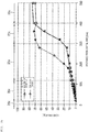
- Fig. 3A is a graph showing flexural load values of the core wire 20 of the guide wire 10 along the axial direction position of the core wire 20
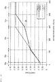
- Fig. 3B is a graph showing diameters of the core wire 20 of the guide wire 10 along the axial direction position of the core wire 20.
- the core wire 20 has a flexibility, and has the distal core portion 34, the main body portion 30, and the rigidity changing portion 35. Including a foremost distal end, the distal core portion 34 is the most flexible site in the entire length of the core wire 20.
- the main body portion 30 constitutes a portion more proximal than the distal core portion 34 and is a site having a constant diameter d0 along the axial direction.
- the rigidity changing portion 35 constitutes a portion from the distal end of the main body portion 30 to the proximal end of the distal core portion 34, and is a site that gradually decreases in rigidity from the main body portion 30 toward the distal core portion 34.
- the rigidity changing portion 35 includes at least the first tapered portion 31, the second tapered portion 32,..., the (n-1) th tapered portion, and the n-th tapered portion 33 (where, n ⁇ 3), in order from the proximal side to the distal side.
- Each of the tapered portions 31, 32, ..., 33 has a tapered shape that gradually decreases in diameter (inclined to the axial direction).
- the n-th tapered portion 33 is hereinafter referred to as a "third tapered portion 33".
- a region of the distal core portion 34 is indicated by a reference numeral 34a
- a region of the main body portion 30 is indicated by a reference numeral 30a.
- a region of the first tapered portion 31 is indicated by a reference numeral 31a
- a region of the second tapered portion 32 is indicated by a reference numeral 32a
- a region of the third tapered portion 33 is indicated by a reference numeral 33a.
- the core wire 20 is formed of a single material.
- the diameter of the core wire 20 varies along the axial direction. Thereby, the rigidity of the core wire 20 changes along the axial direction.
- the constituent material of the core wire 20 is not particularly limited, and, for example, a Ni-Ti based alloy, a stainless steel, a super-elastic alloy or the like can be used.
- the main body portion 30 has a constant diameter d0 along the axial direction.
- the distal core portion 34 also has a constant diameter d4 along the axial direction.
- the first tapered portion 31 is continuous with the distal end of the main body portion 30 and has a diameter d1 that gradually decreases from the main body portion 30 toward the distal core portion 34.
- the second tapered portion 32 is continuous with the distal end of the first tapered portion 31 and has a diameter d2 that gradually decreases from the first tapered portion 31 toward the distal core portion 34.
- the third tapered portion 33 is continuous with the proximal end of the distal core portion 34, and has a diameter d3 that gradually decreases from the second tapered portion 32 continuous with the proximal side, toward the distal core portion 34.
- the boundary portion 36 between the first tapered portion 31 and the second tapered portion 32 is preferably located within a range of 300 to 400 mm from the foremost distal end of the distal core portion 34. Furthermore, it is preferable that the gradient ((d12 - d11)/L1) of the change in the diameter d1 in the first tapered portion 31 is larger than the gradient ((d22 - d21)/L2) of the change in the diameter d2 in the second tapered portion 32. As shown in Fig. 3B , in the present embodiment, the boundary portion 36 is set at a position of 300 mm from the foremost distal end of the distal core portion 34.
- the flexural load values and the diameters in the core wire of the contrast example are indicated by broken lines.
- the length of the rigidity changing portion is 280 mm, and the start point of the proximal side of the rigidity changing portion is 300 mm from the foremost distal end.
- a range of the rigidity changing portion in the core wire is up to 300 mm from the foremost distal end of the core wire.
- the range of the rigidity changing portion 35 in the core wire 20 is longer toward the proximal side beyond 300 mm from the foremost distal end of the core wire 20.
- the gradient ((d12 - d11)/L1) of the change in the diameter d1 in the first tapered portion 31 is larger than the gradient ((d22 - d21)/L2) of the change in the diameter d2 in the second tapered portion 32. From this, as shown in Fig. 3A , in a unit length in the axial direction, the decrease in the rigidity in the first tapered portion 31 is larger than the decrease in the rigidity in the second tapered portion 32. As a result, the range having a relatively small rigidity expands in the axial direction as much as possible.
- the axial direction length of the rigidity changing portion 35 becomes longer without structural modification (change in diameter, material, or the like) of the distal core portion 34 and the third tapered portion 33 continuous with the proximal end of the distal core portion 34.
- the distal core portion 34 and the third tapered portion 33 constitute the distal part of the core wire 20, and are sites that greatly affect the flexibility and usability of the guide wire 10. Therefore, even if the axial direction length of the rigidity changing portion 35 is changed, an occurrence of discomfort in usability by the operator is small.
- the axial direction length of the distal core portion 34 is 20 mm, and the length of the rigidity changing portion of the contrast example is 280 mm as described above.
- the third tapered portion 33 continuous with the proximal side of the distal core portion 34 has substantially the same change in the flexural load values along the axial direction as the core wire in which the range of rigidity changing portion is up to 300 mm from the foremost distal end of the distal core portion (core wire of the contrast example) .
- the change in the flexural load values along the axial direction greatly affects the flexibility and usability of the guide wire 10, as described above, even if the axial direction length of the rigidity changing portion 35 is changed, an occurrence of discomfort in usability by the operator is small.
- the ratio of the gradients ( ⁇ n/ ⁇ 0) is not limited to approximately one, and can be freely set within a range that does not cause a sense of discomfort in the usability by the operator. From this point of view, it is preferable that the ratio of gradients ( ⁇ n/ ⁇ 0) be 0.27 ⁇ ⁇ n/ ⁇ 0 ⁇ 1.80. If the ratio of the gradients ( ⁇ n/ ⁇ 0) is less than 0.27, the change in the rigidity of the core wire 20 is poor, so that an unintended deviation in the guide wire 10 position is likely to occur. If the ratio of the gradients ( ⁇ n/ ⁇ 0) exceeds 1.80, the change in rigidity of the core wire 20 is too large, and the operability of the guide wire 10 is reduced. Therefore, the above range is preferable.
- the diameter d12 of the proximal side of the first tapered portion 31 is substantially the same as the diameter d0 of the main body portion 30 so that the boundary between the main body portion 30 and the first tapered portion 31 is a continuous surface.
- the diameter d22 of the proximal side of the second tapered portion 32 is substantially the same as the diameter d11 of the distal side of the first tapered portion 31.
- the diameter d32 of the proximal side of the third tapered portion 33 is substantially the same as the diameter d21 of the distal side of the second tapered portion 32.
- the diameter d4 of the distal core portion 34 is substantially the same as the diameter d31 of the distal side of the third tapered portion 33.
- continuous surface means that an outer surface of the core wire 20 is smooth to the extent that the guide wire 10 does not get caught on an inner wall of the body lumen or the catheter 60.
- a coating layer 50 the outer surface of the guide wire 10 may be a substantially smooth surface, and the guide wire 10 may not be caught by the inner wall of the body lumen or the like. In such a case, even if the core wire 20 has a slight level difference, the outer surface of the core wire 20 can be regarded as a "continuous surface".
- a tapered angle (inclination angle to the axial direction of a tapered shape) of the first tapered portion 31 is constant along the axial direction.
- the tapered angle of the second tapered portion 32 is constant along the axial direction.
- the tapered angle of the third tapered portion 33 is constant along the axial direction.
- each tapered portion 31, 32, and 33 can be changed along the axial direction.
- the tapered angle can be changed so that a central part bulges outward in a convex shape with respect to a linear shape when the tapered angle is constant.
- any combination may be made, for example, in such a manner that the tapered angles of the first tapered portion 31 and the third tapered portion 33 are constant along the axial direction and the tapered angle of the second tapered portion 32 is changed along the axial direction.
- the core wire 20 is formed by performing a cutting process or a polishing process for a forming material.
- the respective regions of the main body portion 30, the first tapered portion 31, the second tapered portion 32, the third tapered portion 33, and the distal core portion 34 can be simultaneously formed. Respective regions may be formed separately and sequentially.
- the manufacture of the core wire 20 is not limited to the cutting process or the polishing process, and can be formed by an etching or a laser process.
- each tapered portion 31, 32, and 33 can be formed more easily as compared with a case where the tapered angle is changed along the axial direction.
- the gradient ((d12 - d11)/L1) of the change in the diameter d1 in the first tapered portion 31 is larger than the gradient ((d22 - d21)/L2) of the change in the diameter d2 in the second tapered portion 32.
- the diameter d11 of the distal side in the first tapered portion 31 is 45% to 75% of the diameter d0 of the main body portion 30. In the example of Table 1, 0.275/0.400 ⁇ 0.688. If the diameter d11 is less than 45% of the diameter d0, the core wire 20 becomes too soft, and the operability of the guide wire 10 is reduced.
- the gradient ((d12 - d11)/L1) of the change in the diameter d1 in the first tapered portion 31 is 3.4 to 21.7 times the gradient ((d22 - d21)/L2) of the change in the diameter d2 in the second tapered portion 32.
- the gradient ((d12 - d11)/L1) of the change in the diameter d1 in the first tapered portion 31 is 3.4 to 21.7 times the gradient ((d22 - d21)/L2) of the change in the diameter d2 in the second tapered portion 32.
- the change in the diameter d1 is less than 3.4 times the gradient of the change in the diameter d2, the change in the rigidity of the core wire 20 is poor, so that an unintended deviation in the guide wire 10 position is likely to occur. If the gradient of the change in the diameter d1 exceeds 21.7 times the gradient of the change in the diameter d2, the change in rigidity of the core wire 20 is too large, and the operability of the guide wire 10 is reduced. Therefore, the above range is preferable. (3) It is preferable that the change (d12 - d21) in diameter in the first tapered portion 31 and the second tapered portion 32 is 1.4 to 7.1 times the change (d32 - d31) in the diameter in the third tapered portion 33.
- Fig. 4 is a cross-sectional diagram showing a schematic configuration of a measurement test device 200 for measuring a flexural load value of the core wire 20 of the guide wire 10.
- the measurement test device 200 has a fixing jig 201 for supporting the core wire 20 and a pushing-down jig 202 disposed above the fixing jig 201.
- the fixing jig 201 has a pair of supporting legs 203 for supporting the core wire 20 at two points.
- the interval Ld between the supporting legs 203 is 25.4 mm.
- the pushing-down jig 202 is configured to be freely movable in an up-and-down manner with respect to the fixing jig 201.
- the pushing-down jig 202 is configured to freely adjust the speed at which the core wire 20 is pushed down and the dimension at which the core wire 20 is pushed down.
- a flexural load value measurement is performed under the following conditions to obtain a flexural load value. That is, the core wire 20 is supported at two points with 25.4 mm gap.
- the pushing-down jig 202 moves at a speed of 5 mm/min.
- the supported central part of the core wire 20 is vertically pushed down by the pushing-down jig 202.
- the flexural load value is obtained by measuring the load when the core wire 20 is pushed down by 2 mm. Since it is necessary to support the core wire 20 at two points, the measurement of the flexural load value is started from a position 20 mm from the foremost distal end of the core wire 20.
- the measurement start position is a position of the distal end of the third tapered portion 33.
- Fig. 3A measurement values from a position 20 mm from the foremost distal end of the core wire 20 are plotted.
- One example of flexural load values of the main body portion 30, the first tapered portion 31, the second tapered portion 32, and the third tapered portion 33 is as shown in Table 2 below.
- a load value at this position is referred to as "flexural load value near distal end f31".
- a length is 100 mm which is a measureable range.
- any of the following (4) to (6) can be said.
- a flexural load value obtained by the flexural load value measurement it is preferable that a flexural load value f11 of the distal side in the first tapered portion 31 is 13% to 36% of a flexural load value f0 of the main body portion 30. In the example of Table 2, 25.2/79.8 ⁇ 0.316.
- the flexural load value f11 is less than 13% of the flexural load value f0, the core wire 20 becomes too soft, and the operability of the guide wire 10 is reduced. If the flexural load value f11 exceeds 36% of the flexural load value f0, the rigidity of the core wire 20 is too high, so that an unintended deviation in the guide wire 10 position is likely to occur. Therefore, the above range is preferable.
- a gradient ((f12 - f11)/L1) of the change in the flexural load value f1 in the first tapered portion 31 is 5.3 to 17.8 times the gradient ((f22 - f21)/L2) of the change in the flexural load value f2 in the second tapered portion 32.
- Table 2 0.55/0.10 ⁇ 5.5. If the gradient of the change in the flexural load value f1 is less than 5.3 times the gradient of the change in the flexural load value f2, the change in the rigidity of the core wire 20 is poor, so that an unintended deviation in the guide wire 10 position is likely to occur.
- the flexural load value f21 of the distal side in the second tapered portion 32 is 2.0 to 22.3 times the flexural load value f31 near the distal end in the third tapered portion 33
- the flexural load value f12 of the proximal side in the first tapered portion 31 is 187 to 239 times the flexural load value f31 near the distal end of the third tapered portion 33.
- f21/f31 is less than 2.0 times, the change in the rigidity of the core wire 20 is poor, so that an unintended deviation in the guide wire 10 position is likely to occur. If f21/f31 exceeds 22.3 times, the change in rigidity of the core wire 20 is too large, and the operability of the guide wire 10 is reduced. Further, if f12/f31 is less than 187 times, the rigidity of the distal core portion 34 is high, and the risk of vascular damage increases. If f12/f31 exceeds 239 times, the change in rigidity of the core wire 20 is too large, and the operability of the guide wire 10 is reduced. Therefore, the above range is preferable.
- the axial direction length of the core wire 20 has a length suitable for use in the TACE.
- the axial direction length L (L1 + L2 + L3) of the rigidity changing portion 35 is preferably 360 to 430 mm or 360 to 400 mm.
- the boundary portion 36 between the first tapered portion 31 and the second tapered portion 32 is in a range of 200 to 400 mm from the distal end of the distal core portion 34, more preferably in a range of 250 to 350 mm from the distal end of the distal core portion 34, and still more preferably, it is located in a range of 280 to 320 mm from the distal end of the distal core portion 34.
- the axial direction length L1 of the first tapered portion 31 is 80 to 230 mm, more preferably 80 to 170 mm, still more preferably 80 to 120 mm, and 100 mm is particularly preferable.
- the region of the core wire 20 reaching the site from the aorta to the common hepatic artery (300 to 400 mm from the distal end) becomes flexible, thereby the TACE can be suitably performed.
- the axial direction length L2 of the second tapered portion 32 is 160 to 280 mm, more preferably 160 to 220 mm, still more preferably 160 to 200 mm, and 180 mm is particularly preferable.
- the region of the core wire 20 reaching the site from the common hepatic artery to the proper hepatic artery and further to the left and right hepatic artery (100 to 300 from the distal end) becomes flexible, thereby the TACE can be suitably performed.
- the position of the boundary portion 36 between the first tapered portion 31 and the second tapered portion 32 described above, the length of the first tapered portion 31, and the length of the second tapered portion 32 are based on sensory test results when the TACE is performed using a model that simulates the liver 90.
- a marker portion 40 is disposed to cover the distal core portion 34 in a certain range extending in the axial direction.
- the marker portion 40 is configured with a wire wound in a spiral shape around the distal core portion 34.
- the distal portion of the marker portion 40 is fixed near the distal portion of the distal core portion 34 through the fixing material 41.
- the proximal portion of the marker portion 40 is fixed near the proximal portion of the distal core portion 34 through the fixing material 42.
- the fixing materials 41 and 42 can be made of, for example, various adhesives, solder, or the like.
- the marker portion 40 is made of a material having radiopacity (radiopaque property).
- a material having the radiopacity include metal materials such as noble metals such as gold, platinum, tungsten or alloys containing noble metals (for example, platinum-iridium alloy).
- the coating layer 50 is made of a resin material and formed so as to cover the entire core wire 20 including the marker portion 40.
- the distal portion of the coating layer 50 is preferably a rounded shape so as not to damage the inner wall of the body lumen.
- the coating layer 50 is preferably made of a material that can reduce friction. Thereby, the frictional resistance (sliding resistance) with the catheter 60 through which the guide wire 10 is inserted or the body lumen is reduced and the sliding performance is improved, and the operability of the guide wire 10 can be improved. Further, since the sliding resistance of the guide wire 10 is reduced, it is possible to more reliably prevent kinks (bend) or twists of the guide wire 10.
- the resin material constituting the coating layer 50 is preferably a material having relatively high flexibility, for example, polyolefin such as polyethylene and polypropylene, polyvinyl chloride, polyester (PET, PBT, or the like), polyamide, polyimide, polyurethane, polystyrene, polycarbonate, silicone resins, fluorine-based resins (PTFE, ETFE, PFA, or the like), composite materials thereof, various rubber materials such as latex rubber and silicone rubber, or composite materials obtained by combining two or more in these which is mentioned above.
- polyolefin such as polyethylene and polypropylene
- polyvinyl chloride polyester (PET, PBT, or the like)
- composite materials thereof various rubber materials such as latex rubber and silicone rubber, or composite materials obtained by combining two or more in these which is
- the thickness of the coating layer 50 is not particularly limited, and is preferably, for example, 5 to 500 ⁇ m. Note that the coating layer 50 is not limited to a single layer structure, and may be configured by laminating a plurality of layers.
- the coating layer 50 is preferably covered with a hydrophilic coating layer not shown. Since the sliding performance is improved by being covered by the hydrophilic coating layer, the guide wire 10 can be further prevented from being caught on the inner wall of the body lumen or the catheter 60.
- the constituent material of the hydrophilic coating layer is not particularly limited, and for example, well-known hydrophilic substances may be mentioned, such as a cellulose-based polymer substance, polyethylene oxide polymer substance, maleic anhydride-based polymer substance (for example, maleic anhydride copolymer such as methyl vinyl ether-maleic anhydride copolymer), acrylamide-based polymer substance (for example, block copolymers of polyacrylamide, polyglycidyl methacrylate-dimethyl acrylamide (PGMA-DMAA)), water soluble nylon, polyvinyl alcohol, and polyvinyl pyrrolidone.
- hydrophilic substances such as a cellulose-based polymer substance, polyethylene oxide polymer substance, maleic anhydride-based polymer substance (for example, maleic anhydride copolymer such as methyl vinyl ether-maleic anhydride copolymer), acrylamide-based polymer substance (for example, block copolymers of polyacrylamide, polyglycidyl
- the thickness of the hydrophilic coating layer is not particularly limited, and is preferably, for example, 0.1 to 100 ⁇ m.
- the guide wire 10 of the present embodiment has the following actions and effects.
- the core wire 20 in the guide wire 10 arranges the boundary portion 36 between the first tapered portion 31 and the second tapered portion 32 in a range of 300 to 400 mm from the foremost distal end of the distal core portion 34, and sets a gradient d1 ((d12 - d11)/L1) of the change in the diameter d1 in the first tapered portion 31 larger than a gradient ((d22 - d21)/L2) of the change in the diameter d2 in the second tapered portion 32.
- the range of the rigidity changing portion 35 in the core wire 20 is longer toward the proximal side beyond 300 mm from the foremost distal end of the core wire 20.
- the gradient ((d12 - d11)/L1) of the change in the diameter d1 in the first tapered portion 31 is larger than the gradient ((d22 - d21) /L2) of the change in the diameter d2 in the second tapered portion 32. Therefore, in a unit length in the axial direction, the decrease in the rigidity in the first tapered portion 31 is larger than the decrease in the rigidity in the second tapered portion 32.
- the range having a relatively small rigidity expands in the axial direction as much as possible. Therefore, as in TACE, even when the fixing state of the guide wire 10 is loosened in a case of performing a procedure in which the target site of treatment is present in the deep side of the body lumen, an unintended deviation in the guide wire 10 position is reduced. Furthermore, the axial direction length of the rigidity changing portion 35 becomes longer without structural modification of the distal core portion 34 and the third tapered portion 33 continuous with the proximal end of the distal core portion 34.
- the distal core portion 34 and the third tapered portion 33 constitute the distal part of the core wire 20, and are sites that greatly affect the flexibility and usability of the guide wire 10. Therefore, according to the present embodiment, it is possible to provide a guide wire 10 capable of reducing an unintended deviation in a guide wire 10 position while preventing an occurrence of discomfort with respect to usability.
- the change in the flexural load value along the axial direction greatly affects the flexibility and usability of the guide wire 10.
- the change in the flexural load value along the axial direction in the vicinity of the distal end is substantially the same as when the length of the rigidity changing portion is 300 mm.
- discomfort does not occur in usability. Therefore, it is possible to provide a guide wire 10 capable of reducing an unintended deviation in a guide wire 10 position while preventing an occurrence of discomfort with respect to usability.
- the core wire 20 is formed of a single material.
- the core wire 20 can be easily manufactured as compared with a case where the distal core portion 34, the rigidity changing portion 35, and the main body portion 30 are formed of different materials and joined.
- the tapered angle of the first tapered portion 31 is constant along the axial direction.
- the first tapered portion 31 can be easily formed as compared with a case where the tapered angle is changed along the axial direction.
- the tapered angle of the second tapered portion 32 is constant along the axial direction.
- the second tapered portion 32 can be easily formed as compared with a case where the tapered angle is changed along the axial direction.
- the tapered angle of the third tapered portion 33 is constant along the axial direction.
- the third tapered portion 33 can be easily formed as compared with a case where the tapered angle is changed along the axial direction.
- the core wire 20 has a length suitable for use in the TACE.
- the axial direction length L of the rigidity changing portion 35 is 360 to 430 mm.
- the region of the core wire 20 reaching the site (300 to 400 mm from the distal end) from the aorta to the proper hepatic artery becomes flexible, thereby it is possible to reduce an unintended deviation in the guide wire 10 position while preventing an occurrence of discomfort in usability.
- the axial direction length L of the rigidity changing portion 35 is set to 360 to 430 mm
- the axial direction length L1 of the first tapered portion 31 is 80 to 230 mm.
- the TACE can be more suitably performed.
- the axial direction length L of the rigidity changing portion 35 is set to 360 to 430 mm
- the axial direction length L2 of the second tapered portion 32 is 160 to 280 mm.
- the TACE can be more suitably performed.
- the guide wire 10 used for the TACE has been mentioned as an example, the guide wire 10 of the present invention can be used in other procedures.
- the rigidity changing portion 35 may be configured with four or more tapered portions.
- the present invention is not limited to the case.
- a plurality of rigidity changing portions 35, and the distal core portion 34 By using different materials for each constituent material of the main body portion 30, a plurality of rigidity changing portions 35, and the distal core portion 34, the rigidity can be changed along the axial direction.
- the main body portion 30, the plurality of rigidity changing portions 35, and the distal core portion 34 which are using different constituent materials can be joined by an appropriate known method such as welding, deposition, or adhesion.
- Each portion of the core wire 20 may be formed by combining the use of different constituent materials and the forming in a tapered shape.
Landscapes
- Health & Medical Sciences (AREA)
- Life Sciences & Earth Sciences (AREA)
- Surgery (AREA)
- Veterinary Medicine (AREA)
- Public Health (AREA)
- General Health & Medical Sciences (AREA)
- Engineering & Computer Science (AREA)
- Biomedical Technology (AREA)
- Heart & Thoracic Surgery (AREA)
- Animal Behavior & Ethology (AREA)
- Molecular Biology (AREA)
- Medical Informatics (AREA)
- Nuclear Medicine, Radiotherapy & Molecular Imaging (AREA)
- Vascular Medicine (AREA)
- Reproductive Health (AREA)
- Biophysics (AREA)
- Pulmonology (AREA)
- Anesthesiology (AREA)
- Hematology (AREA)
- Media Introduction/Drainage Providing Device (AREA)
Abstract
Description
- The present invention relates to a guide wire.
- In the related art, a catheter device is used to perform a treatment or the like in a body lumen. A guide wire having a flexible core wire is used to guide the catheter device to a target site of the body lumen. For example, a transe catheter arterial chemo embolization (TACE) is a treatment method in which a catheter is advanced from an artery of the liver further to the vicinity of a tumor, and an anti-cancer agent or an embolic material is injected to selectively necrosis the tumor. In the TACE, a guide wire is used to advance the catheter.
- In order to enhance operability when passing a guide wire into a body lumen, there is known a guide wire provided with a rigidity changing portion that gradually decreases in rigidity from a proximal side toward a distal side (for example, see PTL 1). The rigidity of the rigidity changing portion is changed by gradually decreasing a diameter of a core wire. Note that the "proximal side" means a side located on an opposite side, when a side introduced into the living body is referred to as a "distal side".
- PTL 1:
U.S. Patent No. 5865767 - A body lumen has an intricately curved or serpentine shape. Therefore, when a guide wire passes through the body lumen, a large bending load acts on the core wire as a distal portion of the guide wire reaches the deep side.
- In the related art of the guide wire, the range in which the rigidity changing portion of the core wire is provided is a range of at most 300 mm from a foremost distal end of the core wire. Therefore, in a case of the procedure in which a target site of treatment is present in the deep side of the body lumen, a large bending load acts on the core wire. The restoring force to return to the original straight state acts on the bent core wire. As a result, when a fixed state of the guide wire is loosened, a position of the guide wire is deviated in a direction to get out of the body. Thus, an unintended deviation in guide wire position can easily occur.
- In order to reduce the unintended deviation in guide wire position, it is conceivable to widen a range in which the rigidity changing portion is provided in the core wire toward the proximal side. However, merely widening the range of the rigidity changing portion causes a sense of discomfort in usability by an operator.
- An object of the present invention is to provide a guide wire which is capable of reducing an unintended deviation in a guide wire position while preventing an occurrence of discomfort with respect to usability.
- A guide wire according to the present invention includes a flexible core wire, in which the core wire has a distal core portion that includes a foremost distal end and is most flexible in an entire length of the core wire, a main body portion that constitutes a portion more proximal than the distal core portion and has a constant diameter along an axial direction, and a rigidity changing portion that constitutes a portion from a distal end of the main body portion to a proximal end of the distal core portion and gradually decreases in rigidity from the main body portion toward the distal core portion. The rigidity changing portion includes at least a first tapered portion that is continuous with the distal end of the main body portion and has a diameter gradually decreasing from the main body portion toward the distal core portion, a second tapered portion that is continuous with a distal end of the first tapered portion and has a diameter gradually decreasing from the first tapered portion toward the distal core portion, and an n-th tapered portion that is continuous with the proximal end of the distal core portion and has a diameter (dn) gradually decreasing from an (n-1) th tapered portion being continuous with the proximal side toward the distal core portion (wherein, n ≥ 3). Further, a boundary portion between the first tapered portion and the second tapered portion is located in a range of 300 to 400 mm from the foremost distal end of the distal core portion, and a gradient ((d12 - d11)/L1) of a change in the diameter (d1) in the first tapered portion is larger than a gradient ((d22 - d21) /L2) of a change in the diameter (d2) in the second tapered portion.
- By a first tapered portion and a second tapered portion in a rigidity changing portion, a range of the rigidity changing portion in a core wire is longer toward a proximal side beyond 300 mm from the foremost distal end of the core wire. The gradient of a change in a diameter in the first tapered portion is larger than a gradient of a change in a diameter in the second tapered portion. Therefore, in a unit length in an axial direction, the decrease in the rigidity in the first tapered portion is larger than the decrease in the rigidity in the second tapered portion. As a result, the range having a relatively small rigidity expands in the axial direction as much as possible. Therefore, as in TACE, even when a fixing state of the guide wire is loosened in a case of performing a procedure in which the target site of treatment is present in the deep side of the body lumen, an unintended deviation in the guide wire position is reduced. Furthermore, the axial direction length of the rigidity changing portion becomes longer without structural modification of the distal core portion and the n-th tapered portion continuous with the proximal end of the distal core portion. The distal core portion and the n-th tapered portion constitute the distal part of the core wire, and are sites that greatly affect the flexibility and usability of the guide wire. Therefore, according to the present invention, it is possible to provide a guide wire which is capable of reducing an unintended deviation in a guide wire position while preventing an occurrence of discomfort with respect to usability.
-
- [
Fig. 1A] Fig. 1A is an axial direction cross-sectional diagram of a guide wire. - [
Fig. 1B] Fig. 1B is an axial direction cross-sectional diagram showing a distal part of the guide wire in an enlarged manner. - [
Fig. 2] Fig. 2 is a diagram schematically showing an aspect in which a catheter is being advanced along the guide wire in a TACE. - [
Fig. 3A] Fig. 3A is a graph showing flexural load values of a core wire of the guide wire along an axial position of the core wire. - [
Fig. 3B] Fig. 3B is a graph showing diameters of the core wire of the guide wire along the axial position of the core wire. - [
Fig. 4] Fig. 4 is a cross-sectional diagram showing a schematic configuration of a measurement test device for measuring a flexural load value of the core wire of the guide wire. - Hereinafter, an embodiment of the present invention will be described with reference to the attached drawings. Note that the following description does not limit the technical scope or the meaning of terms described in the claims. Further, the dimensional ratios in the drawings are exaggerated for the sake of explanation, and may differ from the actual proportions.
-
Fig. 1A is an axial direction cross-sectional diagram of aguide wire 10, andFig. 1B is an axial direction cross-sectional diagram showing a distal part of theguide wire 10 in an enlarged manner.Fig. 2 is a diagram schematically showing an aspect in which acatheter 60 is being advanced along theguide wire 10 in the TACE. - In the description of the present specification, a long-length direction (left and right direction in
Fig. 1A ) of thecore wire 20 of theguide wire 10 is defined as an axial direction, and is indicated by an arrow X in each drawing. A direction orthogonal to the axial direction is defined as a radial direction and is indicated by an arrow R inFig. 1B . - In the
guide wire 10, a side to be inserted into a living body (in the blood vessel) is defined as a distal side (distal side, left side inFig. 1A ) and is indicated by an arrow X1 in each drawing, and a side to be operated at the hand located opposite to the distal side is defined as a proximal side (proximal side, right side inFig. 1A ) and is indicated by an arrow X2 in each drawing. In the present specification, a distal portion means a part including a certain range in the axial direction from the distal end (the foremost distal end), and a proximal portion means a part including a certain range in the axial direction from the proximal end (the foremost proximal end). - With regard to a diameter of the
core wire 20, numbers (1, 2, 3) of the suffix "x" represented as a diameter dxy represent a first taperedportion 31, a second taperedportion 32, and a thirdtapered portion 33, respectively. The numbers (1, 2) of the suffix "y" represent the distal side and the proximal side, respectively. With regard to a flexural load value of thecore wire 20, numbers (1, 2, 3) of the suffix "x" represented as a flexural load value fxy represent the first taperedportion 31, the second taperedportion 32, and the thirdtapered portion 33, respectively. The numbers (1, 2) of the suffix "y" represent the distal side and the proximal side, respectively. - Referring to
Figs. 1A and1B , theguide wire 10 of the present embodiment has thecore wire 20 extending in the axial direction, amarker portion 40 disposed at the distal portion of thecore wire 20, and acoating layer 50 coating thecore wire 20. - The
guide wire 10 is inserted into, for example, a body lumen. In the body lumen, theguide wire 10 is inserted through a lumen (guide wire lumen) of the therapeutic ordiagnostic catheter 60. Theguide wire 10 is used to guide thecatheter 60 to a target site of the body lumen. - For example, as shown in
Fig. 2 , the transe catheter arterial chemo embolization (TACE) is a treatment method in which thecatheter 60 is advanced from an artery 91 of theliver 90 further to the vicinity of atumor 92, and an anti-cancer agent or an embolic material is injected to selectively necrosis the tumor. In the TACE, theguide wire 10 is used to advance thecatheter 60. - A body lumen has an intricately curved or serpentine shape. Therefore, when the
guide wire 10 passes through the body lumen, a large bending load acts on thecore wire 20 as a distal portion of theguide wire 10 reaches the deep side. -
Fig. 3A is a graph showing flexural load values of thecore wire 20 of theguide wire 10 along the axial direction position of thecore wire 20, andFig. 3B is a graph showing diameters of thecore wire 20 of theguide wire 10 along the axial direction position of thecore wire 20. - As shown in
Figs. 1A and1B , thecore wire 20 has a flexibility, and has thedistal core portion 34, themain body portion 30, and therigidity changing portion 35. Including a foremost distal end, thedistal core portion 34 is the most flexible site in the entire length of thecore wire 20. Themain body portion 30 constitutes a portion more proximal than thedistal core portion 34 and is a site having a constant diameter d0 along the axial direction. Therigidity changing portion 35 constitutes a portion from the distal end of themain body portion 30 to the proximal end of thedistal core portion 34, and is a site that gradually decreases in rigidity from themain body portion 30 toward thedistal core portion 34. - The
rigidity changing portion 35 includes at least the first taperedportion 31, the second taperedportion 32,..., the (n-1) th tapered portion, and the n-th tapered portion 33 (where, n ≥ 3), in order from the proximal side to the distal side. Each of the taperedportions rigidity changing portion 35 includes three tapered portions (n = 3). Therefore, the second taperedportion 32 corresponds to the (n-1)th tapered portion. The n-th taperedportion 33 is hereinafter referred to as a "thirdtapered portion 33". - In
Figs. 3A and3B , a region of thedistal core portion 34 is indicated by areference numeral 34a, and a region of themain body portion 30 is indicated by areference numeral 30a. Further, a region of the first taperedportion 31 is indicated by areference numeral 31a, a region of the second taperedportion 32 is indicated by areference numeral 32a, and a region of the thirdtapered portion 33 is indicated by areference numeral 33a. - In the present embodiment, the
core wire 20 is formed of a single material. The diameter of thecore wire 20 varies along the axial direction. Thereby, the rigidity of thecore wire 20 changes along the axial direction. - The constituent material of the
core wire 20 is not particularly limited, and, for example, a Ni-Ti based alloy, a stainless steel, a super-elastic alloy or the like can be used. - The
main body portion 30 has a constant diameter d0 along the axial direction. Thedistal core portion 34 also has a constant diameter d4 along the axial direction. - In the present specification, "having a constant diameter along the axial direction" does not mean to be limited to a case of physically having the same diameter. In a range in which the rigidity (flexural rigidity or torsional rigidity) of the
main body portion 30 or thedistal core portion 34 can be made substantially constant, it is sufficient to have a substantially constant outer diameter dimension. - The first tapered
portion 31 is continuous with the distal end of themain body portion 30 and has a diameter d1 that gradually decreases from themain body portion 30 toward thedistal core portion 34. The second taperedportion 32 is continuous with the distal end of the first taperedportion 31 and has a diameter d2 that gradually decreases from the first taperedportion 31 toward thedistal core portion 34. The thirdtapered portion 33 is continuous with the proximal end of thedistal core portion 34, and has a diameter d3 that gradually decreases from the second taperedportion 32 continuous with the proximal side, toward thedistal core portion 34. - The
boundary portion 36 between the first taperedportion 31 and the second taperedportion 32 is preferably located within a range of 300 to 400 mm from the foremost distal end of thedistal core portion 34. Furthermore, it is preferable that the gradient ((d12 - d11)/L1) of the change in the diameter d1 in the first taperedportion 31 is larger than the gradient ((d22 - d21)/L2) of the change in the diameter d2 in the second taperedportion 32. As shown inFig. 3B , in the present embodiment, theboundary portion 36 is set at a position of 300 mm from the foremost distal end of thedistal core portion 34. - In
Figs. 3A and3B , the flexural load values and the diameters in the core wire of the contrast example are indicated by broken lines. In the contrast example, the length of the rigidity changing portion is 280 mm, and the start point of the proximal side of the rigidity changing portion is 300 mm from the foremost distal end. - As shown in
Fig. 3B , in the contrast example, a range of the rigidity changing portion in the core wire is up to 300 mm from the foremost distal end of the core wire. On the other hand, in the present embodiment, by the first taperedportion 31 and the second taperedportion 32 in therigidity changing portion 35, the range of therigidity changing portion 35 in thecore wire 20 is longer toward the proximal side beyond 300 mm from the foremost distal end of thecore wire 20. - The gradient ((d12 - d11)/L1) of the change in the diameter d1 in the first tapered
portion 31 is larger than the gradient ((d22 - d21)/L2) of the change in the diameter d2 in the second taperedportion 32. From this, as shown inFig. 3A , in a unit length in the axial direction, the decrease in the rigidity in the first taperedportion 31 is larger than the decrease in the rigidity in the second taperedportion 32. As a result, the range having a relatively small rigidity expands in the axial direction as much as possible. - Furthermore, the axial direction length of the
rigidity changing portion 35 becomes longer without structural modification (change in diameter, material, or the like) of thedistal core portion 34 and the thirdtapered portion 33 continuous with the proximal end of thedistal core portion 34. Thedistal core portion 34 and the thirdtapered portion 33 constitute the distal part of thecore wire 20, and are sites that greatly affect the flexibility and usability of theguide wire 10. Therefore, even if the axial direction length of therigidity changing portion 35 is changed, an occurrence of discomfort in usability by the operator is small. - As shown in
Fig. 3B , the gradient Δ3 (= (d32 - d31)/L3) of the change in the diameter d3 in the thirdtapered portion 33 of the present embodiment is substantially the same as the gradient of the change in the diameter in the rigidity changing portion in the contrast example. In other words, the gradient Δn (= (dn2 - dn1)/Ln) of the change in the diameter dn in the n-th tapered portion is substantially the same with respect to the gradient Δ0 (= (d0 - d4) / (300 - axial direction length of the distal core portion)) of the change in the diameter determined by the distal end diameter d0 of the main body portion and the proximal end diameter d4 of the distal core portion when the range of the rigidity changing portion is up to 300 mm from the foremost distal end of the distal core portion. The axial direction length of thedistal core portion 34 is 20 mm, and the length of the rigidity changing portion of the contrast example is 280 mm as described above. - As shown in
Fig. 3A , the thirdtapered portion 33 continuous with the proximal side of thedistal core portion 34 has substantially the same change in the flexural load values along the axial direction as the core wire in which the range of rigidity changing portion is up to 300 mm from the foremost distal end of the distal core portion (core wire of the contrast example) . As the change in the flexural load values along the axial direction greatly affects the flexibility and usability of theguide wire 10, as described above, even if the axial direction length of therigidity changing portion 35 is changed, an occurrence of discomfort in usability by the operator is small. - The ratio of the gradients (Δn/Δ0) is not limited to approximately one, and can be freely set within a range that does not cause a sense of discomfort in the usability by the operator. From this point of view, it is preferable that the ratio of gradients (Δn/Δ0) be 0.27 ≤ Δn/Δ0 ≤ 1.80. If the ratio of the gradients (Δn/Δ0) is less than 0.27, the change in the rigidity of the
core wire 20 is poor, so that an unintended deviation in theguide wire 10 position is likely to occur. If the ratio of the gradients (Δn/Δ0) exceeds 1.80, the change in rigidity of thecore wire 20 is too large, and the operability of theguide wire 10 is reduced. Therefore, the above range is preferable. - The diameter d12 of the proximal side of the first tapered
portion 31 is substantially the same as the diameter d0 of themain body portion 30 so that the boundary between themain body portion 30 and the first taperedportion 31 is a continuous surface. Similarly, the diameter d22 of the proximal side of the second taperedportion 32 is substantially the same as the diameter d11 of the distal side of the first taperedportion 31. The diameter d32 of the proximal side of the thirdtapered portion 33 is substantially the same as the diameter d21 of the distal side of the second taperedportion 32. The diameter d4 of thedistal core portion 34 is substantially the same as the diameter d31 of the distal side of the thirdtapered portion 33. - In the present specification, "continuous surface" means that an outer surface of the
core wire 20 is smooth to the extent that theguide wire 10 does not get caught on an inner wall of the body lumen or thecatheter 60. For example, when the diameter d12 of the proximal side of the first taperedportion 31 and the diameter d0 of themain body portion 30 are not formed substantially the same, a slight level difference is generated at the boundary between the first taperedportion 31 and themain body portion 30. However, by acoating layer 50, the outer surface of theguide wire 10 may be a substantially smooth surface, and theguide wire 10 may not be caught by the inner wall of the body lumen or the like. In such a case, even if thecore wire 20 has a slight level difference, the outer surface of thecore wire 20 can be regarded as a "continuous surface". - A tapered angle (inclination angle to the axial direction of a tapered shape) of the first tapered
portion 31 is constant along the axial direction. The tapered angle of the second taperedportion 32 is constant along the axial direction. The tapered angle of the thirdtapered portion 33 is constant along the axial direction. - Note that the tapered angle of each tapered
portion - Any combination may be made, for example, in such a manner that the tapered angles of the first tapered
portion 31 and the thirdtapered portion 33 are constant along the axial direction and the tapered angle of the second taperedportion 32 is changed along the axial direction. - The
core wire 20 is formed by performing a cutting process or a polishing process for a forming material. The respective regions of themain body portion 30, the first taperedportion 31, the second taperedportion 32, the thirdtapered portion 33, and thedistal core portion 34 can be simultaneously formed. Respective regions may be formed separately and sequentially. The manufacture of thecore wire 20 is not limited to the cutting process or the polishing process, and can be formed by an etching or a laser process. - When the tapered angle is made constant along the axial direction, each tapered
portion - One example of dimensional specifications of the
main body portion 30, the first taperedportion 31, the second taperedportion 32, the thirdtapered portion 33, and thedistal core portion 34 is as shown in Table 1 below.[Table 1] Region Diameter [mm] Axial Length [mm] Gradient of Change in Diameter (Diameter Variation/Length) Distal core portion 34Diameter d4: 0.080 L4=20 - Third tapered portion 33Distal side diameter d31 (=d4) L3=100 0.0013 Proximal side diameter d32: 0.210 Second tapered portion 32Distal side diameter d21 (=d32) L2=180 0.000361 Proximal side diameter d22: 0.275 First tapered portion 31Distal side diameter d11 (=d22) L1=100 0.00125 Proximal side diameter d12 (=d0) Main body portion 30Diameter d0: 0.400 (Depending on product length) - - Referring to
Fig. 3B and Table 1, the gradient ((d12 - d11)/L1) of the change in the diameter d1 in the first taperedportion 31 is larger than the gradient ((d22 - d21)/L2) of the change in the diameter d2 in the second taperedportion 32. - Regarding the diameters d1, d2, and d3 of the respective
tapered portions
(1) It is preferable that the diameter d11 of the distal side in the first taperedportion 31 is 45% to 75% of the diameter d0 of themain body portion 30. In the example of Table 1, 0.275/0.400 ≈ 0.688. If the diameter d11 is less than 45% of the diameter d0, thecore wire 20 becomes too soft, and the operability of theguide wire 10 is reduced. If the diameter d11 exceeds 75% of the diameter d0, the rigidity of thecore wire 20 is too high, so that an unintended deviation in theguide wire 10 position is likely to occur when the fixed state of theguide wire 10 is loosened. Therefore, the above range is preferable.
(2) It is preferable that the gradient ((d12 - d11)/L1) of the change in the diameter d1 in the first taperedportion 31 is 3.4 to 21.7 times the gradient ((d22 - d21)/L2) of the change in the diameter d2 in the second taperedportion 32. In the example of Table 1, 0.00125/0.000361 ≈ 3.46. If the gradient of the change in the diameter d1 is less than 3.4 times the gradient of the change in the diameter d2, the change in the rigidity of thecore wire 20 is poor, so that an unintended deviation in theguide wire 10 position is likely to occur. If the gradient of the change in the diameter d1 exceeds 21.7 times the gradient of the change in the diameter d2, the change in rigidity of thecore wire 20 is too large, and the operability of theguide wire 10 is reduced. Therefore, the above range is preferable.
(3) It is preferable that the change (d12 - d21) in diameter in the first taperedportion 31 and the second taperedportion 32 is 1.4 to 7.1 times the change (d32 - d31) in the diameter in the thirdtapered portion 33. In the example of Table 1, (0.400 - 0.210)/(0.210 - 0.080) ≈ 1.46. If the change in diameter in the first taperedportion 31 and the second taperedportion 32 is less than 1.4 times the change in diameter in the thirdtapered portion 33, the change in the rigidity of thecore wire 20 is poor, so an unintended deviation in theguide wire 10 position is likely to occur. If the change in diameter in the first taperedportion 31 and the second taperedportion 32 exceeds 7.1 times the change in diameter in the thirdtapered portion 33, the rigidity change of thecore wire 20 is too large, and the operability of theguide wire 10 is reduced. Therefore, the above range is preferable.
The relationships of the above (1) to (3) based on the dimensional specifications of the respective regions are equivalent to the relationships based on the flexural load values. The flexural load value is obtained by a flexural load value measurement.
Fig. 4 is a cross-sectional diagram showing a schematic configuration of ameasurement test device 200 for measuring a flexural load value of thecore wire 20 of theguide wire 10.
Referring toFig. 4 , themeasurement test device 200 has a fixingjig 201 for supporting thecore wire 20 and a pushing-downjig 202 disposed above the fixingjig 201. The fixingjig 201 has a pair of supportinglegs 203 for supporting thecore wire 20 at two points. The interval Ld between the supportinglegs 203 is 25.4 mm. An upper surface of the supportinglegs 203 is formed with agroove portion 204 into which thecore wire 20 is fit. The pushing-downjig 202 is configured to be freely movable in an up-and-down manner with respect to the fixingjig 201. The pushing-downjig 202 is configured to freely adjust the speed at which thecore wire 20 is pushed down and the dimension at which thecore wire 20 is pushed down.
In the present embodiment, using themeasurement test device 200, a flexural load value measurement is performed under the following conditions to obtain a flexural load value. That is, thecore wire 20 is supported at two points with 25.4 mm gap. The pushing-downjig 202 moves at a speed of 5 mm/min. The supported central part of thecore wire 20 is vertically pushed down by the pushing-downjig 202. The flexural load value is obtained by measuring the load when thecore wire 20 is pushed down by 2 mm. Since it is necessary to support thecore wire 20 at two points, the measurement of the flexural load value is started from aposition 20 mm from the foremost distal end of thecore wire 20. The measurement start position is a position of the distal end of the thirdtapered portion 33. InFig. 3A , measurement values from aposition 20 mm from the foremost distal end of thecore wire 20 are plotted.
One example of flexural load values of themain body portion 30, the first taperedportion 31, the second taperedportion 32, and the thirdtapered portion 33 is as shown in Table 2 below.[Table 2] Region Flexural Load Value [gf] Position from Distal End [mm] Gradient of Change in Rigidity (Flexural Load Value Variation/Length) Third tapered portion 33Flexural load value near distal end f31: 0.4 20 (Note 1) 0.065 (Note 2) Flexural load value of proximal side f32: 6.9 120 Second tapered portion 32Flexural load value of distal side f21 (=f32) 120 0.10 Flexural load value of proximal side f22: 25.2 300 First tapered portion 31Flexural load value of distal side f11 (=f22) 300 0.55 Flexural load value of proximal side f12 (=f0) 400 Main body portion 30Flexural load value f0: 79.8 400 - (Note 1) It is a position of a distal end of a third tapered portion 33. A load value at this position is referred to as "flexural load value near distal end f31".
(Note 2) A length is 100 mm which is a measureable range.
Regarding the flexural load values f1, f2, and f3 of the respectivetapered portions
(4) Regarding the flexural load value obtained by the flexural load value measurement, it is preferable that a flexural load value f11 of the distal side in the first taperedportion 31 is 13% to 36% of a flexural load value f0 of themain body portion 30. In the example of Table 2, 25.2/79.8 ≈ 0.316. If the flexural load value f11 is less than 13% of the flexural load value f0, thecore wire 20 becomes too soft, and the operability of theguide wire 10 is reduced. If the flexural load value f11 exceeds 36% of the flexural load value f0, the rigidity of thecore wire 20 is too high, so that an unintended deviation in theguide wire 10 position is likely to occur. Therefore, the above range is preferable.
(5) Regarding the flexural load value obtained by the flexural load value measurement, it is preferable that a gradient ((f12 - f11)/L1) of the change in the flexural load value f1 in the first taperedportion 31 is 5.3 to 17.8 times the gradient ((f22 - f21)/L2) of the change in the flexural load value f2 in the second taperedportion 32. In the example of Table 2, 0.55/0.10 ≈ 5.5. If the gradient of the change in the flexural load value f1 is less than 5.3 times the gradient of the change in the flexural load value f2, the change in the rigidity of thecore wire 20 is poor, so that an unintended deviation in theguide wire 10 position is likely to occur. If the gradient of the change in the flexural load value f1 exceeds 17.8 times the gradient of the change in the flexural load value f2, the change in rigidity of thecore wire 20 is too large, and the operability of theguide wire 10 is reduced. Therefore, the above range is preferable.
(6) Regarding the flexural load value obtained by the flexural load value measurement, it is preferable that the flexural load value f21 of the distal side in the second taperedportion 32 is 2.0 to 22.3 times the flexural load value f31 near the distal end in the thirdtapered portion 33, and the flexural load value f12 of the proximal side in the first taperedportion 31 is 187 to 239 times the flexural load value f31 near the distal end of the thirdtapered portion 33. In the example of Table 2, the former f21/f31 is 6.9/0.4 = 17.3 and the latter f12/f31 is 79.8/0.4 ≈ 199.5. If f21/f31 is less than 2.0 times, the change in the rigidity of thecore wire 20 is poor, so that an unintended deviation in theguide wire 10 position is likely to occur. If f21/f31 exceeds 22.3 times, the change in rigidity of thecore wire 20 is too large, and the operability of theguide wire 10 is reduced. Further, if f12/f31 is less than 187 times, the rigidity of thedistal core portion 34 is high, and the risk of vascular damage increases. If f12/f31 exceeds 239 times, the change in rigidity of thecore wire 20 is too large, and the operability of theguide wire 10 is reduced. Therefore, the above range is preferable. - In the present embodiment, the axial direction length of the
core wire 20 has a length suitable for use in the TACE. In this case, the axial direction length L (L1 + L2 + L3) of the rigidity changing portion 35 (the first taperedportion 31, the second taperedportion 32, and the third tapered portion 33) is preferably 360 to 430 mm or 360 to 400 mm. By using therigidity changing portion 35 of the length L, the region of thecore wire 20 reaching the site from the aorta to the common hepatic artery (300 to 400 mm from the distal end) becomes flexible, thereby the TACE can be suitably performed. - The
boundary portion 36 between the first taperedportion 31 and the second taperedportion 32 is in a range of 200 to 400 mm from the distal end of thedistal core portion 34, more preferably in a range of 250 to 350 mm from the distal end of thedistal core portion 34, and still more preferably, it is located in a range of 280 to 320 mm from the distal end of thedistal core portion 34. - The axial direction length L1 of the first tapered
portion 31 is 80 to 230 mm, more preferably 80 to 170 mm, still more preferably 80 to 120 mm, and 100 mm is particularly preferable. By using the first taperedportion 31 of the axial direction length L1, the region of thecore wire 20 reaching the site from the aorta to the common hepatic artery (300 to 400 mm from the distal end) becomes flexible, thereby the TACE can be suitably performed. - Further, the axial direction length L2 of the second tapered
portion 32 is 160 to 280 mm, more preferably 160 to 220 mm, still more preferably 160 to 200 mm, and 180 mm is particularly preferable. By using the second taperedportion 32 of the axial direction length L2, the region of thecore wire 20 reaching the site from the common hepatic artery to the proper hepatic artery and further to the left and right hepatic artery (100 to 300 from the distal end) becomes flexible, thereby the TACE can be suitably performed. - The position of the
boundary portion 36 between the first taperedportion 31 and the second taperedportion 32 described above, the length of the first taperedportion 31, and the length of the second taperedportion 32 are based on sensory test results when the TACE is performed using a model that simulates theliver 90. - Referring to
Fig. 1B , amarker portion 40 is disposed to cover thedistal core portion 34 in a certain range extending in the axial direction. Themarker portion 40 is configured with a wire wound in a spiral shape around thedistal core portion 34. The distal portion of themarker portion 40 is fixed near the distal portion of thedistal core portion 34 through the fixingmaterial 41. The proximal portion of themarker portion 40 is fixed near the proximal portion of thedistal core portion 34 through the fixingmaterial 42. The fixingmaterials - The
marker portion 40 is made of a material having radiopacity (radiopaque property). Examples of a material having the radiopacity include metal materials such as noble metals such as gold, platinum, tungsten or alloys containing noble metals (for example, platinum-iridium alloy). By providing themarker portion 40 in thedistal core portion 34, theguide wire 10 can be inserted into a living body while confirming the position of the distal portion of theguide wire 10 under radioscopy. - The
coating layer 50 is made of a resin material and formed so as to cover theentire core wire 20 including themarker portion 40. The distal portion of thecoating layer 50 is preferably a rounded shape so as not to damage the inner wall of the body lumen. - The
coating layer 50 is preferably made of a material that can reduce friction. Thereby, the frictional resistance (sliding resistance) with thecatheter 60 through which theguide wire 10 is inserted or the body lumen is reduced and the sliding performance is improved, and the operability of theguide wire 10 can be improved. Further, since the sliding resistance of theguide wire 10 is reduced, it is possible to more reliably prevent kinks (bend) or twists of theguide wire 10. - The resin material constituting the
coating layer 50 is preferably a material having relatively high flexibility, for example, polyolefin such as polyethylene and polypropylene, polyvinyl chloride, polyester (PET, PBT, or the like), polyamide, polyimide, polyurethane, polystyrene, polycarbonate, silicone resins, fluorine-based resins (PTFE, ETFE, PFA, or the like), composite materials thereof, various rubber materials such as latex rubber and silicone rubber, or composite materials obtained by combining two or more in these which is mentioned above. Among the above materials, it is more preferable to use a urethane resin from the viewpoint of further improving the flexibility. As a result, the distal portion of theguide wire 10 can be made flexible, so that it is possible to prevent the inner wall of the body lumen from being damaged when inserting theguide wire 10 into the body lumen. - The thickness of the
coating layer 50 is not particularly limited, and is preferably, for example, 5 to 500 µm. Note that thecoating layer 50 is not limited to a single layer structure, and may be configured by laminating a plurality of layers. - The
coating layer 50 is preferably covered with a hydrophilic coating layer not shown. Since the sliding performance is improved by being covered by the hydrophilic coating layer, theguide wire 10 can be further prevented from being caught on the inner wall of the body lumen or thecatheter 60. - The constituent material of the hydrophilic coating layer is not particularly limited, and for example, well-known hydrophilic substances may be mentioned, such as a cellulose-based polymer substance, polyethylene oxide polymer substance, maleic anhydride-based polymer substance (for example, maleic anhydride copolymer such as methyl vinyl ether-maleic anhydride copolymer), acrylamide-based polymer substance (for example, block copolymers of polyacrylamide, polyglycidyl methacrylate-dimethyl acrylamide (PGMA-DMAA)), water soluble nylon, polyvinyl alcohol, and polyvinyl pyrrolidone.
- The thickness of the hydrophilic coating layer is not particularly limited, and is preferably, for example, 0.1 to 100 µm.
- The
guide wire 10 of the present embodiment has the following actions and effects. - The
core wire 20 in theguide wire 10 arranges theboundary portion 36 between the first taperedportion 31 and the second taperedportion 32 in a range of 300 to 400 mm from the foremost distal end of thedistal core portion 34, and sets a gradient d1 ((d12 - d11)/L1) of the change in the diameter d1 in the first taperedportion 31 larger than a gradient ((d22 - d21)/L2) of the change in the diameter d2 in the second taperedportion 32. - In this way, by the first tapered
portion 31 and the second taperedportion 32 in therigidity changing portion 35, the range of therigidity changing portion 35 in thecore wire 20 is longer toward the proximal side beyond 300 mm from the foremost distal end of thecore wire 20. The gradient ((d12 - d11)/L1) of the change in the diameter d1 in the first taperedportion 31 is larger than the gradient ((d22 - d21) /L2) of the change in the diameter d2 in the second taperedportion 32. Therefore, in a unit length in the axial direction, the decrease in the rigidity in the first taperedportion 31 is larger than the decrease in the rigidity in the second taperedportion 32. As a result, the range having a relatively small rigidity expands in the axial direction as much as possible. Therefore, as in TACE, even when the fixing state of theguide wire 10 is loosened in a case of performing a procedure in which the target site of treatment is present in the deep side of the body lumen, an unintended deviation in theguide wire 10 position is reduced. Furthermore, the axial direction length of therigidity changing portion 35 becomes longer without structural modification of thedistal core portion 34 and the thirdtapered portion 33 continuous with the proximal end of thedistal core portion 34. Thedistal core portion 34 and the thirdtapered portion 33 constitute the distal part of thecore wire 20, and are sites that greatly affect the flexibility and usability of theguide wire 10. Therefore, according to the present embodiment, it is possible to provide aguide wire 10 capable of reducing an unintended deviation in aguide wire 10 position while preventing an occurrence of discomfort with respect to usability. - The gradient Δ3 (= (d32 - d31)/L3) of the change in the diameter d3 in the third
tapered portion 33 is 0.35 ≤ Δn/Δ0 ≤ 2.11 with respect to the gradient Δ0 (= (d0 - d4)/(300 - axial direction length of the distal core portion)) of the change in the diameter determined by the distal end diameter d0 of the main body portion and the proximal end diameter d4 of the distal core portion when the range of the rigidity changing portion is up to 300 mm from the foremost distal end of the distal core portion. - The change in the flexural load value along the axial direction greatly affects the flexibility and usability of the
guide wire 10. With such a configuration, even when the length of therigidity changing portion 35 is set to a length exceeding 300 mm, the change in the flexural load value along the axial direction in the vicinity of the distal end (distal core portion 34 and third tapered portion 33) is substantially the same as when the length of the rigidity changing portion is 300 mm. For this reason, compared with the time of using the guide wire whose length of the rigidity changing portion is 300 mm, discomfort does not occur in usability. Therefore, it is possible to provide aguide wire 10 capable of reducing an unintended deviation in aguide wire 10 position while preventing an occurrence of discomfort with respect to usability. - Regarding the diameter of each tapered portion, by satisfying any of the following conditions (1) to (3), it is possible to reduce an unintended deviation in the
guide wire 10 position while preventing an occurrence of discomfort in usability. - (1) The diameter d11 of the distal side in the first tapered
portion 31 is 45% to 75% of the diameter d0 of themain body portion 30. - (2) The gradient d1 ((d12 - d11)/L1) of the change in the diameter d1 in the first tapered
portion 31 is 3.4 to 21.7 times the gradient ((d22 - d21)/L2) of the change in the diameter d2 in the second taperedportion 32. - (3) The change (d12 - d21) in diameter in the first tapered
portion 31 and the second taperedportion 32 is 1.4 to 7.1 times the change (d32 - d31) in the diameter in the thirdtapered portion 33.
The relationships among the above (1) to (3) are equivalent to the relationships based on the flexural load values. Therefore, regarding the flexural load values, by satisfying any of the following conditions (4) to (6), it is possible to reduce an unintended deviation in theguide wire 10 position while preventing an occurrence of discomfort in usability. - (4) Regarding the flexural load value obtained by the flexural load value measurement, the flexural load value f11 of the distal side in the first tapered
portion 31 is 13% to 36% of the flexural load value f0 of themain body portion 30. - (5) Regarding the flexural load value obtained by the flexural load value measurement, the gradient ((f12 - f11)/L1) of the change in the flexural load value f1 in the first tapered
portion 31 is 5.3 to 17.8 times the gradient ((f22 - f21)/L2) of the change in the flexural load value f2 in the second taperedportion 32. - (6) Regarding the flexural load value obtained by the flexural load value measurement, the flexural load value f21 of the distal side in the second tapered
portion 32 is 2.0 to 22.3 times the flexural load value f31 near the distal end in the thirdtapered portion 33, and the flexural load value f12 of the proximal side in the first taperedportion 31 is 187 to 239 times the flexural load value f31 near the distal end of the thirdtapered portion 33. - The
core wire 20 is formed of a single material. - With this configuration, the
core wire 20 can be easily manufactured as compared with a case where thedistal core portion 34, therigidity changing portion 35, and themain body portion 30 are formed of different materials and joined. - The tapered angle of the first tapered
portion 31 is constant along the axial direction. - With this configuration, the first tapered
portion 31 can be easily formed as compared with a case where the tapered angle is changed along the axial direction. - The tapered angle of the second tapered
portion 32 is constant along the axial direction. - With this configuration, the second tapered
portion 32 can be easily formed as compared with a case where the tapered angle is changed along the axial direction. - The tapered angle of the third
tapered portion 33 is constant along the axial direction. - With this configuration, the third
tapered portion 33 can be easily formed as compared with a case where the tapered angle is changed along the axial direction. - The
core wire 20 has a length suitable for use in the TACE. The axial direction length L of therigidity changing portion 35 is 360 to 430 mm. - With this configuration, when performing the TACE, the region of the
core wire 20 reaching the site (300 to 400 mm from the distal end) from the aorta to the proper hepatic artery becomes flexible, thereby it is possible to reduce an unintended deviation in theguide wire 10 position while preventing an occurrence of discomfort in usability. - When the axial direction length L of the
rigidity changing portion 35 is set to 360 to 430 mm, the axial direction length L1 of the first taperedportion 31 is 80 to 230 mm. - By using the first tapered
portion 31 with the axial direction length L1, the TACE can be more suitably performed. - When the axial direction length L of the
rigidity changing portion 35 is set to 360 to 430 mm, the axial direction length L2 of the second taperedportion 32 is 160 to 280 mm. - By using the second tapered
portion 32 with the axial direction length L2, the TACE can be more suitably performed. - Although the
guide wire 10 according to the present invention has been described through the embodiment, the present invention is not limited only to each configuration demonstrated in this specification, and it is possible to change suitably based on the statement of claims. - For example, although the
guide wire 10 used for the TACE has been mentioned as an example, theguide wire 10 of the present invention can be used in other procedures. - Although the embodiment in which the
rigidity changing portion 35 is configured with three tapered portions has been described (n = 3), therigidity changing portion 35 may be configured with four or more tapered portions. - Although the embodiment has been described in which the rigidity is changed along the axial direction by forming the
core wire 20 from a single material and changing the diameter along the axial direction (that is, making the guide wire with a tapered shape), the present invention is not limited to the case. By using different materials for each constituent material of themain body portion 30, a plurality ofrigidity changing portions 35, and thedistal core portion 34, the rigidity can be changed along the axial direction. Themain body portion 30, the plurality ofrigidity changing portions 35, and thedistal core portion 34 which are using different constituent materials can be joined by an appropriate known method such as welding, deposition, or adhesion. Each portion of thecore wire 20 may be formed by combining the use of different constituent materials and the forming in a tapered shape. - This application is based on Japanese Patent Application No.
2017-066368 filed on March 29, 2017 -
- 10 guide wire
- 20 core wire
- 30 main body portion
- 31 first tapered portion
- 32 second tapered portion ((n-1)th tapered portion)
- 33 third tapered portion (n-th tapered portion)
- 34 distal core portion
- 35 rigidity changing portion
- 36 boundary portion
- 40 marker portion
- 50 coating layer
- 60 catheter
- 90 liver
- 200 measurement test device
- 201 fixing jig
- 202 pushing-down jig
- 203 supporting leg
- 204 groove portion
- d0 diameter of a main body portion
- d1 diameter of a first tapered portion
- d11 diameter of a distal side in a first tapered portion
- d12 diameter of a proximal side in a first tapered portion
- d2 diameter of a second tapered portion
- d21 diameter of a distal side in a second tapered portion
- d22 diameter of a proximal side in a second tapered portion
- d3 diameter of a third tapered portion
- d31 diameter of a distal side in a third tapered portion
- d32 diameter of a proximal side in a third tapered portion
- d12 - d11 change in a diameter in a first tapered portion
- d22 - d21 change in a diameter in a second tapered portion
- d32 - d31 change in a diameter in a third tapered portion
- (d12 - d11)/L1 gradient of a change in a diameter in a first tapered portion
- (d22 - d21)/L2 gradient of a change in a diameter in a second tapered portion
- (d32 - d31)/L3 gradient of a change in a diameter in a third tapered portion
- f0 flexural load value of a main body portion
- f1 flexural load value of a first tapered portion
- f11 flexural load value of a distal side in a first tapered portion
- f12 flexural load value of a proximal side in a first tapered portion
- f2 flexural load value of a second tapered portion
- f21 flexural load value of a distal side in a second tapered portion
- f22 flexural load value of a proximal side in a second tapered portion
- f3 flexural load value of a third tapered portion
- f31 flexural load value near a distal end in a third tapered portion (flexural load value of a distal end position in a third tapered portion)
- f32 flexural load value of a proximal side in a third tapered portion
- f12 - f11 change in flexural load value in a first tapered portion
- f22 - f21 change in flexural load value in a second tapered portion
- (f12 - f11)/L1 gradient of a change in a flexural load value in a first tapered portion
- (f22 - f21)/L2 gradient of a change in a flexural load value in a second tapered portion
- L axial direction length of a rigidity changing portion (L1 + L2 + L3)
- L1 axial direction length of a first tapered portion
- L2 axial direction length of a second tapered portion
- L3 axial direction length of a third tapered portion
- L4 axial direction length of a distal core portion
Claims (15)
- A guide wire comprising:a flexible core wire,
the core wire comprising:a distal core portion that includes a foremost distal end and is most flexible in an entire length of the core wire;a main body portion that constitutes a portion more proximal than the distal core portion and has a constant diameter (d0) along an axial direction; anda rigidity changing portion that constitutes a portion from a distal end of the main body portion to a proximal end of the distal core portion and gradually decreases in rigidity from the main body portion toward the distal core portion,the rigidity changing portion comprising at least:a first tapered portion that is continuous with the distal end of the main body portion and has a diameter (d1) gradually decreasing from the main body portion toward the distal core portion;a second tapered portion that is continuous with a distal end of the first tapered portion and has a diameter (d2) gradually decreasing from the first tapered portion toward the distal core portion; andan n-th tapered portion that is continuous with the proximal end of the distal core portion and has a diameter (dn) gradually decreasing from an (n-1)th tapered portion being continuous with the proximal side toward the distal core portion (wherein, n ≥ 3), whereina boundary portion between the first tapered portion and the second tapered portion is located in a range of 300 to 400 mm from the foremost distal end of the distal core portion, anda gradient ((d12 - d11)/L1) of a change in the diameter (d1) in the first tapered portion is larger than a gradient ((d22 - d21) /L2) of a change in the diameter (d2) in the second tapered portion. - The guide wire according to Claim 1, wherein
a relationship of a gradient Δn (= (dn2 - dn1)/Ln) of a change in a diameter (dn) in the n-th tapered portion with respect to a gradient Δ0 (= (d0 - d4) / (300 - an axial direction length of the distal core portion)) of a change in a diameter, determined by a distal end diameter (d0) of the main body portion and a proximal end diameter (d4) of the distal core portion when a range of the rigidity changing portion is up to 300 mm from the foremost distal end of the distal core portion, satisfies 0.27 ≤ Δn/Δ0 ≤ 1.80. - The guide wire according to Claim 1 or 2, wherein
a diameter (d11) of a distal side in the first tapered portion is 45% to 75% of the diameter (d0) of the main body portion. - The guide wire according to Claim 1 or 2, wherein
the gradient ((d12 - d11)/L1) of the change in the diameter (d1) in the first tapered portion is 3.4 to 21.7 times the gradient ((d22 - d21)/L2) of the change in the diameter (d2) in the second tapered portion. - The guide wire according to Claim 1 or 2, wherein
a change in a diameter (d12 - d21) in the first tapered portion and the second tapered portion is 1.4 to 7.1 times a change in a diameter (dn2 - dn1) in the n-th tapered portion. - The guide wire according to Claim 1 or 2, wherein
regarding a flexural load value obtained by a flexural load value measurement in which the core wire is supported at two points with 25.4 mm gap and a load is measured when a supported central part is vertically pushed down by 2 mm by a pushing-down jig moving at a speed of 5 mm/min, a flexural load value (f11) of the distal side in the first tapered portion is 13% to 36% of a flexural load value (f0) of the main body portion. - The guide wire according to Claim 1 or 2, wherein
regarding a flexural load value obtained by a flexural load value measurement in which the core wire is supported at two points with 25.4 mm gap and a load is measured when a supported central part is vertically pushed down by 2 mm by a pushing-down jig moving at a speed of 5 mm/min, a gradient ((f12 - f11)/L1) of a change in a flexural load value (f1) in the first tapered portion is 5.3 to 17.8 times a gradient ((f22 - f21)/L2) of a change in a flexural load value (f2) in the second tapered portion. - The guide wire according to Claim 1 or 2, wherein
regarding a flexural load value obtained by a flexural load value measurement in which the core wire is supported at two points with 25.4 mm gap and a load is measured when a supported central part is vertically pushed down by 2 mm by a pushing-down jig moving at a speed of 5 mm/min, a flexural load value (f21) of a distal side in the second tapered portion is 2.0 to 22.3 times a flexural load value (f31) at a position of 20 mm from a distal end in the n-th tapered portion, and a flexural load value (f12) of a proximal side in the first tapered portion is 187 to 239 times the flexural load value (f31) at the position of 20 mm from the distal end in the n-th tapered portion. - The guide wire according to any one of Claims 1 to 8, wherein
the core wire is formed of a single material. - The guide wire according to any one of Claims 1 to 9, wherein
a tapered angle of the first tapered portion is constant along the axial direction. - The guide wire according to any one of Claims 1 to 10, wherein
a tapered angle of the second tapered portion is constant along the axial direction. - The guide wire according to any one of Claims 1 to 11, wherein
a tapered angle of the n-th tapered portion is constant along the axial direction. - The guide wire according to any one of Claims 1 to 12, wherein
the core wire has a length suitable for use in a transe catheter arterial chemo embolization, and
an axial direction length of the rigidity changing portion is 360 to 430 mm. - The guide wire according to Claim 13, wherein
an axial direction length of the first tapered portion is 80 to 230 mm. - The guide wire according to Claim 13 or 14, wherein
an axial direction length of the second tapered portion is 160 to 280 mm.
Applications Claiming Priority (2)
| Application Number | Priority Date | Filing Date | Title |
|---|---|---|---|
| JP2017066368 | 2017-03-29 | ||
| PCT/JP2018/012134 WO2018181177A1 (en) | 2017-03-29 | 2018-03-26 | Guide wire |
Publications (3)
| Publication Number | Publication Date |
|---|---|
| EP3603728A1 true EP3603728A1 (en) | 2020-02-05 |
| EP3603728A4 EP3603728A4 (en) | 2021-01-13 |
| EP3603728B1 EP3603728B1 (en) | 2024-02-14 |
Family
ID=63678068
Family Applications (1)
| Application Number | Title | Priority Date | Filing Date |
|---|---|---|---|
| EP18777177.9A Active EP3603728B1 (en) | 2017-03-29 | 2018-03-26 | Guide wire |
Country Status (5)
| Country | Link |
|---|---|
| US (1) | US11633574B2 (en) |
| EP (1) | EP3603728B1 (en) |
| JP (1) | JP6916270B2 (en) |
| CN (1) | CN110198755B (en) |
| WO (1) | WO2018181177A1 (en) |
Cited By (5)
| Publication number | Priority date | Publication date | Assignee | Title |
|---|---|---|---|---|
| US12403296B2 (en) | 2018-05-30 | 2025-09-02 | Kardion Gmbh | Apparatus for anchoring a ventricular assist system in a blood vessel, operating method, production method for producing an apparatus and ventricular assist system |
| US12478775B2 (en) | 2018-07-09 | 2025-11-25 | Kardion Gmbh | Cardiac assist system, and method for monitoring the integrity of a retaining structure of a cardiac assist system |
| US12576263B2 (en) | 2018-05-30 | 2026-03-17 | Kardion Gmbh | Device for attaching a heart support system to an insertion device, and method for producing same |
| US12589237B2 (en) | 2020-11-20 | 2026-03-31 | Kardion Gmbh | Mechanical circulatory support system with guidewire aid |
| US12599749B2 (en) | 2018-05-30 | 2026-04-14 | Kardion Gmbh | Controllable insertion sleeve |
Families Citing this family (5)
| Publication number | Priority date | Publication date | Assignee | Title |
|---|---|---|---|---|
| WO2022074960A1 (en) * | 2020-10-06 | 2022-04-14 | ミズホ株式会社 | Guide wire |
| US12088029B2 (en) * | 2021-07-20 | 2024-09-10 | Dell Products L.P. | Cable termination for information handling systems |
| JP2023149725A (en) * | 2022-03-31 | 2023-10-13 | テルモ株式会社 | guide wire |
| CN118973650A (en) * | 2022-04-15 | 2024-11-15 | 朝日英达科株式会社 | Guidewire |
| AU2024317476A1 (en) * | 2023-07-31 | 2026-02-19 | Abiomed, Inc. | Echogenic guidewire |
Family Cites Families (15)
| Publication number | Priority date | Publication date | Assignee | Title |
|---|---|---|---|---|
| JPS58105808A (en) | 1981-12-21 | 1983-06-23 | Mazda Motor Corp | Semitrailing arm type suspension |
| US5120308A (en) * | 1989-05-03 | 1992-06-09 | Progressive Angioplasty Systems, Inc. | Catheter with high tactile guide wire |
| US5243996A (en) * | 1992-01-03 | 1993-09-14 | Cook, Incorporated | Small-diameter superelastic wire guide |
| US5865767A (en) | 1996-07-10 | 1999-02-02 | Cordis Corporation | Guidewire having compound taper |
| AU760262B2 (en) * | 1998-12-01 | 2003-05-08 | Advanced Cardiovascular Systems Inc. | Guidewire having linear change in stiffness |
| JP2002058748A (en) * | 1998-12-11 | 2002-02-26 | Paiorakkusu:Kk | Guide wire for catheter and production method thereof |
| JP4455808B2 (en) * | 2002-08-09 | 2010-04-21 | テルモ株式会社 | Guide wire |
| JP5142229B2 (en) * | 2009-12-25 | 2013-02-13 | 朝日インテック株式会社 | Guide wire |
| CN102107040B (en) * | 2009-12-25 | 2013-05-01 | 朝日英达科株式会社 | Guidewire |
| JP2013111320A (en) * | 2011-11-30 | 2013-06-10 | Asahi Intecc Co Ltd | Guide wire |
| EP3041409A1 (en) * | 2013-09-06 | 2016-07-13 | Koninklijke Philips N.V. | Navigation system |
| JP5953461B1 (en) * | 2015-05-29 | 2016-07-20 | 株式会社エフエムディ | Medical guidewire |
| JP6771715B2 (en) | 2015-09-29 | 2020-10-21 | 協立化学産業株式会社 | Compatibility composition, adhesive composition, composite structure, manufacturing method and disassembling method of composite structure |
| JP6159923B1 (en) * | 2016-04-28 | 2017-07-12 | 株式会社エフエムディ | Medical guidewire |
| WO2018181178A1 (en) * | 2017-03-29 | 2018-10-04 | テルモ株式会社 | Catheter assembly |
-
2018
- 2018-03-26 CN CN201880007789.XA patent/CN110198755B/en active Active
- 2018-03-26 WO PCT/JP2018/012134 patent/WO2018181177A1/en not_active Ceased
- 2018-03-26 JP JP2019509802A patent/JP6916270B2/en active Active
- 2018-03-26 EP EP18777177.9A patent/EP3603728B1/en active Active
-
2019
- 2019-07-10 US US16/507,276 patent/US11633574B2/en active Active
Cited By (5)
| Publication number | Priority date | Publication date | Assignee | Title |
|---|---|---|---|---|
| US12403296B2 (en) | 2018-05-30 | 2025-09-02 | Kardion Gmbh | Apparatus for anchoring a ventricular assist system in a blood vessel, operating method, production method for producing an apparatus and ventricular assist system |
| US12576263B2 (en) | 2018-05-30 | 2026-03-17 | Kardion Gmbh | Device for attaching a heart support system to an insertion device, and method for producing same |
| US12599749B2 (en) | 2018-05-30 | 2026-04-14 | Kardion Gmbh | Controllable insertion sleeve |
| US12478775B2 (en) | 2018-07-09 | 2025-11-25 | Kardion Gmbh | Cardiac assist system, and method for monitoring the integrity of a retaining structure of a cardiac assist system |
| US12589237B2 (en) | 2020-11-20 | 2026-03-31 | Kardion Gmbh | Mechanical circulatory support system with guidewire aid |
Also Published As
| Publication number | Publication date |
|---|---|
| EP3603728A4 (en) | 2021-01-13 |
| CN110198755A (en) | 2019-09-03 |
| CN110198755B (en) | 2021-07-23 |
| US20190329006A1 (en) | 2019-10-31 |
| JPWO2018181177A1 (en) | 2020-02-06 |
| EP3603728B1 (en) | 2024-02-14 |
| US11633574B2 (en) | 2023-04-25 |
| WO2018181177A1 (en) | 2018-10-04 |
| JP6916270B2 (en) | 2021-08-11 |
Similar Documents
| Publication | Publication Date | Title |
|---|---|---|
| EP3603728B1 (en) | Guide wire | |
| EP3603726B1 (en) | Catheter assembly | |
| US20230256198A1 (en) | Catheter shaft and associated devices, systems, and methods | |
| US20230071512A1 (en) | Microcatheter device with non-linear bending stiffness | |
| US8100881B2 (en) | Flexible medical device for clot removal from small vessels | |
| US20170072163A1 (en) | Catheter shaft and associated devices, systems, and methods | |
| US8540695B2 (en) | Catheter | |
| KR102149574B1 (en) | Balloon catheter | |
| JP2024532494A (en) | Intravascular Guidewire and Microcatheter Systems | |
| CN111686360B (en) | transcarotid neurovascular catheter | |
| EP3347078B1 (en) | Polymeric catheter shaft with reinforcement | |
| EP3556421B1 (en) | Balloon catheter | |
| WO2017044129A1 (en) | Catheter shaft and associated devices, systems, and methods | |
| JP2009082566A (en) | Catheter | |
| JPWO2016189662A1 (en) | Branch vessel insertion catheter | |
| JP2007061311A (en) | Catheter | |
| WO2018163564A1 (en) | Catheter | |
| JP2024026412A (en) | Support catheters and tubes | |
| WO2018135534A1 (en) | Guide wire | |
| JP2014004067A (en) | Catheter | |
| JP7850825B2 (en) | catheter | |
| JP2023149725A (en) | guide wire | |
| WO2024157690A1 (en) | Guide wire | |
| JP2023149727A (en) | catheter assembly |
Legal Events
| Date | Code | Title | Description |
|---|---|---|---|
| STAA | Information on the status of an ep patent application or granted ep patent |
Free format text: STATUS: THE INTERNATIONAL PUBLICATION HAS BEEN MADE |
|
| PUAI | Public reference made under article 153(3) epc to a published international application that has entered the european phase |
Free format text: ORIGINAL CODE: 0009012 |
|
| STAA | Information on the status of an ep patent application or granted ep patent |
Free format text: STATUS: REQUEST FOR EXAMINATION WAS MADE |
|
| 17P | Request for examination filed |
Effective date: 20190801 |
|
| AK | Designated contracting states |
Kind code of ref document: A1 Designated state(s): AL AT BE BG CH CY CZ DE DK EE ES FI FR GB GR HR HU IE IS IT LI LT LU LV MC MK MT NL NO PL PT RO RS SE SI SK SM TR |
|
| AX | Request for extension of the european patent |
Extension state: BA ME |
|
| DAV | Request for validation of the european patent (deleted) | ||
| DAX | Request for extension of the european patent (deleted) | ||
| A4 | Supplementary search report drawn up and despatched |
Effective date: 20201216 |
|
| RIC1 | Information provided on ipc code assigned before grant |
Ipc: A61M 25/09 20060101AFI20201210BHEP |
|
| STAA | Information on the status of an ep patent application or granted ep patent |
Free format text: STATUS: EXAMINATION IS IN PROGRESS |
|
| 17Q | First examination report despatched |
Effective date: 20221122 |
|
| GRAP | Despatch of communication of intention to grant a patent |
Free format text: ORIGINAL CODE: EPIDOSNIGR1 |
|
| STAA | Information on the status of an ep patent application or granted ep patent |
Free format text: STATUS: GRANT OF PATENT IS INTENDED |
|
| INTG | Intention to grant announced |
Effective date: 20230830 |
|
| GRAS | Grant fee paid |
Free format text: ORIGINAL CODE: EPIDOSNIGR3 |
|
| GRAA | (expected) grant |
Free format text: ORIGINAL CODE: 0009210 |
|
| STAA | Information on the status of an ep patent application or granted ep patent |
Free format text: STATUS: THE PATENT HAS BEEN GRANTED |
|
| AK | Designated contracting states |
Kind code of ref document: B1 Designated state(s): AL AT BE BG CH CY CZ DE DK EE ES FI FR GB GR HR HU IE IS IT LI LT LU LV MC MK MT NL NO PL PT RO RS SE SI SK SM TR |
|
| REG | Reference to a national code |
Ref country code: GB Ref legal event code: FG4D |
|
| REG | Reference to a national code |
Ref country code: CH Ref legal event code: EP |
|
| P01 | Opt-out of the competence of the unified patent court (upc) registered |
Effective date: 20240124 |
|
| REG | Reference to a national code |
Ref country code: DE Ref legal event code: R096 Ref document number: 602018065227 Country of ref document: DE |
|
| REG | Reference to a national code |
Ref country code: IE Ref legal event code: FG4D |
|
| REG | Reference to a national code |
Ref country code: LT Ref legal event code: MG9D |
|
| REG | Reference to a national code |
Ref country code: NL Ref legal event code: MP Effective date: 20240214 |
|
| PG25 | Lapsed in a contracting state [announced via postgrant information from national office to epo] |
Ref country code: IS Free format text: LAPSE BECAUSE OF FAILURE TO SUBMIT A TRANSLATION OF THE DESCRIPTION OR TO PAY THE FEE WITHIN THE PRESCRIBED TIME-LIMIT Effective date: 20240614 |
|
| PG25 | Lapsed in a contracting state [announced via postgrant information from national office to epo] |
Ref country code: LT Free format text: LAPSE BECAUSE OF FAILURE TO SUBMIT A TRANSLATION OF THE DESCRIPTION OR TO PAY THE FEE WITHIN THE PRESCRIBED TIME-LIMIT Effective date: 20240214 |
|
| PG25 | Lapsed in a contracting state [announced via postgrant information from national office to epo] |
Ref country code: GR Free format text: LAPSE BECAUSE OF FAILURE TO SUBMIT A TRANSLATION OF THE DESCRIPTION OR TO PAY THE FEE WITHIN THE PRESCRIBED TIME-LIMIT Effective date: 20240515 |
|
| REG | Reference to a national code |
Ref country code: AT Ref legal event code: MK05 Ref document number: 1656528 Country of ref document: AT Kind code of ref document: T Effective date: 20240214 |
|
| PG25 | Lapsed in a contracting state [announced via postgrant information from national office to epo] |
Ref country code: HR Free format text: LAPSE BECAUSE OF FAILURE TO SUBMIT A TRANSLATION OF THE DESCRIPTION OR TO PAY THE FEE WITHIN THE PRESCRIBED TIME-LIMIT Effective date: 20240214 Ref country code: RS Free format text: LAPSE BECAUSE OF FAILURE TO SUBMIT A TRANSLATION OF THE DESCRIPTION OR TO PAY THE FEE WITHIN THE PRESCRIBED TIME-LIMIT Effective date: 20240514 Ref country code: NL Free format text: LAPSE BECAUSE OF FAILURE TO SUBMIT A TRANSLATION OF THE DESCRIPTION OR TO PAY THE FEE WITHIN THE PRESCRIBED TIME-LIMIT Effective date: 20240214 |
|
| PG25 | Lapsed in a contracting state [announced via postgrant information from national office to epo] |
Ref country code: ES Free format text: LAPSE BECAUSE OF FAILURE TO SUBMIT A TRANSLATION OF THE DESCRIPTION OR TO PAY THE FEE WITHIN THE PRESCRIBED TIME-LIMIT Effective date: 20240214 |
|
| PG25 | Lapsed in a contracting state [announced via postgrant information from national office to epo] |
Ref country code: AT Free format text: LAPSE BECAUSE OF FAILURE TO SUBMIT A TRANSLATION OF THE DESCRIPTION OR TO PAY THE FEE WITHIN THE PRESCRIBED TIME-LIMIT Effective date: 20240214 |
|
| PG25 | Lapsed in a contracting state [announced via postgrant information from national office to epo] |
Ref country code: RS Free format text: LAPSE BECAUSE OF FAILURE TO SUBMIT A TRANSLATION OF THE DESCRIPTION OR TO PAY THE FEE WITHIN THE PRESCRIBED TIME-LIMIT Effective date: 20240514 Ref country code: NO Free format text: LAPSE BECAUSE OF FAILURE TO SUBMIT A TRANSLATION OF THE DESCRIPTION OR TO PAY THE FEE WITHIN THE PRESCRIBED TIME-LIMIT Effective date: 20240514 Ref country code: NL Free format text: LAPSE BECAUSE OF FAILURE TO SUBMIT A TRANSLATION OF THE DESCRIPTION OR TO PAY THE FEE WITHIN THE PRESCRIBED TIME-LIMIT Effective date: 20240214 Ref country code: LT Free format text: LAPSE BECAUSE OF FAILURE TO SUBMIT A TRANSLATION OF THE DESCRIPTION OR TO PAY THE FEE WITHIN THE PRESCRIBED TIME-LIMIT Effective date: 20240214 Ref country code: IS Free format text: LAPSE BECAUSE OF FAILURE TO SUBMIT A TRANSLATION OF THE DESCRIPTION OR TO PAY THE FEE WITHIN THE PRESCRIBED TIME-LIMIT Effective date: 20240614 Ref country code: HR Free format text: LAPSE BECAUSE OF FAILURE TO SUBMIT A TRANSLATION OF THE DESCRIPTION OR TO PAY THE FEE WITHIN THE PRESCRIBED TIME-LIMIT Effective date: 20240214 Ref country code: GR Free format text: LAPSE BECAUSE OF FAILURE TO SUBMIT A TRANSLATION OF THE DESCRIPTION OR TO PAY THE FEE WITHIN THE PRESCRIBED TIME-LIMIT Effective date: 20240515 Ref country code: FI Free format text: LAPSE BECAUSE OF FAILURE TO SUBMIT A TRANSLATION OF THE DESCRIPTION OR TO PAY THE FEE WITHIN THE PRESCRIBED TIME-LIMIT Effective date: 20240214 Ref country code: ES Free format text: LAPSE BECAUSE OF FAILURE TO SUBMIT A TRANSLATION OF THE DESCRIPTION OR TO PAY THE FEE WITHIN THE PRESCRIBED TIME-LIMIT Effective date: 20240214 Ref country code: BG Free format text: LAPSE BECAUSE OF FAILURE TO SUBMIT A TRANSLATION OF THE DESCRIPTION OR TO PAY THE FEE WITHIN THE PRESCRIBED TIME-LIMIT Effective date: 20240214 Ref country code: AT Free format text: LAPSE BECAUSE OF FAILURE TO SUBMIT A TRANSLATION OF THE DESCRIPTION OR TO PAY THE FEE WITHIN THE PRESCRIBED TIME-LIMIT Effective date: 20240214 |
|
| PG25 | Lapsed in a contracting state [announced via postgrant information from national office to epo] |
Ref country code: PL Free format text: LAPSE BECAUSE OF FAILURE TO SUBMIT A TRANSLATION OF THE DESCRIPTION OR TO PAY THE FEE WITHIN THE PRESCRIBED TIME-LIMIT Effective date: 20240214 Ref country code: PT Free format text: LAPSE BECAUSE OF FAILURE TO SUBMIT A TRANSLATION OF THE DESCRIPTION OR TO PAY THE FEE WITHIN THE PRESCRIBED TIME-LIMIT Effective date: 20240614 |
|
| PG25 | Lapsed in a contracting state [announced via postgrant information from national office to epo] |
Ref country code: SE Free format text: LAPSE BECAUSE OF FAILURE TO SUBMIT A TRANSLATION OF THE DESCRIPTION OR TO PAY THE FEE WITHIN THE PRESCRIBED TIME-LIMIT Effective date: 20240214 Ref country code: PT Free format text: LAPSE BECAUSE OF FAILURE TO SUBMIT A TRANSLATION OF THE DESCRIPTION OR TO PAY THE FEE WITHIN THE PRESCRIBED TIME-LIMIT Effective date: 20240614 Ref country code: PL Free format text: LAPSE BECAUSE OF FAILURE TO SUBMIT A TRANSLATION OF THE DESCRIPTION OR TO PAY THE FEE WITHIN THE PRESCRIBED TIME-LIMIT Effective date: 20240214 Ref country code: LV Free format text: LAPSE BECAUSE OF FAILURE TO SUBMIT A TRANSLATION OF THE DESCRIPTION OR TO PAY THE FEE WITHIN THE PRESCRIBED TIME-LIMIT Effective date: 20240214 |
|
| PG25 | Lapsed in a contracting state [announced via postgrant information from national office to epo] |
Ref country code: DK Free format text: LAPSE BECAUSE OF FAILURE TO SUBMIT A TRANSLATION OF THE DESCRIPTION OR TO PAY THE FEE WITHIN THE PRESCRIBED TIME-LIMIT Effective date: 20240214 |
|
| PG25 | Lapsed in a contracting state [announced via postgrant information from national office to epo] |
Ref country code: SM Free format text: LAPSE BECAUSE OF FAILURE TO SUBMIT A TRANSLATION OF THE DESCRIPTION OR TO PAY THE FEE WITHIN THE PRESCRIBED TIME-LIMIT Effective date: 20240214 |
|
| PG25 | Lapsed in a contracting state [announced via postgrant information from national office to epo] |
Ref country code: EE Free format text: LAPSE BECAUSE OF FAILURE TO SUBMIT A TRANSLATION OF THE DESCRIPTION OR TO PAY THE FEE WITHIN THE PRESCRIBED TIME-LIMIT Effective date: 20240214 Ref country code: CZ Free format text: LAPSE BECAUSE OF FAILURE TO SUBMIT A TRANSLATION OF THE DESCRIPTION OR TO PAY THE FEE WITHIN THE PRESCRIBED TIME-LIMIT Effective date: 20240214 |
|
| PG25 | Lapsed in a contracting state [announced via postgrant information from national office to epo] |
Ref country code: SK Free format text: LAPSE BECAUSE OF FAILURE TO SUBMIT A TRANSLATION OF THE DESCRIPTION OR TO PAY THE FEE WITHIN THE PRESCRIBED TIME-LIMIT Effective date: 20240214 |
|
| PG25 | Lapsed in a contracting state [announced via postgrant information from national office to epo] |
Ref country code: SM Free format text: LAPSE BECAUSE OF FAILURE TO SUBMIT A TRANSLATION OF THE DESCRIPTION OR TO PAY THE FEE WITHIN THE PRESCRIBED TIME-LIMIT Effective date: 20240214 Ref country code: SK Free format text: LAPSE BECAUSE OF FAILURE TO SUBMIT A TRANSLATION OF THE DESCRIPTION OR TO PAY THE FEE WITHIN THE PRESCRIBED TIME-LIMIT Effective date: 20240214 Ref country code: RO Free format text: LAPSE BECAUSE OF FAILURE TO SUBMIT A TRANSLATION OF THE DESCRIPTION OR TO PAY THE FEE WITHIN THE PRESCRIBED TIME-LIMIT Effective date: 20240214 Ref country code: EE Free format text: LAPSE BECAUSE OF FAILURE TO SUBMIT A TRANSLATION OF THE DESCRIPTION OR TO PAY THE FEE WITHIN THE PRESCRIBED TIME-LIMIT Effective date: 20240214 Ref country code: DK Free format text: LAPSE BECAUSE OF FAILURE TO SUBMIT A TRANSLATION OF THE DESCRIPTION OR TO PAY THE FEE WITHIN THE PRESCRIBED TIME-LIMIT Effective date: 20240214 Ref country code: CZ Free format text: LAPSE BECAUSE OF FAILURE TO SUBMIT A TRANSLATION OF THE DESCRIPTION OR TO PAY THE FEE WITHIN THE PRESCRIBED TIME-LIMIT Effective date: 20240214 |
|
| REG | Reference to a national code |
Ref country code: CH Ref legal event code: PL |
|
| REG | Reference to a national code |
Ref country code: DE Ref legal event code: R097 Ref document number: 602018065227 Country of ref document: DE |
|
| PG25 | Lapsed in a contracting state [announced via postgrant information from national office to epo] |
Ref country code: LU Free format text: LAPSE BECAUSE OF NON-PAYMENT OF DUE FEES Effective date: 20240326 |
|
| PG25 | Lapsed in a contracting state [announced via postgrant information from national office to epo] |
Ref country code: MC Free format text: LAPSE BECAUSE OF FAILURE TO SUBMIT A TRANSLATION OF THE DESCRIPTION OR TO PAY THE FEE WITHIN THE PRESCRIBED TIME-LIMIT Effective date: 20240214 |
|
| PG25 | Lapsed in a contracting state [announced via postgrant information from national office to epo] |
Ref country code: MC Free format text: LAPSE BECAUSE OF FAILURE TO SUBMIT A TRANSLATION OF THE DESCRIPTION OR TO PAY THE FEE WITHIN THE PRESCRIBED TIME-LIMIT Effective date: 20240214 Ref country code: LU Free format text: LAPSE BECAUSE OF NON-PAYMENT OF DUE FEES Effective date: 20240326 |
|
| PG25 | Lapsed in a contracting state [announced via postgrant information from national office to epo] |
Ref country code: IT Free format text: LAPSE BECAUSE OF FAILURE TO SUBMIT A TRANSLATION OF THE DESCRIPTION OR TO PAY THE FEE WITHIN THE PRESCRIBED TIME-LIMIT Effective date: 20240214 |
|
| REG | Reference to a national code |
Ref country code: BE Ref legal event code: MM Effective date: 20240331 |
|
| PLBE | No opposition filed within time limit |
Free format text: ORIGINAL CODE: 0009261 |
|
| STAA | Information on the status of an ep patent application or granted ep patent |
Free format text: STATUS: NO OPPOSITION FILED WITHIN TIME LIMIT |
|
| PG25 | Lapsed in a contracting state [announced via postgrant information from national office to epo] |
Ref country code: IT Free format text: LAPSE BECAUSE OF FAILURE TO SUBMIT A TRANSLATION OF THE DESCRIPTION OR TO PAY THE FEE WITHIN THE PRESCRIBED TIME-LIMIT Effective date: 20240214 |
|
| PG25 | Lapsed in a contracting state [announced via postgrant information from national office to epo] |
Ref country code: BE Free format text: LAPSE BECAUSE OF NON-PAYMENT OF DUE FEES Effective date: 20240331 |
|
| 26N | No opposition filed |
Effective date: 20241115 |
|
| PG25 | Lapsed in a contracting state [announced via postgrant information from national office to epo] |
Ref country code: IE Free format text: LAPSE BECAUSE OF NON-PAYMENT OF DUE FEES Effective date: 20240326 |
|
| PG25 | Lapsed in a contracting state [announced via postgrant information from national office to epo] |
Ref country code: IE Free format text: LAPSE BECAUSE OF NON-PAYMENT OF DUE FEES Effective date: 20240326 Ref country code: BE Free format text: LAPSE BECAUSE OF NON-PAYMENT OF DUE FEES Effective date: 20240331 Ref country code: CH Free format text: LAPSE BECAUSE OF NON-PAYMENT OF DUE FEES Effective date: 20240331 |
|
| PG25 | Lapsed in a contracting state [announced via postgrant information from national office to epo] |
Ref country code: SI Free format text: LAPSE BECAUSE OF FAILURE TO SUBMIT A TRANSLATION OF THE DESCRIPTION OR TO PAY THE FEE WITHIN THE PRESCRIBED TIME-LIMIT Effective date: 20240214 |
|
| PG25 | Lapsed in a contracting state [announced via postgrant information from national office to epo] |
Ref country code: CY Free format text: LAPSE BECAUSE OF FAILURE TO SUBMIT A TRANSLATION OF THE DESCRIPTION OR TO PAY THE FEE WITHIN THE PRESCRIBED TIME-LIMIT; INVALID AB INITIO Effective date: 20180326 |
|
| PG25 | Lapsed in a contracting state [announced via postgrant information from national office to epo] |
Ref country code: HU Free format text: LAPSE BECAUSE OF FAILURE TO SUBMIT A TRANSLATION OF THE DESCRIPTION OR TO PAY THE FEE WITHIN THE PRESCRIBED TIME-LIMIT; INVALID AB INITIO Effective date: 20180326 |
|
| PG25 | Lapsed in a contracting state [announced via postgrant information from national office to epo] |
Ref country code: TR Free format text: LAPSE BECAUSE OF FAILURE TO SUBMIT A TRANSLATION OF THE DESCRIPTION OR TO PAY THE FEE WITHIN THE PRESCRIBED TIME-LIMIT Effective date: 20240214 |
|
| PGFP | Annual fee paid to national office [announced via postgrant information from national office to epo] |
Ref country code: GB Payment date: 20260209 Year of fee payment: 9 |
|
| PGFP | Annual fee paid to national office [announced via postgrant information from national office to epo] |
Ref country code: DE Payment date: 20260128 Year of fee payment: 9 |
|
| PGFP | Annual fee paid to national office [announced via postgrant information from national office to epo] |
Ref country code: FR Payment date: 20260209 Year of fee payment: 9 |