EP3603713A1 - Oxygen supply device and method for controlling same - Google Patents
Oxygen supply device and method for controlling same Download PDFInfo
- Publication number
- EP3603713A1 EP3603713A1 EP18777562.2A EP18777562A EP3603713A1 EP 3603713 A1 EP3603713 A1 EP 3603713A1 EP 18777562 A EP18777562 A EP 18777562A EP 3603713 A1 EP3603713 A1 EP 3603713A1
- Authority
- EP
- European Patent Office
- Prior art keywords
- spo2
- oxygen
- moving average
- average value
- supply device
- Prior art date
- Legal status (The legal status is an assumption and is not a legal conclusion. Google has not performed a legal analysis and makes no representation as to the accuracy of the status listed.)
- Granted
Links
Images




Classifications
-
- A—HUMAN NECESSITIES
- A61—MEDICAL OR VETERINARY SCIENCE; HYGIENE
- A61M—DEVICES FOR INTRODUCING MEDIA INTO, OR ONTO, THE BODY; DEVICES FOR TRANSDUCING BODY MEDIA OR FOR TAKING MEDIA FROM THE BODY; DEVICES FOR PRODUCING OR ENDING SLEEP OR STUPOR
- A61M16/00—Devices for influencing the respiratory system of patients by gas treatment, e.g. ventilators; Tracheal tubes
- A61M16/10—Preparation of respiratory gases or vapours
- A61M16/1005—Preparation of respiratory gases or vapours with O2 features or with parameter measurement
- A61M16/101—Preparation of respiratory gases or vapours with O2 features or with parameter measurement using an oxygen concentrator
-
- A—HUMAN NECESSITIES
- A61—MEDICAL OR VETERINARY SCIENCE; HYGIENE
- A61M—DEVICES FOR INTRODUCING MEDIA INTO, OR ONTO, THE BODY; DEVICES FOR TRANSDUCING BODY MEDIA OR FOR TAKING MEDIA FROM THE BODY; DEVICES FOR PRODUCING OR ENDING SLEEP OR STUPOR
- A61M16/00—Devices for influencing the respiratory system of patients by gas treatment, e.g. ventilators; Tracheal tubes
- A61M16/021—Devices for influencing the respiratory system of patients by gas treatment, e.g. ventilators; Tracheal tubes operated by electrical means
- A61M16/022—Control means therefor
- A61M16/024—Control means therefor including calculation means, e.g. using a processor
-
- A—HUMAN NECESSITIES
- A61—MEDICAL OR VETERINARY SCIENCE; HYGIENE
- A61B—DIAGNOSIS; SURGERY; IDENTIFICATION
- A61B5/00—Measuring for diagnostic purposes; Identification of persons
- A61B5/145—Measuring characteristics of blood in vivo, e.g. gas concentration or pH-value ; Measuring characteristics of body fluids or tissues, e.g. interstitial fluid or cerebral tissue
- A61B5/1455—Measuring characteristics of blood in vivo, e.g. gas concentration or pH-value ; Measuring characteristics of body fluids or tissues, e.g. interstitial fluid or cerebral tissue using optical sensors, e.g. spectral photometrical oximeters
- A61B5/14551—Measuring characteristics of blood in vivo, e.g. gas concentration or pH-value ; Measuring characteristics of body fluids or tissues, e.g. interstitial fluid or cerebral tissue using optical sensors, e.g. spectral photometrical oximeters for measuring blood gases
-
- A—HUMAN NECESSITIES
- A61—MEDICAL OR VETERINARY SCIENCE; HYGIENE
- A61M—DEVICES FOR INTRODUCING MEDIA INTO, OR ONTO, THE BODY; DEVICES FOR TRANSDUCING BODY MEDIA OR FOR TAKING MEDIA FROM THE BODY; DEVICES FOR PRODUCING OR ENDING SLEEP OR STUPOR
- A61M16/00—Devices for influencing the respiratory system of patients by gas treatment, e.g. ventilators; Tracheal tubes
- A61M16/0003—Accessories therefor, e.g. sensors, vibrators, negative pressure
-
- A—HUMAN NECESSITIES
- A61—MEDICAL OR VETERINARY SCIENCE; HYGIENE
- A61M—DEVICES FOR INTRODUCING MEDIA INTO, OR ONTO, THE BODY; DEVICES FOR TRANSDUCING BODY MEDIA OR FOR TAKING MEDIA FROM THE BODY; DEVICES FOR PRODUCING OR ENDING SLEEP OR STUPOR
- A61M2202/00—Special media to be introduced, removed or treated
- A61M2202/02—Gases
- A61M2202/0208—Oxygen
-
- A—HUMAN NECESSITIES
- A61—MEDICAL OR VETERINARY SCIENCE; HYGIENE
- A61M—DEVICES FOR INTRODUCING MEDIA INTO, OR ONTO, THE BODY; DEVICES FOR TRANSDUCING BODY MEDIA OR FOR TAKING MEDIA FROM THE BODY; DEVICES FOR PRODUCING OR ENDING SLEEP OR STUPOR
- A61M2205/00—General characteristics of the apparatus
- A61M2205/33—Controlling, regulating or measuring
- A61M2205/3306—Optical measuring means
-
- A—HUMAN NECESSITIES
- A61—MEDICAL OR VETERINARY SCIENCE; HYGIENE
- A61M—DEVICES FOR INTRODUCING MEDIA INTO, OR ONTO, THE BODY; DEVICES FOR TRANSDUCING BODY MEDIA OR FOR TAKING MEDIA FROM THE BODY; DEVICES FOR PRODUCING OR ENDING SLEEP OR STUPOR
- A61M2205/00—General characteristics of the apparatus
- A61M2205/33—Controlling, regulating or measuring
- A61M2205/3331—Pressure; Flow
- A61M2205/3334—Measuring or controlling the flow rate
-
- A—HUMAN NECESSITIES
- A61—MEDICAL OR VETERINARY SCIENCE; HYGIENE
- A61M—DEVICES FOR INTRODUCING MEDIA INTO, OR ONTO, THE BODY; DEVICES FOR TRANSDUCING BODY MEDIA OR FOR TAKING MEDIA FROM THE BODY; DEVICES FOR PRODUCING OR ENDING SLEEP OR STUPOR
- A61M2205/00—General characteristics of the apparatus
- A61M2205/50—General characteristics of the apparatus with microprocessors or computers
-
- A—HUMAN NECESSITIES
- A61—MEDICAL OR VETERINARY SCIENCE; HYGIENE
- A61M—DEVICES FOR INTRODUCING MEDIA INTO, OR ONTO, THE BODY; DEVICES FOR TRANSDUCING BODY MEDIA OR FOR TAKING MEDIA FROM THE BODY; DEVICES FOR PRODUCING OR ENDING SLEEP OR STUPOR
- A61M2230/00—Measuring parameters of the user
- A61M2230/20—Blood composition characteristics
- A61M2230/205—Blood composition characteristics partial oxygen pressure (P-O2)
Definitions
- the present invention relates to an oxygen supply device used for oxygen therapy with inhalation of high concentration oxygen and a control method thereof.
- An oxygen therapy is regarded as a therapy for chronic respiratory failure such as chronic obstructive pulmonary disease, pulmonary tuberculosis sequelae and pulmonary fibrosis and chronic respiratory disease, such as hypoxemia, caused by heart failure and other various diseases.
- the oxygen therapy aims to improve/prevent hypoxemia by raising oxygen partial pressure in arterial blood (PaO2) of patients through administration of high concentration oxygen gas.
- a home oxygen therapy is a therapy in which a patient as a user of the oxygen supply device operates the device according to the prescription of the healthcare worker such as a physician, and receives the oxygen therapy at home.
- the oxygen gas for inhalation is supplied from the oxygen supply device such as an oxygen concentration device and an oxygen cylinder described in PTL 1 or 2.
- the oxygen supply device such as an oxygen concentration device and an oxygen cylinder described in PTL 1 or 2.
- an oxygen concentration device is used at home and a small and light-weight oxygen cylinder is often used outside home, such as going to hospital and shopping, for their convenience and ease of maintenance at use.
- the flow rate of the oxygen gas suitable for the state of each patient such as being at rest, elaboration, sleep as well as the disease and severity.
- the oxygen supply device with a sensor measuring percutaneous arterial oxygen saturation (SpO2) as in PTL 1, and to set the flow rate of the oxygen gas based on the measured level of SpO2.
- SpO2 percutaneous arterial oxygen saturation
- SpO2 is used for screening sleep apnea syndrome (SAS) patients as in PTL 3. It is known that SAS patients show appearance of a sudden downward peak (Dip) of SpO2 below baseline accompanying apnea during sleep. The number of Dip fluctuates in proportion to a degree of SAS in many cases, and thus is sometimes used at clinical site as an index for screening SAS in the form of inspection using a pulse oximeter and the like.
- An oxygen supply device having an SpO2 feedback function is under consideration that measures SpO2 of a user, receiving a home oxygen therapy, at a predetermined interval and controls an oxygen gas flow rate so that the SpO2 is within the range of set point prescribed by a healthcare worker such as a physician and the like.
- Use of the SpO2 feedback function enables the oxygen concentration device to keep the SpO2 within a fixed range by controlling the flow rate of the oxygen gas supply even when oxygen consumption fluctuates depending on each state such as being at rest, elaboration and sleep and the like. In many cases, it is desirable to detect quickly the condition where SpO2 of the user is out of the range requested by a healthcare worker and accordingly change an oxygen flow rate immediately.
- the SpO2 feedback function enables the oxygen concentration device to control the flow rate of oxygen gas to keep the SpO2 within the prescribed range even when the user is in sleep.
- some control algorithm of the SpO2 feedback function may work to change an oxygen flow rate immediately responding to Dip during sleep apnea. Frequent Dip causes the SpO2 to repeat a sharp drop and a sharp rise, and thus the flow rate of the oxygen gas supply fluctuates greatly in a short time. Therefore, the user feels discomfort during sleep.
- the present invention is based on the above consideration, thus aims to provide an oxygen gas supply device that can control the oxygen gas flow rate suitably for a patient regardless of the presence/absence of SAS, and a control method thereof in the oxygen supply device for home oxygen therapy having an SpO2 feedback function.
- the prevalence of SAS is reported to increase with age of the subject, and among the group of patients requiring oxygen therapy, half or more are possibly complicated with SAS.
- the inventors of the present invention have found that there is a different physical influence caused by SpO2 decrease between the case (transient hypoxia) caused by SAS and the case (persistent hypoxia) observed in patients with respiratory illness, heart failure and the like, that the SpO2 decrease by SAS is not the original target of the oxygen therapy, and thus that the SpO2 feedback function is desired to distinguish the SpO2 decrease by SAS from the SpO2 decrease by others, and through further examination, have completed the present invention.
- the present invention includes the following embodiments of (1)-(7).
- an oxygen gas supply device and a control method thereof can be provided that can control the oxygen gas flow rate very suitably for an SAS patient.
- the oxygen supply device of the embodiment of the present invention is explained taking an example of an oxygen concentration device as below, however the oxygen supply device of the present invention is not limited to the oxygen concentration device.
- the oxygen supply device may be an oxygen supply device that supplies an oxygen gas for inhalation using a high pressure oxygen gas filled in a cylinder
- An oxygen supply device of the embodiment has an SpO2 feedback function for controlling a flow rate of oxygen gas supply for inhalation based on percutaneous arterial oxygen saturation (SpO2) of the user.
- SpO2 percutaneous arterial oxygen saturation
- the users are required to operate the oxygen concentration device by themselves and change the flow rate of the oxygen gas, otherwise there may happen deficiency or excess of the oxygen gas.
- the user of the oxygen concentration device shifts from a rest state to an elaboration state such as standing up and then starting walking, oxygen consumption in the body increases and accordingly the SpO2 decreases as shown in Fig. 5A .
- the user feels discomfort such as suffocation and the like.
- the oxygen gas flow rate is controlled based on the SpO2 measured with a pulse oximeter.
- the control unit of the oxygen concentration device detects an increase in oxygen consumption, caused by the user's shift from a rest state to an elaboration state, by a decrease in the SpO2, and then increases the oxygen gas flow rate to increase the SpO2.
- the increase in the oxygen gas flow rate keeps the SpO2 stable as shown in Fig. 5B , thus the user can be prevented from feeling discomfort such as suffocation and the like.
- the configuration of the oxygen concentration device of the embodiment of the present invention is represented in Fig. 1 .
- the oxygen concentration device is a device that is used mainly in the home oxygen therapy as mentioned above and isolates nitrogen contained in the air and supplies high concentration oxygen (oxygen-enriched gas) as an oxygen gas for inhalation.
- the solid line and the dotted line connecting each component shown in Fig. 1 represent main gas flow path and main path of electric signal such as control signal, respectively.
- the oxygen concentration device is equipped with main body 1, pulse oximeter 2 which is a sensor unit measuring SpO2 of a user of the oxygen concentration device, and cannula 3 suppling the oxygen gas to the user.
- main body 1 contains compressor 102 supplying compressed air, adsorption cylinders 107 filled with an adsorbent selectively adsorbing nitrogen rather than oxygen, switching valve 105 switching the sequence such as adsorption step, desorption step and the like, control valve 104 increasing or decreasing a flow rate of the concentrated oxygen gas, and the like and control unit 103 controlling these components.
- Control unit 103 is composed of, for example, CPU (central processing unit).
- the oxygen gas is concentrated by main body 1, the flow rate of which is adjusted by control valve 104, and is supplied to a home oxygen therapy user via cannula 3.
- Control unit 1 03 controls control valve 104 so that the flow rate of the oxygen gas can be adjusted to a set point, for example, between 0.25 L/min and 5.00 L/min by an increment of 0.25 L/min.
- Pulse oximeter 2 as a sensor unit is attached to the fingertip and the like of the user, and measures SpO2 at a predetermined cycle (e.g., 30 Hz) and sends it to control unit 103.
- the raw material air is taken into main body 1 through the air inlet provided with air inlet filter 101, which removes foreign substances such as dusts.
- air inlet filter 101 which removes foreign substances such as dusts.
- about 21% of oxygen gas, about 77% of nitrogen gas, 0.8% of argon gas, and 1.2% of carbon dioxide and other gases are contained in the air.
- the oxygen concentration device concentrates the oxygen gas necessary for respiration gas and takes it out.
- the raw material air taken into main body 1 is compressed by compressor 102, transferred to adsorption cylinders 107 filled with an adsorbent made of zeolite and the like which selectively adsorbs nitrogen molecules.
- Control unit 103 by operating switching valve 105, in turn, switches the target adsorption cylinders 107 and then supplies the compressed raw material air to the cylinder, and selectively adsorbs and removes the nitrogen gas that occupies about 77% of the raw material air in the adsorption cylinders 107.
- Adsorption cylinders 107 can adopt a well-known configuration such as multiple-cylinder type of three or more cylinders as well as single-cylinder and double-cylinder types, and for the purpose of continuous and efficient manufacture of oxygen-enriched gas from the raw material air, adsorption cylinders 107 preferably adopt a double-cylinder type or a multiple-cylinder type.
- PSA type pressure swing adsorption type oxygen concentration device of a double-cylinder type
- one adsorption cylinder (cylinder A) executes an adsorption step
- the other cylinder (cylinder B) executes a desorption step
- switching valve 105 is controlled so that steps of both cylinders are switched in turn between adsorption step and desorption step each in an opposite phase, and thus oxygen-enriched gas is manufactured continuously.
- compressor 102 adopted is a compressor having only compression function or compression and vacuum functions such as a two-head swing-type air compressor, and in some cases, rotation-type air compressors including screw type, rotary type, scroll type and the like.
- a power supply for a motor driving compressor 102 may be AC or DC.
- the nitrogen gas in the air is adsorbed on the adsorbent in adsorption cylinder 107 at pressurized state, and the oxygen-enriched gas mainly composed of the unadsorbed oxygen is taken out of adsorption cylinder 107.
- the oxygen-enriched gas taken out flows into product tank 106 through check valve 108 provided to prevent backflow into adsorption cylinder 107 and is accumulated in product tank 106.
- the oxygen-enriched gas accumulated in product tank 106 is an oxygen gas with high concentration of, for example, 95%.
- Control unit 103 controls control valve 104 to adjust the oxygen gas to a flow rate prescribed by a physician and the like and supplies the oxygen gas to a patient through cannula 3.
- Oxygen concentration/flow rate sensor 110 feeds back values of flow rate and oxygen concentration of the supplied oxygen gas to control unit 103, and manufacture and supply of the oxygen gas by the oxygen concentration device are controlled.
- control unit 103 controls control valve 104 so that the oxygen gas supplied to the user through cannula 3 is adjusted to a predetermined initial flow rate (step S1). Then, control unit 103 confirms that SpO2 feedback mode is activated (step S2), and starts the acquisition of SpO2 information using pulse oximeter 2 at a predetermined cycle.
- control unit 103 calculates a moving average value of SpO2 at each cycle and stores it in a storage unit such as memory. At least two types of moving average value are calculated for SpO2: the first moving average value of SpO2 calculated over a short span (e.g., one second or longer and five seconds or shorter), and the second moving average value of SpO2 over a longer span than the time span for the first moving average value (e.g., two minutes or longer and five minutes or shorter).
- control unit 103 acquires, at a predetermined time interval, the latest value from time series of the moving average value of SpO2 in a storage unit such as memory.
- the moving average value of SpO2 acquired in step S3 is either the first moving average value or the second moving average value. It is explained below which of the first moving average value and the second moving average value is acquired.
- Control unit 103 checks whether the acquired moving average value of SpO2 is in the prescribed range of SpO2 (e.g., 90% or more, 94% or less) (step S4). If the moving average value of SpO2 is within the prescribed range of SpO2, control unit 103 goes back to step S2, and repeats feedback control until SpO2 feedback mode is off.
- the prescribed range of SpO2 e.g. 90% or more, 94% or less
- control unit 103 When judging that the moving average value of SpO2 is out of the prescribed range of SpO2 (e.g., less than 90% or more than 94%.) in step S4, control unit 103 raises the flow rate of the oxygen gas by one level in the case of the moving average value of SpO2 ⁇ 90% (step S5, step S6) and increases the oxygen gas supply to the user to increase SpO2. Control unit 103 lowers the flow rate of the oxygen gas by one level in the case of the moving average value of SpO2 > 94% (step S5, step S7).
- Control unit 103 controls control valve 104 to increase/decrease the flow rate of the oxygen gas.
- the flow rate of the oxygen gas can be adjusted by a division of 0.25 L/min, and thus the raising/lowering the oxygen gas flow rate by one level corresponds to an increase/decrease of the flow rate by 0.25 L/min.
- Control unit 103 increases/decreases the flow rate of the oxygen gas when the moving average value of SpO2 is below/over the prescribed range of SpO2, and returns SpO2 within the range of SpO2 prescribed by a healthcare worker, thus preventing the user from feeling discomfort even during sleep, which is expected to enhance the effect of the home oxygen therapy.
- the method for adjusting flow rate is not limited to the above-mentioned method, and a method such as, for example, PID control may be adopted.
- the moving average value of SpO2 used for the control is switched, after judging the presence of SAS symptom, between the first moving average value and the second moving average value calculated over longer time span than the first moving average.
- an apnea symptom of an SAS patient during sleep causes an appearance of a sudden downward peak (Dip) of SpO2 below baseline (PTL 3).
- the oxygen concentration device measures SpO2 of the user during sleep using pulse oximeter 2, and control unit 103 detects an appearance of Dip.
- FIG. 3A An example of waveform of SpO2 during sleep measured from an SAS patient is shown in Fig. 3A.
- Fig. 3A shows frequent appearances of Dip, a sudden downward peak of SpO2, during about 22:00-2:00.
- Control unit 103 of the oxygen concentration device when recognizing the appearance of a peak as represented in Fig. 3B , having a decrease of 3% or more from the base line within 90 seconds and a recovery within 30 seconds, judges and counts this peak as Dip.
- the baseline is prepared using moving average of SpO2 calculated over, for example, 3minutes.
- control unit 103 judges that with high possibility, the user is an SAS patient and shows an apnea symptom.
- oxygen desaturation index (ODI: Dip appearance frequency per hour) of less than 15 is judged as no occurrence of an SAS symptom, and ODI of 15 or more can be judged as highly possible occurrence of an SAS symptom, and thus the first threshold may be set to, for example, 15 Dips per hour.
- Control unit 103 starts measurement of SpO2 using pulse oximeter 2 at a predetermined cycle, and, at the same time, starts calculation of a moving average value of Sp02: the first moving average value and the second moving average value over a time span longer than the span for the first moving average value.
- the first moving average value is a moving average value calculated from SpO2 over the latest, for example, 2 seconds
- the second moving average value is a moving average value calculated from SpO2 over the latest, for example, 2 minutes.
- Control unit 103 acquires the first moving average value as the moving average value of SpO2 of step S3 in Fig. 2 as an initial setting and executes SpO2 feedback control.
- the first moving average value is calculated from SpO2 over a time span of 2 seconds, and enables fine control of the gas flow rate.
- control unit 103 immediately increases/decreases the oxygen gas flow rate, and can return the SpO2 within the prescribed level.
- control unit 103 executes SpO2 feedback control using the first moving average value.
- control unit 103 judges that with high possibility, the user is an SAS patient and shows an apnea symptom, and switches the moving average value of SpO2 acquired in step S3 from the first moving average to the second moving average.
- the switch to the second moving average value calculated over the latest 2 minutes can reduce the influence from the Dip appearing in the SpO2 waveform of SAS patients.
- the SpO2 feedback control of Fig. 2 using the second moving average value can prevent the oxygen gas flow rate from greatly increasing/decreasing in a short time due to frequent occurrence of Dip in a short time. Thus, it can prevent a user in sleep from feeling discomfort due to a sudden change in the oxygen gas flow rate.
- control unit 103 may switch the moving average value of SpO2 acquired in step S3 of Fig. 2 back to the first moving average value from the second moving average value.
- the second threshold may be the same as the first threshold, or may be smaller than the first threshold considering safety.
- control unit 103 When the oxygen concentration device is set to an SpO2 feedback mode, control unit 103 counts the occurrence of Dip according to the flow of Fig. 4 while controlling the oxygen gas flow rate according to the flow of Fig. 2 . At first, control unit 103 gives an instruction to assign the first moving average value to the moving average value of SpO2 acquired in step 3 (step S11). Then, control unit 103 confirms that the SpO2 feedback mode is activated (step S12), and then counts the Dip frequency (step S13).
- Control unit 103 judges whether the counted Dip frequency per hour is equal to or more than the first threshold of 15 (step S14), and when the frequency is less than 15, returns to step S11. When the frequency is 15 or more, control unit 103 gives an instruction to assign the second moving average value to the moving average value of SpO2 to be acquired in step 3. As long as the Dip frequency per hour is equal to or more than the first threshold of 15, the moving average value of SpO2 used in control flow of Fig. 2 is the second moving average value, and the Dip occurrence can be prevented from causing a large increase/decrease of the oxygen gas flow rate in a short time.
- an oxygen gas supply device and a control method thereof can be provided that feedbacks SpO2 while switching among moving average values of SpO2 over different time spans and can control the oxygen gas flow rate suitably even for an SAS patient.
Landscapes
- Health & Medical Sciences (AREA)
- Life Sciences & Earth Sciences (AREA)
- Emergency Medicine (AREA)
- Veterinary Medicine (AREA)
- Biomedical Technology (AREA)
- Heart & Thoracic Surgery (AREA)
- Engineering & Computer Science (AREA)
- Animal Behavior & Ethology (AREA)
- General Health & Medical Sciences (AREA)
- Public Health (AREA)
- Anesthesiology (AREA)
- Hematology (AREA)
- Pulmonology (AREA)
- Physics & Mathematics (AREA)
- Spectroscopy & Molecular Physics (AREA)
- Optics & Photonics (AREA)
- Biophysics (AREA)
- Pathology (AREA)
- Medical Informatics (AREA)
- Molecular Biology (AREA)
- Surgery (AREA)
- Measurement Of The Respiration, Hearing Ability, Form, And Blood Characteristics Of Living Organisms (AREA)
- Separation Of Gases By Adsorption (AREA)
- Oxygen, Ozone, And Oxides In General (AREA)
Abstract
Description
- The present invention relates to an oxygen supply device used for oxygen therapy with inhalation of high concentration oxygen and a control method thereof.
- An oxygen therapy is regarded as a therapy for chronic respiratory failure such as chronic obstructive pulmonary disease, pulmonary tuberculosis sequelae and pulmonary fibrosis and chronic respiratory disease, such as hypoxemia, caused by heart failure and other various diseases. The oxygen therapy aims to improve/prevent hypoxemia by raising oxygen partial pressure in arterial blood (PaO2) of patients through administration of high concentration oxygen gas.
- A home oxygen therapy is a therapy in which a patient as a user of the oxygen supply device operates the device according to the prescription of the healthcare worker such as a physician, and receives the oxygen therapy at home. In the home oxygen therapy, the oxygen gas for inhalation is supplied from the oxygen supply device such as an oxygen concentration device and an oxygen cylinder described in
PTL - In the home oxygen therapy, it is desirable to prescribe the flow rate of the oxygen gas suitable for the state of each patient such as being at rest, elaboration, sleep as well as the disease and severity. For this purpose, it is under investigation to provide the oxygen supply device with a sensor measuring percutaneous arterial oxygen saturation (SpO2) as in
PTL 1, and to set the flow rate of the oxygen gas based on the measured level of SpO2. Generally, it is thought to be desirable to keep a PaO2 level of a patient at 60 mmHg or more (a SpO2 level at 90% or more). - On the other hand, SpO2 is used for screening sleep apnea syndrome (SAS) patients as in PTL 3. It is known that SAS patients show appearance of a sudden downward peak (Dip) of SpO2 below baseline accompanying apnea during sleep. The number of Dip fluctuates in proportion to a degree of SAS in many cases, and thus is sometimes used at clinical site as an index for screening SAS in the form of inspection using a pulse oximeter and the like.
-
- [PTL 1] Japanese Unexamined Patent Application Publication No.
H06-197968 - [PTL 2] Japanese Unexamined Patent Application Publication No.
2014-64772 - [PTL 3] Japanese Unexamined Patent Application Publication No.
2007-275349 - An oxygen supply device having an SpO2 feedback function is under consideration that measures SpO2 of a user, receiving a home oxygen therapy, at a predetermined interval and controls an oxygen gas flow rate so that the SpO2 is within the range of set point prescribed by a healthcare worker such as a physician and the like. Use of the SpO2 feedback function enables the oxygen concentration device to keep the SpO2 within a fixed range by controlling the flow rate of the oxygen gas supply even when oxygen consumption fluctuates depending on each state such as being at rest, elaboration and sleep and the like. In many cases, it is desirable to detect quickly the condition where SpO2 of the user is out of the range requested by a healthcare worker and accordingly change an oxygen flow rate immediately.
- Use of the SpO2 feedback function enables the oxygen concentration device to control the flow rate of oxygen gas to keep the SpO2 within the prescribed range even when the user is in sleep. However, when the patient complicated with SAS receives home oxygen therapy, some control algorithm of the SpO2 feedback function may work to change an oxygen flow rate immediately responding to Dip during sleep apnea. Frequent Dip causes the SpO2 to repeat a sharp drop and a sharp rise, and thus the flow rate of the oxygen gas supply fluctuates greatly in a short time. Therefore, the user feels discomfort during sleep.
- The present invention is based on the above consideration, thus aims to provide an oxygen gas supply device that can control the oxygen gas flow rate suitably for a patient regardless of the presence/absence of SAS, and a control method thereof in the oxygen supply device for home oxygen therapy having an SpO2 feedback function.
- The prevalence of SAS is reported to increase with age of the subject, and among the group of patients requiring oxygen therapy, half or more are possibly complicated with SAS. The inventors of the present invention have found that there is a different physical influence caused by SpO2 decrease between the case (transient hypoxia) caused by SAS and the case (persistent hypoxia) observed in patients with respiratory illness, heart failure and the like, that the SpO2 decrease by SAS is not the original target of the oxygen therapy, and thus that the SpO2 feedback function is desired to distinguish the SpO2 decrease by SAS from the SpO2 decrease by others, and through further examination, have completed the present invention.
- As a result, the present invention includes the following embodiments of (1)-(7).
- (1) An oxygen supply device having a function for controlling a flow rate of an oxygen gas supplied to a user for inhalation based on percutaneous arterial oxygen saturation (SpO2) comprising: a sensor unit acquiring information on percutaneous arterial oxygen saturation (SpO2) of the user, and a control unit controlling a supply rate of the oxygen gas based on the information on percutaneous arterial oxygen saturation (SpO2) acquired from the sensor unit and calculating a moving average value of SpO2 and a Dip frequency per predetermined time from the information on percutaneous arterial oxygen saturation (SpO2), wherein the control unit calculates a first moving average value of SpO2 calculated over a first time span, a second moving average value of SpO2 calculated over a second time span which is longer than the first time span, and a Dip frequency per predetermined time from the information on percutaneous arterial oxygen saturation (SpO2) acquired by the sensor unit, selects either of the first moving average value or the second moving average value based on the calculated Dip frequency, and controls the supply rate of the oxygen gas based on the selected moving average value.
- (2) The oxygen supply device according to (1), wherein the control unit controls the flow rate of the oxygen gas based on the first moving average value when the Dip frequency is less than a first threshold, and based on the second moving average value when the Dip frequency is equal to or more than the first threshold.
- (3) The oxygen supply device according to (1) or (2), wherein the oxygen supply device is an oxygen concentration device that supplies an oxygen-enriched gas obtained by concentrating oxygen in the air as the oxygen gas.
- (4) The oxygen supply device according to (1) or (2), wherein the oxygen supply device supplies a high-pressure oxygen gas filled in a cylinder as the oxygen gas.
- (5) The oxygen supply device according to any one of (1) to (4), wherein the first time span is one second or longer and five seconds or shorter, and the second time span is two minutes or longer and five minutes or shorter.
- (6) A control method for an oxygen supply device for controlling a flow rate of an oxygen gas supplied to a user for inhalation based on percutaneous arterial oxygen saturation (SpO2) comprising: a first step of acquiring information on percutaneous arterial oxygen saturation (SpO2) of the user, a second step of calculating a first moving average value of SpO2 calculated over a first time span and a second moving average value of SpO2 calculated over a second time span which is longer than the first time span from the information on percutaneous arterial oxygen saturation (SpO2), and a third step of calculating a Dip frequency per predetermined time from the information on percutaneous arterial oxygen saturation (SpO2).
- (7) The control method for an oxygen supply device according to (6), further comprising a fourth step of controlling the flow rate of the oxygen gas based on the first moving average value when the Dip frequency is less than a first threshold, and based on the second moving average value when the Dip frequency is equal to or more than the first threshold.
- In accordance with the present invention, for the oxygen supply device for home oxygen therapy having an SpO2 feedback function, an oxygen gas supply device and a control method thereof can be provided that can control the oxygen gas flow rate very suitably for an SAS patient.
-
- [
Fig. 1] Fig. 1 is a diagram illustrating the configuration of the oxygen concentration device of the embodiment. - [
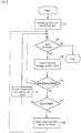
Fig. 2] Fig. 2 is a diagram illustrating the flow of the SpO2 feedback function. - [
Fig. 3A] Fig. 3A is a diagram illustrating the waveform of SpO2. - [
Fig. 3B] Fig. 3B is a diagram illustrating the waveform of SpO2. - [
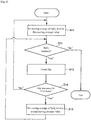
Fig. 4] Fig. 4 is a diagram illustrating the flow of switching between the first moving average and the second moving average. - [
Fig. 5A] Fig. 5A is a diagram illustrating the effect by SpO2 feedback. - [
Fig. 5B] Fig. 5B is a diagram illustrating the effect by SpO2 feedback. - An oxygen supply device of the embodiment of the present invention is explained taking an example of an oxygen concentration device as below, however the oxygen supply device of the present invention is not limited to the oxygen concentration device. The oxygen supply device may be an oxygen supply device that supplies an oxygen gas for inhalation using a high pressure oxygen gas filled in a cylinder
- An oxygen supply device of the embodiment has an SpO2 feedback function for controlling a flow rate of oxygen gas supply for inhalation based on percutaneous arterial oxygen saturation (SpO2) of the user. In the case where the oxygen concentration device has a fixed flow rate for the oxygen gas supply, the users are required to operate the oxygen concentration device by themselves and change the flow rate of the oxygen gas, otherwise there may happen deficiency or excess of the oxygen gas. For example, when the user of the oxygen concentration device shifts from a rest state to an elaboration state such as standing up and then starting walking, oxygen consumption in the body increases and accordingly the SpO2 decreases as shown in
Fig. 5A . Thus, unless the oxygen gas flow rate is changed from the rate prescribed for rest time to that for elaboration time, the user feels discomfort such as suffocation and the like. - On the other hand, when the SpO2 feedback function of the oxygen concentration device is activated, the oxygen gas flow rate is controlled based on the SpO2 measured with a pulse oximeter. The control unit of the oxygen concentration device detects an increase in oxygen consumption, caused by the user's shift from a rest state to an elaboration state, by a decrease in the SpO2, and then increases the oxygen gas flow rate to increase the SpO2. The increase in the oxygen gas flow rate keeps the SpO2 stable as shown in
Fig. 5B , thus the user can be prevented from feeling discomfort such as suffocation and the like. - The configuration of the oxygen concentration device of the embodiment of the present invention is represented in
Fig. 1 . The oxygen concentration device is a device that is used mainly in the home oxygen therapy as mentioned above and isolates nitrogen contained in the air and supplies high concentration oxygen (oxygen-enriched gas) as an oxygen gas for inhalation. The solid line and the dotted line connecting each component shown inFig. 1 represent main gas flow path and main path of electric signal such as control signal, respectively. - The oxygen concentration device is equipped with
main body 1,pulse oximeter 2 which is a sensor unit measuring SpO2 of a user of the oxygen concentration device, and cannula 3 suppling the oxygen gas to the user. - In the oxygen concentration device,
main body 1 containscompressor 102 supplying compressed air,adsorption cylinders 107 filled with an adsorbent selectively adsorbing nitrogen rather than oxygen, switchingvalve 105 switching the sequence such as adsorption step, desorption step and the like,control valve 104 increasing or decreasing a flow rate of the concentrated oxygen gas, and the like andcontrol unit 103 controlling these components.Control unit 103 is composed of, for example, CPU (central processing unit). - The oxygen gas is concentrated by
main body 1, the flow rate of which is adjusted bycontrol valve 104, and is supplied to a home oxygen therapy user via cannula 3.Control unit 1 03 controls controlvalve 104 so that the flow rate of the oxygen gas can be adjusted to a set point, for example, between 0.25 L/min and 5.00 L/min by an increment of 0.25 L/min.Pulse oximeter 2 as a sensor unit is attached to the fingertip and the like of the user, and measures SpO2 at a predetermined cycle (e.g., 30 Hz) and sends it to controlunit 103. - The raw material air is taken into
main body 1 through the air inlet provided withair inlet filter 101, which removes foreign substances such as dusts. At this time, about 21% of oxygen gas, about 77% of nitrogen gas, 0.8% of argon gas, and 1.2% of carbon dioxide and other gases are contained in the air. The oxygen concentration device concentrates the oxygen gas necessary for respiration gas and takes it out. - The raw material air taken into
main body 1 is compressed bycompressor 102, transferred toadsorption cylinders 107 filled with an adsorbent made of zeolite and the like which selectively adsorbs nitrogen molecules.Control unit 103, by operating switchingvalve 105, in turn, switches thetarget adsorption cylinders 107 and then supplies the compressed raw material air to the cylinder, and selectively adsorbs and removes the nitrogen gas that occupies about 77% of the raw material air in theadsorption cylinders 107. -
Adsorption cylinders 107 can adopt a well-known configuration such as multiple-cylinder type of three or more cylinders as well as single-cylinder and double-cylinder types, and for the purpose of continuous and efficient manufacture of oxygen-enriched gas from the raw material air,adsorption cylinders 107 preferably adopt a double-cylinder type or a multiple-cylinder type. In the case of a pressure swing adsorption type (PSA type) oxygen concentration device of a double-cylinder type, while one adsorption cylinder (cylinder A) executes an adsorption step, the other cylinder (cylinder B) executes a desorption step, and switchingvalve 105 is controlled so that steps of both cylinders are switched in turn between adsorption step and desorption step each in an opposite phase, and thus oxygen-enriched gas is manufactured continuously. - As
compressor 102, adopted is a compressor having only compression function or compression and vacuum functions such as a two-head swing-type air compressor, and in some cases, rotation-type air compressors including screw type, rotary type, scroll type and the like. A power supply for amotor driving compressor 102 may be AC or DC. - The nitrogen gas in the air is adsorbed on the adsorbent in
adsorption cylinder 107 at pressurized state, and the oxygen-enriched gas mainly composed of the unadsorbed oxygen is taken out ofadsorption cylinder 107. The oxygen-enriched gas taken out flows intoproduct tank 106 throughcheck valve 108 provided to prevent backflow intoadsorption cylinder 107 and is accumulated inproduct tank 106. The oxygen-enriched gas accumulated inproduct tank 106 is an oxygen gas with high concentration of, for example, 95%. -
Control unit 103 controls controlvalve 104 to adjust the oxygen gas to a flow rate prescribed by a physician and the like and supplies the oxygen gas to a patient through cannula 3. Oxygen concentration/flow rate sensor 110 feeds back values of flow rate and oxygen concentration of the supplied oxygen gas to controlunit 103, and manufacture and supply of the oxygen gas by the oxygen concentration device are controlled. - An example of SpO2 feedback control executed by
control unit 103 is shown inFig. 2 . When the oxygen concentration device is set to SpO2 feedback mode,control unit 103 controls controlvalve 104 so that the oxygen gas supplied to the user through cannula 3 is adjusted to a predetermined initial flow rate (step S1). Then,control unit 103 confirms that SpO2 feedback mode is activated (step S2), and starts the acquisition of SpO2 information usingpulse oximeter 2 at a predetermined cycle. - Once the acquisition of SpO2 information is started,
control unit 103 calculates a moving average value of SpO2 at each cycle and stores it in a storage unit such as memory. At least two types of moving average value are calculated for SpO2: the first moving average value of SpO2 calculated over a short span (e.g., one second or longer and five seconds or shorter), and the second moving average value of SpO2 over a longer span than the time span for the first moving average value (e.g., two minutes or longer and five minutes or shorter). - In step S3,
control unit 103 acquires, at a predetermined time interval, the latest value from time series of the moving average value of SpO2 in a storage unit such as memory. The moving average value of SpO2 acquired in step S3 is either the first moving average value or the second moving average value. It is explained below which of the first moving average value and the second moving average value is acquired. -
Control unit 103 checks whether the acquired moving average value of SpO2 is in the prescribed range of SpO2 (e.g., 90% or more, 94% or less) (step S4). If the moving average value of SpO2 is within the prescribed range of SpO2,control unit 103 goes back to step S2, and repeats feedback control until SpO2 feedback mode is off. - When judging that the moving average value of SpO2 is out of the prescribed range of SpO2 (e.g., less than 90% or more than 94%.) in step S4,
control unit 103 raises the flow rate of the oxygen gas by one level in the case of the moving average value of SpO2 < 90% (step S5, step S6) and increases the oxygen gas supply to the user to increase SpO2.Control unit 103 lowers the flow rate of the oxygen gas by one level in the case of the moving average value of SpO2 > 94% (step S5, step S7). -
Control unit 103 controls controlvalve 104 to increase/decrease the flow rate of the oxygen gas. For example, in the oxygen concentration device of the embodiment, the flow rate of the oxygen gas can be adjusted by a division of 0.25 L/min, and thus the raising/lowering the oxygen gas flow rate by one level corresponds to an increase/decrease of the flow rate by 0.25 L/min.Control unit 103 increases/decreases the flow rate of the oxygen gas when the moving average value of SpO2 is below/over the prescribed range of SpO2, and returns SpO2 within the range of SpO2 prescribed by a healthcare worker, thus preventing the user from feeling discomfort even during sleep, which is expected to enhance the effect of the home oxygen therapy. The method for adjusting flow rate is not limited to the above-mentioned method, and a method such as, for example, PID control may be adopted. - In the oxygen concentration device of the embodiment, the moving average value of SpO2 used for the control is switched, after judging the presence of SAS symptom, between the first moving average value and the second moving average value calculated over longer time span than the first moving average. As mentioned above, it is known that an apnea symptom of an SAS patient during sleep causes an appearance of a sudden downward peak (Dip) of SpO2 below baseline (PTL 3). The oxygen concentration device measures SpO2 of the user during sleep using
pulse oximeter 2, andcontrol unit 103 detects an appearance of Dip. - An example of waveform of SpO2 during sleep measured from an SAS patient is shown in
Fig. 3A. Fig. 3A shows frequent appearances of Dip, a sudden downward peak of SpO2, during about 22:00-2:00.Control unit 103 of the oxygen concentration device, when recognizing the appearance of a peak as represented inFig. 3B , having a decrease of 3% or more from the base line within 90 seconds and a recovery within 30 seconds, judges and counts this peak as Dip. At this time, the baseline is prepared using moving average of SpO2 calculated over, for example, 3minutes. - Then, when a Dip frequency during predetermined time is equal to or more than the first threshold set in advance,
control unit 103 judges that with high possibility, the user is an SAS patient and shows an apnea symptom. Generally, oxygen desaturation index (ODI: Dip appearance frequency per hour) of less than 15 is judged as no occurrence of an SAS symptom, and ODI of 15 or more can be judged as highly possible occurrence of an SAS symptom, and thus the first threshold may be set to, for example, 15 Dips per hour. -
Control unit 103 starts measurement of SpO2 usingpulse oximeter 2 at a predetermined cycle, and, at the same time, starts calculation of a moving average value of Sp02: the first moving average value and the second moving average value over a time span longer than the span for the first moving average value. The first moving average value is a moving average value calculated from SpO2 over the latest, for example, 2 seconds, and the second moving average value is a moving average value calculated from SpO2 over the latest, for example, 2 minutes. -
Control unit 103 acquires the first moving average value as the moving average value of SpO2 of step S3 inFig. 2 as an initial setting and executes SpO2 feedback control. The first moving average value is calculated from SpO2 over a time span of 2 seconds, and enables fine control of the gas flow rate. Thus, when SpO2 slightly deviates from the prescribed range of SpO2,control unit 103 immediately increases/decreases the oxygen gas flow rate, and can return the SpO2 within the prescribed level. As long as the Dip frequency during predetermined time is less than the first threshold,control unit 103 executes SpO2 feedback control using the first moving average value. - When the Dip frequency during predetermined time is equal to or more than the first threshold,
control unit 103 judges that with high possibility, the user is an SAS patient and shows an apnea symptom, and switches the moving average value of SpO2 acquired in step S3 from the first moving average to the second moving average. The switch to the second moving average value calculated over the latest 2 minutes can reduce the influence from the Dip appearing in the SpO2 waveform of SAS patients. The SpO2 feedback control ofFig. 2 using the second moving average value can prevent the oxygen gas flow rate from greatly increasing/decreasing in a short time due to frequent occurrence of Dip in a short time. Thus, it can prevent a user in sleep from feeling discomfort due to a sudden change in the oxygen gas flow rate. - After the moving average value of SpO2 is switched from the first moving average value to the second moving average value, when detecting that the Dip frequency during a predetermined time is less than a second threshold,
control unit 103 may switch the moving average value of SpO2 acquired in step S3 ofFig. 2 back to the first moving average value from the second moving average value. The second threshold may be the same as the first threshold, or may be smaller than the first threshold considering safety. - An example of the control flow to switch between the first moving average value and the second moving average value depending on the Dip frequency during a predetermined time is shown in
Fig. 4 . When the oxygen concentration device is set to an SpO2 feedback mode,control unit 103 counts the occurrence of Dip according to the flow ofFig. 4 while controlling the oxygen gas flow rate according to the flow ofFig. 2 . At first,control unit 103 gives an instruction to assign the first moving average value to the moving average value of SpO2 acquired in step 3 (step S11). Then,control unit 103 confirms that the SpO2 feedback mode is activated (step S12), and then counts the Dip frequency (step S13). -
Control unit 103 judges whether the counted Dip frequency per hour is equal to or more than the first threshold of 15 (step S14), and when the frequency is less than 15, returns to step S11. When the frequency is 15 or more,control unit 103 gives an instruction to assign the second moving average value to the moving average value of SpO2 to be acquired in step 3. As long as the Dip frequency per hour is equal to or more than the first threshold of 15, the moving average value of SpO2 used in control flow ofFig. 2 is the second moving average value, and the Dip occurrence can be prevented from causing a large increase/decrease of the oxygen gas flow rate in a short time. - Though the preferred embodiment of the present invention was explained in detail as above, the present invention is not limited to the embodiment mentioned above, and various kinds of variation and modification are possible within the contents of the present invention described in the scope of claims.
- In accordance with the present invention, an oxygen gas supply device and a control method thereof can be provided that feedbacks SpO2 while switching among moving average values of SpO2 over different time spans and can control the oxygen gas flow rate suitably even for an SAS patient.
-
- 1. Main body
- 2. Pulse oximeter
- 3. Cannula
- 101. Air inlet filter
- 102. Compressor
- 103. Control unit
- 104. Control valve
- 105. Switching valve
- 106. Product tank
- 107. Adsorption cylinder
- 108. Check valve
- 109. Pressure regulating valve
- 110. Oxygen concentration/flow rate sensor
Claims (7)
- An oxygen supply device having a function for controlling a flow rate of an oxygen gas supplied to a user for inhalation based on percutaneous arterial oxygen saturation (SpO2) comprising:a sensor unit acquiring information on percutaneous arterial oxygen saturation (SpO2) of the user, anda control unit controlling a supply rate of the oxygen gas based on the information on percutaneous arterial oxygen saturation (SpO2) acquired from the sensor unit and calculating a moving average value of SpO2 and a Dip frequency per predetermined time from the information on percutaneous arterial oxygen saturation (SpO2),wherein the control unit calculates a first moving average value of SpO2 calculated over a first time span, a second moving average value of SpO2 calculated over a second time span which is longer than the first time span, and a Dip frequency per predetermined time from the information on percutaneous arterial oxygen saturation (SpO2) acquired by the sensor unit, selects either of the first moving average value or the second moving average value based on the calculated Dip frequency, and controls the supply rate of the oxygen gas based on the selected moving average value.
- The oxygen supply device according to claim 1, wherein the control unit controls the flow rate of the oxygen gas based on the first moving average value when the Dip frequency is less than a first threshold, and based on the second moving average value when the Dip frequency is equal to or more than the first threshold.
- The oxygen supply device according to claim 1 or 2, wherein the oxygen supply device is an oxygen concentration device that supplies an oxygen-enriched gas obtained by concentrating oxygen in the air as the oxygen gas.
- The oxygen supply device according to claim 1 or 2, wherein the oxygen supply device supplies a high-pressure oxygen gas filled in a cylinder as the oxygen gas.
- The oxygen supply device according to any one of claims 1 to 4, wherein the first time span is one second or longer and five seconds or shorter, and the second time span is two minutes or longer and five minutes or shorter.
- A control method for an oxygen supply device for controlling a flow rate of an oxygen gas supplied to a user for inhalation based on percutaneous arterial oxygen saturation (SpO2) comprising:a first step of acquiring information on percutaneous arterial oxygen saturation (SpO2) of the user,a second step of calculating a first moving average value of SpO2 calculated over a first time span and a second moving average value of SpO2 calculated over a second time span which is longer than the first time span from the information on percutaneous arterial oxygen saturation (SpO2), and a third step of calculating a Dip frequency per predetermined time from the information on percutaneous arterial oxygen saturation (SpO2).
- The control method for an oxygen supply device according to claim 6, further comprising a fourth step of controlling the flow rate of the oxygen gas based on the first moving average value when the Dip frequency is less than a first threshold, and based on the second moving average value when the Dip frequency is equal to or more than the first threshold.
Applications Claiming Priority (2)
| Application Number | Priority Date | Filing Date | Title |
|---|---|---|---|
| JP2017071963 | 2017-03-31 | ||
| PCT/JP2018/010819 WO2018180707A1 (en) | 2017-03-31 | 2018-03-19 | Oxygen supply device and method for controlling same |
Publications (3)
| Publication Number | Publication Date |
|---|---|
| EP3603713A1 true EP3603713A1 (en) | 2020-02-05 |
| EP3603713A4 EP3603713A4 (en) | 2020-04-01 |
| EP3603713B1 EP3603713B1 (en) | 2021-08-11 |
Family
ID=63675749
Family Applications (1)
| Application Number | Title | Priority Date | Filing Date |
|---|---|---|---|
| EP18777562.2A Active EP3603713B1 (en) | 2017-03-31 | 2018-03-19 | Oxygen supply device |
Country Status (7)
| Country | Link |
|---|---|
| US (1) | US11338101B2 (en) |
| EP (1) | EP3603713B1 (en) |
| JP (1) | JP6821012B2 (en) |
| KR (1) | KR102519783B1 (en) |
| CN (1) | CN110446519B (en) |
| ES (1) | ES2886200T3 (en) |
| WO (1) | WO2018180707A1 (en) |
Families Citing this family (5)
| Publication number | Priority date | Publication date | Assignee | Title |
|---|---|---|---|---|
| CN111544834B (en) * | 2020-05-12 | 2021-06-25 | 苏州市中西医结合医院 | Cardiopulmonary rehabilitation training method |
| CN112169100A (en) * | 2020-09-27 | 2021-01-05 | 湖南明康中锦医疗科技发展有限公司 | Method for automatically adjusting oxygen concentration of gas transmission by high-flow equipment |
| CN113289182B (en) * | 2021-07-09 | 2023-09-15 | 重庆医科大学附属第一医院 | Oxygen therapy monitoring regulation and control system and regulation and control method |
| CN114225251B (en) * | 2021-12-17 | 2022-08-09 | 中国科学院合肥物质科学研究院 | Oxygen suppliment control system based on IMU |
| CN117398557B (en) * | 2023-10-16 | 2026-04-17 | 首都医科大学宣武医院 | A smart emergency respiratory support system and its driving method |
Family Cites Families (12)
| Publication number | Priority date | Publication date | Assignee | Title |
|---|---|---|---|---|
| JP3374424B2 (en) | 1992-12-28 | 2003-02-04 | 山陽電子工業株式会社 | Medical oxygen supply device |
| JP4205470B2 (en) | 2003-04-02 | 2009-01-07 | 帝人株式会社 | Inspection device, treatment system |
| JP2006204742A (en) | 2005-01-31 | 2006-08-10 | Konica Minolta Sensing Inc | Method and system for evaluating sleep, its operation program, pulse oxymeter, and system for supporting sleep |
| US7810497B2 (en) * | 2006-03-20 | 2010-10-12 | Ric Investments, Llc | Ventilatory control system |
| JP4613280B2 (en) | 2006-04-07 | 2011-01-12 | コニカミノルタセンシング株式会社 | Sleep apnea syndrome screening system and its operation program |
| JP5261731B2 (en) | 2006-09-14 | 2013-08-14 | イマジニアリング株式会社 | Oxygen supply equipment |
| US20130172759A1 (en) * | 2011-08-08 | 2013-07-04 | Richard J. Melker | Systems And Methods For Using Photoplethysmography In The Administration Of Narcotic Reversal Agents |
| JP5986413B2 (en) | 2012-03-30 | 2016-09-06 | フクダ電子株式会社 | Biological information display device, oxygen supply device, therapeutic device, and biological information measuring device |
| JP6211753B2 (en) | 2012-09-26 | 2017-10-11 | 帝人ファーマ株式会社 | Cylindrical unit fixing method and oxygen concentrator using the same method |
| US11291868B2 (en) * | 2013-12-20 | 2022-04-05 | B/E Aerospace, Inc. | Pulse saturation oxygen delivery system and method |
| US10869987B2 (en) * | 2013-12-20 | 2020-12-22 | B/E Aerospace, Inc | Pulse saturation oxygen delivery system and method |
| NZ630749A (en) * | 2014-02-13 | 2016-03-31 | Resmed Ltd | Real-time detection of periodic breathing |
-
2018
- 2018-03-19 JP JP2019509350A patent/JP6821012B2/en active Active
- 2018-03-19 ES ES18777562T patent/ES2886200T3/en active Active
- 2018-03-19 EP EP18777562.2A patent/EP3603713B1/en active Active
- 2018-03-19 KR KR1020197031184A patent/KR102519783B1/en active Active
- 2018-03-19 CN CN201880022416.XA patent/CN110446519B/en active Active
- 2018-03-19 WO PCT/JP2018/010819 patent/WO2018180707A1/en not_active Ceased
- 2018-03-19 US US16/497,646 patent/US11338101B2/en active Active
Also Published As
| Publication number | Publication date |
|---|---|
| EP3603713B1 (en) | 2021-08-11 |
| KR102519783B1 (en) | 2023-04-07 |
| US20210283355A1 (en) | 2021-09-16 |
| US11338101B2 (en) | 2022-05-24 |
| KR20190130150A (en) | 2019-11-21 |
| EP3603713A4 (en) | 2020-04-01 |
| CN110446519A (en) | 2019-11-12 |
| ES2886200T3 (en) | 2021-12-16 |
| JP6821012B2 (en) | 2021-01-27 |
| WO2018180707A1 (en) | 2018-10-04 |
| CN110446519B (en) | 2021-12-17 |
| JPWO2018180707A1 (en) | 2019-11-07 |
Similar Documents
| Publication | Publication Date | Title |
|---|---|---|
| EP3603713B1 (en) | Oxygen supply device | |
| US12109359B2 (en) | Oxygen supply device and method for controlling same | |
| AU2007227105B2 (en) | Ventilatory control system | |
| KR102540426B1 (en) | oxygen therapy system | |
| EP2121092B1 (en) | Apparatus for delivering a dose of a gaseous drug to a patient | |
| EP3365052B1 (en) | Connection of a spontaneous delivery device to a concentrator | |
| Linton et al. | Automatic weaning from mechanical ventilation using an adaptive lung ventilation controller | |
| US20090050152A1 (en) | Device and Method for Automatically Regulating Supplemental Oxygen Flow-Rate | |
| AU2008261876A1 (en) | System and method for treating ventilatory instability | |
| JP2019162337A (en) | Oxygen concentrator and its control method | |
| JP6109507B2 (en) | Oxygen supply equipment | |
| WO2020181279A1 (en) | Respiratory support device and method of providing hypoxemia relief | |
| US20210170136A1 (en) | Process for supporting blood gas exchange by ventilation and extracorporeal blood gas exchange and system operating according to the process | |
| JP5139657B2 (en) | Pressure fluctuation adsorption type oxygen concentrator |
Legal Events
| Date | Code | Title | Description |
|---|---|---|---|
| STAA | Information on the status of an ep patent application or granted ep patent |
Free format text: STATUS: THE INTERNATIONAL PUBLICATION HAS BEEN MADE |
|
| PUAI | Public reference made under article 153(3) epc to a published international application that has entered the european phase |
Free format text: ORIGINAL CODE: 0009012 |
|
| STAA | Information on the status of an ep patent application or granted ep patent |
Free format text: STATUS: REQUEST FOR EXAMINATION WAS MADE |
|
| 17P | Request for examination filed |
Effective date: 20190927 |
|
| AK | Designated contracting states |
Kind code of ref document: A1 Designated state(s): AL AT BE BG CH CY CZ DE DK EE ES FI FR GB GR HR HU IE IS IT LI LT LU LV MC MK MT NL NO PL PT RO RS SE SI SK SM TR |
|
| AX | Request for extension of the european patent |
Extension state: BA ME |
|
| A4 | Supplementary search report drawn up and despatched |
Effective date: 20200304 |
|
| RIC1 | Information provided on ipc code assigned before grant |
Ipc: A61M 16/00 20060101AFI20200227BHEP Ipc: A61M 16/10 20060101ALI20200227BHEP |
|
| DAV | Request for validation of the european patent (deleted) | ||
| DAX | Request for extension of the european patent (deleted) | ||
| STAA | Information on the status of an ep patent application or granted ep patent |
Free format text: STATUS: EXAMINATION IS IN PROGRESS |
|
| 17Q | First examination report despatched |
Effective date: 20210305 |
|
| GRAP | Despatch of communication of intention to grant a patent |
Free format text: ORIGINAL CODE: EPIDOSNIGR1 |
|
| STAA | Information on the status of an ep patent application or granted ep patent |
Free format text: STATUS: GRANT OF PATENT IS INTENDED |
|
| INTG | Intention to grant announced |
Effective date: 20210519 |
|
| GRAS | Grant fee paid |
Free format text: ORIGINAL CODE: EPIDOSNIGR3 |
|
| GRAA | (expected) grant |
Free format text: ORIGINAL CODE: 0009210 |
|
| STAA | Information on the status of an ep patent application or granted ep patent |
Free format text: STATUS: THE PATENT HAS BEEN GRANTED |
|
| AK | Designated contracting states |
Kind code of ref document: B1 Designated state(s): AL AT BE BG CH CY CZ DE DK EE ES FI FR GB GR HR HU IE IS IT LI LT LU LV MC MK MT NL NO PL PT RO RS SE SI SK SM TR |
|
| REG | Reference to a national code |
Ref country code: CH Ref legal event code: EP |
|
| REG | Reference to a national code |
Ref country code: DE Ref legal event code: R096 Ref document number: 602018021761 Country of ref document: DE |
|
| REG | Reference to a national code |
Ref country code: IE Ref legal event code: FG4D Ref country code: AT Ref legal event code: REF Ref document number: 1418735 Country of ref document: AT Kind code of ref document: T Effective date: 20210915 |
|
| REG | Reference to a national code |
Ref country code: LT Ref legal event code: MG9D |
|
| REG | Reference to a national code |
Ref country code: NL Ref legal event code: MP Effective date: 20210811 |
|
| REG | Reference to a national code |
Ref country code: ES Ref legal event code: FG2A Ref document number: 2886200 Country of ref document: ES Kind code of ref document: T3 Effective date: 20211216 |
|
| REG | Reference to a national code |
Ref country code: AT Ref legal event code: MK05 Ref document number: 1418735 Country of ref document: AT Kind code of ref document: T Effective date: 20210811 |
|
| PG25 | Lapsed in a contracting state [announced via postgrant information from national office to epo] |
Ref country code: LT Free format text: LAPSE BECAUSE OF FAILURE TO SUBMIT A TRANSLATION OF THE DESCRIPTION OR TO PAY THE FEE WITHIN THE PRESCRIBED TIME-LIMIT Effective date: 20210811 Ref country code: AT Free format text: LAPSE BECAUSE OF FAILURE TO SUBMIT A TRANSLATION OF THE DESCRIPTION OR TO PAY THE FEE WITHIN THE PRESCRIBED TIME-LIMIT Effective date: 20210811 Ref country code: BG Free format text: LAPSE BECAUSE OF FAILURE TO SUBMIT A TRANSLATION OF THE DESCRIPTION OR TO PAY THE FEE WITHIN THE PRESCRIBED TIME-LIMIT Effective date: 20211111 Ref country code: PT Free format text: LAPSE BECAUSE OF FAILURE TO SUBMIT A TRANSLATION OF THE DESCRIPTION OR TO PAY THE FEE WITHIN THE PRESCRIBED TIME-LIMIT Effective date: 20211213 Ref country code: NO Free format text: LAPSE BECAUSE OF FAILURE TO SUBMIT A TRANSLATION OF THE DESCRIPTION OR TO PAY THE FEE WITHIN THE PRESCRIBED TIME-LIMIT Effective date: 20211111 Ref country code: HR Free format text: LAPSE BECAUSE OF FAILURE TO SUBMIT A TRANSLATION OF THE DESCRIPTION OR TO PAY THE FEE WITHIN THE PRESCRIBED TIME-LIMIT Effective date: 20210811 Ref country code: FI Free format text: LAPSE BECAUSE OF FAILURE TO SUBMIT A TRANSLATION OF THE DESCRIPTION OR TO PAY THE FEE WITHIN THE PRESCRIBED TIME-LIMIT Effective date: 20210811 Ref country code: RS Free format text: LAPSE BECAUSE OF FAILURE TO SUBMIT A TRANSLATION OF THE DESCRIPTION OR TO PAY THE FEE WITHIN THE PRESCRIBED TIME-LIMIT Effective date: 20210811 Ref country code: SE Free format text: LAPSE BECAUSE OF FAILURE TO SUBMIT A TRANSLATION OF THE DESCRIPTION OR TO PAY THE FEE WITHIN THE PRESCRIBED TIME-LIMIT Effective date: 20210811 |
|
| PG25 | Lapsed in a contracting state [announced via postgrant information from national office to epo] |
Ref country code: PL Free format text: LAPSE BECAUSE OF FAILURE TO SUBMIT A TRANSLATION OF THE DESCRIPTION OR TO PAY THE FEE WITHIN THE PRESCRIBED TIME-LIMIT Effective date: 20210811 Ref country code: LV Free format text: LAPSE BECAUSE OF FAILURE TO SUBMIT A TRANSLATION OF THE DESCRIPTION OR TO PAY THE FEE WITHIN THE PRESCRIBED TIME-LIMIT Effective date: 20210811 Ref country code: GR Free format text: LAPSE BECAUSE OF FAILURE TO SUBMIT A TRANSLATION OF THE DESCRIPTION OR TO PAY THE FEE WITHIN THE PRESCRIBED TIME-LIMIT Effective date: 20211112 |
|
| PG25 | Lapsed in a contracting state [announced via postgrant information from national office to epo] |
Ref country code: NL Free format text: LAPSE BECAUSE OF FAILURE TO SUBMIT A TRANSLATION OF THE DESCRIPTION OR TO PAY THE FEE WITHIN THE PRESCRIBED TIME-LIMIT Effective date: 20210811 |
|
| PG25 | Lapsed in a contracting state [announced via postgrant information from national office to epo] |
Ref country code: DK Free format text: LAPSE BECAUSE OF FAILURE TO SUBMIT A TRANSLATION OF THE DESCRIPTION OR TO PAY THE FEE WITHIN THE PRESCRIBED TIME-LIMIT Effective date: 20210811 |
|
| REG | Reference to a national code |
Ref country code: DE Ref legal event code: R097 Ref document number: 602018021761 Country of ref document: DE |
|
| PG25 | Lapsed in a contracting state [announced via postgrant information from national office to epo] |
Ref country code: SM Free format text: LAPSE BECAUSE OF FAILURE TO SUBMIT A TRANSLATION OF THE DESCRIPTION OR TO PAY THE FEE WITHIN THE PRESCRIBED TIME-LIMIT Effective date: 20210811 Ref country code: SK Free format text: LAPSE BECAUSE OF FAILURE TO SUBMIT A TRANSLATION OF THE DESCRIPTION OR TO PAY THE FEE WITHIN THE PRESCRIBED TIME-LIMIT Effective date: 20210811 Ref country code: RO Free format text: LAPSE BECAUSE OF FAILURE TO SUBMIT A TRANSLATION OF THE DESCRIPTION OR TO PAY THE FEE WITHIN THE PRESCRIBED TIME-LIMIT Effective date: 20210811 Ref country code: EE Free format text: LAPSE BECAUSE OF FAILURE TO SUBMIT A TRANSLATION OF THE DESCRIPTION OR TO PAY THE FEE WITHIN THE PRESCRIBED TIME-LIMIT Effective date: 20210811 Ref country code: CZ Free format text: LAPSE BECAUSE OF FAILURE TO SUBMIT A TRANSLATION OF THE DESCRIPTION OR TO PAY THE FEE WITHIN THE PRESCRIBED TIME-LIMIT Effective date: 20210811 Ref country code: AL Free format text: LAPSE BECAUSE OF FAILURE TO SUBMIT A TRANSLATION OF THE DESCRIPTION OR TO PAY THE FEE WITHIN THE PRESCRIBED TIME-LIMIT Effective date: 20210811 |
|
| PLBE | No opposition filed within time limit |
Free format text: ORIGINAL CODE: 0009261 |
|
| STAA | Information on the status of an ep patent application or granted ep patent |
Free format text: STATUS: NO OPPOSITION FILED WITHIN TIME LIMIT |
|
| 26N | No opposition filed |
Effective date: 20220512 |
|
| PG25 | Lapsed in a contracting state [announced via postgrant information from national office to epo] |
Ref country code: SI Free format text: LAPSE BECAUSE OF FAILURE TO SUBMIT A TRANSLATION OF THE DESCRIPTION OR TO PAY THE FEE WITHIN THE PRESCRIBED TIME-LIMIT Effective date: 20210811 |
|
| PG25 | Lapsed in a contracting state [announced via postgrant information from national office to epo] |
Ref country code: MC Free format text: LAPSE BECAUSE OF FAILURE TO SUBMIT A TRANSLATION OF THE DESCRIPTION OR TO PAY THE FEE WITHIN THE PRESCRIBED TIME-LIMIT Effective date: 20210811 |
|
| REG | Reference to a national code |
Ref country code: CH Ref legal event code: PL |
|
| GBPC | Gb: european patent ceased through non-payment of renewal fee |
Effective date: 20220319 |
|
| REG | Reference to a national code |
Ref country code: BE Ref legal event code: MM Effective date: 20220331 |
|
| PG25 | Lapsed in a contracting state [announced via postgrant information from national office to epo] |
Ref country code: LU Free format text: LAPSE BECAUSE OF NON-PAYMENT OF DUE FEES Effective date: 20220319 Ref country code: LI Free format text: LAPSE BECAUSE OF NON-PAYMENT OF DUE FEES Effective date: 20220331 Ref country code: IE Free format text: LAPSE BECAUSE OF NON-PAYMENT OF DUE FEES Effective date: 20220319 Ref country code: GB Free format text: LAPSE BECAUSE OF NON-PAYMENT OF DUE FEES Effective date: 20220319 Ref country code: CH Free format text: LAPSE BECAUSE OF NON-PAYMENT OF DUE FEES Effective date: 20220331 |
|
| PG25 | Lapsed in a contracting state [announced via postgrant information from national office to epo] |
Ref country code: BE Free format text: LAPSE BECAUSE OF NON-PAYMENT OF DUE FEES Effective date: 20220331 |
|
| REG | Reference to a national code |
Ref country code: DE Ref legal event code: R081 Ref document number: 602018021761 Country of ref document: DE Owner name: TEIJIN LIMITED, OSAKA-SHI, JP Free format text: FORMER OWNER: TEIJIN PHARMA LIMITED, TOKYO, JP |
|
| REG | Reference to a national code |
Ref country code: ES Ref legal event code: PC2A Owner name: TEIJIN LIMITED Effective date: 20230612 |
|
| PG25 | Lapsed in a contracting state [announced via postgrant information from national office to epo] |
Ref country code: MK Free format text: LAPSE BECAUSE OF FAILURE TO SUBMIT A TRANSLATION OF THE DESCRIPTION OR TO PAY THE FEE WITHIN THE PRESCRIBED TIME-LIMIT Effective date: 20210811 Ref country code: CY Free format text: LAPSE BECAUSE OF FAILURE TO SUBMIT A TRANSLATION OF THE DESCRIPTION OR TO PAY THE FEE WITHIN THE PRESCRIBED TIME-LIMIT Effective date: 20210811 |
|
| PG25 | Lapsed in a contracting state [announced via postgrant information from national office to epo] |
Ref country code: HU Free format text: LAPSE BECAUSE OF FAILURE TO SUBMIT A TRANSLATION OF THE DESCRIPTION OR TO PAY THE FEE WITHIN THE PRESCRIBED TIME-LIMIT; INVALID AB INITIO Effective date: 20180319 |
|
| PG25 | Lapsed in a contracting state [announced via postgrant information from national office to epo] |
Ref country code: MT Free format text: LAPSE BECAUSE OF FAILURE TO SUBMIT A TRANSLATION OF THE DESCRIPTION OR TO PAY THE FEE WITHIN THE PRESCRIBED TIME-LIMIT Effective date: 20210811 |
|
| PGFP | Annual fee paid to national office [announced via postgrant information from national office to epo] |
Ref country code: ES Payment date: 20250429 Year of fee payment: 8 |
|
| PG25 | Lapsed in a contracting state [announced via postgrant information from national office to epo] |
Ref country code: TR Free format text: LAPSE BECAUSE OF FAILURE TO SUBMIT A TRANSLATION OF THE DESCRIPTION OR TO PAY THE FEE WITHIN THE PRESCRIBED TIME-LIMIT Effective date: 20210811 |
|
| PGFP | Annual fee paid to national office [announced via postgrant information from national office to epo] |
Ref country code: DE Payment date: 20260319 Year of fee payment: 9 |
|
| PGFP | Annual fee paid to national office [announced via postgrant information from national office to epo] |
Ref country code: IT Payment date: 20260324 Year of fee payment: 9 |
|
| PGFP | Annual fee paid to national office [announced via postgrant information from national office to epo] |
Ref country code: FR Payment date: 20260320 Year of fee payment: 9 |