EP3603550A1 - Dilator - Google Patents
Dilator Download PDFInfo
- Publication number
- EP3603550A1 EP3603550A1 EP18772158.4A EP18772158A EP3603550A1 EP 3603550 A1 EP3603550 A1 EP 3603550A1 EP 18772158 A EP18772158 A EP 18772158A EP 3603550 A1 EP3603550 A1 EP 3603550A1
- Authority
- EP
- European Patent Office
- Prior art keywords
- shaft
- spirally
- dilator
- coil
- protruding portion
- Prior art date
- Legal status (The legal status is an assumption and is not a legal conclusion. Google has not performed a legal analysis and makes no representation as to the accuracy of the status listed.)
- Granted
Links
Images


Classifications
-
- A—HUMAN NECESSITIES
- A61—MEDICAL OR VETERINARY SCIENCE; HYGIENE
- A61B—DIAGNOSIS; SURGERY; IDENTIFICATION
- A61B17/00—Surgical instruments, devices or methods
- A61B17/34—Trocars; Puncturing needles
- A61B17/3417—Details of tips or shafts, e.g. grooves, expandable, bendable; Multiple coaxial sliding cannulas, e.g. for dilating
-
- A—HUMAN NECESSITIES
- A61—MEDICAL OR VETERINARY SCIENCE; HYGIENE
- A61M—DEVICES FOR INTRODUCING MEDIA INTO, OR ONTO, THE BODY; DEVICES FOR TRANSDUCING BODY MEDIA OR FOR TAKING MEDIA FROM THE BODY; DEVICES FOR PRODUCING OR ENDING SLEEP OR STUPOR
- A61M29/00—Dilators with or without means for introducing media, e.g. remedies
-
- A—HUMAN NECESSITIES
- A61—MEDICAL OR VETERINARY SCIENCE; HYGIENE
- A61B—DIAGNOSIS; SURGERY; IDENTIFICATION
- A61B90/00—Instruments, implements or accessories specially adapted for surgery or diagnosis and not covered by any of the groups A61B1/00 - A61B50/00, e.g. for luxation treatment or for protecting wound edges
- A61B90/02—Devices for expanding tissue, e.g. skin tissue
-
- A—HUMAN NECESSITIES
- A61—MEDICAL OR VETERINARY SCIENCE; HYGIENE
- A61M—DEVICES FOR INTRODUCING MEDIA INTO, OR ONTO, THE BODY; DEVICES FOR TRANSDUCING BODY MEDIA OR FOR TAKING MEDIA FROM THE BODY; DEVICES FOR PRODUCING OR ENDING SLEEP OR STUPOR
- A61M25/00—Catheters; Hollow probes
- A61M25/0021—Catheters; Hollow probes characterised by the form of the tubing
- A61M25/0023—Catheters; Hollow probes characterised by the form of the tubing by the form of the lumen, e.g. cross-section, variable diameter
-
- A—HUMAN NECESSITIES
- A61—MEDICAL OR VETERINARY SCIENCE; HYGIENE
- A61M—DEVICES FOR INTRODUCING MEDIA INTO, OR ONTO, THE BODY; DEVICES FOR TRANSDUCING BODY MEDIA OR FOR TAKING MEDIA FROM THE BODY; DEVICES FOR PRODUCING OR ENDING SLEEP OR STUPOR
- A61M25/00—Catheters; Hollow probes
- A61M25/0043—Catheters; Hollow probes characterised by structural features
- A61M25/005—Catheters; Hollow probes characterised by structural features with embedded materials for reinforcement, e.g. wires, coils, braids
- A61M25/0053—Catheters; Hollow probes characterised by structural features with embedded materials for reinforcement, e.g. wires, coils, braids having a variable stiffness along the longitudinal axis, e.g. by varying the pitch of the coil or braid
-
- A—HUMAN NECESSITIES
- A61—MEDICAL OR VETERINARY SCIENCE; HYGIENE
- A61B—DIAGNOSIS; SURGERY; IDENTIFICATION
- A61B17/00—Surgical instruments, devices or methods
- A61B2017/00831—Material properties
- A61B2017/00902—Material properties transparent or translucent
- A61B2017/00915—Material properties transparent or translucent for radioactive radiation
-
- A—HUMAN NECESSITIES
- A61—MEDICAL OR VETERINARY SCIENCE; HYGIENE
- A61B—DIAGNOSIS; SURGERY; IDENTIFICATION
- A61B17/00—Surgical instruments, devices or methods
- A61B17/34—Trocars; Puncturing needles
- A61B17/3417—Details of tips or shafts, e.g. grooves, expandable, bendable; Multiple coaxial sliding cannulas, e.g. for dilating
- A61B2017/3454—Details of tips
- A61B2017/3456—Details of tips blunt
-
- A—HUMAN NECESSITIES
- A61—MEDICAL OR VETERINARY SCIENCE; HYGIENE
- A61B—DIAGNOSIS; SURGERY; IDENTIFICATION
- A61B17/00—Surgical instruments, devices or methods
- A61B17/34—Trocars; Puncturing needles
- A61B17/3417—Details of tips or shafts, e.g. grooves, expandable, bendable; Multiple coaxial sliding cannulas, e.g. for dilating
- A61B2017/3454—Details of tips
- A61B2017/3458—Details of tips threaded
-
- A—HUMAN NECESSITIES
- A61—MEDICAL OR VETERINARY SCIENCE; HYGIENE
- A61B—DIAGNOSIS; SURGERY; IDENTIFICATION
- A61B90/00—Instruments, implements or accessories specially adapted for surgery or diagnosis and not covered by any of the groups A61B1/00 - A61B50/00, e.g. for luxation treatment or for protecting wound edges
- A61B90/39—Markers, e.g. radio-opaque or breast lesions markers
- A61B2090/3966—Radiopaque markers visible in an X-ray image
-
- A—HUMAN NECESSITIES
- A61—MEDICAL OR VETERINARY SCIENCE; HYGIENE
- A61M—DEVICES FOR INTRODUCING MEDIA INTO, OR ONTO, THE BODY; DEVICES FOR TRANSDUCING BODY MEDIA OR FOR TAKING MEDIA FROM THE BODY; DEVICES FOR PRODUCING OR ENDING SLEEP OR STUPOR
- A61M25/00—Catheters; Hollow probes
- A61M25/0043—Catheters; Hollow probes characterised by structural features
- A61M2025/006—Catheters; Hollow probes characterised by structural features having a special surface topography or special surface properties, e.g. roughened or knurled surface
-
- A—HUMAN NECESSITIES
- A61—MEDICAL OR VETERINARY SCIENCE; HYGIENE
- A61M—DEVICES FOR INTRODUCING MEDIA INTO, OR ONTO, THE BODY; DEVICES FOR TRANSDUCING BODY MEDIA OR FOR TAKING MEDIA FROM THE BODY; DEVICES FOR PRODUCING OR ENDING SLEEP OR STUPOR
- A61M25/00—Catheters; Hollow probes
- A61M25/01—Introducing, guiding, advancing, emplacing or holding catheters
- A61M25/06—Body-piercing guide needles or the like
- A61M25/0662—Guide tubes
- A61M2025/0687—Guide tubes having means for atraumatic insertion in the body or protection of the tip of the sheath during insertion, e.g. special designs of dilators, needles or sheaths
-
- A—HUMAN NECESSITIES
- A61—MEDICAL OR VETERINARY SCIENCE; HYGIENE
- A61M—DEVICES FOR INTRODUCING MEDIA INTO, OR ONTO, THE BODY; DEVICES FOR TRANSDUCING BODY MEDIA OR FOR TAKING MEDIA FROM THE BODY; DEVICES FOR PRODUCING OR ENDING SLEEP OR STUPOR
- A61M25/00—Catheters; Hollow probes
- A61M25/0043—Catheters; Hollow probes characterised by structural features
- A61M25/005—Catheters; Hollow probes characterised by structural features with embedded materials for reinforcement, e.g. wires, coils, braids
Definitions
- the present invention relates to a dilator.
- Dilators are known for expanding a hole formed on the wall of the patient's digestive tract and the like for the purpose of treatment.
- a front end of a dilator is inserted into the hole formed on a wall, and a tapered portion is then pushed into the hole to expand the hole.
- Such a dilator is disclosed in, for example, Patent Literature 1.
- Patent Literature 1 Japanese Patent Application Laid-Open No 2008-11867
- An object of the present invention is to provide a dilator capable of easily increasing the diameter of a hole formed on the wall of the digestive tract and the like.
- a dilator in order to achieve the above object, includes a hollow shaft having an outer diameter of a front end smaller than that of a base end; and a grip portion provided at the base end of the shaft.
- a spirally-arranged protruding portion protruding outwardly is provided on an outer peripheral surface of the shaft, and has gaps between adjacent portions along an axis of the shaft.
- the shaft has a first position and a second position along the axis, the second position being located at a front end side relative to the first position and having an outer diameter smaller than that of the first position, and the spirally-arranged protruding portion has an inclination angle to the axis at the second position smaller than that at the first position.
- a part of the front end side of the shaft may have a tapered shape having an outer diameter decreasing toward the front end side.
- pitches of the spirally-arranged protruding portion may be constant at the part of the front end side of the shaft having a tapered shape.
- the shaft may include a first coil having a wire wound around into a hollow shape.
- the spirally-arranged protruding portion may include a second coil having a wire wound around on the outer peripheral surface of the shaft.
- the shaft includes the first coil having a wire wound around into a hollow shape
- the spirally-arranged protruding portion includes the second coil having a wire wound around on the outer peripheral surface of the shaft, and wires of the first coil and the second coil may be wound around in directions opposite to each other.
- a dilator includes a hollow shaft having an outer diameter of a front end smaller than that of a base end; and a grip portion provided at the base end of the shaft.
- a spirally-arranged protruding portion is provided on an outer peripheral surface of the shaft, and has gaps between adjacent portions along an axis of the shaft.
- the shaft has a first position and a second position along the axis, the second position being located at a front end side relative to the first position and having an outer diameter smaller than that of the first position, and the spirally-arranged protruding portion has an inclination angle to the axis at the second position is larger than that at the first position.
- the present invention can provide a dilator capable of easily increasing the diameter of a hole formed on the wall of the digestive tract and the like.
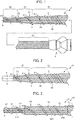
- Fig. 1 shows an overall view of a dilator 1 according to the first embodiment of the present invention.
- the left side in the figure corresponds to the front end side (the distal side) which is to be inserted into the body, and the right side corresponds to the base end side (the hand side, the proximal side) which is to be operated by an operator such as a surgeon.
- a dilator 1 includes a multilayer body 7 including a first coil 3 including a plurality of metal wires wound around into a hollow shape and a second coil 5 including a single metal wire wound around on an outer peripheral surface 3A of the first coil 3 in a direction (clockwise, facing to the front end) opposite to the first coil 3 (counterclockwise, facing to the front end); and a connector 9 having a hollow shape and connected to a base end of the multilayer body 7.
- Wires of the first coil 3 and the second coil 5 are, for example, metal wires of stainless steel, a superelastic alloy such as nickel-titanium, and the like, or resin wires.
- the first coil 3 is configured such that metal wires of, for example, 10 stainless steel wires are wound around.
- the first coil 3 has a hollow shape in which an inner cavity 3B is formed penetratingly extending from a base end to a front end.
- the first coil 3 has a body portion 3C, a tapered portion 3D, and a front end portion 3E.
- the first coil 3 corresponds to a shaft.
- the body portion 3C is located in the base end side of the dilator 1, and the connector 9 is connected to a base end thereof. Further, the body portion 3C has a substantially constant outer diameter from the base end thereof through a front end.
- the tapered portion 3D is located in the front end side of the body portion 3C, and extends to the front end side from the front end of the body portion 3C, and is configured so as to have an outer diameter becoming smaller toward the front end side.
- the tapered portion 3D corresponds to a part of the front end side of the shaft.
- the front end portion 3E is located in the front end side of the tapered portion 3D, and extends to the front end side from a front end of the tapered portion 3D. Further, the front end portion 3E has a substantially constant outer diameter from a base end thereof through a front end. As described above, the first coil 3 which corresponds to a shaft has a hollow shape having an outer diameter of a front end smaller than that of a base end.
- the second coil 5 includes, for example, a single metal wire wound around on the outer peripheral surface 3A of the first coil 3 in a direction (clockwise, facing to the front end) opposite to the first coil 3 (counterclockwise, facing to the front end).
- the metal wire is wound around closely at the base end side, and wound around with gap between adjacent windings at the front end side of the body portion 3C, the tapered portion 3D, and the front end portion 3E.
- a portion of the second coil 5 wound around with gap provides a spirally-arranged protruding portion protruding outwardly (outermost portion of the dilator 1, the outermost surface) on the outer peripheral surface 3A of the first coil 3.
- the above spirally-arranged protruding portion has gaps between adjacent portions (adjacent portions of a metal wire) along an axis A of the first coil 3.
- the screw action of the above spirally-arranged protruding portion enables the dilator 1 to be advanced even by a rotational operation of the dilator 1.
- the second coil 5 at a portion spaced to each other along the axis A is configured so that inclination angles to the axis A of the first coil 3 become gradually smaller toward the tapered portion 3D and the front end portion 3E from the body portion 3C.
- ⁇ 1 to ⁇ 4 in Fig. 1 is such that ⁇ 1 > ⁇ 2 > ⁇ 3 > ⁇ 4. That is, the inclination angle at a second position P2 is configured so as to be smaller than that at a first position P1 along the axis A. It is noted that the second position P2 is located in the front end side relative to the first position P1, and corresponds to a position having an outer diameter smaller than that at the first position P1.
- the amount of gap between adjacent portions of the metal wire is gradually decreased toward the base end side thereof at the body portion 3C.
- This configuration enables the stiffness of the dilator 1 (the multilayer body 7) along the axis direction to be gradually changed so that the dilator 1 can easily enter into an approach pathway even when the pathway meanders.
- the length of a dilator is, for example, 2000 mm, preferably 1600 mm to 2500 mm
- the length of the front end portion 3E is, for example, 10 mm, preferably 0 to 100 mm
- the length of the tapered portion 3D is, for example, 30 mm, preferably 5 to 100 mm.
- the inner diameter of the front end of the first coil 3 is, for example, 0.7 mm, preferably 0.4 to 1.0 mm
- the inner diameter of the base end of the first coil 3 is, for example, 1.5 mm, preferably 1.0 to 3.0 mm.
- the outer diameter of the front end of the second coil 5 is, for example, 1.84 mm, preferably 0.8 to 3.0 mm, and the outer diameter of the base end of the second coil 5 is, for example, 2.64 mm, preferably 1.4 mm to 5.0 mm.
- the diameters of the metal wires of the first coil 3 are, for example, 0.21 mm, preferably 0.1 to 0.5 mm, and the diameter of the metal wire of the second coil 5 is, for example, 0.36 mm, preferably 0.1 to 0.5 mm.
- an inclination angle ( ⁇ 1) of the second coil 5 (the spirally-arranged protruding portion) at the body portion 3C is 70°
- an inclination angle ( ⁇ 4) of the second coil 5 (the spirally-arranged protruding portion) at the front end portion 3E is 60°, and the ratio of them ( ⁇ 1/ ⁇ 4) is 1.17.
- the inclination angle ( ⁇ 1) of the second coil 5 (the spirally-arranged protruding portion) at the body portion 3C is preferably 14 to 87°
- the inclination angle ( ⁇ 1) of the second coil 5 (the spirally-arranged protruding portion) at the front end portion 3E is preferably 7 to 82°
- the ratio of them ( ⁇ 1/ ⁇ 4) preferably ranges from 1.06 to 12.4.
- the connector 9 as a grip portion is a portion through which an operator pushes the dilator into the body, and/or performs a rotational operation.
- a front end of the connector 9 is connected to the base end of the first coil 3 and the base end of the second coil 5.
- the connector 9 is made of a resin, and has a hollow shape having an inner cavity in communication with the inner cavity 3B of the first coil 3.
- the spirally-arranged protruding portion (the second coil 5) protruding outwardly is provided on the outer peripheral surface 3A of the first coil 3 which corresponds to a shaft, and has gaps between adjacent portions along the axis A of the first coil 3.
- This configuration enables the dilator to be advanced not only by a conventional pushing operation, but also by a rotational operation of the spirally-arranged protruding portion.
- the inclination angle at the second position P2 is configured to be smaller than that at the first position P1 along the axis A. It is noted that the second position P2 is located in the front end side relative to the first position P1, and corresponds to a position in which the outer diameter is smaller than that of the first position P1. Therefore, the inclination angles of the spirally-arranged protruding portion are larger at a portion where the outer diameter of the first coil 3 which corresponds to a shaft is relatively large. This enables the spirally-arranged protruding portion to be firmly caught on a target object (for example, the digestive tract such as stomach, and liver). This, in turn, can prevent free rotation of the dilator 1 at the portion where the outer diameter of the first coil 3 which corresponds to a shaft is relatively large.
- a target object for example, the digestive tract such as stomach, and liver
- first coil 3 as a shaft having the tapered portion 3D at a part of the front end side can lead to smooth expansion of a hole.
- a shaft comprised of the first coil 3 including a plurality of metal wires wound around into a hollow shape can improve the flexibility of the shaft and the transmissibility of torque.
- a spirally-arranged protruding portion comprised of the second coil 5 including a single metal wire wound around on the outer peripheral surface 3A of the first coil 3 can be easily formed, and can ensure the flexibility of the front end of the dilator 1 by virtue of the elasticity of the second coil 5, and can improve the torquability.
- wires of the first coil 3 and the second coil 5 are wound around in directions opposite to each other.
- a target object is punctured with an introducer needle to open a hole. Subsequently, a guide wire is inserted into an inner cavity of the introducer needle, and then the introducer needle is withdrawn.
- the base end of the guide wire is inserted into an inner cavity of the above dilator, and then the dilator is inserted. Subsequently, the dilator is pushed in while rotating a shaft to expand the hole at a punctured portion. During this, the tapered portion moves forward by virtue of the screw action of the spirally-arranged protruding portion by a rotational operation of the shaft and others, enabling the tapered portion to smoothly expand the hole.
- Fig. 2 shows a front-end side portion of a dilator 10 according to a second embodiment.
- the left side in the figure corresponds to the front end side (the distal side) which is to be inserted into the body, and the right side corresponds to the base end side (the hand side, the proximal side) which is to be operated by an operator such as a surgeon.
- the dilator 10 according to the present embodiment basically has the same structure as the dilator 1 according to the first embodiment. Therefore, the same number is given to the same member, and detailed description will be omitted.
- a dilator 10 includes a multilayer body 17 including the first coil 3 having a plurality of metal wires wound around into a hollow shape and the second coils 5 having a single metal wire wound around on the outer peripheral surface 3A of the first coil 3 in a direction (clockwise, facing to the front end) opposite to the first coil 3 (counterclockwise, facing to the front end); and a connector 9 having a hollow shape and connected to a base end of the multilayer body 17 (see Fig. 1 ).
- the dilator 10 differs from the dilator 1 in that the dilator 10 has a forefront portion 6 instead of the front end portion 3E of the first coil 3 of the dilator 1.
- the first coil 3 having the forefront portion 6 provided at the front end corresponds to a shaft.
- the forefront portion 6 is formed by casting a solder material (a silver-tin solder material, a gold-tin solder material, and the like) into the front end of the hollow coil body 3, and has a substantially tubular hollow shape. Further, the forefront portion 6 has a flat surface while the front end of the multilayer body 7 has an uneven surface.
- a solder material a silver-tin solder material, a gold-tin solder material, and the like
- the second coil 5 at a portion spaced to each other along the axis A is also configured so that inclination angles to the axis A of the first coil 3 become gradually smaller toward the tapered portion 3D and the front end portion 3E from the body portion 3C.
- ⁇ 1 to ⁇ 3 in Fig. 2 is such that ⁇ 1 > ⁇ 2 > ⁇ 3 as in the first embodiment. That is, the inclination angle at the second position P2 is configured so as to be smaller than that at the first position P1 along the axis A. It is noted that the second position P2 is located in the front end side relative to the first position P1, and corresponds to a position having an outer diameter smaller than that of the first position P1.
- the dilator 10 having this configuration can produce similar effects as the dilator 1 according to the first embodiment. Further, the forefront portion 6 having a flat surface is connected to the front end of the multilayer body 17. This configuration can further improve insertability into a punctured portion by first pressing the dilator against the punctured portion, and then pushing and rotating the dilator thereinto.
- Fig. 3 shows a front-end side portion of a dilator 20 according to a third embodiment.
- the left side in the figure corresponds to the front end side (the distal side) which is to be inserted into the body, and the right side corresponds to the base end side (the hand side, the proximal side) which is to be operated by an operator such as a surgeon.
- the dilator 20 includes a multilayer body 27 including a hollow coil body 21, a coil body 22, a coil body 23, a coil body 24, and a coil body 25; and a connector 9 ( Fig. 1 ) having a hollow shape and connected to a base end of the multilayer body 27.
- the hollow coil body 21 is configured such that a plurality of metal wires (for example, 10 wires) are wound around into a tubular hollow shape.
- the dotted line (the innermost among the three dotted lines) represents the common inscribed line of the hollow coil body 21, and an inner cavity 21B is formed inside the common inscribed line of the hollow coil body 21.
- a front end of the coil body 22 is located in the base end side relative to a front end of the hollow coil body 21, and the coil body 22 is configured such that a plurality of metal wires (for example, 16 wires) are wound around on an outer peripheral surface 21A of the hollow coil body 21 into a tubular hollow shape.
- the plurality of metal wires of the coil body 22 are wound around in the same direction (counterclockwise, facing to the front end) as the hollow coil body 21.
- the dotted line (the intermediate among the three dotted lines) represents the common inscribed line of the hollow coil body 22.
- a front end of the coil body 23 is located at the base end side relative to the front end of the hollow coil body 22, and the coil body 23 is configured such that a plurality of metal wires (for example, 23 wires) are wound around on an outer peripheral surface 22A of the hollow coil body 22 into a tubular hollow shape.
- the plurality of metal wires of the coil body 23 are wound around in a direction (clockwise, facing to the front end) opposite to the coil body 22 (counterclockwise, facing to the front end).
- the dotted line (the outermost among the three dotted lines) represents the common inscribed line of the hollow coil body 23.
- the coil body 22 is twistedly formed on the outer peripheral surface 21A of the hollow coil body 21, and the coil body 23 is twistedly formed on the outer peripheral surface 22A of the coil body 22.
- the hollow coil body 21 and the coil body 22 which correspond to the shaft have a hollow shape having an outer diameter of a front end smaller than that of a base end.
- the coil body 24 is configured such that a single element wire is wound around with gap between adjacent windings on the outer peripheral surface 21A of the coil body 21 in a direction (clockwise, facing to the front end) opposite to the coil body 21 (counterclockwise, facing to the front end).
- the coil body 25 is configured such that a single metal wire is wound around with gap between adjacent windings on the outer peripheral surface 22A of the coil body 22 in a direction (clockwise, facing to the front end) opposite to the coil body 22 (counterclockwise, facing to the front end).
- the multilayer body 27 has a stepped and tubular hollow shape without the tapered portion.
- hollow coil body 21 and the coil body 22 correspond to the shaft and the first coil
- the coil bodies 24 and 25 correspond to the spirally-arranged protruding portion and the second coil.
- each wire is wound around closely while in the coil body 24 and the coil body 25, each wire is wound around with gap between adjacent windings.
- the coil body 24 provides a spirally-arranged protruding portion protruding outwardly (outermost portion of the dilator 20, the outermost surface) on an outer peripheral surface 21L of the hollow coil body 21, and the coil body 25 provides a spirally-arranged protruding portion protruding outwardly (outermost portion of the dilator 20, the outermost surface) on an outer peripheral surface 22T of the coil body 22.
- the above spirally-arranged protruding portions have gaps between adjacent portions (adjacent portions of a metal element wire) along an axis A of the hollow coil body 21.
- wires of the hollow coil body 21, the coil body 22, the coil body 23, the coil body 24, and the coil body 25 may be metal wires made of stainless steel, a superelastic alloy such as nickel-titanium or the like. They shall not be limited to metal wires, but may be resin wires.
- the coil body 24 and the coil body 25 are configured so that inclination angles to the axis A of the hollow coil body 21 and the coil body 22 become gradually smaller from the base end side to the front end side (from the side of the coil body 22 to the side of the hollow coil body 21).
- ⁇ 5 to ⁇ 7 in Fig. 3 is such that ⁇ 5 > ⁇ 6 > ⁇ 7. That is, the inclination angle at a second position P4 is configured so as to be smaller than that at a first position P3 along the axis A. It is noted that the second position P4 is located at the front end side relative to the first position P3, and corresponds to a position having an outer diameter smaller than that of the first position P3.
- the spirally-arranged protruding portions are configured so that the inclination angles are smaller at the second position P4 than at the first position P3 along the axis A.
- the second position P4 is located at the front end side relative to the first position P3, and corresponds to a position having an outer diameter smaller than that of the first position P3. Therefore, the inclination angles of the spirally-arranged protruding portion are larger at the coil body 22 which corresponds a portion where the outer diameter of the shaft is relatively large.
- a target object for example, the digestive tract such as stomach, and liver. This, in turn, can prevent free rotation of the dilator 20 at coil body 22 which corresponds to a portion where the outer diameter of the shaft is relatively large.
- a shaft composed of the hollow coil body 21 and the coil body 22 (the first coil) each including a plurality of metal wires wound around into a hollow shape can improve the flexibility of the shaft and the transmissibility of torque via the shaft.
- a spirally-arranged protruding portion composed of the coil body 24 (the second coil) including a single metal wire wound around on the outer peripheral surface 21A of the hollow coil body 21 and the coil body 25 (the second coil) wound around on the outer peripheral surface 22A of the coil body 22 can be easily formed, and can ensure the flexibility of the front end of the dilator 20 by virtue of the elasticity of the second coil, and can improve the torquability.
- each wire of the hollow coil body 21 and the coil body 22 and each wire of the coil body 24 and the coil body 25 are wound around in directions opposite to each other. Therefore, even when the dilator 20 is rotated in a direction to open the hollow coil body 21 and the coil body 22, a force is applied in a direction to close the coil body 24 and the coil body 25 to prevent opening of the hollow coil body 21 and the coil body 22. This allows a force applied to the connector 9 of the dilator 20 to be transmitted to the front end side.
- Fig. 4 shows an overall view of a dilator 30 according to a fourth embodiment of the present invention.
- the left side in the figure corresponds to the front end side (the distal side) which is to be inserted into the body, and the right side corresponds to the base end side (the hand side, the proximal side) which is to be operated by an operator such as a surgeon.
- the dilator 30 includes a shaft 31, a spirally-arranged protruding portion 32, and a connector 9 connected to a base end of the shaft 31.
- the shaft 31 has a hollow shape in which an inner cavity 31A is formed penetratingly extending from a base end to a front end.
- the shaft 31 also has a body portion 33, a tapered portion 34, and a front end portion 35.
- materials of the shaft 31 and the spirally-arranged protruding portion 32 there is no particular limitation for materials of the shaft 31 and the spirally-arranged protruding portion 32, as long as they can ensure the flexibility of the tapered portion 34 and the front end portion 35 as well as biocompatibility.
- the followings can be used: stainless steel, asuperelastic alloy materials such as nickel-titanium alloys, or synthetic resins such as polyvinyl chloride resin, urethane resin, polyolefin resin, polyamide resin, and fluororesin.
- the body portion 33 is located in the base end side of the dilator 30, and the connector 9 is connected to a base end thereof. Further, the body portion 33 has a substantially constant outer diameter from the base end thereof through the front end.
- the tapered portion 34 is connected to the front end of the body portion 33, and extends from that front end to the front end side, and has a shape tapered toward the front end side. That is, the tapered portion 34 is configured so that the outer shape of the front end side is smaller than that of the base end side.
- the front end portion 35 is connected to a front end of the tapered portion 34 and extends from that front end to the front end side.
- the front end portion 35 has a substantially constant outer diameter from a base end thereof through a front end.
- the shaft 31 has a hollow shape having an outer diameter of the front end smaller than that of the base end.
- the spirally-arranged protruding portion 32 is provided on an outer peripheral surface 31B of the shaft 31 so as to be protruded outwardly (outermost portion of the dilator 30, the outermost surface).
- the spirally-arranged protruding portion 32 is provided at a front-end side portion of the body portion 33, the tapered portion 34, and the front end portion 35, and has gaps between adjacent portions along an axis A of the shaft 31. That is, the adjacent portions of the spirally-arranged protruding portion 32 are spaced to each other.
- the spirally-arranged protruding portion 32 is integrally formed with the shaft 31 by casting and the like.
- the spirally-arranged protruding portion 32 is configured so that inclination angles to the axis A of the shaft 31 become gradually smaller toward the tapered portion 34 and the front end portion 35 from the body portion 33.
- ⁇ 8 to ⁇ 11 in Fig. 4 is such that ⁇ 8 > ⁇ 9 > ⁇ 10 > ⁇ 11. That is, the inclination angle at a second position P6 is configured so as to be smaller than that at a first position P5 along the axis A. It is noted that the second position P6 is located at the front end side relative to the first position P5, and corresponds to a position having an outer diameter smaller than that of the first position P5.
- pitches T1 and T2 of the spirally-arranged protruding portion 32 at the tapered portion 34 are configured to be constant. That is, pitches T1 and T2 between adjacent portions along the axis A of the spirally-arranged protruding portion 32 at the tapered portion 34 are configured to be substantially constant as shown in Fig. 4 .
- the spirally-arranged protruding portion 32 protruding outwardly is provided on the outer peripheral surface 31B of the shaft 31, and has gaps between adjacent portions along the axis A of the shaft 31.
- This configuration enables the dilator to be advanced not only by a conventional pushing operation, but also by a rotational operation of the spirally-arranged protruding portion 32.
- the spirally-arranged protruding portion 32 is configured so that the inclination angles are smaller at the second position P6 than at the first position P5 along the axis A. It is noted that the second position P6 is located at the front end side relative to the first position P5, and corresponds to a position having an outer diameter smaller than that of the first position P5. Therefore, the inclination angles of the spirally-arranged protruding portion 32 are larger at a portion in which the outer diameter of the shaft 31 is relatively large. This enables the spirally-arranged protruding portion 32 to be firmly caught on a target object (for example, the digestive tract such as stomach, and liver). This, in turn, can prevent free rotation of the dilator 30 at the portion in which the outer diameter of the shaft 31 is relatively large.
- a target object for example, the digestive tract such as stomach, and liver
- the shaft 31 having the tapered portion 34 at a part of the front end side can lead to smooth expansion of a hole.
- the inclination angles of the spirally-arranged protruded portion 32 are larger at a portion in which the outer diameter of the shaft 31 is relatively large. This enables the spirally-arranged protruding portion 32 to be firmly caught on a target object (for example, the digestive tract such as stomach, and liver) to prevent free rotation of the dilator 30.
- pitches T1 and T2 of the spirally-arranged protruding portion 32 at the tapered portion 34 are configured to be constant. This enables a distance of advance to be maintained constant at the tapered portion 34 when the dilator 30 is rotationally operated.
- Fig. 5 shows a front-end side portion of a dilator 40 according to a fifth embodiment.
- the left side in the figure corresponds to the front end side (the distal side) which is to be inserted into the body, and the right side corresponds to the base end side (the hand side, the proximal side) which is to be operated by an operator such as a surgeon.
- the dilator 40 includes a shaft 41, a spirally-arranged protruding portion 42, and a connector 9 connected to a base end of the shaft 41 (see Fig. 4 ).
- the material(s) of the shaft 41 and the spirally-arranged protruding portion 42 is/are the same as that/those of the shaft 31 and the spirally-arranged protruding portion 32 of the dilator 30 according to the ninth embodiment.
- the shaft 41 has a hollow shape in which an inner cavity 41A is formed penetratingly extending from a base end to a front end.
- the shaft 41 has a body portion 43 and a tapered portion 44.
- the dilator 40 according to the present embodiment differs from the dilator 30 according to the fourth embodiment in that the dilator 40 does not have the front end portion.
- the body portion 43 and the tapered portion 44 have the same configurations as the body portion 33 and the tapered portion 34 according to the fourth embodiment.
- the spirally-arranged protruding portion 42 is provided on an outer peripheral surface 41B of the shaft 41 so as to be protruding outwardly (outermost portion of the dilator 40, the outermost surface).
- the spirally-arranged protruding portion 42 is provided at a front-end side portion of the body portion 43 and the tapered portion 44, and has gaps between adjacent portions along an axis A of the shaft 41. That is, the adjacent portions of the spirally-arranged protruding portion 42 are spaced to each other.
- the spirally-arranged protruding portion 42 is integrally formed with the shaft 41 by casting and the like.
- the spirally-arranged protruding portion 42 is configured so that inclination angles to the axis A of the shaft 41 become gradually smaller toward the tapered portion 44 and the front end portion 45 from the body portion 43.
- ⁇ 12 to ⁇ 14 in Fig. 5 are such that ⁇ 12 > ⁇ 13 > ⁇ 14. That is, the inclination angle at a second position P8 is configured so as to be smaller than that at a first position P7 along the axis A. It is noted that the second position P8 is located at the front end side relative to the first position P7, and corresponds to a position having an outer diameter smaller than that of the first position P7.
- pitches T3 and T4 of the spirally-arranged protruding portion 42 at the tapered portion 44 are configured to be constant. That is, the pitches T3 and T4 between adjacent portions of the spirally-arranged protruding portion 42 at the tapered portion 34 are configured to be substantially constant as shown in Fig. 4 .
- the spirally-arranged protruding portion 42 protruding outwardly is provided on the outer peripheral surface 41B of the shaft 41, and has gaps between adjacent portions along the axis A of the shaft 41.
- This configuration enables the dilator to be advanced not only by a conventional pushing operation, but also by a rotational operation of the spirally-arranged protruding portion 42.
- the spirally-arranged protruding portion 42 is configured so that the inclination angles are smaller at the second position P8 than at the first position P7 along the axis A.
- the second position P8 is located at the front end side relative to the first position P7, and corresponds to a position having an outer diameter smaller than that of the first position P7. Therefore, the inclination angles of the spirally-arranged protruding portion are larger at a portion in which the outer diameter of the shaft 41 is relatively large. This enables the spirally-arranged protruding portion 42 to be firmly caught on a target object (for example, the digestive tract such as stomach, and liver). This, in turn, can prevent free rotation of the dilator 40 at the portion in which the outer diameter of the shaft 41 is relatively large.
- a target object for example, the digestive tract such as stomach, and liver
- the shaft 41 having the tapered portion 44 at a part of the front end side can lead to smooth expansion of a hole.
- the inclination angles of the spirally-arranged protruding portion 42 are larger at a portion in which the outer diameter of the shaft 41 is relatively large. This enables the spirally-arranged protruding portion 42 to be firmly caught on a target object (for example, the digestive tract such as stomach, and liver) to prevent free rotation of the dilator 40.
- pitches T3 and T4 of the spirally-arranged protruding portion 42 at the tapered portion 44 are configured be constant. This enables a distance of advance to be maintained constant at the tapered portion 44 when the dilator 40 is rotationally operated.
- Fig. 6 shows a front-end side portion of a dilator 50 according to a sixth embodiment.
- the left side in the figure corresponds to the front end side (the distal side) which is to be inserted into the body, and the right side corresponds to the base end side (the hand side, the proximal side) which is to be operated by an operator such as a surgeon.
- the dilator 50 includes a shaft 51, a spirally-arranged protruding portion 52, and a connector 9 connected to a base end of the shaft 51 (see Fig. 4 ).
- the material(s) of the shaft 51 and the spirally-arranged protruding portion 52 is/are the same as that/those of the shaft 31 and the spirally-arranged protruding portion 32 of the dilator 30 according to the fourth embodiment.
- the shaft 51 has a hollow shape in which an inner cavity 51A is formed penetratingly extending from a base end to a front end.
- the shaft 51 also has a tapered portion 54.
- the dilator 50 according to the present embodiment differs from the dilator 30 according to the fourth embodiment in that the dilator 50 does not have the front end portion nor the body portion. That is, the shaft 51 according to the present embodiment has a tapered shape having an outer diameter gradually decreasing from a base end to a front end throughout the entire length. This means that the shaft 51 has a hollow shape having an outer diameter of the front end smaller than that of the base end.
- the spirally-arranged protruding portion 52 is provided on an outer peripheral surface 51B of the shaft 51 so as to be protruded outwardly (outermost portion of the dilator 50, the outermost surface).
- the spirally-arranged protruding portion 52 is provided at a front-end side portion of the tapered portion 54, and has gaps between adjacent portions along an axis A of the shaft 51. That is, the adjacent portions of the spirally-arranged protruding portion 52 are spaced to each other.
- the spirally-arranged protruding portion 52 is integrally formed with the shaft 51 by casting and the like.
- the spirally-arranged protruding portion 52 is configured so that inclination angles to the axis A of the shaft 51 become gradually smaller toward the front end side from the base end side at the tapered portion 54.
- ⁇ 15 to ⁇ 17 in Fig. 6 are such that ⁇ 15 > ⁇ 16 > ⁇ 17. That is, the inclination angle at a second position P10 is configured so as to be smaller than that at a first position P9 along the axis A. It is noted that the second position P10 is located in the front end side relative to the first position P9, and is a position having an outer diameter smaller than that of the first position P9.
- pitches T5, T6, and T7 of the spirally-arranged protruding portion 52 at the tapered portion 54 are configured to be constant. That is, the pitches T5, T6, and T7 between adjacent portions of the spirally-arranged protruding portion 52 at the tapered portion 54 are configured to be constant as shown in Fig. 6 . It is noted that in Fig. 6 , pitches of the spirally-arranged protruding portions 52 at portions other than these having pitches indicated are also configured to be constant.
- the spirally-arranged protruding portion 52 protruding outwardly is provided on the outer peripheral surface 51B of the shaft 51, and has gaps between adjacent portions along the axis A of the shaft 51.
- This configuration enables the dilator to be advanced not only by a conventional pushing operation, but also by a rotational operation of the spirally-arranged protruding portion 52.
- the spirally-arranged protruding portion 52 is configured so that the inclination angles are smaller at the second position P10 than at the first position P9 along the axis A.
- the second position P10 is located at the front end side relative to the first position P9, and is a position having an outer diameter smaller than that of the first position P9. Therefore, the inclination angles of the spirally-arranged protruding portion are larger at a portion in which the outer diameter of the shaft 51 is relatively large. This enables the spirally-arranged protruding portion 42 to be firmly caught on a target object (for example, the digestive tract such as stomach, and liver). This, in turn, can prevent free rotation of the dilator 50 at the portion in which the outer diameter of the shaft 51 is relatively large.
- a target object for example, the digestive tract such as stomach, and liver
- the shaft 51 having the tapered portion 54 can lead to smooth expansion of a hole.
- the inclination angles of the spirally-arranged protruding portion 52 are larger at a portion in which the outer diameter of the shaft 51 is relatively large. This enables the spirally-arranged protruding portion 52 to be firmly caught on a target object (for example, the digestive tract such as stomach, and liver) to prevent free rotation of the dilator 50.
- pitches T5, T6, and T7 of the spirally-arranged protruding portion 52 at the tapered portion 54 are configured to be constant. This enables a distance of advance to be maintained constant at the tapered portion 54 when the dilator 50 is rotationally operated.
- Fig. 7 shows a front-end side portion of a dilator 60 according to a seventh embodiment.
- the left side in the figure corresponds to the front end side (the distal side) which is to be inserted into the body
- the right side corresponds to the base end side (the hand side, the proximal side) which is to be operated by an operator such as a surgeon.
- the same reference number is given to the same member as the third embodiment, and description thereof is omitted.
- the dilator 60 includes the shaft 31, a spirally-arranged protruding portion 62, and the connector 9 connected to the base end of the shaft 31.
- the spirally-arranged protruding portion 62 is provided on the outer peripheral surface 31B of the shaft 31 so as to be protruded outwardly (outermost portion of the dilator 30, the outermost surface).
- the spirally-arranged protruding portion 62 is provided at a front-end side portion of the body portion 33, the tapered portion 34, and the front end portion 35, and has gaps between adjacent portions along the axis A of the shaft 31. That is, the adjacent portions of the spirally-arranged protruding portion 62 are spaced to each other.
- the spirally-arranged protruding portion 62 is integrally formed with the shaft 31 by casting and the like.
- the spirally-arranged protruding portion 62 is configured so that the inclination angles to the axis A of the shaft 31 become gradually larger toward the tapered portion 34 and the front end portion 35 from the body portion 33.
- ⁇ 18 to ⁇ 21 in Fig. 7 are such that ⁇ 18 ⁇ ⁇ 19 ⁇ ⁇ 20 ⁇ ⁇ 21. That is, the inclination angle at a second position P12 is configured to be larger than that at a first position P11 along the axis A. It is noted that the second position P12 is located at the front end side relative to the first position P11, and is a position having an outer diameter smaller than that of the first position P11.
- the spirally-arranged protruding portion 62 protruding outwardly is provided on the outer peripheral surface 31B of the shaft 31, and has gaps between adjacent portions along the axis A of the shaft 31.
- This configuration enables the dilator to be advanced not only by a conventional pushing operation, but also by a rotational operation of the spirally-arranged protruding portion 62.
- the spirally-arranged protruding portion 62 is configured so that the inclination angles are larger at the second position P12 than at the first position P11 along the axis A.
- the second position P12 is located in the front end side relative to the first position P11, and is a position having an outer diameter smaller than that of the first position P11. Therefore, the inclination angles of the spirally-arranged protruding portion are larger at a portion in which the outer diameter of the shaft 31 is relatively small.
- a target object for example, the digestive tract such as stomach, and liver. This, in turn, can prevent free rotation of the dilator 60 at the portion in which the outer diameter of the shaft 31 is relatively small.
- the shaft 31 having the tapered portion 34 at a part of the front end side can lead to smooth expansion of a hole.
- the inclination angles of the spirally-arranged protruding portion 62 are larger at a portion in which the outer diameter of the shaft 31 is relatively small. This enables the spirally-arranged protruding portion 62 to be firmly caught on a target object (for example, the digestive tract such as stomach, and liver) to prevent free rotation of the dilator 60.
- the first coils 3 and 21 are each described as a hollow coil body including 10 wires in the aforementioned embodiments, but the number of wires shall not be limited to 10. The number may be one or more.
- the coil body 22 is described as a coil body including 16 wires in the aforementioned embodiments, but the number of wires shall not be limited to 16. The number may be one or more.
- the coil body 23 is described as a coil body including 23 wires in the aforementioned embodiments, but the number of wires shall not be limited to 23. The number may be one or more.
- the forefront portion 6 according to the second embodiment is described to be formed by casting a solder material into the front end of the multilayer body 17.
- the outer periphery of the second coil 5 and/or the first coil 3 in the vicinity of the front end portion of the multilayer body 17 may be ground to form the forefront portion 6 having a flat surface.
- the forefront portion 6 according to the second embodiment is described to be fixed to the front end of the multilayer body 17, but the forefront portion may be fixed to the front end of the multilayer body 27 according to the third embodiment, the front end of the shaft 31 according to the fourth embodiment, the front end of the shaft 41 according to the fifth embodiment, and the front end of the shaft 51 according to the sixth embodiment.
- the outer peripheries of the multilayer bodies 7, 17, and 27 according to the first to third embodiments, and the shafts 31, 41, 51, and 61 according to the fourth to seventh embodiments, and the spirally-arranged protruding portions 32, 42, 52, and 62 may be coated with a resin (s) .
- a resin s
- the outer peripheries of the shaft 31 and the spirally-arranged protruding portion 32 of the dilator 30 according to the fourth embodiment may be coated with a resin 36.
- the resin 36 can improve slidability to prevent biting of a living body tissue.
- the resin 36 When the outer periphery of the shaft 31 is coated with the resin 36, a portion where the body portion 33, the tapered portion 34, and the front end portion 35 are coated with the resin 36 corresponds to the shaft 31, and a portion protruding outwardly from the outer peripheral surface 31B of the above shaft 31 corresponds to the spirally-arranged protruding portion 32.
- the resin 36 include, for example, biocompatible resin materials such as polyamide resin and fluororesin, or hydrophilic coating materials, and the like.
- the resin 36 has a thickness of, for example, 0.1 to 300 ⁇ m.
- the shafts 31, 41, and 51 and the spiral protruding portions 32, 42, and 52 are configured integrally, but may be configured as separate bodies.
- the second coils 5, 24, and 25 and the spirally-arranged protruding portions 32, 42, 52, and 62 are configured so that the inclination angles are gradually decreased in the above embodiments, but the inclination angles are configured to be stepwisely decreased.
- the shafts 31, 41, and 51 and the spiral protruding portions 32, 42, 52, and 62 are configured integrally, but may be configured as separate bodies.
- first positions P1, P3, P5, P7, P9, and P11 and the second positions P2, P4, P6, P8, P10, and P12 are not limited to the positions in the above embodiments, but the first and second positions may be located at any positions as long as the second position is located in the front end side relative to the first position, and has outer diameter smaller than that of the first position.
- dilators each including a shaft having no surface coating.
- the shaft may have various types of coating on the side of the surface thereof (including a portion between the shaft and the spirally-arranged protruding portion).
- the coating include, for example, a protective film on the surface of the shaft (representative example: a plating film), an underlying film for improving adhesiveness between the shaft and the spirally-arranged protruding portion, and the like.
- the spirally-arranged protruding portions according to the embodiments as shown in Figs. 1 to 8 are not configured to serve as a blade.
- the dilators according to the present embodiments are intended for expanding a hole pre-formed on a target object (for example, the wall of the digestive tract such as the patient's stomach). Therefore, if the spirally-arranged protruding portion serves as a blade, living body tissues at the inner surface of the hole may be damaged.
- the spirally-arranged protruding portion preferably does not have a sharp edge at an end portion in a radially outer side of the shaft on a cross-section (for example, on a cross-section perpendicular to the spiral direction of the spirally-arranged protruding portion as shown in Fig. 4 ). That is, the above end portion preferably has an area having a shape including an obtuse angle or a curve (for example, a curve constituting a part of a circle or an ellipse).
Landscapes
- Health & Medical Sciences (AREA)
- Life Sciences & Earth Sciences (AREA)
- Veterinary Medicine (AREA)
- Public Health (AREA)
- Engineering & Computer Science (AREA)
- Biomedical Technology (AREA)
- Heart & Thoracic Surgery (AREA)
- Animal Behavior & Ethology (AREA)
- General Health & Medical Sciences (AREA)
- Anesthesiology (AREA)
- Hematology (AREA)
- Surgery (AREA)
- Pulmonology (AREA)
- Biophysics (AREA)
- Pathology (AREA)
- Nuclear Medicine, Radiotherapy & Molecular Imaging (AREA)
- Medical Informatics (AREA)
- Molecular Biology (AREA)
- Dermatology (AREA)
- Oral & Maxillofacial Surgery (AREA)
- Media Introduction/Drainage Providing Device (AREA)
- Surgical Instruments (AREA)
- Prostheses (AREA)
- Gasket Seals (AREA)
Abstract
Description
- The present invention relates to a dilator.
- Dilators are known for expanding a hole formed on the wall of the patient's digestive tract and the like for the purpose of treatment. A front end of a dilator is inserted into the hole formed on a wall, and a tapered portion is then pushed into the hole to expand the hole. Such a dilator is disclosed in, for example, Patent Literature 1.
- Patent Literature 1: Japanese Patent Application Laid-Open No
2008-11867 - When the dilator described above is very long, a rotational force and a pushing force from the hand side may not be well transmitted to the front end of the dilator, and thus a hole formed on the wall of the digestive tract cannot be sufficiently expanded.
- An object of the present invention is to provide a dilator capable of easily increasing the diameter of a hole formed on the wall of the digestive tract and the like.
- In order to achieve the above object, a dilator according to an aspect of the present invention includes a hollow shaft having an outer diameter of a front end smaller than that of a base end; and a grip portion provided at the base end of the shaft. A spirally-arranged protruding portion protruding outwardly is provided on an outer peripheral surface of the shaft, and has gaps between adjacent portions along an axis of the shaft. The shaft has a first position and a second position along the axis, the second position being located at a front end side relative to the first position and having an outer diameter smaller than that of the first position, and the spirally-arranged protruding portion has an inclination angle to the axis at the second position smaller than that at the first position.
- Further, a part of the front end side of the shaft may have a tapered shape having an outer diameter decreasing toward the front end side.
- Further, pitches of the spirally-arranged protruding portion may be constant at the part of the front end side of the shaft having a tapered shape.
- Further, the shaft may include a first coil having a wire wound around into a hollow shape.
- Further, the spirally-arranged protruding portion may include a second coil having a wire wound around on the outer peripheral surface of the shaft.
- Further, the shaft includes the first coil having a wire wound around into a hollow shape, and the spirally-arranged protruding portion includes the second coil having a wire wound around on the outer peripheral surface of the shaft, and wires of the first coil and the second coil may be wound around in directions opposite to each other.
- Further, a dilator according to another aspect of the present invention includes a hollow shaft having an outer diameter of a front end smaller than that of a base end; and a grip portion provided at the base end of the shaft. A spirally-arranged protruding portion is provided on an outer peripheral surface of the shaft, and has gaps between adjacent portions along an axis of the shaft. The shaft has a first position and a second position along the axis, the second position being located at a front end side relative to the first position and having an outer diameter smaller than that of the first position, and the spirally-arranged protruding portion has an inclination angle to the axis at the second position is larger than that at the first position.
- The present invention can provide a dilator capable of easily increasing the diameter of a hole formed on the wall of the digestive tract and the like.
-
-
Fig. 1 shows an overall view of a dilator according to a first embodiment of the present invention. -
Fig. 2 shows a front-end side portion of a dilator according to a second embodiment. -
Fig. 3 shows a front-end side portion of a dilator according to a third embodiment. -
Fig. 4 shows an overall view of a dilator according to a fourth embodiment. -
Fig. 5 shows a front-end side portion of a dilator according to a fifth embodiment. -
Fig. 6 shows a front-end side portion of a dilator according to a sixth embodiment. -
Fig. 7 shows a partial cross-sectional view of a front-end side portion of a dilator according to a seventh embodiment. -
Fig. 8 shows a front-end side portion of a dilator according to a modified example. - Below, the embodiments of the present invention will be described with reference to the figures. It is noted that the dimensions of dilators shown in the figures are merely provided to facilitate understanding of the embodiments, but do not necessarily correspond to the actual dimensions.
- A first embodiment of the present invention will be described with reference to the figures.
-
Fig. 1 shows an overall view of a dilator 1 according to the first embodiment of the present invention. - In
Fig. 1 , the left side in the figure corresponds to the front end side (the distal side) which is to be inserted into the body, and the right side corresponds to the base end side (the hand side, the proximal side) which is to be operated by an operator such as a surgeon. - In
Fig. 1 , a dilator 1 includes a multilayer body 7 including afirst coil 3 including a plurality of metal wires wound around into a hollow shape and a second coil 5 including a single metal wire wound around on an outerperipheral surface 3A of thefirst coil 3 in a direction (clockwise, facing to the front end) opposite to the first coil 3 (counterclockwise, facing to the front end); and a connector 9 having a hollow shape and connected to a base end of the multilayer body 7. - Wires of the
first coil 3 and the second coil 5 are, for example, metal wires of stainless steel, a superelastic alloy such as nickel-titanium, and the like, or resin wires. - The
first coil 3 is configured such that metal wires of, for example, 10 stainless steel wires are wound around. Thefirst coil 3 has a hollow shape in which aninner cavity 3B is formed penetratingly extending from a base end to a front end. Thefirst coil 3 has abody portion 3C, atapered portion 3D, and afront end portion 3E. Thefirst coil 3 corresponds to a shaft. - The
body portion 3C is located in the base end side of the dilator 1, and the connector 9 is connected to a base end thereof. Further, thebody portion 3C has a substantially constant outer diameter from the base end thereof through a front end. - The
tapered portion 3D is located in the front end side of thebody portion 3C, and extends to the front end side from the front end of thebody portion 3C, and is configured so as to have an outer diameter becoming smaller toward the front end side. Thetapered portion 3D corresponds to a part of the front end side of the shaft. - The
front end portion 3E is located in the front end side of thetapered portion 3D, and extends to the front end side from a front end of thetapered portion 3D. Further, thefront end portion 3E has a substantially constant outer diameter from a base end thereof through a front end. As described above, thefirst coil 3 which corresponds to a shaft has a hollow shape having an outer diameter of a front end smaller than that of a base end. - The second coil 5 includes, for example, a single metal wire wound around on the outer
peripheral surface 3A of thefirst coil 3 in a direction (clockwise, facing to the front end) opposite to the first coil 3 (counterclockwise, facing to the front end). Here, the metal wire is wound around closely at the base end side, and wound around with gap between adjacent windings at the front end side of thebody portion 3C, thetapered portion 3D, and thefront end portion 3E. A portion of the second coil 5 wound around with gap provides a spirally-arranged protruding portion protruding outwardly (outermost portion of the dilator 1, the outermost surface) on the outerperipheral surface 3A of thefirst coil 3. The above spirally-arranged protruding portion has gaps between adjacent portions (adjacent portions of a metal wire) along an axis A of thefirst coil 3. The screw action of the above spirally-arranged protruding portion enables the dilator 1 to be advanced even by a rotational operation of the dilator 1. - Further, the second coil 5 at a portion spaced to each other along the axis A is configured so that inclination angles to the axis A of the
first coil 3 become gradually smaller toward thetapered portion 3D and thefront end portion 3E from thebody portion 3C. In the present embodiment, θ1 to θ4 inFig. 1 is such that θ1 > θ2 > θ3 > θ4. That is, the inclination angle at a second position P2 is configured so as to be smaller than that at a first position P1 along the axis A. It is noted that the second position P2 is located in the front end side relative to the first position P1, and corresponds to a position having an outer diameter smaller than that at the first position P1. - Further, with regard to the metal wire of the second coil 5, the amount of gap between adjacent portions of the metal wire is gradually decreased toward the base end side thereof at the
body portion 3C. This configuration enables the stiffness of the dilator 1 (the multilayer body 7) along the axis direction to be gradually changed so that the dilator 1 can easily enter into an approach pathway even when the pathway meanders. - In the present embodiment and other embodiments described hereinafter, the length of a dilator is, for example, 2000 mm, preferably 1600 mm to 2500 mm, and the length of the
front end portion 3E is, for example, 10 mm, preferably 0 to 100 mm, and the length of thetapered portion 3D is, for example, 30 mm, preferably 5 to 100 mm. The inner diameter of the front end of thefirst coil 3 is, for example, 0.7 mm, preferably 0.4 to 1.0 mm, and the inner diameter of the base end of thefirst coil 3 is, for example, 1.5 mm, preferably 1.0 to 3.0 mm. The outer diameter of the front end of the second coil 5 is, for example, 1.84 mm, preferably 0.8 to 3.0 mm, and the outer diameter of the base end of the second coil 5 is, for example, 2.64 mm, preferably 1.4 mm to 5.0 mm. Further, the diameters of the metal wires of thefirst coil 3 are, for example, 0.21 mm, preferably 0.1 to 0.5 mm, and the diameter of the metal wire of the second coil 5 is, for example, 0.36 mm, preferably 0.1 to 0.5 mm. - Further, an inclination angle (θ1) of the second coil 5 (the spirally-arranged protruding portion) at the
body portion 3C is 70°, and an inclination angle (θ4) of the second coil 5 (the spirally-arranged protruding portion) at thefront end portion 3E is 60°, and the ratio of them (θ1/θ4) is 1.17. It is noted that the inclination angle (θ1) of the second coil 5 (the spirally-arranged protruding portion) at thebody portion 3C is preferably 14 to 87°, and the inclination angle (θ1) of the second coil 5 (the spirally-arranged protruding portion) at thefront end portion 3E is preferably 7 to 82°, and the ratio of them (θ1/θ4) preferably ranges from 1.06 to 12.4. - The connector 9 as a grip portion is a portion through which an operator pushes the dilator into the body, and/or performs a rotational operation. A front end of the connector 9 is connected to the base end of the
first coil 3 and the base end of the second coil 5. The connector 9 is made of a resin, and has a hollow shape having an inner cavity in communication with theinner cavity 3B of thefirst coil 3. - In the dilator 1 according to the present embodiment, the spirally-arranged protruding portion (the second coil 5) protruding outwardly is provided on the outer
peripheral surface 3A of thefirst coil 3 which corresponds to a shaft, and has gaps between adjacent portions along the axis A of thefirst coil 3. This configuration enables the dilator to be advanced not only by a conventional pushing operation, but also by a rotational operation of the spirally-arranged protruding portion. - Further, for the spirally-arranged protruding portion (the second coil 5) of the dilator 1 according to the present embodiment, the inclination angle at the second position P2 is configured to be smaller than that at the first position P1 along the axis A. It is noted that the second position P2 is located in the front end side relative to the first position P1, and corresponds to a position in which the outer diameter is smaller than that of the first position P1. Therefore, the inclination angles of the spirally-arranged protruding portion are larger at a portion where the outer diameter of the
first coil 3 which corresponds to a shaft is relatively large. This enables the spirally-arranged protruding portion to be firmly caught on a target object (for example, the digestive tract such as stomach, and liver). This, in turn, can prevent free rotation of the dilator 1 at the portion where the outer diameter of thefirst coil 3 which corresponds to a shaft is relatively large. - Further, the
first coil 3 as a shaft having the taperedportion 3D at a part of the front end side can lead to smooth expansion of a hole. - Further, a shaft comprised of the
first coil 3 including a plurality of metal wires wound around into a hollow shape can improve the flexibility of the shaft and the transmissibility of torque. Further, a spirally-arranged protruding portion comprised of the second coil 5 including a single metal wire wound around on the outerperipheral surface 3A of thefirst coil 3 can be easily formed, and can ensure the flexibility of the front end of the dilator 1 by virtue of the elasticity of the second coil 5, and can improve the torquability. Further, wires of thefirst coil 3 and the second coil 5 are wound around in directions opposite to each other. Therefore, even when the dilator 1 is rotated in a direction to open thefirst coil 3, a force is applied in a direction to close the second coil 5 to prevent opening of thefirst coil 3. This allows a force applied to the connector 9 of the dilator 1 to be transmitted to the front end side. - Next, an example of operating modes of the above dilator will be described.
- First, a target object is punctured with an introducer needle to open a hole. Subsequently, a guide wire is inserted into an inner cavity of the introducer needle, and then the introducer needle is withdrawn.
- Next, the base end of the guide wire is inserted into an inner cavity of the above dilator, and then the dilator is inserted. Subsequently, the dilator is pushed in while rotating a shaft to expand the hole at a punctured portion. During this, the tapered portion moves forward by virtue of the screw action of the spirally-arranged protruding portion by a rotational operation of the shaft and others, enabling the tapered portion to smoothly expand the hole.
-
Fig. 2 shows a front-end side portion of adilator 10 according to a second embodiment. - In
Fig. 2 , the left side in the figure corresponds to the front end side (the distal side) which is to be inserted into the body, and the right side corresponds to the base end side (the hand side, the proximal side) which is to be operated by an operator such as a surgeon. - It is noted that the
dilator 10 according to the present embodiment basically has the same structure as the dilator 1 according to the first embodiment. Therefore, the same number is given to the same member, and detailed description will be omitted. - In
Fig. 2 , adilator 10 includes amultilayer body 17 including thefirst coil 3 having a plurality of metal wires wound around into a hollow shape and the second coils 5 having a single metal wire wound around on the outerperipheral surface 3A of thefirst coil 3 in a direction (clockwise, facing to the front end) opposite to the first coil 3 (counterclockwise, facing to the front end); and a connector 9 having a hollow shape and connected to a base end of the multilayer body 17 (seeFig. 1 ). However, thedilator 10 differs from the dilator 1 in that thedilator 10 has a forefront portion 6 instead of thefront end portion 3E of thefirst coil 3 of the dilator 1. According to the present embodiment, thefirst coil 3 having the forefront portion 6 provided at the front end corresponds to a shaft. - The forefront portion 6 is formed by casting a solder material (a silver-tin solder material, a gold-tin solder material, and the like) into the front end of the
hollow coil body 3, and has a substantially tubular hollow shape. Further, the forefront portion 6 has a flat surface while the front end of the multilayer body 7 has an uneven surface. - In the present embodiment, the second coil 5 at a portion spaced to each other along the axis A is also configured so that inclination angles to the axis A of the
first coil 3 become gradually smaller toward the taperedportion 3D and thefront end portion 3E from thebody portion 3C. In the present embodiment, θ1 to θ3 inFig. 2 is such that θ1 > θ2 > θ3 as in the first embodiment. That is, the inclination angle at the second position P2 is configured so as to be smaller than that at the first position P1 along the axis A. It is noted that the second position P2 is located in the front end side relative to the first position P1, and corresponds to a position having an outer diameter smaller than that of the first position P1. - The
dilator 10 having this configuration can produce similar effects as the dilator 1 according to the first embodiment. Further, the forefront portion 6 having a flat surface is connected to the front end of themultilayer body 17. This configuration can further improve insertability into a punctured portion by first pressing the dilator against the punctured portion, and then pushing and rotating the dilator thereinto. -
Fig. 3 shows a front-end side portion of adilator 20 according to a third embodiment. - In
Fig. 3 , the left side in the figure corresponds to the front end side (the distal side) which is to be inserted into the body, and the right side corresponds to the base end side (the hand side, the proximal side) which is to be operated by an operator such as a surgeon. - In
Fig. 3 , thedilator 20 includes amultilayer body 27 including ahollow coil body 21, acoil body 22, acoil body 23, acoil body 24, and acoil body 25; and a connector 9 (Fig. 1 ) having a hollow shape and connected to a base end of themultilayer body 27. - The
hollow coil body 21 is configured such that a plurality of metal wires (for example, 10 wires) are wound around into a tubular hollow shape. InFig. 3 , the dotted line (the innermost among the three dotted lines) represents the common inscribed line of thehollow coil body 21, and aninner cavity 21B is formed inside the common inscribed line of thehollow coil body 21. - A front end of the
coil body 22 is located in the base end side relative to a front end of thehollow coil body 21, and thecoil body 22 is configured such that a plurality of metal wires (for example, 16 wires) are wound around on an outerperipheral surface 21A of thehollow coil body 21 into a tubular hollow shape. The plurality of metal wires of thecoil body 22 are wound around in the same direction (counterclockwise, facing to the front end) as thehollow coil body 21. InFig. 3 , the dotted line (the intermediate among the three dotted lines) represents the common inscribed line of thehollow coil body 22. - A front end of the
coil body 23 is located at the base end side relative to the front end of thehollow coil body 22, and thecoil body 23 is configured such that a plurality of metal wires (for example, 23 wires) are wound around on an outerperipheral surface 22A of thehollow coil body 22 into a tubular hollow shape. The plurality of metal wires of thecoil body 23 are wound around in a direction (clockwise, facing to the front end) opposite to the coil body 22 (counterclockwise, facing to the front end). InFig. 3 , the dotted line (the outermost among the three dotted lines) represents the common inscribed line of thehollow coil body 23. - The
coil body 22 is twistedly formed on the outerperipheral surface 21A of thehollow coil body 21, and thecoil body 23 is twistedly formed on the outerperipheral surface 22A of thecoil body 22. This means that thehollow coil body 21 and thecoil body 22 which correspond to the shaft have a hollow shape having an outer diameter of a front end smaller than that of a base end. - The
coil body 24 is configured such that a single element wire is wound around with gap between adjacent windings on the outerperipheral surface 21A of thecoil body 21 in a direction (clockwise, facing to the front end) opposite to the coil body 21 (counterclockwise, facing to the front end). Thecoil body 25 is configured such that a single metal wire is wound around with gap between adjacent windings on the outerperipheral surface 22A of thecoil body 22 in a direction (clockwise, facing to the front end) opposite to the coil body 22 (counterclockwise, facing to the front end). - In the present embodiment, the
multilayer body 27 has a stepped and tubular hollow shape without the tapered portion. - It is noted that the
hollow coil body 21 and thecoil body 22 correspond to the shaft and the first coil, and thecoil bodies - According to the present embodiment, in the
hollow coil body 21, thecoil body 22, and thecoil body 23, each wire is wound around closely while in thecoil body 24 and thecoil body 25, each wire is wound around with gap between adjacent windings. Thecoil body 24 provides a spirally-arranged protruding portion protruding outwardly (outermost portion of thedilator 20, the outermost surface) on an outer peripheral surface 21L of thehollow coil body 21, and thecoil body 25 provides a spirally-arranged protruding portion protruding outwardly (outermost portion of thedilator 20, the outermost surface) on an outer peripheral surface 22T of thecoil body 22. The above spirally-arranged protruding portions have gaps between adjacent portions (adjacent portions of a metal element wire) along an axis A of thehollow coil body 21. - It is noted that in the present embodiment, wires of the
hollow coil body 21, thecoil body 22, thecoil body 23, thecoil body 24, and thecoil body 25 may be metal wires made of stainless steel, a superelastic alloy such as nickel-titanium or the like. They shall not be limited to metal wires, but may be resin wires. - Further, the
coil body 24 and thecoil body 25 are configured so that inclination angles to the axis A of thehollow coil body 21 and thecoil body 22 become gradually smaller from the base end side to the front end side (from the side of thecoil body 22 to the side of the hollow coil body 21). In the present embodiment, θ5 to θ7 inFig. 3 is such that θ5 > θ6 > θ7. That is, the inclination angle at a second position P4 is configured so as to be smaller than that at a first position P3 along the axis A. It is noted that the second position P4 is located at the front end side relative to the first position P3, and corresponds to a position having an outer diameter smaller than that of the first position P3. - In the
dilator 20 according to the present embodiment, the spirally-arranged protruding portions (thecoil bodies 24 and 25) are configured so that the inclination angles are smaller at the second position P4 than at the first position P3 along the axis A. It is noted that the second position P4 is located at the front end side relative to the first position P3, and corresponds to a position having an outer diameter smaller than that of the first position P3. Therefore, the inclination angles of the spirally-arranged protruding portion are larger at thecoil body 22 which corresponds a portion where the outer diameter of the shaft is relatively large. This enables the spirally-arranged protruding portion to be firmly caught on a target object (for example, the digestive tract such as stomach, and liver). This, in turn, can prevent free rotation of thedilator 20 atcoil body 22 which corresponds to a portion where the outer diameter of the shaft is relatively large. - Further, a shaft composed of the
hollow coil body 21 and the coil body 22 (the first coil) each including a plurality of metal wires wound around into a hollow shape can improve the flexibility of the shaft and the transmissibility of torque via the shaft. Further, a spirally-arranged protruding portion composed of the coil body 24 (the second coil) including a single metal wire wound around on the outerperipheral surface 21A of thehollow coil body 21 and the coil body 25 (the second coil) wound around on the outerperipheral surface 22A of thecoil body 22 can be easily formed, and can ensure the flexibility of the front end of thedilator 20 by virtue of the elasticity of the second coil, and can improve the torquability. Further, each wire of thehollow coil body 21 and thecoil body 22 and each wire of thecoil body 24 and thecoil body 25 are wound around in directions opposite to each other. Therefore, even when thedilator 20 is rotated in a direction to open thehollow coil body 21 and thecoil body 22, a force is applied in a direction to close thecoil body 24 and thecoil body 25 to prevent opening of thehollow coil body 21 and thecoil body 22. This allows a force applied to the connector 9 of thedilator 20 to be transmitted to the front end side. -
Fig. 4 shows an overall view of adilator 30 according to a fourth embodiment of the present invention. - In
Fig. 4 , the left side in the figure corresponds to the front end side (the distal side) which is to be inserted into the body, and the right side corresponds to the base end side (the hand side, the proximal side) which is to be operated by an operator such as a surgeon. - In
Fig. 4 , thedilator 30 includes ashaft 31, a spirally-arranged protrudingportion 32, and a connector 9 connected to a base end of theshaft 31. - The
shaft 31 has a hollow shape in which aninner cavity 31A is formed penetratingly extending from a base end to a front end. Theshaft 31 also has abody portion 33, a taperedportion 34, and afront end portion 35. - There is no particular limitation for materials of the
shaft 31 and the spirally-arranged protrudingportion 32, as long as they can ensure the flexibility of the taperedportion 34 and thefront end portion 35 as well as biocompatibility. For example, the followings can be used: stainless steel, asuperelastic alloy materials such as nickel-titanium alloys, or synthetic resins such as polyvinyl chloride resin, urethane resin, polyolefin resin, polyamide resin, and fluororesin. - The
body portion 33 is located in the base end side of thedilator 30, and the connector 9 is connected to a base end thereof. Further, thebody portion 33 has a substantially constant outer diameter from the base end thereof through the front end. - The tapered
portion 34 is connected to the front end of thebody portion 33, and extends from that front end to the front end side, and has a shape tapered toward the front end side. That is, the taperedportion 34 is configured so that the outer shape of the front end side is smaller than that of the base end side. - The
front end portion 35 is connected to a front end of the taperedportion 34 and extends from that front end to the front end side. Thefront end portion 35 has a substantially constant outer diameter from a base end thereof through a front end. As described above, theshaft 31 has a hollow shape having an outer diameter of the front end smaller than that of the base end. - The spirally-arranged protruding
portion 32 is provided on an outerperipheral surface 31B of theshaft 31 so as to be protruded outwardly (outermost portion of thedilator 30, the outermost surface). The spirally-arranged protrudingportion 32 is provided at a front-end side portion of thebody portion 33, the taperedportion 34, and thefront end portion 35, and has gaps between adjacent portions along an axis A of theshaft 31. That is, the adjacent portions of the spirally-arranged protrudingportion 32 are spaced to each other. The spirally-arranged protrudingportion 32 is integrally formed with theshaft 31 by casting and the like. - Further, the spirally-arranged protruding
portion 32 is configured so that inclination angles to the axis A of theshaft 31 become gradually smaller toward the taperedportion 34 and thefront end portion 35 from thebody portion 33. In the present embodiment, θ8 to θ11 inFig. 4 is such that θ8 > θ9 > θ10 > θ11. That is, the inclination angle at a second position P6 is configured so as to be smaller than that at a first position P5 along the axis A. It is noted that the second position P6 is located at the front end side relative to the first position P5, and corresponds to a position having an outer diameter smaller than that of the first position P5. - Further, pitches T1 and T2 of the spirally-arranged protruding
portion 32 at the taperedportion 34 are configured to be constant. That is, pitches T1 and T2 between adjacent portions along the axis A of the spirally-arranged protrudingportion 32 at the taperedportion 34 are configured to be substantially constant as shown inFig. 4 . - In the
dilator 30 according to the present embodiment, the spirally-arranged protrudingportion 32 protruding outwardly is provided on the outerperipheral surface 31B of theshaft 31, and has gaps between adjacent portions along the axis A of theshaft 31. This configuration enables the dilator to be advanced not only by a conventional pushing operation, but also by a rotational operation of the spirally-arranged protrudingportion 32. - Further, in the
dilator 30 according to the present embodiment, the spirally-arranged protrudingportion 32 is configured so that the inclination angles are smaller at the second position P6 than at the first position P5 along the axis A. It is noted that the second position P6 is located at the front end side relative to the first position P5, and corresponds to a position having an outer diameter smaller than that of the first position P5. Therefore, the inclination angles of the spirally-arranged protrudingportion 32 are larger at a portion in which the outer diameter of theshaft 31 is relatively large. This enables the spirally-arranged protrudingportion 32 to be firmly caught on a target object (for example, the digestive tract such as stomach, and liver). This, in turn, can prevent free rotation of thedilator 30 at the portion in which the outer diameter of theshaft 31 is relatively large. - Further, the
shaft 31 having the taperedportion 34 at a part of the front end side can lead to smooth expansion of a hole. In addition, the inclination angles of the spirally-arranged protrudedportion 32 are larger at a portion in which the outer diameter of theshaft 31 is relatively large. This enables the spirally-arranged protrudingportion 32 to be firmly caught on a target object (for example, the digestive tract such as stomach, and liver) to prevent free rotation of thedilator 30. - Further, the pitches T1 and T2 of the spirally-arranged protruding
portion 32 at the taperedportion 34 are configured to be constant. This enables a distance of advance to be maintained constant at the taperedportion 34 when thedilator 30 is rotationally operated. -
Fig. 5 shows a front-end side portion of adilator 40 according to a fifth embodiment. - In
Fig. 5 , the left side in the figure corresponds to the front end side (the distal side) which is to be inserted into the body, and the right side corresponds to the base end side (the hand side, the proximal side) which is to be operated by an operator such as a surgeon. - In
Fig. 5 , thedilator 40 includes ashaft 41, a spirally-arranged protrudingportion 42, and a connector 9 connected to a base end of the shaft 41 (seeFig. 4 ). The material(s) of theshaft 41 and the spirally-arranged protrudingportion 42 is/are the same as that/those of theshaft 31 and the spirally-arranged protrudingportion 32 of thedilator 30 according to the ninth embodiment. - The
shaft 41 has a hollow shape in which aninner cavity 41A is formed penetratingly extending from a base end to a front end. Theshaft 41 has abody portion 43 and a taperedportion 44. Thedilator 40 according to the present embodiment differs from thedilator 30 according to the fourth embodiment in that thedilator 40 does not have the front end portion. - The
body portion 43 and the taperedportion 44 have the same configurations as thebody portion 33 and the taperedportion 34 according to the fourth embodiment. Further, the spirally-arranged protrudingportion 42 is provided on an outerperipheral surface 41B of theshaft 41 so as to be protruding outwardly (outermost portion of thedilator 40, the outermost surface). The spirally-arranged protrudingportion 42 is provided at a front-end side portion of thebody portion 43 and the taperedportion 44, and has gaps between adjacent portions along an axis A of theshaft 41. That is, the adjacent portions of the spirally-arranged protrudingportion 42 are spaced to each other. The spirally-arranged protrudingportion 42 is integrally formed with theshaft 41 by casting and the like. - Further, the spirally-arranged protruding
portion 42 is configured so that inclination angles to the axis A of theshaft 41 become gradually smaller toward the taperedportion 44 and the front end portion 45 from thebody portion 43. In the present embodiment, θ12 to θ14 inFig. 5 are such that θ12 > θ13 > θ14. That is, the inclination angle at a second position P8 is configured so as to be smaller than that at a first position P7 along the axis A. It is noted that the second position P8 is located at the front end side relative to the first position P7, and corresponds to a position having an outer diameter smaller than that of the first position P7. - Further, pitches T3 and T4 of the spirally-arranged protruding
portion 42 at the taperedportion 44 are configured to be constant. That is, the pitches T3 and T4 between adjacent portions of the spirally-arranged protrudingportion 42 at the taperedportion 34 are configured to be substantially constant as shown inFig. 4 . - In the
dilator 40 according to the present embodiment, the spirally-arranged protrudingportion 42 protruding outwardly is provided on the outerperipheral surface 41B of theshaft 41, and has gaps between adjacent portions along the axis A of theshaft 41. This configuration enables the dilator to be advanced not only by a conventional pushing operation, but also by a rotational operation of the spirally-arranged protrudingportion 42. - Further, in the
dilator 40 according to the present embodiment, the spirally-arranged protrudingportion 42 is configured so that the inclination angles are smaller at the second position P8 than at the first position P7 along the axis A. It is noted that the second position P8 is located at the front end side relative to the first position P7, and corresponds to a position having an outer diameter smaller than that of the first position P7. Therefore, the inclination angles of the spirally-arranged protruding portion are larger at a portion in which the outer diameter of theshaft 41 is relatively large. This enables the spirally-arranged protrudingportion 42 to be firmly caught on a target object (for example, the digestive tract such as stomach, and liver). This, in turn, can prevent free rotation of thedilator 40 at the portion in which the outer diameter of theshaft 41 is relatively large. - Further, the
shaft 41 having the taperedportion 44 at a part of the front end side can lead to smooth expansion of a hole. In addition, the inclination angles of the spirally-arranged protrudingportion 42 are larger at a portion in which the outer diameter of theshaft 41 is relatively large. This enables the spirally-arranged protrudingportion 42 to be firmly caught on a target object (for example, the digestive tract such as stomach, and liver) to prevent free rotation of thedilator 40. - Further, the pitches T3 and T4 of the spirally-arranged protruding
portion 42 at the taperedportion 44 are configured be constant. This enables a distance of advance to be maintained constant at the taperedportion 44 when thedilator 40 is rotationally operated. -
Fig. 6 shows a front-end side portion of adilator 50 according to a sixth embodiment. - In
Fig. 6 , the left side in the figure corresponds to the front end side (the distal side) which is to be inserted into the body, and the right side corresponds to the base end side (the hand side, the proximal side) which is to be operated by an operator such as a surgeon. - In
Fig. 6 , thedilator 50 includes ashaft 51, a spirally-arranged protrudingportion 52, and a connector 9 connected to a base end of the shaft 51 (seeFig. 4 ). The material(s) of theshaft 51 and the spirally-arranged protrudingportion 52 is/are the same as that/those of theshaft 31 and the spirally-arranged protrudingportion 32 of thedilator 30 according to the fourth embodiment. - The
shaft 51 has a hollow shape in which aninner cavity 51A is formed penetratingly extending from a base end to a front end. Theshaft 51 also has a taperedportion 54. Thedilator 50 according to the present embodiment differs from thedilator 30 according to the fourth embodiment in that thedilator 50 does not have the front end portion nor the body portion. That is, theshaft 51 according to the present embodiment has a tapered shape having an outer diameter gradually decreasing from a base end to a front end throughout the entire length. This means that theshaft 51 has a hollow shape having an outer diameter of the front end smaller than that of the base end. - The spirally-arranged protruding
portion 52 is provided on an outerperipheral surface 51B of theshaft 51 so as to be protruded outwardly (outermost portion of thedilator 50, the outermost surface). The spirally-arranged protrudingportion 52 is provided at a front-end side portion of the taperedportion 54, and has gaps between adjacent portions along an axis A of theshaft 51. That is, the adjacent portions of the spirally-arranged protrudingportion 52 are spaced to each other. The spirally-arranged protrudingportion 52 is integrally formed with theshaft 51 by casting and the like. - The spirally-arranged protruding
portion 52 is configured so that inclination angles to the axis A of theshaft 51 become gradually smaller toward the front end side from the base end side at the taperedportion 54. In the present embodiment, θ15 to θ17 inFig. 6 are such that θ15 > θ16 > θ17. That is, the inclination angle at a second position P10 is configured so as to be smaller than that at a first position P9 along the axis A. It is noted that the second position P10 is located in the front end side relative to the first position P9, and is a position having an outer diameter smaller than that of the first position P9. - Further, pitches T5, T6, and T7 of the spirally-arranged protruding
portion 52 at the taperedportion 54 are configured to be constant. That is, the pitches T5, T6, and T7 between adjacent portions of the spirally-arranged protrudingportion 52 at the taperedportion 54 are configured to be constant as shown inFig. 6 . It is noted that inFig. 6 , pitches of the spirally-arranged protrudingportions 52 at portions other than these having pitches indicated are also configured to be constant. - In the
dilator 50 according to the present embodiment, the spirally-arranged protrudingportion 52 protruding outwardly is provided on the outerperipheral surface 51B of theshaft 51, and has gaps between adjacent portions along the axis A of theshaft 51. This configuration enables the dilator to be advanced not only by a conventional pushing operation, but also by a rotational operation of the spirally-arranged protrudingportion 52. - Further, in the
dilator 50 according to the present embodiment, the spirally-arranged protrudingportion 52 is configured so that the inclination angles are smaller at the second position P10 than at the first position P9 along the axis A. It is noted that the second position P10 is located at the front end side relative to the first position P9, and is a position having an outer diameter smaller than that of the first position P9. Therefore, the inclination angles of the spirally-arranged protruding portion are larger at a portion in which the outer diameter of theshaft 51 is relatively large. This enables the spirally-arranged protrudingportion 42 to be firmly caught on a target object (for example, the digestive tract such as stomach, and liver). This, in turn, can prevent free rotation of thedilator 50 at the portion in which the outer diameter of theshaft 51 is relatively large. - Further, the
shaft 51 having the taperedportion 54 can lead to smooth expansion of a hole. In addition, the inclination angles of the spirally-arranged protrudingportion 52 are larger at a portion in which the outer diameter of theshaft 51 is relatively large. This enables the spirally-arranged protrudingportion 52 to be firmly caught on a target object (for example, the digestive tract such as stomach, and liver) to prevent free rotation of thedilator 50. - Further, the pitches T5, T6, and T7 of the spirally-arranged protruding
portion 52 at the taperedportion 54 are configured to be constant. This enables a distance of advance to be maintained constant at the taperedportion 54 when thedilator 50 is rotationally operated. -
Fig. 7 shows a front-end side portion of adilator 60 according to a seventh embodiment. - In
Fig. 7 , the left side in the figure corresponds to the front end side (the distal side) which is to be inserted into the body, and the right side corresponds to the base end side (the hand side, the proximal side) which is to be operated by an operator such as a surgeon. It is noted that the same reference number is given to the same member as the third embodiment, and description thereof is omitted. - In
Fig. 7 , thedilator 60 includes theshaft 31, a spirally-arranged protrudingportion 62, and the connector 9 connected to the base end of theshaft 31. - The spirally-arranged protruding
portion 62 is provided on the outerperipheral surface 31B of theshaft 31 so as to be protruded outwardly (outermost portion of thedilator 30, the outermost surface). The spirally-arranged protrudingportion 62 is provided at a front-end side portion of thebody portion 33, the taperedportion 34, and thefront end portion 35, and has gaps between adjacent portions along the axis A of theshaft 31. That is, the adjacent portions of the spirally-arranged protrudingportion 62 are spaced to each other. The spirally-arranged protrudingportion 62 is integrally formed with theshaft 31 by casting and the like. - Further, the spirally-arranged protruding
portion 62 is configured so that the inclination angles to the axis A of theshaft 31 become gradually larger toward the taperedportion 34 and thefront end portion 35 from thebody portion 33. In the present embodiment, θ18 to θ21 inFig. 7 are such that θ18 < θ19 < θ20 < θ21. That is, the inclination angle at a second position P12 is configured to be larger than that at a first position P11 along the axis A. It is noted that the second position P12 is located at the front end side relative to the first position P11, and is a position having an outer diameter smaller than that of the first position P11. - In the
dilator 60 according to the present embodiment, the spirally-arranged protrudingportion 62 protruding outwardly is provided on the outerperipheral surface 31B of theshaft 31, and has gaps between adjacent portions along the axis A of theshaft 31. This configuration enables the dilator to be advanced not only by a conventional pushing operation, but also by a rotational operation of the spirally-arranged protrudingportion 62. - It is noted that in the
dilator 60 according to the present embodiment, the spirally-arranged protrudingportion 62 is configured so that the inclination angles are larger at the second position P12 than at the first position P11 along the axis A. It is noted that the second position P12 is located in the front end side relative to the first position P11, and is a position having an outer diameter smaller than that of the first position P11. Therefore, the inclination angles of the spirally-arranged protruding portion are larger at a portion in which the outer diameter of theshaft 31 is relatively small. This enables the spirally-arranged protrudingportion 62 to be firmly caught on a target object (for example, the digestive tract such as stomach, and liver). This, in turn, can prevent free rotation of thedilator 60 at the portion in which the outer diameter of theshaft 31 is relatively small. - Further, the
shaft 31 having the taperedportion 34 at a part of the front end side can lead to smooth expansion of a hole. In addition, the inclination angles of the spirally-arranged protrudingportion 62 are larger at a portion in which the outer diameter of theshaft 31 is relatively small. This enables the spirally-arranged protrudingportion 62 to be firmly caught on a target object (for example, the digestive tract such as stomach, and liver) to prevent free rotation of thedilator 60. - Hereinbefore, the embodiments of the present invention are described, but the present invention shall not be limited to these embodiments. Rather, various modifications may be made.
- For example, the
first coils - Further, the
coil body 22 is described as a coil body including 16 wires in the aforementioned embodiments, but the number of wires shall not be limited to 16. The number may be one or more. - Further, the
coil body 23 is described as a coil body including 23 wires in the aforementioned embodiments, but the number of wires shall not be limited to 23. The number may be one or more. - Further, the forefront portion 6 according to the second embodiment is described to be formed by casting a solder material into the front end of the
multilayer body 17. However, the outer periphery of the second coil 5 and/or thefirst coil 3 in the vicinity of the front end portion of themultilayer body 17 may be ground to form the forefront portion 6 having a flat surface. - Furthermore, the forefront portion 6 according to the second embodiment is described to be fixed to the front end of the
multilayer body 17, but the forefront portion may be fixed to the front end of themultilayer body 27 according to the third embodiment, the front end of theshaft 31 according to the fourth embodiment, the front end of theshaft 41 according to the fifth embodiment, and the front end of theshaft 51 according to the sixth embodiment. - Further, the outer peripheries of the
multilayer bodies shafts portions Fig. 8 , the outer peripheries of theshaft 31 and the spirally-arranged protrudingportion 32 of thedilator 30 according to the fourth embodiment may be coated with aresin 36. Theresin 36 can improve slidability to prevent biting of a living body tissue. When the outer periphery of theshaft 31 is coated with theresin 36, a portion where thebody portion 33, the taperedportion 34, and thefront end portion 35 are coated with theresin 36 corresponds to theshaft 31, and a portion protruding outwardly from the outerperipheral surface 31B of theabove shaft 31 corresponds to the spirally-arranged protrudingportion 32. Examples of theresin 36 include, for example, biocompatible resin materials such as polyamide resin and fluororesin, or hydrophilic coating materials, and the like. Theresin 36 has a thickness of, for example, 0.1 to 300 µm. Further, theshafts spiral protruding portions - Further, the
second coils portions shafts spiral protruding portions - In the embodiments shown in
Figs. 1 to 8 , illustrated are dilators each including a shaft having no surface coating. However, the shaft may have various types of coating on the side of the surface thereof (including a portion between the shaft and the spirally-arranged protruding portion). Examples of the coating include, for example, a protective film on the surface of the shaft (representative example: a plating film), an underlying film for improving adhesiveness between the shaft and the spirally-arranged protruding portion, and the like. - Preferably, the spirally-arranged protruding portions according to the embodiments as shown in
Figs. 1 to 8 are not configured to serve as a blade. The dilators according to the present embodiments are intended for expanding a hole pre-formed on a target object (for example, the wall of the digestive tract such as the patient's stomach). Therefore, if the spirally-arranged protruding portion serves as a blade, living body tissues at the inner surface of the hole may be damaged. - For this reason, the spirally-arranged protruding portion preferably does not have a sharp edge at an end portion in a radially outer side of the shaft on a cross-section (for example, on a cross-section perpendicular to the spiral direction of the spirally-arranged protruding portion as shown in
Fig. 4 ). That is, the above end portion preferably has an area having a shape including an obtuse angle or a curve (for example, a curve constituting a part of a circle or an ellipse). -
- 1, 10, 30, 40, 50, 60 Dilator
- 3 First coil
- 3A, 21A, 22A, 31B, 41B, 51B Outer peripheral surface
- 5 Second coil
- 9 Connector
- 21 Hollow coil body 2
- 22, 24, 25 Coil body
- 31, 41, 51 Shaft
- 32, 42, 52, 62 Spirally-arranged protruding portion
- 3D, 34, 44, 54 Tapered portion
- P1, P3, P5, P7, P9, P11 First position
- P2, P4, P6, P8, P10, P12 Second position
- θ1, θ2, θ3, θ4, θ5, θ6, θ7, θ8, θ9, θ10, θ11, θ12, θ13, θ14, θ15, θ16, θ17, θ18, θ19, θ20, θ21 Inclination angle
- T1, T2, T3, T4, T5, T6, T7 Pitch
Claims (7)
- A dilator comprising:a hollow shaft having an outer diameter of a front end smaller than that of a base end; anda grip portion provided at the base end of the shaft, wherein,a spirally-arranged protruding portion protruding outwardly is provided on an outer peripheral surface of the shaft,the spirally-arranged protruding portion has gaps between adjacent portions along an axis of the shaft,the shaft has a first position and a second position along the axis, the second position being located at a front end side relative to the first position and having an outer diameter smaller than that of the first position, andthe spirally-arranged protruding portion has an inclination angle to the axis at the second position smaller than that at the first position.
- The dilator according to claim 1, wherein a part of the front end side of the shaft has a tapered shape having an outer diameter decreasing toward the front end side.
- The dilator according to claim 2, wherein pitches of the spirally-arranged protruding portion are constant in the part of the front end side of the shaft having a tapered shape.
- The dilator according to any one of claims 1 to 3, wherein the shaft includes a first coil having a wire wound around into a hollow shape.
- The dilator according to any one of claims 1 to 4, wherein the spirally-arranged protruding portion includes a second coil having a wire wound around on an outer peripheral surface of the shaft.
- The dilator according to any one of claims 1 to 3, wherein,
the shaft includes the first coil having a wire wound around into a hollow shape, and
the spirally-arranged protruding portion includes the second coils having a wire wound around on the outer peripheral surface of the shaft, and
wires of the first coil and the second coil are wound around in directions opposite to each other. - A dilator comprising:a hollow shaft having an outer diameter of a front end smaller than that of a base end; anda grip portion provided at the base end of the shaft, wherein,a spirally-arranged protruding portion is provided on an outer peripheral surface of the shaft,the spirally-arranged protruding portion has gaps between adjacent portions along an axis of the shaft,the shaft has a first position and a second position along the axis, the second position being located at a front end side relative to the first position and having an outer diameter smaller than that of the first position, andthe spirally-arranged protruding portion has an inclination angle to the axis at the second position larger than that at the first position.
Applications Claiming Priority (2)
| Application Number | Priority Date | Filing Date | Title |
|---|---|---|---|
| JP2017012024 | 2017-03-24 | ||
| PCT/JP2018/011672 WO2018174241A1 (en) | 2017-03-24 | 2018-03-23 | Dilator |
Publications (3)
| Publication Number | Publication Date |
|---|---|
| EP3603550A1 true EP3603550A1 (en) | 2020-02-05 |
| EP3603550A4 EP3603550A4 (en) | 2021-03-03 |
| EP3603550B1 EP3603550B1 (en) | 2024-10-23 |
Family
ID=63585555
Family Applications (6)
| Application Number | Title | Priority Date | Filing Date |
|---|---|---|---|
| EP18771309.4A Active EP3603548B1 (en) | 2017-03-24 | 2018-03-23 | Dilator |
| EP18772596.5A Active EP3603551B1 (en) | 2017-03-24 | 2018-03-23 | Dilator |
| EP18771917.4A Withdrawn EP3603549A4 (en) | 2017-03-24 | 2018-03-23 | DILATOR |
| EP18772158.4A Active EP3603550B1 (en) | 2017-03-24 | 2018-03-23 | Dilator |
| EP18910592.7A Active EP3769702B1 (en) | 2017-03-24 | 2018-09-21 | Dilator |
| EP18910960.6A Active EP3769703B1 (en) | 2017-03-24 | 2018-09-21 | Dilator |
Family Applications Before (3)
| Application Number | Title | Priority Date | Filing Date |
|---|---|---|---|
| EP18771309.4A Active EP3603548B1 (en) | 2017-03-24 | 2018-03-23 | Dilator |
| EP18772596.5A Active EP3603551B1 (en) | 2017-03-24 | 2018-03-23 | Dilator |
| EP18771917.4A Withdrawn EP3603549A4 (en) | 2017-03-24 | 2018-03-23 | DILATOR |
Family Applications After (2)
| Application Number | Title | Priority Date | Filing Date |
|---|---|---|---|
| EP18910592.7A Active EP3769702B1 (en) | 2017-03-24 | 2018-09-21 | Dilator |
| EP18910960.6A Active EP3769703B1 (en) | 2017-03-24 | 2018-09-21 | Dilator |
Country Status (6)
| Country | Link |
|---|---|
| US (7) | US20200016387A1 (en) |
| EP (6) | EP3603548B1 (en) |
| JP (10) | JP6588676B2 (en) |
| KR (4) | KR102305195B1 (en) |
| CN (6) | CN110290755B (en) |
| WO (6) | WO2018174240A1 (en) |
Cited By (1)
| Publication number | Priority date | Publication date | Assignee | Title |
|---|---|---|---|---|
| EP3791916A4 (en) * | 2018-05-09 | 2021-12-15 | Asahi Intecc Co., Ltd. | MEDICAL TUBE |
Families Citing this family (14)
| Publication number | Priority date | Publication date | Assignee | Title |
|---|---|---|---|---|
| KR102305195B1 (en) * | 2017-03-24 | 2021-09-28 | 아사히 인텍크 가부시키가이샤 | dilator |
| JP7457579B2 (en) | 2020-06-01 | 2024-03-28 | 朝日インテック株式会社 | dilator |
| WO2021255906A1 (en) * | 2020-06-18 | 2021-12-23 | 朝日インテック株式会社 | Support device |
| US11471651B2 (en) * | 2020-06-22 | 2022-10-18 | Medtronic, Inc. | Balloon catheter including a guidewire tube with a friction-increasing outer coating |
| CN111743619A (en) * | 2020-08-06 | 2020-10-09 | 北京大学第三医院(北京大学第三临床医学院) | An expansion and incision device |
| WO2022049688A1 (en) * | 2020-09-03 | 2022-03-10 | 朝日インテック株式会社 | Dilator |
| CA3202879A1 (en) * | 2020-12-04 | 2022-06-09 | Bard Access Systems, Inc. | Catheter insertion systems with passive skin dilation |
| WO2023112192A1 (en) * | 2021-12-15 | 2023-06-22 | 朝日インテック株式会社 | Dilator |
| JP2024104068A (en) * | 2023-01-23 | 2024-08-02 | 朝日インテック株式会社 | Medical Devices |
| JP2024108422A (en) * | 2023-01-31 | 2024-08-13 | 朝日インテック株式会社 | Medical Devices |
| USD1095831S1 (en) | 2023-04-07 | 2025-09-30 | Asahi Intecc Co., Ltd. | Medical dilator |
| CN121568748A (en) * | 2023-05-25 | 2026-02-24 | 泰尔茂株式会社 | Multi-friction vascular device |
| WO2025052857A1 (en) * | 2023-09-07 | 2025-03-13 | 株式会社カネカ | Puncture needle, and puncture catheter provided with puncture needle |
| JP2025104540A (en) * | 2023-12-28 | 2025-07-10 | 国立研究開発法人理化学研究所 | Atom trapping device, atom cooling device, spectroscopic device, optical lattice clock, quantum computer, coil, atom trapping method, atom cooling method, and spectroscopic method |
Family Cites Families (79)
| Publication number | Priority date | Publication date | Assignee | Title |
|---|---|---|---|---|
| US207932A (en) * | 1878-09-10 | Improvement in surgical dilators | ||
| JPS60234671A (en) | 1984-05-09 | 1985-11-21 | テルモ株式会社 | Catheter inserter |
| DE3532653C2 (en) * | 1985-09-13 | 1993-10-21 | Martin Kaltenbach | Dilatation catheter |
| DK163713C (en) * | 1987-09-02 | 1992-09-07 | Ole Gyring Nieben | DEVICE FOR THE POSITION OF A PARTICULAR CATHETTE IN A BODY |
| AU6752090A (en) * | 1989-11-16 | 1991-06-13 | Kensey Nash Corporation | A percutaneous transtracheal airway device and procedure |
| US5211636A (en) * | 1990-10-31 | 1993-05-18 | Lake Region Manufacturing Co., Inc. | Steerable infusion guide wire |
| EP0556316B1 (en) | 1990-11-09 | 1997-01-22 | Boston Scientific Corporation | Guidewire for crossing occlusions in blood vessels |
| JP2502565Y2 (en) * | 1990-12-18 | 1996-06-26 | 株式会社パイオラックス | Medical guidewire |
| US5409470A (en) * | 1993-05-07 | 1995-04-25 | C. R. Bard, Inc. | Dilatation catheter and guidewire with threaded tip connection |
| US5630813A (en) * | 1994-12-08 | 1997-05-20 | Kieturakis; Maciej J. | Electro-cauterizing dissector and method for facilitating breast implant procedure |
| US20030069522A1 (en) * | 1995-12-07 | 2003-04-10 | Jacobsen Stephen J. | Slotted medical device |
| DE19636318A1 (en) * | 1996-08-29 | 1998-03-05 | Knigge Ursel | Skin-perforating obturator tip |
| JP4015298B2 (en) | 1998-07-31 | 2007-11-28 | 三洲電線株式会社 | Method for producing multilayer hollow compression stranded wire |
| US6508804B2 (en) * | 1999-07-28 | 2003-01-21 | Scimed Life Systems, Inc. | Catheter having continuous lattice and coil reinforcement |
| JP3858560B2 (en) | 2000-03-31 | 2006-12-13 | フジノン株式会社 | Coil shaft manufacturing method |
| EP1203594B1 (en) * | 2000-11-03 | 2005-11-30 | Willy Rüsch GmbH | Tracheostomy dilator |
| US9186177B2 (en) | 2001-03-14 | 2015-11-17 | Covidien Lp | Trocar device |
| WO2003043685A2 (en) * | 2001-11-19 | 2003-05-30 | Cardiovascular Systems, Inc | High torque, low profile intravascular guidewire system |
| US20050165405A1 (en) * | 2001-11-30 | 2005-07-28 | Tsou Paul M. | Minimal access apparatus for endoscopic spinal surgery |
| JP2004009844A (en) | 2002-06-05 | 2004-01-15 | Shuji Tarumoto | Geared cable |
| CA2494287C (en) * | 2002-07-31 | 2010-11-09 | Microvention, Inc. | Three element coaxial vaso-occlusive device |
| US6887194B2 (en) | 2003-01-17 | 2005-05-03 | Applied Medical Resources Corporation | Surgical access apparatus and method |
| US7073374B2 (en) | 2003-07-30 | 2006-07-11 | Bbnt Solutions Llc | Soil compaction measurement on moving platform |
| US7811303B2 (en) * | 2003-08-26 | 2010-10-12 | Medicine Lodge Inc | Bodily tissue dilation systems and methods |
| JP2005118102A (en) | 2003-10-14 | 2005-05-12 | Pentax Corp | Endoscope snare |
| JP4497454B2 (en) * | 2004-04-06 | 2010-07-07 | 朝日インテック株式会社 | Medical tools |
| JP2006130073A (en) * | 2004-11-05 | 2006-05-25 | Olympus Corp | Ultrasonic trocar |
| JP4804780B2 (en) * | 2005-03-28 | 2011-11-02 | テルモ株式会社 | Biological organ dilator |
| US8414477B2 (en) * | 2005-05-04 | 2013-04-09 | Olympus Endo Technology America Inc. | Rotate-to-advance catheterization system |
| US20070088230A1 (en) * | 2005-09-06 | 2007-04-19 | Fmd Co., Ltd | Medical instrument and medical equipment for treatment, and rotational handle device |
| JP2007098120A (en) * | 2005-09-06 | 2007-04-19 | Fmd:Kk | MEDICAL TREATMENT TOOL, ITS ROTATION OPERATION DEVICE, AND MEDICAL TREATMENT DEVICE |
| US8500628B2 (en) * | 2006-02-28 | 2013-08-06 | Olympus Endo Technology America, Inc. | Rotate-to-advance catheterization system |
| US20090281500A1 (en) * | 2006-04-19 | 2009-11-12 | Acosta Pablo G | Devices, system and methods for minimally invasive abdominal surgical procedures |
| JP2008011867A (en) | 2006-05-25 | 2008-01-24 | Nippon Zeon Co Ltd | Dilator, dilator manufacturing method, and sheath introducer |
| US8419658B2 (en) * | 2006-09-06 | 2013-04-16 | Boston Scientific Scimed, Inc. | Medical device including structure for crossing an occlusion in a vessel |
| US8043343B2 (en) * | 2007-06-28 | 2011-10-25 | Zimmer Spine, Inc. | Stabilization system and method |
| US9597172B2 (en) | 2007-09-28 | 2017-03-21 | W. L. Gore & Associates, Inc. | Retrieval catheter |
| US8795326B2 (en) * | 2007-10-05 | 2014-08-05 | Covidien Lp | Expanding seal anchor for single incision surgery |
| US8900193B2 (en) | 2008-12-31 | 2014-12-02 | St. Jude Medical, Atrial Fibrillation Division, Inc. | Fast-acting or rotating transseptal needle |
| US8764727B2 (en) * | 2009-03-06 | 2014-07-01 | Cook Medical Technologies Llc | Reinforced rapid exchange catheter |
| US8343035B2 (en) * | 2009-04-20 | 2013-01-01 | Spine View, Inc. | Dilator with direct visualization |
| JP4863321B2 (en) * | 2009-06-16 | 2012-01-25 | 朝日インテック株式会社 | Medical guidewire |
| US20110022026A1 (en) * | 2009-07-21 | 2011-01-27 | Lake Region Manufacturing, Inc. d/b/a Lake Region Medical. Inc. | Methods and Devices for Delivering Drugs Using Drug-Delivery or Drug-Coated Guidewires |
| US20110082338A1 (en) * | 2009-10-01 | 2011-04-07 | Tyco Healthcare Group Lp | Port fixation with varying thread pitch |
| US9339599B2 (en) * | 2009-12-21 | 2016-05-17 | Sorin Group Usa, Inc. | Self-dilating cannula |
| EP2547272A4 (en) * | 2010-03-17 | 2014-11-26 | Spinal Usa Inc | System and method for pedicle screw placement in vertebral alignment |
| US20120116350A1 (en) * | 2010-07-07 | 2012-05-10 | Reverse Medical Corporation | Translation dilator and stand alone vascular guide catheter |
| JP2012095812A (en) * | 2010-11-01 | 2012-05-24 | Olympus Corp | Medical device |
| JP5736735B2 (en) * | 2010-11-09 | 2015-06-17 | 住友ベークライト株式会社 | catheter |
| JP5448200B2 (en) | 2011-03-01 | 2014-03-19 | 朝日インテック株式会社 | Guide wire |
| JP5582612B2 (en) | 2011-03-03 | 2014-09-03 | 朝日インテック株式会社 | Body recovery mechanism rope |
| JP5424499B2 (en) * | 2011-04-18 | 2014-02-26 | 朝日インテック株式会社 | Medical guidewire |
| JP5392792B2 (en) * | 2011-06-06 | 2014-01-22 | 朝日インテック株式会社 | Guide wire |
| EP2740512B1 (en) * | 2011-08-01 | 2016-10-12 | Terumo Kabushiki Kaisha | Dilator, introducer assembly, and medical tool |
| WO2013018771A1 (en) * | 2011-08-01 | 2013-02-07 | テルモ株式会社 | Dilator |
| EP3175797B1 (en) | 2011-09-30 | 2020-02-12 | Bioventrix, Inc. | Trans-catheter ventricular reconstruction structures and systems for treatment of congestive heart failure and other conditions |
| JP6101206B2 (en) * | 2011-10-31 | 2017-03-22 | 鈴木 裕 | Medical dilator and medical dilator set |
| US9107693B2 (en) | 2012-04-16 | 2015-08-18 | Pacesetter, Inc. | Apparatus and method for pericardial access |
| JP5652884B2 (en) | 2012-07-27 | 2015-01-14 | 朝日インテック株式会社 | Guide wire |
| US20140046357A1 (en) * | 2012-08-09 | 2014-02-13 | Cook Medical Technologies Llc | Dilation device |
| JP6066477B2 (en) * | 2013-01-17 | 2017-01-25 | 日本ライフライン株式会社 | Medical guidewire |
| CN105074306B (en) | 2013-03-27 | 2017-03-15 | 富士胶片株式会社 | Flexible tube for endoscope and its manufacture method |
| JP5991951B2 (en) | 2013-07-12 | 2016-09-14 | 富士フイルム株式会社 | Endoscopic flexible tube and endoscopic medical device |
| WO2014208332A1 (en) * | 2013-06-26 | 2014-12-31 | オリンパスメディカルシステムズ株式会社 | Spiral unit, insertion device, and spiral unit manufacturing method |
| EP2842594A1 (en) * | 2013-09-03 | 2015-03-04 | Coloplast A/S | Access sheath |
| US9408631B2 (en) | 2013-09-27 | 2016-08-09 | Depuy Mitek, Llc | Flexible cannula and obturator |
| US9789283B2 (en) * | 2014-02-03 | 2017-10-17 | Medinol Ltd. | Catheter tip assembled with a spring |
| JP6195382B2 (en) * | 2014-07-02 | 2017-09-13 | 朝日インテック株式会社 | Medical tube body |
| AU2014402333A1 (en) | 2014-08-01 | 2017-02-16 | Vadovations, Inc. | Coring dilator for defining an aperture in a tissue wall |
| JP5874885B1 (en) * | 2015-02-24 | 2016-03-02 | 株式会社エフエムディ | Medical guidewire |
| US20160287849A1 (en) | 2015-03-31 | 2016-10-06 | Boston Scientific Scimed, Inc. | Vibrating self-dilation bougie |
| JP6540956B2 (en) | 2015-09-08 | 2019-07-10 | 日本ゼオン株式会社 | Ultrasound endoscope dilator |
| CN205322443U (en) * | 2015-12-04 | 2016-06-22 | 浙江申达斯奥医疗器械有限公司 | Puncture ware of wicresoft's thorax operation |
| EP3184237B1 (en) | 2015-12-22 | 2020-05-27 | Sandvik Intellectual Property AB | Sensor module and tool holder for a cutting tool |
| JP2019516441A (en) | 2016-04-18 | 2019-06-20 | キューエックスメディカル リミテッド ライアビリティ カンパニー | Catheter for advancing through angiostenosis and related methods |
| KR102305195B1 (en) * | 2017-03-24 | 2021-09-28 | 아사히 인텍크 가부시키가이샤 | dilator |
| WO2018180209A1 (en) | 2017-03-28 | 2018-10-04 | テルモ株式会社 | Medical device |
| JP6868319B2 (en) | 2017-10-25 | 2021-05-12 | 朝日インテック株式会社 | catheter |
| EP3476423B1 (en) * | 2017-10-27 | 2021-01-20 | Heraeus Medical Components, LLC | Microcatheter and method |
-
2018
- 2018-03-23 KR KR1020197030761A patent/KR102305195B1/en active Active
- 2018-03-23 CN CN201880010385.6A patent/CN110290755B/en active Active
- 2018-03-23 WO PCT/JP2018/011671 patent/WO2018174240A1/en not_active Ceased
- 2018-03-23 JP JP2019507019A patent/JP6588676B2/en active Active
- 2018-03-23 EP EP18771309.4A patent/EP3603548B1/en active Active
- 2018-03-23 WO PCT/JP2018/011672 patent/WO2018174241A1/en not_active Ceased
- 2018-03-23 KR KR1020197030763A patent/KR20190127876A/en not_active Ceased
- 2018-03-23 JP JP2019507020A patent/JP6588677B2/en active Active
- 2018-03-23 CN CN201880019247.4A patent/CN110520070B/en active Active
- 2018-03-23 CN CN201880019242.1A patent/CN110461258A/en not_active Withdrawn
- 2018-03-23 KR KR1020197021623A patent/KR102299776B1/en active Active
- 2018-03-23 KR KR1020197030762A patent/KR102305196B1/en active Active
- 2018-03-23 WO PCT/JP2018/011674 patent/WO2018174243A1/en not_active Ceased
- 2018-03-23 JP JP2018530811A patent/JP6445745B1/en active Active
- 2018-03-23 CN CN201880005761.2A patent/CN110139616B/en active Active
- 2018-03-23 EP EP18772596.5A patent/EP3603551B1/en active Active
- 2018-03-23 JP JP2019507021A patent/JP6588678B2/en active Active
- 2018-03-23 EP EP18771917.4A patent/EP3603549A4/en not_active Withdrawn
- 2018-03-23 EP EP18772158.4A patent/EP3603550B1/en active Active
- 2018-03-23 WO PCT/JP2018/011673 patent/WO2018174242A1/en not_active Ceased
- 2018-06-15 JP JP2018114163A patent/JP2018167050A/en active Pending
- 2018-09-21 WO PCT/JP2018/035089 patent/WO2019181012A1/en not_active Ceased
- 2018-09-21 WO PCT/JP2018/035088 patent/WO2019181011A1/en not_active Ceased
- 2018-09-21 CN CN201880091432.4A patent/CN111885975A/en active Pending
- 2018-09-21 EP EP18910592.7A patent/EP3769702B1/en active Active
- 2018-09-21 CN CN201880091517.2A patent/CN111970982B/en active Active
- 2018-09-21 JP JP2020507310A patent/JP6978583B2/en active Active
- 2018-09-21 EP EP18910960.6A patent/EP3769703B1/en active Active
-
2019
- 2019-09-12 JP JP2019166112A patent/JP2020006209A/en active Pending
- 2019-09-12 JP JP2019166194A patent/JP7344059B2/en active Active
- 2019-09-12 JP JP2019166153A patent/JP7431001B2/en active Active
- 2019-09-12 JP JP2019166177A patent/JP2019205933A/en active Pending
- 2019-09-24 US US16/580,437 patent/US20200016387A1/en not_active Abandoned
- 2019-09-24 US US16/579,946 patent/US11389631B2/en active Active
- 2019-09-24 US US16/580,301 patent/US11331459B2/en active Active
- 2019-09-24 US US16/579,921 patent/US20200016384A1/en not_active Abandoned
-
2020
- 2020-09-23 US US17/029,562 patent/US20210001097A1/en active Pending
- 2020-09-23 US US17/029,623 patent/US12453843B2/en active Active
-
2022
- 2022-06-02 US US17/830,621 patent/US11819647B2/en active Active
Cited By (1)
| Publication number | Priority date | Publication date | Assignee | Title |
|---|---|---|---|---|
| EP3791916A4 (en) * | 2018-05-09 | 2021-12-15 | Asahi Intecc Co., Ltd. | MEDICAL TUBE |
Also Published As
Similar Documents
| Publication | Publication Date | Title |
|---|---|---|
| EP3603550B1 (en) | Dilator | |
| EP3854327B1 (en) | Dilator | |
| JP6588679B1 (en) | Dilator |
Legal Events
| Date | Code | Title | Description |
|---|---|---|---|
| STAA | Information on the status of an ep patent application or granted ep patent |
Free format text: STATUS: THE INTERNATIONAL PUBLICATION HAS BEEN MADE |
|
| PUAI | Public reference made under article 153(3) epc to a published international application that has entered the european phase |
Free format text: ORIGINAL CODE: 0009012 |
|
| STAA | Information on the status of an ep patent application or granted ep patent |
Free format text: STATUS: REQUEST FOR EXAMINATION WAS MADE |
|
| 17P | Request for examination filed |
Effective date: 20191022 |
|
| AK | Designated contracting states |
Kind code of ref document: A1 Designated state(s): AL AT BE BG CH CY CZ DE DK EE ES FI FR GB GR HR HU IE IS IT LI LT LU LV MC MK MT NL NO PL PT RO RS SE SI SK SM TR |
|
| AX | Request for extension of the european patent |
Extension state: BA ME |
|
| DAV | Request for validation of the european patent (deleted) | ||
| DAX | Request for extension of the european patent (deleted) | ||
| RIC1 | Information provided on ipc code assigned before grant |
Ipc: A61M 25/06 20060101ALI20201027BHEP Ipc: A61B 17/34 20060101AFI20201027BHEP |
|
| A4 | Supplementary search report drawn up and despatched |
Effective date: 20210201 |
|
| RIC1 | Information provided on ipc code assigned before grant |
Ipc: A61M 25/06 20060101ALI20210127BHEP Ipc: A61B 17/34 20060101AFI20210127BHEP |
|
| REG | Reference to a national code |
Ref country code: DE Ref legal event code: R079 Free format text: PREVIOUS MAIN CLASS: A61B0017340000 Ipc: A61M0029000000 Ref country code: DE Ref legal event code: R079 Ref document number: 602018075746 Country of ref document: DE Free format text: PREVIOUS MAIN CLASS: A61B0017340000 Ipc: A61M0029000000 |
|
| GRAP | Despatch of communication of intention to grant a patent |
Free format text: ORIGINAL CODE: EPIDOSNIGR1 |
|
| STAA | Information on the status of an ep patent application or granted ep patent |
Free format text: STATUS: GRANT OF PATENT IS INTENDED |
|
| RIC1 | Information provided on ipc code assigned before grant |
Ipc: A61B 90/00 20160101ALN20240502BHEP Ipc: A61B 17/34 20060101ALN20240502BHEP Ipc: A61M 29/00 20060101AFI20240502BHEP |
|
| INTG | Intention to grant announced |
Effective date: 20240522 |
|
| GRAS | Grant fee paid |
Free format text: ORIGINAL CODE: EPIDOSNIGR3 |
|
| GRAA | (expected) grant |
Free format text: ORIGINAL CODE: 0009210 |
|
| STAA | Information on the status of an ep patent application or granted ep patent |
Free format text: STATUS: THE PATENT HAS BEEN GRANTED |
|
| AK | Designated contracting states |
Kind code of ref document: B1 Designated state(s): AL AT BE BG CH CY CZ DE DK EE ES FI FR GB GR HR HU IE IS IT LI LT LU LV MC MK MT NL NO PL PT RO RS SE SI SK SM TR |
|
| REG | Reference to a national code |
Ref country code: GB Ref legal event code: FG4D |
|
| REG | Reference to a national code |
Ref country code: CH Ref legal event code: EP |
|
| REG | Reference to a national code |
Ref country code: DE Ref legal event code: R096 Ref document number: 602018075746 Country of ref document: DE |
|
| REG | Reference to a national code |
Ref country code: IE Ref legal event code: FG4D |
|
| REG | Reference to a national code |
Ref country code: LT Ref legal event code: MG9D |
|
| REG | Reference to a national code |
Ref country code: NL Ref legal event code: MP Effective date: 20241023 |
|
| REG | Reference to a national code |
Ref country code: AT Ref legal event code: MK05 Ref document number: 1734339 Country of ref document: AT Kind code of ref document: T Effective date: 20241023 |
|
| PG25 | Lapsed in a contracting state [announced via postgrant information from national office to epo] |
Ref country code: NL Free format text: LAPSE BECAUSE OF FAILURE TO SUBMIT A TRANSLATION OF THE DESCRIPTION OR TO PAY THE FEE WITHIN THE PRESCRIBED TIME-LIMIT Effective date: 20241023 |
|
| PG25 | Lapsed in a contracting state [announced via postgrant information from national office to epo] |
Ref country code: NL Free format text: LAPSE BECAUSE OF FAILURE TO SUBMIT A TRANSLATION OF THE DESCRIPTION OR TO PAY THE FEE WITHIN THE PRESCRIBED TIME-LIMIT Effective date: 20241023 |
|
| PG25 | Lapsed in a contracting state [announced via postgrant information from national office to epo] |
Ref country code: PT Free format text: LAPSE BECAUSE OF FAILURE TO SUBMIT A TRANSLATION OF THE DESCRIPTION OR TO PAY THE FEE WITHIN THE PRESCRIBED TIME-LIMIT Effective date: 20250224 Ref country code: HR Free format text: LAPSE BECAUSE OF FAILURE TO SUBMIT A TRANSLATION OF THE DESCRIPTION OR TO PAY THE FEE WITHIN THE PRESCRIBED TIME-LIMIT Effective date: 20241023 Ref country code: IS Free format text: LAPSE BECAUSE OF FAILURE TO SUBMIT A TRANSLATION OF THE DESCRIPTION OR TO PAY THE FEE WITHIN THE PRESCRIBED TIME-LIMIT Effective date: 20250223 |
|
| PG25 | Lapsed in a contracting state [announced via postgrant information from national office to epo] |
Ref country code: FI Free format text: LAPSE BECAUSE OF FAILURE TO SUBMIT A TRANSLATION OF THE DESCRIPTION OR TO PAY THE FEE WITHIN THE PRESCRIBED TIME-LIMIT Effective date: 20241023 |
|
| PG25 | Lapsed in a contracting state [announced via postgrant information from national office to epo] |
Ref country code: BG Free format text: LAPSE BECAUSE OF FAILURE TO SUBMIT A TRANSLATION OF THE DESCRIPTION OR TO PAY THE FEE WITHIN THE PRESCRIBED TIME-LIMIT Effective date: 20241023 |
|
| PG25 | Lapsed in a contracting state [announced via postgrant information from national office to epo] |
Ref country code: ES Free format text: LAPSE BECAUSE OF FAILURE TO SUBMIT A TRANSLATION OF THE DESCRIPTION OR TO PAY THE FEE WITHIN THE PRESCRIBED TIME-LIMIT Effective date: 20241023 |
|
| PG25 | Lapsed in a contracting state [announced via postgrant information from national office to epo] |
Ref country code: NO Free format text: LAPSE BECAUSE OF FAILURE TO SUBMIT A TRANSLATION OF THE DESCRIPTION OR TO PAY THE FEE WITHIN THE PRESCRIBED TIME-LIMIT Effective date: 20250123 |
|
| PG25 | Lapsed in a contracting state [announced via postgrant information from national office to epo] |
Ref country code: AT Free format text: LAPSE BECAUSE OF FAILURE TO SUBMIT A TRANSLATION OF THE DESCRIPTION OR TO PAY THE FEE WITHIN THE PRESCRIBED TIME-LIMIT Effective date: 20241023 Ref country code: LV Free format text: LAPSE BECAUSE OF FAILURE TO SUBMIT A TRANSLATION OF THE DESCRIPTION OR TO PAY THE FEE WITHIN THE PRESCRIBED TIME-LIMIT Effective date: 20241023 Ref country code: GR Free format text: LAPSE BECAUSE OF FAILURE TO SUBMIT A TRANSLATION OF THE DESCRIPTION OR TO PAY THE FEE WITHIN THE PRESCRIBED TIME-LIMIT Effective date: 20250124 |
|
| PG25 | Lapsed in a contracting state [announced via postgrant information from national office to epo] |
Ref country code: PL Free format text: LAPSE BECAUSE OF FAILURE TO SUBMIT A TRANSLATION OF THE DESCRIPTION OR TO PAY THE FEE WITHIN THE PRESCRIBED TIME-LIMIT Effective date: 20241023 |
|
| PG25 | Lapsed in a contracting state [announced via postgrant information from national office to epo] |
Ref country code: RS Free format text: LAPSE BECAUSE OF FAILURE TO SUBMIT A TRANSLATION OF THE DESCRIPTION OR TO PAY THE FEE WITHIN THE PRESCRIBED TIME-LIMIT Effective date: 20250123 |
|
| PG25 | Lapsed in a contracting state [announced via postgrant information from national office to epo] |
Ref country code: SM Free format text: LAPSE BECAUSE OF FAILURE TO SUBMIT A TRANSLATION OF THE DESCRIPTION OR TO PAY THE FEE WITHIN THE PRESCRIBED TIME-LIMIT Effective date: 20241023 |
|
| PG25 | Lapsed in a contracting state [announced via postgrant information from national office to epo] |
Ref country code: DK Free format text: LAPSE BECAUSE OF FAILURE TO SUBMIT A TRANSLATION OF THE DESCRIPTION OR TO PAY THE FEE WITHIN THE PRESCRIBED TIME-LIMIT Effective date: 20241023 |
|
| PG25 | Lapsed in a contracting state [announced via postgrant information from national office to epo] |
Ref country code: EE Free format text: LAPSE BECAUSE OF FAILURE TO SUBMIT A TRANSLATION OF THE DESCRIPTION OR TO PAY THE FEE WITHIN THE PRESCRIBED TIME-LIMIT Effective date: 20241023 |
|
| PG25 | Lapsed in a contracting state [announced via postgrant information from national office to epo] |
Ref country code: RO Free format text: LAPSE BECAUSE OF FAILURE TO SUBMIT A TRANSLATION OF THE DESCRIPTION OR TO PAY THE FEE WITHIN THE PRESCRIBED TIME-LIMIT Effective date: 20241023 |
|
| REG | Reference to a national code |
Ref country code: DE Ref legal event code: R097 Ref document number: 602018075746 Country of ref document: DE |
|
| PG25 | Lapsed in a contracting state [announced via postgrant information from national office to epo] |
Ref country code: SK Free format text: LAPSE BECAUSE OF FAILURE TO SUBMIT A TRANSLATION OF THE DESCRIPTION OR TO PAY THE FEE WITHIN THE PRESCRIBED TIME-LIMIT Effective date: 20241023 |
|
| PG25 | Lapsed in a contracting state [announced via postgrant information from national office to epo] |
Ref country code: CZ Free format text: LAPSE BECAUSE OF FAILURE TO SUBMIT A TRANSLATION OF THE DESCRIPTION OR TO PAY THE FEE WITHIN THE PRESCRIBED TIME-LIMIT Effective date: 20241023 |
|
| PG25 | Lapsed in a contracting state [announced via postgrant information from national office to epo] |
Ref country code: IT Free format text: LAPSE BECAUSE OF FAILURE TO SUBMIT A TRANSLATION OF THE DESCRIPTION OR TO PAY THE FEE WITHIN THE PRESCRIBED TIME-LIMIT Effective date: 20241023 |
|
| PLBE | No opposition filed within time limit |
Free format text: ORIGINAL CODE: 0009261 |
|
| STAA | Information on the status of an ep patent application or granted ep patent |
Free format text: STATUS: NO OPPOSITION FILED WITHIN TIME LIMIT |
|
| PG25 | Lapsed in a contracting state [announced via postgrant information from national office to epo] |
Ref country code: SE Free format text: LAPSE BECAUSE OF FAILURE TO SUBMIT A TRANSLATION OF THE DESCRIPTION OR TO PAY THE FEE WITHIN THE PRESCRIBED TIME-LIMIT Effective date: 20241023 |
|
| 26N | No opposition filed |
Effective date: 20250724 |
|
| PG25 | Lapsed in a contracting state [announced via postgrant information from national office to epo] |
Ref country code: MC Free format text: LAPSE BECAUSE OF FAILURE TO SUBMIT A TRANSLATION OF THE DESCRIPTION OR TO PAY THE FEE WITHIN THE PRESCRIBED TIME-LIMIT Effective date: 20241023 |
|
| REG | Reference to a national code |
Ref country code: CH Ref legal event code: H13 Free format text: ST27 STATUS EVENT CODE: U-0-0-H10-H13 (AS PROVIDED BY THE NATIONAL OFFICE) Effective date: 20251024 |
|
| PG25 | Lapsed in a contracting state [announced via postgrant information from national office to epo] |
Ref country code: LU Free format text: LAPSE BECAUSE OF NON-PAYMENT OF DUE FEES Effective date: 20250323 |
|
| REG | Reference to a national code |
Ref country code: BE Ref legal event code: MM Effective date: 20250331 |
|
| PG25 | Lapsed in a contracting state [announced via postgrant information from national office to epo] |
Ref country code: BE Free format text: LAPSE BECAUSE OF NON-PAYMENT OF DUE FEES Effective date: 20250331 |
|
| PG25 | Lapsed in a contracting state [announced via postgrant information from national office to epo] |
Ref country code: CH Free format text: LAPSE BECAUSE OF NON-PAYMENT OF DUE FEES Effective date: 20250331 |
|
| PG25 | Lapsed in a contracting state [announced via postgrant information from national office to epo] |
Ref country code: IE Free format text: LAPSE BECAUSE OF NON-PAYMENT OF DUE FEES Effective date: 20250323 |
|
| PGFP | Annual fee paid to national office [announced via postgrant information from national office to epo] |
Ref country code: GB Payment date: 20260324 Year of fee payment: 9 |
|
| PGFP | Annual fee paid to national office [announced via postgrant information from national office to epo] |
Ref country code: DE Payment date: 20260319 Year of fee payment: 9 |
|
| PGFP | Annual fee paid to national office [announced via postgrant information from national office to epo] |
Ref country code: FR Payment date: 20260320 Year of fee payment: 9 |