EP3603328B1 - Konfigurierbares netzwerk für eine drathlose vorrichtung - Google Patents
Konfigurierbares netzwerk für eine drathlose vorrichtung Download PDFInfo
- Publication number
- EP3603328B1 EP3603328B1 EP18714449.8A EP18714449A EP3603328B1 EP 3603328 B1 EP3603328 B1 EP 3603328B1 EP 18714449 A EP18714449 A EP 18714449A EP 3603328 B1 EP3603328 B1 EP 3603328B1
- Authority
- EP
- European Patent Office
- Prior art keywords
- network device
- network
- radio
- network node
- radio link
- Prior art date
- Legal status (The legal status is an assumption and is not a legal conclusion. Google has not performed a legal analysis and makes no representation as to the accuracy of the status listed.)
- Active
Links
Images


Classifications
-
- H—ELECTRICITY
- H04—ELECTRIC COMMUNICATION TECHNIQUE
- H04W—WIRELESS COMMUNICATION NETWORKS
- H04W28/00—Network traffic management; Network resource management
- H04W28/02—Traffic management, e.g. flow control or congestion control
- H04W28/0231—Traffic management, e.g. flow control or congestion control based on communication conditions
- H04W28/0236—Traffic management, e.g. flow control or congestion control based on communication conditions radio quality, e.g. interference, losses or delay
-
- H—ELECTRICITY
- H04—ELECTRIC COMMUNICATION TECHNIQUE
- H04W—WIRELESS COMMUNICATION NETWORKS
- H04W4/00—Services specially adapted for wireless communication networks; Facilities therefor
- H04W4/30—Services specially adapted for particular environments, situations or purposes
- H04W4/38—Services specially adapted for particular environments, situations or purposes for collecting sensor information
-
- H—ELECTRICITY
- H04—ELECTRIC COMMUNICATION TECHNIQUE
- H04W—WIRELESS COMMUNICATION NETWORKS
- H04W24/00—Supervisory, monitoring or testing arrangements
- H04W24/02—Arrangements for optimising operational condition
-
- H—ELECTRICITY
- H04—ELECTRIC COMMUNICATION TECHNIQUE
- H04W—WIRELESS COMMUNICATION NETWORKS
- H04W36/00—Hand-off or reselection arrangements
- H04W36/03—Reselecting a link using a direct mode connection
- H04W36/033—Reselecting a link using a direct mode connection in pre-organised networks
-
- H—ELECTRICITY
- H04—ELECTRIC COMMUNICATION TECHNIQUE
- H04W—WIRELESS COMMUNICATION NETWORKS
- H04W4/00—Services specially adapted for wireless communication networks; Facilities therefor
- H04W4/70—Services for machine-to-machine communication [M2M] or machine type communication [MTC]
-
- H—ELECTRICITY
- H04—ELECTRIC COMMUNICATION TECHNIQUE
- H04W—WIRELESS COMMUNICATION NETWORKS
- H04W40/00—Communication routing or communication path finding
- H04W40/24—Connectivity information management, e.g. connectivity discovery or connectivity update
- H04W40/246—Connectivity information discovery
-
- H—ELECTRICITY
- H04—ELECTRIC COMMUNICATION TECHNIQUE
- H04W—WIRELESS COMMUNICATION NETWORKS
- H04W74/00—Wireless channel access
- H04W74/002—Transmission of channel access control information
- H04W74/006—Transmission of channel access control information in the downlink, i.e. towards the terminal
-
- H—ELECTRICITY
- H04—ELECTRIC COMMUNICATION TECHNIQUE
- H04W—WIRELESS COMMUNICATION NETWORKS
- H04W88/00—Devices specially adapted for wireless communication networks, e.g. terminals, base stations or access point devices
- H04W88/02—Terminal devices
- H04W88/04—Terminal devices adapted for relaying to or from another terminal or user
-
- H—ELECTRICITY
- H04—ELECTRIC COMMUNICATION TECHNIQUE
- H04W—WIRELESS COMMUNICATION NETWORKS
- H04W28/00—Network traffic management; Network resource management
- H04W28/02—Traffic management, e.g. flow control or congestion control
- H04W28/0268—Traffic management, e.g. flow control or congestion control using specific QoS parameters for wireless networks, e.g. QoS class identifier [QCI] or guaranteed bit rate [GBR]
-
- H—ELECTRICITY
- H04—ELECTRIC COMMUNICATION TECHNIQUE
- H04W—WIRELESS COMMUNICATION NETWORKS
- H04W74/00—Wireless channel access
- H04W74/08—Non-scheduled access, e.g. ALOHA
- H04W74/0833—Random access procedures, e.g. with 4-step access
-
- H—ELECTRICITY
- H04—ELECTRIC COMMUNICATION TECHNIQUE
- H04W—WIRELESS COMMUNICATION NETWORKS
- H04W84/00—Network topologies
- H04W84/18—Self-organising networks, e.g. ad-hoc networks or sensor networks
-
- Y—GENERAL TAGGING OF NEW TECHNOLOGICAL DEVELOPMENTS; GENERAL TAGGING OF CROSS-SECTIONAL TECHNOLOGIES SPANNING OVER SEVERAL SECTIONS OF THE IPC; TECHNICAL SUBJECTS COVERED BY FORMER USPC CROSS-REFERENCE ART COLLECTIONS [XRACs] AND DIGESTS
- Y02—TECHNOLOGIES OR APPLICATIONS FOR MITIGATION OR ADAPTATION AGAINST CLIMATE CHANGE
- Y02D—CLIMATE CHANGE MITIGATION TECHNOLOGIES IN INFORMATION AND COMMUNICATION TECHNOLOGIES [ICT], I.E. INFORMATION AND COMMUNICATION TECHNOLOGIES AIMING AT THE REDUCTION OF THEIR OWN ENERGY USE
- Y02D30/00—Reducing energy consumption in communication networks
- Y02D30/70—Reducing energy consumption in communication networks in wireless communication networks
Definitions
- the present invention generally relates to wireless communication networks, such as cellular networks. More particularly, the present invention relates to wireless networks including "Internet of Things" devices (for example, sensor devices), hereinafter referred to as cellular sensor networks.
- Internet of Things devices for example, sensor devices
- a cellular sensor network typically comprises one or more "Internet of Things” devices (i.e. non-human-oriented electronic devices with sensing/metering and internet connection capabilities, in the following referred to as sensor devices) connected to a conventional radio access network (e.g., a " Long Term Evolution " (LTE) or a " LTE-Advanced " (LTE-A) radio access network).
- a conventional radio access network e.g., a " Long Term Evolution " (LTE) or a " LTE-Advanced " (LTE-A) radio access network.
- a cellular sensor network typically comprises a high number of low cost sensor devices intended to transmit a relatively low amount of data in a day, reason why the sensor devices (or at least most of the sensor devices) should be able to transmit and receive data also in critical positions in terms of radio conditions (e.g., basements of buildings) and to work with battery for long periods (e.g., 10 years or even more) without being connected to a power supply.
- radio conditions e.g., basements of buildings
- long periods e.g. 10 years or even more
- WO2011136524 discloses a method which involves determining a relay terminal in an M2M communication system, and transceiving data to/from a base station or other terminal through the determined relay terminal, and a method for constructing frames for transceiving data in the M2M communication system.
- an M2M terminal can transmit/receive a signal to/from a base station or other M2M terminal, and frames of a base station and M2M terminal can be efficiently constructed.
- Said method comprises: receiving, by a first terminal of a wireless access system, a first message including a relay operation parameter, which is information that indicates a transmitting or receiving operation, from a base station during a downlink section and/or uplink section within a frame; and transceiving, by the first terminal, data to/from the base station or other terminal on the basis of the received relay operation parameter.
- a relay operation parameter which is information that indicates a transmitting or receiving operation
- EP2903390 discloses a mobile communication system comprising: a switching control unit that controls switching of communication to be performed by the second radio terminal between the first communication and the second communication, on the basis of received quality of a downlink signal received in the second radio terminal from the radio base station when the first radio terminal performs the first communication.
- the first radio terminal relays user data, which is transferred through the second communication, between the second radio terminal and the radio base station when the first radio terminal performs the first communication and the second radio terminal performs the second communication.
- US2015/045033 discloses a data relay method that includes receiving a relay request from a BS, and when the relay request is accepted, relaying data between the BS and at least one external terminal, or the data relay method includes determining relaying between a first terminal among a plurality of terminals, and other remaining terminals excluding the first terminal among the plurality of terminals, and relaying data between the first terminal and the other remaining terminals.
- none of the cited prior-art solutions is adapted to provide increased radio coverage and reduction of energy consumption of the sensor devices in heterogeneous and dynamic scenarios wherein the sensor devices have very different features in terms of shapes and performance (e.g., because of the place where they are located and the information they have to transmit), and wherein the sensor devices rapidly increase or decrease in number in a certain cellular sensor network.
- the Applicant has faced the issue of increasing radio coverage while reducing energy consumption of the sensor devices, and has devised a solution for dynamically configuring data relaying of one or more sensor devices based on radio conditions experienced by them (and, preferably, based on other operative conditions and/or parameters).
- the Applicant has also found that the devised solution, although originally conceived for sensor devices for use in cellular networks, can be equivalently applied to any other "Internet of Things” device (i.e. , any physical device, usually referred to as “connected device” or “smart device”, or “network device”, embedded with electronics, software, and network connectivity that enable it to collect and exchange data) for use in whatever wireless network (such as Wi-Fi or Bluetooth networks).
- any other "Internet of Things” device i.e. , any physical device, usually referred to as “connected device” or “smart device”, or “network device”, embedded with electronics, software, and network connectivity that enable it to collect and exchange data
- wireless network such as Wi-Fi or Bluetooth networks
- an aspect of the present invention relates to a method for configuring a wireless network.
- the wireless network comprises a network node and a first network device under coverage of the network node, the network node acting as serving network node for the first network device, and the first network device being arranged for transmitting first data to the network node over a first radio link.
- the method comprises:
- the wireless network supports first synchronization signals and a first physical random access channel for establishing a direct connection between the first network device and the network node and between the second network device and the respective serving network node, and second synchronization signals and a second physical random access channel for establishing a direct connection between the first network device and the second network device.
- Said configuring the second network device to transmit the second data to the first network device over the third radio link and the first network device to retransmit, over the first radio link, said second data to the network node is carried out if the first network device supports at least transmission of the second synchronization signals and reception on the second physical random access channel, and the second network device supports at least transmission on the first physical random access channel and on the second physical random access channel and reception of the second synchronization signals.
- said determining a radio quality of a third radio link comprises:
- said determining a radio quality of a third radio link comprises:
- said determining a radio quality of a third radio link comprises:
- said determining the radio quality of the third radio link is also based on evaluation of the second synchronization signals transmitted from the first network device to the second network device.
- the network node acts as serving network node also for the second network device.
- said configuring the second network device to transmit the second data to the first network device over the third radio link and the first network device to retransmit, over the first radio link, said second data to the network node further comprises:
- the second resource assignment message also contains the information on reserved radio resources that are reserved for Downlink and Uplink data transmission on the third radio link.
- the wireless network comprises a further network node, the further network node acting as serving network node for the second network device.
- the method further comprises causing the network node to inform the further network node about the availability of the first network device to which the second network device can transmit the second data over the third radio link.
- said configuring the second network device to transmit the second data to the first network device over the third radio link and the first network device to retransmit, over the first radio link, said second data to the network node further comprises:
- the radio quality of the first radio link is based on the first synchronization signals from the network node to the first network device.
- the radio quality of the second radio link is preferably based on the first synchronization signals from the respective serving network node to the second network device.
- the method further comprises determining an energy availability of the first network device and an energy availability of the second network device. Said configuring the second network device to transmit the second data to the first network device over the third radio link and the first network device to retransmit, over the first radio link, said second data to the network node is preferably carried out if the energy availability of the first network device is higher than the energy availability of the second network device.
- said configuring the second network device to transmit the second data to the first network device over the third radio link and the first network device to retransmit, over the first radio link, said second data to the network node is carried out also based on at least one among:
- Another aspect of the present invention relates to a computer program product directly loadable into a memory of a computer, and comprising software code means adapted to perform the above method when run on the computer.
- a further aspect of the present invention relates to a network node for use in a wireless network.
- the wireless network comprises a network node and a first network device under coverage of the network node, the network node acting as serving network node for the first network device, and the first network device being arranged for transmitting first data to the network node over a first radio link.
- the network node is arranged for:
- a further aspect of the present invention relates to a device network for use in a wireless network.
- the device network comprises a first network device arranged for transmitting first data over a first radio link, and a second network device arranged for transmitting second data over a second radio link.
- the first and second network devices under coverage of a network node of the cellular network, and with the network node acting as serving network node for the first network device: if the radio quality of the third radio link is higher than the radio quality of the second radio link, the second network device is arranged for transmitting the second data to the first network device over the third radio link and the first network device is arranged for retransmitting, over the first radio link, said second data to the network node.
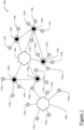
- Figure 1 shows a wireless network, for example a cellular network 100 , according to an embodiment of the present invention.
- the "Internet of Things” devices broadly encompass physical devices (usually referred to as “connected devices” or “smart devices” or “network devices”) embedded with electronics, software, and network connectivity that enable them to collect and exchange data).
- the network devices 110 i also feature sensing/metering capabilities, therefore in the following they will be referred to as sensor devices 110 i .
- the network node 105 k is a LTE/LTE-Advanced eNodeB, although this should not be construed limitatively.
- the network node 105 k is advantageously connected to other network nodes, such as to core network nodes (not shown).
- the sensor devices 110 i comprise sensor devices (for example, the sensor devices 110 1 , 110 4 , 110 9 , 110 14 and 110 18 ) connected to a power supply or having (e.g., due to better radio conditions experienced) a high or relatively high battery charge (hereinafter referred to as higher-energy sensor devices), and sensor devices (for example, the sensor devices 110 2 , 110 3 , 110 5 -110 8 , 110 10 -110 13 , 110 15 -110 17 , 110 19 -110 21 and 110 22 -110 26 ) not connected to a power supply or having low battery charge (hereinafter referred to as lower-energy sensor devices).
- sensor devices for example, the sensor devices 110 1 , 110 4 , 110 9 , 110 14 and 110 18
- higher-energy sensor devices for example, the sensor devices 110 2 , 110 3 , 110 5 -110 8 , 110 10 -110 13 , 110 15 -110 17 , 110 19 -110 21 and 110 22 -110 26
- lower-energy sensor devices for
- each sensor device 110 i (or at least one thereof) is capable of transmitting data to the serving network node 105 k over a direct radio communication link (hereinafter referred to as direct link) and to a different sensor device 110 i over a radio communication link referred to as relay link.
- direct link a direct radio communication link
- relay link a radio communication link
- five sensor device networks are assumed to be associated with the network node 105 1 , namely: a sensor device network DN A comprising the higher-energy sensor device 110 1 and the lower-energy sensor devices 110 2 and 110 3 , a sensor device network DN B comprising the higher-energy sensor device 110 4 and the lower-energy sensor devices 110 5 -110 8 , a sensor device network DNc comprising the higher-energy sensor device 110 9 and the lower-energy sensor devices 110 10 -110 13 , a sensor device network DN D comprising the higher-energy sensor device 110 14 and the lower-energy sensor devices 110 15 -110 17 , and a sensor device network DN E comprising the higher-energy sensor device 110 18 and the lower-energy sensor devices 110 19 -110 21 .
- one or more of the sensor device networks DN x may comprise one or more additional sensor devices capable of transmitting data only to the respective serving network nodes over the direct links - these additional sensor devices being not shown in the figure as they are not relevant for the understanding of the present invention.
- the network node 105 k (preferably a unit thereof, hereinafter IoT (" Internet of Things ”) unit) - or, in alternative embodiments of the present invention, one or more entities of the cellular network 100 external to the network nodes 105 k - is configured to carry out a method or procedure (hereinafter, IoT (" Internet of Things ") procedure) for configuring the cellular network 100 , and particularly for configuring one or more sensor devices 110 i (advantageously, one or more higher-energy sensor devices 110 i ) to perform data relaying on behalf of one or more other sensor devices 110 i (advantageously, one or more lower-energy sensor devices 110 i ) according to a radio quality of the respective direct and relay links.
- IoT Internet of Things
- each sensor device 110 i selected to perform data relaying (on behalf of one or more other sensor devices 110 i ) will be referred to as network additional node, whereas each sensor device 110 i supported with data relaying ( i.e. , each sensor device 110 i receiving or taking advantage of data relaying - or, otherwise stated, each sensor 110 i on behalf of which data relaying is carried out) will be referred to as supported sensor device 110 i .
- the radio quality of the direct links between each sensor device 110 i and the associated network node 105 k allows distinguishing sensor devices experiencing better radio conditions from sensor devices experiencing worse radio conditions (so that only the sensor devices experiencing better radio conditions are taken into consideration for performing data relaying, and only the sensor devices experiencing worse radio conditions are taken into consideration for being supported with data relaying).
- sensor device 110 i experiencing better radio conditions it is meant a sensor device 110 i having to perform a low, or relatively low, number of radio transmission attempts (for example, a number of radio transmissions attempts lower than a statically or dynamically predetermined first number of radio transmissions) to achieve connection (e.g., successful transmission of data) to the network node 105 k (such as a sensor device 110 i located in places with low (or relatively low) signal attenuation (e.g., outdoors)), and by sensor device 110 i experiencing worse radio conditions it is meant a sensor device 110 i having to perform a high, or relatively high, number of radio transmissions (for example, a number of radio transmissions higher than a statically or dynamically predetermined second number of radio transmission attempts, preferably equal to or higher than the first number of radio transmissions attempts) to achieve connection (e.g., successful transmission of data) to the network node 105 k (such as a sensor device 110 i located in places with high (or relatively high) signal atten
- data relaying it is meant a rebroadcasting of the received data to extend the broadcast reach.
- a first sensor device 110 i carrying out data relaying on behalf of a second sensor device 110 i interconnects the second sensor device 110 i to the serving network node 105 k by receiving data from the second sensor device 110 i over the relay link (between the first and second sensor devices 110 i ) and by rebroadcasting the received data to the serving network node 105 k over the direct link (between the first sensor device 110 i and the serving network node 105 k ) .
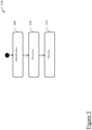
- an IoT procedure 200 is schematically shown in terms of functional modules. It is pointed out that the use of the term "module” is herein intended to emphasize functional (rather than implementation) aspects thereof. Indeed, without losing of generality, each module may be implemented by software (in which case, the resulting IoT procedure 200 would be performed by proper code means included in a computer program, when the program is run on a computer), hardware, and/or a combination thereof. Moreover, the modules may also reflect, at least conceptually, the physical structure of the network node 105 k (or of its IoT unit).
- the modules may have, by the physical viewpoint, distributed nature, it being understood that, by the logical viewpoint, they are all part of that IoT unit, wherever (and in whichever way) their physical implementation actually takes place.
- an IoT unit physically residing in each network node 105 k is provided.
- the IoT procedure 200 comprises three phases, broadly summarized herebelow and better discussed in the following:
- the sensor device information comprises information about conditions and functionalities of each sensor device 110 i .
- each sensor device 110 i transmits the sensor device information to the associated network node 105 k during its first connection to it - in any case, as will be better appreciated from the following discussion of exemplary sensor device information, some sensor device information is advantageously updated during sensor device 110 i life.
- the sensor device information comprises at least one (preferably, all) among:
- the IoT device information of a sensor device 110 i may comprise (additionally or alternatively to the above sensor device information) security information about that sensor device 110 i (e.g. , a sensor device 110 i may be involved in carrying sensible data), and the policy of forcing that sensor device 110 i to be directly connected to the associated network node 105 k without data relaying, and independently of the other sensor device information, could be contemplated.
- the acquisition phase of sensor device information comprises sending, by the network node 105 k , a request message to the associated sensor devices 110 i ( e.g., on the PBCH or the PDCCH channels), in rensponse to which the sensor device information is transmitted by the sensor devices 110 i to the associated network node 105 k ( e.g., on the PUCCH or the PRACH channels).
- the recognition phase 210 comprises at least one among (preferably, all) the steps discussed herebelow.
- sensor devices 110 i associated with different network nodes 105 k can be handled by a single candidate network additional node. This could be the case of, for example, a candidate network additional node that discovers in its proximity ( i.e., it receives the transmission attempts from) a sensor device 110 i that is under the coverage of a network node 105 k different from the serving network node for that candidate network additional node - hereinafter referred to as non-serving network node.
- the network node 105 2 acts as serving network node for the sensor device 110 17 and the network node 105 1 acts as serving network node for the sensor device 110 14
- a candidate network additional node may discover in its proximity a sensor device 110 i (hereinafter external sensor device) that is under the coverage of a network node 105 k different from the serving network node ( i.e., non-serving network node) for that candidate network additional node when, for example, the two network nodes are coordinated and are able to configure the same radio resources for the P-PRACH or for the S-PRACH channels.
- the candidate network additional node may receive the relay link radio quality from the external sensor device on the P-PRACH channel (autonomous discovery step) or on the S-PRACH channel (assisted discovery step).
- the relay link radio quality may be reported by the candidate network additional node to its own serving network node (i.e., the network node that is serving the candidate network additional node), which in turn may route to the correct network node 105 k the reported relay link radio quality.
- Election step 315 the (or each) candidate network additional node and the related supported sensor device are elected (preferably, by the network node 105 k ) as network additional node and supported sensor device, respectively, according to the radio quality of the respective direct and relay links.
- each candidate network additional node and a related candidate supported sensor device are elected as network additional node and supported sensor device, respectively, based on a comparison between the associated relay link and direct link radio quality.
- each candidate network additional node and a related candidate supported sensor device are elected as network additional node and supported sensor device, respectively, if said comparison results in a quality of the relay link between that candidate supported sensor device and that candidate network additional node higher than the quality of the direct link between that candidate supported sensor device and the network node 105 k .
- the election of the (or each) candidate network additional node and the related candidate supported sensor device(s) as network additional node and supported sensor device(s), respectively takes place by means of a cell reselection message sent from the network node 105 k to each network additional node and supported sensor device so as to inform them of their election for data relaying.
- one or more higher-energy sensor devices experiencing better radio conditions are selected to relay the data of respective one or more lower-energy sensor devices experiencing worse radio conditions to the associated network node 105 k - as opposed to conventional cellular networks including sensor devices, wherein the lower-energy sensor devices experiencing worse radio conditions are instead connected directly only to the associated network node.
- Figure 4 is a simplified swim-lane representation of the recognition phase 210 , and particularly of the autonomous and assisted discovery steps, according to an embodiment of the present invention.
- the recognition phase is advantageously intended to be carried out at each network node 105 k and involve all the sensor devices 110 i associated therewith (as well as those in proximity thereto, as discussed above in connection with the case of sensor devices 110 i associated with different network nodes 105 k but handled by a single candidate network additional node).
- the sensor device 110 1 is assumed to be the candidate network additional node and the sensor devices 110 2 and 110 3 are assumed to be the candidate supported sensor devices (in any case, as mentioned above, according to specific policies, the relevance of one or more sensor device information may also involve that one or more sensor devices 110 i of a sensor device network DN x are regarded neither as candidate network additional nodes nor as candidate supported sensor devices).
- the sensor devices 110 1 and 110 3 are assumed to support data transmission on both P-PRACH and S-PRACH channels, whereas the sensor device 110 2 is assumed to support data transmission only on the P-PRACH channel (reason why the network node 105 1 and the candidate network additional node 110 1 are assumed to carry out the autonomous discovery step for the candidate supported node 110 2 and the assisted discovery step for the candidate supported node 110 3 ) .
- the autonomous discovery step of the example of Figure 4 can be summarized as follows.
- the network node 105 1 receives, on the P-PRACH channel, the transmission attempts of the candidate supported sensor device 110 2 (step 310a 1 ) together with the direct link radio quality relating to the direct link between the network node 105 1 and the candidate supported sensor device 110 2 (denoted by " QD2 " in the figure).
- the candidate network additional node 110 1 intercepts ( i.e., receives) these transmission attempts (step 310a 2 ) and determines the relay link radio quality (relating to the relay link between the candidate supported sensor device 110 2 and the candidate network additional node 110 1 ) according to the quality of the intercepted transmission attempts.
- the candidate network additional node 110 1 reports (step 310a 3 ) to the network node 105 1 the relay link radio quality (denoted by " QR2 " in the figure).
- the assisted discovery step of the example of Figure 4 can be summarized as follows.
- the network node 105 1 receives, preferably on the P-PRACH channel, a first transmission attempt (or a first set of transmission attempts) from the candidate supported sensor device 110 3 , together with the direct link radio quality relating to the direct link between the network node 105 1 and the candidate supported sensor device 110 3 (denoted by " QD3 " in the figure) - step 310b 1 .
- the network node 105 1 sends, preferably on the PDCCH channel, a feedback about said first transmission attempt (step 310b 2 ) .
- the network node 105 1 sends the feedback to the candidate supported sensor device 110 3 , said feedback preferably comprising configuration signalling for configuring the candidate supported sensor device 110 3 to transmit the subsequent transmission attempts (or a set of transmission attempts following the first transmission attempt or the first set of transmission attempts) to the candidate network additional node 110 1 (rather than to the network node 105 i ), and preferably on the S-PRACH channel - step 310b 3 .
- the network node 105 1 sends said feedback also to the candidate network additional node 110 1 , and even more preferably said feedback also comprises configuration signalling for configuring the candidate network additional node 110 1 to determine, according to the quality of the received subsequent transmission attempts, the relay link radio quality relating to the relay link between the candidate supported sensor device 110 3 and the candidate network additional node 110 1 .
- the candidate network additional node 110 1 reports to the network node 105 1 the relay link radio quality (denoted by " QR3 " in the figure) of the relay link between the candidate supported sensor device 110 3 and the candidate network additional node 110 1 - step 310b 4 .
- the candidate supported sensor device 110 3 may be configured ( e.g., by the network node 105 1 ) to transmit ( i.e., to keep on transmitting) the subsequent transmission attempts to the network node 105 1 on the P-PRACH channel, and the candidate network additional node 110 1 may be configured (e.g., by the network node 105 1 ) to intercept ( e .
- the candidate network additional node 110 1 reports to the network node 105 1 the relay link radio quality measurements.
- the configuration phase 215 comprises at least one among (preferably, all) the steps discussed herebelow:
- the connection is handled directly by the network additional node, which can schedule the supported sensor device in the radio resouces of the PUSCH/PDSCH channels reserved during the previous step and signalled using the resource assignment message, thereafter the received message from the supported sensor device is preferably relayed from the network additional node to the network node 105 k using the radio resources of the PUSCH channel normally scheduled by the network node 105 k .
- the decision between the direct link and the relay link for data transmission/reception i.e., the decision of whether the (candidate) network additional node having discovered the external sensor device may in turn act as additional network node also for that external sensor device
- the network node 105 k that receives the transmission attempts from the sensor device 110 i on the P-PRACH channel ( i.e., the non-serving network node 105 2 in the
- both non-serving and serving network nodes decide about the radio resources to reserve for the channels of the relay link (e.g., S-SS signals and S-PRACH channels), thereafter the serving network node sends a respective resource assignment message to the network additional node (so as to inform it will act as the network additional node for the external sensor device) and the non-serving network node sends a respective resource redirection message to the external sensor device (that is, external from the serving network node viewpoint) to inform it about the P-SS signals and P-RACH channels of the serving network node and about data relaying carried out by the associated network additional node on behalf of it (providing the external sensor device with the corresponding S-SS signals and S-PRACH channels).
- the serving network node sends a respective resource assignment message to the network additional node (so as to inform it will act as the network additional node for the external sensor device) and the non-serving network node sends a respective resource redirection message to the external sensor device (that is, external from the
- the present invention lends itself to be implemented through an equivalent method (by using similar steps, removing some steps being not essential, or adding further optional steps); moreover, the steps may be performed in different order, concurrently or in an interleaved way (at least partly).
- any component thereof may be separated into several elements, or two or more components may be combined into a single element; in addition, each component may be replicated for supporting the execution of the corresponding operations in parallel. It should also be noted that any interaction between different components generally does not need to be continuous (unless otherwise indicated), and it may be both direct and indirect through one or more intermediaries.
Landscapes
- Engineering & Computer Science (AREA)
- Computer Networks & Wireless Communication (AREA)
- Signal Processing (AREA)
- Mobile Radio Communication Systems (AREA)
Claims (14)
- Verfahren (200) zum Auslegen eines drahtlosen Netzwerks (100), wobei das drahtlose Netzwerk (100) einen Netzwerkknoten (105 k ) und eine erste Netzwerkvorrichtung (110 i ), die vom Netzwerkknoten (105 k ) abgedeckt wird, umfasst, wobei der Netzwerkknoten (105 k ) als bedienender Netzwerkknoten für die erste Netzwerkvorrichtung fungiert und wobei die erste Netzwerkvorrichtung zum Übertragen von ersten Daten über einen ersten Funklink zum Netzwerkknoten (105 k ) angeordnet ist, wobei das Verfahren Folgendes umfasst:Bestimmen des Vorhandenseins einer zweiten Netzwerkvorrichtung (110 i ), die vom Netzwerkknoten (105 k ) abgedeckt wird, wobei die zweite Netzwerkvorrichtung zum Übertragen von zweiten Daten über einen zweiten Funklink zu einem jeweiligen bedienenden Netzwerkknoten angeordnet ist,Bestimmen (210,310) einer Funkqualität des ersten Funklinks, Bestimmen (210,310) einer Funkqualität des zweiten Funklinks, Bestimmen (210,310) einer Funkqualität eines dritten Funklinks zwischen der zweiten Netzwerkvorrichtung und der ersten Netzwerkvorrichtung undfalls die Funkqualität des dritten Funklinks höher ist als die Funkqualität des zweiten Funklinks, Auslegen (215) der zweiten Netzwerkvorrichtung zum Übertragen der zweiten Daten über den dritten Funklink zur ersten Netzwerkvorrichtung und der ersten Netzwerkvorrichtung zum Neuübertragen der zweiten Daten über den ersten Funklink zum Netzwerkknoten, wobei das drahtlose Netzwerk (100) erste Synchronisationssignale und einen ersten physischen Direktzugriffskanal zum Aufbauen einer Direktverbindung zwischen der ersten Netzwerkvorrichtung und dem Netzwerkknoten (105 k ) und zwischen der zweiten Netzwerkvorrichtung und dem jeweiligen bedienenden Netzwerkknoten (105 k ) und zweite Synchronisationssignale und einen zweiten physischen Direktzugriffskanal zum Aufbauen einer Direktverbindung zwischen der ersten Netzwerkvorrichtung und der zweiten Netzwerkvorrichtung unterstützt und wobei das Auslegen (215) der zweiten Netzwerkvorrichtung zum Übertragen der zweiten Daten über den dritten Funklink zur ersten Netzwerkvorrichtung und der ersten Netzwerkvorrichtung zum Neuübertragen der zweiten Daten über den ersten Funklink zum Netzwerkknoten durchgeführt wird, wenn die erste Netzwerkvorrichtung mindestens die Übertragung der zweiten Synchronisationssignale und den Empfang auf dem zweiten physischen Direktzugriffskanal unterstützt und die zweite Netzwerkvorrichtung mindestens die Übertragung auf dem ersten physischen Direktzugriffskanal und auf dem zweiten physischen Direktzugriffskanal und den Empfang der zweiten Synchronisationssignale unterstützt.
- Verfahren (200) nach Anspruch 1, wobei das Bestimmen (210,310) einer Funkqualität eines dritten Funklinks Folgendes umfasst:Bewirken (310a1 ) , dass die zweite Netzwerkvorrichtung Anforderungen von Funkressourcen und der Funkqualität des zweiten Funklinks zum Netzwerkknoten (105 k ) auf dem ersten Direktzugriffskanal überträgt,Bewirken (310a2) , dass die erste Netzwerkvorrichtung die Anforderungen von Funkressourcen und der Funkqualität des zweiten Funklinks abfängt, undBewirken (310a3 ), dass die erste Netzwerkvorrichtung die Funkqualität des dritten Funklinks auf Basis der Qualität der abgefangenen Anforderungen von Funkressourcen und der abgefangenen Funkqualität des zweiten Funklinks bestimmt.
- Verfahren (200) nach Anspruch 1, wobei das Bestimmen (210,310) einer Funkqualität eines dritten Funklinks Folgendes umfasst:Bewirken (310b1 ), dass die zweite Netzwerkvorrichtung einen ersten Satz von Anforderungen von Funkressourcen und der Funkqualität des zweiten Funklinks auf dem ersten Direktzugriffskanal zum Netzwerkknoten (105 k ) überträgt, undbei Vorhandensein einer Rückmeldung des Netzwerkknotens (105 k ) über den übertragenen ersten Satz von Anforderungen von Funkressourcen an der zweiten Netzwerkvorrichtung:Bewirken (310b3 ), dass die zweite Netzwerkvorrichtung nach dem ersten Satz von Anforderungen von Funkressourcen nachfolgende Anforderungen von Funkressourcen auf dem zweiten physischen Direktzugriffskanal zur ersten Netzwerkvorrichtung überträgt, undBewirken (310b4 ), dass die erste Netzwerkvorrichtung die Funkqualität des dritten Funklinks auf Basis einer Qualität der empfangenen nachfolgenden Anforderungen von Funkressourcen bestimmt.
- Verfahren (200) nach Anspruch 1, wobei das Bestimmen (210,310) einer Funkqualität eines dritten Funklinks Folgendes umfasst:Bewirken (310b1 ), dass die zweite Netzwerkvorrichtung einen ersten Satz von Anforderungen von Funkressourcen und der Funkqualität des zweiten Funklinks auf dem ersten Direktzugriffskanal zum Netzwerkknoten (105k ) überträgt, undbei Fehlen einer Rückmeldung des Netzwerkknotens (105k ) über den ersten Satz von Anforderungen von Funkressourcen an der zweiten Netzwerkvorrichtung:Bewirken, dass die zweite Netzwerkvorrichtung nach dem ersten Satz von Anforderungen von Funkressourcen nachfolgende Anforderungen von Funkressourcen auf dem ersten physischen Direktzugriffskanal zum Netzwerkknoten (105 k ) überträgt, Bewirken, dass die erste Netzwerkvorrichtung die nachfolgenden Anforderungen von Funkressourcen abfängt, undBestimmen der Funkqualität des dritten Funklinks auf Basis der Qualität der abgefangenen nachfolgenden Anforderungen von Funkressourcen.
- Verfahren (200) nach einem der Ansprüche 2 bis 4, wobei das Bestimmen der Funkqualität des dritten Funklinks auch auf einer Beurteilung der zweiten Synchronisationssignale, die von der ersten Netzwerkvorrichtung zur zweiten Netzwerkvorrichtung übertragen werden, basiert.
- Verfahren (200) nach einem der vorhergehenden Ansprüche, wobei der Netzwerkknoten (105 k ) auch für die zweite Netzwerkvorrichtung als ein bedienender Netzwerkknoten fungiert und wobei das Auslegen (215) der zweiten Netzwerkvorrichtung zum Übertragen der zweiten Daten über den dritten Funklink zur ersten Netzwerkvorrichtung und der ersten Netzwerkvorrichtung zum Neuübertragen der zweiten Daten über den ersten Funklink zum Netzwerkknoten ferner Folgendes umfasst:Bewirken, dass der Netzwerkknoten (105 k ) eine erste Ressourcenzuweisungsnachricht an die erste Netzwerkvorrichtung und eine zweite Ressourcenzuweisungsnachricht an die zweite Netzwerkvorrichtung sendet;Bewirken, dass die erste Netzwerkvorrichtung die zweiten Synchronisationssignale periodisch überträgt, undBewirken, dass sich die zweite Netzwerkvorrichtung gemäß den empfangenen zweiten Synchronisationssignalen mit der ersten Netzwerkvorrichtung synchronisiert.
- Verfahren (200) nach Anspruch 6, wobei die zweite Ressourcenzuweisungsnachricht auch die Informationen über reservierte Funkressourcen, die für eine Downlink- und Uplinkdatenübertragung auf dem dritten Funklink reserviert sind, enthält.
- Verfahren (200) nach einem der Ansprüche 1 bis 5, wobei das drahtlose Netzwerk einen weiteren Netzwerkknoten umfasst, wobei der weitere Netzwerkknoten als ein bedienender Netzwerkknoten für die zweite Netzwerkvorrichtung fungiert und wobei das Verfahren ferner das Bewirken, dass der Netzwerkknoten den weiteren Netzwerkknoten über die Verfügbarkeit der ersten Netzwerkvorrichtung informiert, zu der die zweite Netzwerkvorrichtung die zweiten Daten über den dritten Funklink übertragen kann, umfasst.
- Verfahren nach Anspruch 8, wobei das Auslegen (215) der zweiten Netzwerkvorrichtung zum Übertragen der zweiten Daten über den dritten Funklink zur ersten Netzwerkvorrichtung und der ersten Netzwerkvorrichtung zum Neuübertragen der zweiten Daten über den ersten Funklink zum Netzwerkknoten ferner Folgendes umfasst:Bewirken, dass der Netzwerkknoten (105 k ) eine Ressourcenzuweisungsnachricht an die erste Netzwerkvorrichtung sendet,Bewirken, dass der weitere Netzwerkknoten eine Ressourcenumleitungsnachricht an die zweite Netzwerkvorrichtung sendet;Bewirken, dass die erste Netzwerkvorrichtung die zweiten Synchronisationssignale periodisch überträgt, undBewirken, dass sich die zweite Netzwerkvorrichtung gemäß den empfangenen zweiten Synchronisationssignalen mit der ersten Netzwerkvorrichtung synchronisiert.
- Verfahren (200) nach einem der Ansprüche 2 bis 9, wobei die Funkqualität des ersten Funklinks auf den ersten Synchronisationssignalen vom Netzwerkknoten (105 k ) zur ersten Netzwerkvorrichtung basiert und wobei die Funkqualität des zweiten Funklinks auf den ersten Synchronisationssignalen vom jeweiligen bedienenden Netzwerkknoten (105 k ) zur zweiten Netzwerkvorrichtung basiert.
- Verfahren (200) nach einem der vorhergehenden Ansprüche, das ferner das Bestimmen (205) einer Energieverfügbarkeit der ersten Netzwerkvorrichtung und einer Energieverfügbarkeit der zweiten Netzwerkvorrichtung umfasst, wobei das Auslegen (215) der zweiten Netzwerkvorrichtung zum Übertragen der zweiten Daten über den dritten Funklink zur ersten Netzwerkvorrichtung und der ersten Netzwerkvorrichtung zum Neuübertragen der zweiten Daten über den ersten Funklink zum Netzwerkknoten durchgeführt wird, wenn die Energieverfügbarkeit der ersten Netzwerkvorrichtung größer ist als die Energieverfügbarkeit der zweiten Netzwerkvorrichtung.
- Verfahren (200) nach einem der vorhergehenden Ansprüche, wobei das Auslegen (215) der zweiten Netzwerkvorrichtung zum Übertragen der zweiten Daten über den dritten Funklink zur ersten Netzwerkvorrichtung und der ersten Netzwerkvorrichtung zum Neuübertragen der zweiten Daten über den ersten Funklink zum Netzwerkknoten auch auf Basis von mindestens einem von Folgendem umgesetzt wird:einer Anzeige eines Vorrichtungsnetzwerks, zu dem die erste und die zweite Netzwerkvorrichtung gehören;einer Anzeige einer maximalen Sendeleistung, die von der ersten und der zweiten Netzwerkvorrichtung unterstützt wird;einer Anzeige über vordefinierte Übertragungszeitperioden der ersten und der zweiten Netzwerkvorrichtung undeiner Anzeige der Position und Mobilität der ersten und der zweiten Netzwerkvorrichtung.
- Netzwerkknoten (105 k ) zur Verwendung in einem drahtlosen Netzwerk (100), wobei das drahtlose Netzwerk (100) den Netzwerkknoten (105 k ) und eine erste Netzwerkvorrichtung (110 i ), die vom Netzwerkknoten (105 k ) abgedeckt wird, umfasst, wobei der Netzwerkknoten (105 k ) als bedienender Netzwerkknoten für die erste Netzwerkvorrichtung fungiert und wobei die erste Netzwerkvorrichtung zum Übertragen von ersten Daten über einen ersten Funklink zum Netzwerkknoten (105 k ) angeordnet ist, wobei der Netzwerkknoten zu Folgendem angeordnet ist:Bestimmen des Vorhandenseins einer zweiten Netzwerkvorrichtung (110 i ), die vom Netzwerkknoten (105 k ) abgedeckt wird, wobei die zweite Netzwerkvorrichtung zum Übertragen von zweiten Daten über einen zweiten Funklink zu einem jeweiligen bedienenden Netzwerkknoten angeordnet ist,Bestimmen (210,310) einer Funkqualität des ersten Funklinks, Bestimmen (210,310) einer Funkqualität des zweiten Funklinks, Bestimmen (210,310) einer Funkqualität eines dritten Funklinks zwischen der zweiten Netzwerkvorrichtung und der ersten Netzwerkvorrichtung undwenn die Funkqualität des dritten Funklinks höher ist als die Funkqualität des zweiten Funklinks, Auslegen (215) der zweiten Netzwerkvorrichtung zum Übertragen der zweiten Daten über den dritten Funklink zur ersten Netzwerkvorrichtung und der ersten Netzwerkvorrichtung zum Neuübertragen der zweiten Daten über den ersten Funklink zum Netzwerkknoten.wobei das drahtlose Netzwerk (100) erste Synchronisationssignale und einen ersten physischen Direktzugriffskanal zum Aufbauen einer Direktverbindung zwischen der ersten Netzwerkvorrichtung und dem Netzwerkknoten (105 k ) und zwischen der zweiten Netzwerkvorrichtung und dem jeweiligen bedienenden Netzwerkknoten (105 k ) und zweite Synchronisationssignale und einen zweiten physischen Direktzugriffskanal zum Aufbauen einer Direktverbindung zwischen der ersten Netzwerkvorrichtung und der zweiten Netzwerkvorrichtung unterstützt und wobei der Netzwerkknoten zum Auslegen (215) der zweiten Netzwerkvorrichtung zum Übertragen der zweiten Daten über den dritten Funklink zur ersten Netzwerkvorrichtung und der ersten Netzwerkvorrichtung zum Neuübertragen der zweiten Daten über den ersten Funklink zum Netzwerkknoten angeordnet ist, wenn die erste Netzwerkvorrichtung mindestens die Übertragung der zweiten Synchronisationssignale und den Empfang auf dem zweiten physischen Direktzugriffskanal unterstützt und die zweite Netzwerkvorrichtung mindestens die Übertragung auf dem ersten physischen Direktzugriffskanal und auf dem zweiten physischen Direktzugriffskanal und den Empfang der zweiten Synchronisationssignale unterstützt.
- Vorrichtungsnetzwerk zur Verwendung in einem drahtlosen Netzwerk (100), wobei das Vorrichtungsnetzwerk eine erste Netzwerkvorrichtung, die zum Übertragen von ersten Daten über einen ersten Funklink zu einem Netzwerkknoten angeordnet ist, und eine zweite Netzwerkvorrichtung (110 i ), die zum Übertragen von zweiten Daten über einen zweiten Funklink zum Netzwerkknoten angeordnet ist, umfasst, wobei, wenn die erste und die zweite Netzwerkvorrichtung vom Netzwerkknoten (105 k ) des Mobilfunknetzwerks abgedeckt werden und wenn der Netzwerkknoten (105 k ) als ein bedienender Netzwerkknoten für die erste Netzwerkvorrichtung fungiert:wenn die Funkqualität eines dritten Funklinks, der ein Link zwischen der ersten und der zweiten Netzwerkvorrichtung ist, höher ist als die Funkqualität des zweiten Funklinks, die zweite Netzwerkvorrichtung zum Übertragen der zweiten Daten über den dritten Funklink zur ersten Netzwerkvorrichtung angeordnet ist und die erste Netzwerkvorrichtung zum Neuübertragen der zweiten Daten über den ersten Funklink zum Netzwerkknoten angeordnet ist,wobei das drahtlose Netzwerk (100) erste Synchronisationssignale und einen ersten physischen Direktzugriffskanal zum Aufbauen einer Direktverbindung zwischen der ersten Netzwerkvorrichtung und dem Netzwerkknoten (105 k ) und zwischen der zweiten Netzwerkvorrichtung und dem jeweiligen bedienenden Netzwerkknoten (105 k ) und zweite Synchronisationssignale und einen zweiten physischen Direktzugriffskanal zum Aufbauen einer Direktverbindung zwischen der ersten Netzwerkvorrichtung und der zweiten Netzwerkvorrichtung unterstützt und wobei die zweite Netzwerkvorrichtung zum Übertragen der zweiten Daten über den dritten Funklink zur ersten Netzwerkvorrichtung angeordnet ist und die erste Netzwerkvorrichtung zum Neuübertragen der zweiten Daten über den ersten Funklink zum Netzwerkknoten angeordnet ist, wenn die erste Netzwerkvorrichtung mindestens die Übertragung der zweiten Synchronisationssignale und den Empfang auf dem zweiten physischen Direktzugriffskanal unterstützt und die zweite Netzwerkvorrichtung mindestens die Übertragung auf dem ersten physischen Direktzugriffskanal und auf dem zweiten physischen Direktzugriffskanal und den Empfang der zweiten Synchronisationssignale unterstützt.
Priority Applications (1)
| Application Number | Priority Date | Filing Date | Title |
|---|---|---|---|
| EP21214048.7A EP3998837B1 (de) | 2017-03-30 | 2018-03-13 | Konfigurierbares netzwerk für eine drahtlose vorrichtung |
Applications Claiming Priority (2)
| Application Number | Priority Date | Filing Date | Title |
|---|---|---|---|
| IT102017000035262A IT201700035262A1 (it) | 2017-03-30 | 2017-03-30 | Rete di dispositivi senza fili configurabile |
| PCT/EP2018/056242 WO2018177740A1 (en) | 2017-03-30 | 2018-03-13 | Configurable wireless device network |
Related Child Applications (2)
| Application Number | Title | Priority Date | Filing Date |
|---|---|---|---|
| EP21214048.7A Division EP3998837B1 (de) | 2017-03-30 | 2018-03-13 | Konfigurierbares netzwerk für eine drahtlose vorrichtung |
| EP21214048.7A Division-Into EP3998837B1 (de) | 2017-03-30 | 2018-03-13 | Konfigurierbares netzwerk für eine drahtlose vorrichtung |
Publications (2)
| Publication Number | Publication Date |
|---|---|
| EP3603328A1 EP3603328A1 (de) | 2020-02-05 |
| EP3603328B1 true EP3603328B1 (de) | 2022-01-19 |
Family
ID=59521572
Family Applications (2)
| Application Number | Title | Priority Date | Filing Date |
|---|---|---|---|
| EP18714449.8A Active EP3603328B1 (de) | 2017-03-30 | 2018-03-13 | Konfigurierbares netzwerk für eine drathlose vorrichtung |
| EP21214048.7A Active EP3998837B1 (de) | 2017-03-30 | 2018-03-13 | Konfigurierbares netzwerk für eine drahtlose vorrichtung |
Family Applications After (1)
| Application Number | Title | Priority Date | Filing Date |
|---|---|---|---|
| EP21214048.7A Active EP3998837B1 (de) | 2017-03-30 | 2018-03-13 | Konfigurierbares netzwerk für eine drahtlose vorrichtung |
Country Status (7)
| Country | Link |
|---|---|
| US (2) | US11212872B2 (de) |
| EP (2) | EP3603328B1 (de) |
| KR (1) | KR102576228B1 (de) |
| CN (1) | CN110583096B (de) |
| ES (2) | ES3047835T3 (de) |
| IT (1) | IT201700035262A1 (de) |
| WO (1) | WO2018177740A1 (de) |
Families Citing this family (2)
| Publication number | Priority date | Publication date | Assignee | Title |
|---|---|---|---|---|
| CN111615170B (zh) * | 2020-05-18 | 2021-03-12 | 北京世纪鼎点软件有限公司 | 一种数据传输方法及系统 |
| WO2025166719A1 (zh) * | 2024-02-08 | 2025-08-14 | Oppo广东移动通信有限公司 | 通信方法、装置、设备及存储介质 |
Family Cites Families (19)
| Publication number | Priority date | Publication date | Assignee | Title |
|---|---|---|---|---|
| US8942082B2 (en) * | 2002-05-14 | 2015-01-27 | Genghiscomm Holdings, LLC | Cooperative subspace multiplexing in content delivery networks |
| US9113496B2 (en) | 2010-04-25 | 2015-08-18 | Lg Electronics Inc. | Method and apparatus for transceiving data in a wireless access system |
| US20120033613A1 (en) * | 2010-08-04 | 2012-02-09 | National Taiwan University | Enhanced rach design for machine-type communications |
| EP2620028B1 (de) * | 2010-09-23 | 2020-04-29 | BlackBerry Limited | System und verfahren für dynamische koordination der funkressourcennutzung in einer drahtlosnetzwerkumgebung |
| JP2013051540A (ja) * | 2011-08-31 | 2013-03-14 | Sharp Corp | 無線中継通信システム、無線通信システム、移動局装置データベース、基地局装置、無線局装置、集積回路、コンピュータプログラムおよび記録媒体 |
| WO2014050886A1 (ja) | 2012-09-27 | 2014-04-03 | 京セラ株式会社 | 移動通信システム |
| WO2015014395A1 (en) * | 2013-07-31 | 2015-02-05 | Telecom Italia S.P.A. | Device-to-device communication management in mobile communication networks |
| US9319127B2 (en) * | 2013-08-09 | 2016-04-19 | Electronics And Telecommunications Research Institute | Method of relay between devices |
| US9629191B2 (en) * | 2013-11-12 | 2017-04-18 | Blackberry Limited | Systems and methods for initiating device-to-device communication in wireless networks |
| EP3100559B1 (de) * | 2014-01-27 | 2020-09-16 | Telefonaktiebolaget LM Ericsson (publ) | Netzwerkknoten, drahtlose vorrichtung, verfahren darin, computerprogramme und computerlesbare medien mit den computerprogrammen zur anpassung und übernahme einer zuweisung von funkressourcen |
| CN110855416A (zh) * | 2014-04-30 | 2020-02-28 | Oppo广东移动通信有限公司 | 设备到设备通信的方法、用户设备、网络节点及存储介质 |
| JP6407304B2 (ja) * | 2014-05-08 | 2018-10-17 | シャープ株式会社 | デバイス・ツー・デバイス通信装置および方法 |
| KR102247142B1 (ko) * | 2014-05-09 | 2021-05-04 | 삼성전자주식회사 | 단말 간 통신을 위한 동기 신호 전송 방법 및 장치 |
| EP3243360B1 (de) * | 2015-02-11 | 2021-12-29 | Sony Group Corporation | Kommunikationseinrichtungen , infrastrukturausrüstungen und verfahren zur auswahl eines relays in geräte-zu-geratekommunikation |
| WO2016179832A1 (zh) * | 2015-05-14 | 2016-11-17 | 富士通株式会社 | 中继选择或重选方法、装置和系统 |
| CN106304173B (zh) * | 2015-05-25 | 2020-01-24 | 上海诺基亚贝尔股份有限公司 | 在d2d用户设备中用于测量无线链路质量的方法 |
| ES2897648T3 (es) * | 2015-08-19 | 2022-03-02 | Nokia Technologies Oy | Control de uso de UE retransmisor |
| EP3338492A4 (de) * | 2015-08-21 | 2019-03-20 | Nokia Technologies Oy | Vorrichtung, verfahren und computerprogrammprodukt für medienzugriffssteuerung in einem drahtlosen sensornetzwerk |
| KR101954495B1 (ko) * | 2015-09-23 | 2019-03-07 | 주식회사 케이티 | 단말의 이동성 제어 방법 및 그 장치 |
-
2017
- 2017-03-30 IT IT102017000035262A patent/IT201700035262A1/it unknown
-
2018
- 2018-03-13 KR KR1020197031816A patent/KR102576228B1/ko active Active
- 2018-03-13 US US16/495,915 patent/US11212872B2/en active Active
- 2018-03-13 ES ES21214048T patent/ES3047835T3/es active Active
- 2018-03-13 ES ES18714449T patent/ES2911615T3/es active Active
- 2018-03-13 CN CN201880029056.6A patent/CN110583096B/zh active Active
- 2018-03-13 EP EP18714449.8A patent/EP3603328B1/de active Active
- 2018-03-13 EP EP21214048.7A patent/EP3998837B1/de active Active
- 2018-03-13 WO PCT/EP2018/056242 patent/WO2018177740A1/en not_active Ceased
-
2021
- 2021-12-01 US US17/539,241 patent/US11647562B2/en active Active
Also Published As
| Publication number | Publication date |
|---|---|
| EP3603328A1 (de) | 2020-02-05 |
| CN110583096A (zh) | 2019-12-17 |
| KR20190133226A (ko) | 2019-12-02 |
| US11212872B2 (en) | 2021-12-28 |
| US20200137832A1 (en) | 2020-04-30 |
| ES2911615T3 (es) | 2022-05-20 |
| IT201700035262A1 (it) | 2018-09-30 |
| US20220095418A1 (en) | 2022-03-24 |
| US11647562B2 (en) | 2023-05-09 |
| CN110583096B (zh) | 2022-10-11 |
| EP3998837A1 (de) | 2022-05-18 |
| WO2018177740A1 (en) | 2018-10-04 |
| EP3998837B1 (de) | 2025-08-20 |
| KR102576228B1 (ko) | 2023-09-07 |
| ES3047835T3 (en) | 2025-12-05 |
Similar Documents
| Publication | Publication Date | Title |
|---|---|---|
| US11985726B2 (en) | Channel state information (CSI) reporting during a discontinuous reception (DRX) cycle | |
| EP2984890B1 (de) | Auswahl einer uplink-downlink-konfiguration für cluster aus zellen | |
| WO2021232176A1 (en) | Discontinuous reception for sidelink communications in wireless communications systems | |
| CN110999410B (zh) | 在非自立配置中经由跨rat信令进行功率管理的技术和装置 | |
| US20240236951A1 (en) | Gradual sensing for user equipment power saving in sidelink operation | |
| EP4133821B1 (de) | Tracking reference signal (trs) für benutzergeräte im idle mode | |
| US20220394671A1 (en) | Systems and Methods for UE-specific Notifications with Beamforming | |
| US20240188042A1 (en) | Paging early indication enhancements | |
| WO2019028825A1 (en) | TECHNIQUES AND APPARATUSES USED FOR ALARM SIGNALING IN A MULTI-BEAM SYSTEM | |
| US11647562B2 (en) | Configurable wireless device network | |
| WO2019005283A1 (en) | TECHNIQUES AND APPARATUS FOR DISCOVERY OF COMMUNICATION RELAY | |
| US11871215B2 (en) | Uplink-centric handover in a wireless multi-hop network | |
| WO2021097596A1 (en) | Wake up signal pool for waking up multiple user equipments | |
| WO2023209210A1 (en) | Technique for variable network capacity use | |
| KR20240148741A (ko) | 통신 네트워크에서 nes 기능의 지원 방법 및 장치 | |
| WO2021217399A1 (en) | Recovery from repeated network configuration failure | |
| CN120548778A (zh) | 侧链端到端服务质量拆分报告 |
Legal Events
| Date | Code | Title | Description |
|---|---|---|---|
| STAA | Information on the status of an ep patent application or granted ep patent |
Free format text: STATUS: UNKNOWN |
|
| STAA | Information on the status of an ep patent application or granted ep patent |
Free format text: STATUS: THE INTERNATIONAL PUBLICATION HAS BEEN MADE |
|
| PUAI | Public reference made under article 153(3) epc to a published international application that has entered the european phase |
Free format text: ORIGINAL CODE: 0009012 |
|
| STAA | Information on the status of an ep patent application or granted ep patent |
Free format text: STATUS: REQUEST FOR EXAMINATION WAS MADE |
|
| 17P | Request for examination filed |
Effective date: 20191022 |
|
| AK | Designated contracting states |
Kind code of ref document: A1 Designated state(s): AL AT BE BG CH CY CZ DE DK EE ES FI FR GB GR HR HU IE IS IT LI LT LU LV MC MK MT NL NO PL PT RO RS SE SI SK SM TR |
|
| AX | Request for extension of the european patent |
Extension state: BA ME |
|
| DAV | Request for validation of the european patent (deleted) | ||
| DAX | Request for extension of the european patent (deleted) | ||
| GRAP | Despatch of communication of intention to grant a patent |
Free format text: ORIGINAL CODE: EPIDOSNIGR1 |
|
| STAA | Information on the status of an ep patent application or granted ep patent |
Free format text: STATUS: GRANT OF PATENT IS INTENDED |
|
| INTG | Intention to grant announced |
Effective date: 20210914 |
|
| GRAS | Grant fee paid |
Free format text: ORIGINAL CODE: EPIDOSNIGR3 |
|
| GRAA | (expected) grant |
Free format text: ORIGINAL CODE: 0009210 |
|
| STAA | Information on the status of an ep patent application or granted ep patent |
Free format text: STATUS: THE PATENT HAS BEEN GRANTED |
|
| AK | Designated contracting states |
Kind code of ref document: B1 Designated state(s): AL AT BE BG CH CY CZ DE DK EE ES FI FR GB GR HR HU IE IS IT LI LT LU LV MC MK MT NL NO PL PT RO RS SE SI SK SM TR |
|
| REG | Reference to a national code |
Ref country code: GB Ref legal event code: FG4D |
|
| REG | Reference to a national code |
Ref country code: CH Ref legal event code: EP |
|
| REG | Reference to a national code |
Ref country code: DE Ref legal event code: R096 Ref document number: 602018029753 Country of ref document: DE |
|
| REG | Reference to a national code |
Ref country code: AT Ref legal event code: REF Ref document number: 1464523 Country of ref document: AT Kind code of ref document: T Effective date: 20220215 |
|
| REG | Reference to a national code |
Ref country code: IE Ref legal event code: FG4D |
|
| REG | Reference to a national code |
Ref country code: NL Ref legal event code: FP |
|
| REG | Reference to a national code |
Ref country code: LT Ref legal event code: MG9D |
|
| REG | Reference to a national code |
Ref country code: ES Ref legal event code: FG2A Ref document number: 2911615 Country of ref document: ES Kind code of ref document: T3 Effective date: 20220520 |
|
| REG | Reference to a national code |
Ref country code: AT Ref legal event code: MK05 Ref document number: 1464523 Country of ref document: AT Kind code of ref document: T Effective date: 20220119 |
|
| PG25 | Lapsed in a contracting state [announced via postgrant information from national office to epo] |
Ref country code: SE Free format text: LAPSE BECAUSE OF FAILURE TO SUBMIT A TRANSLATION OF THE DESCRIPTION OR TO PAY THE FEE WITHIN THE PRESCRIBED TIME-LIMIT Effective date: 20220119 Ref country code: RS Free format text: LAPSE BECAUSE OF FAILURE TO SUBMIT A TRANSLATION OF THE DESCRIPTION OR TO PAY THE FEE WITHIN THE PRESCRIBED TIME-LIMIT Effective date: 20220119 Ref country code: PT Free format text: LAPSE BECAUSE OF FAILURE TO SUBMIT A TRANSLATION OF THE DESCRIPTION OR TO PAY THE FEE WITHIN THE PRESCRIBED TIME-LIMIT Effective date: 20220519 Ref country code: NO Free format text: LAPSE BECAUSE OF FAILURE TO SUBMIT A TRANSLATION OF THE DESCRIPTION OR TO PAY THE FEE WITHIN THE PRESCRIBED TIME-LIMIT Effective date: 20220419 Ref country code: LT Free format text: LAPSE BECAUSE OF FAILURE TO SUBMIT A TRANSLATION OF THE DESCRIPTION OR TO PAY THE FEE WITHIN THE PRESCRIBED TIME-LIMIT Effective date: 20220119 Ref country code: HR Free format text: LAPSE BECAUSE OF FAILURE TO SUBMIT A TRANSLATION OF THE DESCRIPTION OR TO PAY THE FEE WITHIN THE PRESCRIBED TIME-LIMIT Effective date: 20220119 Ref country code: BG Free format text: LAPSE BECAUSE OF FAILURE TO SUBMIT A TRANSLATION OF THE DESCRIPTION OR TO PAY THE FEE WITHIN THE PRESCRIBED TIME-LIMIT Effective date: 20220419 |
|
| PG25 | Lapsed in a contracting state [announced via postgrant information from national office to epo] |
Ref country code: PL Free format text: LAPSE BECAUSE OF FAILURE TO SUBMIT A TRANSLATION OF THE DESCRIPTION OR TO PAY THE FEE WITHIN THE PRESCRIBED TIME-LIMIT Effective date: 20220119 Ref country code: LV Free format text: LAPSE BECAUSE OF FAILURE TO SUBMIT A TRANSLATION OF THE DESCRIPTION OR TO PAY THE FEE WITHIN THE PRESCRIBED TIME-LIMIT Effective date: 20220119 Ref country code: GR Free format text: LAPSE BECAUSE OF FAILURE TO SUBMIT A TRANSLATION OF THE DESCRIPTION OR TO PAY THE FEE WITHIN THE PRESCRIBED TIME-LIMIT Effective date: 20220420 Ref country code: FI Free format text: LAPSE BECAUSE OF FAILURE TO SUBMIT A TRANSLATION OF THE DESCRIPTION OR TO PAY THE FEE WITHIN THE PRESCRIBED TIME-LIMIT Effective date: 20220119 Ref country code: AT Free format text: LAPSE BECAUSE OF FAILURE TO SUBMIT A TRANSLATION OF THE DESCRIPTION OR TO PAY THE FEE WITHIN THE PRESCRIBED TIME-LIMIT Effective date: 20220119 |
|
| PG25 | Lapsed in a contracting state [announced via postgrant information from national office to epo] |
Ref country code: IS Free format text: LAPSE BECAUSE OF FAILURE TO SUBMIT A TRANSLATION OF THE DESCRIPTION OR TO PAY THE FEE WITHIN THE PRESCRIBED TIME-LIMIT Effective date: 20220519 |
|
| REG | Reference to a national code |
Ref country code: DE Ref legal event code: R097 Ref document number: 602018029753 Country of ref document: DE |
|
| PG25 | Lapsed in a contracting state [announced via postgrant information from national office to epo] |
Ref country code: SM Free format text: LAPSE BECAUSE OF FAILURE TO SUBMIT A TRANSLATION OF THE DESCRIPTION OR TO PAY THE FEE WITHIN THE PRESCRIBED TIME-LIMIT Effective date: 20220119 Ref country code: SK Free format text: LAPSE BECAUSE OF FAILURE TO SUBMIT A TRANSLATION OF THE DESCRIPTION OR TO PAY THE FEE WITHIN THE PRESCRIBED TIME-LIMIT Effective date: 20220119 Ref country code: RO Free format text: LAPSE BECAUSE OF FAILURE TO SUBMIT A TRANSLATION OF THE DESCRIPTION OR TO PAY THE FEE WITHIN THE PRESCRIBED TIME-LIMIT Effective date: 20220119 Ref country code: MC Free format text: LAPSE BECAUSE OF FAILURE TO SUBMIT A TRANSLATION OF THE DESCRIPTION OR TO PAY THE FEE WITHIN THE PRESCRIBED TIME-LIMIT Effective date: 20220119 Ref country code: EE Free format text: LAPSE BECAUSE OF FAILURE TO SUBMIT A TRANSLATION OF THE DESCRIPTION OR TO PAY THE FEE WITHIN THE PRESCRIBED TIME-LIMIT Effective date: 20220119 Ref country code: DK Free format text: LAPSE BECAUSE OF FAILURE TO SUBMIT A TRANSLATION OF THE DESCRIPTION OR TO PAY THE FEE WITHIN THE PRESCRIBED TIME-LIMIT Effective date: 20220119 Ref country code: CZ Free format text: LAPSE BECAUSE OF FAILURE TO SUBMIT A TRANSLATION OF THE DESCRIPTION OR TO PAY THE FEE WITHIN THE PRESCRIBED TIME-LIMIT Effective date: 20220119 |
|
| REG | Reference to a national code |
Ref country code: CH Ref legal event code: PL |
|
| PLBE | No opposition filed within time limit |
Free format text: ORIGINAL CODE: 0009261 |
|
| STAA | Information on the status of an ep patent application or granted ep patent |
Free format text: STATUS: NO OPPOSITION FILED WITHIN TIME LIMIT |
|
| PG25 | Lapsed in a contracting state [announced via postgrant information from national office to epo] |
Ref country code: AL Free format text: LAPSE BECAUSE OF FAILURE TO SUBMIT A TRANSLATION OF THE DESCRIPTION OR TO PAY THE FEE WITHIN THE PRESCRIBED TIME-LIMIT Effective date: 20220119 |
|
| REG | Reference to a national code |
Ref country code: BE Ref legal event code: MM Effective date: 20220331 |
|
| 26N | No opposition filed |
Effective date: 20221020 |
|
| PG25 | Lapsed in a contracting state [announced via postgrant information from national office to epo] |
Ref country code: LU Free format text: LAPSE BECAUSE OF NON-PAYMENT OF DUE FEES Effective date: 20220313 Ref country code: LI Free format text: LAPSE BECAUSE OF NON-PAYMENT OF DUE FEES Effective date: 20220331 Ref country code: IE Free format text: LAPSE BECAUSE OF NON-PAYMENT OF DUE FEES Effective date: 20220313 Ref country code: CH Free format text: LAPSE BECAUSE OF NON-PAYMENT OF DUE FEES Effective date: 20220331 |
|
| PG25 | Lapsed in a contracting state [announced via postgrant information from national office to epo] |
Ref country code: SI Free format text: LAPSE BECAUSE OF FAILURE TO SUBMIT A TRANSLATION OF THE DESCRIPTION OR TO PAY THE FEE WITHIN THE PRESCRIBED TIME-LIMIT Effective date: 20220119 Ref country code: BE Free format text: LAPSE BECAUSE OF NON-PAYMENT OF DUE FEES Effective date: 20220331 |
|
| P01 | Opt-out of the competence of the unified patent court (upc) registered |
Effective date: 20230528 |
|
| P02 | Opt-out of the competence of the unified patent court (upc) changed |
Effective date: 20230531 |
|
| PG25 | Lapsed in a contracting state [announced via postgrant information from national office to epo] |
Ref country code: MK Free format text: LAPSE BECAUSE OF FAILURE TO SUBMIT A TRANSLATION OF THE DESCRIPTION OR TO PAY THE FEE WITHIN THE PRESCRIBED TIME-LIMIT Effective date: 20220119 Ref country code: CY Free format text: LAPSE BECAUSE OF FAILURE TO SUBMIT A TRANSLATION OF THE DESCRIPTION OR TO PAY THE FEE WITHIN THE PRESCRIBED TIME-LIMIT Effective date: 20220119 |
|
| PG25 | Lapsed in a contracting state [announced via postgrant information from national office to epo] |
Ref country code: HU Free format text: LAPSE BECAUSE OF FAILURE TO SUBMIT A TRANSLATION OF THE DESCRIPTION OR TO PAY THE FEE WITHIN THE PRESCRIBED TIME-LIMIT; INVALID AB INITIO Effective date: 20180313 |
|
| PG25 | Lapsed in a contracting state [announced via postgrant information from national office to epo] |
Ref country code: TR Free format text: LAPSE BECAUSE OF FAILURE TO SUBMIT A TRANSLATION OF THE DESCRIPTION OR TO PAY THE FEE WITHIN THE PRESCRIBED TIME-LIMIT Effective date: 20220119 |
|
| PG25 | Lapsed in a contracting state [announced via postgrant information from national office to epo] |
Ref country code: MT Free format text: LAPSE BECAUSE OF FAILURE TO SUBMIT A TRANSLATION OF THE DESCRIPTION OR TO PAY THE FEE WITHIN THE PRESCRIBED TIME-LIMIT Effective date: 20220119 |
|
| PGFP | Annual fee paid to national office [announced via postgrant information from national office to epo] |
Ref country code: ES Payment date: 20250416 Year of fee payment: 8 |
|
| PGFP | Annual fee paid to national office [announced via postgrant information from national office to epo] |
Ref country code: IT Payment date: 20250331 Year of fee payment: 8 |
|
| PGFP | Annual fee paid to national office [announced via postgrant information from national office to epo] |
Ref country code: GB Payment date: 20260324 Year of fee payment: 9 |
|
| PGFP | Annual fee paid to national office [announced via postgrant information from national office to epo] |
Ref country code: DE Payment date: 20260320 Year of fee payment: 9 |
|
| PGFP | Annual fee paid to national office [announced via postgrant information from national office to epo] |
Ref country code: NL Payment date: 20260323 Year of fee payment: 9 |
|
| PGFP | Annual fee paid to national office [announced via postgrant information from national office to epo] |
Ref country code: FR Payment date: 20260324 Year of fee payment: 9 |