EP3603200B1 - Handhabung von modus-b-funkfähigkeitsdiskrepanz in der abdeckungsverbesserung eines benutzergeräts aufgrund einer änderung der nutzungseinstellungen eines benutzergeräts - Google Patents
Handhabung von modus-b-funkfähigkeitsdiskrepanz in der abdeckungsverbesserung eines benutzergeräts aufgrund einer änderung der nutzungseinstellungen eines benutzergeräts Download PDFInfo
- Publication number
- EP3603200B1 EP3603200B1 EP18706888.7A EP18706888A EP3603200B1 EP 3603200 B1 EP3603200 B1 EP 3603200B1 EP 18706888 A EP18706888 A EP 18706888A EP 3603200 B1 EP3603200 B1 EP 3603200B1
- Authority
- EP
- European Patent Office
- Prior art keywords
- message
- circuitry
- mode
- usage setting
- restricted
- Prior art date
- Legal status (The legal status is an assumption and is not a legal conclusion. Google has not performed a legal analysis and makes no representation as to the accuracy of the status listed.)
- Active
Links
Images


Classifications
-
- H—ELECTRICITY
- H04—ELECTRIC COMMUNICATION TECHNIQUE
- H04W—WIRELESS COMMUNICATION NETWORKS
- H04W48/00—Access restriction; Network selection; Access point selection
- H04W48/02—Access restriction performed under specific conditions
- H04W48/04—Access restriction performed under specific conditions based on user or terminal location or mobility data, e.g. moving direction, speed
-
- H—ELECTRICITY
- H04—ELECTRIC COMMUNICATION TECHNIQUE
- H04W—WIRELESS COMMUNICATION NETWORKS
- H04W8/00—Network data management
- H04W8/18—Processing of user or subscriber data, e.g. subscribed services, user preferences or user profiles; Transfer of user or subscriber data
- H04W8/20—Transfer of user or subscriber data
-
- H—ELECTRICITY
- H04—ELECTRIC COMMUNICATION TECHNIQUE
- H04W—WIRELESS COMMUNICATION NETWORKS
- H04W48/00—Access restriction; Network selection; Access point selection
- H04W48/16—Discovering, processing access restriction or access information
-
- H—ELECTRICITY
- H04—ELECTRIC COMMUNICATION TECHNIQUE
- H04W—WIRELESS COMMUNICATION NETWORKS
- H04W8/00—Network data management
- H04W8/02—Processing of mobility data, e.g. registration information at HLR [Home Location Register] or VLR [Visitor Location Register]; Transfer of mobility data, e.g. between HLR, VLR or external networks
-
- H—ELECTRICITY
- H04—ELECTRIC COMMUNICATION TECHNIQUE
- H04W—WIRELESS COMMUNICATION NETWORKS
- H04W8/00—Network data management
- H04W8/18—Processing of user or subscriber data, e.g. subscribed services, user preferences or user profiles; Transfer of user or subscriber data
-
- H—ELECTRICITY
- H04—ELECTRIC COMMUNICATION TECHNIQUE
- H04W—WIRELESS COMMUNICATION NETWORKS
- H04W8/00—Network data management
- H04W8/22—Processing or transfer of terminal data, e.g. status or physical capabilities
-
- H—ELECTRICITY
- H04—ELECTRIC COMMUNICATION TECHNIQUE
- H04W—WIRELESS COMMUNICATION NETWORKS
- H04W88/00—Devices specially adapted for wireless communication networks, e.g. terminals, base stations or access point devices
- H04W88/02—Terminal devices
- H04W88/06—Terminal devices adapted for operation in multiple networks or having at least two operational modes, e.g. multi-mode terminals
Definitions
- a user equipment (UE) in enhanced coverage is a UE that requires the use of enhanced coverage functionality to access a cell.
- Two enhanced coverage modes are supported by current Third Generation Partnership Project (3GPP) standards, CE mode A and CE mode B (where "CE” refers to "coverage enhancement” or “coverage extension”).
- a UE that supports CE mode B may be configured to have a usage setting as “data centric” or “voice centric.”
- a UE's usage setting of "voice centric” indicates that the UE should be able to use voice services at any time.
- An Evolved Universal Mobile Telecommunications System (UMTS) Terrestrial Radio Access (E-UTRA) radio bearer configured for use in CE mode B is not suitable for voice communication, for example, due to the transmission delay introduced by the specific protocol mechanisms for the support of enhanced coverage.
- UMTS Universal Mobile Telecommunications System
- E-UTRA Evolved Universal Mobile Telecommunications System Terrestrial Radio Access
- a UE may signal an indication that the UE supports CE mode B during each Radio Resource Control (RRC) connection establishment, as well as in UE Radio Capability information.
- RRC Radio Resource Control
- the UE radio capability can only be changed by performing a new attach procedure.
- MME mobility management entity
- a mobility management entity stores the UE radio capability information that indicates whether the UE supports CE mode B.
- the UE switches its usage setting from voice centric to data centric (or vice versa)
- the UE will initiate Tracking Area Update (TAU) procedure and send a TAU Request message to indicate that the UE's usage setting has been changed.
- TAU Tracking Area Update
- the UE will indicate its CE mode B setting in one of the RRC messages. Additionally, the MME will send an SI-application protocol (AP) Initial Context Setup message including the UE radio capability to the evolved NodeB (eNB), and the UE radio capability will indicate the previous CE mode B setting of the UE.
- AP SI-application protocol
- eNB evolved NodeB
- the eNB may assume that the previous CE mode B setting obtained from the MME is correct even if the UE's usage setting has changed. Therefore, the signaling according to current Third Generation Partnership Project (3GPP) standards does not allow to inform the eNB that CE mode B is no longer to be used for the UE if the UE's usage setting is changed from "data centric" or "voice centric".
- 3GPP Third Generation Partnership Project
- Embodiments discussed herein relate to enhanced coverage for user equipment (UE) that operates according to a voice centric usage setting or a data centric usage setting.
- UE user equipment
- the UE may not operate in coverage enhancement (CE) mode B.
- CE coverage enhancement
- the UE may operate in CE mode B.
- the UE may indicate the UE's usage setting in an Attach or Tracking Area Update (TAU) request message, which is sent to a mobility management entity (MME).
- TAU Attach or Tracking Area Update
- MME mobility management entity
- the MME indicates to an evolved NodeB (eNB) that CE mode B is restricted for the UE.
- eNB evolved NodeB
- the phrase “in various embodiments,” “in some embodiments,” and the like are used repeatedly. The phrase generally does not refer to the same embodiments; however, it may.
- the terms “comprising,” “having,” and “including” are synonymous, unless the context dictates otherwise.
- the phrase “A and/or B” means (A), (B), or (A and B).
- the phrases “A/B” and “A or B” mean (A), (B), or (A and B), similar to the phrase “A and/or B.”
- the phrase “at least one of A and B” means (A), (B), or (A and B).
- Example embodiments may be described in the general context of computer-executable instructions, such as program code, software modules, and/or functional processes, being executed by one or more of the aforementioned circuitry.
- the program code, software modules, and/or functional processes may include routines, programs, objects, components, data structures, etc., that perform particular tasks or implement particular data types.
- the program code, software modules, and/or functional processes discussed herein may be implemented using existing hardware in existing communication networks. For example, program code, software modules, and/or functional processes discussed herein may be implemented using existing hardware at existing network elements or control nodes.
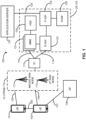
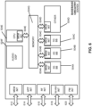
- FIG. 1 illustrates an architecture of a system 100 of a network, in accordance with various embodiments.
- LTE Long Term Evolution
- 3GPP 3rd Generation Partnership Project
- TS Technical specifications
- the example embodiments are not limited in this regard and the described embodiments may apply to other networks that benefit from the principles described herein, such as Fifth Generation (5G) or New Radio (NR) systems, and the like.
- 5G Fifth Generation
- NR New Radio
- any of the UEs 101 and 102 can comprise an IoT UE, which can comprise a network access layer designed for low-power IoT applications utilizing short-lived UE connections.
- An IoT UE can utilize technologies such as M2M or MTC for exchanging data with an MTC server or device via a public land mobile network (PLMN), Proximity-Based Service (ProSe) or device-to-device (D2D) communication, sensor networks, or IoT networks.
- PLMN public land mobile network
- ProSe Proximity-Based Service
- D2D device-to-device
- the M2M or MTC exchange of data may be a machine-initiated exchange of data.
- An IoT network describes interconnecting IoT UEs, which may include uniquely identifiable embedded computing devices (within the Internet infrastructure), with short-lived connections.
- the IoT UEs may execute background applications (for example, keep-alive messages, status updates, etc.) to facilitate the connections
- the UEs 101 and 102 may be configured to connect, for example, communicatively couple, with a radio access network (RAN) - in this embodiment, an Evolved Universal Mobile Telecommunications System (UMTS) Terrestrial Radio Access Network (E-UTRAN) 110.
- RAN radio access network
- E-UTRAN Evolved Universal Mobile Telecommunications System
- the UEs 101 and 102 utilize connections (or channels) 103 and 104, respectively, each of which comprises a physical communications interface or layer (discussed in further detail below).
- channels may refer to any transmission medium, either tangible or intangible, which is used to communicate data or a data stream.
- channel may be synonymous with and/or equivalent to "communications channel,” “data communications channel,” “transmission channel,” “data transmission channel,” “access channel,” “data access channel,” “link,” “data link,” “carrier,” “radiofrequency carrier,” and/or any other like term denoting a pathway or medium through which data is communicated.
- link may refer to a connection between two devices through a Radio Access Technology (RAT) for the purpose of transmitting and receiving information.
- RAT Radio Access Technology
- connections 103 and 104 are illustrated as an air interface to enable communicative coupling, and can be consistent with cellular communications protocols, such as a Global System for Mobile Communications (GSM) protocol, a code-division multiple access (CDMA) network protocol, a Push-to-Talk (PTT) protocol, a PTT over Cellular (POC) protocol, a Universal Mobile Telecommunications System (UMTS) protocol, a 3GPP Long Term Evolution (LTE) protocol, a fifth generation (5G) protocol, a New Radio (NR) protocol, and/or any of the other communications protocols discussed herein.
- GSM Global System for Mobile Communications
- CDMA code-division multiple access
- PTT PTT over Cellular
- UMTS Universal Mobile Telecommunications System
- LTE Long Term Evolution
- 5G fifth generation
- NR New Radio
- the ProSe interface 105 may alternatively be referred to as a sidelink (SL) interface 105 and may comprise one or more logical channels, including but not limited to a Physical Sidelink Control Channel (PSCCH), a Physical Sidelink Shared Channel (PSSCH), a Physical Sidelink Discovery Channel (PSDCH), and a Physical Sidelink Broadcast Channel (PSBCH).
- PSCCH Physical Sidelink Control Channel
- PSSCH Physical Sidelink Shared Channel
- PSDCH Physical Sidelink Discovery Channel
- PSBCH Physical Sidelink Broadcast Channel
- the UE 102 is shown to be configured to access an access point (AP) 106 (also referred to as also referred to as "WLAN node 106", “WLAN 106", “WLAN Termination 106" or “WT 106” or the like) via connection 107.
- the connection 107 can comprise a local wireless connection, such as a connection consistent with any IEEE 802.11 protocol, wherein the AP 106 would comprise a wireless fidelity (WiFi ® ) router.
- WiFi ® wireless fidelity
- the AP 106 is shown to be connected to the Internet without connecting to the core network of the wireless system (described in further detail below).
- the UE 102, RAN 110, and AP 106 may be configured to utilize LTE-WLAN aggregation (LWA) operation and/or WLAN LTE/WLAN Radio Level Integration with IPsec Tunnel (LWIP) operation.
- LWA operation may involve the UE 102 in RRC_CONNECTED being configured by a RAN node 111, 112 to utilize radio resources of LTE and WLAN.
- LWIP operation may involve the UE 102 using WLAN radio resources (for example, connection 107) via Internet Protocol Security (IPsec) protocol tunneling to authenticate and encrypt packets (for example, internet protocol (IP) packets) sent over the connection 107.
- IPsec tunneling may include encapsulating entirety of original IP packets and adding a new packet header thereby protecting the original header of the IP packets.
- the Radio Access Network (RAN) 110 can include one or more access nodes that enable the connections 103 and 104.
- access node may describe equipment that provides the radio baseband functions for data and/or voice connectivity between a network and one or more users.
- These access nodes can be referred to as base stations (BS), NodeBs, evolved NodeBs (eNBs), next Generation NodeBs (gNB), RAN nodes, Road Side Units (RSUs), Transmission Reception Points (TRxPs or TRPs), and so forth, and can comprise ground stations (for example, terrestrial access points) or satellite stations providing coverage within a geographic area (for example, a cell).
- BS base stations
- eNBs evolved NodeBs
- gNB next Generation NodeBs
- RSUs Road Side Units
- TRxPs or TRPs Transmission Reception Points
- any of the RAN nodes 111 and 112 can terminate the air interface protocol and can be the first point of contact for the UEs 101 and 102.
- any of the RAN nodes 111 and 112 can fulfill various logical functions for the RAN 110 including, but not limited to, radio network controller (RNC) functions such as radio bearer management, uplink and downlink dynamic radio resource management and data packet scheduling, and mobility management.
- RNC radio network controller
- the UEs 101 and 102 can be configured to communicate using Orthogonal Frequency-Division Multiplexing (OFDM) communication signals with each other or with any of the RAN nodes 111 and 112 over a multicarrier communication channel in accordance various communication techniques, such as, but not limited to, an Orthogonal Frequency-Division Multiple Access (OFDMA) communication technique (for example, for downlink communications) or a Single Carrier Frequency Division Multiple Access (SC-FDMA) communication technique (for example, for uplink and ProSe or sidelink communications), although the scope of the embodiments is not limited in this respect.
- OFDM signals can comprise a plurality of orthogonal subcarriers.
- a downlink resource grid can be used for downlink transmissions from any of the RAN nodes 111 and 112 to the UEs 101 and 102, while uplink transmissions can utilize similar techniques.
- the grid can be a time-frequency grid, called a resource grid or time-frequency resource grid, which is the physical resource in the downlink in each slot.
- a time-frequency plane representation is a common practice for OFDM systems, which makes it intuitive for radio resource allocation.
- Each column and each row of the resource grid corresponds to one OFDM symbol and one OFDM subcarrier, respectively.
- the duration of the resource grid in the time domain corresponds to one slot in a radio frame.
- the smallest time-frequency unit in a resource grid is denoted as a resource element.
- Each resource grid comprises a number of resource blocks, which describe the mapping of certain physical channels to resource elements.
- Each resource block comprises a collection of resource elements; in the frequency domain, this may represent the smallest quantity of resources that currently can be allocated.
- the physical downlink shared channel may carry user data and higher-layer signaling to the UEs 101 and 102.
- the physical downlink control channel (PDCCH) may carry information about the transport format and resource allocations related to the PDSCH channel, among other things. It may also inform the UEs 101 and 102 about the transport format, resource allocation, and H-ARQ (Hybrid Automatic Repeat Request) information related to the uplink shared channel.
- downlink scheduling (assigning control and shared channel resource blocks to the UE 102 within a cell) may be performed at any of the RAN nodes 111 and 112 based on channel quality information fed back from any of the UEs 101 and 102.
- the downlink resource assignment information may be sent on the PDCCH used for (for example, assigned to) each of the UEs 101 and 102.
- Some embodiments may use concepts for resource allocation for control channel information that are an extension of the above-described concepts.
- some embodiments may utilize an enhanced physical downlink control channel (EPDCCH) that uses PDSCH resources for control information transmission.
- the EPDCCH may be transmitted using one or more enhanced the control channel elements (ECCEs). Similar to above, each ECCE may correspond to nine sets of four physical resource elements known as an enhanced resource element groups (EREGs). An ECCE may have other numbers of EREGs in some situations.
- EPCCH enhanced physical downlink control channel
- ECCEs enhanced the control channel elements
- each ECCE may correspond to nine sets of four physical resource elements known as an enhanced resource element groups (EREGs).
- EREGs enhanced resource element groups
- An ECCE may have other numbers of EREGs in some situations.
- the EPC network 120 comprises the MMEs 121, the S-GW 122, the Packet Data Network (PDN) Gateway (P-GW) 123, and a home subscriber server (HSS) 124.
- the MMEs 121 may be similar in function to the control plane of legacy Serving General Packet Radio Service (GPRS) Support Nodes (SGSN).
- GPRS General Packet Radio Service
- the MMEs 121 may perform various mobility management (MM) procedures to manage mobility aspects in access such as gateway selection and tracking area list management.
- MM also referred to as "EPS MM” or "EMM" in E-UTRAN systems
- EPS MM Packet Data Network
- EMM Mobility Management
- a UE 101, 102 may be in the EMM-DEREGISTERED state and the EMM-IDLE mode and then, by establishing an RRC connection, the UE 101, 102 may change to the EMM-CONNECTED mode in the EMM-DEREGISTERED state.
- the UE 101, 102 may change to the EMM-REGISTERED state and the EMM-CONNECTED mode.
- the network may release the radio connection and the UE 101, 102 may change to EMM-IDLE mode while in the EMM-REGISTERED state.
- the HSS 124 may comprise a database for network users, including subscription-related information to support the network entities' handling of communication sessions.
- the EPC network 120 may comprise one or several HSSs 124, depending on the number of mobile subscribers, on the capacity of the equipment, on the organization of the network, etc.
- the HSS 124 can provide support for routing/roaming, authentication, authorization, naming/addressing resolution, location dependencies, etc.
- the S-GW 122 may terminate the S1 interface 113 towards the RAN 110, and routes data packets between the RAN 110 and the EPC network 120.
- the S-GW 122 may be a local mobility anchor point for inter-RAN node handovers and also may provide an anchor for inter-3GPP mobility. Other responsibilities may include lawful intercept, charging, and some policy enforcement.
- the P-GW 123 may terminate an SGi interface toward a PDN.
- the P-GW 123 may route data packets between the EPC network 123 and e2emal networks such as a network including the application server 130 (alternatively referred to as application function (AF)) via an Internet Protocol (IP) interface 125.
- the application server 130 may be an element offering applications that use IP bearer resources with the core network (for example, UMTS Packet Services (PS) domain, LTE PS data services, etc.).
- PS UMTS Packet Services
- the P-GW 123 is shown to be communicatively coupled to an application server 130 via an IP communications interface 125.
- the application server 130 can also be configured to support one or more communication services (for example, Voice-over-Internet Protocol (VoIP) sessions, PTT sessions, group communication sessions, social networking services, etc.) for the UEs 101 and 102 via the EPC network 120.
- VoIP Voice-over-Internet Protocol
- the P-GW 123 may further be a node for policy enforcement and charging data collection.
- Policy and Charging Enforcement Function (PCRF) 126 is the policy and charging control element of the EPC network 120.
- PCRF Policy and Charging Enforcement Function
- HPLMN Home Public Land Mobile Network
- IP-CAN Internet Protocol Connectivity Access Network
- HPLMN Home Public Land Mobile Network
- V-PCRF Visited PCRF
- VPLMN Visited Public Land Mobile Network
- the PCRF 126 may be communicatively coupled to the application server 130 via the P-GW 123.
- the application server 130 may signal the PCRF 126 to indicate a new service flow and select the appropriate Quality of Service (QoS) and charging parameters.
- the PCRF 126 may provision this rule into a Policy and Charging Enforcement Function (PCEF) (not shown) with the appropriate traffic flow template (TFT) and QoS class of identifier (QCI), which commences the QoS and charging as specified by the application server 130.
- PCEF Policy and Charging Enforcement Function
- TFT traffic flow template
- QCI QoS class of identifier
- the UEs 101, 102 may operate in an enhanced coverage mode or use enhanced coverage functionality to access cell(s) provided by RAN nodes 111, 112.
- the UEs 101, 102 that operate with enhanced coverage may be bandwidth reduced low complexity (BL) UEs 101, 102, which are UEs that can operate in any LTE (or NR) system bandwidth but with a limited channel bandwidth of, for example, 6 physical resource blocks (PRBs) (corresponding to a maximum channel bandwidth available in an LTE system of 1.4 MHz, for example) in downlink and uplink.
- BL bandwidth reduced low complexity
- CE mode A may be used for relatively modest coverage enhancement
- CE mode B may be used for extensive coverage enhancement
- UEs 101, 102 operating in CE mode B may have a maximum PDSCH/PUSCH bandwidth in connected mode for unicast transmission depending on a UE category of the UEs 101, 102.
- a category M1 BL UE operating in CE mode B may have a maximum of 6 PRB bandwidth for each of the PDSCH and PUSCH; a category M2 BL UE operating in CE mode B may have a maximum 24 PRB bandwidth for PDSCH and maximum 6 PRB bandwidth for PUSCH; and a non-BL UE operating in CE mode B may have a maximum 96 PRB bandwidth for PDSCH and maximum 6 PRB bandwidth for PUSCH.
- the UEs 101, 102 may also be Circuit Switched Fallback (CSFB) and/or IP Multimedia Subsystem (IMS)/Circuitry Switched (CS)-voice capable UEs.
- CSFB allows UEs to fall back to using GERAN (Global System for Mobile Communications (GSM)/Enhanced Data Rates for GSM Evolution (EDGE) Radio Access Network), UTRAN (Universal Terrestrial Radio Access Network), or some other legacy system while in E-UTRAN in order to, inter alia, initiate or receive calls via the circuit switched (CS) domain.
- GSM Global System for Mobile Communications
- EDGE Enhanced Data Rates for GSM Evolution
- UTRAN Universal Terrestrial Radio Access Network
- the UEs 101, 102 may perform an access domain selection procedure for UE originating voice calls for deciding whether a call should be serviced in the CS domain or using IMS.
- the access domain selection may be based on, inter alia, a state of the UE 101, 102 in the CS domain (for example, attached, detached), a state of the UE 101, 102 in the IMS (for example, registered or unregistered), a domain used by an existing session/call for the same service, user preferences and/or operator policies, whether the UE 101, 102 supports IMS over PS session, and whether the UE 101, 102 is expected to behave in a "Voice centric" or "Data Centric" way.
- the domain selection for originating voice calls may include setting the UEs, 101, 102 to behave as "Voice centric" or "Data Centric.”
- a UE 101, 102 When a UE 101, 102 is set to "voice centric,” the UE 101, 102 will always try to ensure that voice service is possible. This means that a voice centric UE 101, 102 may reselect to a 2G/3G RAN node (for example, by disabling its E-UTRA capabilities) if voice service in E-UTRAN cannot be provided via CSFB or voice over IMS.
- a UE 101, 102 is set to "data centric," the UEs 101, 102 do not disable the E-UTRAN capability if voice services cannot be obtained. This means that a data centric UE 101, 102 will not reselect to a different RAT even if voice service in E-UTRAN cannot be provided via CSFB or voice over IMS.
- the UE 101, 102 supports CSFB, or the UE 101, 102 is configured to support IMS voice, or both, the UE shall include a "Voice domain preference and UE's usage setting" information element (IE) in an Attach Request, Tracking Area Update (TAU) Request, and Routing Area Update (RAU) Request messages.
- the UE 101, 102 may use the "Voice domain preference and UE's usage setting" IE to signal to the network the UE's usage setting and voice domain preference for E-UTRAN.
- the UE's usage setting indicates whether the UE behaves in a voice centric or data centric way.
- the voice domain preference for E-UTRAN indicates whether the UE is configured as CS Voice only, CS Voice preferred and IMS packet switched (PS) Voice as secondary, IMS PS Voice preferred and CS Voice as secondary, or IMS PS Voice only.
- a change of the UE's usage setting or voice domain preference for E-UTRAN may trigger the UEs 101, 102 to perform a TAU procedure.
- a UE 101, 102 supporting CE mode B may detach and then reattach to the network whenever the UE's usage setting of the UE 101, 102 is changed from "voice centric" to "data centric,” or vice versa, in order to update the UE radio capability information at the MME 121, changing the CE mode B support indication in the UE radio capability information from a value of "not supported” to a value of "supported", or vice versa.
- One drawback of the first embodiments is that such embodiments may be relatively expensive in terms of signaling overhead via the radio interface, including that such embodiments may require retrieval of the full new UE radio capability.
- the MME 121 may update the UE radio capability during a TAU procedure for the UE 101, 102.
- the MME 121 may delete (or mark as deleted) any UE Radio Capability information that it has stored for the UE 101, 102.
- the MME 121 may not send any UE Radio Capability information to the RAN node 111, 112 in that message. This may trigger the E-UTRAN node 111, 112 to request the UE Radio Capability from the UE 101, 102 and to upload it to the MME 121 in an S1 interface UE capability info indication message.
- the UE Radio Capability may include an indication about the support of CE mode B by the UE 101, 102.
- the MME 121 may store the UE Radio Capability information, and include it in further INITIAL CONTEXT SETUP REQUEST or UE RADIO CAPABILITY MATCH REQUEST messages in cases other than an Attach or TAU procedure for the "first TAU following GERAN/UTRAN Attach" and "UE radio capability update” procedure.
- the second embodiments may include an update to section 5.11.2 of 3GPP technical specification (TS) 23.401 version (v) 15.2.0 (2017-12 ) as follows: If the UE is performing an Attach procedure or a Tracking Area Update procedure for the "first TAU following GERAN/UTRAN Attach” or for "UE radio capability update” or for the "UE supporting CE Mode B and changing the UE's usage setting from voice centric to data centric (and vice versa)", the MME shall delete (or mark as deleted) any UE Radio Capability information that it has stored, and, if the MME sends an S1 interface INITIAL CONTEXT SETUP REQUEST or UE RADIO CAPABILITY MATCH REQUEST message during that procedure, the MME shall not send any UE Radio Capability information to the E-UTRAN in that message.
- TS 3GPP technical specification
- v 15.2.0
- the E-UTRAN This triggers the E-UTRAN to request the UE Radio Capability from the UE and to upload it to the MME in the S1 interface UE CAPABILITY INFO INDICATION message.
- the MME stores the UE Radio Capability information, and include it in further INITIAL CONTEXT SETUP REQUEST or UE RADIO CAPABILITY MATCH REQUEST messages in other cases than Attach procedure, Tracking Area Update procedure for the "first TAU following GERAN/UTRAN Attach" and "UE radio capability update” procedure.
- the second embodiments may be better as compared to the first embodiments in terms of radio signaling overhead; however, the second embodiments may only be applicable for a UE 101, 102 that is in EPS Mobility Management (EMM)-Idle mode at the moment when the UE's usage setting of the UE 101, 102 is changed.
- EMM EPS Mobility Management
- the UE radio capability information element (IE) has already been provided by the MME 121 to the E-UTRAN node 111, 112 with an S1 interface INITIAL CONTEXT SETUP REQUEST or UE RADIO CAPABILITY MATCH REQUEST message, then it will not be updated as long as the UE 101, 102 remains in EMM-Connected mode.
- IE UE radio capability information element
- the MME 121 may send an S1 interface INITIAL CONTEXT SETUP REQUEST or UE RADIO CAPABILITY MATCH REQUEST message without including the UE radio capability IE.
- the E-UTRAN node 111, 112 may retrieve the UE radio capability from the UE 101, 102.
- CE mode B restriction parameter a new indicator/flag/parameter called "CE mode B restriction parameter" may be added to the S1-AP message to be sent by MME 121 to the RAN node 111, 112.
- the new indicator/flag/parameter may indicate whether the UE 101, 102 is "restricted” or "not restricted” for CE mode B.
- the S1-AP message may be an INITIAL CONTEXT SETUP REQUEST message, a HANDOVER REQUEST message, a PATH SWITCH REQUEST ACKNOWLEDGE message, a CONNECTION ESTABLISHMENT INDICATION message, a DOWNLINK NAS TRANSPORT message carrying a TAU accept message, or some other like message.
- a variant of the second embodiments may be used for UE 101, 102 that is in EMM-Connected mode when the UE's usage setting is changed from data centric to voice centric, or vice versa, and the UE radio capability IE has already been provided by the MME 121 to the E-UTRAN node 111, 112.
- the MME 121 may receive a TAU request message from the UE 101, 102, where the TAU Request includes "UE radio capability information update needed" indicator.
- the MME 121 may send an S1 interface message, such as a UE RADIO CAPABILITY MATCH REQUEST message without a UE radio capability IE, and instead include an "update needed" indicator.
- the E-UTRAN node 111, 112 may initiate an RRC UE Capability Enquiry procedure to retrieve the UE radio capability from the UE 101, 102, even if the E-UTRAN node 111, 112 has already received a UE radio capability IE from the MME 121 with an earlier S1 interface message (for example, in an INITIAL CONTEXT SETUP REQUEST or UE RADIO CAPABILITY MATCH REQUEST message) or from the UE 101, 102 during an earlier RRC UE Capability Enquiry procedure.
- the UE 101, 102 may provide updated UE Capability information to the E-UTRAN node 111, 112 including the updated CE mode B support indication indicating a value of "not supported” if the UE's usage setting is changed from data centric to voice centric, or a value of "supported", if the UE's usage setting is changed from voice centric to data centric.
- the E-UTRAN node 111, 112 may provide an updated UE radio capability IE to the MME 121 in an S1-AP UE Capability information Indication message.
- the MME 121 may then store the UE radio capability, including the CE mode B support indication, for subsequent accesses by the UE 101, 102.
- the enhanced TAU procedure with "UE radio capability information update needed" indicator discussed with respect to the variation of the second embodiments may be used to update any radio capability parameters.
- a supported UE category, supported bands or band combinations, support of FDD or TDD modes, and the like may be updated using the variant of the second embodiments.
- the UE 101, 102 may need to keep using the previously or currently enabled UE radio capability until the UE 101, 102 has signaled the new UE radio capability to the E-UTRAN node 111,112. If the UE 101, 102 immediately switches to using the new UE radio capability and configures its radiofrequency circuitry and physical layer accordingly, and the E-UTRAN node 111,112 initiates an RRC procedure based on the old UE radio capability that RRC procedure may fail.
- the MME 121 may use the UE's usage setting as indicated by the Attach/TAU request to determine if CE mode B should be restricted, and may inform the E-UTRAN node 111, 112 about the determined restriction whenever the UE's usage setting is changed from voice centric to data centric, or vice versa.
- the UE 101, 102 may send a "Voice domain preference and UE's usage setting" IE in an Attach Request, TAU request, and/or RAU request message to the MME 121 to indicate the UE's usage setting and voice domain preference for E-UTRAN.
- the voice domain preference for E-UTRAN may indicate whether the UE 101, 102 is configured as CS voice only, CS voice preferred and IMS packet switched (PS) voice as secondary, IMS PS voice preferred and CS voice as secondary, or IMS PS voice only.
- PS packet switched
- the UE 101, 102 may send a CE mode B capability to the E-UTRAN node 111, 112 and/or the MME 121 irrespective of its current UE's usage setting ("Voice Centric” or "Data Centric”). If the UE 101, 102 supports "CE mode B" and the UE's usage setting is set to voice centric, then the UE 101, 102 may not operate in CE mode B, may locally disable CE mode B, and the UE 101, 102 may not extend NAS timers and/or may or may not initiate any dedicated bearer establishment (for example, voice over LTE (VoLTE), etc.).
- VoLTE voice over LTE
- One difference between the third embodiments and the second embodiments is that, if the UE 101, 102 supports CE mode B and UE's usage setting is set to voice centric, in the second embodiments the UE 101, 102 does not send a CE mode support capability indicating "CE mode B supported" to the MME 121 during an Attach/TAU/RAU procedure. By contrast, in the third embodiments, the UE 101, 102 always reports its correct capabilities.
- the second embodiments may require updating the UE radio capability stored at the MME 121 when the UE 101, 102 switches from “Voice Centric” to “Data Centric,” and vice versa
- the third embodiments may not require updating the UE radio capability stored at the MME 121 when the UE 101, 102 switches from “Voice Centric” to “Data Centric,” and vice versa.
- the UE 101, 102 may provide two versions of the UE radio capability to the MME 121 during an Attach/TAU/RAU procedure.
- One version of the UE Radio Capability may be used for the voice centric UE's usage setting and a second version of the UE Radio Capability information may be used for the data centric usage setting. This may force the MME 121 to select the correct UE Radio Capability during the TAU/RAU procedure whenever the UE's usage setting is changed from voice centric to data centric, or vice versa.
- the MME 121 may store the two versions of the UE Radio Capability information, and the MME 121 may send the UE Radio Capability corresponding to UE's usage setting to the E-UTRAN 111, 112. Additionally, if the UE 101, 102 supports CE mode B, the UE's usage setting is changed, and the UE 101, 102 is already in the EMM-Connected mode, the MME 121 may send the UE Radio Capability to the E-UTRAN node 111, 112 in a Connection Establishment Indication message, Downlink NAS Transport message, or some other suitable message.
- One difference between the fourth embodiments and the second embodiments may include the use of the two versions of the UE radio capability sent by the UE 101, 102 and stored by the MME 121. Communicating and storing two versions of the UE Radio Capability may require more signaling and storage overhead at the UE 101, 102 and the MME 121.
- the fourth embodiments can be simplified so the second version contain only the changes in the radio capability instead of sending complete radio capability. Additionally, the fourth embodiments may be more generic and can be used if more changes are proposed in future, such as implementing new CE modes, new CE mechanisms, or the like.
- the MME 121 may analyze the UE Radio Capability information and may modify and provide updated UE Radio Capability to the E-UTRAN node 111, 112 whenever the UE's usage setting is changed from voice centric to data centric, or vice versa. Additionally, if the UE 101, 102 supports CE mode B, the UE's usage setting is changed, and the UE 101, 102 is already in the EMM-Connected mode, the MME 121 may send the UE Radio Capability to the E-UTRAN node 111, 112 in a Connection Establishment Indication message, Downlink NAS Transport message, or some other suitable message.
- One drawback of the fifth embodiments is that it may require updates to the implementation/operation of the MME 121 to analyze and/or modify the UE radio capability information.
- a new indicator, flag, parameter called "CE mode B restriction parameter” may be added to an S1-AP message that is sent from MME 121 to E-UTRAN node 111, 112 (e.g. INITIAL CONTEXT SETUP REQUEST message, HANDOVER REQUEST message, PATH SWITCH REQUEST ACKNOWLEDGE message, CONNECTION ESTABLISHMENT INDICATION message, and DOWNLINK NAS TRANSPORT message carrying the TAU ACCEPT message including when the UE initiates a TAU in EMM-Connected mode after PS handover) when the UE's usage setting is changed while the UE 101, 102 is in EMM-Connected mode or EMM-Idle mode.
- INITIAL CONTEXT SETUP REQUEST message HANDOVER REQUEST message, PATH SWITCH REQUEST ACKNOWLEDGE message, CONNECTION ESTABLISHMENT INDICATION message, and DOWNLINK NAS TRANSPORT message carrying the TAU ACCEPT message including when the
- the CE mode B restriction parameter in an S 1-AP message may be set to the first value (for example, “1”, “restricted”, etc.) indicating that the UE 101, 102 is “restricted” for CE mode B.
- CE mode B restriction parameter in an S1-AP message may be set to the second value (e.g. "0", “not restricted”, etc.) indicating that the UE 101, 102 is “not restricted” for CE mode B.
- the "CE mode B restriction parameter” may be included in the various S1-AP messages mentioned previously to indicate whether UE 101, 102 is by subscription “restricted” or “not restricted” for CE mode B.
- values for the CE mode B restriction parameter different than those discussed previously may be used to indicate whether the UE 101, 102 is “restricted” or “not restricted” for CE mode B.
- the "CE mode B restriction parameter” may be a variable of type "enumerated,” for example, the “CE mode B restriction parameter” may be another code point value of the existing "Enhanced Coverage Restricted parameter" included in the S1-AP messages mentioned previously.
- a NAS entity at the UE 101, 102 may disable the usage of CE mode B (for example, due to change from "data centric" to "voice centric,” or vice versa), and the NAS entity may inform an access stratum (AS) entity at the UE 101, 102 not to enable procedures applicable to CE mode B in idle or connected mode, such as for cell reselection, random access, measurement gaps, etc.
- AS access stratum
- the NAS entity may inform the AS entity to enable applicable CE mode B procedures in idle or connected mode.
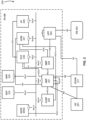
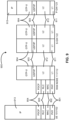
- FIG. 2 illustrates an architecture of a system 200 of a network in accordance with some embodiments.
- the system 200 is shown to include a UE 201, which may be the same or similar to UEs 101 and 102 discussed previously; a RAN node 211, which may be the same or similar to RAN nodes 111 and 112 discussed previously; a Data network (DN) 203, which may be, for example, operator services, Internet access or 3rd party services; and a 5G Core Network (5GC or CN) 220.
- DN Data network
- 5GC or CN 5G Core Network
- the UE 201 may include a "UE's usage setting" IE in Registration Update Request messages (discussed infra). The UE's usage setting indicates whether the UE behaves in a "voice centric" or "data centric” way.
- the CN 220 may include an Authentication Server Function (AUSF) 222; an Access and Mobility Management Function (AMF) 221; a Session Management Function (SMF) 224; a Network Exposure Function (NEF) 223; a Policy Control function (PCF) 226; a Network Function (NF) Repository Function (NRF) 225; a Unified Data Management (UDM) 227; an Application Function (AF) 228; a User Plane Function (UPF) 202; and a Network Slice Selection Function (NSSF) 229.
- AUSF Authentication Server Function
- AMF Access and Mobility Management Function
- SMF Session Management Function
- NEF Network Exposure Function
- PCF Policy Control function
- UDM Unified Data Management
- AF Application Function
- UPF User Plane Function
- NSSF Network Slice Selection Function
- the UPF 202 may act as an anchor point for intra-RAT and inter-RAT mobility, an external PDU session point of interconnect to DN 203, and a branching point to support multi-homed PDU session.
- the UPF 202 may also perform packet routing and forwarding, packet inspection, enforce user plane part of policy rules, lawfully intercept packets (UP collection); traffic usage reporting, perform QoS handling for user plane (e.g. packet filtering, gating, UL/DL rate enforcement), perform Uplink Traffic verification (for example, SDF to QoS flow mapping), transport level packet marking in the uplink and downlink, and downlink packet buffering and downlink data notification triggering.
- UPF 202 may include an uplink classifier to support routing traffic flows to a data network.
- the AMF 221 may be responsible for registration management (for example, for registering UE 201, etc.), connection management, reachability management, mobility management, and lawful interception of AMF-related events, and access authentication and authorization.
- the AMF 221 may be a termination point for the an N11 reference point between the AMF 221 and the SMF 224.
- the AMF 221 may provide transport for Session Management (SM) messages between the UE 201 and the SMF 224, and act as a transparent proxy for routing SM messages.
- SM Session Management
- AMF 221 may also provide transport for short message service (SMS) messages between UE 201 and an SMS function (SMSF) (not shown by FIG. 2 ).
- SMS short message service
- AMF 221 may act as Security Anchor Function (SEA), which may include interaction with the AUSF 222 and the UE 201, receipt of an intermediate key that was established as a result of the UE 201 authentication process. Where USIM based authentication is used, the AMF 221 may retrieve the security material from the AUSF 222. AMF 221 may also include a Security Context Management (SCM) function, which receives a key from the SEA that it uses to derive access-network specific keys.
- SCM Security Context Management
- CM Connection Management
- the signaling connection is used to enable NAS signaling exchange between the UE 201 and the CN 220, and comprises both the AN signaling connection between the UE and the Access Network (AN) (for example, RRC connection or UE-N3IWF connection for Non-3GPP access) and the N2 connection for the UE 201 between the AN (for example, RAN 211) and the AMF 221.
- AN Access Network
- the UE 201 may operate in one of two CM states, CM-IDLE mode or CM-CONNECTED mode.
- the UE 201 When the UE 201 is operating in the CM-IDLE state/mode, the UE 201 may have no NAS signaling connection established with the AMF 221 over the N1 interface, and there may be (R)AN 211 signaling connection (for example, N2 and/or N3 connections) for the UE 201.
- the UE 201 When the UE 201 is operating in the CM-CONNECTED state/mode, the UE 201 may have an established NAS signaling connection with the AMF 221 over the N1 interface, and there may be a (R)AN 211 signaling connection (for example, N2 and/or N3 connections) for the UE 201.
- Establishment of an N2 connection between the (R)AN 211 and the AMF 221 may cause the UE 201 to transition from CM-IDLE mode to CM-CONNECTED mode, and the UE 201 may transition from the CM-CONNECTED mode to the CM-IDLE mode when N2 signaling between the (R)AN 211 and the AMF 221 is released.
- the SMF 224 may be responsible for session management (for example, session establishment, modify and release, including tunnel maintain between UPF and AN node); UE IP address allocation & management (including optional Authorization); Selection and control of UP function; Configures traffic steering at UPF to route traffic to proper destination; termination of interfaces towards Policy control functions; control part of policy enforcement and QoS; lawful intercept (for SM events and interface to LI System); termination of SM parts of NAS messages; downlink Data Notification; initiator of AN specific SM information, sent via AMF over N2 to AN; determine SSC mode of a session.
- session management for example, session establishment, modify and release, including tunnel maintain between UPF and AN node
- UE IP address allocation & management including optional Authorization
- Selection and control of UP function Configures traffic steering at UPF to route traffic to proper destination; termination of interfaces towards Policy control functions; control part of policy enforcement and QoS; lawful intercept (for SM events and interface to LI System); termination of SM parts of NAS
- the SMF 224 may include the following roaming functionality: handle local enforcement to apply QoS SLAs (VPLMN); charging data collection and charging interface (VPLMN); lawful intercept (in VPLMN for SM events and interface to LI System); support for interaction with external DN for transport of signalling for PDU session authorization/authentication by external DN.
- An N16 reference point between two SMFs 224 may be included in the system 200, which may be between another SMF 224 in a visited network and the SMF 224 in the home network in roaming scenarios. Additionally, the SMF 224 may exhibit the Nsmf service-based interface.
- the NEF 223 may provide means for securely exposing the services and capabilities provided by 3GPP network functions for third party, internal exposure/re-exposure, Application Functions (for example, AF 228), edge computing or fog computing systems, etc.
- the NEF 223 may authenticate, authorize, and/or throttle the AFs.
- NEF 223 may also translate information exchanged with the AF 228 and information exchanged with internal network functions. For example, the NEF 223 may translate between an AF-Service-Identifier and an internal 5GC information.
- NEF 223 may also receive information from other network functions (NFs) based on exposed capabilities of other network functions. This information may be stored at the NEF 223 as structured data, or at a data storage NF using a standardized interfaces. The stored information can then be re-exposed by the NEF 223 to other NFs and AFs, and/or used for other purposes such as analytics. Additionally, the NEF 223 may exhibit an Nnef service-based interface.
- the NRF 225 may support service discovery functions, receive NF Discovery Requests from NF instances, and provide the information of the discovered NF instances to the NF instances. NRF 225 also maintains information of available NF instances and their supported services. As used herein, the terms “instantiate”, “instantiation”, and the like may refer to the creation of an instance, and an “instance” may refer to a concrete occurrence of an object, which may occur, for example, during execution of program code. Additionally, the NRF 225 may exhibit the Nnrf service-based interface.
- the UDM 227 may handle subscription-related information to support the network entities' handling of communication sessions, and may store subscription data of UE 201.
- subscription data may be communicated between the UDM 227 and the AMF 221 via an N8 reference point between the UDM 227 and the AMF 221 (not shown by FIG. 2 ).
- the UDM 227 may include two parts, an application FE and a User Data Repository (UDR) (the FE and UDR are not shown by FIG. 2 ).
- the UDR may store subscription data and policy data for the UDM 227 and the PCF 226, and/or structured data for exposure and application data (including Packet Flow Descriptions (PFDs) for application detection, application request information for multiple UEs 201) for the NEF 223.
- PFDs Packet Flow Descriptions
- the Nudr service-based interface may be exhibited by the UDR 221 to allow the UDM 227, PCF 226, and NEF 223 to access a particular set of the stored data, as well as to read, update (for example, add, modify), delete, and subscribe to notification of relevant data changes in the UDR.
- the UDM may include a UDM FE, which is in charge of processing of credentials, location management, subscription management and so on. Several different front ends may serve the same user in different transactions.
- the UDM-FE accesses subscription information stored in the UDR and performs authentication credential processing; user identification handling; access authorization; registration/mobility management; and subscription management.
- the UDR may interact with the SMF 224 via an N10 reference point between the UDM 227 and the SMF 224.
- UDM 227 may also support SMS management, wherein an SMS-FE implements the similar application logic as discussed previously. Additionally, the UDM 227 may exhibit the Nudm service-based interface.
- the AF 228 may provide application influence on traffic routing, access to the Network Capability Exposure (NCE), and interact with the policy framework for policy control.
- the NCE may be a mechanism that allows the 5GC and AF 228 to provide information to each other via NEF 223, which may be used for edge computing implementations.
- the network operator and third party services may be hosted close to the UE 201 access point of attachment to achieve an efficient service delivery through the reduced end-to-end latency and load on the transport network.
- the 5GC may select a UPF 202 close to the UE 201 and execute traffic steering from the UPF 202 to DN 203 via the N6 interface.
- the AF 228 may influence UPF (re)selection and traffic routing. Based on operator deployment, when AF 228 is considered to be a trusted entity, the network operator may permit AF 228 to interact directly with relevant NFs. Additionally, the AF 228 may exhibit an Naf service-based interface.
- the NSSF 229 may select a set of network slice instances serving the UE 201.
- the NSSF 229 may also determine allowed Network Slice Selection Assistance Information (NSSAI) and the mapping to the Subscribed Single-NSSAIs (S-NSSAIs), if needed.
- the NSSF 229 may also determine the AMF set to be used to serve the UE 201, or a list of candidate AMF(s) 221 based on a suitable configuration and possibly by querying the NRF 225.
- the selection of a set of network slice instances for the UE 201 may be triggered by the AMF 221 with which the UE 201 is registered by interacting with the NSSF 229, which may lead to a change of AMF 221.
- the CN 220 may include an SMSF, which may be responsible for SMS subscription checking and verification, and relaying SM messages to/from the UE 201 to/from other entities, such as an SMS-GMSC/IWMSC/SMS-router.
- the SMS may also interact with AMF 221 and UDM 227 for notification procedure that the UE 201 is available for SMS transfer (for example, set a UE not reachable flag, and notifying UDM 227 when UE 201 is available for SMS).
- the CN 220 may also include other elements that are not shown by FIG. 2 , such as a Data Storage system/architecture, a 5G-Equipment Identity Register (5G-EIR), a Security Edge Protection Proxy (SEPP) , and the like.
- the Data Storage system may include a Structured Data Storage network function (SDSF), an Unstructured Data Storage network function (UDSF), and/or the like.
- SDSF Structured Data Storage network function
- UDSF Unstructured Data Storage network function
- Any NF may store and retrieve unstructured data into/from the UDSF (for example, UE contexts), via N18 reference point between any NF and the UDSF (not shown by FIG. 2 ).
- Individual NFs may share a UDSF for storing their respective unstructured data or individual NFs may each have their own UDSF located at or near the individual NFs.
- the UDSF may exhibit an Nudsf service-based interface (not shown by FIG. 2 ).
- the 5G-EIR may be an NF that checks the status of Permanent Equipment Identifiers (PEI) for determining whether particular equipment/entities are blacklisted from the network; and the SEPP may be a non-transparent proxy that performs topology hiding, message filtering, and policing on inter-PLMN control plane interfaces.
- PEI Permanent Equipment Identifiers
- the CN 220 may include an Nx interface, which is an inter-CN interface between the MME (for example, MME 121) and the AMF 221 in order to enable interworking between CN 220 and CN 120.
- Nx interface is an inter-CN interface between the MME (for example, MME 121) and the AMF 221 in order to enable interworking between CN 220 and CN 120.
- Other example interfaces/reference points may include an N5g-eir service-based interface exhibited by a 5G-EIR, an N27 reference point between NRF in the visited network and the NRF in the home network; and an N31 reference point between the NSSF in the visited network and the NSSF in the home network.
- system 200 may include multiple RAN nodes 211 wherein an Xn interface is defined between two or more RAN nodes 211 (for example, gNBs and the like) that connecting to 5GC 220, between a RAN node 211 (for example, gNB) connecting to 5GC 220 and an eNB (for example, a RAN node 111 of FIG. 1 ), and/or between two eNBs connecting to 5GC 220.
- the Xn interface may include an Xn user plane (Xn-U) interface and an Xn control plane (Xn-C) interface.
- the Xn-U may provide non-guaranteed delivery of user plane PDUs and support/provide data forwarding and flow control functionality.
- the Xn-C may provide management and error handling functionality, functionality to manage the Xn-C interface; mobility support for UE 201 in a connected mode (for example, CM-CONNECTED) including functionality to manage the UE mobility for connected mode between one or more RAN nodes 211.
- the mobility support may include context transfer from an old (source) serving RAN node 211 to new (target) serving RAN node 211; and control of user plane tunnels between old (source) serving RAN node 211 to new (target) serving RAN node 211.
- a protocol stack of the Xn-U may include a transport network layer built on Internet Protocol (IP) transport layer, and a GTP-U layer on top of a UDP and/or IP layer(s) to carry user plane PDUs.
- the Xn-C protocol stack may include an application layer signaling protocol (referred to as Xn Application Protocol (Xn-AP)) and a transport network layer that is built on an SCTP layer.
- the SCTP layer may be on top of an IP layer.
- the SCTP layer provides the guaranteed delivery of application layer messages.
- point-to-point transmission is used to deliver the signaling PDUs.
- the Xn-U protocol stack and/or the Xn-C protocol stack may be same or similar to the user plane and/or control plane protocol stack(s) shown and described herein.
- the various components of the core network 120 and 220 may be referred to as "network elements.”
- the term “network element” may describe a physical or virtualized equipment used to provide wired or wireless communication network services.
- the term “network element” may be considered synonymous to and/or referred to as a networked computer, networking hardware, network equipment, router, switch, hub, bridge, radio network controller, radio access network device, gateway, server, virtualized network function (VNF), network functions virtualization infrastructure (NFVI), and/or the like.
- the components of the CNs 120, 220 may be implemented in one physical node or separate physical nodes including components to read and execute instructions from a machine-readable or computer-readable medium (for example, a non-transitory machine-readable storage medium).
- Network Functions Virtualization may be utilized to virtualize any or all of the above described network node functions via executable instructions stored in one or more computer readable storage mediums (described in further detail below).
- a logical instantiation of the CNs 120, 220 may be referred to as a network slice, and a logical instantiation of a portion of the CNs 120, 220 may be referred to as a network sub-slice (for example, a network sub-slice may include the PGW 123 and the PCRF 126).
- NFV architectures and infrastructures may be used to virtualize one or more network functions, alternatively performed by proprietary hardware, onto physical resources comprising a combination of industry-standard server hardware, storage hardware, or switches. In other words, NFV systems can be used to execute virtual or reconfigurable implementations of one or more EPC components/functions.
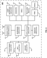
- FIG. 3 illustrates an example of infrastructure equipment 300 in accordance with various embodiments.
- the infrastructure equipment 300 (or "system 300") may be implemented as a base station, radio head, RAN node, etc., such as the RAN nodes 111 and 112, and/or AP 106 shown and described previously.
- the system 300 could be implemented in or by a UE or a core network node/entity.
- the system 300 may include one or more of application circuitry 305, baseband circuitry 304, one or more radio front end modules 315, memory 320, power management integrated circuitry (PMIC) 325, power tee circuitry 330, network controller 335, network interface connector 340, satellite positioning circuitry 345, and user interface 350.
- PMIC power management integrated circuitry
- the circuitry may execute one or more software or firmware programs to provide at least some of the described functionality.
- the term "circuitry” may also refer to a combination of one or more hardware elements (or a combination of circuits used in an electrical or electronic system) with the program code used to carry out the functionality of that program code. In these embodiments, the combination of hardware elements and program code may be referred to as a particular type of circuitry.
- processor circuitry may refer to, is part of, or includes circuitry capable of sequentially and automatically carrying out a sequence of arithmetic or logical operations; recording, storing, and/or transferring digital data.
- processor circuitry may refer to one or more application processors, one or more baseband processors, a physical central processing unit (CPU), a single-core processor, a dual-core processor, a triple-core processor, a quad-core processor, and/or any other device capable of executing or otherwise operating computer-executable instructions, such as program code, software modules, and/or functional processes.
- CPU central processing unit
- Application circuitry 305 may include one or more central processing unit (CPU) cores and one or more of cache memory, low drop-out voltage regulators (LDOs), interrupt controllers, serial interfaces such as SPI, I 2 C or universal programmable serial interface module, real time clock (RTC), timer-counters including interval and watchdog timers, general purpose input/output (I/O or IO), memory card controllers such as Secure Digital (SD/)MultiMediaCard (MMC) or similar, Universal Serial Bus (USB) interfaces, Mobile Industry Processor Interface (MIPI) interfaces and Joint Test Access Group (JTAG) test access ports.
- CPU central processing unit
- LDOs low drop-out voltage regulators
- interrupt controllers serial interfaces such as SPI, I 2 C or universal programmable serial interface module, real time clock (RTC), timer-counters including interval and watchdog timers, general purpose input/output (I/O or IO), memory card controllers such as Secure Digital (SD/)MultiMediaCard (MMC
- the application circuitry 305 may include one or more Intel Pentium ® , Core ® , or Xeon ® processor(s); Advanced Micro Devices (AMD) Ryzen ® processor(s), Accelerated Processing Units (APUs), or Epyc ® processors; and/or the like.
- the system 300 may not utilize application circuitry 305, and instead may include a special-purpose processor/controller to process IP data received from an EPC or 5GC, for example.
- application circuitry 305 may include circuitry such as, but not limited to, one or more a field-programmable devices (FPDs) such as field-programmable gate arrays (FPGAs) and the like; programmable logic devices (PLDs) such as complex PLDs (CPLDs), high-capacity PLDs (HCPLDs), and the like; ASICs such as structured ASICs and the like; programmable SoCs (PSoCs); and the like.
- the circuitry of application circuitry 305 may comprise logic blocks or logic fabric including and other interconnected resources that may be programmed to perform various functions, such as the procedures, methods, functions, etc. of the various embodiments discussed herein.
- the circuitry of application circuitry 305 may include memory cells (for example, erasable programmable read-only memory (EPROM), electrically erasable programmable read-only memory (EEPROM), flash memory, static memory (for example, static random access memory (SRAM), anti-fuses, etc.) used to store logic blocks, logic fabric, data, etc. in lookup-tables (LUTs) and the like.
- memory cells for example, erasable programmable read-only memory (EPROM), electrically erasable programmable read-only memory (EEPROM), flash memory, static memory (for example, static random access memory (SRAM), anti-fuses, etc.) used to store logic blocks, logic fabric, data, etc. in lookup-tables (LUTs) and the like.
- the baseband circuitry 304 may be implemented, for example, as a solder-down substrate including one or more integrated circuits, a single packaged integrated circuit soldered to a main circuit board or a multi-chip module containing two or more integrated circuits.
- baseband circuitry 304 may comprise one or more digital baseband systems, which may be coupled via an interconnect subsystem to a CPU subsystem, an audio subsystem, and an interface subsystem.
- the digital baseband subsystems may also be coupled to a digital baseband interface and a mixed-signal baseband sub-system via another interconnect subsystem.
- the radio front end modules (RFEMs) 315 may comprise a millimeter wave RFEM and one or more sub-millimeter wave radio frequency integrated circuits (RFICs).
- the one or more sub-millimeter wave RFICs may be physically separated from the millimeter wave RFEM.
- the RFICs may include connections to one or more antennas or antenna arrays, and the RFEM may be connected to multiple antennas.
- both millimeter wave and sub-millimeter wave radio functions may be implemented in the same physical radio front end module 315.
- the RFEMs 315 may incorporate both millimeter wave antennas and sub-millimeter wave antennas.
- the memory circuitry 320 may include one or more of volatile memory including dynamic random access memory (DRAM) and/or synchronous dynamic random access memory (SDRAM), and nonvolatile memory (NVM) including high-speed electrically erasable memory (commonly referred to as Flash memory), phase change random access memory (PRAM), magnetoresistive random access memory (MRAM), etc., and may incorporate the three-dimensional (3D) cross-point (XPOINT) memories from Intel ® and Micron ® .
- Memory circuitry 320 may be implemented as one or more of solder down packaged integrated circuits, socketed memory modules and plug-in memory cards.
- the network controller circuitry 335 may provide connectivity to a network using a standard network interface protocol such as Ethernet, Ethernet over GRE Tunnels, Ethernet over Multiprotocol Label Switching (MPLS), or some other suitable protocol.
- Network connectivity may be provided to/from the infrastructure equipment 300 via network interface connector 340 using a physical connection, which may be electrical (commonly referred to as a "copper interconnect"), optical, or wireless.
- the network controller circuitry 335 may include one or more dedicated processors and/or FPGAs to communicate using one or more of the aforementioned protocol. In some implementations, the network controller circuitry 335 may include multiple controllers to provide connectivity to other networks using the same or different protocols.
- the positioning circuitry 345 which may include circuitry to receive and decode signals transmitted by one or more navigation satellite constellations of a global navigation satellite system (GNSS).
- GNSS global navigation satellite system
- Examples of navigation satellite constellations (or GNSS) may include United States' Global Positioning System (GPS), Russia's Global Navigation System (GLONASS), the European Union's Galileo system, China's BeiDou Navigation Satellite System, a regional navigation system or GNSS augmentation system (for example, Navigation with Indian Constellation (NAVIC), Japan's Quasi-Zenith Satellite System (QZSS), France's Doppler Orbitography and Radio-positioning Integrated by Satellite (DORIS), etc.), or the like.
- GPS Global Positioning System
- GLONASS Global Navigation System
- Galileo system China's BeiDou Navigation Satellite System
- a regional navigation system or GNSS augmentation system for example, Navigation with Indian Constellation (NAVIC), Japan's Quasi-Zenith Satellite System (
- the positioning circuitry 345 may comprise various hardware elements (for example, including hardware devices such as switches, filters, amplifiers, antenna elements, and the like to facilitate the communications over-the-air (OTA) communications) to communicate with components of a positioning network, such as navigation satellite constellation nodes.
- OTA over-the-air
- GNSS nodes may provide positioning services by continuously transmitting or broadcasting GNSS signals along a line of sight, which may be used by GNSS receivers (for example, positioning circuitry 345 and/or positioning circuitry implemented by UEs 101, 102, or the like) to determine their GNSS position.
- the GNSS signals may include a pseudorandom code (for example, a sequence of ones and zeros) that is known to the GNSS receiver and a message that includes a time of transmission (ToT) of a code epoch (for example, a defined point in the pseudorandom code sequence) and the GNSS node position at the ToT.
- pseudorandom code for example, a sequence of ones and zeros
- ToT time of transmission
- code epoch for example, a defined point in the pseudorandom code sequence
- the GNSS receivers may monitor/measure the GNSS signals transmitted/broadcasted by a plurality of GNSS nodes (for example, four or more satellites) and solve various equations to determine a corresponding GNSS position (for example, a spatial coordinate).
- the GNSS receivers also implement clocks that are typically less stable and less precise than the atomic clocks of the GNSS nodes, and the GNSS receivers may use the measured GNSS signals to determine the GNSS receivers' deviation from true time (for example, an offset of the GNSS receiver clock relative to the GNSS node time).
- the positioning circuitry 345 may include a Micro-Technology for Positioning, Navigation, and Timing (Micro-PNT) IC that uses a master timing clock to perform position tracking/estimation without GNSS assistance.
- Micro-PNT Micro-Technology for Positioning, Navigation, and Timing
- the GNSS receivers may measure the time of arrivals (ToAs) of the GNSS signals from the plurality of GNSS nodes according to its own clock.
- the GNSS receivers may determine ToF values for each received GNSS signal from the ToAs and the ToTs, and then may determine, from the ToFs, a three-dimensional (3D) position and clock deviation.
- the 3D position may then be converted into a latitude, longitude and altitude.
- the positioning circuitry 345 may provide data to application circuitry 305 which may include one or more of position data or time data.
- Application circuitry 305 may use the time data to synchronize operations with other radio base stations (for example, RAN nodes 111, 112, 211 or the like).
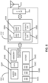
- FIG. 4 illustrates an example of a platform 400 (or "device 400") in accordance with various embodiments.
- the computer platform 400 may be suitable for use as UEs 101, 102, 201, application servers 130, and/or any other element/device discussed herein.
- the platform 400 may include any combinations of the components shown in the example.
- the components of platform 400 may be implemented as integrated circuits (ICs), portions thereof, discrete electronic devices, or other modules, logic, hardware, software, firmware, or a combination thereof adapted in the computer platform 400, or as components otherwise incorporated within a chassis of a larger system.
- the block diagram of FIG. 4 is intended to show a high level view of components of the computer platform 400. However, some of the components shown may be omitted, additional components may be present, and different arrangement of the components shown may occur in other implementations.
- the application circuitry 405 may include circuitry such as, but not limited to single-core or multi-core processors and one or more of cache memory, low drop-out voltage regulators (LDOs), interrupt controllers, serial interfaces such as serial peripheral interface (SPI), inter-integrated circuit (I 2 C) or universal programmable serial interface circuit, real time clock (RTC), timer-counters including interval and watchdog timers, general purpose input-output (IO), memory card controllers such as secure digital / multi-media card (SD/MMC) or similar, universal serial bus (USB) interfaces, mobile industry processor interface (MIPI) interfaces and Joint Test Access Group (JTAG) test access ports.
- LDOs low drop-out voltage regulators
- interrupt controllers serial interfaces such as serial peripheral interface (SPI), inter-integrated circuit (I 2 C) or universal programmable serial interface circuit, real time clock (RTC), timer-counters including interval and watchdog timers, general purpose input-output (IO), memory card controllers such as secure digital
- the processor(s) may include any combination of general-purpose processors and/or dedicated processors (for example, graphics processors, application processors, etc.).
- the processors (or cores) may be coupled with or may include memory/storage and may be configured to execute instructions stored in the memory/storage to enable various applications or operating systems to run on the platform 400.
- processors of application circuitry 305/405 may process IP data packets received from an EPC or 5GC.
- Application circuitry 405 be or include a microprocessor, a multi-core processor, a multithreaded processor, an ultra-low voltage processor, an embedded processor, or other known processing element.
- the application circuitry 405 may include an Intel ® Architecture Core TM based processor, such as a Quark TM , an Atom TM , an i3, an i5, an i7, or an MCU-class processor, or another such processor available from Intel ® Corporation, Santa Clara, CA.
- the processors of the application circuitry 405 may also be one or more of Advanced Micro Devices (AMD) Ryzen ® processor(s) or Accelerated Processing Units (APUs); A5-A9 processor(s) from Apple ® Inc., Qualcomm TM processor(s) from Qualcomm ® Technologies, Inc., Texas Instruments, Inc. ® Open Multimedia Applications Platform (OMAP) TM processor(s); a MIPS-based design from MIPS Technologies, Inc; an ARM-based design licensed from ARM Holdings, Ltd.; or the like.
- AMD Advanced Micro Devices
- APUs Accelerated Processing Units
- A5-A9 processor(s) from Apple ® Inc.
- Snapdragon TM processor(s) from Qualcomm ® Technologies, Inc. Texas Instruments, Inc.
- OMAP Open Multimedia Applications Platform
- the application circuitry 405 may be a part of a system on a chip (SoC) in which the application circuitry 405 and other components are formed into a single integrated circuit, or a single package, such as the Edison TM or Galileo TM SoC boards from Intel ® Corporation.
- SoC system on a chip
- application circuitry 405 may include circuitry such as, but not limited to, one or more a field-programmable devices (FPDs) such as FPGAs and the like; programmable logic devices (PLDs) such as complex PLDs (CPLDs), high-capacity PLDs (HCPLDs), and the like; ASICs such as structured ASICs and the like; programmable SoCs (PSoCs); and the like.
- FPDs field-programmable devices
- PLDs programmable logic devices
- CPLDs complex PLDs
- HPLDs high-capacity PLDs
- PSoCs programmable SoCs
- the circuitry of application circuitry 405 may comprise logic blocks or logic fabric including and other interconnected resources that may be programmed to perform various functions, such as the procedures, methods, functions, etc. of the various embodiments discussed herein.
- the circuitry of application circuitry 405 may include memory cells (for example, erasable programmable read-only memory (EPROM), electrically erasable programmable read-only memory (EEPROM), flash memory, static memory (for example, static random access memory (SRAM), anti-fuses, etc.) used to store logic blocks, logic fabric, data, etc. in lookup-tables (LUTs) and the like.
- memory cells for example, erasable programmable read-only memory (EPROM), electrically erasable programmable read-only memory (EEPROM), flash memory, static memory (for example, static random access memory (SRAM), anti-fuses, etc.) used to store logic blocks, logic fabric, data, etc. in lookup-tables (LUTs) and the like.
- the baseband circuitry 404 may be implemented, for example, as a solder-down substrate including one or more integrated circuits, a single packaged integrated circuit soldered to a main circuit board or a multi-chip module containing two or more integrated circuits.
- baseband circuitry 404 may comprise one or more digital baseband systems, which may be coupled via an interconnect subsystem to a CPU subsystem, an audio subsystem, and an interface subsystem.
- the digital baseband subsystems may also be coupled to a digital baseband interface and a mixed-signal baseband sub-system via another interconnect subsystem.
- Each of the interconnect subsystems may include a bus system, point-to-point connections, network-on-chip (NOC) structures, and/or some other suitable bus or interconnect technology, such as those discussed herein.
- the audio sub-system may include digital signal processing circuitry, buffer memory, program memory, speech processing accelerator circuitry, data converter circuitry such as analog-to-digital and digital-to-analog converter circuitry, analog circuitry including one or more of amplifiers and filters, and/or other like components.
- baseband circuitry 404 may include protocol processing circuitry with one or more instances of control circuitry (not shown) to provide control functions for the digital baseband circuitry and/or radio frequency circuitry (for example, the radio front end modules 415).
- the radio front end modules (RFEMs) 415 may comprise a millimeter wave RFEM and one or more sub-millimeter wave radio frequency integrated circuits (RFICs).
- the one or more sub-millimeter wave RFICs may be physically separated from the millimeter wave RFEM.
- the RFICs may include connections to one or more antennas or antenna arrays, and the RFEM may be connected to multiple antennas.
- both millimeter wave and sub-millimeter wave radio functions may be implemented in the same physical radio front end module 415.
- the RFEMs 415 may incorporate both millimeter wave antennas and sub-millimeter wave antennas.
- the memory circuitry 420 may include any number and type of memory devices used to provide for a given amount of system memory.
- the memory circuitry 420 may include one or more of volatile memory including be random access memory (RAM), dynamic RAM (DRAM) and/or synchronous dynamic RAM (SDRAM), and nonvolatile memory (NVM) including high-speed electrically erasable memory (commonly referred to as Flash memory), phase change random access memory (PRAM), magnetoresistive random access memory (MRAM), etc.
- RAM random access memory
- DRAM dynamic RAM
- SDRAM synchronous dynamic RAM
- NVM nonvolatile memory
- Flash memory high-speed electrically erasable memory
- PRAM phase change random access memory
- MRAM magnetoresistive random access memory
- the memory circuitry 420 may be developed in accordance with a Joint Electron Devices Engineering Council (JEDEC) low power double data rate (LPDDR)-based design, such as LPDDR2, LPDDR3, LPDDR4, or the like.
- JEDEC Joint Electron
- Memory circuitry 320 may be implemented as one or more of solder down packaged integrated circuits, single die package (SDP), dual die package (DDP) or quad die package (Q17P), socketed memory modules, dual inline memory modules (DIMMs) including microDIMMs or MiniDIMMs, and/or soldered onto a motherboard via a ball grid array (BGA).
- the memory circuitry 420 s storage 108 may be on-die memory or registers associated with the application circuitry 405.
- memory circuitry 420 may include one or more mass storage devices , which may include, inter alia, a solid state disk drive (SSDD), hard disk drive (HDD), a micro HDD, resistance change memories, phase change memories, holographic memories, or chemical memories, among others.
- SSDD solid state disk drive
- HDD hard disk drive
- micro HDD micro HDD
- resistance change memories phase change memories
- holographic memories holographic memories
- chemical memories among others.
- the computer platform 400 may incorporate the three-dimensional (3D) cross-point (XPOINT) memories from Intel ® and Micron ® .
- Removable memory circuitry 423 may include devices, circuitry, enclosures/housings, ports or receptacles, etc. used to coupled portable data storage devices with the platform 400. These portable data storage devices may be used for mass storage purposes, and may include, for example, flash memory cards (for example, Secure Digital (SD) cards, microSD cards, xD picture cards, and the like), and USB flash drives, optical discs, external HDDs, and the like.
- flash memory cards for example, Secure Digital (SD) cards, microSD cards, xD picture cards, and the like
- USB flash drives for example, optical discs, external HDDs, and the like.
- the platform 400 may also include interface circuitry (not shown) that is used to connect external devices with the platform 400.
- the external devices connected to the platform 400 via the interface circuitry may include sensors 421, such as accelerometers, level sensors, flow sensors, temperature sensors, pressure sensors, barometric pressure sensors, and the like.
- the interface circuitry may be used to connect the platform 400 to electro-mechanical components (EMCs) 422, which may allow platform 400 to change its state, position, and/or orientation, or move or control a mechanism or system.
- EMCs electro-mechanical components
- the EMCs 422 may include one or more power switches, relays including electromechanical relays (EMRs) and/or solid state relays (SSRs), actuators (for example, valve actuators, etc.), an audible sound generator, a visual warning device, motors (for example, DC motors, stepper motors, etc.), wheels, thrusters, propellers, claws, clamps, hooks, and/or other like electro-mechanical components.
- EMCs electromechanical relays
- SSRs solid state relays
- actuators for example, valve actuators, etc.
- an audible sound generator for example, a visual warning device
- motors for example, DC motors, stepper motors, etc.
- wheels thrusters, propellers, claws, clamps, hooks, and/or other like electro-mechanical components.
- platform 400 may be configured to operate one or more EMCs 422 based on one or more captured events and/or instructions or control signals received from a service provider and/or various clients.
- the interface circuitry may connect the platform 400 with positioning circuitry 445, which may be the same or similar as the positioning circuitry 445 discussed with regard to FIG. 3 .
- the interface circuitry may connect the platform 400 with near-field communication (NFC) circuitry 440, which may include an NFC controller coupled with an antenna element and a processing device.
- NFC circuitry 440 may be configured to read electronic tags and/or connect with another NFC-enabled device.
- the driver circuitry 446 may include software and hardware elements that operate to control particular devices that are embedded in the platform 400, attached to the platform 400, or otherwise communicatively coupled with the platform 400.
- the driver circuitry 446 may include individual drivers allowing other components of the platform 400 to interact or control various input/output (I/O) devices that may be present within, or connected to, the platform 400.
- I/O input/output
- driver circuitry 446 may include a display driver to control and allow access to a display device, a touchscreen driver to control and allow access to a touchscreen interface of the platform 400, sensor drivers to obtain sensor readings of sensors 421 and control and allow access to sensors 421, EMC drivers to obtain actuator positions of the EMCs 422 and/or control and allow access to the EMCs 422, a camera driver to control and allow access to an embedded image capture device, audio drivers to control and allow access to one or more audio devices.
- a display driver to control and allow access to a display device
- a touchscreen driver to control and allow access to a touchscreen interface of the platform 400
- sensor drivers to obtain sensor readings of sensors 421 and control and allow access to sensors 421
- EMC drivers to obtain actuator positions of the EMCs 422 and/or control and allow access to the EMCs 422
- a camera driver to control and allow access to an embedded image capture device
- audio drivers to control and allow access to one or more audio devices.
- the power management integrated circuitry (PMIC) 425 may manage power provided to various components of the platform 400.
- the PMIC 425 may control power-source selection, voltage scaling, battery charging, or DC-to-DC conversion.
- the PMIC 425 may often be included when the platform 400 is capable of being powered by a battery 430, for example, when the device is included in a UE 101, 102, 201.
- the PMIC 425 may control, or otherwise be part of, various power saving mechanisms of the platform 400. For example, if the platform 400 is in an RRC_Connected state, where it is still connected to the RAN node as it expects to receive traffic shortly, then it may enter a state known as Discontinuous Reception Mode (DRX) after a period of inactivity. During this state, the platform 400 may power down for brief intervals of time and thus save power. If there is no data traffic activity for an extended period of time, then the platform 400 may transition off to an RRC_Idle state, where it disconnects from the network and does not perform operations such as channel quality feedback, handover, etc.
- DRX Discontinuous Reception Mode
- the platform 400 goes into a very low power state and it performs paging where again it periodically wakes up to listen to the network and then powers down again.
- the platform 400 may not receive data in this state, in order to receive data, it must transition back to RRC_Connected state.
- An additional power saving mode may allow a device to be unavailable to the network for periods longer than a paging interval (ranging from seconds to a few hours). During this time, the device is totally unreachable to the network and may power down completely. Any data sent during this time incurs a large delay and it is assumed the delay is acceptable.
- a battery 430 may power the platform 400, although in some examples the platform 400 may be mounted deployed in a fixed location, and may have a power supply coupled to an electrical grid.
- the battery 430 may be a lithium ion battery, a metal-air battery, such as a zinc-air battery, an aluminum-air battery, a lithium-air battery, and the like. In some implementations, such as in V2X applications, the battery 430 may be a typical lead-acid automotive battery.
- the battery 430 may be a "smart battery,” which includes or is coupled with a Battery Management System (BMS) or battery monitoring integrated circuitry.
- BMS Battery Management System
- the BMS may be included in the platform 400 to track the state of charge (SoCh) of the battery 430.
- the BMS may be used to monitor other parameters of the battery 430 to provide failure predictions, such as the state of health (SoH) and the state of function (SoF) of the battery 430.
- the BMS may communicate the information of the battery 430 to the application circuitry 405 or other components of the platform 400.
- the BMS may also include an analog-to-digital (ADC) convertor that allows the application circuitry 405 to directly monitor the voltage of the battery 430 or the current flow from the battery 430.
- the battery parameters may be used to determine actions that the platform 400 may perform, such as transmission frequency, network operation, sensing frequency, and the like.
- a power block, or other power supply coupled to an electrical grid may be coupled with the BMS to charge the battery 430.
- the power block 128 may be replaced with a wireless power receiver to obtain the power wirelessly, for example, through a loop antenna in the computer platform 400.
- a wireless battery charging circuit may be included in the BMS. The specific charging circuits chosen may depend on the size of the battery 430, and thus, the current required.
- the charging may be performed using the Airfuel standard promulgated by the Airfuel Alliance, the Qi wireless charging standard promulgated by the Wireless Power Consortium, or the Rezence charging standard, promulgated by the Alliance for Wireless Power, among others.
- a suitable bus technology may include any number of technologies, including industry standard architecture (ISA), extended ISA (EISA), peripheral component interconnect (PCI), peripheral component interconnect extended (PCIx), PCI express (PCIe), a Time-Trigger Protocol (TTP) system, or a FlexRay system, or any number of other technologies.
- the bus may be a proprietary bus, for example, used in a SoC based system.
- Other bus systems may be included, such as an I 2 C interface, an SPI interface, point to point interfaces, and a power bus, among others.
- FIG. 5 illustrates example components of baseband circuitry 304/404 and radio front end modules (RFEM) 315/415 in accordance with some embodiments.
- the RFEM 315/415 may include Radio Frequency (RF) circuitry 506, front-end module (FEM) circuitry 508, one or more antennas 510 coupled together at least as shown.
- RF Radio Frequency
- FEM front-end module
- the baseband circuitry 304/404 may include circuitry such as, but not limited to, one or more single-core or multi-core processors.
- the baseband circuitry 304/404 may include one or more baseband processors or control logic to process baseband signals received from a receive signal path of the RF circuitry 506 and to generate baseband signals for a transmit signal path of the RF circuitry 506.
- Baseband processing circuity 304/404 may interface with the application circuitry 305/405 for generation and processing of the baseband signals and for controlling operations of the RF circuitry 506.
- the baseband circuitry 304/404 may include a third generation (3G) baseband processor 504A, a fourth generation (4G) baseband processor 504B, a fifth generation (5G) baseband processor 504C, or other baseband processor(s) 504D for other existing generations, generations in development or to be developed in the future (for example, second generation (2G), si5h generation (6G), etc.).
- the baseband circuitry 304/404 (for example, one or more of baseband processors 504A-D) may handle various radio control functions that enable communication with one or more radio networks via the RF circuitry 506.
- baseband processors 504A-D may be included in modules stored in the memory 504G and executed via a Central Processing Unit (CPU) 504E.
- the radio control functions may include, but are not limited to, signal modulation/demodulation, encoding/decoding, radio frequency shifting, etc.
- modulation/demodulation circuitry of the baseband circuitry 304/404 may include Fast-Fourier Transform (FFT), precoding, or constellation mapping/demapping functionality.
- FFT Fast-Fourier Transform
- encoding/decoding circuitry of the baseband circuitry 304/404 may include convolution, tail-biting convolution, turbo, Viterbi, or Low Density Parity Check (LDPC) encoder/decoder functionality.
- LDPC Low Density Parity Check
- the baseband circuitry 304/404 may include one or more audio digital signal processor(s) (DSP) 504F.
- the audio DSP(s) 504F may be include elements for compression/decompression and echo cancellation and may include other suitable processing elements in other embodiments.
- Components of the baseband circuitry may be suitably combined in a single chip, a single chipset, or disposed on a same circuit board in some embodiments.
- some or all of the constituent components of the baseband circuitry 304/404 and the application circuitry 305/405 may be implemented together such as, for example, on a system on a chip (SOC).
- SOC system on a chip
- the baseband circuitry 304/404 may provide for communication compatible with one or more radio technologies.
- the baseband circuitry 304/404 may support communication with an evolved universal terrestrial radio access network (EUTRAN) or other wireless metropolitan area networks (WMAN), a wireless local area network (WLAN), a wireless personal area network (WPAN).
- EUTRAN evolved universal terrestrial radio access network
- WMAN wireless metropolitan area networks
- WLAN wireless local area network
- WPAN wireless personal area network
- multi-mode baseband circuitry Embodiments in which the baseband circuitry 304/404 is configured to support radio communications of more than one wireless protocol.
- RF circuitry 506 may enable communication with wireless networks using modulated electromagnetic radiation through a non-solid medium.
- the RF circuitry 506 may include switches, filters, amplifiers, etc. to facilitate the communication with the wireless network.
- RF circuitry 506 may include a receive signal path which may include circuitry to down-convert RF signals received from the FEM circuitry 508 and provide baseband signals to the baseband circuitry 304/404.
- RF circuitry 506 may also include a transmit signal path which may include circuitry to up-convert baseband signals provided by the baseband circuitry 304/404 and provide RF output signals to the FEM circuitry 508 for transmission.
- the receive signal path of the RF circuitry 506 may include mixer circuitry 506a, amplifier circuitry 506b and filter circuitry 506c.
- the transmit signal path of the RF circuitry 506 may include filter circuitry 506c and mixer circuitry 506a.
- RF circuitry 506 may also include synthesizer circuitry 506d for synthesizing a frequency for use by the mixer circuitry 506a of the receive signal path and the transmit signal path.
- the mixer circuitry 506a of the receive signal path may be configured to down-convert RF signals received from the FEM circuitry 508 based on the synthesized frequency provided by synthesizer circuitry 506d.
- the amplifier circuitry 506b may be configured to amplify the down-converted signals and the filter circuitry 506c may be a low-pass filter (LPF) or band-pass filter (BPF) configured to remove unwanted signals from the down-converted signals to generate output baseband signals.
- Output baseband signals may be provided to the baseband circuitry 304/404 for further processing.
- the output baseband signals may be zero-frequency baseband signals, although this is not a requirement.
- mixer circuitry 506a of the receive signal path may comprise passive mixers, although the scope of the embodiments is not limited in this respect.
- the mixer circuitry 506a of the transmit signal path may be configured to up-convert input baseband signals based on the synthesized frequency provided by the synthesizer circuitry 506d to generate RF output signals for the FEM circuitry 508.
- the baseband signals may be provided by the baseband circuitry 304/404 and may be filtered by filter circuitry 506c.
- the mixer circuitry 506a of the receive signal path and the mixer circuitry 506a of the transmit signal path may include two or more mixers and may be arranged for quadrature downconversion and upconversion, respectively.
- the mixer circuitry 506a of the receive signal path and the mixer circuitry 506a of the transmit signal path may include two or more mixers and may be arranged for image rejection (for example, Hartley image rejection).
- the mixer circuitry 506a of the receive signal path and the mixer circuitry 506a may be arranged for direct downconversion and direct upconversion, respectively.
- the mixer circuitry 506a of the receive signal path and the mixer circuitry 506a of the transmit signal path may be configured for super-heterodyne operation.
- the output baseband signals and the input baseband signals may be analog baseband signals, although the scope of the embodiments is not limited in this respect.
- the output baseband signals and the input baseband signals may be digital baseband signals.
- the RF circuitry 506 may include analog-to-digital converter (ADC) and digital-to-analog converter (DAC) circuitry and the baseband circuitry 304/404 may include a digital baseband interface to communicate with the RF circuitry 506.
- ADC analog-to-digital converter
- DAC digital-to-analog converter
- a separate radio IC circuitry may be provided for processing signals for each spectrum, although the scope of the embodiments is not limited in this respect.
- the synthesizer circuitry 506d may be a fractional-N synthesizer or a fractional N/N+1 synthesizer, although the scope of the embodiments is not limited in this respect as other types of frequency synthesizers may be suitable.
- synthesizer circuitry 506d may be a delta-sigma synthesizer, a frequency multiplier, or a synthesizer comprising a phase-locked loop with a frequency divider.
- the synthesizer circuitry 506d may be configured to synthesize an output frequency for use by the mixer circuitry 506a of the RF circuitry 506 based on a frequency input and a divider control input. In some embodiments, the synthesizer circuitry 506d may be a fractional N/N+1 synthesizer.
- frequency input may be provided by a voltage controlled oscillator (VCO), although that is not a requirement.
- VCO voltage controlled oscillator
- Divider control input may be provided by either the baseband circuitry 304/404 or the applications processor 305/405 depending on the desired output frequency.
- a divider control input (for example, N) may be determined from a look-up table based on a channel indicated by the applications processor 305/405.
- Synthesizer circuitry 506d of the RF circuitry 506 may include a divider, a delay-locked loop (DLL), a multiplexer and a phase accumulator.
- the divider may be a dual modulus divider (DMD) and the phase accumulator may be a digital phase accumulator (DPA).
- the DMD may be configured to divide the input signal by either N or N+1 (for example, based on a carry out) to provide a fractional division ratio.
- the DLL may include a set of cascaded, tunable, delay elements, a phase detector, a charge pump and a D-type flip-flop.
- the delay elements may be configured to break a VCO period up into Nd equal packets of phase, where Nd is the number of delay elements in the delay line.
- Nd is the number of delay elements in the delay line.
- synthesizer circuitry 506d may be configured to generate a carrier frequency as the output frequency, while in other embodiments, the output frequency may be a multiple of the carrier frequency (for example, twice the carrier frequency, four times the carrier frequency) and used in conjunction with quadrature generator and divider circuitry to generate multiple signals at the carrier frequency with multiple different phases with respect to each other.
- the output frequency may be a LO frequency (fLO).
- the RF circuitry 506 may include an IQ/polar converter.
- FEM circuitry 508 may include a receive signal path which may include circuitry configured to operate on RF signals received from one or more antennas 510, amplify the received signals and provide the amplified versions of the received signals to the RF circuitry 506 for further processing.
- FEM circuitry 508 may also include a transmit signal path which may include circuitry configured to amplify signals for transmission provided by the RF circuitry 506 for transmission by one or more of the one or more antennas 510.
- the amplification through the transmit or receive signal paths may be done solely in the RF circuitry 506, solely in the FEM 508, or in both the RF circuitry 506 and the FEM 508.
- the FEM circuitry 508 may include a TX/RX switch to switch between transmit mode and receive mode operation.
- the FEM circuitry may include a receive signal path and a transmit signal path.
- the receive signal path of the FEM circuitry may include an LNA to amplify received RF signals and provide the amplified received RF signals as an output (for example, to the RF circuitry 506).
- the transmit signal path of the FEM circuitry 508 may include a power amplifier (PA) to amplify input RF signals (for example, provided by RF circuitry 506), and one or more filters to generate RF signals for subsequent transmission (for example, by one or more of the one or more antennas 510).
- PA power amplifier
- Processors of the application circuitry 305/405 and processors of the baseband circuitry 304/404 may be used to execute elements of one or more instances of a protocol stack.
- processors of the baseband circuitry 304/404 may be used execute Layer 3, Layer 2, or Layer 1 functionality, while processors of the baseband circuitry 304/404 may utilize data (for example, packet data) received from these layers and further execute Layer 4 functionality (for example, transmission communication protocol (TCP) and user datagram protocol (UDP) layers).
- Layer 3 may comprise a radio resource control (RRC) layer, described in further detail below.
- RRC radio resource control
- Layer 2 may comprise a medium access control (MAC) layer, a radio link control (RLC) layer, and a packet data convergence protocol (PDCP) layer, described in further detail below.
- Layer 1 may comprise a physical (PHY) layer of a UE/RAN node, described in further detail below.
- FIG. 6 illustrates example interfaces of baseband circuitry in accordance with some embodiments.
- the baseband circuitry 304/404 of FIGS. 3-4 may comprise processors 504A-504E and a memory 504G utilized by said processors.
- Each of the processors 504A-504E may include a memory interface, 604A-604E, respectively, to send/receive data to/from the memory 504G.
- the baseband circuitry 304/404 may further include one or more interfaces to communicatively couple to other circuitries/devices, such as a memory interface 612 (for example, an interface to send/receive data to/from memory external to the baseband circuitry 304/404), an application circuitry interface 614 (for example, an interface to send/receive data to/from the application circuitry 305/405 of FIGS. 3-4 ), an RF circuitry interface 616 (for example, an interface to send/receive data to/from RF circuitry 506 of FIG.
- a memory interface 612 for example, an interface to send/receive data to/from memory external to the baseband circuitry 304/404
- an application circuitry interface 614 for example, an interface to send/receive data to/from the application circuitry 305/405 of FIGS. 3-4
- an RF circuitry interface 616 for example, an interface to send/receive data to/from RF circuitry 506 of FIG.
- a wireless hardware connectivity interface 618 for example, an interface to send/receive data to/from Near Field Communication (NFC) components, Bluetooth ® components (for example, Bluetooth ® Low Energy), Wi-Fi ® components, and other communication components), and a power management interface 620 (for example, an interface to send/receive power or control signals to/from the PMIC 425.
- NFC Near Field Communication
- Bluetooth ® components for example, Bluetooth ® Low Energy
- Wi-Fi ® components for example, Wi-Fi ® components, and other communication components
- a power management interface 620 for example, an interface to send/receive power or control signals to/from the PMIC 425.
- FIG. 7 is a block diagram illustrating components, according to some example embodiments, able to read instructions from a machine-readable or computer-readable medium (for example, a non-transitory machine-readable storage medium) and perform any one or more of the methodologies discussed herein.
- FIG. 7 shows a diagrammatic representation of hardware resources 700 including one or more processors (or processor cores) 710, one or more memory/storage devices 720, and one or more communication resources 730, each of which may be communicatively coupled via a bus 740.
- computing resource may refer to a physical or virtual device, a physical or virtual component within a computing environment, and/or physical or virtual component within a particular device, such as computer devices, mechanical devices, memory space, processor/CPU time and/or processor/CPU usage, processor and accelerator loads, hardware time or usage, electrical power, input/output operations, ports or network sockets, channel/link allocation, throughput, memory usage, storage, network, database and applications, and/or the like.
- node virtualization for example, NFV
- a hypervisor 702 may be executed to provide an execution environment for one or more network slices/sub-slices to utilize the hardware resources 700.
- a "virtualized resource” may refer to compute, storage, and/or network resources provided by virtualization infrastructure to an application, device, system, etc.
- the processors 710 may include, for example, a processor 712 and a processor 714.
- CPU central processing unit
- RISC reduced instruction set computing
- CISC complex instruction set computing
- GPU graphics processing unit
- DSP digital signal processor
- ASIC application specific integrated circuit
- RFIC radio-frequency integrated circuit
- the memory/storage devices 720 may include main memory, disk storage, or any suitable combination thereof.
- the memory/storage devices 720 may include, but are not limited to any type of volatile or non-volatile memory such as dynamic random access memory (DRAM), static random-access memory (SRAM), erasable programmable read-only memory (EPROM), electrically erasable programmable read-only memory (EEPROM), Flash memory, solid-state storage, etc.
- DRAM dynamic random access memory
- SRAM static random-access memory
- EPROM erasable programmable read-only memory
- EEPROM electrically erasable programmable read-only memory
- Flash memory solid-state storage, etc.
- the communication resources 730 may include interconnection or network interface components or other suitable devices to communicate with one or more peripheral devices 704 or one or more databases 706 via a network 708.
- the communication resources 730 may include wired communication components (for example, for coupling via a Universal Serial Bus (USB)), cellular communication components, NFC components, Bluetooth ® components (for example, Bluetooth ® Low Energy), Wi-Fi ® components, and other communication components.
- the term "network resource” or “communication resource” may refer to computing resources that are accessible by computer devices via a communications network.
- system resources may refer to any kind of shared entities to provide services, and may include computing and/or network resources. System resources may be considered as a set of coherent functions, network data objects or services, accessible through a server where such system resources reside on a single host or multiple hosts and are clearly identifiable.
- Instructions 750 may comprise software, a program, an application, an applet, an app, or other executable code for causing at least any of the processors 710 to perform any one or more of the methodologies discussed herein.
- the instructions 750 may reside, completely or partially, within at least one of the processors 710 (for example, within the processor's cache memory), the memory/storage devices 720, or any suitable combination thereof.
- any portion of the instructions 750 may be transferred to the hardware resources 700 from any combination of the peripheral devices 704 or the databases 706.
- the memory of processors 710, the memory/storage devices 720, the peripheral devices 704, and the databases 706 are examples of computer-readable and machine-readable media.
- FIG. 8 is an illustration of a control plane protocol stack in accordance with some embodiments.
- a control plane 800 is shown as a communications protocol stack between the UE 101 (or alternatively, the UE 102), the RAN node 111 (or alternatively, the RAN node 112), and the MME 121.
- the PHY layer 801 may transmit or receive information used by the MAC layer 802 over one or more air interfaces.
- the PHY layer 801 may further perform link adaptation or adaptive modulation and coding (AMC), power control, cell search (for example, for initial synchronization and handover purposes), and other measurements used by higher layers, such as the RRC layer 805.
- AMC link adaptation or adaptive modulation and coding
- the PHY layer 801 may still further perform error detection on the transport channels, forward error correction (FEC) coding/decoding of the transport channels, modulation/demodulation of physical channels, interleaving, rate matching, mapping onto physical channels, and Multiple Input Multiple Output (MIMO) antenna processing.
- FEC forward error correction
- MIMO Multiple Input Multiple Output
- the MAC layer 802 may perform mapping between logical channels and transport channels, multiplexing of MAC service data units (SDUs) from one or more logical channels onto transport blocks (TB) to be delivered to PHY via transport channels, de-multiplexing MAC SDUs to one or more logical channels from transport blocks (TB) delivered from the PHY via transport channels, multiplexing MAC SDUs onto TBs, scheduling information reporting, error correction through hybrid automatic repeat request (HARQ), and logical channel prioritization.
- SDUs MAC service data units
- TB transport blocks
- HARQ hybrid automatic repeat request
- the RLC layer 803 may operate in a plurality of modes of operation, including: Transparent Mode (TM), Unacknowledged Mode (UM), and Acknowledged Mode (AM).
- the RLC layer 803 may execute transfer of upper layer protocol data units (PDUs), error correction through automatic repeat request (ARQ) for AM data transfers, and concatenation, segmentation and reassembly of RLC SDUs for UM and AM data transfers.
- PDUs protocol data units
- ARQ automatic repeat request
- the RLC layer 803 may also execute re-segmentation of RLC data PDUs for AM data transfers, reorder RLC data PDUs for UM and AM data transfers, detect duplicate data for UM and AM data transfers, discard RLC SDUs for UM and AM data transfers, detect protocol errors for AM data transfers, and perform RLC re-establishment.
- the PDCP layer 804 may execute header compression and decompression of IP data, maintain PDCP Sequence Numbers (SNs), perform in-sequence delivery of upper layer PDUs at re-establishment of lower layers, eliminate duplicates of lower layer SDUs at re-establishment of lower layers for radio bearers mapped on RLC AM, cipher and decipher control plane data, perform integrity protection and integrity verification of control plane data, control timer-based discard of data, and perform security operations (for example, ciphering, deciphering, integrity protection, integrity verification, etc.).
- SNs PDCP Sequence Numbers
- the main services and functions of the RRC layer 805 may include broadcast of system information (for example, included in Master Information Blocks (MIBs) or System Information Blocks (SIBs) related to the non-access stratum (NAS)), broadcast of system information related to the access stratum (AS), paging, establishment, maintenance and release of an RRC connection between the UE and E-UTRAN (for example, RRC connection paging, RRC connection establishment, RRC connection modification, and RRC connection release), establishment, configuration, maintenance and release of point to point Radio Bearers, security functions including key management, inter radio access technology (RAT) mobility, and measurement configuration for UE measurement reporting.
- SIBs may comprise one or more information elements (IEs), which may each comprise individual data fields or data structures.
- the UE 101 and the RAN node 111 may utilize a Uu interface (for example, an LTE-Uu interface) to exchange control plane data via a protocol stack comprising the PHY layer 801, the MAC layer 802, the RLC layer 803, the PDCP layer 804, and the RRC layer 805.
- a Uu interface for example, an LTE-Uu interface
- the non-access stratum (NAS) protocols 806 form the highest stratum of the control plane between the UE 101 and the MME 121.
- the NAS protocols 806 support the mobility of the UEs 101, 102 and the session management procedures to establish and maintain IP connectivity between the UE 101 and the P-GW 123.
- the S1 Application Protocol (S1-AP) layer 815 may support the functions of the S1 interface and comprise Elementary Procedures (EPs).
- An EP is a unit of interaction between the RAN node 111 and the CN 120.
- the S1-AP layer services may comprise two groups: UE-associated services and non UE-associated services. These services perform functions including, but not limited to: E-UTRAN Radio Access Bearer (E-RAB) management, UE capability indication, mobility, NAS signaling transport, RAN Information Management (RIM), and configuration transfer.
- E-RAB E-UTRAN Radio Access Bearer
- RIM RAN Information Management
- the Stream Control Transmission Protocol (SCTP) layer (alternatively referred to as the SCTP/IP layer) 814 may ensure reliable delivery of signaling messages between the RAN node 111 and the MME 121 based, in part, on the IP protocol, supported by the IP layer 813.
- the L2 layer 812 and the L1 layer 811 may refer to communication links (for example, wired or wireless) used by the RAN node 111, 112 and the MME 121 to exchange information.
- the RAN node 111 and the MME 121 may utilize an S1-MME interface to exchange control plane data via a protocol stack comprising the L1 layer 811, the L2 layer 812, the IP layer 813, the SCTP layer 814, and the S1-AP layer 815.
- FIG. 9 is an illustration of a user plane protocol stack in accordance with some embodiments.
- a user plane 900 is shown as a communications protocol stack between the UE 101 (or alternatively, the UE 102), the RAN node 111 (or alternatively, the RAN node 112), the S-GW 122, and the P-GW 123.
- the user plane 900 may utilize at least some of the same protocol layers as the control plane 800.
- the UE 101 and the RAN node 111 may utilize a Uu interface (for example, an LTE-Uu interface) to exchange user plane data via a protocol stack comprising the PHY layer 801, the MAC layer 802, the RLC layer 803, the PDCP layer 804.
- a Uu interface for example, an LTE-Uu interface
- the General Packet Radio Service (GPRS) Tunneling Protocol for the user plane (GTP-U) layer 904 may be used for carrying user data within the GPRS core network and between the radio access network and the core network.
- the user data transported can be packets in any of IPv4, IPv6, or PPP formats, for example.
- the UDP and IP security (UDP/IP) layer 903 may provide checksums for data integrity, port numbers for addressing different functions at the source and destination, and encryption and authentication on the selected data flows.
- the RAN node 111 and the S-GW 122 may utilize an S1-U interface to exchange user plane data via a protocol stack comprising the LI layer 811, the L2 layer 812, the UDP/IP layer 903, and the GTP-U layer 904.
- the S-GW 122 and the P-GW 123 may utilize an S5/S8a interface to exchange user plane data via a protocol stack comprising the LI layer 811, the L2 layer 812, the UDP/IP layer 903, and the GTP-U layer 904.
- NAS protocols support the mobility of the UE 101 and the session management procedures to establish and maintain IP connectivity between the UE 101 and the P-GW 123.
- FIGS. 10-13 illustrate processes 1000-1300, respectively, for providing an updated UE Radio Capability or indicating a UE's usage setting according to various embodiments.
- the operations of processes 1000-1300 are described as being performed by the various devices discussed with regard to FIGS. 1-7 .
- Some of the processes 1000-1300 may include communications between various devices, and it should be understood that such communications may be facilitated by the various circuitry as described with regard to FIGS. 1-7 using the various messages/frames, protocols, entities, layers, etc. discussed with regard to FIGS. 8-9 .
- FIGS. 10-13 the depicted operations may be re-ordered, broken into additional operations, combined, and/or omitted altogether.
- FIG. 10 shows an example UE Radio Capability Match Request procedure 1000 in accordance with various embodiments.
- Procedure 1000 may be performed in LTE and/or EPS systems (see for example, FIG. 1 ) when the MME 121 requires more information on the UE radio capabilities support to be able to set IMS voice over PS Session Supported Indication.
- Procedure 1000 may be used during an Initial Attach procedure, during a TAU procedure for the "first TAU following GERAN/UTRAN Attach," for "UE radio capability update," or when the MME 121 has not received the Voice Support Match Indicator (as part of the MM Context).
- Procedure 1000 may begin at operation 1002 where the UE 101, 102 transmits an a NAS TAU Request message to the MME 121, where the TAU Request message includes a "UE radio capability information update needed" indication/indicator.
- the MME 121 may send an S1-AP UE Radio Capability Match Request message to the RAN node 111, 112.
- the MME 121 may indicate whether the MME 121 wants to receive a Voice support match indicator, and the MME 121 may include the UE Radio Capability information (IE) that it has previously received from the RAN node 111, 112 via a S1-AP UE CAPABILITY INFO INDICATION.
- IE UE Radio Capability information
- the MME 121 may send the S1-AP UE Radio Capability Match Request message without the UE Radio Capability information (IE) that it has previously received from the RAN node 111, 112 via a S1-AP UE CAPABILITY INFO INDICATION, and instead the MME 121 may include an "update needed" indication/indicator in the S1-AP UE Radio Capability Match Request message.
- IE Radio Capability information
- the RAN node 111, 112 Upon receiving the UE Radio Capability Match Request from the MME 121 at operation 1004, and if the RAN node 111, 112 has not already received the UE radio capabilities from the UE 101, 102 or from MME 121 in operation 1004, at operation 1006 the RAN node 111, 112 sends an RRC UE Capability Enquiry message to the UE 101, 102 to request the UE 101, 102 to upload the UE radio capability information.
- the RAN node 111, 112 may initiate the RRC UE Capability Enquiry procedure to retrieve the UE radio capability from the UE 101, 102 (operations 1006 and 1008), even when the RAN node 111, 112 has already received a UE radio capability IE from the MME 121 with an earlier S1 interface INITIAL CONTEXT SETUP REQUEST or UE RADIO CAPABILITY MATCH REQUEST message, or when the RAN node 111, 112 has already received the UE radio capability information from the UE 101, 102 with an earlier RRC UE Capability Enquiry procedure.
- the UE 101, 102 may provide the RAN node 111, 112 with its UE radio capabilities by generating and transmitting an RRC message with the UE Radio Capabilities Information to the RAN node 111, 112.
- the UE radio capabilities may include an indication about a current value of a CE mode B support indication ("Data Centric” or "Voice Centric") and/or a change in the UE's usage setting implemented by the UE 101, 102.
- the UE radio capabilities may include a CE mode B support indication indicating a value of "not supported", or if the current value of the UE's usage setting is "data centric” the UE radio capabilities may include a CE mode B support indication indicating a value of "supported”.
- the value of the CE mode B support indication may be based on the current UE's usage setting of the UE 101, 102.
- the RAN node 111, 112 may send an S1-AP UE Radio Capability Match Response to the MME 121.
- the RAN node 111, 112 checks whether the UE radio capabilities are compatible with the network configuration for ensuring voice service continuity of voice calls initiated in IMS.
- the RAN node 111, 112 is configured by the operator to check whether the UE supports certain capabilities required for Voice continuity of voice calls using IMS PS.
- the RAN node 111, 112 keeps a configuration separately per PLMN.
- the network configuration may indicate particular checks to perform, and may include checking, inter alia, the Radio capabilities for UTRAN/E-UTRAN FDD and/or TDD and/or the support of UTRAN/E-UTRAN frequency bands.
- the RAN node 111, 112 provides a Voice Support Match Indicator to the MME 121 to indicate whether the UE capabilities and networks configuration are compatible for ensuring voice service continuity of voice calls initiated in IMS. Additionally, the MME 121 may store the received Voice Support Match Indicator in the MM Context and may use it as an input for setting the IMS voice over PS Session Supported Indication. In some embodiments, operation 1010 may be not relevant for updating the UE's usage setting, and thus, the MME 121 may perform operation 1010 per current specifications.
- the RAN node 111, 112 may also send the UE radio capabilities to the MME 121 using the S1-AP UE CAPABILITY INFO INDICATION.
- the MME 121 may store the UE radio capabilities for subsequent accesses by the UE 101, 102.
- the MME 121 may store the UE radio capabilities without interpreting them for further provision to the RAN node 111, 112.
- the UE radio capabilities may include the CE mode B support indication, which specifies whether the UE 101, 102 is supporting operation in CE mode B or not; the value of the CE mode B support indication may be based on the current UE's usage setting. Operations 1010 and 1012 may be received by the MME 121 in any order.
- FIG. 11 shows an example feature specific UE/RAN Radio information and Compatibility Request procedure 1100 in accordance with various embodiments.
- Process 1100 may be performed in NR systems (see for example, FIG. 2 ) when the AMF 221 requires specific information on the UE radio capabilities support, and/or support for a specific feature or compatibility with the next generation (NG)-RAN or RAN node 211.
- Procedure 1100 is typically used during a registration procedure, and in various embodiments procedure 1100 may be performed during a registration with AMF re-allocation procedure, a UE-triggered or network-triggered service request procedure, a handover procedure, or some other suitable procedure.
- procedure 1100 may be performed during a registration procedure for the "first mobility registration update following GERAN/UTRAN Attach,” for the “first TAU following EPS Attach,” for a "UE radio capability update” or “UE 5GC Capability update,” or when the AMF 221 has not received the Voice Support Match Indicator (as part of the MM Context) from the NG-RAN node 211.
- Such embodiments may be based on an LTE-NR interworking
- Process 1100 may begin at operation 1102 where the UE 201 may send an Initial message over the N1 interface.
- the Initial NAS message may include a " UE capability information update needed " indication/indicator, which may be a " UE radio capability information update needed " indicator or a " UE 5GC capability information update needed” indicator.
- the UE 201 may send a Registration request message with the UE radio capability information update needed indicator.
- the AMF 221 may send an N2 Feature Specific UE/RAN Radio information and Compatibility Request message to the NG-RAN node 211.
- the AMF 221 generates the Feature Specific UE/RAN Radio information and Compatibility Request message to indicate whether the AMF 221 requires RAN related information for specific feature(s).
- the AMF 221 may include the UE (radio/5GC) capability information that is already stored and which was not already been provided to the RAN node 221.
- the AMF 221 may send the Feature Specific UE/RAN Radio information and Compatibility Request message without the UE Radio Capability information (IE) that it has previously received from the RAN node 211 via an N2 UE Capability Info Indication message.
- IE UE Radio Capability information
- the AMF 221 may include an "update needed" indication/indicator in the Feature Specific UE/RAN Radio information and Compatibility Request message to request the current UE's usage setting from the UE 201 or RAN 211, or request the CE mode B Restriction parameter from the UE 201 or RAN 211.
- the RAN node 211 may send a request to the UE 201 to upload the UE radio capability information.
- the RAN node 211 may initiate the RRC UE Capability Enquiry procedure to retrieve the UE radio capability from the UE 201 (operations 1106 and 1108), even when the RAN node 211 has already received a UE radio capability IE from the AMF 221 with an earlier N2 interface message (for example, an N2 Initial Context Setup message), or when the RAN node 211 has already received the UE radio capability information from the UE 201 with an earlier RRC UE Capability Enquiry procedure.
- a UE radio capability IE from the AMF 221 with an earlier N2 interface message (for example, an N2 Initial Context Setup message)
- the RAN node 211 has already received the UE radio capability information from the UE 201 with an earlier RRC UE Capability Enquiry procedure.
- the UE 201 may provide the RAN node 211 with its UE radio capabilities by generating and transmitting an RRC message with the UE Radio Capabilities Information to the RAN node 211.
- the UE radio capabilities may include an indication about a current value of a CE mode B support indication. For example, if the current value of the UE's usage setting is "voice centric" the UE radio capabilities may include a CE mode B support indication indicating a value of "not supported", or if the current value of the UE's usage setting is "data centric" the UE radio capabilities may include a CE mode B support indication indicating a value of "supported". The value of the CE mode B support indication may be based on the current UE's usage setting.
- the RAN node 211 may send an N2 Feature Specific UE/RAN Information and Compatibility Response message to the AMF 221.
- the RAN node 211 may check whether the UE radio capabilities are compatible with the network configuration for the requested feature(s) and determines if additional parameter(s) need to be provided to the AMF 211. Additionally, the RAN node 211 may generate the Feature Specific UE/RAN information and compatibility request message to include a list of compatible feature(s) and/or the list of needed additional parameter(s).
- the AMF 221 may store the information included in the Feature Specific UE/RAN Information and Compatibility Response (for example, in the MM context and/or RM context of the UE 201), and may use this information as an input for enabling specific features and/or for subsequent accesses by the UE 201.
- operation 1110 may be not relevant for updating the UE's usage setting, and thus, the AMF 221 may perform operation 1110 per current specifications.
- the RAN node 211 may send an N2 UE Capability Info Indication message including the UE radio capabilities to the AMF 221.
- the AMF 221 may store the UE radio capabilities without interpreting them for further provision to the RAN node 211.
- the UE radio capabilities may include the CE mode B support indication, which specifies whether the UE 201 is supporting operation in CE mode B or not; the value of the CE mode B support indication may be based on the current UE's usage setting. Operations 1110 and 1112 may be received by the AMF 221 in any order.
- FIG. 12 shows process 1200 for updating a UE's usage setting and CE mode B Restricted parameter in accordance with various embodiments.
- process 1200 is discussed as being performed by an MME 121, and with respect to UE 101 and RAN node 111; however, other similar devices/entities may also perform process 1200.
- Process 1200 may begin at operation 1205 where network controller circuitry of the MME 121 receives a NAS message from a UE 101.
- the NAS message may be an Attach Request message, a TAU Request message, or a RAU Request message.
- an N1 version of any of the aforementioned messages may be used, for example, a Registration Request message for initial registration, mobility registration update or periodic registration update, a UE configuration update complete message, or NAS service request message, may be used.
- processor circuitry of the MME 121 identifies a UE's usage setting of the UE 101 indicated by the NAS message obtained at operation 1205.
- the processor circuitry of the MME 121 controls storage of a CE mode B Restricted parameter with a "restricted” value or a "not restricted” value.
- the MME 121 stores the CE mode B Restriction parameter in a MM Context of the UE 1C.
- the processor circuitry of the MME 121 may derive its value, when needed, from the UE's usage setting parameter already stored in the UE context.
- the processor circuitry of the MME 121 may identify a CE mode B Restricted parameter associated with a UE 101. In some embodiments, operation 1220 may be performed in response to receipt of a NAS message, such as an Attach Request message, a TAU Request message, or the like obtained at operation 1205, or another NAS message obtain after operation 1205. At operation 1225, the processor circuitry of the MME 121 may generate an S1-AP message to include a stored CE mode B Restricted parameter.
- a NAS message such as an Attach Request message, a TAU Request message, or the like obtained at operation 1205, or another NAS message obtain after operation 1205.
- the processor circuitry of the MME 121 may generate an S1-AP message to include a stored CE mode B Restricted parameter.
- the S1-AP message may be any one of an INITIAL CONTEXT SETUP REQUEST message, a HANDOVER REQUEST message, a PATH SWITCH REQUEST ACKNOWLEDGE message, a CONNECTION ESTABLISHMENT INDICATION message, UE RADIO CAPABILITY MATCH REQUEST message, and a DOWNLINK NAS TRANSPORT message carrying a TAU ACCEPT message.
- an N2 version of any of the aforementioned messages may be used, and/or NR-specific messages may be used, such as an N2 Registration Accept message, N2 AMF Mobility Request message, an N2 path switch request acknowledgement message, a Response to Namf_Communication_UEContextTransfer message, and/or the like.
- the network controller circuitry of the MME 121 transmits the S1-AP message to the RAN node 111.
- the NAS message obtained at operation 1205 may be an Attach Request message that is sent after the UE 101 has detached from the network, where the UE 101 has changed the UE's usage setting from "voice centric" to "data centric” or vice versa.
- the NAS message may include an indication of the UE's usage setting.
- the RRC signaling sent by the UE during the attach procedure may include a UE radio capability of the UE 101, and the UE radio capability may include a CE mode B support indicator to indicate whether the UE is supporting operation in CE mode B or not.
- the MME 121 may obtain the UE radio capability including this parameter from the RAN node 111 any time during or after process 1200 and store it.
- the NAS message at operation UE radio capability may only indicate the applicable UE's usage setting (for example, "voice centric” or "data centric"), which may be identified by the processor circuitry of the MME 121 at operation 1210; the processor circuitry of the MME 121 may then set the CE mode B Restricted parameter accordingly at operation 1215.
- the S1-AP message generated and transmitted at operations 1225 and 1230, respectively may be an INITIAL CONTEXT SETUP REQUEST message.
- the NAS message obtained at operation 1205 may be an Attach Request message or a TAU Request message that is sent during an Attach procedure or a TAU procedure for a "first TAU following GERAN/UTRAN Attach," for a "UE radio capability update,” or for indicating a change in the UE's usage setting from voice centric to data centric (and vice versa) if the UE supports CE Mode B. If the UE 101 changes its UE's usage setting while in EMM-Idle mode, then the NAS message obtained at operation 1205 may include the current UE's usage setting of the UE 101, and operations 1210 and 1215 may be performed in the order shown by FIG. 12 .
- the NAS message may or may not include a current UE's usage setting of the UE 101.
- the processor circuitry of the MME 121 may generate an S1 interface INITIAL CONTEXT SETUP REQUEST or a UE RADIO CAPABILITY MATCH REQUEST message without including the UE radio capability IE, and at operation 1230 the network controller circuitry of the MME 121 may send such an S1-AP message to the RAN node 111 to trigger the RAN node 111 to retrieve the UE radio capability from the UE 101.
- the MME 121 may then obtain the updated UE radio capability from the RAN node 111.
- the NAS message obtained at operation 1205 may be a Registration Request message for an initial registration (for example, when the UE 201 is in the RM-DEREGISTERED state) or for a mobility registration update (for example, the UE 201 is in RM-REGISTERED state and initiates a Registration procedure due to mobility), a periodic registration update (for example, the UE 201 is in RM-REGISTERED state and initiates a Registration procedure due to the Periodic Registration Update timer expiry) or for an emergency registration update (for example, the UE 201 is in a limited service state and needs to establish an emergency communication).
- an initial registration for example, when the UE 201 is in the RM-DEREGISTERED state
- a mobility registration update for example, the UE 201 is in RM-REGISTERED state and initiates a Registration procedure due to mobility
- a periodic registration update for example, the UE 201 is in RM-REGISTERED state and initiates a Registration procedure due to the Periodic Registration Update time
- the processor circuitry of the AMF 221 may generate an N2 interface INITIAL CONTEXT SETUP REQUEST or an N2 Feature Specific UE/RAN Radio information and Compatibility Request message without including the UE radio capability IE, and at operation 1230 the network controller circuitry of the AMF 221 may send such an N2 message to the RAN node 211 to trigger the RAN node 211 to retrieve the UE radio capability from the UE 201. The AMF 221 may then obtain the updated UE radio capability from the RAN node 211.
- the NAS message may be a TAU Request message including a "UE radio capability information update needed" indicator.
- the processor circuitry of the MME 121 may generate an S1 interface INITIAL CONTEXT SETUP REQUEST or a UE RADIO CAPABILITY MATCH REQUEST message without including the UE radio capability IE, but instead includes an "update needed" indicator.
- the network controller circuitry of the MME 121 may send such an S1-AP message to the RAN node 111 to trigger the RAN node 111 to perform a UE Capability Enquiry procedure with the UE 101 to obtain the UE radio capability from the UE 101.
- the MME 121 may then obtain the updated UE radio capability from the RAN node 111.
- the NAS message may be a Registration Request message, for example, for a mobility registration update, that includes the "UE radio capability information update needed" indicator.
- the NAS message may be an Attach Request message or a TAU Request message that includes a "Voice domain preference and UE's usage setting" IE.
- the purpose of the "Voice domain preference and UE's usage setting" IE is to signal to the network the UE's usage setting and voice domain preference for E-UTRAN.
- the UE's usage setting indicates whether the UE behaves in a voice centric or data centric way.
- the "Voice domain preference and UE's usage setting" IE may be in a format as shown by table 1.
- Table 1 format for Voice domain preference and UE's usage setting IE 8 7 6 5 4 3 2 1 Voice domain preference and UE's usage setting IEI octet 1 Length of Voice domain preference and UE's usage setting contents octet 2 0 Spare 0 Spare 0 Spare 0 Spare 0 Spare UE's usage setting Voice domain preference for E-UTRAN octet 3
- the voice domain preference may be located at octet 3, bits 1 to 2 and the UE's usage setting may be located at octet 3, bit 3 in the Voice domain preference and UE's usage setting IE of table 1.
- the voice domain preference field (bits 1 and 2) may include a value of "00" to indicate a "CS Voice only” voice domain preference, a value of "01” to indicate a "IMS PS Voice only” voice domain preference, a value of "10” to indicate a "CS voice preferred, IMS voice as secondary” voice domain preference, or a value of "1 1" to indicate a "IMS PS voice preferred, CS Voice as secondary” voice domain preference.
- the UE's usage setting field may have a value of "0" to indicate a "voice centric” usage setting or a value of "1" to indicate a "data centric” usage setting.
- a "UE's usage setting" IE may be used, which may include the same or similar values to indicate the voice centric or data centric usage setting.
- the CE mode B capability may be included or indicated in the RRC signaling during the attach or TAU procedure regardless of the currently enabled UE's usage setting (for example, "Voice Centric” or "Data Centric”).
- the UE's usage setting indicator bit 3 of the Voice domain preference and UE's usage setting IE or a bit of the UE's usage setting IE
- the UE's usage setting indicator may be set to "0" to indicate that the UE 101 is "voice centric,” or it may be set to "1" to indicate that the UE 101 is “data centric.”
- the processor circuitry of the MME 121 may set the CE mode B Restriction parameter of the UE 101 to a "restricted” value (for example, "1"). If the UE 101 supports "CE mode B” and the UE's usage setting is set to "Data Centric,” then at operation 1215 the processor circuitry of the MME 121 may set the CE mode B Restriction parameter of the UE 101 to a "not restricted” value (for example, "0").
- the processor circuitry of the MME 121 may store the CE mode B Restriction parameter in the MM Context associated with the UE 101. In other embodiments, the processor circuitry of the MME 121 may derive the value for the CE mode B Restriction parameter, when needed, from the UE's usage setting parameter already stored in the UE context. In NR implementations of the third embodiments, the processor circuity of the AMF 221 may set the CE mode B Restriction parameter associated with the UE 201 (or derive its value) in a same or similar manner as discussed previously.
- the NAS message obtained at operation 1205 may be an Attach/TAU Request message, and during the attach or TAU procedure the RRC signaling sent by the UE may include two versions of the UE radio capability, a first version for the voice centric usage setting and a second version for the data centric usage setting. Both versions may be stored by the MME 121 at operation 1215, and at operation 1225 the processor circuitry of the MME 121 may select the correct version to be included in the S1-AP message based on the current UE's usage setting of the UE 101.
- the MME 121 may send the appropriate version of the UE Radio Capability to the E-UTRAN 111, 112 in a Connection Establishment Indication message, Downlink NAS Transport message, or the like at operation 1230.
- NR implementations of the fourth embodiments may operate in a similar manner using NR-specific messages.
- the processor circuitry of the MME 121 may identify the UE's usage setting at operation 1210 and/or may identify the UE radio capability information at operation 1220. Whenever the UE's usage setting is changed from "Voice Centric" to "Data Centric” (and vice versa), the processor circuitry of the MME 121 may modify the UE radio capability information at operation 1220 or 1225 to obtain updated UE radio capability, which may be sent to the RAN node 111, 112 at operation 1230.
- FIG. 13 shows an example process 1300 for updating a UE's usage setting in accordance with various embodiments.
- process 1300 is discussed as being performed by an UE 101, and with respect to MME 121 and RAN node 111; however, other similar devices/entities may also perform process 1300.
- Process 1300 may begin at operation 1305 where the processor circuitry of the UE 101 may detect a change in a usage setting.
- the processor circuitry of the UE 101 may determine whether the change of the UE's usage setting is from a data centric usage setting to a voice centric usage setting. If at operation 1310 the processor circuitry determines that the UE's usage setting has been changed from a data centric usage setting to a voice centric usage setting, then the processor circuitry may proceed to operation 1320 to operate a NAS entity and an AS entity to disable CE mode B capabilities, to not extend any NAS timers, initiate any dedicated bearer establishment procedures, initiate reselection procedures (if voice services are not available), etc.
- the processor circuitry may proceed to operation 1315 to operate a NAS entity and an AS entity to enable CE mode B capabilities, extend NAS timers (if necessary), initiate dedicated bearer establishment procedures (if necessary), maintain a current connection, etc.
- the processor circuitry of the UE 101 may generate a first message to indicate the new UE's usage setting, and operate the radio control circuitry (for example, RF circuitry 506 of the RFEM 415) to transmit the message.
- the processor circuitry of the UE 101 may generate a second message to indicate the new UE radio capability of the UE 101, and operate the radio control circuitry (for example, RF circuitry 506 of the RFEM 415) to transmit the message. Operation 1330 may be omitted in some embodiments.
- the second message may be generated and sent when the UE 101 performs an attach procedure, but the UE 101 may not generate the second message during a TAU procedure.
- the first message generated and sent at operation 1325 may be an Attach Request message that is sent after the UE 101 has detached from the network, which may include the applicable UE's usage setting (for example, "voice centric" or "data centric”).
- the second message generated and sent at operation 1330 may be a message that includes a UE radio capability of the UE 101, and the UE radio capability of the UE 101 may indicate the UE's usage setting.
- the RRC signaling sent by the UE during the attach procedure may include a UE radio capability of the UE 101, and the UE radio capability may include a CE mode B support indicator to indicate whether the UE is supporting operation in CE mode B or not.
- the message generated and sent at operation 1325 may be an Attach Request message or a TAU Request message that is sent during an Attach procedure or a TAU procedure for a "first TAU following GERAN/UTRAN Attach," for a "UE radio capability update,” or for indicating a change in the UE's usage setting from voice centric to data centric (and vice versa) if the UE supports CE Mode B. If the UE 101 changes its usage setting at operation 1305 while in EMM-IDLE mode, then the NAS message may include the current UE's usage setting of the UE.
- the NAS message at operation 1325 may or may not include a current UE's usage setting of the UE 101, and a second message that is generated and sent at operation 1330 may be an RRC UE Capability Information message that is sent in response to receipt of an RRC UE Capability Enquiry message from the RAN node 111.
- the message generated and sent at operation 1325 may be a Registration Request message for an initial registration (for example, when the UE 201 is in the RM-DEREGISTERED state) or for a mobility registration update (for example, the UE 201 is in RM-REGISTERED state and initiates a Registration procedure due to mobility), a periodic registration update (for example, the UE 201 is in RM-REGISTERED state and initiates a Registration procedure due to the Periodic Registration Update timer expiry) or for an emergency registration update (for example, the UE 201 is in a limited service state and needs to establish an emergency communication).
- a Registration Request message for an initial registration (for example, when the UE 201 is in the RM-DEREGISTERED state) or for a mobility registration update (for example, the UE 201 is in RM-REGISTERED state and initiates a Registration procedure due to mobility), a periodic registration update (for example, the UE 201 is in RM-REGISTERED state and initiates a Registration
- the message generated and sent at operation 1325 may be a TAU Request message that includes a "UE radio capability information update needed" indicator.
- the message generated and sent at operation 1325 may be a Registration Request message (for example, for a mobility registration update), that includes the "UE radio capability information update needed" indicator.
- the message generated and sent at operation 1325 may be an Attach Request message or a TAU Request message that includes a "Voice domain preference and UE's usage setting" IE, where a UE's usage setting field (bit 3) of the "Voice domain preference and UE's usage setting” IE may have a value of "0" to indicate a "voice centric” usage setting or a value of "1" to indicate a "data centric” usage setting.
- a "UE's usage setting" IE may be used, which may include the same or similar values to indicate the voice centric or data centric usage setting.
- operation 1330 may be omitted.
- the first message generated and sent at operation 1325 may be an Attach/TAU Request message and the second message generated and sent at operation 1330 may be an RRC UE Capability Information message that is sent in response to receipt of an RRC UE Capability Enquiry message from the RAN node 111 and includes two versions of the UE radio capability, a first version for the voice centric usage setting and a second version for the data centric usage setting.
- operation 1330 may be omitted.
- the message generated and sent at operation 1325 may be an Attach/TAU Request message that indicates the UE's usage setting (for example, in the "Voice domain preference and UE's usage setting" IE or "UE's usage setting” IE), where the MME 121/AMF 221 modifies the UE radio capability information based on whether the UE's usage setting is changed from "Voice Centric” to "Data Centric” (and vice versa).
- operation 1330 may be omitted.
Landscapes
- Engineering & Computer Science (AREA)
- Computer Networks & Wireless Communication (AREA)
- Signal Processing (AREA)
- Databases & Information Systems (AREA)
- Computer Security & Cryptography (AREA)
- Mobile Radio Communication Systems (AREA)
Claims (11)
- Verfahren, das durch eine Mobilitätsverwaltungsentität, MME, (121) durchzuführen ist, wobei das Verfahren Folgendes umfasst:Empfangen einer Non-Access-Stratum-Nachricht, NAS-Nachricht, von einem Benutzergerät, UE, (101, 102), das in der Lage ist, im Modus B der Abdeckungserweiterung, CE, zu arbeiten;Bestimmen einer Nutzungseinstellung des UE, die durch die NAS-Nachricht angegeben wird;Speichern eines eingeschränkten Parameters des CE-Modus B in einem Mobilitätsverwaltungskontext, MM-Kontext, der dem UE zugeordnet ist, um einen "eingeschränkten" Wert aufzuweisen, wenn die Nutzungseinstellung des UE auf eine sprachzentrierte Nutzungseinstellung eingestellt ist, oder Speichern des eingeschränkten Parameters des CE-Modus B in dem MM-Kontext, der dem UE zugeordnet ist, um einen "nicht eingeschränkten" Wert aufzuweisen, wenn die Nutzungseinstellung des UE auf eine datenzentrierte Nutzungseinstellung eingestellt ist; undÜbertragen des eingeschränkten Parameters des CE-Modus B an einen entwickelten NodeB, eNB, (111, 112) über S1-Signalisierung, um anzugeben, ob das UE für die Verwendung des CE-Modus B eingeschränkt oder nicht eingeschränkt ist.
- Verfahren nach Anspruch 1, das ferner Erzeugen einer S1-Anwendungsprotokoll-Nachricht, S1-AP-Nachricht, umfasst, um den eingeschränkten Parameter des CE-Modus B einzuschließen, wobei die S1-AP-Nachricht eine von einer Initial-Context-Setup-Request-Nachricht, einer Handover-Request-Nachricht, einer Path-Switch-Request-Acknowledge-Nachricht, einer Connection-Establishment-Indication-Nachricht oder einer Downlink-Non-Access-Stratum-Transportnachricht, NAS-Transportnachricht, ist, die eine Tracking-Area-Update-Annahmenachricht, TAU-Annahmenachricht, trägt.
- Verfahren nach Anspruch 1, wobei die NAS-Nachricht eine Attach-Request- oder TAU-Request-Nachricht (1002) ist, wobei die Attach-Request-Nachricht oder die TAU-Request-Nachricht eine Sprachdomänenpräferenz und ein Nutzungseinstellungsinformationselement des UE einschließen soll und wobei die Sprachdomänenpräferenz und das Nutzungseinstellungsinformationselement des UE die Nutzungseinstellung des UE angeben sollen.
- Verfahren nach einem der Ansprüche 1-3, wobei, wenn der eingeschränkte Parameter des CE-Modus B, der in dem MM-Kontext gespeichert ist, auf den "nicht eingeschränkten" Wert eingestellt ist, die Ausführung der Anweisungen durch den einen oder die mehreren Prozessoren bewirken soll, dass die MME NAS-Zeitgebereinstellungen für das UE (101, 102) erweitert.
- Vorrichtung, die als eine Mobilitätsverwaltungsentität, MME, (121) einzusetzen ist, wobei die Vorrichtung Folgendes umfasst:
Verarbeitungsmittel zum:Empfangen einer Non-Access-Stratum-Nachricht, NAS-Nachricht, von einem Benutzergerät, UE, (101, 102), das in der Lage ist, im Modus B der Abdeckungserweiterung, CE, zu arbeiten;Bestimmen einer Nutzungseinstellung des UE, die durch die NAS-Nachricht angegeben wird;Speichern eines eingeschränkten Parameters des CE-Modus B in dem Mobilitätsverwaltungskontext, MM-Kontext, der dem UE zugeordnet ist, um einen "eingeschränkten" Wert aufzuweisen, wenn die Nutzungseinstellung des UE auf die sprachzentrierte Nutzungseinstellung eingestellt ist, oder Speichern des eingeschränkten Parameters des CE-Modus B in dem MM-Kontext, der dem UE zugeordnet ist, um einen "nicht eingeschränkten" Wert aufzuweisen, wenn die Nutzungseinstellung des UE auf die datenzentrierte Nutzungseinstellung eingestellt ist, undErzeugen einer S1-Anwendungsprotokoll-Nachricht, S1-AP-Nachricht, um den eingeschränkten Parameter des CE-Modus B einzuschließen; undKommunikationsmittel zum Übertragen der S1-AP-Nachricht an einen entwickelten NodeB, eNB, (111, 112) über S1-Signalisierung, um anzugeben, ob das UE für die Verwendung des CE-Modus B eingeschränkt oder nicht eingeschränkt ist. - Vorrichtung nach Anspruch 5, wobei die S1-AP-Nachricht eine von einer Initial-Context-Setup-Request-Nachricht, einer Handover-Request-Nachricht, einer Path-Switch-Request-Acknowledge-Nachricht, einer Connection-Establishment-Indication-Nachricht oder einer Downlink-Non-Access-Stratum-Transportnachricht, NAS-Transportnachricht, ist, die eine Tracking-Area-Update-Annahmenachricht, TAU-Annahmenachricht, trägt.
- Vorrichtung nach Anspruch 5, wobei die NAS-Nachricht eine Attach-Request- oder TAU-Request-Nachricht (1002) ist, wobei die Attach-Request-Nachricht oder die TAU-Request-Nachricht eine Sprachdomänenpräferenz und ein Nutzungseinstellungsinformationselement des UE einschließen soll und wobei die Sprachdomänenpräferenz und das Nutzungseinstellungsinformationselement des UE die Nutzungseinstellung des UE angeben sollen.
- Vorrichtung nach den Ansprüchen 5-7, wobei die S1-AP-Nachricht eine Initial-Context-Setup-Request-Nachricht oder eine UE-Radio-Capability-Match-Request-Nachricht während einer Attach-Prozedur oder einer TAU-Prozedur ist.
- Vorrichtung nach den Ansprüchen 5-8, wobei, wenn der eingeschränkte Parameter des CE-Modus B, der in dem MM-Kontext gespeichert ist, auf einen "nicht eingeschränkten" Wert eingestellt ist, das Verarbeitungsmittel zum Erweitern von NAS-Zeitgebereinstellungen für das UE (101, 102) dient.
- Computerprogrammcode, der Anweisungen umfasst, um zu bewirken, dass eine Vorrichtung nach einem der Ansprüche 5 bis 9 die Schritte eines Verfahrens nach einem der Ansprüche 1 bis 4 ausführt.
- Computerlesbares Medium, auf dem Computerprogrammcode nach Anspruch 10 gespeichert ist.
Priority Applications (1)
| Application Number | Priority Date | Filing Date | Title |
|---|---|---|---|
| EP24206766.8A EP4472255A3 (de) | 2017-03-20 | 2018-01-30 | Handhabung von modus-b-funkfähigkeitsfehlanpassung der benutzergeräteabdeckung aufgrund von änderungen der benutzergerätenutzungseinstellung |
Applications Claiming Priority (3)
| Application Number | Priority Date | Filing Date | Title |
|---|---|---|---|
| US201762473917P | 2017-03-20 | 2017-03-20 | |
| US201762505520P | 2017-05-12 | 2017-05-12 | |
| PCT/US2018/015869 WO2018174995A1 (en) | 2017-03-20 | 2018-01-30 | Handling of user equipment coverage enhancement mode b radio capability mismatch due to change in user equipment usage setting |
Related Child Applications (1)
| Application Number | Title | Priority Date | Filing Date |
|---|---|---|---|
| EP24206766.8A Division EP4472255A3 (de) | 2017-03-20 | 2018-01-30 | Handhabung von modus-b-funkfähigkeitsfehlanpassung der benutzergeräteabdeckung aufgrund von änderungen der benutzergerätenutzungseinstellung |
Publications (2)
| Publication Number | Publication Date |
|---|---|
| EP3603200A1 EP3603200A1 (de) | 2020-02-05 |
| EP3603200B1 true EP3603200B1 (de) | 2024-10-23 |
Family
ID=61258595
Family Applications (2)
| Application Number | Title | Priority Date | Filing Date |
|---|---|---|---|
| EP18706888.7A Active EP3603200B1 (de) | 2017-03-20 | 2018-01-30 | Handhabung von modus-b-funkfähigkeitsdiskrepanz in der abdeckungsverbesserung eines benutzergeräts aufgrund einer änderung der nutzungseinstellungen eines benutzergeräts |
| EP24206766.8A Pending EP4472255A3 (de) | 2017-03-20 | 2018-01-30 | Handhabung von modus-b-funkfähigkeitsfehlanpassung der benutzergeräteabdeckung aufgrund von änderungen der benutzergerätenutzungseinstellung |
Family Applications After (1)
| Application Number | Title | Priority Date | Filing Date |
|---|---|---|---|
| EP24206766.8A Pending EP4472255A3 (de) | 2017-03-20 | 2018-01-30 | Handhabung von modus-b-funkfähigkeitsfehlanpassung der benutzergeräteabdeckung aufgrund von änderungen der benutzergerätenutzungseinstellung |
Country Status (4)
| Country | Link |
|---|---|
| US (2) | US11197230B2 (de) |
| EP (2) | EP3603200B1 (de) |
| CN (2) | CN115412995B (de) |
| WO (1) | WO2018174995A1 (de) |
Families Citing this family (41)
| Publication number | Priority date | Publication date | Assignee | Title |
|---|---|---|---|---|
| CN109076632B (zh) * | 2016-05-17 | 2022-04-08 | 夏普株式会社 | 用户设备ue以及通信控制方法 |
| EP3603200B1 (de) * | 2017-03-20 | 2024-10-23 | Apple Inc. | Handhabung von modus-b-funkfähigkeitsdiskrepanz in der abdeckungsverbesserung eines benutzergeräts aufgrund einer änderung der nutzungseinstellungen eines benutzergeräts |
| US20190053042A1 (en) * | 2017-08-11 | 2019-02-14 | Qualcomm Incorporated | Signaling user equipment capability information |
| EP3661265B1 (de) * | 2017-09-25 | 2025-09-03 | LG Electronics Inc. | Verfahren zum senden/empfangen von signalen im zusammenhang mit ims-sprachträger durch ng-ran in drahtloskommunikationssystem und vorrichtung dafür |
| WO2019071377A1 (en) * | 2017-10-09 | 2019-04-18 | Qualcomm Incorporated | CONFIGURATION FOR THE MANAGEMENT OF EXISTING VOICE SERVICES IN A 5G SYSTEM |
| US11576031B2 (en) * | 2017-10-17 | 2023-02-07 | Telefonaktiebolaget Lm Ericsson (Publ) | Service registration in a communications network |
| CN111641987B (zh) * | 2018-01-11 | 2022-11-04 | Oppo广东移动通信有限公司 | 基于业务进行处理的方法、终端设备、网络设备及计算机存储介质 |
| EP3769478B1 (de) * | 2018-03-20 | 2023-03-08 | Nokia Solutions and Networks Oy | Verwaltung von netzwerk-slicing für die ip-multimedia-subsystem (ims)-domäne |
| CN112369057B (zh) | 2018-05-18 | 2024-06-18 | 联想(新加坡)私人有限公司 | 5g系统中的ue无线电能力更新 |
| CN110557787B (zh) * | 2018-05-30 | 2021-01-05 | 华为技术有限公司 | 一种传输策略的方法、pcf网元及计算机存储介质 |
| CN110798829B (zh) * | 2018-08-01 | 2021-08-24 | 维沃移动通信有限公司 | 能力管理方法及通信设备 |
| EP3834444B1 (de) * | 2018-10-03 | 2023-08-09 | Sony Group Corporation | Verfahren zur identifizierung von endgerätefähigkeiten in einem drahtlosen kommunikationssystem |
| US11991572B2 (en) * | 2018-10-05 | 2024-05-21 | Mediatek Inc. | User equipment (UE)-triggered handover with early preparation in mobile networks |
| CN111010263B (zh) * | 2018-10-08 | 2021-10-15 | 华为技术有限公司 | 处理终端装置无线能力改变的方法和装置 |
| US10701700B2 (en) | 2018-10-29 | 2020-06-30 | Apple Inc. | Signaling messaging and UE capability with tag and compression |
| CN111148092B (zh) | 2018-11-02 | 2021-07-09 | 华为技术有限公司 | 一种标识分配方法及装置 |
| EP3884728A4 (de) * | 2018-11-19 | 2022-09-07 | Telefonaktiebolaget Lm Ericsson (Publ) | Funknetzwerkknoten, netzwerkknoten und verfahren zur einrichtung einer sicheren verbindung mit dem benutzergerät (ue) |
| WO2020106203A1 (en) * | 2018-11-19 | 2020-05-28 | Telefonaktiebolaget Lm Ericsson (Publ) | Network node, radio network node, and methods for voice match support |
| CN109275157B (zh) * | 2018-11-28 | 2021-08-17 | 中国联合网络通信集团有限公司 | 一种基站的nprach的配置参数优化方法和装置 |
| CN111757402B (zh) * | 2019-03-29 | 2022-02-25 | 华为技术有限公司 | 一种通信方法及装置 |
| CN113853809B (zh) * | 2019-03-29 | 2024-08-09 | 瑞典爱立信有限公司 | 用于处置ue类别信息的ue、网络节点 |
| WO2020204774A1 (en) * | 2019-04-02 | 2020-10-08 | Telefonaktiebolaget Lm Ericsson (Publ) | Ims registration |
| EP3954092A1 (de) * | 2019-05-06 | 2022-02-16 | Huawei Technologies Co., Ltd. | Netzwerkknoten zur handhabung der nicht-erfüllung von dienstgüteanforderungen |
| US11716608B2 (en) | 2019-07-31 | 2023-08-01 | Jio Platforms Limited | System and method to modify radio access network (RAN) features |
| WO2021051250A1 (zh) * | 2019-09-16 | 2021-03-25 | 华为技术有限公司 | 数据传输方法及装置 |
| US12047424B2 (en) * | 2020-02-12 | 2024-07-23 | Apple Inc. | IMS support for non-voice services |
| CN113347700B (zh) * | 2020-02-14 | 2023-01-20 | 大唐移动通信设备有限公司 | 一种终端能力匹配的检查方法、amf、基站和存储介质 |
| US11540203B2 (en) * | 2020-04-17 | 2022-12-27 | Qualcomm Incorporated | Techniques for user equipment (UE) dynamically adjusting a non-access stratum (NAS) timer in a wireless communication system |
| CN114339845B (zh) * | 2020-09-30 | 2024-12-31 | 北京小米移动软件有限公司 | 更新ue的nr能力方法、装置、用户设备及存储介质 |
| WO2022067734A1 (zh) * | 2020-09-30 | 2022-04-07 | 华为技术有限公司 | 一种通信方法、装置及系统 |
| US11659397B2 (en) * | 2020-10-21 | 2023-05-23 | Dell Products, Lp | System and method of orchestrating distribution of network slices based on endpoint computing device security profiles |
| KR20220149358A (ko) * | 2021-04-30 | 2022-11-08 | 삼성전자주식회사 | Ue 캐퍼빌리티를 송신하는 전자 장치 및 그 동작 방법 |
| US11665529B2 (en) * | 2021-05-17 | 2023-05-30 | T-Mobile Usa, Inc. | Modular capability reporting in wireless communications |
| CN115442793B (zh) * | 2021-06-02 | 2025-09-12 | 华为技术有限公司 | 一种呼叫处理方法及通信装置 |
| US20230043459A1 (en) * | 2021-08-04 | 2023-02-09 | Qualcomm Incorporated | Sleep wakeup methods for discontinuous coverage in non-terrestrial network |
| CN116056069B (zh) * | 2021-08-12 | 2025-07-04 | 大唐移动通信设备有限公司 | 一种ue能力更新方法、装置及设备 |
| CN113810990B (zh) * | 2021-09-23 | 2024-06-18 | 上海移远通信技术股份有限公司 | 通信方法和装置 |
| US20240259775A1 (en) * | 2023-01-26 | 2024-08-01 | Dish Wireless L.L.C. | Authentication of user equipment (ue) for network registration with ue mobility registration update (mru) |
| US20240284265A1 (en) * | 2023-02-17 | 2024-08-22 | T-Mobile Innovations Llc | Dynamic toggling of voice centricity and data centricity for roaming user equipments |
| WO2025030011A1 (en) * | 2023-08-01 | 2025-02-06 | Intel Corporation | Non-access stratum (nas) procedures to manage integrated access and backhaul nodes |
| US12301637B2 (en) * | 2023-09-13 | 2025-05-13 | T-Mobile Innovations Llc | Inhibiting active session drop during registration expiration in wireless communication networks |
Family Cites Families (15)
| Publication number | Priority date | Publication date | Assignee | Title |
|---|---|---|---|---|
| EP1926333B1 (de) * | 2005-08-18 | 2014-01-08 | ZTE Corporation | Roaming-implementiertes verfahren für ein digitales verbindungsleitungs-kommunikationssystem |
| JP2012529247A (ja) * | 2009-06-03 | 2012-11-15 | リサーチ イン モーション リミテッド | 進化型パケットシステムにおける音声サービス |
| KR20120023845A (ko) * | 2009-06-03 | 2012-03-13 | 리서치 인 모션 리미티드 | 진화형 패킷 시스템에서의 음성 서비스 |
| CN101909343A (zh) * | 2009-06-05 | 2010-12-08 | 华为技术有限公司 | 一种语音切换方法和装置 |
| WO2012115995A1 (en) * | 2011-02-24 | 2012-08-30 | Interdigital Patent Holdings, Inc. | Methods and apparatuses for handling location registration updates while a backoff timer is running |
| CN102316554A (zh) * | 2011-09-02 | 2012-01-11 | 工业和信息化部电信传输研究所 | 一种基于电路域业务回落技术的网络选择方法和移动终端 |
| GB2502304A (en) * | 2012-05-22 | 2013-11-27 | Renesas Mobile Corp | Integrating legacy networks and E-UTRAN |
| US9668162B2 (en) * | 2013-04-15 | 2017-05-30 | Telefonaktiebolaget Lm Ericcson (Publ) | Signaling of system information to MTC-devices |
| WO2016026102A1 (zh) * | 2014-08-20 | 2016-02-25 | 华为技术有限公司 | 网络接入的方法及装置 |
| US9392498B2 (en) * | 2014-10-23 | 2016-07-12 | Qualcomm Incorporated | Intelligent mode selection for circuit switched fall back devices |
| US20160270038A1 (en) * | 2015-03-11 | 2016-09-15 | Samsung Electronics Co., Ltd | Transmissions of downlink control channels for low cost ues |
| WO2016144145A2 (en) * | 2015-03-12 | 2016-09-15 | Samsung Electronics Co., Ltd. | Method and apparatus for controlling uplink coverage in wireless communication system |
| WO2017014533A1 (ko) * | 2015-07-22 | 2017-01-26 | 엘지전자 주식회사 | C-sgn이 스몰 데이터 전송에 대한 정보를 수신하는 방법 및 장치 |
| CN109417728B (zh) * | 2016-06-30 | 2023-02-28 | 苹果公司 | 用于授权和启用/禁用增强覆盖功能的装置 |
| EP3603200B1 (de) | 2017-03-20 | 2024-10-23 | Apple Inc. | Handhabung von modus-b-funkfähigkeitsdiskrepanz in der abdeckungsverbesserung eines benutzergeräts aufgrund einer änderung der nutzungseinstellungen eines benutzergeräts |
-
2018
- 2018-01-30 EP EP18706888.7A patent/EP3603200B1/de active Active
- 2018-01-30 WO PCT/US2018/015869 patent/WO2018174995A1/en not_active Ceased
- 2018-01-30 CN CN202211121081.1A patent/CN115412995B/zh active Active
- 2018-01-30 EP EP24206766.8A patent/EP4472255A3/de active Pending
- 2018-01-30 US US16/462,339 patent/US11197230B2/en active Active
- 2018-01-30 CN CN201880018039.2A patent/CN110447266B/zh active Active
-
2021
- 2021-12-06 US US17/543,440 patent/US11877228B2/en active Active
Also Published As
| Publication number | Publication date |
|---|---|
| CN115412995A (zh) | 2022-11-29 |
| CN110447266B (zh) | 2022-09-27 |
| CN110447266A (zh) | 2019-11-12 |
| EP4472255A2 (de) | 2024-12-04 |
| US20220095202A1 (en) | 2022-03-24 |
| US11197230B2 (en) | 2021-12-07 |
| US11877228B2 (en) | 2024-01-16 |
| EP4472255A3 (de) | 2025-01-22 |
| CN115412995B (zh) | 2025-03-04 |
| US20210029618A1 (en) | 2021-01-28 |
| EP3603200A1 (de) | 2020-02-05 |
| WO2018174995A1 (en) | 2018-09-27 |
Similar Documents
| Publication | Publication Date | Title |
|---|---|---|
| US11877228B2 (en) | Handling of user equipment coverage enhancement mode B radio capability mismatch due to change in user equipment usage setting | |
| US12439240B2 (en) | Vehicle-to-everything (V2X) control function based on user equipment (UE) capability | |
| US11265853B2 (en) | Multiplexing of multiple uplink control information types on an uplink physical control channel in new radio | |
| US11153272B2 (en) | Managing bearers in a radio access network | |
| US10868772B2 (en) | Control signaling of beam failure detection | |
| US11076318B2 (en) | Vehicle-to-Everything (V2X) communication authorization in Fifth Generation (5G) systems | |
| US10966101B2 (en) | Mobile communication system, user equipment, base station, base band circuitry, methods, machine readable media and computer programs to communicate in a mobile communication system | |
| US11985725B2 (en) | Signaling for inactive small data transmission without path switching | |
| US20190159277A1 (en) | Enhancing f1 application protocol (f1-ap) interfaces in a multi-hop relay network with centralized unit (cu) and distributed unit (du) | |
| EP3462795B1 (de) | Mobilkommunikationssystem, benutzerausrüstung, zugangsknoten, sender-empfänger, basisbandschaltung, vorrichtung, verfahren und maschinenlesbare medien und computerprogramme zur verarbeitung von basisbandsignalen | |
| US20190053226A1 (en) | Uplink control signaling for grant-free uplink transmission | |
| US10952186B2 (en) | Reserved resource elements for hybrid automatic repeat request bits | |
| US20210337432A1 (en) | Autonomous handover for wireless networks | |
| WO2020198234A1 (en) | Methods, systems and computer readable storage devices for integrity protection of uplink data in early data transmission (edt) | |
| US11239987B2 (en) | Indication techniques for narrowband system information block type 1 (SIB1-NB) transmission on a carrier | |
| US20220167321A1 (en) | Physical Resource Block Bundling in Multi-TRP Operation | |
| US20220166550A1 (en) | Indication of the Number of Repetitions for DCI Format 3/3A for EMTC |
Legal Events
| Date | Code | Title | Description |
|---|---|---|---|
| STAA | Information on the status of an ep patent application or granted ep patent |
Free format text: STATUS: UNKNOWN |
|
| STAA | Information on the status of an ep patent application or granted ep patent |
Free format text: STATUS: THE INTERNATIONAL PUBLICATION HAS BEEN MADE |
|
| PUAI | Public reference made under article 153(3) epc to a published international application that has entered the european phase |
Free format text: ORIGINAL CODE: 0009012 |
|
| STAA | Information on the status of an ep patent application or granted ep patent |
Free format text: STATUS: REQUEST FOR EXAMINATION WAS MADE |
|
| 17P | Request for examination filed |
Effective date: 20190923 |
|
| AK | Designated contracting states |
Kind code of ref document: A1 Designated state(s): AL AT BE BG CH CY CZ DE DK EE ES FI FR GB GR HR HU IE IS IT LI LT LU LV MC MK MT NL NO PL PT RO RS SE SI SK SM TR |
|
| AX | Request for extension of the european patent |
Extension state: BA ME |
|
| DAV | Request for validation of the european patent (deleted) | ||
| DAX | Request for extension of the european patent (deleted) | ||
| RAP1 | Party data changed (applicant data changed or rights of an application transferred) |
Owner name: APPLE INC. |
|
| STAA | Information on the status of an ep patent application or granted ep patent |
Free format text: STATUS: EXAMINATION IS IN PROGRESS |
|
| 17Q | First examination report despatched |
Effective date: 20211014 |
|
| REG | Reference to a national code |
Ref country code: DE Free format text: PREVIOUS MAIN CLASS: H04W0048040000 Ref country code: DE Ref legal event code: R079 Ref document number: 602018075691 Country of ref document: DE Free format text: PREVIOUS MAIN CLASS: H04W0048040000 Ipc: H04W0048020000 |
|
| RIC1 | Information provided on ipc code assigned before grant |
Ipc: H04W 8/18 20090101ALN20240327BHEP Ipc: H04W 48/02 20090101AFI20240327BHEP |
|
| GRAP | Despatch of communication of intention to grant a patent |
Free format text: ORIGINAL CODE: EPIDOSNIGR1 |
|
| STAA | Information on the status of an ep patent application or granted ep patent |
Free format text: STATUS: GRANT OF PATENT IS INTENDED |
|
| RIC1 | Information provided on ipc code assigned before grant |
Ipc: H04W 8/18 20090101ALN20240426BHEP Ipc: H04W 48/02 20090101AFI20240426BHEP |
|
| RIC1 | Information provided on ipc code assigned before grant |
Ipc: H04W 8/18 20090101ALN20240430BHEP Ipc: H04W 48/02 20090101AFI20240430BHEP |
|
| INTG | Intention to grant announced |
Effective date: 20240516 |
|
| GRAS | Grant fee paid |
Free format text: ORIGINAL CODE: EPIDOSNIGR3 |
|
| GRAA | (expected) grant |
Free format text: ORIGINAL CODE: 0009210 |
|
| STAA | Information on the status of an ep patent application or granted ep patent |
Free format text: STATUS: THE PATENT HAS BEEN GRANTED |
|
| AK | Designated contracting states |
Kind code of ref document: B1 Designated state(s): AL AT BE BG CH CY CZ DE DK EE ES FI FR GB GR HR HU IE IS IT LI LT LU LV MC MK MT NL NO PL PT RO RS SE SI SK SM TR |
|
| REG | Reference to a national code |
Ref country code: GB Ref legal event code: FG4D |
|
| REG | Reference to a national code |
Ref country code: CH Ref legal event code: EP |
|
| REG | Reference to a national code |
Ref country code: DE Ref legal event code: R096 Ref document number: 602018075691 Country of ref document: DE |
|
| REG | Reference to a national code |
Ref country code: IE Ref legal event code: FG4D |
|
| REG | Reference to a national code |
Ref country code: LT Ref legal event code: MG9D |
|
| REG | Reference to a national code |
Ref country code: NL Ref legal event code: MP Effective date: 20241023 |
|
| REG | Reference to a national code |
Ref country code: AT Ref legal event code: MK05 Ref document number: 1735867 Country of ref document: AT Kind code of ref document: T Effective date: 20241023 |
|
| PG25 | Lapsed in a contracting state [announced via postgrant information from national office to epo] |
Ref country code: NL Free format text: LAPSE BECAUSE OF FAILURE TO SUBMIT A TRANSLATION OF THE DESCRIPTION OR TO PAY THE FEE WITHIN THE PRESCRIBED TIME-LIMIT Effective date: 20241023 |
|
| PG25 | Lapsed in a contracting state [announced via postgrant information from national office to epo] |
Ref country code: NL Free format text: LAPSE BECAUSE OF FAILURE TO SUBMIT A TRANSLATION OF THE DESCRIPTION OR TO PAY THE FEE WITHIN THE PRESCRIBED TIME-LIMIT Effective date: 20241023 |
|
| PG25 | Lapsed in a contracting state [announced via postgrant information from national office to epo] |
Ref country code: PT Free format text: LAPSE BECAUSE OF FAILURE TO SUBMIT A TRANSLATION OF THE DESCRIPTION OR TO PAY THE FEE WITHIN THE PRESCRIBED TIME-LIMIT Effective date: 20250224 Ref country code: HR Free format text: LAPSE BECAUSE OF FAILURE TO SUBMIT A TRANSLATION OF THE DESCRIPTION OR TO PAY THE FEE WITHIN THE PRESCRIBED TIME-LIMIT Effective date: 20241023 Ref country code: IS Free format text: LAPSE BECAUSE OF FAILURE TO SUBMIT A TRANSLATION OF THE DESCRIPTION OR TO PAY THE FEE WITHIN THE PRESCRIBED TIME-LIMIT Effective date: 20250223 |
|
| PGFP | Annual fee paid to national office [announced via postgrant information from national office to epo] |
Ref country code: DE Payment date: 20250121 Year of fee payment: 8 |
|
| PG25 | Lapsed in a contracting state [announced via postgrant information from national office to epo] |
Ref country code: FI Free format text: LAPSE BECAUSE OF FAILURE TO SUBMIT A TRANSLATION OF THE DESCRIPTION OR TO PAY THE FEE WITHIN THE PRESCRIBED TIME-LIMIT Effective date: 20241023 |
|
| PG25 | Lapsed in a contracting state [announced via postgrant information from national office to epo] |
Ref country code: BG Free format text: LAPSE BECAUSE OF FAILURE TO SUBMIT A TRANSLATION OF THE DESCRIPTION OR TO PAY THE FEE WITHIN THE PRESCRIBED TIME-LIMIT Effective date: 20241023 |
|
| PG25 | Lapsed in a contracting state [announced via postgrant information from national office to epo] |
Ref country code: ES Free format text: LAPSE BECAUSE OF FAILURE TO SUBMIT A TRANSLATION OF THE DESCRIPTION OR TO PAY THE FEE WITHIN THE PRESCRIBED TIME-LIMIT Effective date: 20241023 |
|
| PG25 | Lapsed in a contracting state [announced via postgrant information from national office to epo] |
Ref country code: NO Free format text: LAPSE BECAUSE OF FAILURE TO SUBMIT A TRANSLATION OF THE DESCRIPTION OR TO PAY THE FEE WITHIN THE PRESCRIBED TIME-LIMIT Effective date: 20250123 |
|
| PG25 | Lapsed in a contracting state [announced via postgrant information from national office to epo] |
Ref country code: LV Free format text: LAPSE BECAUSE OF FAILURE TO SUBMIT A TRANSLATION OF THE DESCRIPTION OR TO PAY THE FEE WITHIN THE PRESCRIBED TIME-LIMIT Effective date: 20241023 Ref country code: AT Free format text: LAPSE BECAUSE OF FAILURE TO SUBMIT A TRANSLATION OF THE DESCRIPTION OR TO PAY THE FEE WITHIN THE PRESCRIBED TIME-LIMIT Effective date: 20241023 Ref country code: GR Free format text: LAPSE BECAUSE OF FAILURE TO SUBMIT A TRANSLATION OF THE DESCRIPTION OR TO PAY THE FEE WITHIN THE PRESCRIBED TIME-LIMIT Effective date: 20250124 |
|
| PG25 | Lapsed in a contracting state [announced via postgrant information from national office to epo] |
Ref country code: PL Free format text: LAPSE BECAUSE OF FAILURE TO SUBMIT A TRANSLATION OF THE DESCRIPTION OR TO PAY THE FEE WITHIN THE PRESCRIBED TIME-LIMIT Effective date: 20241023 |
|
| PGFP | Annual fee paid to national office [announced via postgrant information from national office to epo] |
Ref country code: GB Payment date: 20250116 Year of fee payment: 8 |
|
| PG25 | Lapsed in a contracting state [announced via postgrant information from national office to epo] |
Ref country code: RS Free format text: LAPSE BECAUSE OF FAILURE TO SUBMIT A TRANSLATION OF THE DESCRIPTION OR TO PAY THE FEE WITHIN THE PRESCRIBED TIME-LIMIT Effective date: 20250123 |
|
| PG25 | Lapsed in a contracting state [announced via postgrant information from national office to epo] |
Ref country code: SM Free format text: LAPSE BECAUSE OF FAILURE TO SUBMIT A TRANSLATION OF THE DESCRIPTION OR TO PAY THE FEE WITHIN THE PRESCRIBED TIME-LIMIT Effective date: 20241023 |
|
| PG25 | Lapsed in a contracting state [announced via postgrant information from national office to epo] |
Ref country code: DK Free format text: LAPSE BECAUSE OF FAILURE TO SUBMIT A TRANSLATION OF THE DESCRIPTION OR TO PAY THE FEE WITHIN THE PRESCRIBED TIME-LIMIT Effective date: 20241023 |
|
| PG25 | Lapsed in a contracting state [announced via postgrant information from national office to epo] |
Ref country code: EE Free format text: LAPSE BECAUSE OF FAILURE TO SUBMIT A TRANSLATION OF THE DESCRIPTION OR TO PAY THE FEE WITHIN THE PRESCRIBED TIME-LIMIT Effective date: 20241023 |
|
| PG25 | Lapsed in a contracting state [announced via postgrant information from national office to epo] |
Ref country code: RO Free format text: LAPSE BECAUSE OF FAILURE TO SUBMIT A TRANSLATION OF THE DESCRIPTION OR TO PAY THE FEE WITHIN THE PRESCRIBED TIME-LIMIT Effective date: 20241023 |
|
| REG | Reference to a national code |
Ref country code: DE Ref legal event code: R097 Ref document number: 602018075691 Country of ref document: DE |
|
| PG25 | Lapsed in a contracting state [announced via postgrant information from national office to epo] |
Ref country code: SK Free format text: LAPSE BECAUSE OF FAILURE TO SUBMIT A TRANSLATION OF THE DESCRIPTION OR TO PAY THE FEE WITHIN THE PRESCRIBED TIME-LIMIT Effective date: 20241023 |
|
| PG25 | Lapsed in a contracting state [announced via postgrant information from national office to epo] |
Ref country code: CZ Free format text: LAPSE BECAUSE OF FAILURE TO SUBMIT A TRANSLATION OF THE DESCRIPTION OR TO PAY THE FEE WITHIN THE PRESCRIBED TIME-LIMIT Effective date: 20241023 |
|
| PG25 | Lapsed in a contracting state [announced via postgrant information from national office to epo] |
Ref country code: IT Free format text: LAPSE BECAUSE OF FAILURE TO SUBMIT A TRANSLATION OF THE DESCRIPTION OR TO PAY THE FEE WITHIN THE PRESCRIBED TIME-LIMIT Effective date: 20241023 |
|
| PLBE | No opposition filed within time limit |
Free format text: ORIGINAL CODE: 0009261 |
|
| REG | Reference to a national code |
Ref country code: CH Ref legal event code: PL |
|
| STAA | Information on the status of an ep patent application or granted ep patent |
Free format text: STATUS: NO OPPOSITION FILED WITHIN TIME LIMIT |
|
| PG25 | Lapsed in a contracting state [announced via postgrant information from national office to epo] |
Ref country code: SE Free format text: LAPSE BECAUSE OF FAILURE TO SUBMIT A TRANSLATION OF THE DESCRIPTION OR TO PAY THE FEE WITHIN THE PRESCRIBED TIME-LIMIT Effective date: 20241023 |
|
| PG25 | Lapsed in a contracting state [announced via postgrant information from national office to epo] |
Ref country code: MC Free format text: LAPSE BECAUSE OF FAILURE TO SUBMIT A TRANSLATION OF THE DESCRIPTION OR TO PAY THE FEE WITHIN THE PRESCRIBED TIME-LIMIT Effective date: 20241023 Ref country code: LU Free format text: LAPSE BECAUSE OF NON-PAYMENT OF DUE FEES Effective date: 20250130 |
|
| 26N | No opposition filed |
Effective date: 20250724 |
|
| PG25 | Lapsed in a contracting state [announced via postgrant information from national office to epo] |
Ref country code: BE Free format text: LAPSE BECAUSE OF NON-PAYMENT OF DUE FEES Effective date: 20250131 |
|
| PG25 | Lapsed in a contracting state [announced via postgrant information from national office to epo] |
Ref country code: FR Free format text: LAPSE BECAUSE OF NON-PAYMENT OF DUE FEES Effective date: 20250131 |
|
| PG25 | Lapsed in a contracting state [announced via postgrant information from national office to epo] |
Ref country code: CH Free format text: LAPSE BECAUSE OF NON-PAYMENT OF DUE FEES Effective date: 20250131 |
|
| REG | Reference to a national code |
Ref country code: BE Ref legal event code: MM Effective date: 20250131 |