EP3603104B1 - Omni-directional acoustic deflector as heat sink - Google Patents
Omni-directional acoustic deflector as heat sink Download PDFInfo
- Publication number
- EP3603104B1 EP3603104B1 EP18720456.5A EP18720456A EP3603104B1 EP 3603104 B1 EP3603104 B1 EP 3603104B1 EP 18720456 A EP18720456 A EP 18720456A EP 3603104 B1 EP3603104 B1 EP 3603104B1
- Authority
- EP
- European Patent Office
- Prior art keywords
- acoustic
- omni
- deflector
- reflective body
- electronic component
- Prior art date
- Legal status (The legal status is an assumption and is not a legal conclusion. Google has not performed a legal analysis and makes no representation as to the accuracy of the status listed.)
- Active
Links
Images



Classifications
-
- H—ELECTRICITY
- H04—ELECTRIC COMMUNICATION TECHNIQUE
- H04R—LOUDSPEAKERS, MICROPHONES, GRAMOPHONE PICK-UPS OR LIKE ACOUSTIC ELECTROMECHANICAL TRANSDUCERS; ELECTRIC HEARING AIDS; PUBLIC ADDRESS SYSTEMS
- H04R1/00—Details of transducers, loudspeakers or microphones
- H04R1/20—Arrangements for obtaining desired frequency or directional characteristics
- H04R1/32—Arrangements for obtaining desired frequency or directional characteristics for obtaining desired directional characteristic only
- H04R1/323—Arrangements for obtaining desired frequency or directional characteristics for obtaining desired directional characteristic only for loudspeakers
-
- H—ELECTRICITY
- H04—ELECTRIC COMMUNICATION TECHNIQUE
- H04R—LOUDSPEAKERS, MICROPHONES, GRAMOPHONE PICK-UPS OR LIKE ACOUSTIC ELECTROMECHANICAL TRANSDUCERS; ELECTRIC HEARING AIDS; PUBLIC ADDRESS SYSTEMS
- H04R1/00—Details of transducers, loudspeakers or microphones
- H04R1/20—Arrangements for obtaining desired frequency or directional characteristics
- H04R1/32—Arrangements for obtaining desired frequency or directional characteristics for obtaining desired directional characteristic only
- H04R1/34—Arrangements for obtaining desired frequency or directional characteristics for obtaining desired directional characteristic only by using a single transducer with sound reflecting, diffracting, directing or guiding means
- H04R1/345—Arrangements for obtaining desired frequency or directional characteristics for obtaining desired directional characteristic only by using a single transducer with sound reflecting, diffracting, directing or guiding means for loudspeakers
-
- H—ELECTRICITY
- H04—ELECTRIC COMMUNICATION TECHNIQUE
- H04R—LOUDSPEAKERS, MICROPHONES, GRAMOPHONE PICK-UPS OR LIKE ACOUSTIC ELECTROMECHANICAL TRANSDUCERS; ELECTRIC HEARING AIDS; PUBLIC ADDRESS SYSTEMS
- H04R1/00—Details of transducers, loudspeakers or microphones
- H04R1/02—Casings; Cabinets ; Supports therefor; Mountings therein
- H04R1/021—Casings; Cabinets ; Supports therefor; Mountings therein incorporating only one transducer
-
- H—ELECTRICITY
- H04—ELECTRIC COMMUNICATION TECHNIQUE
- H04R—LOUDSPEAKERS, MICROPHONES, GRAMOPHONE PICK-UPS OR LIKE ACOUSTIC ELECTROMECHANICAL TRANSDUCERS; ELECTRIC HEARING AIDS; PUBLIC ADDRESS SYSTEMS
- H04R9/00—Transducers of moving-coil, moving-strip, or moving-wire type
- H04R9/02—Details
- H04R9/022—Cooling arrangements
-
- H—ELECTRICITY
- H05—ELECTRIC TECHNIQUES NOT OTHERWISE PROVIDED FOR
- H05K—PRINTED CIRCUITS; CASINGS OR CONSTRUCTIONAL DETAILS OF ELECTRIC APPARATUS; MANUFACTURE OF ASSEMBLAGES OF ELECTRICAL COMPONENTS
- H05K5/00—Casings, cabinets or drawers for electric apparatus
- H05K5/0086—Casings, cabinets or drawers for electric apparatus portable, e.g. battery operated apparatus
-
- H—ELECTRICITY
- H05—ELECTRIC TECHNIQUES NOT OTHERWISE PROVIDED FOR
- H05K—PRINTED CIRCUITS; CASINGS OR CONSTRUCTIONAL DETAILS OF ELECTRIC APPARATUS; MANUFACTURE OF ASSEMBLAGES OF ELECTRICAL COMPONENTS
- H05K7/00—Constructional details common to different types of electric apparatus
- H05K7/20—Modifications to facilitate cooling, ventilating, or heating
- H05K7/2039—Modifications to facilitate cooling, ventilating, or heating characterised by the heat transfer by conduction from the heat generating element to a dissipating body
-
- H—ELECTRICITY
- H04—ELECTRIC COMMUNICATION TECHNIQUE
- H04R—LOUDSPEAKERS, MICROPHONES, GRAMOPHONE PICK-UPS OR LIKE ACOUSTIC ELECTROMECHANICAL TRANSDUCERS; ELECTRIC HEARING AIDS; PUBLIC ADDRESS SYSTEMS
- H04R1/00—Details of transducers, loudspeakers or microphones
- H04R1/20—Arrangements for obtaining desired frequency or directional characteristics
- H04R1/22—Arrangements for obtaining desired frequency or directional characteristics for obtaining desired frequency characteristic only
- H04R1/28—Transducer mountings or enclosures modified by provision of mechanical or acoustic impedances, e.g. resonator, damping means
- H04R1/2807—Enclosures comprising vibrating or resonating arrangements
- H04R1/283—Enclosures comprising vibrating or resonating arrangements using a passive diaphragm
- H04R1/2834—Enclosures comprising vibrating or resonating arrangements using a passive diaphragm for loudspeaker transducers
-
- H—ELECTRICITY
- H04—ELECTRIC COMMUNICATION TECHNIQUE
- H04R—LOUDSPEAKERS, MICROPHONES, GRAMOPHONE PICK-UPS OR LIKE ACOUSTIC ELECTROMECHANICAL TRANSDUCERS; ELECTRIC HEARING AIDS; PUBLIC ADDRESS SYSTEMS
- H04R2201/00—Details of transducers, loudspeakers or microphones covered by H04R1/00 but not provided for in any of its subgroups
- H04R2201/02—Details casings, cabinets or mounting therein for transducers covered by H04R1/02 but not provided for in any of its subgroups
- H04R2201/028—Structural combinations of loudspeakers with built-in power amplifiers, e.g. in the same acoustic enclosure
Definitions
- US 2016/337748 A1 shows an omni-directional acoustic deflector and respective loudspeaker system.
- an omni-directional acoustic deflector includes an acoustically reflective body having a substantially conical outer surface, and an inner surface opposite the outer surface.
- the inner surface defines a region for contacting a first electronic component such that heat is transferred from the first electronic component to the outer surface of the acoustically reflective body.
- Implementations may include one of the following features, or a combination thereof as defined in the dependent claims.
- the acoustically reflective body is formed of a material having a thermal conductivity of 50 W/m-K or greater (e.g., 96 W/m-K).
- the omni-directional acoustic deflector includes a plate that mounts to the acoustically reflective body to form an acoustic cavity therewith.
- the plate has an irregular surface.
- the plate mounts to the acoustically reflective body so as to form an acoustic seal therewith.
- the irregular surface is arranged to accommodate a second electronic component.
- the irregular surface includes a feature along a first side of the plate that extends into the acoustic cavity.
- the feature includes a bump that is arranged to accommodate placement of a second electronic component along a second side of the plate opposite the acoustic cavity.
- the substantially conical outer surface is configured to be disposed adjacent an acoustically radiating surface of an acoustic driver
- the acoustically reflective body has a truncated conical shape that includes a top surface that is configured to be centered with respect to a motion axis of the acoustic driver.
- the acoustically reflective body has an opening in the top surface that extends into the acoustic cavity enabling acoustic energy from the acoustic driver to pass into the acoustic cavity.
- the inner surface of the acoustically reflective body defines a projection that includes the region for contacting the first electronic component.
- a speaker system in another aspect, includes an acoustic enclosure; an acoustic driver coupled to the acoustic enclosure; circuitry for powering the acoustic driver; and an omni-directional acoustic deflector.
- the omni-directional acoustic deflector includes an acoustically reflective body that has a substantially conical outer surface that is configured to be disposed adjacent an acoustically radiating surface of the acoustic driver, and an inner surface opposite the outer surface. The inner surface defines a region for contacting a first electronic component of the circuitry, such that heat is transferred from the first electronic component to the outer surface of the acoustically reflective body.
- the speaker system includes a base that is configured to be coupled to the omni-directional acoustic deflector to form a compartment therebetween.
- the acoustically reflective body defines one or mounting posts for mounting the base to the omni-directional acoustic deflector.
- the circuitry is disposed within the compartment.
- the speaker system includes a battery pack disposed within the compartment for powering the circuitry.
- the base forms a watertight seal with the omni-directional acoustic deflector.
- the omni-directional acoustic deflector includes a peripheral edge with a first taper and the base includes a peripheral edge with a second taper that is configured to mate with the first taper to form the acoustic seal.
- the region is coupled to the first electronic component via a thermal interface material.
- the thermal interface material has a thermal conductivity of at least 1 W/m-K (e.g., about 3 W/m-K).
- the thermal interface material is compressed between the first electronic component and the acoustically reflective body about 25% to about 75%.
- the acoustic driver provides an alternating air flow along the outer surface of the omni-directional acoustic deflector which contributes to forced convective cooling.
- the acoustic enclosure includes a pair of passive radiators configured to be driven by acoustic energy provided by the acoustic driver such that the passive radiators are driven acoustically in phase with each other and mechanically out of phase with each other, to minimize vibration of the acoustic enclosure.
- the acoustically reflective body comprises a leg for coupling the acoustically reflective body to the acoustic driver, such that the substantially conical outer surface is disposed adjacent to an acoustically radiating surface of the acoustic driver.
- omni-directional speaker systems Multiple benefits are known for omni-directional speaker systems. These benefits include a more spacious sound image when the speaker system is placed near a boundary, such as a wall within a room, due to reflections. Another benefit is that the speaker system does not have to be oriented in a particular direction to achieve optimum high frequency coverage. This second advantage is highly desirable for mobile speaker systems where the speaker system and/or the listener may be moving.
- a passive acoustic component e.g., an acoustic deflector
- An alternating (a/c) air flow that is produced via the normal operation of an acoustic driver can be used to provide forced convective cooling for the passive acoustic component, thereby to further enhance heat transfer away from the heat producing electronic component.
- an acoustic deflector forms an upper wall of a sealed volume that contains electronics and a battery package (e.g., a lithium-ion battery).
- the electronics can include heat producing components, such as audio amplifiers and charge control circuitry for the battery package. This heat production can lead to undesirable thermal conditions in the sealed volume.
- Lithium-ion batteries in particular, are subject to a limited operating range and therefore, heat is required to be efficiently transferred from the volume in order to improve the thermal conditions therein.
- the conduction of heat out of the enclosure volume is improved.
- the deflector resides adjacent the acoustic driver which acts as a source of an alternating air flow that contributes to a cooling effect of the acoustic deflector.
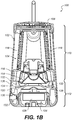
- FIGS. 1A and 1B are drawings showing a perspective view and a cross-sectional view, respectively, of a speaker system 100 that includes an outer housing 102 in the form of a substantially cylindrical sleeve, which houses an acoustic assembly 104, and a top cap 106 which seals off a top end of the housing 102 and provides a physical user interface 108.
- the housing 102 includes a plurality of perforations which allow acoustic energy from the acoustic assembly 104 to pass therethrough.
- the acoustic assembly 104 is made up of an acoustic sub-assembly 110 and a deflector sub-assembly 112.
- the acoustic sub-assembly 110 includes a single downward firing acoustic driver 114 secured to a vertical acoustic enclosure 116.
- a pair of passive radiators 118 are arranged on opposing side walls of the enclosure 116.
- the passive radiators 118 are configured to be driven by audio signals from an audio source (not shown) such that the passive radiators 118 are driven acoustically in phase with each other and mechanically out of phase with each other, to minimize vibration of the enclosure 116.
- the diaphragms of the passive radiators 118 are driven by pressure changes within the acoustic chamber resulting from operation of the acoustic driver 114.
- the deflector sub-assembly 112 includes an omni-directional acoustic deflector 120 and a bottom cap (a/k/a base 122), which are coupled together to form a compartment 124 that houses electronics, which power the speaker system 100.
- the electronics include a battery package 128, and a printed circuit board 130 that includes a plurality of electronic components mounted thereto.
- the electronic components 130 include, among other things, an amplifier chip and a battery charger chip.
- the battery package 128, however, may have a relatively low temperature limit. For example, in some cases, the battery package 128 has a temperature limit of about 52 degrees Celsius while charging and about 70 degree Celsius when not charging.
- the acoustic deflector 120 can be formed from a high thermal conductivity material.
- the omni-directional acoustic deflector 120 has four vertical legs 132 (a/k/a "mounting pillars") to which the enclosure 116 is mounted. Acoustic energy generated by the acoustic driver 114 propagates downward and is deflected into a nominal horizontal direction by an acoustically reflective body 134 of the acoustic deflector 120.
- Each opening 136 is defined by the enclosure 116, the acoustic deflector 120 and a pair of the vertical legs 132. These four openings 136 are acoustic apertures which pass the horizontally propagating acoustic energy. It should be understood that the propagation of the acoustic energy in a given direction includes a spreading of the propagating acoustic energy, for example, due to diffraction.
- the illustrated acoustic deflector 120 has a nominal truncated conical shape that is configured to be centered (i.e., coaxial) with respect to the motion axis of the acoustic driver 114.
- the slope of the conical outer surface between the base and vertex of the cone is not constant.
- the outer surface may have a non-linear slant profile such as a parabolic profile or a profile described by a truncated hyperboloid of revolution.
- the body of the acoustic deflector 120 is made of a thermally conductive material (e.g., a material having a thermal conductivity of at least 50 W/m-K), such as a metal.
- a thermally conductive material e.g., a material having a thermal conductivity of at least 50 W/m-K
- the body is formed of cast aluminum A380, which has a thermal conductivity of 96 W/m-K).
- an inner surface of the body 134 defines one or more projections 200 (one shown) for contacting, either directly or indirectly, one or more of the heat dissipating electronic components (e.g., the amplifier chip and/or the battery charger chip) such that heat is transferred from the electronic component(s) to the outer surface of the acoustically reflective body 134.
- the projection 200 is coupled to a first electronic component 202 via a thermal interface material (e.g., a thermally conductive pad 204).
- the thermally conductive pad 204 is formed of a compressible thermally conductive material. The use of a compressible material helps to accommodate dimensional tolerances to help eliminate air gaps.
- the thermal interface material is compressed between the first electronic component 202 and the acoustically reflective body 134 about 25% to about 75%.
- the thermally conductive pad 204 has a thermal conductivity of at least about 1 W/m-K, and, preferably, at least about 3 W/m-K. Suitable thermal pads are available from Parker Chomerics, Woburn, MA, under the trade name THERM-A-GAP TM Thermally Conductive Gap Filler Pads.
- Heat is conducted away from the electronic component(s) (e.g., the first electronic component 202) to the outer surface of the acoustically reflective body 134.
- the normal operation of the acoustic driver 114 provides an alternating (a/c) air flow along the outer surface which contributes to convective cooling of the acoustically reflective body 134. Through this convective and conductive heat transfer, sufficient heat is removed from the compartment 124 to provide suitable thermal conditions for the battery package 128.
- a plate 206 is mounted to the acoustically reflective body 134 (e.g., via thread forming screws) to form an acoustic cavity 208 therewith.
- a gasket material can be provided at the interface between the plate 206 and the acoustically reflective body 134 to help ensure an air tight seal.
- An opening 210 is provided in the top surface of the acoustically reflective body 134.
- the opening 210 extends into the acoustic cavity 208, thereby allowing acoustic energy from the acoustic driver 114 ( FIG. 1B ) to pass into the acoustic cavity 208.
- An acoustically absorbing material 212 is disposed in the opening. This acoustically absorbing material 212 attenuates the acoustic energy present near and at the peak of the lowest order circularly symmetric resonance mode.
- the diameter of the opening 210 is chosen so that the resulting attenuation of the acoustic energy propagating from the acoustic driver 114 ( FIG. 1B ) is limited to an acceptable level while achieving a desirable level of smoothing of the acoustic spectrum.
- the plate 206 includes a bump 214 that is arranged to accommodate placement of one or more relatively tall components (e.g., a capacitor 216) on the printed circuit board 130.
- the bump 214 also provides an irregular surface within the acoustic cavity 208. This irregular surface can further help to break up certain acoustic standing waves.
- the base 122 is a two shot molded plastic part and includes an inner bowl 218 that is molded from a polycarbonate (PC)/ABS; and an outer layer 220 formed of thermoplastic polyurethane (TPU).
- the base 122 provides the main support for the battery package 128 and printed circuit board 130.
- the printed circuit board 130 is secured to the battery package 128 (e.g., with screws) to form an electronic sub-assembly. That electronic sub-assembly is then secured to the base 122 (e.g., with screws).
- the base 122 is then secured to bosses 222 formed in the acoustically reflective body 134 with thread forming screws.
- the base 122 includes a tapered peripheral edge 224, which engages a mating tapered edge 226 on the acoustically reflective body 134 to form a watertight seal.
- the TPU outer layer 220 on the base 122 helps to provide for a very tight seal with the acoustic deflector 120. This seal is helpful to protect the electronics against moisture, but it also keeps the heat trapped in the compartment 124, so the conductive acoustic deflector 120 becomes an instrumental component to the thermal cooling design.
- the electronics 126 can be electrically connected to the acoustic driver 114 ( FIG. 1B ) and the user interface 108 ( FIG. 1A ) via wiring, which may pass through one or more apertures in the acoustically reflective body 134 and/or the acoustic enclosure 116.
- Grommets can be used to provide a seal between the wiring and the apertures.
Landscapes
- Engineering & Computer Science (AREA)
- Physics & Mathematics (AREA)
- Acoustics & Sound (AREA)
- Signal Processing (AREA)
- Health & Medical Sciences (AREA)
- Otolaryngology (AREA)
- Microelectronics & Electronic Packaging (AREA)
- Thermal Sciences (AREA)
- Cooling Or The Like Of Electrical Apparatus (AREA)
- Details Of Audible-Bandwidth Transducers (AREA)
- Obtaining Desirable Characteristics In Audible-Bandwidth Transducers (AREA)
Description
- This disclosure relates to an acoustic deflector that also serves as a heat sink for heat dissipating electronic components.
US 2016/337748 A1 shows an omni-directional acoustic deflector and respective loudspeaker system. - All examples and features mentioned below can be combined in any technically possible way. The present invention is defined by the independent claims, further embodiments are defined in the dependent claims.
- In one aspect, an omni-directional acoustic deflector includes an acoustically reflective body having a substantially conical outer surface, and an inner surface opposite the outer surface. The inner surface defines a region for contacting a first electronic component such that heat is transferred from the first electronic component to the outer surface of the acoustically reflective body.
- Implementations may include one of the following features, or a combination thereof as defined in the dependent claims.
- In some implementations, the acoustically reflective body is formed of a material having a thermal conductivity of 50 W/m-K or greater (e.g., 96 W/m-K).
- In certain implementations, the omni-directional acoustic deflector includes a plate that mounts to the acoustically reflective body to form an acoustic cavity therewith. The plate has an irregular surface.
- In some examples, the plate mounts to the acoustically reflective body so as to form an acoustic seal therewith.
- In certain examples, the irregular surface is arranged to accommodate a second electronic component.
- In some cases, the irregular surface includes a feature along a first side of the plate that extends into the acoustic cavity.
- In certain cases, the feature includes a bump that is arranged to accommodate placement of a second electronic component along a second side of the plate opposite the acoustic cavity.
- In some implementations, the substantially conical outer surface is configured to be disposed adjacent an acoustically radiating surface of an acoustic driver, and the acoustically reflective body has a truncated conical shape that includes a top surface that is configured to be centered with respect to a motion axis of the acoustic driver. The acoustically reflective body has an opening in the top surface that extends into the acoustic cavity enabling acoustic energy from the acoustic driver to pass into the acoustic cavity.
- In certain implementations, the inner surface of the acoustically reflective body defines a projection that includes the region for contacting the first electronic component.
- In another aspect, a speaker system includes an acoustic enclosure; an acoustic driver coupled to the acoustic enclosure; circuitry for powering the acoustic driver; and an omni-directional acoustic deflector. The omni-directional acoustic deflector includes an acoustically reflective body that has a substantially conical outer surface that is configured to be disposed adjacent an acoustically radiating surface of the acoustic driver, and an inner surface opposite the outer surface. The inner surface defines a region for contacting a first electronic component of the circuitry, such that heat is transferred from the first electronic component to the outer surface of the acoustically reflective body.
- In some implementations, the speaker system includes a base that is configured to be coupled to the omni-directional acoustic deflector to form a compartment therebetween.
- In certain implementations, the acoustically reflective body defines one or mounting posts for mounting the base to the omni-directional acoustic deflector.
- In some examples, the circuitry is disposed within the compartment.
- In certain examples, the speaker system includes a battery pack disposed within the compartment for powering the circuitry.
- In some cases, the base forms a watertight seal with the omni-directional acoustic deflector.
- In certain cases, the omni-directional acoustic deflector includes a peripheral edge with a first taper and the base includes a peripheral edge with a second taper that is configured to mate with the first taper to form the acoustic seal.
- In some implementations, the region is coupled to the first electronic component via a thermal interface material.
- In certain implementations, the thermal interface material has a thermal conductivity of at least 1 W/m-K (e.g., about 3 W/m-K).
- In some examples, the thermal interface material is compressed between the first electronic component and the acoustically reflective body about 25% to about 75%.
- In certain examples, the acoustic driver provides an alternating air flow along the outer surface of the omni-directional acoustic deflector which contributes to forced convective cooling.
- In some cases, the acoustic enclosure includes a pair of passive radiators configured to be driven by acoustic energy provided by the acoustic driver such that the passive radiators are driven acoustically in phase with each other and mechanically out of phase with each other, to minimize vibration of the acoustic enclosure.
- In certain cases, the acoustically reflective body comprises a leg for coupling the acoustically reflective body to the acoustic driver, such that the substantially conical outer surface is disposed adjacent to an acoustically radiating surface of the acoustic driver.
-
-
FIGS. 1A and1B are perspective and cross-sectional views, respectively, of a speaker system. -
FIG. 2 is a perspective view of an acoustic assembly from the speaker system ofFIG. 1A . -
FIG. 3 is a cross-sectional view of a deflector sub-assembly from the acoustic assembly ofFIG. 2 . - Multiple benefits are known for omni-directional speaker systems. These benefits include a more spacious sound image when the speaker system is placed near a boundary, such as a wall within a room, due to reflections. Another benefit is that the speaker system does not have to be oriented in a particular direction to achieve optimum high frequency coverage. This second advantage is highly desirable for mobile speaker systems where the speaker system and/or the listener may be moving.
- This disclosure is based on the realization that a passive acoustic component (e.g., an acoustic deflector) of such an omni-directional speaker system could also serve another purpose as a heat sink for conducting heat away from a heat producing electronic component packaged within the speaker system. An alternating (a/c) air flow that is produced via the normal operation of an acoustic driver can be used to provide forced convective cooling for the passive acoustic component, thereby to further enhance heat transfer away from the heat producing electronic component.
- In the examples described below, an acoustic deflector forms an upper wall of a sealed volume that contains electronics and a battery package (e.g., a lithium-ion battery). The electronics can include heat producing components, such as audio amplifiers and charge control circuitry for the battery package. This heat production can lead to undesirable thermal conditions in the sealed volume. Lithium-ion batteries, in particular, are subject to a limited operating range and therefore, heat is required to be efficiently transferred from the volume in order to improve the thermal conditions therein.
- By creating the acoustic deflector out of thermally conductive material, and placing the acoustic deflector in contact with the heat producing component(s), the conduction of heat out of the enclosure volume is improved. In addition, the deflector resides adjacent the acoustic driver which acts as a source of an alternating air flow that contributes to a cooling effect of the acoustic deflector.
-
FIGS. 1A and1B are drawings showing a perspective view and a cross-sectional view, respectively, of aspeaker system 100 that includes anouter housing 102 in the form of a substantially cylindrical sleeve, which houses anacoustic assembly 104, and atop cap 106 which seals off a top end of thehousing 102 and provides aphysical user interface 108. Thehousing 102 includes a plurality of perforations which allow acoustic energy from theacoustic assembly 104 to pass therethrough. - Referring to
FIGS. 1B and2 , theacoustic assembly 104 is made up of anacoustic sub-assembly 110 and adeflector sub-assembly 112. Theacoustic sub-assembly 110 includes a single downward firingacoustic driver 114 secured to a verticalacoustic enclosure 116. A pair ofpassive radiators 118 are arranged on opposing side walls of theenclosure 116. Thepassive radiators 118 are configured to be driven by audio signals from an audio source (not shown) such that thepassive radiators 118 are driven acoustically in phase with each other and mechanically out of phase with each other, to minimize vibration of theenclosure 116. - The volume within the region above the
acoustic driver 114 and inside theenclosure 116, as "sealed" with thepassive radiators 118, defines an acoustic chamber. The diaphragms of thepassive radiators 118 are driven by pressure changes within the acoustic chamber resulting from operation of theacoustic driver 114. - The
deflector sub-assembly 112 includes an omni-directionalacoustic deflector 120 and a bottom cap (a/k/a base 122), which are coupled together to form acompartment 124 that houses electronics, which power thespeaker system 100. The electronics include abattery package 128, and a printedcircuit board 130 that includes a plurality of electronic components mounted thereto. Theelectronic components 130 include, among other things, an amplifier chip and a battery charger chip. Thebattery package 128, however, may have a relatively low temperature limit. For example, in some cases, thebattery package 128 has a temperature limit of about 52 degrees Celsius while charging and about 70 degree Celsius when not charging. As discussed below, to assist heat transfer out of thecompartment 124 to provide for more suitable thermal conditions for thebattery package 128, theacoustic deflector 120 can be formed from a high thermal conductivity material. - The omni-directional
acoustic deflector 120 has four vertical legs 132 (a/k/a "mounting pillars") to which theenclosure 116 is mounted. Acoustic energy generated by theacoustic driver 114 propagates downward and is deflected into a nominal horizontal direction by an acousticallyreflective body 134 of theacoustic deflector 120. - There are four substantially
rectangular openings 136. Eachopening 136 is defined by theenclosure 116, theacoustic deflector 120 and a pair of thevertical legs 132. These fouropenings 136 are acoustic apertures which pass the horizontally propagating acoustic energy. It should be understood that the propagation of the acoustic energy in a given direction includes a spreading of the propagating acoustic energy, for example, due to diffraction. - The illustrated
acoustic deflector 120 has a nominal truncated conical shape that is configured to be centered (i.e., coaxial) with respect to the motion axis of theacoustic driver 114. In other examples, the slope of the conical outer surface between the base and vertex of the cone (a/k/a "cone axis") is not constant. For example, the outer surface may have a non-linear slant profile such as a parabolic profile or a profile described by a truncated hyperboloid of revolution. Notably, the body of theacoustic deflector 120 is made of a thermally conductive material (e.g., a material having a thermal conductivity of at least 50 W/m-K), such as a metal. In some cases, the body is formed of cast aluminum A380, which has a thermal conductivity of 96 W/m-K). - Referring to
FIG. 3 , an inner surface of thebody 134 defines one or more projections 200 (one shown) for contacting, either directly or indirectly, one or more of the heat dissipating electronic components (e.g., the amplifier chip and/or the battery charger chip) such that heat is transferred from the electronic component(s) to the outer surface of the acousticallyreflective body 134. In the illustrated implementation, theprojection 200 is coupled to a firstelectronic component 202 via a thermal interface material (e.g., a thermally conductive pad 204). In some cases, the thermallyconductive pad 204 is formed of a compressible thermally conductive material. The use of a compressible material helps to accommodate dimensional tolerances to help eliminate air gaps. In some cases, the thermal interface material is compressed between the firstelectronic component 202 and the acousticallyreflective body 134 about 25% to about 75%. Preferably, the thermallyconductive pad 204 has a thermal conductivity of at least about 1 W/m-K, and, preferably, at least about 3 W/m-K. Suitable thermal pads are available from Parker Chomerics, Woburn, MA, under the trade name THERM-A-GAP™ Thermally Conductive Gap Filler Pads. - Heat is conducted away from the electronic component(s) (e.g., the first electronic component 202) to the outer surface of the acoustically
reflective body 134. The normal operation of theacoustic driver 114 provides an alternating (a/c) air flow along the outer surface which contributes to convective cooling of the acousticallyreflective body 134. Through this convective and conductive heat transfer, sufficient heat is removed from thecompartment 124 to provide suitable thermal conditions for thebattery package 128. - Referring still to
FIG. 3 , aplate 206 is mounted to the acoustically reflective body 134 (e.g., via thread forming screws) to form anacoustic cavity 208 therewith. A gasket material can be provided at the interface between theplate 206 and the acousticallyreflective body 134 to help ensure an air tight seal. - An
opening 210 is provided in the top surface of the acousticallyreflective body 134. Theopening 210 extends into theacoustic cavity 208, thereby allowing acoustic energy from the acoustic driver 114 (FIG. 1B ) to pass into theacoustic cavity 208. An acoustically absorbingmaterial 212 is disposed in the opening. This acousticallyabsorbing material 212 attenuates the acoustic energy present near and at the peak of the lowest order circularly symmetric resonance mode. In some implementations, the diameter of theopening 210 is chosen so that the resulting attenuation of the acoustic energy propagating from the acoustic driver 114 (FIG. 1B ) is limited to an acceptable level while achieving a desirable level of smoothing of the acoustic spectrum. - Notably, the
plate 206 includes abump 214 that is arranged to accommodate placement of one or more relatively tall components (e.g., a capacitor 216) on the printedcircuit board 130. Thebump 214 also provides an irregular surface within theacoustic cavity 208. This irregular surface can further help to break up certain acoustic standing waves. - In some implementations, the
base 122 is a two shot molded plastic part and includes aninner bowl 218 that is molded from a polycarbonate (PC)/ABS; and anouter layer 220 formed of thermoplastic polyurethane (TPU). Thebase 122 provides the main support for thebattery package 128 and printedcircuit board 130. In that regard, the printedcircuit board 130 is secured to the battery package 128 (e.g., with screws) to form an electronic sub-assembly. That electronic sub-assembly is then secured to the base 122 (e.g., with screws). Thebase 122 is then secured tobosses 222 formed in the acousticallyreflective body 134 with thread forming screws. Thebase 122 includes a taperedperipheral edge 224, which engages a mating taperededge 226 on the acousticallyreflective body 134 to form a watertight seal. The TPUouter layer 220 on thebase 122 helps to provide for a very tight seal with theacoustic deflector 120. This seal is helpful to protect the electronics against moisture, but it also keeps the heat trapped in thecompartment 124, so the conductiveacoustic deflector 120 becomes an instrumental component to the thermal cooling design. - The electronics 126 can be electrically connected to the acoustic driver 114 (
FIG. 1B ) and the user interface 108 (FIG. 1A ) via wiring, which may pass through one or more apertures in the acousticallyreflective body 134 and/or theacoustic enclosure 116. Grommets can be used to provide a seal between the wiring and the apertures. - A number of implementations have been described. Nevertheless, it will be understood that additional modifications may be made without departing from the scope of the following claims.
Claims (15)
- An omni-directional acoustic deflector (120) comprising:an acoustically reflective body (134) having a substantially conical outer surface, and an inner surface opposite the outer surface,characterized in that the inner surface defines a region for contacting a first electronic component (202) such that heat is transferred from the first electronic component to the outer surface of the acoustically reflective body.
- The omni-directional acoustic deflector (120) of claim 1, wherein the acoustically reflective body is formed of a material having a thermal conductivity of 50 W/m-k or greater.
- The omni-directional acoustic deflector (120) of claim 1, further comprising a plate (206) that mounts to the acoustically reflective body to form an acoustic cavity (208) therewith, the plate including a bump (214) so as to have an irregular surface.
- The omni-directional acoustic deflector (120) of claim 3, wherein the plate mounts to the acoustically reflective body so as to form an acoustic seal therewith.
- The omni-directional acoustic deflector (120) of claim 3, wherein the bump is arranged to accommodate placement of a second electronic component (216).
- The omni-directional acoustic deflector (120) of claim 3, wherein the substantially conical outer surface is configured to be disposed adjacent an acoustically radiating surface of an acoustic driver (114), and wherein the acoustically reflective body has a truncated conical shape comprising a top surface that is configured to be centered with respect to a motion axis of the acoustic driver, the acoustically reflective body having an opening in the top surface that extends into the acoustic cavity enabling acoustic energy from the acoustic driver to pass into the acoustic cavity.
- The omni-directional acoustic deflector (120) of claim 1, wherein the inner surface of the acoustically reflective body defines a projection (200) that includes the region for contacting the first electronic component.
- The omni-directional acoustic deflector (120) of claim 7, wherein the projection is arranged for contacting the first electronic component directly.
- The omni-directional acoustic deflector (120) of claim 7, wherein the projection is arranged for contacting the first electronic component indirectly via a thermally conductive pad (204).
- A speaker system (100) comprising:an acoustic enclosure (116);an acoustic driver (114) coupled to the acoustic enclosure;circuitry for powering the acoustic driver, the circuitry comprising a first electronic component (202); andan omni-directional acoustic deflector (120) comprising an acoustically reflective body having a substantially conical outer surface configured to be disposed adjacent an acoustically radiating surface of the acoustic driver, and an inner surface opposite the outer surface,characterized in that the inner surface defines a region for contacting the first electronic component, such that heat is transferred from the first electronic component to the outer surface of the acoustically reflective body.
- The speaker system (100) of claim 10, further comprising a base (122) configured to be coupled to the omni-directional acoustic deflector to form a compartment (124) therebetween.
- The speaker system (100) of claim 11, wherein the acoustically reflective body defines one or mounting posts for mounting the base to the omni-directional acoustic deflector.
- The speaker system (100) of claim 11, wherein the circuitry is disposed within the compartment.
- The speaker system (100) of claim 11, further comprising a battery pack (128) disposed within the compartment for powering the circuitry.
- The speaker system (100) of claim 11, wherein the base forms a watertight seal with the omni-directional acoustic deflector.
Applications Claiming Priority (2)
| Application Number | Priority Date | Filing Date | Title |
|---|---|---|---|
| US15/475,542 US10306356B2 (en) | 2017-03-31 | 2017-03-31 | Acoustic deflector as heat sink |
| PCT/US2018/025477 WO2018183898A1 (en) | 2017-03-31 | 2018-03-30 | Omni-directional acoustic deflector as heat sink |
Publications (2)
| Publication Number | Publication Date |
|---|---|
| EP3603104A1 EP3603104A1 (en) | 2020-02-05 |
| EP3603104B1 true EP3603104B1 (en) | 2021-12-08 |
Family
ID=62063191
Family Applications (1)
| Application Number | Title | Priority Date | Filing Date |
|---|---|---|---|
| EP18720456.5A Active EP3603104B1 (en) | 2017-03-31 | 2018-03-30 | Omni-directional acoustic deflector as heat sink |
Country Status (5)
| Country | Link |
|---|---|
| US (2) | US10306356B2 (en) |
| EP (1) | EP3603104B1 (en) |
| JP (1) | JP6918132B2 (en) |
| CN (1) | CN110692254B (en) |
| WO (1) | WO2018183898A1 (en) |
Families Citing this family (23)
| Publication number | Priority date | Publication date | Assignee | Title |
|---|---|---|---|---|
| USD837762S1 (en) | 2016-12-29 | 2019-01-08 | Harman International Industries, Incorporated | Loudspeaker cover |
| USD878333S1 (en) * | 2017-12-21 | 2020-03-17 | Harman International Industries, Incorporated | Loudspeaker |
| JP7072186B2 (en) * | 2018-02-08 | 2022-05-20 | 株式会社オーディオテクニカ | Microphone device and case for microphone device |
| WO2020060577A1 (en) | 2018-09-18 | 2020-03-26 | Google Llc | Display assistant device |
| KR102613661B1 (en) * | 2018-08-06 | 2023-12-14 | 삼성전자주식회사 | Electronic device with heat radiating structure |
| CN111316193B (en) | 2018-09-18 | 2023-09-15 | 谷歌有限责任公司 | display assistant device |
| US10880628B2 (en) | 2018-12-14 | 2020-12-29 | Bose Corporation | Audio device with sealing member and internal heat sink |
| CN111586537B (en) * | 2019-02-19 | 2021-08-24 | 纬创资通股份有限公司 | Loudspeaker with replaceable sound guide assembly |
| CN114270872B (en) * | 2019-06-26 | 2023-11-17 | 歌尔股份有限公司 | Acoustic reflector and acoustic electronic device |
| US11368770B2 (en) * | 2019-07-22 | 2022-06-21 | AAC Technologies Pte. Ltd. | Speaker box device and mobile terminal using same |
| US11375301B2 (en) * | 2019-07-22 | 2022-06-28 | AAC Technologies Pte. Ltd. | Speaker box device and mobile terminal using same |
| US11375302B2 (en) * | 2019-07-22 | 2022-06-28 | AAC Technologies Pte. Ltd. | Speaker device and mobile terminal provided with speaker device |
| US11277678B2 (en) * | 2019-11-21 | 2022-03-15 | Bose Corporation | Handle assembly for electronic device |
| CN113473307B (en) * | 2020-03-31 | 2025-08-12 | 中强光电股份有限公司 | Speaker structure and intelligent robot |
| US11310585B2 (en) | 2020-09-03 | 2022-04-19 | Apple Inc. | Compact speaker |
| US11206470B1 (en) | 2020-09-03 | 2021-12-21 | Apple Inc. | Electronic speaker with a planar foot |
| JP7666973B2 (en) | 2021-04-13 | 2025-04-22 | アルプスアルパイン株式会社 | Speaker |
| USD1026846S1 (en) * | 2021-06-30 | 2024-05-14 | Ricoh Company, Ltd. | Microphone speaker |
| JP1708966S (en) * | 2021-06-30 | 2022-03-04 | Microphone speaker with camera | |
| US12413901B2 (en) * | 2021-12-24 | 2025-09-09 | Canon Denshi Kabushiki Kaisha | High-performance and flexible loudspeaker apparatus usable in various scenes |
| CN216775009U (en) * | 2021-12-30 | 2022-06-17 | 昆山联滔电子有限公司 | Loudspeaker |
| USD985533S1 (en) * | 2022-05-17 | 2023-05-09 | Weibin Tian | Bluetooth audio |
| JP7663686B2 (en) * | 2022-12-19 | 2025-04-16 | エーエーシー テクノロジーズ (ナンジン) カンパニーリミテッド | Integrated speaker and mobile terminal |
Family Cites Families (71)
| Publication number | Priority date | Publication date | Assignee | Title |
|---|---|---|---|---|
| US3778551A (en) * | 1969-01-17 | 1973-12-11 | Chicago Musical Instr Co | Air cooled audio amplifier assembly |
| US3892917A (en) | 1971-10-07 | 1975-07-01 | Nippon Musical Instruments Mfg | Speaker system for multichannel stereosignal reproduction |
| US3912866A (en) | 1974-01-30 | 1975-10-14 | Showsound Inc | Folded bass horn speaker |
| IT1086464B (en) | 1977-09-06 | 1985-05-28 | Selmin Sas | METHOD AND DEVICES FOR OMNIDIRECTIONAL IRRADIATION OF SOUND WAVES |
| US4348549A (en) | 1978-02-06 | 1982-09-07 | Emmanuel Berlant | Loudspeaker system |
| US4625328A (en) * | 1983-06-13 | 1986-11-25 | Konutra Industries, Ltd. | Integrated amplifier and speaker system with improved cooling efficiency |
| US4620317A (en) | 1984-04-05 | 1986-10-28 | Shure Brothers, Inc. | Tabletop speaker assembly |
| JPS61219289A (en) | 1985-03-25 | 1986-09-29 | Matsushita Electric Ind Co Ltd | Speaker system with amplifier |
| JPS61264897A (en) | 1985-05-20 | 1986-11-22 | Mitsubishi Electric Corp | Speaker device |
| JPS61264896A (en) | 1985-05-20 | 1986-11-22 | Mitsubishi Electric Corp | Reflection type speaker system |
| US5115882A (en) | 1989-03-29 | 1992-05-26 | Woody D Grier | Omnidirectional dispersion system for multiway loudspeakers |
| US5097513A (en) * | 1990-05-31 | 1992-03-17 | Southern Audio Services, Inc. | Speaker system enclosure integrated with amplifier circuit board |
| US5418336A (en) * | 1990-10-17 | 1995-05-23 | Canon Research Centre Europe Ltd. | Sound output device |
| US5268538A (en) | 1991-06-12 | 1993-12-07 | Sonic Systems, Inc. | Hemispherically wide-radiating-angle loudspeaker system |
| IT1264323B (en) * | 1992-07-31 | 1996-09-23 | Loudspeaker enclosure for low frequencies with forced amplifier cooling system | |
| US5533132A (en) * | 1995-01-23 | 1996-07-02 | Jbl Incorporated | Loudspeaker thermal management structure |
| US5533152A (en) * | 1995-05-02 | 1996-07-02 | Eastman Kodak Company | Method and apparatus for coupling light emitted from a multi-mode laser diode array to a multi-mode optical fiber |
| US6257365B1 (en) | 1996-08-30 | 2001-07-10 | Mediaphile Av Technologies, Inc. | Cone reflector/coupler speaker system and method |
| DE19716315C2 (en) | 1997-04-18 | 2002-06-13 | Heinz Juergen Augustin | Omnidirectional loudspeaker system |
| WO1999003375A1 (en) * | 1997-07-18 | 1999-01-28 | Mackie Designs Inc. | Passive radiator cooled electronics/heat sink housing for a powered speaker |
| CN1247045C (en) | 1997-10-10 | 2006-03-22 | 三星电子株式会社 | Universal loadspeaker system |
| US20020057811A1 (en) * | 1998-08-13 | 2002-05-16 | Winslow Scott Burleson | Apparatus using cooling spaces as speaker chambers |
| US6430297B1 (en) * | 1998-09-28 | 2002-08-06 | Murata Manufacturing Co., Ltd. | Speaker and speaker device |
| US6026928A (en) | 1999-04-06 | 2000-02-22 | Maharaj; Ashok A. | Apparatus and method for reduced distortion loudspeakers |
| US6597797B1 (en) | 1999-06-23 | 2003-07-22 | Sonic Systems, Inc. | Spherical loudspeaker system with enhanced performance |
| US6496373B1 (en) * | 1999-11-04 | 2002-12-17 | Amerasia International Technology, Inc. | Compressible thermally-conductive interface |
| US6578660B2 (en) | 2000-06-21 | 2003-06-17 | Ronald K. Taylor | Speaker enclosure venturi expander |
| US6957715B2 (en) | 2002-01-25 | 2005-10-25 | Carl Christiansen | Garden speaker |
| USD476310S1 (en) | 2002-06-20 | 2003-06-24 | Sony Corporation | Speaker box |
| USD476311S1 (en) | 2002-06-20 | 2003-06-24 | Sony Corporation | Speaker box |
| KR100526599B1 (en) * | 2003-04-01 | 2005-11-08 | 삼성전자주식회사 | Speaker |
| JP2005057088A (en) * | 2003-08-05 | 2005-03-03 | Agilent Technol Inc | Multi-layered heat conduction member and electronic device using the same |
| US7463744B2 (en) | 2003-10-31 | 2008-12-09 | Bose Corporation | Porting |
| US7181039B2 (en) * | 2004-01-30 | 2007-02-20 | Step Technologies Inc. | Thermal chimney equipped audio speaker cabinet |
| US6944024B1 (en) * | 2004-02-19 | 2005-09-13 | Audioplex Technology Incorporated | Heat sink bracket for powered loudspeaker |
| USD508042S1 (en) | 2004-05-21 | 2005-08-02 | Sony Corporation | Speaker box |
| US7421954B2 (en) * | 2004-06-18 | 2008-09-09 | Bose Corporation | Active suspension controller |
| USD521979S1 (en) | 2005-02-08 | 2006-05-30 | Sony Corporation | Speaker box |
| US7349207B2 (en) * | 2005-09-08 | 2008-03-25 | Brookstone Purchasing, Inc. | Heat dissipating audio systems and methods thereof |
| USD545299S1 (en) | 2005-12-08 | 2007-06-26 | Sony Corporation | Speaker box |
| USD581397S1 (en) | 2006-11-30 | 2008-11-25 | Sony Corporation | Speaker box |
| USD581398S1 (en) | 2006-11-30 | 2008-11-25 | Sony Corporation | Speaker box |
| US20080192972A1 (en) | 2007-02-13 | 2008-08-14 | Vernon Lewallen | Phasing plug for acoustic compression drivers |
| JP2009141657A (en) | 2007-12-06 | 2009-06-25 | Pioneer Electronic Corp | Speaker apparatus |
| USD591266S1 (en) | 2008-01-14 | 2009-04-28 | Sony Corporation | Speaker box |
| US8189841B2 (en) | 2008-03-27 | 2012-05-29 | Bose Corporation | Acoustic passive radiating |
| US8130994B2 (en) | 2008-06-17 | 2012-03-06 | Harman International Industries, Incorporated | Waveguide |
| USD600287S1 (en) | 2008-07-24 | 2009-09-15 | Sony Computer Entertainment Inc. | Base station box |
| KR101192910B1 (en) | 2008-08-14 | 2012-10-18 | 하만인터내셔날인더스트리스인코포레이티드 | Phase plug and acoustic lens for direct radiating loudspeaker |
| JP2010093767A (en) | 2008-10-07 | 2010-04-22 | Junichi Kakumoto | Loudspeaker system |
| US8126180B2 (en) * | 2008-10-31 | 2012-02-28 | Bose Corporation | Dual configuration speaker |
| US8467557B2 (en) | 2009-09-24 | 2013-06-18 | MS Electronics LLC | Coaxial speaker system with improved transition between individual speakers |
| SG170641A1 (en) | 2009-10-30 | 2011-05-30 | Dream Infotainment Resources Pte Ltd | Omnidirectional speaker |
| US8290195B2 (en) | 2010-03-31 | 2012-10-16 | Bose Corporation | Acoustic radiation pattern adjusting |
| DE102010021879A1 (en) | 2010-05-28 | 2011-12-01 | Frank Held | Loudspeaker device with circumferential, funnel-shaped sound outlet opening |
| US8442242B2 (en) | 2010-09-23 | 2013-05-14 | Ronald Paul Harwood | Acoustic reflector |
| USD646665S1 (en) | 2010-12-28 | 2011-10-11 | Sony Corporation | Speaker box |
| DE102011016326B4 (en) | 2011-04-01 | 2016-12-15 | Kerstin Brachaus-Mechow | Speaker layout |
| US8837763B1 (en) * | 2011-06-21 | 2014-09-16 | Cue Acoustics, Inc. | Inertially balanced miniature low frequency speaker system |
| US8561756B2 (en) * | 2012-02-17 | 2013-10-22 | Bose Corporation | Acoustic ports aligned to create free convective airflow |
| US8798308B2 (en) * | 2012-02-21 | 2014-08-05 | Bose Corporation | Convective airflow using a passive radiator |
| US9282388B2 (en) | 2012-04-26 | 2016-03-08 | Adam Stephen Wegener | Sound system using repurposed materials |
| SG2013094784A (en) | 2013-12-20 | 2015-07-30 | Dream Audiolab Pte Ltd | Improved omnidirectional speaker with soundwave deflectors |
| CN103873991A (en) * | 2014-02-26 | 2014-06-18 | 谭红梅 | A method and device for extending the frequency response range of a loudspeaker driver |
| US9282398B2 (en) | 2014-03-19 | 2016-03-08 | Dana Monroe | Speaker system having wide bandwidth and wide high-frequency dispersion |
| US10045461B1 (en) * | 2014-09-30 | 2018-08-07 | Apple Inc. | Electronic device with diaphragm cooling |
| US9544681B2 (en) | 2015-01-31 | 2017-01-10 | Bose Corporation | Acoustic deflector for omni-directional speaker system |
| US9883282B2 (en) | 2015-01-31 | 2018-01-30 | Bose Corporation | Acoustic deflector for omni-directional speaker system |
| GB201503426D0 (en) * | 2015-02-27 | 2015-04-15 | Native Design Ltd | Light and speaker driver device |
| US9736560B2 (en) * | 2015-09-14 | 2017-08-15 | Logitech Europe S.A. | Liquid impermeable sealed speaker design |
| US10034081B2 (en) | 2015-09-28 | 2018-07-24 | Samsung Electronics Co., Ltd. | Acoustic filter for omnidirectional loudspeaker |
-
2017
- 2017-03-31 US US15/475,542 patent/US10306356B2/en active Active
-
2018
- 2018-03-30 JP JP2019553373A patent/JP6918132B2/en active Active
- 2018-03-30 WO PCT/US2018/025477 patent/WO2018183898A1/en not_active Ceased
- 2018-03-30 EP EP18720456.5A patent/EP3603104B1/en active Active
- 2018-03-30 CN CN201880035984.3A patent/CN110692254B/en active Active
-
2019
- 2019-05-22 US US16/419,557 patent/US10887684B2/en active Active
Also Published As
| Publication number | Publication date |
|---|---|
| US20190273985A1 (en) | 2019-09-05 |
| US10306356B2 (en) | 2019-05-28 |
| US20180288525A1 (en) | 2018-10-04 |
| WO2018183898A1 (en) | 2018-10-04 |
| EP3603104A1 (en) | 2020-02-05 |
| JP6918132B2 (en) | 2021-08-11 |
| JP2020513175A (en) | 2020-04-30 |
| CN110692254A (en) | 2020-01-14 |
| US10887684B2 (en) | 2021-01-05 |
| CN110692254B (en) | 2021-04-16 |
Similar Documents
| Publication | Publication Date | Title |
|---|---|---|
| US10887684B2 (en) | Acoustic deflector as heat sink | |
| CN107343247B (en) | Loudspeaker box | |
| US20160295316A1 (en) | Loudspeaker module | |
| WO2016015574A1 (en) | Electrical appliance box, domestic electrical appliance and air-conditioner having easily combustible and easily inflammable refrigerant | |
| US20180213319A1 (en) | Sound Generator | |
| CN105453585A (en) | Portable loudspeaker | |
| US5097513A (en) | Speaker system enclosure integrated with amplifier circuit board | |
| CN206341416U (en) | Loudspeaker module | |
| CN110996234A (en) | Speaker module and electronic equipment | |
| US11375302B2 (en) | Speaker device and mobile terminal provided with speaker device | |
| CN210093444U (en) | Speaker device and mobile terminal having the same | |
| CN110996230A (en) | Speaker module and electronic equipment | |
| CN114466294B (en) | Speakers and Electronics | |
| CN208675540U (en) | MEMS microphone | |
| US20210029457A1 (en) | Speaker Box and Mobile Terminal | |
| US20210029458A1 (en) | Speaker Device and Mobile Terminal | |
| CN111010634B (en) | Speaker module and electronic equipment | |
| CN103347234B (en) | Woofer and thereafter operatic tunes forming method | |
| CN112291645A (en) | Speaker device and mobile terminal | |
| CN210986331U (en) | Speaker box device and mobile terminal | |
| CN210093534U (en) | Loudspeaker box and mobile terminal | |
| CN220402122U (en) | Transceiver assembly and housing thereof | |
| CN212115579U (en) | Loudspeaker module | |
| CN216960056U (en) | Set-top box and audio-visual system | |
| CN111683323B (en) | Earphone set |
Legal Events
| Date | Code | Title | Description |
|---|---|---|---|
| STAA | Information on the status of an ep patent application or granted ep patent |
Free format text: STATUS: UNKNOWN |
|
| STAA | Information on the status of an ep patent application or granted ep patent |
Free format text: STATUS: THE INTERNATIONAL PUBLICATION HAS BEEN MADE |
|
| PUAI | Public reference made under article 153(3) epc to a published international application that has entered the european phase |
Free format text: ORIGINAL CODE: 0009012 |
|
| STAA | Information on the status of an ep patent application or granted ep patent |
Free format text: STATUS: REQUEST FOR EXAMINATION WAS MADE |
|
| 17P | Request for examination filed |
Effective date: 20191001 |
|
| AK | Designated contracting states |
Kind code of ref document: A1 Designated state(s): AL AT BE BG CH CY CZ DE DK EE ES FI FR GB GR HR HU IE IS IT LI LT LU LV MC MK MT NL NO PL PT RO RS SE SI SK SM TR |
|
| AX | Request for extension of the european patent |
Extension state: BA ME |
|
| DAV | Request for validation of the european patent (deleted) | ||
| DAX | Request for extension of the european patent (deleted) | ||
| GRAP | Despatch of communication of intention to grant a patent |
Free format text: ORIGINAL CODE: EPIDOSNIGR1 |
|
| STAA | Information on the status of an ep patent application or granted ep patent |
Free format text: STATUS: GRANT OF PATENT IS INTENDED |
|
| INTG | Intention to grant announced |
Effective date: 20210924 |
|
| GRAS | Grant fee paid |
Free format text: ORIGINAL CODE: EPIDOSNIGR3 |
|
| GRAA | (expected) grant |
Free format text: ORIGINAL CODE: 0009210 |
|
| STAA | Information on the status of an ep patent application or granted ep patent |
Free format text: STATUS: THE PATENT HAS BEEN GRANTED |
|
| AK | Designated contracting states |
Kind code of ref document: B1 Designated state(s): AL AT BE BG CH CY CZ DE DK EE ES FI FR GB GR HR HU IE IS IT LI LT LU LV MC MK MT NL NO PL PT RO RS SE SI SK SM TR |
|
| REG | Reference to a national code |
Ref country code: GB Ref legal event code: FG4D |
|
| REG | Reference to a national code |
Ref country code: AT Ref legal event code: REF Ref document number: 1454659 Country of ref document: AT Kind code of ref document: T Effective date: 20211215 Ref country code: CH Ref legal event code: EP |
|
| REG | Reference to a national code |
Ref country code: DE Ref legal event code: R096 Ref document number: 602018027859 Country of ref document: DE |
|
| REG | Reference to a national code |
Ref country code: IE Ref legal event code: FG4D |
|
| REG | Reference to a national code |
Ref country code: LT Ref legal event code: MG9D |
|
| REG | Reference to a national code |
Ref country code: NL Ref legal event code: MP Effective date: 20211208 |
|
| PG25 | Lapsed in a contracting state [announced via postgrant information from national office to epo] |
Ref country code: RS Free format text: LAPSE BECAUSE OF FAILURE TO SUBMIT A TRANSLATION OF THE DESCRIPTION OR TO PAY THE FEE WITHIN THE PRESCRIBED TIME-LIMIT Effective date: 20211208 Ref country code: LT Free format text: LAPSE BECAUSE OF FAILURE TO SUBMIT A TRANSLATION OF THE DESCRIPTION OR TO PAY THE FEE WITHIN THE PRESCRIBED TIME-LIMIT Effective date: 20211208 Ref country code: FI Free format text: LAPSE BECAUSE OF FAILURE TO SUBMIT A TRANSLATION OF THE DESCRIPTION OR TO PAY THE FEE WITHIN THE PRESCRIBED TIME-LIMIT Effective date: 20211208 Ref country code: BG Free format text: LAPSE BECAUSE OF FAILURE TO SUBMIT A TRANSLATION OF THE DESCRIPTION OR TO PAY THE FEE WITHIN THE PRESCRIBED TIME-LIMIT Effective date: 20220308 |
|
| REG | Reference to a national code |
Ref country code: AT Ref legal event code: MK05 Ref document number: 1454659 Country of ref document: AT Kind code of ref document: T Effective date: 20211208 |
|
| PG25 | Lapsed in a contracting state [announced via postgrant information from national office to epo] |
Ref country code: SE Free format text: LAPSE BECAUSE OF FAILURE TO SUBMIT A TRANSLATION OF THE DESCRIPTION OR TO PAY THE FEE WITHIN THE PRESCRIBED TIME-LIMIT Effective date: 20211208 Ref country code: NO Free format text: LAPSE BECAUSE OF FAILURE TO SUBMIT A TRANSLATION OF THE DESCRIPTION OR TO PAY THE FEE WITHIN THE PRESCRIBED TIME-LIMIT Effective date: 20220308 Ref country code: LV Free format text: LAPSE BECAUSE OF FAILURE TO SUBMIT A TRANSLATION OF THE DESCRIPTION OR TO PAY THE FEE WITHIN THE PRESCRIBED TIME-LIMIT Effective date: 20211208 Ref country code: HR Free format text: LAPSE BECAUSE OF FAILURE TO SUBMIT A TRANSLATION OF THE DESCRIPTION OR TO PAY THE FEE WITHIN THE PRESCRIBED TIME-LIMIT Effective date: 20211208 Ref country code: GR Free format text: LAPSE BECAUSE OF FAILURE TO SUBMIT A TRANSLATION OF THE DESCRIPTION OR TO PAY THE FEE WITHIN THE PRESCRIBED TIME-LIMIT Effective date: 20220309 Ref country code: ES Free format text: LAPSE BECAUSE OF FAILURE TO SUBMIT A TRANSLATION OF THE DESCRIPTION OR TO PAY THE FEE WITHIN THE PRESCRIBED TIME-LIMIT Effective date: 20211208 |
|
| PG25 | Lapsed in a contracting state [announced via postgrant information from national office to epo] |
Ref country code: NL Free format text: LAPSE BECAUSE OF FAILURE TO SUBMIT A TRANSLATION OF THE DESCRIPTION OR TO PAY THE FEE WITHIN THE PRESCRIBED TIME-LIMIT Effective date: 20211208 |
|
| PG25 | Lapsed in a contracting state [announced via postgrant information from national office to epo] |
Ref country code: SM Free format text: LAPSE BECAUSE OF FAILURE TO SUBMIT A TRANSLATION OF THE DESCRIPTION OR TO PAY THE FEE WITHIN THE PRESCRIBED TIME-LIMIT Effective date: 20211208 Ref country code: SK Free format text: LAPSE BECAUSE OF FAILURE TO SUBMIT A TRANSLATION OF THE DESCRIPTION OR TO PAY THE FEE WITHIN THE PRESCRIBED TIME-LIMIT Effective date: 20211208 Ref country code: RO Free format text: LAPSE BECAUSE OF FAILURE TO SUBMIT A TRANSLATION OF THE DESCRIPTION OR TO PAY THE FEE WITHIN THE PRESCRIBED TIME-LIMIT Effective date: 20211208 Ref country code: PT Free format text: LAPSE BECAUSE OF FAILURE TO SUBMIT A TRANSLATION OF THE DESCRIPTION OR TO PAY THE FEE WITHIN THE PRESCRIBED TIME-LIMIT Effective date: 20220408 Ref country code: EE Free format text: LAPSE BECAUSE OF FAILURE TO SUBMIT A TRANSLATION OF THE DESCRIPTION OR TO PAY THE FEE WITHIN THE PRESCRIBED TIME-LIMIT Effective date: 20211208 Ref country code: CZ Free format text: LAPSE BECAUSE OF FAILURE TO SUBMIT A TRANSLATION OF THE DESCRIPTION OR TO PAY THE FEE WITHIN THE PRESCRIBED TIME-LIMIT Effective date: 20211208 |
|
| PG25 | Lapsed in a contracting state [announced via postgrant information from national office to epo] |
Ref country code: PL Free format text: LAPSE BECAUSE OF FAILURE TO SUBMIT A TRANSLATION OF THE DESCRIPTION OR TO PAY THE FEE WITHIN THE PRESCRIBED TIME-LIMIT Effective date: 20211208 Ref country code: AT Free format text: LAPSE BECAUSE OF FAILURE TO SUBMIT A TRANSLATION OF THE DESCRIPTION OR TO PAY THE FEE WITHIN THE PRESCRIBED TIME-LIMIT Effective date: 20211208 |
|
| REG | Reference to a national code |
Ref country code: DE Ref legal event code: R097 Ref document number: 602018027859 Country of ref document: DE |
|
| PG25 | Lapsed in a contracting state [announced via postgrant information from national office to epo] |
Ref country code: IS Free format text: LAPSE BECAUSE OF FAILURE TO SUBMIT A TRANSLATION OF THE DESCRIPTION OR TO PAY THE FEE WITHIN THE PRESCRIBED TIME-LIMIT Effective date: 20220408 |
|
| PLBE | No opposition filed within time limit |
Free format text: ORIGINAL CODE: 0009261 |
|
| STAA | Information on the status of an ep patent application or granted ep patent |
Free format text: STATUS: NO OPPOSITION FILED WITHIN TIME LIMIT |
|
| PG25 | Lapsed in a contracting state [announced via postgrant information from national office to epo] |
Ref country code: MC Free format text: LAPSE BECAUSE OF FAILURE TO SUBMIT A TRANSLATION OF THE DESCRIPTION OR TO PAY THE FEE WITHIN THE PRESCRIBED TIME-LIMIT Effective date: 20211208 Ref country code: DK Free format text: LAPSE BECAUSE OF FAILURE TO SUBMIT A TRANSLATION OF THE DESCRIPTION OR TO PAY THE FEE WITHIN THE PRESCRIBED TIME-LIMIT Effective date: 20211208 Ref country code: AL Free format text: LAPSE BECAUSE OF FAILURE TO SUBMIT A TRANSLATION OF THE DESCRIPTION OR TO PAY THE FEE WITHIN THE PRESCRIBED TIME-LIMIT Effective date: 20211208 |
|
| REG | Reference to a national code |
Ref country code: CH Ref legal event code: PL |
|
| 26N | No opposition filed |
Effective date: 20220909 |
|
| PG25 | Lapsed in a contracting state [announced via postgrant information from national office to epo] |
Ref country code: SI Free format text: LAPSE BECAUSE OF FAILURE TO SUBMIT A TRANSLATION OF THE DESCRIPTION OR TO PAY THE FEE WITHIN THE PRESCRIBED TIME-LIMIT Effective date: 20211208 |
|
| REG | Reference to a national code |
Ref country code: BE Ref legal event code: MM Effective date: 20220331 |
|
| PG25 | Lapsed in a contracting state [announced via postgrant information from national office to epo] |
Ref country code: LU Free format text: LAPSE BECAUSE OF NON-PAYMENT OF DUE FEES Effective date: 20220330 Ref country code: LI Free format text: LAPSE BECAUSE OF NON-PAYMENT OF DUE FEES Effective date: 20220331 Ref country code: IE Free format text: LAPSE BECAUSE OF NON-PAYMENT OF DUE FEES Effective date: 20220330 Ref country code: CH Free format text: LAPSE BECAUSE OF NON-PAYMENT OF DUE FEES Effective date: 20220331 |
|
| PG25 | Lapsed in a contracting state [announced via postgrant information from national office to epo] |
Ref country code: BE Free format text: LAPSE BECAUSE OF NON-PAYMENT OF DUE FEES Effective date: 20220331 |
|
| PG25 | Lapsed in a contracting state [announced via postgrant information from national office to epo] |
Ref country code: IT Free format text: LAPSE BECAUSE OF FAILURE TO SUBMIT A TRANSLATION OF THE DESCRIPTION OR TO PAY THE FEE WITHIN THE PRESCRIBED TIME-LIMIT Effective date: 20211208 |
|
| PG25 | Lapsed in a contracting state [announced via postgrant information from national office to epo] |
Ref country code: MK Free format text: LAPSE BECAUSE OF FAILURE TO SUBMIT A TRANSLATION OF THE DESCRIPTION OR TO PAY THE FEE WITHIN THE PRESCRIBED TIME-LIMIT Effective date: 20211208 Ref country code: CY Free format text: LAPSE BECAUSE OF FAILURE TO SUBMIT A TRANSLATION OF THE DESCRIPTION OR TO PAY THE FEE WITHIN THE PRESCRIBED TIME-LIMIT Effective date: 20211208 |
|
| PG25 | Lapsed in a contracting state [announced via postgrant information from national office to epo] |
Ref country code: HU Free format text: LAPSE BECAUSE OF FAILURE TO SUBMIT A TRANSLATION OF THE DESCRIPTION OR TO PAY THE FEE WITHIN THE PRESCRIBED TIME-LIMIT; INVALID AB INITIO Effective date: 20180330 |
|
| PG25 | Lapsed in a contracting state [announced via postgrant information from national office to epo] |
Ref country code: TR Free format text: LAPSE BECAUSE OF FAILURE TO SUBMIT A TRANSLATION OF THE DESCRIPTION OR TO PAY THE FEE WITHIN THE PRESCRIBED TIME-LIMIT Effective date: 20211208 |
|
| PG25 | Lapsed in a contracting state [announced via postgrant information from national office to epo] |
Ref country code: MT Free format text: LAPSE BECAUSE OF FAILURE TO SUBMIT A TRANSLATION OF THE DESCRIPTION OR TO PAY THE FEE WITHIN THE PRESCRIBED TIME-LIMIT Effective date: 20211208 |
|
| PGFP | Annual fee paid to national office [announced via postgrant information from national office to epo] |
Ref country code: GB Payment date: 20260219 Year of fee payment: 9 |
|
| PGFP | Annual fee paid to national office [announced via postgrant information from national office to epo] |
Ref country code: DE Payment date: 20260219 Year of fee payment: 9 |
|
| PGFP | Annual fee paid to national office [announced via postgrant information from national office to epo] |
Ref country code: FR Payment date: 20260219 Year of fee payment: 9 |