EP3602961B1 - Policy communication via control plane signaling - Google Patents
Policy communication via control plane signaling Download PDFInfo
- Publication number
- EP3602961B1 EP3602961B1 EP18709226.7A EP18709226A EP3602961B1 EP 3602961 B1 EP3602961 B1 EP 3602961B1 EP 18709226 A EP18709226 A EP 18709226A EP 3602961 B1 EP3602961 B1 EP 3602961B1
- Authority
- EP
- European Patent Office
- Prior art keywords
- policy
- policy information
- message
- core network
- nas
- Prior art date
- Legal status (The legal status is an assumption and is not a legal conclusion. Google has not performed a legal analysis and makes no representation as to the accuracy of the status listed.)
- Active
Links
- 238000004891 communication Methods 0.000 title claims description 229
- 230000011664 signaling Effects 0.000 title claims description 67
- 238000000034 method Methods 0.000 claims description 96
- 230000008859 change Effects 0.000 claims description 22
- 230000006870 function Effects 0.000 description 84
- 230000005540 biological transmission Effects 0.000 description 25
- 238000007726 management method Methods 0.000 description 16
- 238000001228 spectrum Methods 0.000 description 16
- 238000010586 diagram Methods 0.000 description 15
- 238000005516 engineering process Methods 0.000 description 15
- 239000000969 carrier Substances 0.000 description 7
- 238000012544 monitoring process Methods 0.000 description 7
- 238000003491 array Methods 0.000 description 6
- 230000002093 peripheral effect Effects 0.000 description 6
- 238000012545 processing Methods 0.000 description 6
- 230000002776 aggregation Effects 0.000 description 4
- 238000004220 aggregation Methods 0.000 description 4
- 230000004044 response Effects 0.000 description 4
- 125000004122 cyclic group Chemical group 0.000 description 3
- 230000007774 longterm Effects 0.000 description 3
- 230000003287 optical effect Effects 0.000 description 3
- 230000001360 synchronised effect Effects 0.000 description 3
- 238000013475 authorization Methods 0.000 description 2
- 230000006399 behavior Effects 0.000 description 2
- 239000000835 fiber Substances 0.000 description 2
- 230000003993 interaction Effects 0.000 description 2
- 230000007246 mechanism Effects 0.000 description 2
- 230000008520 organization Effects 0.000 description 2
- 239000002245 particle Substances 0.000 description 2
- 230000008569 process Effects 0.000 description 2
- 230000003068 static effect Effects 0.000 description 2
- 208000037918 transfusion-transmitted disease Diseases 0.000 description 2
- 230000001960 triggered effect Effects 0.000 description 2
- 230000001413 cellular effect Effects 0.000 description 1
- 239000003795 chemical substances by application Substances 0.000 description 1
- 238000004590 computer program Methods 0.000 description 1
- 238000013523 data management Methods 0.000 description 1
- 238000009795 derivation Methods 0.000 description 1
- 230000001066 destructive effect Effects 0.000 description 1
- 230000009977 dual effect Effects 0.000 description 1
- 230000007613 environmental effect Effects 0.000 description 1
- 238000001914 filtration Methods 0.000 description 1
- 238000012423 maintenance Methods 0.000 description 1
- 238000010295 mobile communication Methods 0.000 description 1
- 238000012913 prioritisation Methods 0.000 description 1
- 230000002441 reversible effect Effects 0.000 description 1
- 238000005070 sampling Methods 0.000 description 1
- 230000011218 segmentation Effects 0.000 description 1
- 230000003595 spectral effect Effects 0.000 description 1
- 238000012546 transfer Methods 0.000 description 1
- 238000012384 transportation and delivery Methods 0.000 description 1
- 238000012795 verification Methods 0.000 description 1
- XLYOFNOQVPJJNP-UHFFFAOYSA-N water Substances O XLYOFNOQVPJJNP-UHFFFAOYSA-N 0.000 description 1
Images


Classifications
-
- H—ELECTRICITY
- H04—ELECTRIC COMMUNICATION TECHNIQUE
- H04W—WIRELESS COMMUNICATION NETWORKS
- H04W72/00—Local resource management
- H04W72/50—Allocation or scheduling criteria for wireless resources
- H04W72/56—Allocation or scheduling criteria for wireless resources based on priority criteria
-
- H—ELECTRICITY
- H04—ELECTRIC COMMUNICATION TECHNIQUE
- H04L—TRANSMISSION OF DIGITAL INFORMATION, e.g. TELEGRAPHIC COMMUNICATION
- H04L41/00—Arrangements for maintenance, administration or management of data switching networks, e.g. of packet switching networks
- H04L41/08—Configuration management of networks or network elements
- H04L41/0803—Configuration setting
- H04L41/0806—Configuration setting for initial configuration or provisioning, e.g. plug-and-play
-
- H—ELECTRICITY
- H04—ELECTRIC COMMUNICATION TECHNIQUE
- H04L—TRANSMISSION OF DIGITAL INFORMATION, e.g. TELEGRAPHIC COMMUNICATION
- H04L41/00—Arrangements for maintenance, administration or management of data switching networks, e.g. of packet switching networks
- H04L41/08—Configuration management of networks or network elements
- H04L41/0866—Checking the configuration
- H04L41/0873—Checking configuration conflicts between network elements
-
- H—ELECTRICITY
- H04—ELECTRIC COMMUNICATION TECHNIQUE
- H04L—TRANSMISSION OF DIGITAL INFORMATION, e.g. TELEGRAPHIC COMMUNICATION
- H04L41/00—Arrangements for maintenance, administration or management of data switching networks, e.g. of packet switching networks
- H04L41/08—Configuration management of networks or network elements
- H04L41/0893—Assignment of logical groups to network elements
-
- H—ELECTRICITY
- H04—ELECTRIC COMMUNICATION TECHNIQUE
- H04L—TRANSMISSION OF DIGITAL INFORMATION, e.g. TELEGRAPHIC COMMUNICATION
- H04L41/00—Arrangements for maintenance, administration or management of data switching networks, e.g. of packet switching networks
- H04L41/08—Configuration management of networks or network elements
- H04L41/0894—Policy-based network configuration management
-
- H—ELECTRICITY
- H04—ELECTRIC COMMUNICATION TECHNIQUE
- H04L—TRANSMISSION OF DIGITAL INFORMATION, e.g. TELEGRAPHIC COMMUNICATION
- H04L5/00—Arrangements affording multiple use of the transmission path
- H04L5/003—Arrangements for allocating sub-channels of the transmission path
- H04L5/0053—Allocation of signaling, i.e. of overhead other than pilot signals
- H04L5/0055—Physical resource allocation for ACK/NACK
-
- H—ELECTRICITY
- H04—ELECTRIC COMMUNICATION TECHNIQUE
- H04W—WIRELESS COMMUNICATION NETWORKS
- H04W72/00—Local resource management
- H04W72/50—Allocation or scheduling criteria for wireless resources
- H04W72/53—Allocation or scheduling criteria for wireless resources based on regulatory allocation policies
-
- H—ELECTRICITY
- H04—ELECTRIC COMMUNICATION TECHNIQUE
- H04W—WIRELESS COMMUNICATION NETWORKS
- H04W8/00—Network data management
- H04W8/18—Processing of user or subscriber data, e.g. subscribed services, user preferences or user profiles; Transfer of user or subscriber data
- H04W8/20—Transfer of user or subscriber data
-
- H—ELECTRICITY
- H04—ELECTRIC COMMUNICATION TECHNIQUE
- H04W—WIRELESS COMMUNICATION NETWORKS
- H04W88/00—Devices specially adapted for wireless communication networks, e.g. terminals, base stations or access point devices
- H04W88/14—Backbone network devices
-
- H—ELECTRICITY
- H04—ELECTRIC COMMUNICATION TECHNIQUE
- H04L—TRANSMISSION OF DIGITAL INFORMATION, e.g. TELEGRAPHIC COMMUNICATION
- H04L47/00—Traffic control in data switching networks
- H04L47/10—Flow control; Congestion control
- H04L47/20—Traffic policing
-
- H—ELECTRICITY
- H04—ELECTRIC COMMUNICATION TECHNIQUE
- H04W—WIRELESS COMMUNICATION NETWORKS
- H04W48/00—Access restriction; Network selection; Access point selection
- H04W48/18—Selecting a network or a communication service
Definitions
- the following relates generally to wireless communication, and more specifically to policy communication via control plane signaling.
- Wireless communications systems are widely deployed to provide various types of communication content such as voice, video, packet data, messaging, broadcast, and so on. These systems may be capable of supporting communication with multiple users by sharing the available system resources (e.g., time, frequency, and power).
- multiple-access systems include code division multiple access (CDMA) systems, time division multiple access (TDMA) systems, frequency division multiple access (FDMA) systems, and orthogonal frequency division multiple access (OFDMA) systems, (e.g., a Long Term Evolution (LTE) system, or a New Radio (NR) system).
- CDMA code division multiple access
- TDMA time division multiple access
- FDMA frequency division multiple access
- OFDMA orthogonal frequency division multiple access
- LTE Long Term Evolution
- NR New Radio
- a wireless multiple-access communications system may include a number of base stations or access network nodes, each simultaneously supporting communication for multiple communication devices, which may be otherwise known as user equipment (UE).
- UE user equipment
- US 2016/0248686 A1 relates to network tokens, and more specifically to the derivation, provisioning, and use of network tokens that are associated with data flows to facilitate packet steering and/or verification that a device is accessing only authorized application services.
- policies may be exchanged between the UE and the network.
- the policies may define a set of procedure used to establish and maintain communication links.
- Wireless communications systems include policies to reduce control signaling overhead. Some procedures occur frequently and the variables used in those procedure may remain fairly static for a communication link. By storing these policies at each entity in the wireless communications system, network signaling congestion and network overhead may be reduced.
- a wireless communications system may define sets of procedures to be implemented by the network entities. Some of these procedures related to the quality of the communication link may be fairly static and may not have as many changing variables. As such, efficiencies in signaling may be realized by storing some of these procedures on each network entity. In this manner, control signaling between entities may be reduced when performing these procedures.
- These procedures stored locally on entities in the network may be grouped into policies. In some examples, however, the policies stored by some network entities (e . g ., UEs) may need to be updated due to changing network conditions or changes in the policies themselves.
- non-access stratum (NAS) messages may be used to communicate policy information requests from a UE to the core network.
- NAS messages may be used to communicate up-to-date policy information from the core network to the UE.
- the core network may include number of functions to manage the communication of policy information with the UE.
- the core network may engage in additional signaling to pass policy information to the UE.
- aspects of the disclosure are initially described in the context of a wireless communications system. Aspects of the disclosure are illustrated by and described with reference to communication schemes. Aspects of the disclosure are further illustrated by and described with reference to apparatus diagrams, system diagrams, and flowcharts that relate to policy communication via control plane signaling.
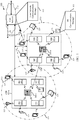
- FIG. 1 illustrates an example of a wireless communications system 100 in accordance with various aspects of the present disclosure.
- the wireless communications system 100 includes base stations 105, UEs 115, and a core network 130.
- the wireless communications system 100 may be a Long Term Evolution (LTE), LTE-Advanced (LTE-A) network, or a New Radio (NR) network.
- LTE Long Term Evolution
- LTE-A LTE-Advanced
- NR New Radio
- wireless communications system 100 may support enhanced broadband communications, ultra-reliable (i.e ., mission critical) communications, low latency communications, and communications with low-cost and low-complexity devices.
- Techniques are described herein for communicating policy information between a UE 115 and the core network 130 using NAS messages and/or control plane signaling.
- Base stations 105 may wirelessly communicate with UEs 115 via one or more base station antennas. Each base station 105 may provide communication coverage for a respective geographic coverage area 110.
- Communication links 125 shown in wireless communications system 100 may include uplink transmissions from a UE 115 to a base station 105, or downlink transmissions, from a base station 105 to a UE 115.
- Control information and data may be multiplexed on an uplink channel or downlink according to various techniques. Control information and data may be multiplexed on a downlink channel, for example, using time division multiplexing (TDM) techniques, frequency division multiplexing (FDM) techniques, or hybrid TDM-FDM techniques.
- TDM time division multiplexing
- FDM frequency division multiplexing
- control information transmitted during a transmission time interval (TTI) of a downlink channel may be distributed between different control regions in a cascaded manner (e . g ., between a common control region and one or more UE-specific control regions).
- UEs 115 may be dispersed throughout the wireless communications system 100, and each UE 115 may be stationary or mobile.
- a UE 115 may also be referred to as a mobile station, a subscriber station, a mobile unit, a subscriber unit, a wireless unit, a remote unit, a mobile device, a wireless device, a wireless communications device, a remote device, a mobile subscriber station, an access terminal, a mobile terminal, a wireless terminal, a remote terminal, a handset, a user agent, a mobile client, a client, or some other suitable terminology.
- a UE 115 may also be a cellular phone, a personal digital assistant (PDA), a wireless modem, a wireless communication device, a handheld device, a tablet computer, a laptop computer, a cordless phone, a personal electronic device, a handheld device, a personal computer, a wireless local loop (WLL) station, an Internet of Things (IoT) device, an Internet of Everything (IoE) device, a machine type communication (MTC) device, an appliance, an automobile, or the like.
- PDA personal digital assistant
- WLL wireless local loop
- IoT Internet of Things
- IoE Internet of Everything
- MTC machine type communication
- a UE 115 may also be able to communicate directly with other UEs (e.g., using a peer-to-peer (P2P) or device-to-device (D2D) protocol).
- P2P peer-to-peer
- D2D device-to-device
- One or more of a group of UEs 115 utilizing D2D communications may be within the coverage area 110 of a cell. Other UEs 115 in such a group may be outside the coverage area 110 of a cell, or otherwise unable to receive transmissions from a base station 105.
- groups of UEs 115 communicating via D2D communications may utilize a one-to-many (1:M) system in which each UE 115 transmits to every other UE 115 in the group.
- a base station 105 facilitates the scheduling of resources for D2D communications.
- D2D communications are carried out independent of a base station 105.
- Some UEs 115 may be low cost or low complexity devices, and may provide for automated communication between machines, i.e ., Machine-to-Machine (M2M) communication.
- M2M or MTC may refer to data communication technologies that allow devices to communicate with one another or a base station without human intervention.
- M2M or MTC may refer to communications from devices that integrate sensors or meters to measure or capture information and relay that information to a central server or application program that can make use of the information or present the information to humans interacting with the program or application.
- Some UEs 115 may be designed to collect information or enable automated behavior of machines. Examples of applications for MTC devices include smart metering, inventory monitoring, water level monitoring, equipment monitoring, healthcare monitoring, wildlife monitoring, weather and geological event monitoring, fleet management and tracking, remote security sensing, physical access control, and transaction-based business charging.
- an MTC device may operate using half-duplex (one-way) communications at a reduced peak rate. MTC devices may also be configured to enter a power saving "deep sleep" mode when not engaging in active communications. In some cases, MTC or IoT devices may be designed to support mission critical functions and wireless communications system may be configured to provide ultra-reliable communications for these functions.
- Base stations 105 may communicate with the core network 130 and with one another. For example, base stations 105 may interface with the core network 130 through backhaul links 132 (e.g ., S1, etc .). Base stations 105 may communicate with one another over backhaul links 134 ( e.g ., X2, etc .) either directly or indirectly ( e.g ., through core network 130). Base stations 105 may perform radio configuration and scheduling for communication with UEs 115, or may operate under the control of a base station controller (not shown). In some examples, base stations 105 may be macro cells, small cells, hot spots, or the like. Base stations 105 may also be referred to as evolved NodeBs (eNBs) or gNodeBs (gNBs) 105.
- eNBs evolved NodeBs
- gNodeBs gNodeBs
- a base station 105 may be connected by an S1 interface to the core network 130.
- the core network may be an evolved packet core (EPC), which may include at least one mobility management entity (MME), at least one serving gateway (S-GW), and at least one Packet Data Network (PDN) gateway (P-GW).
- EPC evolved packet core
- MME mobility management entity
- S-GW serving gateway
- P-GW Packet Data Network gateway
- IP Packet Data Network gateway
- All user Internet Protocol (IP) packets may be transferred through the S-GW, which itself may be connected to the P-GW.
- the P-GW may provide IP address allocation as well as other functions.
- the P-GW may be connected to the network operators IP services.
- the operators IP services may include the Internet, the Intranet, an IP Multimedia Subsystem (IMS), and a Packet-Switched (PS) Streaming Service.
- IMS IP Multimedia Subsystem
- PS Packet-Switched
- the core network 130 may provide user authentication, access authorization, tracking, Internet Protocol (IP) connectivity, and other access, routing, or mobility functions.
- IP Internet Protocol
- At least some of the network devices, such as base station 105-a may include subcomponents such as an access network entity 105-b, which may be an example of an access node controller (ANC).
- Each access network entity 105-b may communicate with a number of UEs 115 through a number of other access network transmission entities 105-c, each of which may be an example of a smart radio head, or a transmission/reception point (TRP).
- TRP transmission/reception point
- various functions of each access network entity or base station 105 may be distributed across various network devices (e.g., radio heads and access network controllers) or consolidated into a single network device (e.g ., a base station 105).
- UEs 115 may include a UE communications manager 101, which may communicate policy requests and policy information with a first core network entity using NAS messages over a control plane.
- the core network 130 may include an access and mobility management function (AMF) 120.
- AMF access and mobility management function
- the first core network entity that communicates policy requests and policy information with the UEs 115 using NAS messages over the control plane.
- the AMF 120 may be implemented by any core network entities.
- the functions of the AMF 120 may be performed by a plurality of core network entities.
- the AMF 120 include a core network communications manager 102, which may coordinate policy related communications with the UEs 115.
- the core network communications manager 102 may communicate policy requests and/or policy information with other core network entities, such as a policy control function (PCF).
- PCF policy control function
- Wireless communications system 100 may operate in an ultra-high frequency (UHF) frequency region using frequency bands from 700 MHz to 2600 MHz (2.6 GHz), although some networks (e . g ., a wireless local area network (WLAN)) may use frequencies as high as 4 GHz.
- This region may also be known as the decimeter band, since the wavelengths range from approximately one decimeter to one meter in length.
- UHF waves may propagate mainly by line of sight, and may be blocked by buildings and environmental features. However, the waves may penetrate walls sufficiently to provide service to UEs 115 located indoors.
- Wireless communications system 100 may also utilize extremely high frequency (EHF) portions of the spectrum (e . g ., from 30 GHz to 300 GHz). This region may also be known as the millimeter band, since the wavelengths range from approximately one millimeter to one centimeter in length.
- EHF antennas may be even smaller and more closely spaced than UHF antennas. In some cases, this may facilitate use of antenna arrays within a UE 115 (e.g., for directional beamforming).
- EHF transmissions may be subject to even greater atmospheric attenuation and shorter range than UHF transmissions.
- wireless communications system 100 may support millimeter wave (mmW) communications between UEs 115 and base stations 105.
- Devices operating in mmW or EHF bands may have multiple antennas to allow beamforming. That is, a base station 105 may use multiple antennas or antenna arrays to conduct beamforming operations for directional communications with a UE 115.
- Beamforming (which may also be referred to as spatial filtering or directional transmission) is a signal processing technique that may be used at a transmitter (e . g ., a base station 115) to shape and/or steer an overall antenna beam in the direction of a target receiver (e.g., a UE 115). This may be achieved by combining elements in an antenna array in such a way that transmitted signals at particular angles experience constructive interference while others experience destructive interference.
- MIMO wireless systems use a transmission scheme between a transmitter (e.g., a base station 105) and a receiver (e.g., a UE 115), where both transmitter and receiver are equipped with multiple antennas.
- Some portions of wireless communications system 100 may use beamforming.
- base station 105 may have an antenna array with a number of rows and columns of antenna ports that the base station 105 may use for beamforming in its communication with UE 115. Signals may be transmitted multiple times in different directions ( e . g ., each transmission may be beamformed differently).
- a mmW receiver e.g., a UE 115
- the antennas of a base station 105 or UE 115 may be located within one or more antenna arrays, which may support beamforming or MIMO operation.
- One or more base station antennas or antenna arrays may be collocated at an antenna assembly, such as an antenna tower.
- antennas or antenna arrays associated with a base station 105 may be located in diverse geographic locations.
- a base station 105 may multiple use antennas or antenna arrays to conduct beamforming operations for directional communications with a UE 115.
- wireless communications system 100 may be a packet-based network that operate according to a layered protocol stack.
- PDCP Packet Data Convergence Protocol
- a Radio Link Control (RLC) layer may in some cases perform packet segmentation and reassembly to communicate over logical channels.
- RLC Radio Link Control
- a Medium Access Control (MAC) layer may perform priority handling and multiplexing of logical channels into transport channels.
- the MAC layer may also use Hybrid ARQ (HARQ) to provide retransmission at the MAC layer to improve link efficiency.
- HARQ Hybrid ARQ
- the Radio Resource Control (RRC) protocol layer may provide establishment, configuration, and maintenance of an RRC connection between a UE 115 and a network device 105-c, network device 105-b, or core network 130 supporting radio bearers for user plane data.
- RRC Radio Resource Control
- PHY Physical
- SFN system frame number
- Each frame may include ten 1ms subframes numbered from 0 to 9.
- a subframe may be further divided into two .5ms slots, each of which contains 6 or 7 modulation symbol periods (depending on the length of the cyclic prefix prepended to each symbol). Excluding the cyclic prefix, each symbol contains 2048 sample periods.
- the subframe may be the smallest scheduling unit, also known as a TTI.
- a TTI may be shorter than a subframe or may be dynamically selected (e.g., in short TTI bursts or in selected component carriers using short TTIs).
- a resource element may consist of one symbol period and one subcarrier (e . g ., a 15 KHz frequency range).
- a resource block may contain 12 consecutive subcarriers in the frequency domain and, for a normal cyclic prefix in each orthogonal frequency division multiplexing (OFDM) symbol, 7 consecutive OFDM symbols in the time domain (1 slot), or 84 resource elements.
- the number of bits carried by each resource element may depend on the modulation scheme (the configuration of symbols that may be selected during each symbol period). Thus, the more resource blocks that a UE receives and the higher the modulation scheme, the higher the data rate may be.
- Wireless communications system 100 may support operation on multiple cells or carriers, a feature which may be referred to as carrier aggregation (CA) or multi-carrier operation.
- a carrier may also be referred to as a component carrier (CC), a layer, a channel, etc.
- CC component carrier
- the terms “carrier,” “component carrier,” “cell,” and “channel” may be used interchangeably herein.
- a UE 115 may be configured with multiple downlink CCs and one or more uplink CCs for carrier aggregation.
- Carrier aggregation may be used with both frequency division duplexing (FDD) and time division duplexing (TDD) component carriers.
- FDD frequency division duplexing
- TDD time division duplexing
- wireless communications system 100 may utilize enhanced component carriers (eCCs).
- eCC may be characterized by one or more features including: wider bandwidth, shorter symbol duration, shorter TTIs, and modified control channel configuration.
- an eCC may be associated with a carrier aggregation configuration or a dual connectivity configuration ( e . g ., when multiple serving cells have a suboptimal or non-ideal backhaul link).
- An eCC may also be configured for use in unlicensed spectrum or shared spectrum (where more than one operator is allowed to use the spectrum).
- An eCC characterized by wide bandwidth may include one or more segments that may be utilized by UEs 115 that are not capable of monitoring the whole bandwidth or prefer to use a limited bandwidth ( e . g ., to conserve power).
- an eCC may utilize a different symbol duration than other CCs, which may include use of a reduced symbol duration as compared with symbol durations of the other CCs. A shorter symbol duration may be associated with increased subcarrier spacing.
- a TTI in an eCC may consist of one or multiple symbols. In some cases, the TTI duration (that is, the number of symbols in a TTI) may be variable. In some cases, an eCC may utilize a different symbol duration than other CCs, which may include use of a reduced symbol duration as compared with symbol durations of the other CCs. A shorter symbol duration is associated with increased subcarrier spacing.
- a device such as a UE 115 or base station 105, utilizing eCCs may transmit wideband signals (e.g., 20, 40, 60, 80 MHz, etc.) at reduced symbol durations ( e . g ., 16.67 microseconds).
- a TTI in eCC may consist of one or multiple symbols. In some cases, the TTI duration (that is, the number of symbols in a TTI) may be variable.
- a shared radio frequency spectrum band may be utilized in an NR shared spectrum system.
- an NR shared spectrum may utilize any combination of licensed, shared, and unlicensed spectrums, among others.
- the flexibility of eCC symbol duration and subcarrier spacing may allow for the use of eCC across multiple spectrums.
- NR shared spectrum may increase spectrum utilization and spectral efficiency, specifically through dynamic vertical (e.g., across frequency) and horizontal ( e.g ., across time) sharing of resources.
- wireless system 100 may utilize both licensed and unlicensed radio frequency spectrum bands.
- wireless system 100 may employ LTE License Assisted Access (LTE-LAA) or LTE Unlicensed (LTE U) radio access technology or NR technology in an unlicensed band such as the 5Ghz Industrial, Scientific, and Medical (ISM) band.
- LTE-LAA LTE License Assisted Access
- LTE U LTE Unlicensed
- NR New Radio
- unlicensed band such as the 5Ghz Industrial, Scientific, and Medical (ISM) band.
- wireless devices such as base stations 105 and UEs 115 may employ listen-before-talk (LBT) procedures to ensure the channel is clear before transmitting data.
- LBT listen-before-talk
- operations in unlicensed bands may be based on a CA configuration in conjunction with CCs operating in a licensed band.
- Operations in unlicensed spectrum may include downlink transmissions, uplink transmissions, or both.
- Duplexing in unlicensed spectrum may be based on FDD, TDD
- a core network may include several entities (or functions) such as AMFs, PCFs, etc. implemented in software.
- a UE 115 may be in a connected mode with a base station without an active data connection. Accordingly, the UE may not be able to communicate with some virtualized entities (or functions), and this may result in reduced throughput in a wireless communications system.
- the UE 115 may be capable communicating at least some NAS messages over the control plane without an active data session (e.g., a protocol data unit (PDU) session).
- PDU protocol data unit
- the wireless communications system 100 may support techniques for efficient communication between a UE 115 and different entities (or functions) of a core network 130.
- UE 115 may interact with a single entity (or function) of a core network 130 (e.g., an AMF 120), and messages intended for other entities (or functions) may be routed appropriately by this entity. That is, as one example, for uplink communication, a UE may transmit a NAS message to AMF 120 requesting policy information from another entity of the core network 130.
- the AMF 120 may transmit (or route) the policy request or policy information to the appropriate entity (e.g., PCF).
- other entities (or functions) e . g ., PCF
- FIG. 2 illustrates an example of a wireless communications system architecture 200 that supports policy communication via control plane signaling in accordance with various aspects of the present disclosure.
- Wireless communications system architecture 200 may include UE 115-a, (R)AN 105-d, and AMF 120-a, which may be examples of the corresponding devices described with reference to FIG. 1 .
- Wireless communications system architecture 200 may also include one or more authentication server functions (AUSFs) 205, unified data management (UDM) entities 210, SMFs 215, user plane functions (UPFs) 220 (e.g., in communication with a data network (DN) 230), policy control functions (PCFs) 230, and authorization functions (AFs) 235.
- AUSFs authentication server functions
- UDM unified data management
- UPFs user plane functions
- PCFs policy control functions
- AFs authorization functions
- wireless communications system architecture 200 may include other functions or entities not displayed within the figure, or may not include one or more of the functions or entities shown.
- Various interfaces may be established between the different entities in the wireless communications system architecture 200.
- the interfaces may be denoted by N numbers, and sometimes may be called communication links.
- Such interfaces may refer to a communication link between network entities, a packet scheme, data permissions allowed between the entities, other features of the communication links, or combinations thereof.
- the AUSF 205 may provide authentication services for UE 115-a. For example, AUSF 205 may initiate authentication of UE 115-a and provide NAS security functions for a UE 115-a based on a request from AMF 120-a over communication link N12. In some cases, the authentication and security function may be based on information stored in an entity 210 (e.g., a UDM). Entity 210 (e.g., a UDM) may support an authentication credential repository and processing function (ARPF) that stores the long-term security credentials used in authentication. The AUSF 205 may retrieve information from the entity 210 (e.g., UDM) over communication link N13.
- entity 210 e.g., a UDM
- ARPF authentication credential repository and processing function
- the SMF 215 may provide session management services for UE 115-a. Specifically, SMF 215 may establish, modify, and release sessions (or bearers) for communication between UE 115-a and DN 230. For example, SMF 215 may maintain a tunnel for communication between UPF 220 and an access network (AN) node. In addition, SMF 215 may allocate and manage IP addresses for UE 115-a, select and control user plane functions, configure traffic steering at UPF 220 to route traffic to proper destinations, terminate SM parts of NAS messages, provide roaming functionality, etc.
- AN access network
- the UPF 220 may include functionality for serving as the point of interconnect to DN 230 for an external PDU session.
- UPF 220 may be the anchor point for intra-RAT and inter-RAT mobility.
- UPF 220 may route and forward packets to and from DN 230, inspect packets and enforce policy rules in the user plane, report traffic usage, handle quality of service (QoS) for user plane packets, verify uplink traffic, etc.
- the PCF 225 may support unified policy framework to govern the behavior of the network. Specifically, PCF 225 may provide policy rules to control plane functions to enforce them.
- PCF 225 may retrieve subscription information from a subscription repository at entity 210 (e.g., a UDM).
- AF 235 may support services for authorizing a UE 115-a for access to a network.
- the PCF 225 may manage policies for the various UEs 115-a of the wireless communications system architecture 200.
- the core network 130 may communicate policies to UEs 115-a in the wireless communications system architecture 200 to improve the quality of communication links and improve the quality of service.
- the PCF 225 may interact with a number of other functions (e.g., AMF 120-a, SMF 215) in the wireless communications system architecture 200.
- the AMF 120-a may be configured to provide policy information from the PCF 225-a to the UE 115-a.
- the PCF 225-a may include such policy information 345 stored on memory or the like.
- the policy information 345 may be communicated between the PCF 225-a and the AMF 120-a via a network interface 350 or a communication link.
- the network interface 350 may be an N1 interface.
- the policy information 345 may include an access network discovery and selection policy, route selection policies, an SSC mode selection policy, a network slice selection policy, a DNN selection policy, a non-seamless offload policy, other policies or combinations thereof.
- the access network discovery and selection policy may be used by the UE 115-a for selecting non-3GPP accesses and for deciding how to route traffic between the selected 3GPP and non-3GPP accesses.
- the route selection policies may be used by the UE 115-a to determine how to route outgoing traffic. Traffic can be routed to an established PDU session, can be offloaded to non-3GPP access outside a PDU session, or can trigger the establishment of a new PDU session.
- the route selection policies may include the SSC mode selection policy, the network slice selection policy, the DNN selection policy, and/or the non-seamless offload policy.
- the SSC Mode Selection Policy may be used by the UE 115-a to associate UE applications with SSC modes and to determine the PDU session which this traffic should be routed to. It is also used to determine when a new PDU session should be requested with a new SSC mode.
- the network slice selection policy may be used by the UE 115-a to associate UE applications with SM-NSSAIs and to determine the PDU session which this traffic should be routed to. It is also used to determine when a new PDU session should be requested with a new SM-NSSAI.
- the DNN Selection Policy may be used by the UE 115-a to associate UE traffic with one or more DNNs and to determine the PDU session which this traffic should be routed to.
- the non-seamless offload policy may be used by the UE 115-a to determine which traffic should be non-seamlessly offloaded to non-3GPP access (e.g., outside of a PDU session).
- a UE 115-a may access a DN 230 to exchange data packets using a PDU session.
- the PDU session may provide a PDU connectivity service, which may support the transmission of one or more PDUs between UE 115-a and the DN 230.
- An association between UE 115-a and the DN 230 in a PDU session may use internet protocol (IP) or Ethernet, or the association may be unstructured.
- IP internet protocol
- DN 230 may be an example of a local DN, central DN, public land mobile networks (PLMNs), etc.
- a UE 115-a may communicate with DN 230, SMF 215, PCF 225, etc. via the N3 communication link between RAN 105-d and UPF 220.
- the N3 communication link may be referred to as a data connection for the UE 115-a.
- UE 115-a may not have information to transmit to any of these entities (or functions) or UE 115-a may have limited information to transmit, and it may be inefficient to sustain an active data connection.
- some wireless communication systems may allow a UE 115-a to be in a connected mode without an active data connection. But without an active data connection, the UE may not be able to transmit the limited amounts of data, and this may result in reduced throughput in a wireless communications system.
- Wireless communications system architecture 200 may support efficient techniques for allowing a UE 115-a to communicate with entities (or functions) of a core network 130 without an active data connection.
- UE 115-a may transmit messages intended for other entities (or functions) to AMF 120-a, and such messages may be routed appropriately by the AMF 120.
- UE 115-a may transmit a NAS transport message to the AMF 120-a via the N1 interface.
- the AMF 120-a may transmit (or route) the message to PCF 225 via the N15 interface.
- the AMF 120-a may alter or modify the policy message before transmitting. The procedure may also be reversed.
- the PCF 225 may transmit policy information intended for the UE 115-a to the AMF 120-a via the N15 interface.
- the AMF 120-a may transmit or route the policy information to the UE 115-a via the N1 interface.
- the NAS transport message may include a routing indicator and a header that indicates the type of payload included in the message, and AMF 120-a may use this information to route the message appropriately. Accordingly, UE 115-a may be able to transmit and receive information to and from entities (or functions) of a core network without having to maintain an active data session.
- FIG. 3 illustrates an example of a wireless communications system 300 that supports policy communication via control plane signaling in accordance with various aspects of the present disclosure.
- the wireless communications system 300 may use NAS messages 335, 340 to communicate policy information between the UE 115-b and the core network 130-a.
- the UE 115-b may be an example of the UEs described with reference to FIGs. 1 and 2 .
- the UE 115-b may include a memory 305 to store data.
- Policy information 310 may be stored by the UE 115-b in the memory 305.
- the policy information 310 is associated with the UE 115-b.
- the policy information 310 is associated with the communication link established between the UE 115-b and the core network 130-b.
- the policy information 310 may include any of the policies described with reference to FIG. 2 .
- the UE 115-b may be configured to communicate using a NAS layer 315 and/or one or more lower layers 320.
- the lower layers 320 may include any number of layers in a radio access technology.
- the lower layers 320 may include a physical layer, medium access layer, radio link control layer, packet data convergence control layer, or combinations thereof.
- the NAS layer 315 may be used to manage the establishment of communication sessions and for maintain continuous communication links between the UE 115-b and the core network 130-b as the UE 115-b moves through the coverage area of the wireless network.
- the UE 115-b and the core network 130-b may be capable of exchanging NAS messages without a PDU session being established between the entities.
- a radio access technology may define one or more policies for communicating between entities.
- a policy may define a set of common procedures to be used by entities of the network. The policies may be shared with different entities so that the procedures do not have be communicated across congested wireless links as frequently. In some examples, however, the policies stored by some network entities (e.g., UE 115-b) may need to be updated due to changing network conditions or changes in the policies themselves.
- policy information may be exchanged between the UE 115-b and the core network 130-b using control plane signaling.
- NAS messages may be used to communicate policy update requests from the UE 115-b to the core network 130-b or to communicate up-to-date policy information from the core network 130-b to the UE 115-b.
- the UE 115-b may transmit a NAS policy request message 335 using control plane signaling to the core network 130-b.
- the core network 130-b may transmit a NAS policy information message 340 using control plane signaling to the UE 115-b.
- the core network 130-b may include an AMF 120-b and a PCF 225-a.
- the AMF 120-b may include a non-access stratum layer 325 similar to the NAS layer 315 and lower layers 330 similar to the lower layers 320.
- the core network entity that communicates with the UE 115-b is the AMF 120-b.
- the messages 335, 340 may be communicated using the N1 interface.
- the PCF 225-a may be the core network entity configured to store and manage the policies and policy information related to the core network 130-b. As such, the AMF 120-b may communicate policy information and/or policy update requests with the PCF 225-a. In some examples, the AMF 120-b and the PCF 225-a communicate using the N15 interface.
- the UE 115-b and the core network 130-b may exchange policy information.
- policy messages e . g ., NSSAI, SSCMP
- policy information may be carried as a payload in NAS transport message.
- policy information may be carried in an initial NAS message.
- the UE 115-b may include a request for policy provisioning and may receive from the core network 130-b the requested policy.
- the request for policy provisioning may be included in a registration request message or a service request message. It may also be piggybacked with an SM message or other messages using NAS transport.
- the AMF 120-b may perform the deciphering and integrity check and may route the message to the PCF 225-a.
- the a function may query the status of the UE 115-b through the N15 interface, if the AMF 120-b returns UE state as connected, the function may send the message to the AMF 120-b indicating that the message is to be sent to the UE 115-b.
- the AMF 120-b may encapsulate the message in a generic NAS transport payload and may send it to the UE 115-b.
- the AMF 120-b may send an idle mode indication to the PCF 225-a and may store an indication that there is a AMPEF message for the UE 115-a.
- the AMF 120-b may send the function a UE connected indication and the PCF 225-a may send the AMF 120-b the message to be sent to the UE 115-b.
- policy messages from the PCF 225-a to the UE 115-b may be triggered as a result of receiving policy provisioning request messages from the UE 115-b, updates made to the policies associated with the UE 115-b, during a registration procedure (e.g., the PCF 225-a may receive UE context establishment request), or combinations thereof.
- a visited PCF may forward any policy provisioning requests from the UE 115-b to a home PCF (hPCF) through the N7r interface and may retrieve the response from the hPCF to forward to the UE 115-b.
- these communications may use the N15r interface.
- the hPCF may also communicate any policy changes to the UE via the vPCF through the N7r interface or the N15r interface.
- the AMF in the VPLMN may have routing information for the hPCF.
- the AMF may route the UE request to the hPCF directly, and the hPCF may download the UE policies via the AMF in the VPLMN directly.
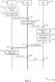
- FIG. 4 illustrates an example of a communication scheme 400 that supports policy communication via control plane signaling in accordance with various aspects of the present disclosure.
- the communication scheme 400 illustrates a policy provisioning procedure in a non-roaming scenario.
- the communication scheme 400 illustrates and describes functions and communications performed by a UE 115-c, an AMF 120-c, and a PCF 225-b.
- the AMF 120-c and the PCF 225-b may be examples of entities in the core network 130. These entities may be examples of other entities described with reference to FIGs. 1 ⁇ 3.
- the UE 115-c may identify a policy provisioning trigger.
- a policy provisioning trigger may include any event that causes the UE 115-c to need new or updated policy information.
- a policy provisioning trigger may be a change in network conditions, a change in a location of the UE 115-c, a change in the underlying policy itself, at the establishment of a communication link, or combinations thereof.
- the UE 115-c may determine location data associated with its location and transmit that location data to the core network 130 (as represented by AMF 120-c).
- the policy provisioning trigger may be based on changes in network conditions.
- the UE 115-c may be handed over to a different cell, communication link, base station, or radio head. Such changes in the communication link may mean that certain policies may need to be updated.
- Other changes in network conditions may include inter-radio access technology (RAT) handoffs, intra-RAT handoffs, radio link failure (RLF), poor communication link quality, or combinations thereof.
- RAT inter-radio access technology
- RLF radio link failure
- the policy provisioning trigger may be based on establishing a communication link. Before establishing a communication link, it is likely that the UE 115-c does not have stored all of the policies for that particular portion of the wireless network. As such, as part of connecting to the wireless network (e.g., through a radio head or through a base station), the UE 115-c may request the policies associated with the UE 115-c and that portion of the wireless network.
- the policy provisioning trigger may be based on changes in the underlying policy. Because the UE 115-c typically does not maintain the policies, the UE 115-c may identify this trigger based on communications received from the core network 130, in some examples.
- the UE 115-c may identify specific policies that should be updated. As such, when the UE 115-c sends a policy update request, the UE 115-c may include information identifying specific policies that should be updated.
- the message 415 may include an indication that the UE 115-c needs to receive updated policy information. In some examples, the message 415 may include an indication of one or more specific policies, policy types, or other policy information to be updated or retrieved.
- the UE 115-c may check the permissions related to communicating policies via control plane signaling. Not all policies may be allowed to be communicated with the control plane using NAS messages. As such, in some examples, the UE 115-c may consult a permissions list or other data structure to determine which policies may be updated using NAS messaging. In some examples, this operation is performed by a network entity. In some examples, the UE 115-c may receive a message from the core network 130 informing the UE 115-c which policies may be communicated via control plane signaling.
- the core network 130 may include a mechanism to deliver to the UE 115-c, during an RM procedure, an indication of the type of policy retrieval the UE 115-c is allowed to perform.
- the indication may indicate which types of policies the UE can request using control plane solution.
- the indication may also indicate how the UE 115-c may retrieve policies using a user plane solution.
- the indication may provide information to the UE 115-c to determine the PCF address to retrieve the policy.
- the PCF address is needed roaming scenarios for the UE 115-c to contact the vPCF, including delivering one or more of a DNN to be used to retrieve the policy, and a logical name for addressing the PCF (e.g., a uniform resource locator (URL) that the UE may translate into an IP address using DNS).
- a logical name for addressing the PCF e.g., a uniform resource locator (URL) that the UE may translate into an IP address using DNS.
- the UE 115-c may transmit a policy information request message 415 via an NAS message and control plane signaling.
- the policy information request message 415 may be generated and transmitted based on identifying that the trigger event occurred.
- the policy information request message 415 may be generated and transmitted based on the UE 115-c determining that the policies to be updated are on the control plane signaling permissions list or other data structure.
- the policy information request message 415 may include information identifying the UE 115-c and/or information identifying specific policies to be updated. In some cases, the policy information request message 415 may not include any identifiers of specific policies. Rather, in these cases, the policy information request message 415 may simply request new policy information. As such, the policy information request message 415 may be exclusive of any policy identifiers.
- the policy information request message 415 may include a UE identifier, a policy identifier, an indication that a network condition has changed, information about the changed network condition, an indication that a location of the UE 115-c has changed, information about the changed location, other information, or combination thereof.
- the UE 115-c may transmit the policy information request message 415 to the AMF 120-c of the core network.
- the policy information request message 415 may be communicated using an N1 interface.
- the policy information request message 415 may be an NAS message, in some examples.
- the policy update request may be transmitted over a NAS transport message.
- the policy information request message 415 may also be sent as part of a registration request or a service request message.
- the policy information request message 415 may include a request with no further information, or it may contain specific policies or policy types that the UE 115-c is requesting.
- the UE 115-c may have been previously configured (via USIM/via NAS signaling or other means) to know which policies can be requested via NAS.
- the AMF 120-c may receive the policy information request message 415, perform some processing, and transmit a policy information request message 425 to the proper network entity (e.g., PCF 225-b). Examples of processing performed by the AMF 120-c may include performing a deciphering and integrity check. In some examples, the AMF 120-c may append other data to the message 415 as part of generating the message 425, such as timestamps, UE identifiers, or other data. In some examples, the policy information request message 425 may be communicated via an N15 interface. In some examples, the message 425 is the same as the message 415. In some examples, the message 425 is different from the message 415. Because the message 425 is between core network entities, the message 425 may not be a NAS message, in some examples.
- the AMF 120-c may determine if the UE 115-c is allowed to request or receive certain policies. In some examples, the AMF 120-c may determine whether the UE 115-c is allowed to communicate certain policies using NAS messages. As such, the AMF 120-c may determine two-levels of permissions. First, whether the UE 115-c is entitled to certain policy information at all. Second, how the policy information is allowed to be communicated, via the control plane (NAS messaging) or the user plane. Some policy information may not be permitted to be communicated using NAS messages and control plane signaling. The determination may be based on a permission list maintained by the core network 130. In some examples, the functions of block 420 may be performed by a different core network entity (e.g., PCF 225-b).
- a different core network entity e.g., PCF 225-b
- the policy provisioning procedure may be initiated by the core network 130 and not the UE 115-c.
- the functions of blocks 405, 410, 415 425 may not be performed as a part of a policy provisioning procedure.
- such blocks may be optional in a core network initiated policy provisioning procedure.
- any core network entity e.g., AMF 120-c, PCF 225-b
- a core network entity may identify a policy provisioning trigger.
- the policy provisioning trigger may be similar to the policy provisioning triggers described with reference to block 405.
- Triggers for the core network may include receiving a policy information request message 415, 425 from the UE 115-c, a change in network conditions, a change in a location of the UE 115-c, a change in the underlying policy itself, at the establishment of a communication link, or combinations thereof.
- trigger event may be receiving the request messages 415, 425 from the UE 115-c.
- the PCF 225-b or other core network entity may determine information included in the request messages 415, 425. Sometimes the trigger event may be based on information included in the message 415, 425, such as location data or change of network data.
- the trigger event may be based on the policy changing.
- the core network 130 may change one of the policies for a variety of reasons.
- the PCF 225-b upon detecting a change in a policy, may identify that a policy provisioning trigger has occurred.
- the functions of block 430 may be performed by a different core network entity (e.g., AMF 120-c).
- the network policy provisioning in the PCF 225-b may be triggered by the UE 115-c sending a registration/mobility management (e.g., NAS) message to the network, the UE 115-c may include a request for policy provisioning and may receive from the network the requested policy.
- the PCF 225-b includes a mechanism to trigger, upon successful registration of the UE 115-c (e.g., UE context establishment request from the AMF 120-c) to trigger the network initiated policy delivery.
- the PCF 225-b may identify which policies or policy information to provide to the UE 115-c.
- the determination of the PCF 225-b may be based on the contents of the message 415, 425, a local configuration, a location of the UE 115-c, a change in the network configuration, other information available to the PCF 225-b, or combinations thereof.
- the PCF 225-b may determine what policy information cannot be sent via NAS messaging and not include that policy information.
- the PCF 225-b may determine what policy information to provide to the UE 115-c based on what policies or policy information was updated by the core network 130.
- the functions of block 430 may be performed by a different core network entity (e.g., AMF 120-c).
- the PCF 225-b may generate a policy information message 445 based on the identified policy information to provide the UE 115-c.
- the policy information message 445 may include policy information, requested policy information, UE identifiers, or other data.
- the policy information message 445 may be communicated using the N15 interface.
- the PCF 225-b may optionally determine a status of the UE 115-c.
- the PCF 225-b may query the AMF 120-c about a status of the UE 115-c. In some examples, the query may be through the N15 interface.
- the PCF 225-b may transmit the policy information to the AMF 120-c in with different information depending on the state of the UE 115-c. If the AMF 120-c returns that the UE 115-c is in a connected state, the PCF 225-b may transmit a policy information message 445 to the AMF 120-c indicating that the policy information message 445 is to be sent to the UE 115-c.
- the AMF 120-c may encapsulate the policy information message 445 in a generic NAS transport payload and sends the policy information message 450 to the UE 115-c. If the UE 115-c is in idle mode, the AMF 120-c may send an idle mode indication to the PCF 225-b and store an indication that there is a policy information message 445 waiting to be transmitted to the UE 115-c. After the AMF 120-c identifies that the UE 115-c has switched to a connected mode, the AMF 120-c may send to the PCF 225-b a UE connected indication. The PCF 225-b may send the policy information message 445 to the AMF 120-c based on receiving the UE connected indication.
- AMF 120-c may perform the querying described in block 440.
- the PCF 225-b may send the policy information message 445 to the AMF 120-c when the UE 115-c is in an idle mode.
- the AMF 120-c may store the policy information message 445 until the UE 115-c enters a connected mode.
- the policy information 445 is communicated using a N15 interface.
- the AMF 120-c may receive the policy information message 445, process the policy information message 445, and transmit a policy information message 450 to the UE 115-c.
- the policy information message 450 may be an example of a NAS message. Examples of processing performed by the AMF 120-c may include performing a deciphering and integrity check.
- the AMF 120-c may append other data to the message 445 as part of generating the message 450, such as timestamps, policy identifiers, core network entity identifiers, or other data.
- the policy information message 450 may be communicated via a N1 interface.
- the message 450 is the same as the message 445. In some examples, the message 450 is different from the message 445.
- the policy information message 450 may be a NAS message, in some examples. In some instances, the policy information message 450 may be transmitted over a NAS transport message. The policy information message 450 may also be sent as part of a registration request or a service request message. The policy information message 450 may be a registration request message, a service request message, a NAS transport message, or a session management message.
- the UE 115-c may receive a policy information message 450 (whether UE-initiated or network-initiated) enclosed in an RM response message upon successful completion of a RM procedure. In some examples, this is the same message that the PCF 225-b would send to the UE 115-c to do a push of a policy. In some examples, this message is carried in the registration accept using it as NAS transport. The AMF 120-c may trigger the PCF 225-b to initiate the policy push in some examples.
- the UE 115-c may update its policy information 310 based on the received policy information message 450. Updating may include overwriting the policy information 310 with the policy information included in the policy information message 450. In some examples, the UE 115-c may determine differences between the policy information 310 and the policy information found in the policy information message 450 and update only those differences.
- the UE 115-c may optionally transmit an acknowledgement message 460 to the core network 130.
- the acknowledgement message may be configured to confirm reception of the policy information message 450.
- the acknowledgement message 460 is a NAS message communicated using control plane signaling.
- the acknowledgement message 460 may be communicated using the N1 interface.
- the AMF 120-c may optionally transmit an acknowledgement message 465 to the PCF 225-b (via the N15 interface) based on receiving the acknowledgement message 460.
- the UE 115-c may be roaming such that it is connected to a visitor network rather than a home network.
- the UE 115-c may communicate with a visitor AMF (vAMF) using an N1 interface.
- a vAMF is an AMF associated with the visitor core network.
- the vAMF may be configured to communicate directly with a home PCF (i.e ., a hPCF).
- the hPCF may be an example of the PCF 225-b described above and associated with the UE's home core network 130.
- To communicate directly messages 425, 445, and/or 465 may be communicated with a new network interface, not the N15 interface.
- the new network interface may be used only for communicating policy requests and/or policy information with the UE 115-c.
- FIG. 5 illustrates an example of a communication scheme 500 that supports policy communication via control plane signaling in accordance with various aspects of the present disclosure.
- the communication scheme 500 illustrates a policy provisioning procedure in a roaming scenario.
- a UE 115-d is roaming when it is connected to a visitor network rather than its home network.
- the communication scheme 500 illustrates and describes functions and communications performed by a UE 115-d, a vAMF 120-d, a vPCF 225-c, and an hPCF 225-d.
- the AMF 120-d, the vPCF 225-c, and the hPCF 225-d may be examples of entities in the core network 130. These entities may be examples of other entities described with reference to FIGs. 1 ⁇ 3.
- the vAMF 120-d and vPCF 225-c may be examples of core network entities of a visitor core network of the UE 115-d.
- the hPCF 225-d may be an example of a core network entity of a home visitor core network of the UE 115-d.
- the communication scheme 500 may incorporate some of the functionality of the communication scheme 400 described with reference to FIG. 4 . Accordingly, not all functionality of the communication scheme 500 is repeated in full here.
- the UE 115-d may transmit a policy information request message 510 to the vAMF 120-d of the visitor core network.
- the policy information request message 510 may be an example of the policy information request message 415.
- the UE 115-d Before transmitting the policy information request message 510, the UE 115-d may perform the functions of blocks 405, 410.
- the policy provisioning procedure may be initiated by the core network (visitor or home) rather than the UE 115-d. In such instances, the message 510 may be optional.
- the policy information request message 510 may be an example of a NAS message transmitted via control plane signaling.
- the vAMF 120-d may determine whether the UE 115-d is roaming. If the UE 115-d is roaming, the visitor core network may alter some of its operations or functions or account for the policies of the home core network and the visitor core network. The vAMF 120-d may determine roaming through a variety of ways. In some examples, the functions of block 515 may be performed by the UE 115-d, the vPCF 225-c, or some other visitor core network entity. If the UE 115-d performs the functions of block 515, message 510 may include information about the home core network of the UE 115-d or an indication that the UE 115-d is roaming.
- the vAMF 120-d may communicate a policy information request message 520 to the vPCF 225-c.
- the policy information request message 520 may be an example of the message 425 described with reference to FIG. 4 .
- the policy information request message 520 may include the contents of the message 510.
- message 520 may include information about the home core network of the UE 115-d or an indication that the UE 115-d is roaming. Transmitting the message 520 may include performing the functions of block 420 described with reference to FIG. 4 .
- the vPCF 225-c may identify the policy information to provide to the UE 115-d.
- Block 525 may be an example of block 435 described with reference to FIG. 4 .
- block 525 may include performing the functions of blocks 430 and 440 described with reference to FIG. 4 .
- the vPCF 225-c may determine whether policy information is needed from the home core network of the UE 115-d. If policies from the home network are unnecessary, the communication scheme 500 may jump to generating and transmitting policy information message 555. Otherwise, the communication scheme 500 may proceed to transmitting policy information request message 535.
- the vPCF 225-c may generate and transmit the policy information request message 535 based on the determination of block 530.
- the policy information request message 535 may be an example of the policy information request messages 520, 425.
- message 535 may include additional information such as policy identifiers of the policies needed from the hPCF 225-d.
- the vPCF 225-c may identify which policy information is needed from the home network and include that information in message 535.
- the message 535 may be communicated via a N15r interface.
- the hPCF 225-d receives the message 535 and may identify policy information to provide to the UE 115-d. In some examples, the identified policy information may be based on the contents of the message 535.
- Block 525 may be an example of block 435 described with reference to FIG. 4 . In some examples, block 525 may include performing the functions of blocks 430 and 440 described with reference to FIG. 4 .
- the hPCF 225-d may generate and transmit a policy information message 545 that includes the identified policy information.
- the policy information message 545 may be an example of the message 445.
- the message 535 may be communicated via a N15r interface.
- the vPCF 225-c may combine the visitor network policy information and the home network policy information.
- the combining may be based at least in part on a conflict resolution procedure.
- the conflict resolution procedure may include adding combining all of the policy information together without modifying any of the procedures.
- the conflict resolution procedure may include only sending the policy information of the home network.
- the conflict resolution procedure may include only sending the policy information of the visitor network.
- the conflict resolution procedure may overruling or some of the policy information of the home network based on policy information of visitor network.
- the vPCF 225-c may compare the policy information received from the hPCF 225-d to the policy information of the visitor network or to some other data.
- the vPCF 225-c may delete any policy information from the home network that conflicts with one or more policies of the visitor network.
- the vPCF 225-d may generate and transmit a policy information message 555 based on the combined policy information generated by the vPCF 225-d.
- the policy information message 555 may be an example of the message 445 described with reference to FIG. 4 .
- the policy information message 555 may be communicated using the N15 interface.
- the vAMF 120-d may generate and transmit a policy information message 560 based on the combined policy information generated by the vPCF 225-d and the message 555.
- the policy information message 560 may be an example of the message 450 described with reference to FIG. 4 .
- the policy information message 560 may be an example of a NAS message.
- the policy information message 560 may be communicated using the N1 interface.
- the UE 115-d may identify sources of the policy information included in the policy information message 560. If the message 560 includes policy information from multiple sources, the UE 115-d may resolve conflicts between information. If the message 560 includes policy information from only one source, the UE 115-d may skip performing the functions of block 570. In some examples, the core network curates the policy information in the message 560 at block 550. In other examples, the core network merely passes on some or all of the policy information to the UE 115-d, whether conflicting or not.
- the messages 555, 560 may include information indicating the source of policy information included in the messages 555, 560.
- the UE 115-d may resolve conflicts between policy information included in the message 560.
- the UE 115-d may prioritize information from one source over information from another source.
- the UE 115-d may prioritize policy information from the hPCF 225-d over policy information from the vPCF 225-c.
- the UE 115-d may prioritize policy information from the vPCF 225-c over policy information from the hPCF 225-d.
- the UE 115-d may prioritize policy information based on both the type of policy and the source of the policy information. Where conflicts in policy information arise, the UE 115-d may update its policy information 310 based on its prioritization.
- the UE 115-d may optionally transmit an acknowledgement message 580 to the core network.
- the acknowledgement message 580 may be configured to confirm reception of the policy information message 560.
- the acknowledgement message 580 is a NAS message communicated using control plane signaling.
- the acknowledgement message 580 may be communicated using the N1 interface.
- the vAMF 120-d may optionally transmit an acknowledgement message 585 to the vPCF 225-c (via the N15 interface) based on receiving the acknowledgement message 585.
- the vPCF 225-c may optionally transmit an acknowledgement message 590 to the hPCF 225-d (via the N15r interface) based on receiving the acknowledgement message 585.
- the acknowledgement messages 580, 585, 590 may be examples of the acknowledgement messages 460, 465 described with reference to FIG. 4 .
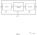
- FIG. 6 shows a block diagram 600 of a wireless device 605 that supports policy communication via control plane signaling in accordance with aspects of the present disclosure.
- Wireless device 605 may be an example of aspects of a UE 115 as described herein.
- Wireless device 605 may include receiver 610, UE communications manager 615, and transmitter 620.
- Wireless device 605 may also include a processor. Each of these components may be in communication with one another (e.g., via one or more buses).
- Receiver 610 may receive information such as packets, user data, or control information associated with various information channels (e.g., control channels, data channels, and information related to policy communication via control plane signaling, etc.). Information may be passed on to other components of the device.
- the receiver 610 may be an example of aspects of the transceiver 935 described with reference to FIG. 9 .
- the receiver 610 may utilize a single antenna or a set of antennas.
- Receiver 610 may receive, by a UE, a first NAS message over a control plane that includes policy information associated with the UE.
- UE communications manager 615 may be an example of aspects of the communications manager 915 described with reference to FIG. 9 .
- UE communications manager 615 and/or at least some of its various sub-components may be implemented in hardware, software executed by a processor, firmware, or any combination thereof. If implemented in software executed by a processor, the functions of the UE communications manager 615 and/or at least some of its various sub-components may be executed by a general-purpose processor, a digital signal processor (DSP), an application-specific integrated circuit (ASIC), an field-programmable gate array (FPGA) or other programmable logic device, discrete gate or transistor logic, discrete hardware components, or any combination thereof designed to perform the functions described in the present disclosure.
- DSP digital signal processor
- ASIC application-specific integrated circuit
- FPGA field-programmable gate array
- the UE communications manager 615 and/or at least some of its various sub-components may be physically located at various positions, including being distributed such that portions of functions are implemented at different physical locations by one or more physical devices.
- UE communications manager 615 and/or at least some of its various subcomponents may be a separate and distinct component in accordance with various aspects of the present disclosure.
- UE communications manager 615 and/or at least some of its various sub-components may be combined with one or more other hardware components, including but not limited to an I/O component, a transceiver, a network server, another computing device, one or more other components described in the present disclosure, or a combination thereof in accordance with various aspects of the present disclosure.
- UE communications manager 615 may identify the policy information based on receiving the first NAS message and update the policy information stored by the UE based on the received policy information.
- Transmitter 620 may transmit signals generated by other components of the device.
- the transmitter 620 may be collocated with a receiver 610 in a transceiver module.
- the transmitter 620 may be an example of aspects of the transceiver 935 described with reference to FIG. 9 .
- the transmitter 620 may utilize a single antenna or a set of antennas.
- Transmitter 620 may transmit a second NAS message over the control plane requesting the policy information from the core network, where receiving the first NAS message is based on transmitting the second NAS message.
- the second NAS message includes a request for the policy information exclusive of any specific policy information identifiers.
- the second NAS message is one of a registration request message, a service request message, a NAS transport message, or a session management message.
- the first NAS message is generated without the UE transmitting a policy request message.
- FIG. 7 shows a block diagram 700 of a wireless device 705 that supports policy communication via control plane signaling in accordance with aspects of the present disclosure.
- Wireless device 705 may be an example of aspects of a wireless device 605 or a UE 115 as described with reference to FIG. 6 .
- Wireless device 705 may include receiver 710, UE communications manager 715, and transmitter 720.
- Wireless device 705 may also include a processor. Each of these components may be in communication with one another (e.g., via one or more buses).
- Receiver 710 may receive information such as packets, user data, or control information associated with various information channels (e.g., control channels, data channels, and information related to policy communication via control plane signaling, etc.). Information may be passed on to other components of the device.
- the receiver 10 may be an example of aspects of the transceiver 935 described with reference to FIG. 9 .
- the receiver 710 may utilize a single antenna or a set of antennas.
- UE communications manager 715 may be an example of aspects of the UE communications manager 915 described with reference to FIG. 9 .
- UE communications manager 715 may also include policy manager 725.
- Policy manager 725 may identify the policy information based on receiving the first NAS message, update the policy information stored by the UE based on the received policy information, and identify an individual policy to be updated, the second NAS message including data indicating the individual policy, where identifying the policy provisioning trigger is based on identifying the individual policy.
- Transmitter 720 may transmit signals generated by other components of the device.
- the transmitter 720 may be collocated with a receiver 710 in a transceiver module.
- the transmitter 720 may be an example of aspects of the transceiver 935 described with reference to FIG. 9 .
- the transmitter 720 may utilize a single antenna or a set of antennas.
- FIG. 8 shows a block diagram 800 of a UE communications manager 815 that supports policy communication via control plane signaling in accordance with aspects of the present disclosure.
- the UE communications manager 815 may be an example of aspects of a UE communications manager 615, a UE communications manager 715, or a UE communications manager 915 described with reference to FIGs. 6 , 7 , and 9 .
- the UE communications manager 815 may include policy manager 820, priority manager 825, acknowledgement manager 830, trigger manager 835, location manager 840, and permission manager 845. Each of these modules may communicate, directly or indirectly, with one another (e.g., via one or more buses).
- Policy manager 820 may identify the policy information based on receiving the first NAS message, update the policy information stored by the UE based on the received policy information, and identify an individual policy to be updated, the second NAS message including data indicating the individual policy, where identifying the policy provisioning trigger is based on identifying the individual policy.
- Priority manager 825 may prioritize the received policy information based on which core network entity generated the received policy information, where updating the policy information is based on the prioritizing and prioritize a first subset of the policy information received from a visiting core network over a second subset of the policy information received from a home core network of the UE, where updating the policy information is based at least in part the prioritizing.
- Acknowledgement manager 830 may transmit an acknowledgement NAS message over the control plane based on receiving the first NAS message.
- Trigger manager 835 may identify a policy provisioning trigger indicating that UE is to receive the policy information associated with the UE from a core network.
- Location manager 840 may identify a location of the UE, where identifying the policy provisioning trigger is based on identifying the location.
- Permission manager 845 may receive a permission message indicating a first subset of the policy information capable of being communicated over the control plane, where transmitting the second NAS message is based on the first subset of the policy information.
- FIG. 9 shows a diagram of a system 900 including a device 905 that supports policy communication via control plane signaling in accordance with one or more aspects of the present disclosure.
- Device 905 may be an example of or include the components of wireless device 605, wireless device 705, or a UE 115 as described above, e.g., with reference to FIGs. 1 , 6 and 7 .
- Device 905 may include components for bi-directional voice and data communications including components for transmitting and receiving communications, including UE communications manager 915, processor 920, memory 925, software 930, transceiver 935, antenna 940, and I/O controller 945. These components may be in electronic communication via one or more busses (e.g., bus 910).
- Device 905 may communicate wirelessly with one or more base stations 105.
- Processor 920 may include an intelligent hardware device, (e.g., a general-purpose processor, a DSP, a central processing unit (CPU), a microcontroller, an ASIC, an FPGA, a programmable logic device, a discrete gate or transistor logic component, a discrete hardware component, or any combination thereof).
- processor 920 may be configured to operate a memory array using a memory controller.
- a memory controller may be integrated into processor 920.
- Processor 920 may be configured to execute computer-readable instructions stored in a memory to perform various functions (e.g., functions or tasks supporting policy communication via control plane signaling).
- Memory 925 may include random access memory (RAM) and read only memory (ROM).
- the memory 925 may store computer-readable, computer-executable software 930 including instructions that, when executed, cause the processor to perform various functions described herein.
- the memory 925 may contain, among other things, a basic input/output system (BIOS) which may control basic hardware and/or software operation such as the interaction with peripheral components or devices.
- BIOS basic input/output system
- Software 930 may include code to implement aspects of the present disclosure, including code to support policy communication via control plane signaling.
- Software 930 may be stored in a non-transitory computer-readable medium such as system memory or other memory. In some cases, the software 930 may not be directly executable by the processor but may cause a computer (e.g., when compiled and executed) to perform functions described herein.
- Transceiver 935 may communicate bi-directionally, via one or more antennas, wired, or wireless links as described above.
- the transceiver 935 may represent a wireless transceiver and may communicate bi-directionally with another wireless transceiver.
- the transceiver 935 may also include a modem to modulate the packets and provide the modulated packets to the antennas for transmission, and to demodulate packets received from the antennas.
- the wireless device may include a single antenna 940. However, in some cases the device may have more than one antenna 940, which may be capable of concurrently transmitting or receiving multiple wireless transmissions.
- I/O controller 945 may manage input and output signals for device 905. I/O controller 945 may also manage peripherals not integrated into device 905. In some cases, I/O controller 945 may represent a physical connection or port to an external peripheral. In some cases, I/O controller 945 may utilize an operating system such as iOS®, ANDROID®, MS-DOS®, MS-WINDOWS®, OS/2®, UNIX®, LINUX®, or another known operating system. In other cases, I/O controller 945 may represent or interact with a modem, a keyboard, a mouse, a touchscreen, or a similar device. In some cases, I/O controller 945 may be implemented as part of a processor. In some cases, a user may interact with device 905 via I/O controller 945 or via hardware components controlled by I/O controller 945.
- I/O controller 945 may manage input and output signals for device 905. I/O controller 945 may also manage peripherals not integrated into device 905. In some cases, I/O controller 945 may represent a
- FIG. 10 shows a block diagram 1000 of a wireless device 1005 that supports policy communication via control plane signaling in accordance with one or more aspects of the present disclosure.
- Wireless device 1005 may be an example of aspects of a core network entity 120 or 225 as described with reference to FIG. 1 .
- Wireless device 1005 may include receiver 1010, core network entity communications manager 1015, and transmitter 1020.
- Wireless device 1005 may also include a processor. Each of these components may be in communication with one another (e.g., via one or more buses).
- Receiver 1010 may receive information such as packets, user data, or control information associated with various information channels (e.g., control channels, data channels, and information related to policy communication via control plane signaling, etc.). Information may be passed on to other components of the device.
- the receiver 1010 may be an example of aspects of the transceiver 1335 described with reference to FIG. 13 .
- the receiver 1010 may utilize a single antenna or a set of antennas.
- Receiver 1010 may receive a second message via control plane signaling from the UE, the second message requesting the policy information from the core network, where identifying the policy provisioning trigger is based on receiving the second message.
- Core network entity communications manager 1015 may be an example of aspects of the core network entity communications manager 1315 described with reference to FIG. 13 .
- Core network entity communications manager 1015 and/or at least some of its various sub-components may be implemented in hardware, software executed by a processor, firmware, or any combination thereof. If implemented in software executed by a processor, the functions of the core network entity communications manager 1015 and/or at least some of its various sub-components may be executed by a general-purpose processor, a DSP, an ASIC, an FPGA or other programmable logic device, discrete gate or transistor logic, discrete hardware components, or any combination thereof designed to perform the functions described in the present disclosure.
- the core network entity communications manager 1015 and/or at least some of its various sub-components may be physically located at various positions, including being distributed such that portions of functions are implemented at different physical locations by one or more physical devices.
- core network entity communications manager 1015 and/or at least some of its various sub-components may be a separate and distinct component in accordance with various aspects of the present disclosure.
- core network entity communications manager 1015 and/or at least some of its various sub-components may be combined with one or more other hardware components, including but not limited to an I/O component, a transceiver, a network server, another computing device, one or more other components described in the present disclosure, or a combination thereof in accordance with various aspects of the present disclosure.
- Core network entity communications manager 1015 may identify a policy provisioning trigger indicating that a UE is to receive policy information associated with the UE from a core network and identify the policy information based on the policy provisioning trigger.
- Transmitter 1020 may transmit signals generated by other components of the device.
- the transmitter 1020 may be collocated with a receiver 1010 in a transceiver module.
- the transmitter 1020 may be an example of aspects of the transceiver 1335 described with reference to FIG. 13 .
- the transmitter 1020 may utilize a single antenna or a set of antennas.
- Transmitter 1020 may transmit a first message via control plane signaling to the UE, the first message including the identified policy information.
- the first control message is a NAS message.
- FIG. 11 shows a block diagram 1100 of a wireless device 1105 that supports policy communication via control plane signaling in accordance with one or more aspects of the present disclosure.
- Wireless device 1105 may be an example of aspects of a wireless device 1005 or a core network entity 120 or 225 as described with reference to FIGs. 1 and 10 .
- Wireless device 1105 may include receiver 1110, core network entity communications manager 1115, and transmitter 1120.
- Wireless device 1105 may also include a processor. Each of these components may be in communication with one another (e.g., via one or more buses).
- Receiver 1110 may receive information such as packets, user data, or control information associated with various information channels (e.g., control channels, data channels, and information related to policy communication via control plane signaling, etc.). Information may be passed on to other components of the device.
- the receiver 1110 may be an example of aspects of the transceiver 1335 described with reference to FIG. 13 .
- the receiver 1110 may utilize a single antenna or a set of antennas.
- Core network entity communications manager 1115 may be an example of aspects of the core network entity communications manager 1315 described with reference to FIG. 13 . Core network entity communications manager 1115 may also include trigger manager 1125 and policy manager 1130.
- Trigger manager 1125 may identify a policy provisioning trigger indicating that a UE is to receive policy information associated with the UE from a core network.
- Policy manager 1130 may identify the policy information based on the policy provisioning trigger, identify a change in a policy, where identifying the policy provisioning trigger is based on the change in the policy, identify a change in a location of the UE, where identifying the policy provisioning trigger is based on the change in the location, and identify what policy information the UE is permitted to receive over the control plane, where transmitting the first message is based on the identifying.
- Transmitter 1120 may transmit signals generated by other components of the device.
- the transmitter 1120 may be collocated with a receiver 1110 in a transceiver module.
- the transmitter 1120 may be an example of aspects of the transceiver 1335 described with reference to FIG. 13 .
- the transmitter 1120 may utilize a single antenna or a set of antennas.
- FIG. 12 shows a block diagram 1200 of a core network entity communications manager 1215 that supports policy communication via control plane signaling in accordance with one or more aspects of the present disclosure.
- the core network entity communications manager 1215 may be an example of aspects of a core network entity communications manager 1315 described with reference to FIGs. 10 , 11 , and 13 .
- the core network entity communications manager 1215 may include trigger manager 1220, policy manager 1225, roaming manager 1230, acknowledgement manager 1235, and link manager 1240. Each of these modules may communicate, directly or indirectly, with one another (e.g., via one or more buses).
- Trigger manager 1220 may identify a policy provisioning trigger indicating that a UE is to receive policy information associated with the UE from a core network.
- Policy manager 1225 may identify the policy information based on the policy provisioning trigger, identify a change in a policy, where identifying the policy provisioning trigger is based on the change in the policy, identify a change in a location of the UE, where identifying the policy provisioning trigger is based on the change in the location, and identify what policy information the UE is permitted to receive over the control plane, where transmitting the first message is based on the identifying.
- Roaming manager 1230 may identify that the UE is roaming such that the UE is connected to a visiting core network rather than a home core network, request, by a visiting core network entity, the policy information directly from a home policy management entity, request, by a first visiting core network entity, the policy information from a visiting policy management entity associated with the UE, request, by the visiting policy management entity, policy information from a home policy management entity associated with the UE, combine policy information from the home policy management entity and policy information from the visiting policy management entity based on a conflict resolution procedure, where the first message includes the combined policy information, and determine, by the visiting policy management entity, whether to request policy information from a home policy management entity associated with the UE.
- Acknowledgement manager 1235 may receive an acknowledgement message via control plane signaling from the UE based on transmitting the first message.
- Link manager 1240 may determine whether the UE is in a connected mode or an idle mode, where transmitting the first message is based on the determining.
- FIG. 13 shows a diagram of a system 1300 including a device 1305 that supports policy communication via control plane signaling in accordance with one or more aspects of the present disclosure.
- Device 1305 may be an example of or include the components of core network entity 120 or 225 as described above, e.g., with reference to FIG. 1 .
- Device 1305 may include components for bi-directional voice and data communications including components for transmitting and receiving communications, including core network entity communications manager 1315, processor 1320, memory 1325, software 1330, transceiver 1335, and I/O controller 1340. These components may be in electronic communication via one or more busses (e.g., bus 1310).
- busses e.g., bus 1310
- Processor 1320 may include an intelligent hardware device, (e.g., a general-purpose processor, a DSP, a CPU, a microcontroller, an ASIC, an FPGA, a programmable logic device, a discrete gate or transistor logic component, a discrete hardware component, or any combination thereof).
- processor 1320 may be configured to operate a memory array using a memory controller.
- a memory controller may be integrated into processor 1320.
- Processor 1320 may be configured to execute computer-readable instructions stored in a memory to perform various functions (e . g ., functions or tasks supporting policy communication via control plane signaling).
- Memory 1325 may include RAM and ROM.
- the memory 1325 may store computer-readable, computer-executable software 1330 including instructions that, when executed, cause the processor to perform various functions described herein.
- the memory 1325 may contain, among other things, a BIOS which may control basic hardware and/or software operation such as the interaction with peripheral components or devices.
- Software 1330 may include code to implement aspects of the present disclosure, including code to support policy communication via control plane signaling.
- Software 1330 may be stored in a non-transitory computer-readable medium such as system memory or other memory. In some cases, the software 1330 may not be directly executable by the processor but may cause a computer (e.g., when compiled and executed) to perform functions described herein.
- Transceiver 1335 may communicate bi-directionally, via one or more antennas, wired, or wireless links as described above.
- the transceiver 1335 may represent a wireless transceiver and may communicate bi-directionally with another wireless transceiver.
- the transceiver 1335 may also include a modem to modulate the packets and provide the modulated packets to the antennas for transmission, and to demodulate packets received from the antennas.
- I/O controller 1340 may manage input and output signals for device 1305. I/O controller 1340 may also manage peripherals not integrated into device 1305. In some cases, I/O controller 1340 may represent a physical connection or port to an external peripheral. In some cases, I/O controller 1340 may utilize an operating system such as iOS®, ANDROID®, MS-DOS®, MS-WINDOWS®, OS/2®, UNIX®, LINUX®, or another known operating system. In other cases, I/O controller 1340 may represent or interact with a modem, a keyboard, a mouse, a touchscreen, or a similar device. In some cases, I/O controller 1340 may be implemented as part of a processor. In some cases, a user may interact with device 1305 via I/O controller 1340 or via hardware components controlled by I/O controller 1340.
- FIG. 14 shows a flowchart illustrating a method 1400 for policy communication via control plane signaling in accordance with aspects of the present disclosure.
- the operations of method 1400 may be implemented by a UE 115 or its components as described herein.
- the operations of method 1400 may be performed by a communications manager as described with reference to FIGs. 6 through 9 .
- a UE 115 may execute a set of codes to control the functional elements of the device to perform the functions described below. Additionally or alternatively, the UE 115 may perform aspects of the functions described below using special-purpose hardware.
- the UE 115 may receive, by a UE, a first NAS message over a control plane that includes policy information associated with the UE.
- the operations of 1405 may be performed according to the methods described herein. In certain examples, aspects of the operations of 1405 may be performed by a receiver as described with reference to FIGs. 6 through 9 .
- the UE 115 may identify the policy information based at least in part on receiving the first NAS message.
- the operations of 1410 may be performed according to the methods described herein. In certain examples, aspects of the operations of 1410 may be performed by a policy manager as described with reference to FIGs. 6 through 9 .
- the UE 115 may update the policy information stored by the UE based at least in part on the received policy information.
- the operations of 1415 may be performed according to the methods described herein. In certain examples, aspects of the operations of 1415 may be performed by a policy manager as described with reference to FIGs. 6 through 9 .
- FIG. 15 shows a flowchart illustrating a method 1500 for policy communication via control plane signaling in accordance with one or more aspects of the present disclosure.
- the operations of method 1500 may be implemented by a core network entity 120 or 225 or its components as described herein.
- the operations of method 1500 may be performed by a core network entity communications manager as described with reference to FIGs. 10 through 13 .
- a core network entity 120 or 225 may execute a set of codes to control the functional elements of the device to perform the functions described below. Additionally or alternatively, the core network entity 120 or 225 may perform aspects of the functions described below using special-purpose hardware.
- the core network entity 120 or 225 may identify a policy provisioning trigger indicating that a UE is to receive policy information associated with the UE from a core network.
- the operations of block 1505 may be performed according to the methods described with reference to FIGs. 1 through 5 . In certain examples, aspects of the operations of block 1505 may be performed by a trigger manager as described with reference to FIGs. 10 through 13 .
- the core network entity 120 or 225 may identify the policy information based at least in part on the policy provisioning trigger.
- the operations of block 1510 may be performed according to the methods described with reference to FIGs. 1 through 5 . In certain examples, aspects of the operations of block 1510 may be performed by a policy manager as described with reference to FIGs. 10 through 13 .
- the core network entity 120 or 225 may transmit a first message via control plane signaling to the UE, the first message including the identified policy information.
- the operations of block 1515 may be performed according to the methods described with reference to FIGs. 1 through 5 . In certain examples, aspects of the operations of block 1515 may be performed by a transmitter as described with reference to FIGs. 10 through 13 .
- FIG. 16 shows a flowchart illustrating a method 1600 for policy communication via control plane signaling in accordance with one or more aspects of the present disclosure.
- the operations of method 1600 may be implemented by a UE 115 or its components as described herein.
- the operations of method 1600 may be performed by a UE communications manager as described with reference to FIGs. 6 through 9 .
- a UE 115 may execute a set of codes to control the functional elements of the device to perform the functions described below. Additionally or alternatively, the UE 115 may perform aspects of the functions described below using special-purpose hardware.
- the UE 115 may identify a policy provisioning trigger indicating that a UE is to receive policy information associated with the UE from a core network.
- the operations of block 1605 may be performed according to the methods described with reference to FIGs. 1 through 5 . In certain examples, aspects of the operations of block 1605 may be performed by a trigger manager as described with reference to FIGs. 6 through 9 .
- the UE 115 may transmit a first NAS message over a control plane requesting the policy information from the core network.
- the operations of block 1610 may be performed according to the methods described with reference to FIGs. 1 through 5 . In certain examples, aspects of the operations of block 1610 may be performed by a transmitter as described with reference to FIGs. 6 through 9 .
- the UE 115 may receive a second NAS message over the control plane that includes the policy information, the second NAS message being based at least in part on the first NAS message.
- the operations of block 1615 may be performed according to the methods described with reference to FIGs. 1 through 5 . In certain examples, aspects of the operations of block 1615 may be performed by a receiver as described with reference to FIGs. 6 through 9 .
- FIG. 17 shows a flowchart illustrating a method 1700 for policy communication via control plane signaling in accordance with one or more aspects of the present disclosure.
- the operations of method 1700 may be implemented by a UE 115 or its components as described herein.
- the operations of method 1700 may be performed by a UE communications manager as described with reference to FIGs. 6 through 9 .
- a UE 115 may execute a set of codes to control the functional elements of the device to perform the functions described below. Additionally or alternatively, the UE 115 may perform aspects of the functions described below using special-purpose hardware.
- the UE 115 may identify an individual policy to be updated, the first NAS message including data indicating the individual policy.
- the operations of block 1705 may be performed according to the methods described with reference to FIGs. 1 through 5 . In certain examples, aspects of the operations of block 1705 may be performed by a policy manager as described with reference to FIGs. 6 through 9 .
- the UE 115 may identify a policy provisioning trigger indicating that a UE is to receive policy information associated with the UE from a core network based at least in part on identifying the individual policy.
- the operations of block 1710 may be performed according to the methods described with reference to FIGs. 1 through 5 . In certain examples, aspects of the operations of block 1710 may be performed by a trigger manager as described with reference to FIGs. 6 through 9 .
- the UE 115 may transmit a first NAS message over a control plane requesting the policy information from the core network.
- the operations of block 1715 may be performed according to the methods described with reference to FIGs. 1 through 5 . In certain examples, aspects of the operations of block 1715 may be performed by a transmitter as described with reference to FIGs. 6 through 9 .
- the UE 115 may receive a second NAS message over the control plane that includes the policy information, the second NAS message being based at least in part on the first NAS message.
- the operations of block 1720 may be performed according to the methods described with reference to FIGs. 1 through 5 . In certain examples, aspects of the operations of block 1720 may be performed by a receiver as described with reference to FIGs. 6 through 9 .
- the UE 115 may update policy information stored by the UE based at least in part on the received policy information.
- the operations of block 1725 may be performed according to the methods described with reference to FIGs. 1 through 5 . In certain examples, aspects of the operations of block 1725 may be performed by a policy manager as described with reference to FIGs. 6 through 9 .
- FIG. 18 shows a flowchart illustrating a method 1800 for policy communication via control plane signaling in accordance with one or more aspects of the present disclosure.
- the operations of method 1800 may be implemented by a UE 115 or its components as described herein.
- the operations of method 1800 may be performed by a UE communications manager as described with reference to FIGs. 6 through 9 .
- a UE 115 may execute a set of codes to control the functional elements of the device to perform the functions described below. Additionally or alternatively, the UE 115 may perform aspects of the functions described below using special-purpose hardware.
- the UE 115 may receive, by a UE, a NAS message over a control plane that includes policy information associated with the UE.
- the operations of block 1805 may be performed according to the methods described with reference to FIGs. 1 through 5 . In certain examples, aspects of the operations of block 1805 may be performed by a receiver as described with reference to FIGs. 6 through 9 .
- the UE 115 may update policy information stored by the UE based at least in part on the received policy information.
- the operations of block 1810 may be performed according to the methods described with reference to FIGs. 1 through 5 . In certain examples, aspects of the operations of block 1810 may be performed by a policy manager as described with reference to FIGs. 6 through 9 .
- CDMA code division multiple access
- TDMA time division multiple access
- FDMA frequency division multiple access
- OFDMA orthogonal frequency division multiple access
- SC-FDMA single carrier frequency division multiple access
- CDMA2000 covers IS-2000, IS-95, and IS-856 standards.
- IS-2000 Releases may be commonly referred to as CDMA2000 IX, IX, etc.
- IS-856 (TIA-856) is commonly referred to as CDMA2000 1xEV-DO, High Rate Packet Data (HRPD), etc.
- UTRA includes Wideband CDMA (WCDMA) and other variants of CDMA.
- WCDMA Wideband CDMA
- a TDMA system may implement a radio technology such as Global System for Mobile Communications (GSM).
- GSM Global System for Mobile Communications
- An OFDMA system may implement a radio technology such as Ultra Mobile Broadband (UMB), Evolved UTRA (E-UTRA), Institute of Electrical and Electronics Engineers (IEEE) 802.11 (Wi-Fi), IEEE 802.16 (WiMAX), IEEE 802.20, Flash-OFDM, etc.
- UMB Ultra Mobile Broadband
- E-UTRA Evolved UTRA
- IEEE Institute of Electrical and Electronics Engineers
- Wi-Fi Wi-Fi
- WiMAX IEEE 802.16
- IEEE 802.20 Flash-OFDM
- UMB Ultra Mobile Broadband
- E-UTRA Evolved UTRA
- IEEE 802.11 Wi-Fi
- WiMAX IEEE 802.16
- Flash-OFDM Flash-OFDM
- UTRA and E-UTRA are part of Universal Mobile Telecommunications System (UMTS).
- LTE and LTE-A are releases of UMTS that use E-UTRA.
- LTE or NR may be described for purposes of example, and LTE or NR terminology may be used in much of the description, the techniques described herein are applicable beyond LTE or NR applications.
- the term evolved node B may be generally used to describe the base stations.
- the wireless communications system or systems described herein may include a heterogeneous LTE/LTE-A or NR network in which different types of eNBs provide coverage for various geographical regions.
- each eNB, next generation NodeB (gNB), or base station may provide communication coverage for a macro cell, a small cell, or other types of cell.
- the term "cell” may be used to describe a base station, a carrier or component carrier associated with a base station, or a coverage area (e.g., sector, etc.) of a carrier or base station, depending on context.
- Base stations may include or may be referred to by those skilled in the art as a base transceiver station, a radio base station, an access point, a radio transceiver, a NodeB, eNodeB (eNB), gNB, Home NodeB, a Home eNodeB, or some other suitable terminology.
- the geographic coverage area for a base station may be divided into sectors making up only a portion of the coverage area.
- the wireless communications system or systems described herein may include base stations of different types (e.g., macro or small cell base stations).
- the UEs described herein may be able to communicate with various types of base stations and network equipment including macro eNBs, small cell eNBs, gNBs, relay base stations, and the like. There may be overlapping geographic coverage areas for different technologies.
- a macro cell generally covers a relatively large geographic area (e.g., several kilometers in radius) and may allow unrestricted access by UEs with service subscriptions with the network provider.
- a small cell is a lower-powered base station, as compared with a macro cell, that may operate in the same or different (e.g., licensed, unlicensed, etc.) frequency bands as macro cells.
- Small cells may include pico cells, femto cells, and micro cells according to various examples.
- a pico cell for example, may cover a small geographic area and may allow unrestricted access by UEs with service subscriptions with the network provider.
- a femto cell may also cover a small geographic area (e.g., a home) and may provide restricted access by UEs having an association with the femto cell (e.g., UEs in a closed subscriber group (CSG), UEs for users in the home, and the like).
- An eNB for a macro cell may be referred to as a macro eNB.
- An eNB for a small cell may be referred to as a small cell eNB, a pico eNB, a femto eNB, or a home eNB.
- An eNB may support one or multiple (e.g., two, three, four, and the like) cells (e.g., component carriers).
- the wireless communications system or systems described herein may support synchronous or asynchronous operation.
- the base stations may have similar frame timing, and transmissions from different base stations may be approximately aligned in time.
- the base stations may have different frame timing, and transmissions from different base stations may not be aligned in time.
- the techniques described herein may be used for either synchronous or asynchronous operations.
- Each communication link described herein including, for example, wireless communications system 100 and 200 of FIGs. 1 and 2 —may include one or more carriers, where each carrier may be a signal made up of multiple sub-carriers (e.g., waveform signals of different frequencies).
- Information and signals described herein may be represented using any of a variety of different technologies and techniques.
- data, instructions, commands, information, signals, bits, symbols, and chips that may be referenced throughout the above description may be represented by voltages, currents, electromagnetic waves, magnetic fields or particles, optical fields or particles, or any combination thereof.
- a general-purpose processor may be a microprocessor, but in the alternative, the processor may be any conventional processor, controller, microcontroller, or state machine.
- a processor may also be implemented as a combination of computing devices (e.g., a combination of a DSP and a microprocessor, multiple microprocessors, one or more microprocessors in conjunction with a DSP core, or any other such configuration).
- the functions described herein may be implemented in hardware, software executed by a processor, firmware, or any combination thereof. If implemented in software executed by a processor, the functions may be stored on or transmitted over as one or more instructions or code on a computer-readable medium. Other examples and implementations are within the scope of the disclosure and appended claims. For example, due to the nature of software, functions described above can be implemented using software executed by a processor, hardware, firmware, hardwiring, or combinations of any of these. Features implementing functions may also be physically located at various positions, including being distributed such that portions of functions are implemented at different physical locations.
- Computer-readable media includes both non-transitory computer storage media and communication media including any medium that facilitates transfer of a computer program from one place to another.
- a non-transitory storage medium may be any available medium that can be accessed by a general purpose or special purpose computer.
- non-transitory computer-readable media may comprise RAM, ROM, electrically erasable programmable read only memory (EEPROM), compact disk (CD) ROM or other optical disk storage, magnetic disk storage or other magnetic storage devices, or any other non-transitory medium that can be used to carry or store desired program code means in the form of instructions or data structures and that can be accessed by a general-purpose or special-purpose computer, or a general-purpose or special-purpose processor.
- RAM random access memory
- ROM read only memory
- EEPROM electrically erasable programmable read only memory
- CD compact disk
- magnetic disk storage or other magnetic storage devices or any other non-transitory medium that can be used to carry or store desired program code means in the form of instructions or data structures
- any connection is properly termed a computer-readable medium.
- the software is transmitted from a website, server, or other remote source using a coaxial cable, fiber optic cable, twisted pair, digital subscriber line (DSL), or wireless technologies such as infrared, radio, and microwave
- the coaxial cable, fiber optic cable, twisted pair, DSL, or wireless technologies such as infrared, radio, and microwave are included in the definition of medium.
- Disk and disc include CD, laser disc, optical disc, digital versatile disc (DVD), floppy disk and Blu-ray disc where disks usually reproduce data magnetically, while discs reproduce data optically with lasers. Combinations of the above are also included within the scope of computer-readable media.
Description
- The following relates generally to wireless communication, and more specifically to policy communication via control plane signaling.
- Wireless communications systems are widely deployed to provide various types of communication content such as voice, video, packet data, messaging, broadcast, and so on. These systems may be capable of supporting communication with multiple users by sharing the available system resources (e.g., time, frequency, and power). Examples of such multiple-access systems include code division multiple access (CDMA) systems, time division multiple access (TDMA) systems, frequency division multiple access (FDMA) systems, and orthogonal frequency division multiple access (OFDMA) systems, (e.g., a Long Term Evolution (LTE) system, or a New Radio (NR) system). A wireless multiple-access communications system may include a number of base stations or access network nodes, each simultaneously supporting communication for multiple communication devices, which may be otherwise known as user equipment (UE).
-
US 2016/0248686 A1 relates to network tokens, and more specifically to the derivation, provisioning, and use of network tokens that are associated with data flows to facilitate packet steering and/or verification that a device is accessing only authorized application services. - In some wireless communications systems, policies may be exchanged between the UE and the network. The policies may define a set of procedure used to establish and maintain communication links. Wireless communications systems include policies to reduce control signaling overhead. Some procedures occur frequently and the variables used in those procedure may remain fairly static for a communication link. By storing these policies at each entity in the wireless communications system, network signaling congestion and network overhead may be reduced.
- Aspects of the invention are defined in the claims.
-
-
FIG. 1 illustrates an example of a system for wireless communication that supports policy communication via control plane signaling in accordance with one or more aspects of the present disclosure. -
FIG. 2 illustrates an example of a wireless communications system architecture that supports policy communication via control plane signaling in accordance with one or more aspects of the present disclosure. -
FIG. 3 illustrates an example of a wireless communications system that supports policy communication via control plane signaling in accordance with one or more aspects of the present disclosure. -
FIG. 4 illustrates an example of a communication scheme that supports policy communication via control plane signaling in accordance with one or more aspects of the present disclosure. -
FIG. 5 illustrates an example of a communication scheme that supports policy communication via control plane signaling in accordance with one or more aspects of the present disclosure. -
FIGs. 6 through 8 show block diagrams of a device that supports policy communication via control plane signaling in accordance with one or more aspects of the present disclosure. -
FIG. 9 illustrates a block diagram of a system including a UE that supports policy communication via control plane signaling in accordance with one or more aspects of the present disclosure. -
FIGs. 10 through 12 show block diagrams of a device that supports policy communication via control plane signaling in accordance with one or more aspects of the present disclosure. -
FIG. 13 illustrates a block diagram of a system including a core network entity that supports policy communication via control plane signaling in accordance with one or more aspects of the present disclosure. -
FIGs. 14 through 18 illustrate methods for policy communication via control plane signaling in accordance with one or more aspects of the present disclosure. - To establish and/or maintain communications links between the network and UEs, a wireless communications system may define sets of procedures to be implemented by the network entities. Some of these procedures related to the quality of the communication link may be fairly static and may not have as many changing variables. As such, efficiencies in signaling may be realized by storing some of these procedures on each network entity. In this manner, control signaling between entities may be reduced when performing these procedures. These procedures stored locally on entities in the network may be grouped into policies. In some examples, however, the policies stored by some network entities (e.g., UEs) may need to be updated due to changing network conditions or changes in the policies themselves.
- Techniques are described herein to communicate policy information and policy information requests between UEs and a core network using control plane signaling. In some examples, non-access stratum (NAS) messages may be used to communicate policy information requests from a UE to the core network. Similarly, NAS messages may be used to communicate up-to-date policy information from the core network to the UE. In some examples, the core network may include number of functions to manage the communication of policy information with the UE. In some examples where the UE is roaming away from its home network, the core network may engage in additional signaling to pass policy information to the UE.
- Aspects of the disclosure are initially described in the context of a wireless communications system. Aspects of the disclosure are illustrated by and described with reference to communication schemes. Aspects of the disclosure are further illustrated by and described with reference to apparatus diagrams, system diagrams, and flowcharts that relate to policy communication via control plane signaling.
-
FIG. 1 illustrates an example of awireless communications system 100 in accordance with various aspects of the present disclosure. Thewireless communications system 100 includesbase stations 105, UEs 115, and acore network 130. In some examples, thewireless communications system 100 may be a Long Term Evolution (LTE), LTE-Advanced (LTE-A) network, or a New Radio (NR) network. In some cases,wireless communications system 100 may support enhanced broadband communications, ultra-reliable (i.e., mission critical) communications, low latency communications, and communications with low-cost and low-complexity devices. Techniques are described herein for communicating policy information between a UE 115 and thecore network 130 using NAS messages and/or control plane signaling. -
Base stations 105 may wirelessly communicate with UEs 115 via one or more base station antennas. Eachbase station 105 may provide communication coverage for a respectivegeographic coverage area 110.Communication links 125 shown inwireless communications system 100 may include uplink transmissions from a UE 115 to abase station 105, or downlink transmissions, from abase station 105 to a UE 115. Control information and data may be multiplexed on an uplink channel or downlink according to various techniques. Control information and data may be multiplexed on a downlink channel, for example, using time division multiplexing (TDM) techniques, frequency division multiplexing (FDM) techniques, or hybrid TDM-FDM techniques. In some examples, the control information transmitted during a transmission time interval (TTI) of a downlink channel may be distributed between different control regions in a cascaded manner (e.g., between a common control region and one or more UE-specific control regions). - UEs 115 may be dispersed throughout the
wireless communications system 100, and each UE 115 may be stationary or mobile. A UE 115 may also be referred to as a mobile station, a subscriber station, a mobile unit, a subscriber unit, a wireless unit, a remote unit, a mobile device, a wireless device, a wireless communications device, a remote device, a mobile subscriber station, an access terminal, a mobile terminal, a wireless terminal, a remote terminal, a handset, a user agent, a mobile client, a client, or some other suitable terminology. A UE 115 may also be a cellular phone, a personal digital assistant (PDA), a wireless modem, a wireless communication device, a handheld device, a tablet computer, a laptop computer, a cordless phone, a personal electronic device, a handheld device, a personal computer, a wireless local loop (WLL) station, an Internet of Things (IoT) device, an Internet of Everything (IoE) device, a machine type communication (MTC) device, an appliance, an automobile, or the like. - In some cases, a UE 115 may also be able to communicate directly with other UEs (e.g., using a peer-to-peer (P2P) or device-to-device (D2D) protocol). One or more of a group of
UEs 115 utilizing D2D communications may be within thecoverage area 110 of a cell. Other UEs 115 in such a group may be outside thecoverage area 110 of a cell, or otherwise unable to receive transmissions from abase station 105. In some cases, groups of UEs 115 communicating via D2D communications may utilize a one-to-many (1:M) system in which each UE 115 transmits to every other UE 115 in the group. In some cases, abase station 105 facilitates the scheduling of resources for D2D communications. In other cases, D2D communications are carried out independent of abase station 105. - Some UEs 115, such as MTC or IoT devices, may be low cost or low complexity devices, and may provide for automated communication between machines, i.e., Machine-to-Machine (M2M) communication. M2M or MTC may refer to data communication technologies that allow devices to communicate with one another or a base station without human intervention. For example, M2M or MTC may refer to communications from devices that integrate sensors or meters to measure or capture information and relay that information to a central server or application program that can make use of the information or present the information to humans interacting with the program or application. Some UEs 115 may be designed to collect information or enable automated behavior of machines. Examples of applications for MTC devices include smart metering, inventory monitoring, water level monitoring, equipment monitoring, healthcare monitoring, wildlife monitoring, weather and geological event monitoring, fleet management and tracking, remote security sensing, physical access control, and transaction-based business charging.
- In some cases, an MTC device may operate using half-duplex (one-way) communications at a reduced peak rate. MTC devices may also be configured to enter a power saving "deep sleep" mode when not engaging in active communications. In some cases, MTC or IoT devices may be designed to support mission critical functions and wireless communications system may be configured to provide ultra-reliable communications for these functions.
-
Base stations 105 may communicate with thecore network 130 and with one another. For example,base stations 105 may interface with thecore network 130 through backhaul links 132 (e.g., S1, etc.).Base stations 105 may communicate with one another over backhaul links 134 (e.g., X2, etc.) either directly or indirectly (e.g., through core network 130).Base stations 105 may perform radio configuration and scheduling for communication withUEs 115, or may operate under the control of a base station controller (not shown). In some examples,base stations 105 may be macro cells, small cells, hot spots, or the like.Base stations 105 may also be referred to as evolved NodeBs (eNBs) or gNodeBs (gNBs) 105. - A
base station 105 may be connected by an S1 interface to thecore network 130. The core network may be an evolved packet core (EPC), which may include at least one mobility management entity (MME), at least one serving gateway (S-GW), and at least one Packet Data Network (PDN) gateway (P-GW). The MME may be the control node that processes the signaling between theUE 115 and the EPC. All user Internet Protocol (IP) packets may be transferred through the S-GW, which itself may be connected to the P-GW. The P-GW may provide IP address allocation as well as other functions. The P-GW may be connected to the network operators IP services. The operators IP services may include the Internet, the Intranet, an IP Multimedia Subsystem (IMS), and a Packet-Switched (PS) Streaming Service. - The
core network 130 may provide user authentication, access authorization, tracking, Internet Protocol (IP) connectivity, and other access, routing, or mobility functions. At least some of the network devices, such as base station 105-a may include subcomponents such as an access network entity 105-b, which may be an example of an access node controller (ANC). Each access network entity 105-b may communicate with a number ofUEs 115 through a number of other access network transmission entities 105-c, each of which may be an example of a smart radio head, or a transmission/reception point (TRP). In some configurations, various functions of each access network entity orbase station 105 may be distributed across various network devices (e.g., radio heads and access network controllers) or consolidated into a single network device (e.g., a base station 105). -
UEs 115 may include aUE communications manager 101, which may communicate policy requests and policy information with a first core network entity using NAS messages over a control plane. Thecore network 130 may include an access and mobility management function (AMF) 120. In some examples, the first core network entity that communicates policy requests and policy information with theUEs 115 using NAS messages over the control plane. TheAMF 120 may be implemented by any core network entities. In some examples, the functions of theAMF 120 may be performed by a plurality of core network entities. TheAMF 120 include a corenetwork communications manager 102, which may coordinate policy related communications with theUEs 115. In some examples, the corenetwork communications manager 102 may communicate policy requests and/or policy information with other core network entities, such as a policy control function (PCF). -
Wireless communications system 100 may operate in an ultra-high frequency (UHF) frequency region using frequency bands from 700 MHz to 2600 MHz (2.6 GHz), although some networks (e.g., a wireless local area network (WLAN)) may use frequencies as high as 4 GHz. This region may also be known as the decimeter band, since the wavelengths range from approximately one decimeter to one meter in length. UHF waves may propagate mainly by line of sight, and may be blocked by buildings and environmental features. However, the waves may penetrate walls sufficiently to provide service to UEs 115 located indoors. Transmission of UHF waves is characterized by smaller antennas and shorter range (e.g., less than 100 km) compared to transmission using the smaller frequencies (and longer waves) of the high frequency (HF) or very high frequency (VHF) portion of the spectrum. In some cases,wireless communications system 100 may also utilize extremely high frequency (EHF) portions of the spectrum (e.g., from 30 GHz to 300 GHz). This region may also be known as the millimeter band, since the wavelengths range from approximately one millimeter to one centimeter in length. Thus, EHF antennas may be even smaller and more closely spaced than UHF antennas. In some cases, this may facilitate use of antenna arrays within a UE 115 (e.g., for directional beamforming). However, EHF transmissions may be subject to even greater atmospheric attenuation and shorter range than UHF transmissions. - Thus,
wireless communications system 100 may support millimeter wave (mmW) communications betweenUEs 115 andbase stations 105. Devices operating in mmW or EHF bands may have multiple antennas to allow beamforming. That is, abase station 105 may use multiple antennas or antenna arrays to conduct beamforming operations for directional communications with aUE 115. Beamforming (which may also be referred to as spatial filtering or directional transmission) is a signal processing technique that may be used at a transmitter (e.g., a base station 115) to shape and/or steer an overall antenna beam in the direction of a target receiver (e.g., a UE 115). This may be achieved by combining elements in an antenna array in such a way that transmitted signals at particular angles experience constructive interference while others experience destructive interference. - Multiple-input multiple-output (MIMO) wireless systems use a transmission scheme between a transmitter (e.g., a base station 105) and a receiver (e.g., a UE 115), where both transmitter and receiver are equipped with multiple antennas. Some portions of
wireless communications system 100 may use beamforming. For example,base station 105 may have an antenna array with a number of rows and columns of antenna ports that thebase station 105 may use for beamforming in its communication withUE 115. Signals may be transmitted multiple times in different directions (e.g., each transmission may be beamformed differently). A mmW receiver (e.g., a UE 115) may try multiple beams (e.g., antenna subarrays) while receiving the synchronization signals. - In some cases, the antennas of a
base station 105 orUE 115 may be located within one or more antenna arrays, which may support beamforming or MIMO operation. One or more base station antennas or antenna arrays may be collocated at an antenna assembly, such as an antenna tower. In some cases, antennas or antenna arrays associated with abase station 105 may be located in diverse geographic locations. Abase station 105 may multiple use antennas or antenna arrays to conduct beamforming operations for directional communications with aUE 115. - In some cases,
wireless communications system 100 may be a packet-based network that operate according to a layered protocol stack. In the user plane, communications at the bearer or Packet Data Convergence Protocol (PDCP) layer may be IP-based. A Radio Link Control (RLC) layer may in some cases perform packet segmentation and reassembly to communicate over logical channels. A Medium Access Control (MAC) layer may perform priority handling and multiplexing of logical channels into transport channels. The MAC layer may also use Hybrid ARQ (HARQ) to provide retransmission at the MAC layer to improve link efficiency. In the control plane, the Radio Resource Control (RRC) protocol layer may provide establishment, configuration, and maintenance of an RRC connection between aUE 115 and a network device 105-c, network device 105-b, orcore network 130 supporting radio bearers for user plane data. At the Physical (PHY) layer, transport channels may be mapped to physical channels. - Time intervals in LTE or NR may be expressed in multiples of a basic time unit (which may be a sampling period of Ts = 1/30,720,000 seconds). Time resources may be organized according to radio frames of length of 10ms (Tf = 307200Ts), which may be identified by a system frame number (SFN) ranging from 0 to 1023. Each frame may include ten 1ms subframes numbered from 0 to 9. A subframe may be further divided into two .5ms slots, each of which contains 6 or 7 modulation symbol periods (depending on the length of the cyclic prefix prepended to each symbol). Excluding the cyclic prefix, each symbol contains 2048 sample periods. In some cases the subframe may be the smallest scheduling unit, also known as a TTI. In other cases, a TTI may be shorter than a subframe or may be dynamically selected (e.g., in short TTI bursts or in selected component carriers using short TTIs).
- A resource element may consist of one symbol period and one subcarrier (e.g., a 15 KHz frequency range). A resource block may contain 12 consecutive subcarriers in the frequency domain and, for a normal cyclic prefix in each orthogonal frequency division multiplexing (OFDM) symbol, 7 consecutive OFDM symbols in the time domain (1 slot), or 84 resource elements. The number of bits carried by each resource element may depend on the modulation scheme (the configuration of symbols that may be selected during each symbol period). Thus, the more resource blocks that a UE receives and the higher the modulation scheme, the higher the data rate may be.
-
Wireless communications system 100 may support operation on multiple cells or carriers, a feature which may be referred to as carrier aggregation (CA) or multi-carrier operation. A carrier may also be referred to as a component carrier (CC), a layer, a channel, etc. The terms "carrier," "component carrier," "cell," and "channel" may be used interchangeably herein. AUE 115 may be configured with multiple downlink CCs and one or more uplink CCs for carrier aggregation. Carrier aggregation may be used with both frequency division duplexing (FDD) and time division duplexing (TDD) component carriers. - In some cases,
wireless communications system 100 may utilize enhanced component carriers (eCCs). An eCC may be characterized by one or more features including: wider bandwidth, shorter symbol duration, shorter TTIs, and modified control channel configuration. In some cases, an eCC may be associated with a carrier aggregation configuration or a dual connectivity configuration (e.g., when multiple serving cells have a suboptimal or non-ideal backhaul link). An eCC may also be configured for use in unlicensed spectrum or shared spectrum (where more than one operator is allowed to use the spectrum). An eCC characterized by wide bandwidth may include one or more segments that may be utilized byUEs 115 that are not capable of monitoring the whole bandwidth or prefer to use a limited bandwidth (e.g., to conserve power). - In some cases, an eCC may utilize a different symbol duration than other CCs, which may include use of a reduced symbol duration as compared with symbol durations of the other CCs. A shorter symbol duration may be associated with increased subcarrier spacing. A TTI in an eCC may consist of one or multiple symbols. In some cases, the TTI duration (that is, the number of symbols in a TTI) may be variable. In some cases, an eCC may utilize a different symbol duration than other CCs, which may include use of a reduced symbol duration as compared with symbol durations of the other CCs. A shorter symbol duration is associated with increased subcarrier spacing. A device, such as a
UE 115 orbase station 105, utilizing eCCs may transmit wideband signals (e.g., 20, 40, 60, 80 MHz, etc.) at reduced symbol durations (e.g., 16.67 microseconds). A TTI in eCC may consist of one or multiple symbols. In some cases, the TTI duration (that is, the number of symbols in a TTI) may be variable. - A shared radio frequency spectrum band may be utilized in an NR shared spectrum system. For example, an NR shared spectrum may utilize any combination of licensed, shared, and unlicensed spectrums, among others. The flexibility of eCC symbol duration and subcarrier spacing may allow for the use of eCC across multiple spectrums. In some examples, NR shared spectrum may increase spectrum utilization and spectral efficiency, specifically through dynamic vertical (e.g., across frequency) and horizontal (e.g., across time) sharing of resources.
- In some cases,
wireless system 100 may utilize both licensed and unlicensed radio frequency spectrum bands. For example,wireless system 100 may employ LTE License Assisted Access (LTE-LAA) or LTE Unlicensed (LTE U) radio access technology or NR technology in an unlicensed band such as the 5Ghz Industrial, Scientific, and Medical (ISM) band. When operating in unlicensed radio frequency spectrum bands, wireless devices such asbase stations 105 andUEs 115 may employ listen-before-talk (LBT) procedures to ensure the channel is clear before transmitting data. In some cases, operations in unlicensed bands may be based on a CA configuration in conjunction with CCs operating in a licensed band. Operations in unlicensed spectrum may include downlink transmissions, uplink transmissions, or both. Duplexing in unlicensed spectrum may be based on FDD, TDD, or a combination of both. - In the wireless communications system 100 (e.g., a 5G system), the functions of the
core network 130 may be virtualized to allow for a more flexible architecture. Specifically, a core network may include several entities (or functions) such as AMFs, PCFs, etc. implemented in software. In addition, in the wireless communications system (e.g., 5G system), aUE 115 may be in a connected mode with a base station without an active data connection. Accordingly, the UE may not be able to communicate with some virtualized entities (or functions), and this may result in reduced throughput in a wireless communications system. In some examples, theUE 115 may be capable communicating at least some NAS messages over the control plane without an active data session (e.g., a protocol data unit (PDU) session). - The
wireless communications system 100 may support techniques for efficient communication between aUE 115 and different entities (or functions) of acore network 130. Specifically,UE 115 may interact with a single entity (or function) of a core network 130 (e.g., an AMF 120), and messages intended for other entities (or functions) may be routed appropriately by this entity. That is, as one example, for uplink communication, a UE may transmit a NAS message toAMF 120 requesting policy information from another entity of thecore network 130. TheAMF 120 may transmit (or route) the policy request or policy information to the appropriate entity (e.g., PCF). Similarly, for downlink communication, other entities (or functions) (e.g., PCF) may transmit the policy request or policy information to theAMF 120. TheAMF 120 may transmit (or route) the policy request or policy information to aUE 115. -
FIG. 2 illustrates an example of a wirelesscommunications system architecture 200 that supports policy communication via control plane signaling in accordance with various aspects of the present disclosure. Wirelesscommunications system architecture 200 may include UE 115-a, (R)AN 105-d, and AMF 120-a, which may be examples of the corresponding devices described with reference toFIG. 1 . Wirelesscommunications system architecture 200 may also include one or more authentication server functions (AUSFs) 205, unified data management (UDM)entities 210,SMFs 215, user plane functions (UPFs) 220 (e.g., in communication with a data network (DN) 230), policy control functions (PCFs) 230, and authorization functions (AFs) 235. In addition, wirelesscommunications system architecture 200 may include other functions or entities not displayed within the figure, or may not include one or more of the functions or entities shown. Various interfaces may be established between the different entities in the wirelesscommunications system architecture 200. The interfaces may be denoted by N numbers, and sometimes may be called communication links. Such interfaces may refer to a communication link between network entities, a packet scheme, data permissions allowed between the entities, other features of the communication links, or combinations thereof. - The
AUSF 205 may provide authentication services for UE 115-a. For example,AUSF 205 may initiate authentication of UE 115-a and provide NAS security functions for a UE 115-a based on a request from AMF 120-a over communication link N12. In some cases, the authentication and security function may be based on information stored in an entity 210 (e.g., a UDM). Entity 210 (e.g., a UDM) may support an authentication credential repository and processing function (ARPF) that stores the long-term security credentials used in authentication. TheAUSF 205 may retrieve information from the entity 210 (e.g., UDM) over communication link N13. - The
SMF 215 may provide session management services for UE 115-a. Specifically,SMF 215 may establish, modify, and release sessions (or bearers) for communication between UE 115-a andDN 230. For example,SMF 215 may maintain a tunnel for communication betweenUPF 220 and an access network (AN) node. In addition,SMF 215 may allocate and manage IP addresses for UE 115-a, select and control user plane functions, configure traffic steering atUPF 220 to route traffic to proper destinations, terminate SM parts of NAS messages, provide roaming functionality, etc. - The
UPF 220 may include functionality for serving as the point of interconnect to DN 230 for an external PDU session. In some cases,UPF 220 may be the anchor point for intra-RAT and inter-RAT mobility.UPF 220 may route and forward packets to and fromDN 230, inspect packets and enforce policy rules in the user plane, report traffic usage, handle quality of service (QoS) for user plane packets, verify uplink traffic, etc. ThePCF 225 may support unified policy framework to govern the behavior of the network. Specifically,PCF 225 may provide policy rules to control plane functions to enforce them. In some cases,PCF 225 may retrieve subscription information from a subscription repository at entity 210 (e.g., a UDM).AF 235 may support services for authorizing a UE 115-a for access to a network. - The
PCF 225 may manage policies for the various UEs 115-a of the wirelesscommunications system architecture 200. Thecore network 130 may communicate policies to UEs 115-a in the wirelesscommunications system architecture 200 to improve the quality of communication links and improve the quality of service. ThePCF 225 may interact with a number of other functions (e.g., AMF 120-a, SMF 215) in the wirelesscommunications system architecture 200. - The AMF 120-a may be configured to provide policy information from the PCF 225-a to the UE 115-a. The PCF 225-a may include
such policy information 345 stored on memory or the like. Thepolicy information 345 may be communicated between the PCF 225-a and the AMF 120-a via anetwork interface 350 or a communication link. In some examples, thenetwork interface 350 may be an N1 interface. Thepolicy information 345 may include an access network discovery and selection policy, route selection policies, an SSC mode selection policy, a network slice selection policy, a DNN selection policy, a non-seamless offload policy, other policies or combinations thereof. The access network discovery and selection policy may be used by the UE 115-a for selecting non-3GPP accesses and for deciding how to route traffic between the selected 3GPP and non-3GPP accesses. The route selection policies may be used by the UE 115-a to determine how to route outgoing traffic. Traffic can be routed to an established PDU session, can be offloaded to non-3GPP access outside a PDU session, or can trigger the establishment of a new PDU session. In some examples, the route selection policies may include the SSC mode selection policy, the network slice selection policy, the DNN selection policy, and/or the non-seamless offload policy. - The SSC Mode Selection Policy (SSCMSP) may be used by the UE 115-a to associate UE applications with SSC modes and to determine the PDU session which this traffic should be routed to. It is also used to determine when a new PDU session should be requested with a new SSC mode. The network slice selection policy (NSSP) may be used by the UE 115-a to associate UE applications with SM-NSSAIs and to determine the PDU session which this traffic should be routed to. It is also used to determine when a new PDU session should be requested with a new SM-NSSAI. The DNN Selection Policy may be used by the UE 115-a to associate UE traffic with one or more DNNs and to determine the PDU session which this traffic should be routed to. It may also be used to determine when a PDU session should be requested to a new DNN. It may also indicate the access type (3GPP or non-3GPP) on which a PDU session to a certain DNN should be requested. The non-seamless offload policy may be used by the UE 115-a to determine which traffic should be non-seamlessly offloaded to non-3GPP access (e.g., outside of a PDU session).
- In some wireless systems (e.g., a 5G wireless system), a UE 115-a may access a
DN 230 to exchange data packets using a PDU session. The PDU session may provide a PDU connectivity service, which may support the transmission of one or more PDUs between UE 115-a and theDN 230. An association between UE 115-a and theDN 230 in a PDU session may use internet protocol (IP) or Ethernet, or the association may be unstructured. In some cases,DN 230 may be an example of a local DN, central DN, public land mobile networks (PLMNs), etc. - As illustrated the different functions of a core network may be virtualized to support a more flexible architecture. That is, the different functions described above may be implemented in software. In such cases, a UE 115-a may communicate with
DN 230,SMF 215,PCF 225, etc. via the N3 communication link between RAN 105-d andUPF 220. The N3 communication link may be referred to as a data connection for the UE 115-a. But in some cases, UE 115-a may not have information to transmit to any of these entities (or functions) or UE 115-a may have limited information to transmit, and it may be inefficient to sustain an active data connection. Accordingly, some wireless communication systems may allow a UE 115-a to be in a connected mode without an active data connection. But without an active data connection, the UE may not be able to transmit the limited amounts of data, and this may result in reduced throughput in a wireless communications system. - Wireless
communications system architecture 200 may support efficient techniques for allowing a UE 115-a to communicate with entities (or functions) of acore network 130 without an active data connection. Specifically, UE 115-a may transmit messages intended for other entities (or functions) to AMF 120-a, and such messages may be routed appropriately by theAMF 120. For example, for policy messages, UE 115-a may transmit a NAS transport message to the AMF 120-a via the N1 interface. The AMF 120-a may transmit (or route) the message toPCF 225 via the N15 interface. In some examples, the AMF 120-a may alter or modify the policy message before transmitting. The procedure may also be reversed. ThePCF 225 may transmit policy information intended for the UE 115-a to the AMF 120-a via the N15 interface. The AMF 120-a may transmit or route the policy information to the UE 115-a via the N1 interface. The NAS transport message may include a routing indicator and a header that indicates the type of payload included in the message, and AMF 120-a may use this information to route the message appropriately. Accordingly, UE 115-a may be able to transmit and receive information to and from entities (or functions) of a core network without having to maintain an active data session. -
FIG. 3 illustrates an example of awireless communications system 300 that supports policy communication via control plane signaling in accordance with various aspects of the present disclosure. Thewireless communications system 300 may useNAS messages - The UE 115-b may be an example of the UEs described with reference to
FIGs. 1 and2 . The UE 115-b may include amemory 305 to store data.Policy information 310 may be stored by the UE 115-b in thememory 305. In some examples, thepolicy information 310 is associated with the UE 115-b. In some examples, thepolicy information 310 is associated with the communication link established between the UE 115-b and the core network 130-b. Thepolicy information 310 may include any of the policies described with reference toFIG. 2 . - The UE 115-b may be configured to communicate using a
NAS layer 315 and/or one or morelower layers 320. Thelower layers 320 may include any number of layers in a radio access technology. For example, thelower layers 320 may include a physical layer, medium access layer, radio link control layer, packet data convergence control layer, or combinations thereof. TheNAS layer 315 may be used to manage the establishment of communication sessions and for maintain continuous communication links between the UE 115-b and the core network 130-b as the UE 115-b moves through the coverage area of the wireless network. In some examples, the UE 115-b and the core network 130-b may be capable of exchanging NAS messages without a PDU session being established between the entities. - To facilitate the quality of communication links, a radio access technology may define one or more policies for communicating between entities. A policy may define a set of common procedures to be used by entities of the network. The policies may be shared with different entities so that the procedures do not have be communicated across congested wireless links as frequently. In some examples, however, the policies stored by some network entities (e.g., UE 115-b) may need to be updated due to changing network conditions or changes in the policies themselves.
- As described in more detail herein, policy information may be exchanged between the UE 115-b and the core network 130-b using control plane signaling. In some examples, NAS messages may be used to communicate policy update requests from the UE 115-b to the core network 130-b or to communicate up-to-date policy information from the core network 130-b to the UE 115-b. For example, the UE 115-b may transmit a NAS
policy request message 335 using control plane signaling to the core network 130-b. The core network 130-b may transmit a NASpolicy information message 340 using control plane signaling to the UE 115-b. - The core network 130-b may include an AMF 120-b and a PCF 225-a. The AMF 120-b may include a
non-access stratum layer 325 similar to theNAS layer 315 andlower layers 330 similar to the lower layers 320. In some examples, the core network entity that communicates with the UE 115-b is the AMF 120-b. In some examples, themessages - The PCF 225-a may be the core network entity configured to store and manage the policies and policy information related to the core network 130-b. As such, the AMF 120-b may communicate policy information and/or policy update requests with the PCF 225-a. In some examples, the AMF 120-b and the PCF 225-a communicate using the N15 interface.
- To establish and maintain the quality of communication links in a wireless communication network, the UE 115-b and the core network 130-b may exchange policy information. For example, policy messages (e.g., NSSAI, SSCMP) information may be carried as a payload in NAS transport message. In some instances, policy information may be carried in an initial NAS message.
- When sending a registration/mobility management (RM) message to the core network 130-b, the UE 115-b may include a request for policy provisioning and may receive from the core network 130-b the requested policy. The request for policy provisioning may be included in a registration request message or a service request message. It may also be piggybacked with an SM message or other messages using NAS transport. When a policy provisioning message is received at the AMF 120-b over the N1 interface, the AMF 120-b may perform the deciphering and integrity check and may route the message to the PCF 225-a.
- For messages that are from the PCF 225-a to the UE 115-b, the a function, sometimes referred to as the AMPEF (in the PCF 225-a) may query the status of the UE 115-b through the N15 interface, if the AMF 120-b returns UE state as connected, the function may send the message to the AMF 120-b indicating that the message is to be sent to the UE 115-b. The AMF 120-b may encapsulate the message in a generic NAS transport payload and may send it to the UE 115-b. If the UE 115-b is in an idle mode, the AMF 120-b may send an idle mode indication to the PCF 225-a and may store an indication that there is a AMPEF message for the UE 115-a. When the UE 115-b switches to a connected mode, the AMF 120-b may send the function a UE connected indication and the PCF 225-a may send the AMF 120-b the message to be sent to the UE 115-b.
- In some examples, policy messages from the PCF 225-a to the UE 115-b may be triggered as a result of receiving policy provisioning request messages from the UE 115-b, updates made to the policies associated with the UE 115-b, during a registration procedure (e.g., the PCF 225-a may receive UE context establishment request), or combinations thereof.
- In some examples of roaming where the UE 115-b is not connected to a home core network 130-a, a visited PCF (vPCF) may forward any policy provisioning requests from the UE 115-b to a home PCF (hPCF) through the N7r interface and may retrieve the response from the hPCF to forward to the UE 115-b. In some examples, these communications may use the N15r interface. The hPCF may also communicate any policy changes to the UE via the vPCF through the N7r interface or the N15r interface.
- In other examples of roaming, the AMF in the VPLMN may have routing information for the hPCF. The AMF may route the UE request to the hPCF directly, and the hPCF may download the UE policies via the AMF in the VPLMN directly.
-
FIG. 4 illustrates an example of acommunication scheme 400 that supports policy communication via control plane signaling in accordance with various aspects of the present disclosure. Thecommunication scheme 400 illustrates a policy provisioning procedure in a non-roaming scenario. Thecommunication scheme 400 illustrates and describes functions and communications performed by a UE 115-c, an AMF 120-c, and a PCF 225-b. The AMF 120-c and the PCF 225-b may be examples of entities in thecore network 130. These entities may be examples of other entities described with reference toFIGs. 1 ―3. - At
block 405, the UE 115-c may identify a policy provisioning trigger. A policy provisioning trigger may include any event that causes the UE 115-c to need new or updated policy information. In some examples, a policy provisioning trigger may be a change in network conditions, a change in a location of the UE 115-c, a change in the underlying policy itself, at the establishment of a communication link, or combinations thereof. - In some cases, as the UE 115-c moves throughout a coverage area of the wireless network, certain policies may need to be updated. The UE 115-c may determine location data associated with its location and transmit that location data to the core network 130 (as represented by AMF 120-c).
- In some cases, the policy provisioning trigger may be based on changes in network conditions. For example, the UE 115-c may be handed over to a different cell, communication link, base station, or radio head. Such changes in the communication link may mean that certain policies may need to be updated. Other changes in network conditions may include inter-radio access technology (RAT) handoffs, intra-RAT handoffs, radio link failure (RLF), poor communication link quality, or combinations thereof.
- In some cases, the policy provisioning trigger may be based on establishing a communication link. Before establishing a communication link, it is likely that the UE 115-c does not have stored all of the policies for that particular portion of the wireless network. As such, as part of connecting to the wireless network (e.g., through a radio head or through a base station), the UE 115-c may request the policies associated with the UE 115-c and that portion of the wireless network.
- In some examples, the policy provisioning trigger may be based on changes in the underlying policy. Because the UE 115-c typically does not maintain the policies, the UE 115-c may identify this trigger based on communications received from the
core network 130, in some examples. - In some examples, the UE 115-c may identify specific policies that should be updated. As such, when the UE 115-c sends a policy update request, the UE 115-c may include information identifying specific policies that should be updated.
- In some examples, the
message 415 may include an indication that the UE 115-c needs to receive updated policy information. In some examples, themessage 415 may include an indication of one or more specific policies, policy types, or other policy information to be updated or retrieved. - At
block 410, the UE 115-c may check the permissions related to communicating policies via control plane signaling. Not all policies may be allowed to be communicated with the control plane using NAS messages. As such, in some examples, the UE 115-c may consult a permissions list or other data structure to determine which policies may be updated using NAS messaging. In some examples, this operation is performed by a network entity. In some examples, the UE 115-c may receive a message from thecore network 130 informing the UE 115-c which policies may be communicated via control plane signaling. - In some examples, the
core network 130 may include a mechanism to deliver to the UE 115-c, during an RM procedure, an indication of the type of policy retrieval the UE 115-c is allowed to perform. For example, the indication may indicate which types of policies the UE can request using control plane solution. The indication may also indicate how the UE 115-c may retrieve policies using a user plane solution. The indication may provide information to the UE 115-c to determine the PCF address to retrieve the policy. In some instances, the PCF address is needed roaming scenarios for the UE 115-c to contact the vPCF, including delivering one or more of a DNN to be used to retrieve the policy, and a logical name for addressing the PCF (e.g., a uniform resource locator (URL) that the UE may translate into an IP address using DNS). - The UE 115-c may transmit a policy
information request message 415 via an NAS message and control plane signaling. The policyinformation request message 415 may be generated and transmitted based on identifying that the trigger event occurred. In some examples, the policyinformation request message 415 may be generated and transmitted based on the UE 115-c determining that the policies to be updated are on the control plane signaling permissions list or other data structure. - The policy
information request message 415 may include information identifying the UE 115-c and/or information identifying specific policies to be updated. In some cases, the policyinformation request message 415 may not include any identifiers of specific policies. Rather, in these cases, the policyinformation request message 415 may simply request new policy information. As such, the policyinformation request message 415 may be exclusive of any policy identifiers. The policyinformation request message 415 may include a UE identifier, a policy identifier, an indication that a network condition has changed, information about the changed network condition, an indication that a location of the UE 115-c has changed, information about the changed location, other information, or combination thereof. - The UE 115-c may transmit the policy
information request message 415 to the AMF 120-c of the core network. In some examples, the policyinformation request message 415 may be communicated using an N1 interface. The policyinformation request message 415 may be an NAS message, in some examples. In some instances, (e.g., if the policy request is a standalone request), the policy update request may be transmitted over a NAS transport message. The policyinformation request message 415 may also be sent as part of a registration request or a service request message. The policyinformation request message 415 may include a request with no further information, or it may contain specific policies or policy types that the UE 115-c is requesting. The UE 115-c may have been previously configured (via USIM/via NAS signaling or other means) to know which policies can be requested via NAS. - The AMF 120-c may receive the policy
information request message 415, perform some processing, and transmit a policyinformation request message 425 to the proper network entity (e.g., PCF 225-b). Examples of processing performed by the AMF 120-c may include performing a deciphering and integrity check. In some examples, the AMF 120-c may append other data to themessage 415 as part of generating themessage 425, such as timestamps, UE identifiers, or other data. In some examples, the policyinformation request message 425 may be communicated via an N15 interface. In some examples, themessage 425 is the same as themessage 415. In some examples, themessage 425 is different from themessage 415. Because themessage 425 is between core network entities, themessage 425 may not be a NAS message, in some examples. - In some instances, at
block 420, the AMF 120-c may determine if the UE 115-c is allowed to request or receive certain policies. In some examples, the AMF 120-c may determine whether the UE 115-c is allowed to communicate certain policies using NAS messages. As such, the AMF 120-c may determine two-levels of permissions. First, whether the UE 115-c is entitled to certain policy information at all. Second, how the policy information is allowed to be communicated, via the control plane (NAS messaging) or the user plane. Some policy information may not be permitted to be communicated using NAS messages and control plane signaling. The determination may be based on a permission list maintained by thecore network 130. In some examples, the functions ofblock 420 may be performed by a different core network entity (e.g., PCF 225-b). - In some examples, the policy provisioning procedure may be initiated by the
core network 130 and not the UE 115-c. In such examples, the functions ofblocks - At
block 430, a core network entity, and in some examples the PCF 225-b, may identify a policy provisioning trigger. The policy provisioning trigger may be similar to the policy provisioning triggers described with reference to block 405. Triggers for the core network may include receiving a policyinformation request message - In some cases, trigger event may be receiving the
request messages request messages message - In some cases, the trigger event may be based on the policy changing. In some examples, the
core network 130 may change one of the policies for a variety of reasons. The PCF 225-b, upon detecting a change in a policy, may identify that a policy provisioning trigger has occurred. In some examples, the functions ofblock 430 may be performed by a different core network entity (e.g., AMF 120-c). - In some example, the network policy provisioning in the PCF 225-b may be triggered by the UE 115-c sending a registration/mobility management (e.g., NAS) message to the network, the UE 115-c may include a request for policy provisioning and may receive from the network the requested policy. In some examples, the PCF 225-b includes a mechanism to trigger, upon successful registration of the UE 115-c (e.g., UE context establishment request from the AMF 120-c) to trigger the network initiated policy delivery.
- At
block 435, the PCF 225-b may identify which policies or policy information to provide to the UE 115-c. The determination of the PCF 225-b may be based on the contents of themessage core network 130. In some examples, the functions ofblock 430 may be performed by a different core network entity (e.g., AMF 120-c). - The PCF 225-b, may generate a
policy information message 445 based on the identified policy information to provide the UE 115-c. Thepolicy information message 445 may include policy information, requested policy information, UE identifiers, or other data. Thepolicy information message 445 may be communicated using the N15 interface. - At
block 440, the PCF 225-b may optionally determine a status of the UE 115-c. The PCF 225-b may query the AMF 120-c about a status of the UE 115-c. In some examples, the query may be through the N15 interface. The PCF 225-b may transmit the policy information to the AMF 120-c in with different information depending on the state of the UE 115-c. If the AMF 120-c returns that the UE 115-c is in a connected state, the PCF 225-b may transmit apolicy information message 445 to the AMF 120-c indicating that thepolicy information message 445 is to be sent to the UE 115-c. The AMF 120-c may encapsulate thepolicy information message 445 in a generic NAS transport payload and sends thepolicy information message 450 to the UE 115-c. If the UE 115-c is in idle mode, the AMF 120-c may send an idle mode indication to the PCF 225-b and store an indication that there is apolicy information message 445 waiting to be transmitted to the UE 115-c. After the AMF 120-c identifies that the UE 115-c has switched to a connected mode, the AMF 120-c may send to the PCF 225-b a UE connected indication. The PCF 225-b may send thepolicy information message 445 to the AMF 120-c based on receiving the UE connected indication. - In some examples, AMF 120-c may perform the querying described in
block 440. In some examples, the PCF 225-b may send thepolicy information message 445 to the AMF 120-c when the UE 115-c is in an idle mode. In such examples, the AMF 120-c may store thepolicy information message 445 until the UE 115-c enters a connected mode. In some examples, thepolicy information 445 is communicated using a N15 interface. - The AMF 120-c may receive the
policy information message 445, process thepolicy information message 445, and transmit apolicy information message 450 to the UE 115-c. Thepolicy information message 450 may be an example of a NAS message. Examples of processing performed by the AMF 120-c may include performing a deciphering and integrity check. In some examples, the AMF 120-c may append other data to themessage 445 as part of generating themessage 450, such as timestamps, policy identifiers, core network entity identifiers, or other data. In some examples, thepolicy information message 450 may be communicated via a N1 interface. In some examples, themessage 450 is the same as themessage 445. In some examples, themessage 450 is different from themessage 445. - The
policy information message 450 may be a NAS message, in some examples. In some instances, thepolicy information message 450 may be transmitted over a NAS transport message. Thepolicy information message 450 may also be sent as part of a registration request or a service request message. Thepolicy information message 450 may be a registration request message, a service request message, a NAS transport message, or a session management message. - In some examples, the UE 115-c may receive a policy information message 450 (whether UE-initiated or network-initiated) enclosed in an RM response message upon successful completion of a RM procedure. In some examples, this is the same message that the PCF 225-b would send to the UE 115-c to do a push of a policy. In some examples, this message is carried in the registration accept using it as NAS transport. The AMF 120-c may trigger the PCF 225-b to initiate the policy push in some examples.
- At
block 455, the UE 115-c may update itspolicy information 310 based on the receivedpolicy information message 450. Updating may include overwriting thepolicy information 310 with the policy information included in thepolicy information message 450. In some examples, the UE 115-c may determine differences between thepolicy information 310 and the policy information found in thepolicy information message 450 and update only those differences. - In response to receiving the
policy information message 450, the UE 115-c may optionally transmit anacknowledgement message 460 to thecore network 130. The acknowledgement message may be configured to confirm reception of thepolicy information message 450. In some examples, theacknowledgement message 460 is a NAS message communicated using control plane signaling. In some examples, theacknowledgement message 460 may be communicated using the N1 interface. The AMF 120-c may optionally transmit anacknowledgement message 465 to the PCF 225-b (via the N15 interface) based on receiving theacknowledgement message 460. - In some examples, the UE 115-c may be roaming such that it is connected to a visitor network rather than a home network. In some examples, the UE 115-c may communicate with a visitor AMF (vAMF) using an N1 interface. A vAMF is an AMF associated with the visitor core network. The vAMF may be configured to communicate directly with a home PCF (i.e., a hPCF). The hPCF may be an example of the PCF 225-b described above and associated with the UE's
home core network 130. To communicate directlymessages -
FIG. 5 illustrates an example of acommunication scheme 500 that supports policy communication via control plane signaling in accordance with various aspects of the present disclosure. Thecommunication scheme 500 illustrates a policy provisioning procedure in a roaming scenario. A UE 115-d is roaming when it is connected to a visitor network rather than its home network. Thecommunication scheme 500 illustrates and describes functions and communications performed by a UE 115-d, a vAMF 120-d, a vPCF 225-c, and an hPCF 225-d. The AMF 120-d, the vPCF 225-c, and the hPCF 225-d may be examples of entities in thecore network 130. These entities may be examples of other entities described with reference toFIGs. 1 ―3. The vAMF 120-d and vPCF 225-c may be examples of core network entities of a visitor core network of the UE 115-d. The hPCF 225-d may be an example of a core network entity of a home visitor core network of the UE 115-d. - The
communication scheme 500 may incorporate some of the functionality of thecommunication scheme 400 described with reference toFIG. 4 . Accordingly, not all functionality of thecommunication scheme 500 is repeated in full here. - The UE 115-d may transmit a policy
information request message 510 to the vAMF 120-d of the visitor core network. The policyinformation request message 510 may be an example of the policyinformation request message 415. Before transmitting the policyinformation request message 510, the UE 115-d may perform the functions ofblocks message 510 may be optional. The policyinformation request message 510 may be an example of a NAS message transmitted via control plane signaling. - At
block 515, the vAMF 120-d may determine whether the UE 115-d is roaming. If the UE 115-d is roaming, the visitor core network may alter some of its operations or functions or account for the policies of the home core network and the visitor core network. The vAMF 120-d may determine roaming through a variety of ways. In some examples, the functions ofblock 515 may be performed by the UE 115-d, the vPCF 225-c, or some other visitor core network entity. If the UE 115-d performs the functions ofblock 515,message 510 may include information about the home core network of the UE 115-d or an indication that the UE 115-d is roaming. - The vAMF 120-d may communicate a policy
information request message 520 to the vPCF 225-c. The policyinformation request message 520 may be an example of themessage 425 described with reference toFIG. 4 . The policyinformation request message 520 may include the contents of themessage 510. In some examples,message 520 may include information about the home core network of the UE 115-d or an indication that the UE 115-d is roaming. Transmitting themessage 520 may include performing the functions ofblock 420 described with reference toFIG. 4 . - At
block 525, the vPCF 225-c may identify the policy information to provide to the UE 115-d.Block 525 may be an example ofblock 435 described with reference toFIG. 4 . In some examples, block 525 may include performing the functions ofblocks FIG. 4 . - At
block 530, the vPCF 225-c may determine whether policy information is needed from the home core network of the UE 115-d. If policies from the home network are unnecessary, thecommunication scheme 500 may jump to generating and transmittingpolicy information message 555. Otherwise, thecommunication scheme 500 may proceed to transmitting policyinformation request message 535. - The vPCF 225-c may generate and transmit the policy
information request message 535 based on the determination ofblock 530. The policyinformation request message 535 may be an example of the policyinformation request messages message 535 may include additional information such as policy identifiers of the policies needed from the hPCF 225-d. The vPCF 225-c may identify which policy information is needed from the home network and include that information inmessage 535. In some examples, themessage 535 may be communicated via a N15r interface. - At
block 540, the hPCF 225-d receives themessage 535 and may identify policy information to provide to the UE 115-d. In some examples, the identified policy information may be based on the contents of themessage 535.Block 525 may be an example ofblock 435 described with reference toFIG. 4 . In some examples, block 525 may include performing the functions ofblocks FIG. 4 . - The hPCF 225-d may generate and transmit a
policy information message 545 that includes the identified policy information. Thepolicy information message 545 may be an example of themessage 445. In some examples, themessage 535 may be communicated via a N15r interface. - At
block 550, upon receiving themessage 545, the vPCF 225-c may combine the visitor network policy information and the home network policy information. In some examples, the combining may be based at least in part on a conflict resolution procedure. In some cases, the conflict resolution procedure may include adding combining all of the policy information together without modifying any of the procedures. In some cases, the conflict resolution procedure may include only sending the policy information of the home network. In some cases, the conflict resolution procedure may include only sending the policy information of the visitor network. In some cases, the conflict resolution procedure may overruling or some of the policy information of the home network based on policy information of visitor network. For example, the vPCF 225-c may compare the policy information received from the hPCF 225-d to the policy information of the visitor network or to some other data. The vPCF 225-c may delete any policy information from the home network that conflicts with one or more policies of the visitor network. - The vPCF 225-d may generate and transmit a
policy information message 555 based on the combined policy information generated by the vPCF 225-d. Thepolicy information message 555 may be an example of themessage 445 described with reference toFIG. 4 . Thepolicy information message 555 may be communicated using the N15 interface. - Upon receiving the
message 555, the vAMF 120-d may generate and transmit apolicy information message 560 based on the combined policy information generated by the vPCF 225-d and themessage 555. Thepolicy information message 560 may be an example of themessage 450 described with reference toFIG. 4 . Thepolicy information message 560 may be an example of a NAS message. Thepolicy information message 560 may be communicated using the N1 interface. - At
block 565, upon receiving themessage 560, the UE 115-d may identify sources of the policy information included in thepolicy information message 560. If themessage 560 includes policy information from multiple sources, the UE 115-d may resolve conflicts between information. If themessage 560 includes policy information from only one source, the UE 115-d may skip performing the functions ofblock 570. In some examples, the core network curates the policy information in themessage 560 atblock 550. In other examples, the core network merely passes on some or all of the policy information to the UE 115-d, whether conflicting or not. Themessages messages - At
block 570, the UE 115-d may resolve conflicts between policy information included in themessage 560. In some cases, the UE 115-d may prioritize information from one source over information from another source. For example, the UE 115-d may prioritize policy information from the hPCF 225-d over policy information from the vPCF 225-c. In another example, the UE 115-d may prioritize policy information from the vPCF 225-c over policy information from the hPCF 225-d. In other examples, the UE 115-d may prioritize policy information based on both the type of policy and the source of the policy information. Where conflicts in policy information arise, the UE 115-d may update itspolicy information 310 based on its prioritization. - In response to receiving the
policy information message 560, the UE 115-d may optionally transmit anacknowledgement message 580 to the core network. Theacknowledgement message 580 may be configured to confirm reception of thepolicy information message 560. In some examples, theacknowledgement message 580 is a NAS message communicated using control plane signaling. In some examples, theacknowledgement message 580 may be communicated using the N1 interface. The vAMF 120-d may optionally transmit anacknowledgement message 585 to the vPCF 225-c (via the N15 interface) based on receiving theacknowledgement message 585. The vPCF 225-c may optionally transmit anacknowledgement message 590 to the hPCF 225-d (via the N15r interface) based on receiving theacknowledgement message 585. Theacknowledgement messages acknowledgement messages FIG. 4 . -
FIG. 6 shows a block diagram 600 of awireless device 605 that supports policy communication via control plane signaling in accordance with aspects of the present disclosure.Wireless device 605 may be an example of aspects of aUE 115 as described herein.Wireless device 605 may includereceiver 610,UE communications manager 615, andtransmitter 620.Wireless device 605 may also include a processor. Each of these components may be in communication with one another (e.g., via one or more buses). -
Receiver 610 may receive information such as packets, user data, or control information associated with various information channels (e.g., control channels, data channels, and information related to policy communication via control plane signaling, etc.). Information may be passed on to other components of the device. Thereceiver 610 may be an example of aspects of thetransceiver 935 described with reference toFIG. 9 . Thereceiver 610 may utilize a single antenna or a set of antennas.Receiver 610 may receive, by a UE, a first NAS message over a control plane that includes policy information associated with the UE. -
UE communications manager 615 may be an example of aspects of thecommunications manager 915 described with reference toFIG. 9 .UE communications manager 615 and/or at least some of its various sub-components may be implemented in hardware, software executed by a processor, firmware, or any combination thereof. If implemented in software executed by a processor, the functions of theUE communications manager 615 and/or at least some of its various sub-components may be executed by a general-purpose processor, a digital signal processor (DSP), an application-specific integrated circuit (ASIC), an field-programmable gate array (FPGA) or other programmable logic device, discrete gate or transistor logic, discrete hardware components, or any combination thereof designed to perform the functions described in the present disclosure. TheUE communications manager 615 and/or at least some of its various sub-components may be physically located at various positions, including being distributed such that portions of functions are implemented at different physical locations by one or more physical devices. In some examples,UE communications manager 615 and/or at least some of its various subcomponents may be a separate and distinct component in accordance with various aspects of the present disclosure. In other examples,UE communications manager 615 and/or at least some of its various sub-components may be combined with one or more other hardware components, including but not limited to an I/O component, a transceiver, a network server, another computing device, one or more other components described in the present disclosure, or a combination thereof in accordance with various aspects of the present disclosure. -
UE communications manager 615 may identify the policy information based on receiving the first NAS message and update the policy information stored by the UE based on the received policy information. -
Transmitter 620 may transmit signals generated by other components of the device. In some examples, thetransmitter 620 may be collocated with areceiver 610 in a transceiver module. For example, thetransmitter 620 may be an example of aspects of thetransceiver 935 described with reference toFIG. 9 . Thetransmitter 620 may utilize a single antenna or a set of antennas. -
Transmitter 620 may transmit a second NAS message over the control plane requesting the policy information from the core network, where receiving the first NAS message is based on transmitting the second NAS message. In some cases, the second NAS message includes a request for the policy information exclusive of any specific policy information identifiers. In some cases, the second NAS message is one of a registration request message, a service request message, a NAS transport message, or a session management message. In some cases, the first NAS message is generated without the UE transmitting a policy request message. -
FIG. 7 shows a block diagram 700 of awireless device 705 that supports policy communication via control plane signaling in accordance with aspects of the present disclosure.Wireless device 705 may be an example of aspects of awireless device 605 or aUE 115 as described with reference toFIG. 6 .Wireless device 705 may includereceiver 710,UE communications manager 715, andtransmitter 720.Wireless device 705 may also include a processor. Each of these components may be in communication with one another (e.g., via one or more buses). -
Receiver 710 may receive information such as packets, user data, or control information associated with various information channels (e.g., control channels, data channels, and information related to policy communication via control plane signaling, etc.). Information may be passed on to other components of the device. The receiver 10 may be an example of aspects of thetransceiver 935 described with reference toFIG. 9 . Thereceiver 710 may utilize a single antenna or a set of antennas. -
UE communications manager 715 may be an example of aspects of theUE communications manager 915 described with reference toFIG. 9 .UE communications manager 715 may also includepolicy manager 725. -
Policy manager 725 may identify the policy information based on receiving the first NAS message, update the policy information stored by the UE based on the received policy information, and identify an individual policy to be updated, the second NAS message including data indicating the individual policy, where identifying the policy provisioning trigger is based on identifying the individual policy. -
Transmitter 720 may transmit signals generated by other components of the device. In some examples, thetransmitter 720 may be collocated with areceiver 710 in a transceiver module. For example, thetransmitter 720 may be an example of aspects of thetransceiver 935 described with reference toFIG. 9 . Thetransmitter 720 may utilize a single antenna or a set of antennas. -
FIG. 8 shows a block diagram 800 of aUE communications manager 815 that supports policy communication via control plane signaling in accordance with aspects of the present disclosure. TheUE communications manager 815 may be an example of aspects of aUE communications manager 615, aUE communications manager 715, or aUE communications manager 915 described with reference toFIGs. 6 ,7 , and9 . TheUE communications manager 815 may includepolicy manager 820,priority manager 825,acknowledgement manager 830,trigger manager 835,location manager 840, andpermission manager 845. Each of these modules may communicate, directly or indirectly, with one another (e.g., via one or more buses). -
Policy manager 820 may identify the policy information based on receiving the first NAS message, update the policy information stored by the UE based on the received policy information, and identify an individual policy to be updated, the second NAS message including data indicating the individual policy, where identifying the policy provisioning trigger is based on identifying the individual policy. -
Priority manager 825 may prioritize the received policy information based on which core network entity generated the received policy information, where updating the policy information is based on the prioritizing and prioritize a first subset of the policy information received from a visiting core network over a second subset of the policy information received from a home core network of the UE, where updating the policy information is based at least in part the prioritizing. -
Acknowledgement manager 830 may transmit an acknowledgement NAS message over the control plane based on receiving the first NAS message. -
Trigger manager 835 may identify a policy provisioning trigger indicating that UE is to receive the policy information associated with the UE from a core network. -
Location manager 840 may identify a location of the UE, where identifying the policy provisioning trigger is based on identifying the location. -
Permission manager 845 may receive a permission message indicating a first subset of the policy information capable of being communicated over the control plane, where transmitting the second NAS message is based on the first subset of the policy information. -
FIG. 9 shows a diagram of asystem 900 including adevice 905 that supports policy communication via control plane signaling in accordance with one or more aspects of the present disclosure.Device 905 may be an example of or include the components ofwireless device 605,wireless device 705, or aUE 115 as described above, e.g., with reference toFIGs. 1 ,6 and7 .Device 905 may include components for bi-directional voice and data communications including components for transmitting and receiving communications, includingUE communications manager 915,processor 920,memory 925,software 930,transceiver 935,antenna 940, and I/O controller 945. These components may be in electronic communication via one or more busses (e.g., bus 910).Device 905 may communicate wirelessly with one ormore base stations 105. -
Processor 920 may include an intelligent hardware device, (e.g., a general-purpose processor, a DSP, a central processing unit (CPU), a microcontroller, an ASIC, an FPGA, a programmable logic device, a discrete gate or transistor logic component, a discrete hardware component, or any combination thereof). In some cases,processor 920 may be configured to operate a memory array using a memory controller. In other cases, a memory controller may be integrated intoprocessor 920.Processor 920 may be configured to execute computer-readable instructions stored in a memory to perform various functions (e.g., functions or tasks supporting policy communication via control plane signaling). -
Memory 925 may include random access memory (RAM) and read only memory (ROM). Thememory 925 may store computer-readable, computer-executable software 930 including instructions that, when executed, cause the processor to perform various functions described herein. In some cases, thememory 925 may contain, among other things, a basic input/output system (BIOS) which may control basic hardware and/or software operation such as the interaction with peripheral components or devices. -
Software 930 may include code to implement aspects of the present disclosure, including code to support policy communication via control plane signaling.Software 930 may be stored in a non-transitory computer-readable medium such as system memory or other memory. In some cases, thesoftware 930 may not be directly executable by the processor but may cause a computer (e.g., when compiled and executed) to perform functions described herein. -
Transceiver 935 may communicate bi-directionally, via one or more antennas, wired, or wireless links as described above. For example, thetransceiver 935 may represent a wireless transceiver and may communicate bi-directionally with another wireless transceiver. Thetransceiver 935 may also include a modem to modulate the packets and provide the modulated packets to the antennas for transmission, and to demodulate packets received from the antennas. - In some cases, the wireless device may include a
single antenna 940. However, in some cases the device may have more than oneantenna 940, which may be capable of concurrently transmitting or receiving multiple wireless transmissions. - I/
O controller 945 may manage input and output signals fordevice 905. I/O controller 945 may also manage peripherals not integrated intodevice 905. In some cases, I/O controller 945 may represent a physical connection or port to an external peripheral. In some cases, I/O controller 945 may utilize an operating system such as iOS®, ANDROID®, MS-DOS®, MS-WINDOWS®, OS/2®, UNIX®, LINUX®, or another known operating system. In other cases, I/O controller 945 may represent or interact with a modem, a keyboard, a mouse, a touchscreen, or a similar device. In some cases, I/O controller 945 may be implemented as part of a processor. In some cases, a user may interact withdevice 905 via I/O controller 945 or via hardware components controlled by I/O controller 945. -
FIG. 10 shows a block diagram 1000 of awireless device 1005 that supports policy communication via control plane signaling in accordance with one or more aspects of the present disclosure.Wireless device 1005 may be an example of aspects of acore network entity FIG. 1 .Wireless device 1005 may includereceiver 1010, core networkentity communications manager 1015, andtransmitter 1020.Wireless device 1005 may also include a processor. Each of these components may be in communication with one another (e.g., via one or more buses). -
Receiver 1010 may receive information such as packets, user data, or control information associated with various information channels (e.g., control channels, data channels, and information related to policy communication via control plane signaling, etc.). Information may be passed on to other components of the device. Thereceiver 1010 may be an example of aspects of thetransceiver 1335 described with reference toFIG. 13 . Thereceiver 1010 may utilize a single antenna or a set of antennas. -
Receiver 1010 may receive a second message via control plane signaling from the UE, the second message requesting the policy information from the core network, where identifying the policy provisioning trigger is based on receiving the second message. - Core network
entity communications manager 1015 may be an example of aspects of the core networkentity communications manager 1315 described with reference toFIG. 13 . Core networkentity communications manager 1015 and/or at least some of its various sub-components may be implemented in hardware, software executed by a processor, firmware, or any combination thereof. If implemented in software executed by a processor, the functions of the core networkentity communications manager 1015 and/or at least some of its various sub-components may be executed by a general-purpose processor, a DSP, an ASIC, an FPGA or other programmable logic device, discrete gate or transistor logic, discrete hardware components, or any combination thereof designed to perform the functions described in the present disclosure. The core networkentity communications manager 1015 and/or at least some of its various sub-components may be physically located at various positions, including being distributed such that portions of functions are implemented at different physical locations by one or more physical devices. In some examples, core networkentity communications manager 1015 and/or at least some of its various sub-components may be a separate and distinct component in accordance with various aspects of the present disclosure. In other examples, core networkentity communications manager 1015 and/or at least some of its various sub-components may be combined with one or more other hardware components, including but not limited to an I/O component, a transceiver, a network server, another computing device, one or more other components described in the present disclosure, or a combination thereof in accordance with various aspects of the present disclosure. - Core network
entity communications manager 1015 may identify a policy provisioning trigger indicating that a UE is to receive policy information associated with the UE from a core network and identify the policy information based on the policy provisioning trigger. -
Transmitter 1020 may transmit signals generated by other components of the device. In some examples, thetransmitter 1020 may be collocated with areceiver 1010 in a transceiver module. For example, thetransmitter 1020 may be an example of aspects of thetransceiver 1335 described with reference toFIG. 13 . Thetransmitter 1020 may utilize a single antenna or a set of antennas. -
Transmitter 1020 may transmit a first message via control plane signaling to the UE, the first message including the identified policy information. In some cases, the first control message is a NAS message. -
FIG. 11 shows a block diagram 1100 of awireless device 1105 that supports policy communication via control plane signaling in accordance with one or more aspects of the present disclosure.Wireless device 1105 may be an example of aspects of awireless device 1005 or acore network entity FIGs. 1 and10 .Wireless device 1105 may includereceiver 1110, core networkentity communications manager 1115, andtransmitter 1120.Wireless device 1105 may also include a processor. Each of these components may be in communication with one another (e.g., via one or more buses). -
Receiver 1110 may receive information such as packets, user data, or control information associated with various information channels (e.g., control channels, data channels, and information related to policy communication via control plane signaling, etc.). Information may be passed on to other components of the device. Thereceiver 1110 may be an example of aspects of thetransceiver 1335 described with reference toFIG. 13 . Thereceiver 1110 may utilize a single antenna or a set of antennas. - Core network
entity communications manager 1115 may be an example of aspects of the core networkentity communications manager 1315 described with reference toFIG. 13 . Core networkentity communications manager 1115 may also includetrigger manager 1125 andpolicy manager 1130. -
Trigger manager 1125 may identify a policy provisioning trigger indicating that a UE is to receive policy information associated with the UE from a core network. -
Policy manager 1130 may identify the policy information based on the policy provisioning trigger, identify a change in a policy, where identifying the policy provisioning trigger is based on the change in the policy, identify a change in a location of the UE, where identifying the policy provisioning trigger is based on the change in the location, and identify what policy information the UE is permitted to receive over the control plane, where transmitting the first message is based on the identifying. -
Transmitter 1120 may transmit signals generated by other components of the device. In some examples, thetransmitter 1120 may be collocated with areceiver 1110 in a transceiver module. For example, thetransmitter 1120 may be an example of aspects of thetransceiver 1335 described with reference toFIG. 13 . Thetransmitter 1120 may utilize a single antenna or a set of antennas. -
FIG. 12 shows a block diagram 1200 of a core networkentity communications manager 1215 that supports policy communication via control plane signaling in accordance with one or more aspects of the present disclosure. The core networkentity communications manager 1215 may be an example of aspects of a core networkentity communications manager 1315 described with reference toFIGs. 10 ,11 , and13 . The core networkentity communications manager 1215 may includetrigger manager 1220,policy manager 1225,roaming manager 1230,acknowledgement manager 1235, andlink manager 1240. Each of these modules may communicate, directly or indirectly, with one another (e.g., via one or more buses). -
Trigger manager 1220 may identify a policy provisioning trigger indicating that a UE is to receive policy information associated with the UE from a core network. -
Policy manager 1225 may identify the policy information based on the policy provisioning trigger, identify a change in a policy, where identifying the policy provisioning trigger is based on the change in the policy, identify a change in a location of the UE, where identifying the policy provisioning trigger is based on the change in the location, and identify what policy information the UE is permitted to receive over the control plane, where transmitting the first message is based on the identifying. -
Roaming manager 1230 may identify that the UE is roaming such that the UE is connected to a visiting core network rather than a home core network, request, by a visiting core network entity, the policy information directly from a home policy management entity, request, by a first visiting core network entity, the policy information from a visiting policy management entity associated with the UE, request, by the visiting policy management entity, policy information from a home policy management entity associated with the UE, combine policy information from the home policy management entity and policy information from the visiting policy management entity based on a conflict resolution procedure, where the first message includes the combined policy information, and determine, by the visiting policy management entity, whether to request policy information from a home policy management entity associated with the UE. -
Acknowledgement manager 1235 may receive an acknowledgement message via control plane signaling from the UE based on transmitting the first message. -
Link manager 1240 may determine whether the UE is in a connected mode or an idle mode, where transmitting the first message is based on the determining. -
FIG. 13 shows a diagram of asystem 1300 including adevice 1305 that supports policy communication via control plane signaling in accordance with one or more aspects of the present disclosure.Device 1305 may be an example of or include the components ofcore network entity FIG. 1 .Device 1305 may include components for bi-directional voice and data communications including components for transmitting and receiving communications, including core networkentity communications manager 1315,processor 1320,memory 1325,software 1330,transceiver 1335, and I/O controller 1340. These components may be in electronic communication via one or more busses (e.g., bus 1310). -
Processor 1320 may include an intelligent hardware device, (e.g., a general-purpose processor, a DSP, a CPU, a microcontroller, an ASIC, an FPGA, a programmable logic device, a discrete gate or transistor logic component, a discrete hardware component, or any combination thereof). In some cases,processor 1320 may be configured to operate a memory array using a memory controller. In other cases, a memory controller may be integrated intoprocessor 1320.Processor 1320 may be configured to execute computer-readable instructions stored in a memory to perform various functions (e.g., functions or tasks supporting policy communication via control plane signaling). -
Memory 1325 may include RAM and ROM. Thememory 1325 may store computer-readable, computer-executable software 1330 including instructions that, when executed, cause the processor to perform various functions described herein. In some cases, thememory 1325 may contain, among other things, a BIOS which may control basic hardware and/or software operation such as the interaction with peripheral components or devices. -
Software 1330 may include code to implement aspects of the present disclosure, including code to support policy communication via control plane signaling.Software 1330 may be stored in a non-transitory computer-readable medium such as system memory or other memory. In some cases, thesoftware 1330 may not be directly executable by the processor but may cause a computer (e.g., when compiled and executed) to perform functions described herein. -
Transceiver 1335 may communicate bi-directionally, via one or more antennas, wired, or wireless links as described above. For example, thetransceiver 1335 may represent a wireless transceiver and may communicate bi-directionally with another wireless transceiver. Thetransceiver 1335 may also include a modem to modulate the packets and provide the modulated packets to the antennas for transmission, and to demodulate packets received from the antennas. - I/
O controller 1340 may manage input and output signals fordevice 1305. I/O controller 1340 may also manage peripherals not integrated intodevice 1305. In some cases, I/O controller 1340 may represent a physical connection or port to an external peripheral. In some cases, I/O controller 1340 may utilize an operating system such as iOS®, ANDROID®, MS-DOS®, MS-WINDOWS®, OS/2®, UNIX®, LINUX®, or another known operating system. In other cases, I/O controller 1340 may represent or interact with a modem, a keyboard, a mouse, a touchscreen, or a similar device. In some cases, I/O controller 1340 may be implemented as part of a processor. In some cases, a user may interact withdevice 1305 via I/O controller 1340 or via hardware components controlled by I/O controller 1340. -
FIG. 14 shows a flowchart illustrating amethod 1400 for policy communication via control plane signaling in accordance with aspects of the present disclosure. The operations ofmethod 1400 may be implemented by aUE 115 or its components as described herein. For example, the operations ofmethod 1400 may be performed by a communications manager as described with reference toFIGs. 6 through 9 . In some examples, aUE 115 may execute a set of codes to control the functional elements of the device to perform the functions described below. Additionally or alternatively, theUE 115 may perform aspects of the functions described below using special-purpose hardware. - At 1405 the
UE 115 may receive, by a UE, a first NAS message over a control plane that includes policy information associated with the UE. The operations of 1405 may be performed according to the methods described herein. In certain examples, aspects of the operations of 1405 may be performed by a receiver as described with reference toFIGs. 6 through 9 . - At 1410 the
UE 115 may identify the policy information based at least in part on receiving the first NAS message. The operations of 1410 may be performed according to the methods described herein. In certain examples, aspects of the operations of 1410 may be performed by a policy manager as described with reference toFIGs. 6 through 9 . - At 1415 the
UE 115 may update the policy information stored by the UE based at least in part on the received policy information. The operations of 1415 may be performed according to the methods described herein. In certain examples, aspects of the operations of 1415 may be performed by a policy manager as described with reference toFIGs. 6 through 9 . -
FIG. 15 shows a flowchart illustrating amethod 1500 for policy communication via control plane signaling in accordance with one or more aspects of the present disclosure. The operations ofmethod 1500 may be implemented by acore network entity method 1500 may be performed by a core network entity communications manager as described with reference toFIGs. 10 through 13 . In some examples, acore network entity core network entity - At
block 1505 thecore network entity block 1505 may be performed according to the methods described with reference toFIGs. 1 through 5 . In certain examples, aspects of the operations ofblock 1505 may be performed by a trigger manager as described with reference toFIGs. 10 through 13 . - At
block 1510 thecore network entity block 1510 may be performed according to the methods described with reference toFIGs. 1 through 5 . In certain examples, aspects of the operations ofblock 1510 may be performed by a policy manager as described with reference toFIGs. 10 through 13 . - At
block 1515 thecore network entity block 1515 may be performed according to the methods described with reference toFIGs. 1 through 5 . In certain examples, aspects of the operations ofblock 1515 may be performed by a transmitter as described with reference toFIGs. 10 through 13 . -
FIG. 16 shows a flowchart illustrating amethod 1600 for policy communication via control plane signaling in accordance with one or more aspects of the present disclosure. The operations ofmethod 1600 may be implemented by aUE 115 or its components as described herein. For example, the operations ofmethod 1600 may be performed by a UE communications manager as described with reference toFIGs. 6 through 9 . In some examples, aUE 115 may execute a set of codes to control the functional elements of the device to perform the functions described below. Additionally or alternatively, theUE 115 may perform aspects of the functions described below using special-purpose hardware. - At
block 1605 theUE 115 may identify a policy provisioning trigger indicating that a UE is to receive policy information associated with the UE from a core network. The operations ofblock 1605 may be performed according to the methods described with reference toFIGs. 1 through 5 . In certain examples, aspects of the operations ofblock 1605 may be performed by a trigger manager as described with reference toFIGs. 6 through 9 . - At
block 1610 theUE 115 may transmit a first NAS message over a control plane requesting the policy information from the core network. The operations ofblock 1610 may be performed according to the methods described with reference toFIGs. 1 through 5 . In certain examples, aspects of the operations ofblock 1610 may be performed by a transmitter as described with reference toFIGs. 6 through 9 . - At block 1615 the
UE 115 may receive a second NAS message over the control plane that includes the policy information, the second NAS message being based at least in part on the first NAS message. The operations of block 1615 may be performed according to the methods described with reference toFIGs. 1 through 5 . In certain examples, aspects of the operations of block 1615 may be performed by a receiver as described with reference toFIGs. 6 through 9 . -
FIG. 17 shows a flowchart illustrating amethod 1700 for policy communication via control plane signaling in accordance with one or more aspects of the present disclosure. The operations ofmethod 1700 may be implemented by aUE 115 or its components as described herein. For example, the operations ofmethod 1700 may be performed by a UE communications manager as described with reference toFIGs. 6 through 9 . In some examples, aUE 115 may execute a set of codes to control the functional elements of the device to perform the functions described below. Additionally or alternatively, theUE 115 may perform aspects of the functions described below using special-purpose hardware. - At
block 1705 theUE 115 may identify an individual policy to be updated, the first NAS message including data indicating the individual policy. The operations ofblock 1705 may be performed according to the methods described with reference toFIGs. 1 through 5 . In certain examples, aspects of the operations ofblock 1705 may be performed by a policy manager as described with reference toFIGs. 6 through 9 . - At
block 1710 theUE 115 may identify a policy provisioning trigger indicating that a UE is to receive policy information associated with the UE from a core network based at least in part on identifying the individual policy. The operations ofblock 1710 may be performed according to the methods described with reference toFIGs. 1 through 5 . In certain examples, aspects of the operations ofblock 1710 may be performed by a trigger manager as described with reference toFIGs. 6 through 9 . - At
block 1715 theUE 115 may transmit a first NAS message over a control plane requesting the policy information from the core network. The operations ofblock 1715 may be performed according to the methods described with reference toFIGs. 1 through 5 . In certain examples, aspects of the operations ofblock 1715 may be performed by a transmitter as described with reference toFIGs. 6 through 9 . - At
block 1720 theUE 115 may receive a second NAS message over the control plane that includes the policy information, the second NAS message being based at least in part on the first NAS message. The operations ofblock 1720 may be performed according to the methods described with reference toFIGs. 1 through 5 . In certain examples, aspects of the operations ofblock 1720 may be performed by a receiver as described with reference toFIGs. 6 through 9 . - At
block 1725 theUE 115 may update policy information stored by the UE based at least in part on the received policy information. The operations ofblock 1725 may be performed according to the methods described with reference toFIGs. 1 through 5 . In certain examples, aspects of the operations ofblock 1725 may be performed by a policy manager as described with reference toFIGs. 6 through 9 . -
FIG. 18 shows a flowchart illustrating amethod 1800 for policy communication via control plane signaling in accordance with one or more aspects of the present disclosure. The operations ofmethod 1800 may be implemented by aUE 115 or its components as described herein. For example, the operations ofmethod 1800 may be performed by a UE communications manager as described with reference toFIGs. 6 through 9 . In some examples, aUE 115 may execute a set of codes to control the functional elements of the device to perform the functions described below. Additionally or alternatively, theUE 115 may perform aspects of the functions described below using special-purpose hardware. - At
block 1805 theUE 115 may receive, by a UE, a NAS message over a control plane that includes policy information associated with the UE. The operations ofblock 1805 may be performed according to the methods described with reference toFIGs. 1 through 5 . In certain examples, aspects of the operations ofblock 1805 may be performed by a receiver as described with reference toFIGs. 6 through 9 . - At
block 1810 theUE 115 may update policy information stored by the UE based at least in part on the received policy information. The operations ofblock 1810 may be performed according to the methods described with reference toFIGs. 1 through 5 . In certain examples, aspects of the operations ofblock 1810 may be performed by a policy manager as described with reference toFIGs. 6 through 9 . - It should be noted that the methods described above describe possible implementations, and that the operations and the operations may be rearranged or otherwise modified and that other implementations are possible. Furthermore, aspects from two or more of the methods may be combined.
- Techniques described herein may be used for various wireless communications systems such as code division multiple access (CDMA), time division multiple access (TDMA), frequency division multiple access (FDMA), orthogonal frequency division multiple access (OFDMA), single carrier frequency division multiple access (SC-FDMA), and other systems. The terms "system" and "network" are often used interchangeably. A code division multiple access (CDMA) system may implement a radio technology such as CDMA2000, Universal Terrestrial Radio Access (UTRA), etc. CDMA2000 covers IS-2000, IS-95, and IS-856 standards. IS-2000 Releases may be commonly referred to as CDMA2000 IX, IX, etc. IS-856 (TIA-856) is commonly referred to as CDMA2000 1xEV-DO, High Rate Packet Data (HRPD), etc. UTRA includes Wideband CDMA (WCDMA) and other variants of CDMA. A TDMA system may implement a radio technology such as Global System for Mobile Communications (GSM).
- An OFDMA system may implement a radio technology such as Ultra Mobile Broadband (UMB), Evolved UTRA (E-UTRA), Institute of Electrical and Electronics Engineers (IEEE) 802.11 (Wi-Fi), IEEE 802.16 (WiMAX), IEEE 802.20, Flash-OFDM, etc. UTRA and E-UTRA are part of Universal Mobile Telecommunications System (UMTS). LTE and LTE-A are releases of UMTS that use E-UTRA. UTRA, E-UTRA, UMTS, LTE, LTE-A, NR, and GSM are described in documents from the organization named "3rd Generation Partnership Project" (3GPP). CDMA2000 and UMB are described in documents from an organization named "3rd Generation Partnership Project 2" (3GPP2). The techniques described herein may be used for the systems and radio technologies mentioned above as well as other systems and radio technologies. While aspects of an LTE or an NR system may be described for purposes of example, and LTE or NR terminology may be used in much of the description, the techniques described herein are applicable beyond LTE or NR applications.
- In LTE/LTE-A networks, including such networks described herein, the term evolved node B (eNB) may be generally used to describe the base stations. The wireless communications system or systems described herein may include a heterogeneous LTE/LTE-A or NR network in which different types of eNBs provide coverage for various geographical regions. For example, each eNB, next generation NodeB (gNB), or base station may provide communication coverage for a macro cell, a small cell, or other types of cell. The term "cell" may be used to describe a base station, a carrier or component carrier associated with a base station, or a coverage area (e.g., sector, etc.) of a carrier or base station, depending on context.
- Base stations may include or may be referred to by those skilled in the art as a base transceiver station, a radio base station, an access point, a radio transceiver, a NodeB, eNodeB (eNB), gNB, Home NodeB, a Home eNodeB, or some other suitable terminology. The geographic coverage area for a base station may be divided into sectors making up only a portion of the coverage area. The wireless communications system or systems described herein may include base stations of different types (e.g., macro or small cell base stations). The UEs described herein may be able to communicate with various types of base stations and network equipment including macro eNBs, small cell eNBs, gNBs, relay base stations, and the like. There may be overlapping geographic coverage areas for different technologies.
- A macro cell generally covers a relatively large geographic area (e.g., several kilometers in radius) and may allow unrestricted access by UEs with service subscriptions with the network provider. A small cell is a lower-powered base station, as compared with a macro cell, that may operate in the same or different (e.g., licensed, unlicensed, etc.) frequency bands as macro cells. Small cells may include pico cells, femto cells, and micro cells according to various examples. A pico cell, for example, may cover a small geographic area and may allow unrestricted access by UEs with service subscriptions with the network provider. A femto cell may also cover a small geographic area (e.g., a home) and may provide restricted access by UEs having an association with the femto cell (e.g., UEs in a closed subscriber group (CSG), UEs for users in the home, and the like). An eNB for a macro cell may be referred to as a macro eNB. An eNB for a small cell may be referred to as a small cell eNB, a pico eNB, a femto eNB, or a home eNB. An eNB may support one or multiple (e.g., two, three, four, and the like) cells (e.g., component carriers).
- The wireless communications system or systems described herein may support synchronous or asynchronous operation. For synchronous operation, the base stations may have similar frame timing, and transmissions from different base stations may be approximately aligned in time. For asynchronous operation, the base stations may have different frame timing, and transmissions from different base stations may not be aligned in time. The techniques described herein may be used for either synchronous or asynchronous operations.
- The downlink transmissions described herein may also be called forward link transmissions while the uplink transmissions may also be called reverse link transmissions. Each communication link described herein—including, for example,
wireless communications system FIGs. 1 and2 —may include one or more carriers, where each carrier may be a signal made up of multiple sub-carriers (e.g., waveform signals of different frequencies). - The description set forth herein, in connection with the appended drawings, describes example configurations and does not represent all the examples that may be implemented or that are within the scope of the claims. The term "exemplary" used herein means "serving as an example, instance, or illustration," and not "preferred" or "advantageous over other examples." The detailed description includes specific details for the purpose of providing an understanding of the described techniques. These techniques, however, may be practiced without these specific details. In some instances, well-known structures and devices are shown in block diagram form in order to avoid obscuring the concepts of the described examples.
- In the appended figures, similar components or features may have the same reference label. Further, various components of the same type may be distinguished by following the reference label by a dash and a second label that distinguishes among the similar components. If just the first reference label is used in the specification, the description is applicable to any one of the similar components having the same first reference label irrespective of the second reference label.
- Information and signals described herein may be represented using any of a variety of different technologies and techniques. For example, data, instructions, commands, information, signals, bits, symbols, and chips that may be referenced throughout the above description may be represented by voltages, currents, electromagnetic waves, magnetic fields or particles, optical fields or particles, or any combination thereof.
- The various illustrative blocks and modules described in connection with the disclosure herein may be implemented or performed with a general-purpose processor, a DSP, an ASIC, an FPGA or other programmable logic device, discrete gate or transistor logic, discrete hardware components, or any combination thereof designed to perform the functions described herein. A general-purpose processor may be a microprocessor, but in the alternative, the processor may be any conventional processor, controller, microcontroller, or state machine. A processor may also be implemented as a combination of computing devices (e.g., a combination of a DSP and a microprocessor, multiple microprocessors, one or more microprocessors in conjunction with a DSP core, or any other such configuration).
- The functions described herein may be implemented in hardware, software executed by a processor, firmware, or any combination thereof. If implemented in software executed by a processor, the functions may be stored on or transmitted over as one or more instructions or code on a computer-readable medium. Other examples and implementations are within the scope of the disclosure and appended claims. For example, due to the nature of software, functions described above can be implemented using software executed by a processor, hardware, firmware, hardwiring, or combinations of any of these. Features implementing functions may also be physically located at various positions, including being distributed such that portions of functions are implemented at different physical locations. Also, as used herein, including in the claims, "or" as used in a list of items (for example, a list of items prefaced by a phrase such as "at least one of' or "one or more of') indicates an inclusive list such that, for example, a list of at least one of A, B, or C means A or B or C or AB or AC or BC or ABC (i.e., A and B and C). Also, as used herein, the phrase "based on" shall not be construed as a reference to a closed set of conditions. For example, an exemplary operation that is described as "based on condition A" may be based on both a condition A and a condition B without departing from the scope of the present disclosure. In other words, as used herein, the phrase "based on" shall be construed in the same manner as the phrase "based at least in part on."
- Computer-readable media includes both non-transitory computer storage media and communication media including any medium that facilitates transfer of a computer program from one place to another. A non-transitory storage medium may be any available medium that can be accessed by a general purpose or special purpose computer. By way of example, and not limitation, non-transitory computer-readable media may comprise RAM, ROM, electrically erasable programmable read only memory (EEPROM), compact disk (CD) ROM or other optical disk storage, magnetic disk storage or other magnetic storage devices, or any other non-transitory medium that can be used to carry or store desired program code means in the form of instructions or data structures and that can be accessed by a general-purpose or special-purpose computer, or a general-purpose or special-purpose processor. Also, any connection is properly termed a computer-readable medium. For example, if the software is transmitted from a website, server, or other remote source using a coaxial cable, fiber optic cable, twisted pair, digital subscriber line (DSL), or wireless technologies such as infrared, radio, and microwave, then the coaxial cable, fiber optic cable, twisted pair, DSL, or wireless technologies such as infrared, radio, and microwave are included in the definition of medium. Disk and disc, as used herein, include CD, laser disc, optical disc, digital versatile disc (DVD), floppy disk and Blu-ray disc where disks usually reproduce data magnetically, while discs reproduce data optically with lasers. Combinations of the above are also included within the scope of computer-readable media.
Claims (15)
- A method (1400) for wireless communication at a user equipment, UE, that is in a connected mode with a base station without an active data connection, the method comprising:transmitting, a first non-access stratum, NAS, message over a control plane to the base station;receiving (1405), a second NAS message over the control plane that includes policy information associated with the UE, the second NAS message being responsive to the first NAS message;identifying (1410) the policy information based at least in part on the receiving the second NAS message; andupdating (1415) policy information stored by the UE based at least in part on the received policy information.
- The method of claim 1, further comprising:
prioritizing the received policy information based at least in part on which core network entity generated the received policy information, wherein the updating the policy information stored by the UE is based at least in part on the prioritizing. - The method of claim 1, further comprising:
prioritizing a first subset of the policy information received from a visiting core network over a second subset of the policy information received from a home core network of the UE, wherein the updating the policy information stored by the UE is based at least in part on the prioritizing. - The method of claim 1, further comprising:
transmitting an acknowledgement NAS message over the control plane based at least in part on the receiving the second NAS message. - The method of claim 1, further comprising:
identifying a policy provisioning trigger indicating that the UE is to receive the policy information associated with the UE from the core network. - The method of claim 5, further comprising:
identifying an individual policy to be updated, the first NAS message including data indicating the individual policy, wherein the identifying the policy provisioning trigger is based at least in part on the identifying the individual policy. - The method of claim 5, further comprising:
identifying a location of the UE, wherein the identifying the policy provisioning trigger is based at least in part on the identifying the location. - The method of claim 5, further comprising:
receiving a permission message indicating a first subset of the policy information capable of being communicated over the control plane, wherein the transmitting the first NAS message is based at least in part on the first subset of the policy information. - The method of claim 5, wherein:
the first NAS message includes a request for the policy information exclusive of any specific policy information identifiers. - The method of claim 5, wherein:
the first NAS message is one of a registration request message, a service request message, a NAS transport message, or a session management message. - A method (1600) for wireless communication at a base station, the method comprising:receiving a first non-access stratum, NAS, message via control plane signaling from a user equipment, UE that is in a connected mode with the base station without an active data connection;identifying (1605) a policy provisioning trigger indicating that the UE is to receive policy information associated with the UE from a core network based at least in part on the receiving the first NAS message;identifying (1610) the policy information based at least in part on the policy provisioning trigger; andtransmitting (1615) a second NAS message via control plane signaling to the UE, the second NAS message including the identified policy information.
- The method of claim 11, further comprising:
identifying a change in a policy, wherein the identifying the policy provisioning trigger is based at least in part on the change in the policy. - The method of claim 11, further comprising:
identifying a change in a location of the UE, wherein the identifying the policy provisioning trigger is based at least in part on the change in the location. - A user equipment, UE, (605) arranged to be in a connected mode with a base station without an active data connection, the UE comprising:means (620) for transmitting a first non-access stratum, NAS, message over a control plane to the base station;means (610) for receiving a second NAS message over the control plane that includes policy information associated with the UE, the second NAS message being responsive to first NAS message;means (615) for identifying the policy information based at least in part on receiving the second NAS message; andmeans (615) for updating policy information stored by the UE based at least in part on the received policy information.
- A base station (705) for wireless communication, the base station comprising:means (710) for receiving a first non-access stratum, NAS, message via control plane signaling from a user equipment, UE arranged to be in a connected mode with the base station without an active data connection;means (715) for identifying a policy provisioning trigger indicating that the UE is to receive policy information associated with the UE from a core network based at least in part on receiving the first NAS message;means (715) for identifying the policy information based at least in part on the policy provisioning trigger; andmeans (720) for transmitting a second NAS message via control plane signaling to the UE, the second NAS message including the identified policy information.
Applications Claiming Priority (3)
| Application Number | Priority Date | Filing Date | Title |
|---|---|---|---|
| GR20170100110 | 2017-03-20 | ||
| US15/877,241 US10231250B2 (en) | 2017-03-20 | 2018-01-22 | Policy communication via control plane signaling |
| PCT/US2018/019038 WO2018175029A1 (en) | 2017-03-20 | 2018-02-21 | Policy communication via control plane signaling |
Publications (2)
| Publication Number | Publication Date |
|---|---|
| EP3602961A1 EP3602961A1 (en) | 2020-02-05 |
| EP3602961B1 true EP3602961B1 (en) | 2021-11-17 |
Family
ID=63519810
Family Applications (1)
| Application Number | Title | Priority Date | Filing Date |
|---|---|---|---|
| EP18709226.7A Active EP3602961B1 (en) | 2017-03-20 | 2018-02-21 | Policy communication via control plane signaling |
Country Status (9)
| Country | Link |
|---|---|
| US (1) | US10231250B2 (en) |
| EP (1) | EP3602961B1 (en) |
| JP (1) | JP6794558B2 (en) |
| KR (1) | KR102069036B1 (en) |
| CN (1) | CN110431805B (en) |
| ES (1) | ES2901436T3 (en) |
| SG (1) | SG11201907210YA (en) |
| TW (1) | TWI765972B (en) |
| WO (1) | WO2018175029A1 (en) |
Families Citing this family (21)
| Publication number | Priority date | Publication date | Assignee | Title |
|---|---|---|---|---|
| US10624020B2 (en) | 2017-02-06 | 2020-04-14 | Qualcomm Incorporated | Non-access stratum transport for non-mobility management messages |
| FR3067197A1 (en) * | 2017-06-01 | 2018-12-07 | Orange | METHOD FOR SELECTING A NETWORK SLIDER RELATING TO AN APPLICATION |
| CN113613233B (en) * | 2017-10-17 | 2022-11-18 | 华为技术有限公司 | Method, device and system for determining PCF |
| EP3714635A1 (en) * | 2017-11-20 | 2020-09-30 | Lenovo (Singapore) Pte. Ltd. | Mobile network policy freshness |
| KR20200088410A (en) * | 2017-11-21 | 2020-07-22 | 광동 오포 모바일 텔레커뮤니케이션즈 코포레이션 리미티드 | Information transmission method, network device and terminal device |
| CN116744310A (en) | 2017-12-22 | 2023-09-12 | 联想(新加坡)私人有限公司 | Network tile selection assistance information configuration |
| KR102527813B1 (en) | 2018-10-05 | 2023-05-02 | 삼성전자주식회사 | Method and apparatus for providing information for vehicle communication services |
| US20210400574A1 (en) * | 2018-11-16 | 2021-12-23 | Convida Wireless, Llc | Control plane and user plane selection for small data |
| WO2020160178A1 (en) * | 2019-01-29 | 2020-08-06 | Apple Inc. | V2x ue with different pc5 rat capability in 5gs |
| CN111565385B (en) * | 2019-02-14 | 2021-12-03 | 华为技术有限公司 | Policy providing method, device and system |
| WO2020164425A1 (en) | 2019-02-15 | 2020-08-20 | 华为技术有限公司 | Method, device and system for sending terminal policy |
| CN111586668B (en) * | 2019-02-15 | 2022-04-12 | 华为技术有限公司 | Method, device and system for sending terminal strategy |
| US11259233B2 (en) * | 2019-02-15 | 2022-02-22 | Qualcomm Incorporated | Signaling port information of user equipment ports in a wireless communication system including a radio access network |
| KR20210145121A (en) | 2019-03-21 | 2021-12-01 | 광동 오포 모바일 텔레커뮤니케이션즈 코포레이션 리미티드 | Policy decision method and device, terminal |
| CN112771988A (en) * | 2019-05-05 | 2021-05-07 | Oppo广东移动通信有限公司 | Terminal strategy configuration method, device, terminal, base station and storage medium |
| WO2020252630A1 (en) * | 2019-06-17 | 2020-12-24 | Oppo广东移动通信有限公司 | Method and device for determining and sending policy |
| EP4262252A3 (en) * | 2019-09-24 | 2023-12-06 | Guangdong Oppo Mobile Telecommunications Corp., Ltd. | Method and apparatus for acquiring vehicle to everything communication policy |
| US11388662B2 (en) * | 2020-02-14 | 2022-07-12 | Charter Communications Operating, Llc | Apparatus and methods for generating and distributing policy in wireless networks |
| WO2021201728A1 (en) * | 2020-03-30 | 2021-10-07 | Telefonaktiebolaget Lm Ericsson (Publ) | User equipment, core network node, and methods in a radio communications network |
| US11245767B1 (en) * | 2021-02-17 | 2022-02-08 | Hitachi, Ltd. | Multi-route communication system and route selection system |
| CN116418723A (en) * | 2021-12-30 | 2023-07-11 | 腾讯科技(深圳)有限公司 | Method and device for updating routing policy, related equipment and storage medium |
Family Cites Families (16)
| Publication number | Priority date | Publication date | Assignee | Title |
|---|---|---|---|---|
| US9276909B2 (en) | 2008-08-27 | 2016-03-01 | Qualcomm Incorporated | Integrity protection and/or ciphering for UE registration with a wireless network |
| US8787174B2 (en) * | 2009-12-31 | 2014-07-22 | Tekelec, Inc. | Methods, systems, and computer readable media for condition-triggered policies |
| CN102378280B (en) * | 2010-08-12 | 2015-01-28 | 中兴通讯股份有限公司 | Policy control method and system for realizing BBF (Broadband Forum) access |
| RU2581622C2 (en) | 2011-10-03 | 2016-04-20 | Интел Корпорейшн | Device to device (d2d) communication mechanisms |
| CN103096291B (en) | 2011-11-04 | 2016-12-07 | 华为技术有限公司 | A kind of data transmission method, Mobility Management Entity and mobile terminal |
| US9516577B2 (en) * | 2012-07-20 | 2016-12-06 | Nec Corporation | Dynamic activation of ANDSF policies |
| JP2016540464A (en) | 2013-10-30 | 2016-12-22 | インターデイジタル パテント ホールディングス インコーポレイテッド | System and method for addressing priority service congestion |
| CN105594165B (en) | 2014-09-05 | 2019-07-09 | 华为技术有限公司 | A kind of distributing strategy machinery of consultation and device |
| CN105392177A (en) * | 2014-09-09 | 2016-03-09 | 中兴通讯股份有限公司 | Method and device for achieving flow drift |
| CN105577464B (en) * | 2014-10-17 | 2018-07-06 | 中国电信股份有限公司 | Double stack user network detection methods, device and system |
| WO2016105004A1 (en) * | 2014-12-26 | 2016-06-30 | 엘지전자 주식회사 | Method for transmitting and receiving nbifom capability in wireless communication system, and device therefor |
| US9819596B2 (en) | 2015-02-24 | 2017-11-14 | Qualcomm Incorporated | Efficient policy enforcement using network tokens for services C-plane approach |
| US10341239B2 (en) | 2015-05-21 | 2019-07-02 | Qualcomm Incorporated | Efficient policy enforcement for downlink traffic using network access tokens—control-plane approach |
| JP2017035903A (en) * | 2015-08-06 | 2017-02-16 | トヨタ自動車株式会社 | Vehicle body skeleton structure |
| US10555197B2 (en) * | 2015-08-12 | 2020-02-04 | Acer Incorporated | Method of controlling WLAN measurement report and related apparatus using the same |
| US10624020B2 (en) | 2017-02-06 | 2020-04-14 | Qualcomm Incorporated | Non-access stratum transport for non-mobility management messages |
-
2018
- 2018-01-22 US US15/877,241 patent/US10231250B2/en active Active
- 2018-02-21 WO PCT/US2018/019038 patent/WO2018175029A1/en active Search and Examination
- 2018-02-21 EP EP18709226.7A patent/EP3602961B1/en active Active
- 2018-02-21 KR KR1020197030621A patent/KR102069036B1/en active IP Right Grant
- 2018-02-21 CN CN201880017621.7A patent/CN110431805B/en active Active
- 2018-02-21 SG SG11201907210Y patent/SG11201907210YA/en unknown
- 2018-02-21 JP JP2019551424A patent/JP6794558B2/en active Active
- 2018-02-21 ES ES18709226T patent/ES2901436T3/en active Active
- 2018-02-22 TW TW107105938A patent/TWI765972B/en active
Non-Patent Citations (1)
| Title |
|---|
| None * |
Also Published As
| Publication number | Publication date |
|---|---|
| JP2020515159A (en) | 2020-05-21 |
| KR20190121866A (en) | 2019-10-28 |
| BR112019019682A2 (en) | 2020-04-14 |
| TW201836401A (en) | 2018-10-01 |
| SG11201907210YA (en) | 2019-10-30 |
| WO2018175029A1 (en) | 2018-09-27 |
| JP6794558B2 (en) | 2020-12-02 |
| ES2901436T3 (en) | 2022-03-22 |
| KR102069036B1 (en) | 2020-01-22 |
| CN110431805B (en) | 2020-08-07 |
| US20180270840A1 (en) | 2018-09-20 |
| CN110431805A (en) | 2019-11-08 |
| US10231250B2 (en) | 2019-03-12 |
| TWI765972B (en) | 2022-06-01 |
| EP3602961A1 (en) | 2020-02-05 |
Similar Documents
| Publication | Publication Date | Title |
|---|---|---|
| EP3602961B1 (en) | Policy communication via control plane signaling | |
| US10645746B2 (en) | Mechanisms for establishing user plane connectivity for non-3GPP access | |
| US11553394B2 (en) | Enable a network-trigger change of network slices | |
| US11224005B2 (en) | Delivery of control plane services in multi-access systems | |
| EP3673681B1 (en) | Preemptive indication of inter-rat mobility | |
| US11284472B2 (en) | Resource management, access control and mobility for grant-free uplink transmission | |
| WO2018232560A1 (en) | Fallback handover for application support in wireless systems | |
| EP3909354A1 (en) | Distance based resource exclusion | |
| BR112019019682B1 (en) | POLICY COMMUNICATION THROUGH CONTROL PLAN SIGNALING |
Legal Events
| Date | Code | Title | Description |
|---|---|---|---|
| STAA | Information on the status of an ep patent application or granted ep patent |
Free format text: STATUS: UNKNOWN |
|
| STAA | Information on the status of an ep patent application or granted ep patent |
Free format text: STATUS: THE INTERNATIONAL PUBLICATION HAS BEEN MADE |
|
| PUAI | Public reference made under article 153(3) epc to a published international application that has entered the european phase |
Free format text: ORIGINAL CODE: 0009012 |
|
| STAA | Information on the status of an ep patent application or granted ep patent |
Free format text: STATUS: REQUEST FOR EXAMINATION WAS MADE |
|
| 17P | Request for examination filed |
Effective date: 20191002 |
|
| AK | Designated contracting states |
Kind code of ref document: A1 Designated state(s): AL AT BE BG CH CY CZ DE DK EE ES FI FR GB GR HR HU IE IS IT LI LT LU LV MC MK MT NL NO PL PT RO RS SE SI SK SM TR |
|
| AX | Request for extension of the european patent |
Extension state: BA ME |
|
| DAV | Request for validation of the european patent (deleted) | ||
| DAX | Request for extension of the european patent (deleted) | ||
| STAA | Information on the status of an ep patent application or granted ep patent |
Free format text: STATUS: EXAMINATION IS IN PROGRESS |
|
| STAA | Information on the status of an ep patent application or granted ep patent |
Free format text: STATUS: EXAMINATION IS IN PROGRESS |
|
| 17Q | First examination report despatched |
Effective date: 20201117 |
|
| GRAP | Despatch of communication of intention to grant a patent |
Free format text: ORIGINAL CODE: EPIDOSNIGR1 |
|
| STAA | Information on the status of an ep patent application or granted ep patent |
Free format text: STATUS: GRANT OF PATENT IS INTENDED |
|
| INTG | Intention to grant announced |
Effective date: 20210615 |
|
| GRAS | Grant fee paid |
Free format text: ORIGINAL CODE: EPIDOSNIGR3 |
|
| GRAA | (expected) grant |
Free format text: ORIGINAL CODE: 0009210 |
|
| STAA | Information on the status of an ep patent application or granted ep patent |
Free format text: STATUS: THE PATENT HAS BEEN GRANTED |
|
| AK | Designated contracting states |
Kind code of ref document: B1 Designated state(s): AL AT BE BG CH CY CZ DE DK EE ES FI FR GB GR HR HU IE IS IT LI LT LU LV MC MK MT NL NO PL PT RO RS SE SI SK SM TR |
|
| REG | Reference to a national code |
Ref country code: GB Ref legal event code: FG4D |
|
| REG | Reference to a national code |
Ref country code: DE Ref legal event code: R079 Ref document number: 602018026784 Country of ref document: DE Free format text: PREVIOUS MAIN CLASS: H04L0012240000 Ipc: H04L0041000000 |
|
| REG | Reference to a national code |
Ref country code: DE Ref legal event code: R096 Ref document number: 602018026784 Country of ref document: DE |
|
| REG | Reference to a national code |
Ref country code: IE Ref legal event code: FG4D |
|
| REG | Reference to a national code |
Ref country code: AT Ref legal event code: REF Ref document number: 1448946 Country of ref document: AT Kind code of ref document: T Effective date: 20211215 |
|
| REG | Reference to a national code |
Ref country code: SE Ref legal event code: TRGR |
|
| REG | Reference to a national code |
Ref country code: NL Ref legal event code: FP |
|
| REG | Reference to a national code |
Ref country code: LT Ref legal event code: MG9D |
|
| REG | Reference to a national code |
Ref country code: ES Ref legal event code: FG2A Ref document number: 2901436 Country of ref document: ES Kind code of ref document: T3 Effective date: 20220322 |
|
| REG | Reference to a national code |
Ref country code: AT Ref legal event code: MK05 Ref document number: 1448946 Country of ref document: AT Kind code of ref document: T Effective date: 20211117 |
|
| PG25 | Lapsed in a contracting state [announced via postgrant information from national office to epo] |
Ref country code: RS Free format text: LAPSE BECAUSE OF FAILURE TO SUBMIT A TRANSLATION OF THE DESCRIPTION OR TO PAY THE FEE WITHIN THE PRESCRIBED TIME-LIMIT Effective date: 20211117 Ref country code: LT Free format text: LAPSE BECAUSE OF FAILURE TO SUBMIT A TRANSLATION OF THE DESCRIPTION OR TO PAY THE FEE WITHIN THE PRESCRIBED TIME-LIMIT Effective date: 20211117 Ref country code: FI Free format text: LAPSE BECAUSE OF FAILURE TO SUBMIT A TRANSLATION OF THE DESCRIPTION OR TO PAY THE FEE WITHIN THE PRESCRIBED TIME-LIMIT Effective date: 20211117 Ref country code: BG Free format text: LAPSE BECAUSE OF FAILURE TO SUBMIT A TRANSLATION OF THE DESCRIPTION OR TO PAY THE FEE WITHIN THE PRESCRIBED TIME-LIMIT Effective date: 20220217 Ref country code: AT Free format text: LAPSE BECAUSE OF FAILURE TO SUBMIT A TRANSLATION OF THE DESCRIPTION OR TO PAY THE FEE WITHIN THE PRESCRIBED TIME-LIMIT Effective date: 20211117 |
|
| PG25 | Lapsed in a contracting state [announced via postgrant information from national office to epo] |
Ref country code: IS Free format text: LAPSE BECAUSE OF FAILURE TO SUBMIT A TRANSLATION OF THE DESCRIPTION OR TO PAY THE FEE WITHIN THE PRESCRIBED TIME-LIMIT Effective date: 20220317 Ref country code: PT Free format text: LAPSE BECAUSE OF FAILURE TO SUBMIT A TRANSLATION OF THE DESCRIPTION OR TO PAY THE FEE WITHIN THE PRESCRIBED TIME-LIMIT Effective date: 20220317 Ref country code: PL Free format text: LAPSE BECAUSE OF FAILURE TO SUBMIT A TRANSLATION OF THE DESCRIPTION OR TO PAY THE FEE WITHIN THE PRESCRIBED TIME-LIMIT Effective date: 20211117 Ref country code: NO Free format text: LAPSE BECAUSE OF FAILURE TO SUBMIT A TRANSLATION OF THE DESCRIPTION OR TO PAY THE FEE WITHIN THE PRESCRIBED TIME-LIMIT Effective date: 20220217 Ref country code: LV Free format text: LAPSE BECAUSE OF FAILURE TO SUBMIT A TRANSLATION OF THE DESCRIPTION OR TO PAY THE FEE WITHIN THE PRESCRIBED TIME-LIMIT Effective date: 20211117 Ref country code: HR Free format text: LAPSE BECAUSE OF FAILURE TO SUBMIT A TRANSLATION OF THE DESCRIPTION OR TO PAY THE FEE WITHIN THE PRESCRIBED TIME-LIMIT Effective date: 20211117 Ref country code: GR Free format text: LAPSE BECAUSE OF FAILURE TO SUBMIT A TRANSLATION OF THE DESCRIPTION OR TO PAY THE FEE WITHIN THE PRESCRIBED TIME-LIMIT Effective date: 20220218 |
|
| PG25 | Lapsed in a contracting state [announced via postgrant information from national office to epo] |
Ref country code: SM Free format text: LAPSE BECAUSE OF FAILURE TO SUBMIT A TRANSLATION OF THE DESCRIPTION OR TO PAY THE FEE WITHIN THE PRESCRIBED TIME-LIMIT Effective date: 20211117 Ref country code: SK Free format text: LAPSE BECAUSE OF FAILURE TO SUBMIT A TRANSLATION OF THE DESCRIPTION OR TO PAY THE FEE WITHIN THE PRESCRIBED TIME-LIMIT Effective date: 20211117 Ref country code: RO Free format text: LAPSE BECAUSE OF FAILURE TO SUBMIT A TRANSLATION OF THE DESCRIPTION OR TO PAY THE FEE WITHIN THE PRESCRIBED TIME-LIMIT Effective date: 20211117 Ref country code: EE Free format text: LAPSE BECAUSE OF FAILURE TO SUBMIT A TRANSLATION OF THE DESCRIPTION OR TO PAY THE FEE WITHIN THE PRESCRIBED TIME-LIMIT Effective date: 20211117 Ref country code: DK Free format text: LAPSE BECAUSE OF FAILURE TO SUBMIT A TRANSLATION OF THE DESCRIPTION OR TO PAY THE FEE WITHIN THE PRESCRIBED TIME-LIMIT Effective date: 20211117 Ref country code: CZ Free format text: LAPSE BECAUSE OF FAILURE TO SUBMIT A TRANSLATION OF THE DESCRIPTION OR TO PAY THE FEE WITHIN THE PRESCRIBED TIME-LIMIT Effective date: 20211117 |
|
| REG | Reference to a national code |
Ref country code: DE Ref legal event code: R097 Ref document number: 602018026784 Country of ref document: DE |
|
| PLBE | No opposition filed within time limit |
Free format text: ORIGINAL CODE: 0009261 |
|
| STAA | Information on the status of an ep patent application or granted ep patent |
Free format text: STATUS: NO OPPOSITION FILED WITHIN TIME LIMIT |
|
| PG25 | Lapsed in a contracting state [announced via postgrant information from national office to epo] |
Ref country code: MC Free format text: LAPSE BECAUSE OF FAILURE TO SUBMIT A TRANSLATION OF THE DESCRIPTION OR TO PAY THE FEE WITHIN THE PRESCRIBED TIME-LIMIT Effective date: 20211117 |
|
| REG | Reference to a national code |
Ref country code: BE Ref legal event code: MM Effective date: 20220228 |
|
| 26N | No opposition filed |
Effective date: 20220818 |
|
| PG25 | Lapsed in a contracting state [announced via postgrant information from national office to epo] |
Ref country code: LU Free format text: LAPSE BECAUSE OF NON-PAYMENT OF DUE FEES Effective date: 20220221 Ref country code: AL Free format text: LAPSE BECAUSE OF FAILURE TO SUBMIT A TRANSLATION OF THE DESCRIPTION OR TO PAY THE FEE WITHIN THE PRESCRIBED TIME-LIMIT Effective date: 20211117 |
|
| PG25 | Lapsed in a contracting state [announced via postgrant information from national office to epo] |
Ref country code: SI Free format text: LAPSE BECAUSE OF FAILURE TO SUBMIT A TRANSLATION OF THE DESCRIPTION OR TO PAY THE FEE WITHIN THE PRESCRIBED TIME-LIMIT Effective date: 20211117 |
|
| PG25 | Lapsed in a contracting state [announced via postgrant information from national office to epo] |
Ref country code: IE Free format text: LAPSE BECAUSE OF NON-PAYMENT OF DUE FEES Effective date: 20220221 |
|
| PG25 | Lapsed in a contracting state [announced via postgrant information from national office to epo] |
Ref country code: BE Free format text: LAPSE BECAUSE OF NON-PAYMENT OF DUE FEES Effective date: 20220228 |
|
| PGFP | Annual fee paid to national office [announced via postgrant information from national office to epo] |
Ref country code: FR Payment date: 20230109 Year of fee payment: 6 Ref country code: ES Payment date: 20230303 Year of fee payment: 6 Ref country code: CH Payment date: 20230307 Year of fee payment: 6 |
|
| PGFP | Annual fee paid to national office [announced via postgrant information from national office to epo] |
Ref country code: SE Payment date: 20230208 Year of fee payment: 6 Ref country code: IT Payment date: 20230210 Year of fee payment: 6 Ref country code: GB Payment date: 20230111 Year of fee payment: 6 Ref country code: DE Payment date: 20230111 Year of fee payment: 6 |
|
| PGFP | Annual fee paid to national office [announced via postgrant information from national office to epo] |
Ref country code: NL Payment date: 20230117 Year of fee payment: 6 |
|
| PGFP | Annual fee paid to national office [announced via postgrant information from national office to epo] |
Ref country code: NL Payment date: 20240111 Year of fee payment: 7 |
|
| PGFP | Annual fee paid to national office [announced via postgrant information from national office to epo] |
Ref country code: ES Payment date: 20240306 Year of fee payment: 7 |