EP3602531B1 - Flexible led display module - Google Patents
Flexible led display module Download PDFInfo
- Publication number
- EP3602531B1 EP3602531B1 EP18772216.0A EP18772216A EP3602531B1 EP 3602531 B1 EP3602531 B1 EP 3602531B1 EP 18772216 A EP18772216 A EP 18772216A EP 3602531 B1 EP3602531 B1 EP 3602531B1
- Authority
- EP
- European Patent Office
- Prior art keywords
- led display
- flexible
- display module
- electrically
- led
- Prior art date
- Legal status (The legal status is an assumption and is not a legal conclusion. Google has not performed a legal analysis and makes no representation as to the accuracy of the status listed.)
- Active
Links
- 230000008878 coupling Effects 0.000 claims description 27
- 238000010168 coupling process Methods 0.000 claims description 27
- 238000005859 coupling reaction Methods 0.000 claims description 27
- 239000004020 conductor Substances 0.000 claims description 22
- 238000001125 extrusion Methods 0.000 claims description 22
- 239000000463 material Substances 0.000 claims description 9
- 239000011159 matrix material Substances 0.000 description 7
- 230000001276 controlling effect Effects 0.000 description 6
- 238000000034 method Methods 0.000 description 6
- 238000006243 chemical reaction Methods 0.000 description 4
- 238000010586 diagram Methods 0.000 description 4
- 238000004891 communication Methods 0.000 description 3
- 230000008901 benefit Effects 0.000 description 2
- 238000004146 energy storage Methods 0.000 description 2
- 238000005516 engineering process Methods 0.000 description 2
- 239000003292 glue Substances 0.000 description 2
- 230000017525 heat dissipation Effects 0.000 description 2
- 238000009434 installation Methods 0.000 description 2
- 230000010354 integration Effects 0.000 description 2
- 239000004033 plastic Substances 0.000 description 2
- 229920003023 plastic Polymers 0.000 description 2
- 230000001105 regulatory effect Effects 0.000 description 2
- 230000004044 response Effects 0.000 description 2
- 229920001875 Ebonite Polymers 0.000 description 1
- 239000004593 Epoxy Substances 0.000 description 1
- 229910000831 Steel Inorganic materials 0.000 description 1
- 230000004308 accommodation Effects 0.000 description 1
- 239000003990 capacitor Substances 0.000 description 1
- 150000001875 compounds Chemical class 0.000 description 1
- 238000001816 cooling Methods 0.000 description 1
- 230000005611 electricity Effects 0.000 description 1
- 230000003203 everyday effect Effects 0.000 description 1
- 238000005286 illumination Methods 0.000 description 1
- 230000007246 mechanism Effects 0.000 description 1
- 238000012986 modification Methods 0.000 description 1
- 230000004048 modification Effects 0.000 description 1
- 229920001296 polysiloxane Polymers 0.000 description 1
- 238000004382 potting Methods 0.000 description 1
- 230000035939 shock Effects 0.000 description 1
- 239000007787 solid Substances 0.000 description 1
- 239000010959 steel Substances 0.000 description 1
Images


Classifications
-
- G—PHYSICS
- G09—EDUCATION; CRYPTOGRAPHY; DISPLAY; ADVERTISING; SEALS
- G09F—DISPLAYING; ADVERTISING; SIGNS; LABELS OR NAME-PLATES; SEALS
- G09F9/00—Indicating arrangements for variable information in which the information is built-up on a support by selection or combination of individual elements
- G09F9/30—Indicating arrangements for variable information in which the information is built-up on a support by selection or combination of individual elements in which the desired character or characters are formed by combining individual elements
- G09F9/301—Indicating arrangements for variable information in which the information is built-up on a support by selection or combination of individual elements in which the desired character or characters are formed by combining individual elements flexible foldable or roll-able electronic displays, e.g. thin LCD, OLED
-
- G—PHYSICS
- G09—EDUCATION; CRYPTOGRAPHY; DISPLAY; ADVERTISING; SEALS
- G09F—DISPLAYING; ADVERTISING; SIGNS; LABELS OR NAME-PLATES; SEALS
- G09F9/00—Indicating arrangements for variable information in which the information is built-up on a support by selection or combination of individual elements
- G09F9/30—Indicating arrangements for variable information in which the information is built-up on a support by selection or combination of individual elements in which the desired character or characters are formed by combining individual elements
- G09F9/302—Indicating arrangements for variable information in which the information is built-up on a support by selection or combination of individual elements in which the desired character or characters are formed by combining individual elements characterised by the form or geometrical disposition of the individual elements
- G09F9/3026—Video wall, i.e. stackable semiconductor matrix display modules
-
- G—PHYSICS
- G09—EDUCATION; CRYPTOGRAPHY; DISPLAY; ADVERTISING; SEALS
- G09F—DISPLAYING; ADVERTISING; SIGNS; LABELS OR NAME-PLATES; SEALS
- G09F9/00—Indicating arrangements for variable information in which the information is built-up on a support by selection or combination of individual elements
- G09F9/30—Indicating arrangements for variable information in which the information is built-up on a support by selection or combination of individual elements in which the desired character or characters are formed by combining individual elements
- G09F9/33—Indicating arrangements for variable information in which the information is built-up on a support by selection or combination of individual elements in which the desired character or characters are formed by combining individual elements being semiconductor devices, e.g. diodes
-
- H—ELECTRICITY
- H01—ELECTRIC ELEMENTS
- H01L—SEMICONDUCTOR DEVICES NOT COVERED BY CLASS H10
- H01L25/00—Assemblies consisting of a plurality of individual semiconductor or other solid state devices ; Multistep manufacturing processes thereof
- H01L25/03—Assemblies consisting of a plurality of individual semiconductor or other solid state devices ; Multistep manufacturing processes thereof all the devices being of a type provided for in the same subgroup of groups H01L27/00 - H01L33/00, or in a single subclass of H10K, H10N, e.g. assemblies of rectifier diodes
- H01L25/04—Assemblies consisting of a plurality of individual semiconductor or other solid state devices ; Multistep manufacturing processes thereof all the devices being of a type provided for in the same subgroup of groups H01L27/00 - H01L33/00, or in a single subclass of H10K, H10N, e.g. assemblies of rectifier diodes the devices not having separate containers
- H01L25/075—Assemblies consisting of a plurality of individual semiconductor or other solid state devices ; Multistep manufacturing processes thereof all the devices being of a type provided for in the same subgroup of groups H01L27/00 - H01L33/00, or in a single subclass of H10K, H10N, e.g. assemblies of rectifier diodes the devices not having separate containers the devices being of a type provided for in group H01L33/00
- H01L25/0753—Assemblies consisting of a plurality of individual semiconductor or other solid state devices ; Multistep manufacturing processes thereof all the devices being of a type provided for in the same subgroup of groups H01L27/00 - H01L33/00, or in a single subclass of H10K, H10N, e.g. assemblies of rectifier diodes the devices not having separate containers the devices being of a type provided for in group H01L33/00 the devices being arranged next to each other
-
- H—ELECTRICITY
- H01—ELECTRIC ELEMENTS
- H01R—ELECTRICALLY-CONDUCTIVE CONNECTIONS; STRUCTURAL ASSOCIATIONS OF A PLURALITY OF MUTUALLY-INSULATED ELECTRICAL CONNECTING ELEMENTS; COUPLING DEVICES; CURRENT COLLECTORS
- H01R12/00—Structural associations of a plurality of mutually-insulated electrical connecting elements, specially adapted for printed circuits, e.g. printed circuit boards [PCB], flat or ribbon cables, or like generally planar structures, e.g. terminal strips, terminal blocks; Coupling devices specially adapted for printed circuits, flat or ribbon cables, or like generally planar structures; Terminals specially adapted for contact with, or insertion into, printed circuits, flat or ribbon cables, or like generally planar structures
- H01R12/70—Coupling devices
- H01R12/77—Coupling devices for flexible printed circuits, flat or ribbon cables or like structures
-
- H—ELECTRICITY
- H01—ELECTRIC ELEMENTS
- H01R—ELECTRICALLY-CONDUCTIVE CONNECTIONS; STRUCTURAL ASSOCIATIONS OF A PLURALITY OF MUTUALLY-INSULATED ELECTRICAL CONNECTING ELEMENTS; COUPLING DEVICES; CURRENT COLLECTORS
- H01R13/00—Details of coupling devices of the kinds covered by groups H01R12/70 or H01R24/00 - H01R33/00
- H01R13/62—Means for facilitating engagement or disengagement of coupling parts or for holding them in engagement
- H01R13/6205—Two-part coupling devices held in engagement by a magnet
-
- G—PHYSICS
- G06—COMPUTING; CALCULATING OR COUNTING
- G06F—ELECTRIC DIGITAL DATA PROCESSING
- G06F3/00—Input arrangements for transferring data to be processed into a form capable of being handled by the computer; Output arrangements for transferring data from processing unit to output unit, e.g. interface arrangements
- G06F3/14—Digital output to display device ; Cooperation and interconnection of the display device with other functional units
- G06F3/1423—Digital output to display device ; Cooperation and interconnection of the display device with other functional units controlling a plurality of local displays, e.g. CRT and flat panel display
- G06F3/1446—Digital output to display device ; Cooperation and interconnection of the display device with other functional units controlling a plurality of local displays, e.g. CRT and flat panel display display composed of modules, e.g. video walls
-
- H—ELECTRICITY
- H01—ELECTRIC ELEMENTS
- H01L—SEMICONDUCTOR DEVICES NOT COVERED BY CLASS H10
- H01L33/00—Semiconductor devices with at least one potential-jump barrier or surface barrier specially adapted for light emission; Processes or apparatus specially adapted for the manufacture or treatment thereof or of parts thereof; Details thereof
- H01L33/48—Semiconductor devices with at least one potential-jump barrier or surface barrier specially adapted for light emission; Processes or apparatus specially adapted for the manufacture or treatment thereof or of parts thereof; Details thereof characterised by the semiconductor body packages
- H01L33/62—Arrangements for conducting electric current to or from the semiconductor body, e.g. lead-frames, wire-bonds or solder balls
Description
- The present invention relates to Light-Emitting Diode (LED) display modules.
- LEDs are known and have been widely used in industries, mostly as low-power light indicators. In recent years, LEDs with increased power output or increased luminous intensity have been developed and used for illumination. LED lights provide improved energy efficiency, safety, and reliability, and are replacing other types of lights in the market such as incandescent lights, Compact Fluorescent Lamps (CFLs), and the like. As everyday lighting significantly contributes to the burden on power grids and greatly increases the overall requirements for electricity generation, the energy efficiency of LEDs will play a crucial role in future energy savings. It is likely that LEDs will dominate the lighting markets because of their superior energy efficiency.
- LEDs with increased power output or increased luminous intensity have also been used for image/video displays, such as digital signage and the like. Digital LED signage is a fast-growing industry due to the increasing demand for marketing, advertising, and the like.
- Prior-art digital LED signage displays utilize separate power conversion units along with LED drivers to provide electrical power to the LEDs from an external power source such as a power grid. While external power sources usually output alternate-current (AC) power, LEDs generally require direct-current (DC) power. Consequently, the power conversion unit of a digital LED signage usually comprises both an AC-to-DC (AC/DC) converter and a DC-to-DC (DC/DC) converter to convert the AC input power from the external power source into DC power suitable for LEDs.
- The LED drivers regulate the power delivered to the LEDs, thereby controlling the display (for example, off, on, lighting intensity, color, and the like) of each LED. The LED drivers are wire-harnessed to a central controller for receiving control signals therefrom for regulating the LEDs.
- The above-described components, such as power converters, LED drivers, the central controller, and LEDs, usually require a large space such as a large cabinet for accommodation. Moreover, they usually produce significant amounts of heat, and thus need suitable cooling means such as fans or large heat-sinks, for heat dissipation. A well-designed thermal management system is essential to a power conversion unit for LEDs.
-
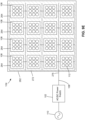
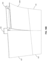
FIG. 1 shows an example of a prior-artLED signage display 10. As shown, theLED signage display 10 comprises one or moreLED display modules 12 having a plurality of LEDs for display, and acabinet 14 for accommodating various electrical components of theLED signage display 10 such a power converter, a central controller, and the like. TheLED display modules 12 are connected to the electrical components in thecabinet 14 via one or more cables (not shown). In this example, theLED display module 12 is physically coupled to thecabinet 14. However, those skilled in the art will appreciate that, in some prior-art LED signage displays 10, theLED display modules 12 may be physically separated from thecabinet 14. -
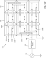
FIG. 2A is a schematic diagram of the commonlyavailable LED signage 10. As shown, theLED display module 12 of theLED signage 10 is electrically connected to apower converter 18 and acentral controller 20 in thecabinet 14 via one ormore cables power converter 18 and acentral controller 20 are physically separated from theLED display module 12 and are electrically connected thereto via thecables - The
LED display module 12 comprises one ormore LED drivers 22 driving a plurality ofLEDs 24 which are usually arranged in a matrix form having one or more rows and one or more columns. EachLED 24 may be a single-color LED that only emits a single-color light such as a red, green, or blue light, or a multi-color LED such as a tri-color LED that can selectively emit multiple colored lights such as red, green, and blue lights. If single-color LEDs are used, the single-color LEDs may be grouped into one or more LED sets with each LED set comprising a red, green, and blue LEDs arranged in proximity with each other, thereby forming a pixel of theLED display module 12. On the other hand, if tri-color LEDs are used, each tri-color LED forms a pixel of theLED display module 12. - The
LED drivers 22 receive electrical power from thepower converter 18 via one or more power wires orcables 16A for powering theLEDs 24. TheLED drivers 22 also receive control signals from thecentral controller 20 via one or more signal wires orcables 16B for regulating the power delivered to theLEDs 24, thereby controlling the lighting of each LED 24 (for example, off, on, lighting intensity, color, and/or the like) for controlling the display of theLED signage 10. Depending on the driving capacity of theLED drivers 22, eachLED driver 22 may be electrically connected to and regulate a subset of theLEDs 24 for example, 4, 8, or 16LEDs 24. - As described before, the
power converter 18 is located in thecabinet 14, physically separated from theLED display module 14 but electrically connected thereto via theelectrical wires power converter 18 comprises an AC/DC converter 26 and a DC/DC converter 28. The AC/DC converter 26 converts the AC electrical power from anexternal power source 30 into high-voltage DC power and outputs the converted high-voltage DC power to the DC/DC converter 28. The DC/DC converter 28 converts the high-voltage DC power received from the AC/DC converter 26 into low-voltage DC power (for example, at about 5V, 7.5V, or the like) suitable for powering theLEDs 24 in theLED display module 12, and outputs the low-voltage DC power to theLED display module 12 via thecable 16A. Therefore, existing LED signage displays 10 have a low-voltage power distribution (for example, 5V) to theirLED display modules 12. - Also referring to
FIG. 2B , each LED display module 12 (and in particular theLED drivers 22 therein) is electrically connected to thecentral controller 20 via thecable 16B such as a ribbon cable. Thecentral controller 20 is functionally connected to one or more computing devices 32 (seeFIG. 2A ) such as a desktop computer, a laptop computer, a smartphone, a tablet, a personal digital assistant (PDA), and the like, via suitable wired or wireless connection for receiving instructions therefrom. In response to the received instructions, thecentral controller 20 sends control signals to theLED drivers 22 to regulates the power delivered to theLEDs 24 of theLED display module 12, thereby controlling the display (for example, off, on, the lighting intensity, color, and the like) of eachLED 24 thereof for controlling the display of theLED signage 10. - There are several challenges and difficulties related to the prior-art digital LED signage displays. For example, due to the fact that a low DC voltage is distributed from the
power converter 18 to theLED display module 12, the electrical current in thepower cable 16A (seeFIG. 2A ) and in other wiring of theLED signage display 10 is significantly large (as the power consumption of theLED signage display 10 is constant), thereby causing substantial amounts of energy losses in the form of heat. Therefore, a prior-art digital LED signage display usually requires multiple fans and/or large heat-sinks for heat dissipation, and consequently requires an effective thermal management system. The large amount of generated heat is also a risk to safety and reliable operation of digital LED signage displays. - Moreover, using fans or rotational parts for the digital LED signage display significantly reduces its reliability since the rotational parts are usually the points of failure in these products.
- As each
LED driver 22 is connected to thecentral controller 20 via thecable 16B (for example a ribbon cable), a large digitalLED signage display 10 generally requires one ormore ribbon cables 16B having a large number of wires therein, which makes the digital LED signage display 10 expensive and unreliable since there is a high risk that the wires in ribbon cables may get disconnected and/or damaged over time, particularly in outdoor applications. Moreover, these ribbon cables are usually points of failure for digital LED signage displays. - As all above-described components are received in the
cabinet 14, a prior-art LED signage display is usually bulky and heavy, and therefore, difficult to install and handle. Lifting or crane equipment is often required for installation of a prior-art LED signage display. -
WO 2009/029197 A1 andUS 2009/0146918 A1 disclose a flexible LED display module comprising a plurality of LED display submodules, each LED submodule comprising a plurality of LEDs, and a plurality of flexible electrical connectors for electrically interconnecting the plurality of LED display submodules, wherein each LED display submodule comprises an enclosure having a frustum shape with a front-side corresponding to the front side of the flexible LED display module, a sidewall, and a rear wall coupled to the sidewall. - The present invention provides a LED display module as defined in
claim 1. - In some embodiments, each LED display submodule may comprise 9 LEDs arranged in a 3-by-3 matrix.
- In some embodiments, the flexible coupling structure comprises a hinge.
- In some embodiments, at least one of the plurality of flexible electrical-connectors is removably connectable to two of the plurality of LED display submodules.
- In some embodiments, at least two of the plurality of LED display submodules may comprise a first electrically-conductive coupling structure. At least one of the plurality of flexible electrical-connectors comprises a second electrically-conductive coupling structure for electrically and mechanically engaging the first electrically-conductive coupling structure.
- In some embodiments, the first electrically-conductive coupling structure may comprise a set of electrically-conductive recesses. The second electrically-conductive coupling structure may comprise at least two sets of electrically-conductive extrusions, wherein each set of extrusions is electrically and mechanically engageable with the set of electrically-conductive recesses.
- In some embodiments, at least one of the plurality of flexible electrical-connectors may comprise two halves flexibly coupled together, wherein the two halves are made of a rigid material.
- In some embodiments, the at least one of the plurality of flexible electrical-connectors may comprise at least one screw hole on each of the two halves for mounting the flexible electrical-connector to a surface.
- In some embodiments, at least one of the plurality of flexible electrical-connectors may comprise a mounting structure for mounting the flexible electrical-connector to a surface.
- In some embodiments, the mounting structure may comprise at least two screw holes.
- In some embodiments, the LED display module may further comprise at least one rigid attachment structure for attaching the LED display module to a surface.
- In some embodiments, at least one of the plurality of flexible electrical-connectors may comprise a flexible Printed Circuit Board (PCB).
- In some embodiments, at least one of the plurality of flexible electrical-connectors is a flexible and electrically conductive strip.
- In some embodiments, the LED display module further may comprise a flexible housing structure, wherein the flexible housing structure comprises a plurality of cells for receiving the plurality of LED display submodules. The plurality of flexible electrical conductors may be embedded in the flexible housing structure.
- In some embodiments, each cell may comprise a plurality of electrical terminals connected to the plurality of flexible electrical conductors and configured for electrically connection with the LED display submodule received in the cell.
- In some embodiments, the plurality of electrical terminals of each cell may comprise at least a first set of electrical terminals for transmitting electrical power.
- In some embodiments, the plurality of electrical terminals of each cell further may comprise at least a second set of electrical terminals for transmitting data or control signals.
- In some embodiments, the plurality of LED display submodules have a same size.
- In some embodiments, at least some of the plurality of LED display submodules have different sizes.
- According to one aspect of the present invention, a LED apparatus is provided which comprises: one or more LED display modules as defined in
claim 1 and one or more set of attachment structures for attaching the one or more LED display modules to a surface, each attachment structure comprising at least one second coupling structure for engaging the first coupling structure. - In some embodiments, each of the one or more set of attachment structures may comprise a mounting structure for mounting the attachment structure to a surface.
- In some embodiments, the mounting structure may comprise at least one screw hole.
- In some embodiments, the at least one first coupling structure of each LED display module may comprise four first coupling structures located at four corners of the LED display module.
- In some embodiments, the one or more LED display modules may comprise a plurality of LED display modules arranged in a matrix manner. The one or more set of attachment structures may comprise at least one first attachment structure configured for coupling two neighboring LED display modules and for attaching the two neighboring LED display modules to a surface.
- In some embodiments, each first attachment structure may comprise two halves flexibly coupled together; wherein each half is made of a rigid material and comprises one of the second coupling structures.
- In some embodiments, the first attachment structure is configured for electrically connecting the two neighboring LED display modules.
- In some embodiments, the first attachment structure comprises a flexible PCB.
- In some embodiments, the first attachment structure may comprise a plurality of first electrical terminals for electrically connecting the two neighboring LED display modules.
- In some embodiments, the plurality of first electrical terminals may comprise at least a first set of first electrical terminals for transmitting electrical power.
- In some embodiments, the plurality of first electrical terminals of each cell may further comprise at least a second set of first electrical terminals for transmitting data or control signals.
- In some embodiments, each LED display module may comprise a flexible housing structure; and the flexible housing structure comprises: a plurality of cells for receiving a plurality of LED display submodules, each LED display submodule comprising a portion of the plurality of LEDs, and a plurality of flexible electrical conductors embedded in the flexible housing structure.
- In some embodiments, each cell may comprise a plurality of second electrical terminals connected to the plurality of flexible electrical conductors and configured for electrically connection with the LED display submodule received in the cell.
- In some embodiments, the plurality of electrical terminals of each cell may comprise at least a first set of second electrical terminals for transmitting electrical power.
- In some embodiments, the plurality of electrical terminals of each cell may further comprise at least a second set of second electrical terminals for transmitting data or control signals.
- In some embodiments, the plurality of LED display submodules have a same size.
- In some embodiments, at least some of the plurality of LED display submodules have different sizes.
- The embodiments of the present invention will now be described with reference to the following figures, in which identical reference numerals in different figures indicate identical elements and in which:
-
FIG. 1 is a side view of a prior-art LED signage display; -
FIG. 2A is a schematic block diagram of the prior-art digital LED signage display shown inFIG. 1 ; -
FIG. 2B is a schematic block diagram showing an example of a central controller connected to one or more LED display modules via a plurality of wires in the prior-art digital LED signage display shown inFIG. 1 ; -
FIG. 3 is a simplified schematic block diagram of an LED display system having an LED signage display, according to some embodiments of the present invention; -
FIG. 4A is a schematic front view of an LED display module shown inFIG. 3 , wherein the LED display submodule at the upper-right corner thereof is shown separated from other LED display submodules for clearer illustration of the submodule; -
FIG. 4B is a schematic perspective view of an LED display module shown inFIG. 3 , showing the rear side thereof; -
FIG. 4C is a schematic perspective view of an LED display module shown inFIG. 3 , showing the front side thereof; -
FIG. 5A is a front view of an LED display submodule shown inFIG. 4A , the LED display submodule comprising nine (9) tri-color LEDs; -
FIG. 5B is a front view of an LED display submodule shown inFIG. 4A , the LED display submodule comprising nine (9) sets of LEDs, each set comprising three single-color LEDs (Red, Green and Blue), and forming a pixel of the LED display submodule; -
FIG. 6A is a cross-sectional view of an LED display submodule having a plurality of multi-color LEDs; -
FIG. 6B is a cross-sectional view of the LED display submodule shown inFIG. 6A ; -
FIG. 7 is a perspective view of a Printed Circuit Board (PCB) of the LED display submodule shown inFIG. 6A ; -
FIG. 8 is a cross-sectional view of two LED display submodules coupled together for forming an LED display module, according to some embodiments of the present invention; -
FIG. 9A is a schematic cross-sectional view of a flexible housing structure of an LED display module, according to an example not forming part of the present invention, the flexible housing structure having cells for receiving and mounted therein LED display submodules; -
FIG. 9B is a schematic cross-sectional view of an enlarged portion of the flexible housing structure shown inFIG. 9A ; -
FIG. 9C is a schematic cross-sectional view of an LED display submodule for installation in a cell of the flexible housing structure shown inFIG. 9A ; -
FIG. 9D is a schematic cross-sectional view of an enlarged portion of the flexible housing structure (shown inFIG. 9A ) with an LED display submodule (shown inFIG. 9C ) installed therein; -
FIG. 9E is a schematic cross-sectional view of a flexible LED display module having a flexible housing structure (shown inFIG. 9A ) with a plurality of LED display submodules (shown inFIG. 9C ) installed therein; -
FIG. 10A is a schematic perspective view of an LED display submodule which may be used in the LED display module according to the present invention; -
FIG. 10B is a schematic top view of the LED display submodule shown inFIG. 10A ; -
FIG. 10C shows two LED display submodules (shown inFIG. 10A ) coupled together; -
FIG. 10D shows a pair of conductive strips for electrically connecting neighboring LED display submodules (shown inFIG. 10A ) in an LED display module; -
FIG. 10E shows two LED display submodules shown inFIG. 10A coupled together and electrically connected together using a pair of conductive strips shown inFIG. 10D ; -
FIG. 10F is a schematic top view of an example flexible LED display module, not forming part of the present invention, having a plurality of LED display submodules shown inFIG. 10A , the plurality of LED display submodules being interconnected using strips shown inFIG. 10D ; -
FIGs. 11A to 11C show a method for connecting LED display modules in an example not forming part of the present invention; -
FIG. 12A is a schematic perspective view of an LED display module shown inFIG. 3 , according to an example not forming part of the present invention; -
FIG. 12B shows two LED display modules shown inFIG. 12A electrically and physically connected using a connector strip; -
FIG. 13A shows another connection method in an example not forming part of the present invention; -
FIG. 13B shows an LED display module having a plurality of electrically connected submodules shown inFIG. 13A ; -
FIGs. 14A to 14F show an LED display module having one or more dual-attachment plates, according to an example not forming part of the present invention; -
FIG. 15 show a single-attachment plate for attaching to an LED display module, according to an example not forming part of the present invention; -
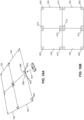
FIG. 16A shows four LED display modules are arranged side-by-side as a 2-by-2 matrix, and a dual-attachment plate is to be placed on to the neighboring corner pockets thereof, according to an example not forming part of the present invention; -
FIG. 16B shows the four LED display modules shown inFIG. 16A being electrically and mechanically connected using a plurality of dual- and single-attachment plates; -
FIGs. 17A to 17E show four LED display modules being electrically interconnected and mounted onto a display stand, according to an example not forming part of the present invention; -
FIGs. 18A and18B show an example of quick replacement of a malfunctioning LED display module, not forming part of the present invention, by removing the malfunctioning LED display module from a display stand, and then attaching a replacement LED display module thereonto; and -
FIGs. 19A to 19C show an example of mounting four LED display modules onto a wall using a plurality of dual- and single-attachment plates, not forming part of the present invention. - The present invention generally relates to a LED display apparatus. In some embodiments, the LED display apparatus is a modularized apparatus with a light weight and a slim profile. In accordance with the present invention, the LED display apparatus comprises one or more flexible LED display modules. The LED display apparatus disclosed herein has many advantages including among others, a slim mechanical structure, no need for multiple cabling to connect each LED display module to a central controller, light weight, compact, high efficiency, and simple heat removal with no rotational components such as fans.
- Turning now to
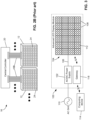
FIG. 3 , an example of the present LED apparatus in the form of a digital LED signage display is shown and is generally identified usingreference numeral 100. As shown, the digitalLED signage display 100 comprises an advancedLED display module 104 formed by a plurality ofLED display submodules 108. EachLED display submodule 108 comprises a plurality ofLEDs 112 drivable at a driving DC voltage such as 5V, 7.5V, 12V, or the like, depending on the implementation. - The digital
LED signage display 100 also comprises a power source or apower supply 102 in the form of an AC/DC power converter in electrical connection with theLED display submodules 108 of the advancedLED display module 104, and agateway 118 in wireless communication with theLED display submodules 108 of theLED display module 104. - The AC/
DC power supply 102 may be mounted at a suitable location of the digitalLED signage display 100 and may be physically separated from the advancedLED display module 104. The AC/DC power supply 102 converts the electrical power of an external AC power source 110 (such as an AC power grid) into a source DC power at a source DC voltage and outputs the source DC power to theLED display submodules 108 via apower cable 106 for powering theLEDs 112. The source DC voltage is generally higher than the driving DC voltage of theLEDs 112. In some embodiments, the source DC voltage of the AC/DC power supply 102 is higher than 7.5V. In some embodiments, the source DC voltage of the AC/DC power supply 102 is higher than 12V. In some embodiments, the source DC voltage of the AC/DC power supply 102 is about 48V. - The AC/
DC power supply 102 outputs a higher source DC voltage compared to the prior-art, low-voltage power distribution LED signage displays. Therefore, the electrical current passing through thepower cable 106 and consequently the energy loss on thepower cable 106 and heat generated therefrom are substantially smaller than that of the prior-art designs that have similar constant power consumption. Furthermore, the high-voltage distribution (for example, 48V) significantly facilitates the integration of solar energy and energy storage (batteries) into the digitalLED signage display 100. In comparison, the prior-art designs require multiple power conversion to implement solar energy and energy storage integration. - Referring again to
FIG. 3 , thegateway 118 is configured for wirelessly communicating with theLED display submodules 108 and with anexternal computing device 114 such as a desktop computer, a laptop computer, a smartphone, a tablet, or the like. Therefore, a user (not shown) of thecomputing device 114 may initiate a command for controlling theLED signage display 100 and wirelessly sends the command to thegateway 118. In response to the command, thegateway 118 then wirelessly communicates with theLED submodules 108 to modulate the lighting of theLEDs 112 thereof. - In various embodiments, the wireless connection between the
gateway 118 and the LED submodules 108 and/or the wireless connection between thegateway 118 and theexternal computing device 114 may be any suitable wireless communication technologies such as WI-FI®, (WI-FI is a registered trademark of the City of Atlanta DBA Hartsfield-Jackson Atlanta International Airport Municipal Corp., Atlanta, GA, USA), BLUETOOTH® (BLUETOOTH is a registered trademark of Bluetooth Sig Inc., Kirkland, WA, USA), ZIGBEE® (ZIGBEE is a registered trademark of ZigBee Alliance Corp., San Ramon, CA, USA), wireless mobile telecommunications technologies (such as GSM, CDMA, LTE, and the like), and/or the like. - As shown in
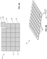
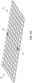
FIGs. 4A to 4C , eachLED display module 104 in these embodiments is a flexible LED display module and comprises a plurality ofLED display submodules 108 coupled to each other in a flexible manner. EachLED display submodule 108 comprises one ormore LEDs 112. Therefore, unlike the prior-art LED signage displays that generally have a planar display surface, the flexibleLED display module 104 may be configured to form anon-planar display surface 116, for example acurved display surface 116 such as shown inFIG. 4C . - In
FIGs. 4A to 4C , theLED display submodules 108 are arranged as a matrix having a plurality of rows and columns. In other embodiments, theLED display submodule 108 may be arranged in different configurations such as in different numbers of rows and columns and/or in different layouts such as triangles, circles, and the like. - In the example shown in
FIG. 4A , eachLED display submodule 108 comprises nine (9) LED pixels (being ninetri-color LEDs 112 or 27 single-color LEDs 112, described in more detail later) arranged in a 3-by-3 matrix which is optimal for this example of an integrated solution based on Applicant's power-loss calculation. However, in other embodiments, anLED display submodule 108 may comprise different numbers ofLEDs 112, and theLEDs 112 may be arranged in different configurations such as in different numbers of rows and columns, and/or in different layouts such as triangles, circles, and the like. - Each
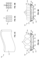
LED display submodule 108 comprises one or more LED pixels. Depending on the types of the LEDs, each LED pixel may comprise onemulti-color LED 112, or a set of three single-color LEDs 112 (Red, Green and Blue) arranged in proximity with each other.FIG. 5A shows anLED display submodule 108 having nine (9)tri-color LEDs 112.FIG. 5B shows anLED display submodule 108 having nine (9) sets ofLEDs 112. Each LED set comprises three single-color LEDs (Red, Green and Blue) forming a pixel of theLED display submodule 108. -
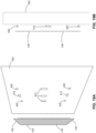
FIG. 6A is a cross-sectional view of anLED display submodule 108 having a plurality ofmulti-color LEDs 112.FIG. 6B is a cross-sectional view of anLED display submodule 108 having a plurality of single-color LEDs 112.FIG. 6B is generally the same asFIG. 6A except that the types and numbers of the LEDs in the two figures are different. - As shown in
FIGs. 6A and 6B , theLED display submodule 108 comprises an enclosure (which may also be referred to as a case) 202. In accordance with the present invention, theenclosure 202 has a frustum shape such as a square frustum and comprises a front opening 204 (corresponding to the front side of the LED display module 104) arearwardly tapering sidewall 206, and arear wall 208 coupled to thesidewall 206. Therefore, thefront opening 204 has a larger area than that of therear wall 208. - The
LED display submodule 108 also comprises a Printed Circuit Board (PCB) 222 coupled to theenclosure 202 about thefront opening 204 thereof by fastening thePCB 222 onto a plurality ofanchors 226 of theenclosure 202 using a plurality ofmicro screws 224. - Although not shown, in this embodiment, the
enclosure 202 is filled with suitable potting material which may comprise for example, a solid or gelatinous compound such as thermo-setting plastics, silicone, epoxy, and/or the like, for encapsulating thePCB 222 and components thereon, and for protecting thePCB 222 and components thereon from physical shocks, moisture, and/or the like. - The
LEDs 112 are coupled to thePCB 222 on thefront side 232 thereof. A plurality of electrical components for modulating and supplying power to theLEDs 112, for example a power integrated circuit (IC)chip 234, resistors/capacitors 236, and the like, are coupled to thePCB 222 on therear side 238 thereof. ThePCB 222 comprises necessary printed conductive strips/wires (not shown) for electrically connecting theLEDs 112, theelectrical components power IC chip 234 receives power from the high-voltage distribution bus (such as 48V), and provides multiple DC outputs to theLEDs 112 in theLED display submodule 108. -
FIG. 7 is a perspective view of thePCB 222, showing therear side 238 of thePCB 222 and theelectrical components FIG. 7 . - In these embodiments, the
enclosure 202 is made of a rigid material such as steel, plastic, hard rubber, and the like, and therefore theenclosure 202 itself is non-flexible or only slightly flexible without damaging the components therein. However, theLED display submodules 108 are flexibly coupled to each other such that the assembledLED display module 104 is flexible and may be configured to have acurved display surface 116. -
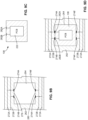
FIG. 8 shows how theLED display submodules 108 are coupled together in accordance with the present invention to form a flexibleLED display module 104. As shown, twoLED display submodules edges respective sidewalls LED display submodules flexible coupling structure 244 such as glue, hinge, clip, strip, and/or the like, to allow the twoLED display submodules flexible coupling structure 244. - In an example not forming part of the present invention as shown in
FIG. 9A , theLED display module 104 comprises aflexible housing structure 262 made of a flexible material such as flexible rubber, and comprises a plurality of cells 264 (such as openings) matching the shape of theLED display submodules 108. Theflexible housing structure 262 also comprises a plurality of interconnected, flexibleelectrical conductors 272 such as conductive wires embedded therein and flexible therewith. The interconnectedelectrical conductors 272 are connected to alead conductor 276 for electrically connecting to a power source. - Each
electrical conductor 272 comprises at least two conductive wires. For example, eachelectrical conductor 272 comprises a pair of conductive wires, with one wire configured as a ground wire and the other as a 48V power wire for powering theLED display submodules 108. - Each
cell 264 comprises at least one set ofelectrical terminals 274 located on and exposed from the walls thereof, and connected to theelectrical conductors 272 in such a manner that the electrical terminal sets 274 are electrically connected in parallel through theelectrical conductors 272. For example, inFIG. 9A , eachcell 264 comprises two sets ofelectrical terminals 274 located on and exposed from the opposite walls thereof. Both sets ofelectrical terminals 274 are connected to theelectrical conductors 272. -
FIG. 9B shows an enlarged portion of theflexible housing structure 262. As shown, eachelectrical line 272 comprise two wires including afirst wire 272A as the 48V power wire and asecond wire 272B as the ground wire. Correspondingly, eachcell 264 comprises two pairs of terminals (274A, 274B) and (274A', 274B') located on and exposed fromopposite walls terminals 48V power wire 272A, and theterminals ground wire 272B. - As shown in
FIG. 9C , eachLED display submodule 108 comprises a pair ofelectrical terminals PCB 222 thereof. Theelectrical terminals - As shown in
FIG. 9D , anLED display submodule 108 may be fit into acell 264 of theflexible housing structure 262. Then, thepower input terminal 282A of theLED display submodule 108 is in electrical contact with the power-line terminal 274A of thecell 264, and theground terminal 282B of theLED display submodule 108 is in electrical contact with theground terminal 274B of thecell 264. In this way, eachLED display submodule 108, after fitting into acell 264, is electrically connected to thelead conductor 276. - As shown in
FIG. 9E , after fitting allLED display submodules 108 into thecells 264 of theflexible housing structure 262, anLED display module 104 is then assembled. TheLED display module 104 may be connected to anexternal power source 110 by connecting thelead conductor 276 to the AC/DC power supply 102 via thecable 106, and connecting the AC/DC power supply 102 to theexternal power source 110. - In some alternative embodiments, the
LED display submodules 108 are electrically connected using conductive strips, for example, ribbon cables, with releasable fasteners such as snap fasteners. This connection mechanism is suitable for both theLED display module 104 without a flexible housing structure (for example, that shown inFIG. 8 ) and theLED display module 104 with a flexible housing structure (for example, that shown inFIG. 9E but without the embedded electrical conductors). -
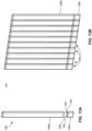
FIGs. 10A and 10B are a schematic perspective view and a schematic plan view, respectively, of anLED display submodule 108 which may be used in the LED display module according to the present invention. As shown, theLED display submodule 108 comprises an electrically-conductive, mechanical coupling structure (302A, 302B) in the form of two pairs of electrical conductive recesses on therear wall 208 of theenclosure 202 located about the opposite edges of therear wall 208 for mechanically and electrically coupling with flexible electrical-connectors such as flexible and electricallyconductive strips FIG. 10D , described in more detail later). The tworecesses 302A (also denoted as the power-input recesses) are electrically connected via aconductive link 304A within theenclosure 202, and are configured for electrically connecting to the PCB (not shown) as the 48V power-input. The other tworecesses 302B (also denoted as the ground recesses) are electrically connected via aconductive link 304B within theenclosure 202, and are configured for electrically connecting to the PCB (not shown) as the ground. - As described above, a plurality of
LED display submodules 108 may be coupled together in a side-by-side manner to form anLED display module 104. In various embodiments, the plurality ofLED display submodules 108 may be coupled together without using a housing structure, or with the use of flexible housing structure. The method described in the follows is based on coupling the plurality ofLED display submodules 108 without using a housing structure. However, the same method is also readily applicable for coupling a plurality ofLED display submodules 108 using a flexible housing structure. -
FIG. 10C shows two LED display submodules 108-1 and 108-2 coupled together. The distance between the power-input recesses 302A-1 and 302A-2 about the neighboring sides of the LED display submodules 108-1 and 108-2 is L1, and the distance between the ground recesses 302B-1 and 302B-2 about the neighboring sides of the LED display submodules 108-1 and 108-2 is L2. - As shown in
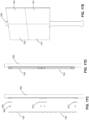
FIG. 10D , a pair of flexible and electricallyconductive strips strip mechanical coupling structure 308 in the form of a pair of conductive extrusions on the opposite sides thereon and electrically connected by the flexible conductive-strip coupling structure LED display submodule 108. - In particular, the
extrusion 308 of the flexible conductive-strip recess LED display submodule 108 to form a snap fastener. The lengths of the flexible conductive-strips strip conductive recesses - As shown in
FIG. 10E , the flexible conductive-strip 306A may be coupled to the two LED display submodules 108-1 and 108-2, and electrically connect therecesses 302A-1 and 302A-2 by respectively snapping and locking theopposite extrusions 308 into therecesses 302A-1 and 302A-2. Similarly, the flexible conductive-strip 306B may be coupled to the two LED display submodules 108-1 and 108-2, and electrically connect therecesses 302B-1 and 302B-2 by respectively snapping and locking theopposite extrusions 308 into therecesses 302B-1 and 302B-2. -
FIG. 10F shows an example flexibleLED display module 104, not forming part of the present invention, formed by a plurality ofLED display submodules 108. The plurality ofLED display submodules 108 are interconnected by using a plurality of flexible conductive-strips external power source 110 via thecable 106 and the AC/DC power supply 102. - In some alternative embodiments where a
flexible housing structure 262 is used for accommodating and assemblingLED display submodules 108, the above-described embeddedelectrical conductors 272 and flexible conductive-strips LED display submodules 108. - For example, in some embodiments, the
flexible housing structure 262 comprises a set ofelectrical conductors 272 embedded therein for interconnecting a first portion of theLED display submodules 108, and flexible conductive-strips LED display submodules 108. - In an example not forming part of the present invention, the
LED display module 104 is formed as shown inFIG. 9E . In other words, allLED display submodules 108 are installed onto theflexible housing structure 262 and are interconnected by theelectrical conductors 272 embedded therein. As those skilled in the art will appreciate, the embeddedelectrical conductors 272 may wear out and break over time during use. Therefore, in these embodiments, a plurality of flexible conductive-strips LED display submodules 108 in the event that the embeddedelectrical conductors 272 that connect theseLED display submodules 108 are broken. -
FIGs. 11A to 11C show a method for connectingLED display modules 104 in an example not forming part of the present invention. - As shown in
FIG. 11A , anLED display module 104 comprises fourconnector submodules 108A at the four corners thereof. Each corner submodule 108A comprises a pair of electricallyconductive recesses 350.FIG. 11B is a perspective view of a flexible connector orconductive strip 352. Theconductive strip 352 comprises two pairs of conductive extrusions (354A, 354B) and (354A', 354B') on the opposite sides thereof, respectively, for electrically conductively coupling to therecesses 350 of theLED display module 104. Theextrusions electrical strip 356A, and theextrusions electrical strip 356B. As shown inFIG. 11C , twoLED display modules conductive strips 352. -
FIG. 12A shows anLED display module 104 in an example not forming part of the present invention. - The
LED display module 104 is similar to that shown inFIG. 11A except that in these embodiments, the fourconnector submodules 362 at the four corners of theLED display module 104 have a reduced thickness. Similar to theconnector submodules 108A shown inFIG. 11A , eachconnector submodule 362 shown inFIG. 12A comprises a pair of electricallyconductive recesses 350. - As shown in
FIG. 12B , twoLED display modules 104 may be electrically connected by usingconductive strips 352 to connect neighboringconnector submodules 362 in a manner similar to that shown inFIG. 11C . As theconnector submodules 362 has reduced thickness, theconductive strips 352 would not extrude from the rear side of theLED display module 104 when attached to theconnector submodules 362. - In above embodiments, the
LED display submodules 108 generally have a same shape. In some alternative embodiments, theLED display submodules 108 may have different shapes. - For example, in an example not forming part of the present invention as shown in
FIGs. 13A and 13B , theLED display module 104 may be formed by two types ofLED display submodules LED display submodule 108A has substantially same length and width, and theLED display submodule 108B has a length much longer than the width thereof. - As shown in
FIG. 13A , thesubmodule 108A comprises a pair of electricallyconductive terminals 382 extruding from aside 384 thereof. Correspondingly, thesubmodule 108B comprises a pair of electrically conductive channels or recesses (not shown) on acorresponding side 388 thereof for receiving theterminals 382 of thesubmodule 108A for electrically connecting the twosubmodules submodules LED display module 104. - As shown in
FIG. 13B , a plurality ofmodule columns 386 are assembled together using suitable fasteners such as glue, screws, nails, strips, and/or the like, to form theLED display module 104. Although not shown, the plurality ofmodule columns 386 may be electrically connected using conductive strips as described above. -
FIGs. 14A to 14F show anLED display module 104 in an example not forming part of the present invention. - As shown in
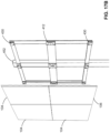
FIGs. 14A and 14B , theLED display module 104 comprises aflexible housing structure 262 made of a suitable flexible material such as flexible rubber. As described before, theflexible housing structure 262 comprises a plurality of cells or pockets 264, acentral pocket 266, and fourcorner pockets 268 at the four corners thereof, for receiving therein a plurality of LED display submodules (not shown). Thecentral pocket 266 may also receive therein other necessary circuits and components. Eachcorner pocket 268 comprises a pair of rearwardly extending,cylindrical extrusions 404. Eachextrusion 404 comprises a magnet as an attachment means (described later). As shown inFIG. 14F , eachextrusion 404 also comprises one or more electrical terminals and necessary wiring for electrically connecting the electrical terminals to the LED display submodule thereof. One of the pair of theextrusions 404 is used for data communication of LED display submodule, and the other one of theextrusions 404 is used for power input to the LED display submodule. - As shown in
FIGs. 14C and14D , theLED display module 104 also comprises one or more dual-attachment plates 412. As shown, the dual-attachment plate 412 comprises twohalves half recesses 414 for receiving the pair ofextrusions 404 of acorner pocket 268. Eachrecess 414 comprises a magnet of an opposite pole of thecorresponding extrusion 404 of thecorner pocket 268, and also comprises electrical terminals and necessary wiring for electrically connecting the electrical terminals to a flexible PCB or a ribbon cable 418 extending across the first andsecond halves attachment plate 412 comprises a mounting structure in the form of twoscrew holes 416 on the twohalves attachment plate 412 to a surface of a mounting equipment such as a display stand (not shown) using a suitable fastener such as a screw or a nail. - As shown in
FIGs. 14E and 14F , and as indicated by thearrows 422, twoLED display modules 104 may be arranged side-by-side, and a dual-attachment plate 412 is placed onto the neighboring corner pockets 268 of the twoLED display modules 104 such that eachextrusion 404 is received in acorresponding recess 414. The magnetic force of the opposite-pole magnets in theextrusion 404 and therecess 414 firmly couples the dual-attachment plate 412 to the twoLED display modules 104, and the electrical terminals therein are in electrical contact with teach other. Thus, the dual-attachment plate 412 also acts as an electrical connector connecting the circuits of the twoLED display modules 104. - In an example not forming part of the present invention, the
LED display module 104 further comprises anattachment structure 430 in the form of a single-attachment plate as shown inFIG. 15 . The single-attachment plate 430 is similar to the first or thesecond half attachment plate 412. That is, the single-attachment plate 430 is made of a suitable rigid material such as rigid rubber, and comprises a pair ofrecesses 414 for receiving the pair ofextrusions 404 of acorner pocket 268. Eachrecess 414 comprises a magnet of an opposite pole of thecorresponding extrusion 404 of thecorner pocket 268, and may also comprise electrical terminals for connecting to external cables such as a data cable and a power cable. In these examples, the single-attachment plate 430 also comprises a mounting structure in the form of ascrew hole 416 for attaching the dual-attachment plate 412 to a surface of a mounting equipment such as a display stand (not shown) using a suitable fastener such as a screw or a nail. -
FIG. 16A shows fourLED display modules 104 arranged side-by-side as a 2-by-2 matrix. A dual-attachment plate 412 is to be placed on to the neighboring corner pockets 268 thereof.FIG. 16B shows the fourLED display modules 104 being electrically and mechanically connected using a plurality of dual- and single-attachment plates - By using the dual-attachment and single-
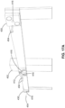
attachment plates LED display modules 104 may be mounted to a suitable mounting structure. For example,FIGs. 17A to 17E show fourLED display modules 104 being electrically interconnected and mounted onto adisplay stand 452. As shown inFIG. 17A , a plurality of dual-attachment and single-attachment plates screws 454 through the screw holes 416 of the dual-attachment and single-attachment plates display stand 452. - As shown in
FIG. 17B , fourLED display modules 104 are then attached to the dual-attachment and single-attachment plates display stand 452. -
FIG. 17C is a side view of theLED display modules 104 and thedisplay stand 452, showing how theLED display modules 104 are removably mounted onto thedisplay stand 452.FIG. 17D is a side view of the LED display modules mounted onto thedisplay stand 452.FIG. 17E is a perspective view of theLED display modules 104 mounted onto thedisplay stand 452. - The above described electrical interconnection and mounting method has an advantage of easy and quick placement of LED display modules.
FIGs. 18A and18B show an example. As shown inFIG. 18A , anLED display module 104E is malfunctioning and need to be replaced. Therefore, one may apply an outward force to theLED display module 104E to overcome to magnetic force between theLED display module 104E and the dual- and single-attachment plates LED display module 104E from thedisplay stand 452. The flexibility of theLED display module 104E facilitates the removal of theLED display module 104E. - As shown in
FIG. 18B , one may then attach a replacementLED display module 104R to the dual-attachment and single-attachment plates LED display module 104R onto thedisplay stand 452. The flexibility of theLED display module 104R facilitates the attaching of theLED display module 104R. - In an example not forming part of the present invention, one or more
LED display modules 104 may be mounted onto other mounting equipment using dual-attachment and single-attachment plates FIGs. 19A to 19C show an example of mounting fourLED display modules 104 onto awall 502 using a plurality of dual-attachment and single-attachment plates - Although embodiments have been described above with reference to the accompanying drawings, those of skill in the art will appreciate that variations and modifications may be made without departing from the scope of the present invention as defined by the appended claims.
Claims (9)
- A Light-Emitting Diode (LED) display module (104) comprising:a plurality of LED display submodules (108), each LED display submodule comprising one or more LEDs (112); anda plurality of flexible electrical-connectors (272, 306A, 306B) for electrically interconnecting the plurality of LED display submodules;wherein each LED display submodule comprises an enclosure (202) in a frustum shape and having a front-side opening (204) corresponding to the front side of the LED display module, and a sidewall (206) rearwardly tapering from said front side opening thereof to a rear wall (208), the rear wall being coupled to the sidewall; andwherein the plurality of LED display submodules (108A, 108B) are flexibly coupled to each other side-by-side at neighboring edges (242A, 242B) of the sidewalls (206A, 206B) of the respective enclosures on the front side thereof via a flexible coupling structure (244) to form a flexible display surface.
- The LED display module (104) of claim 1, wherein at least one of the plurality of flexible electrical-connectors (272, 306A, 306B) comprising two halves flexibly coupled together, the two halves made of a rigid material.
- The LED display module (104) of claim 1, wherein at least one of the plurality of flexible electrical-connectors (306A, 306B) is removably connectable to two of the plurality of LED display submodules (108).
- The LED display module (104) of claim 1, wherein at least two of the plurality of LED display submodules (108) each comprises a first electrically-conductive coupling structure; and wherein at least one of the plurality of flexible electrical-connectors comprises a second electrically-conductive coupling structure for electrically and mechanically engaging the first electrically-conductive coupling structure.
- The LED display module (104) of claim 4, wherein the first electrically-conductive coupling structure comprises a set of electrically-conductive recesses (302A, 302B); and wherein the second electrically-conductive coupling structure comprises at least two sets of electrically-conductive extrusions (308), each set of extrusions electrically and mechanically engageable with the set of electrically-conductive recesses.
- The LED display module (104) of any one of claims 1 to 5, wherein at least one of the plurality of flexible electrical-connectors comprises a flexible Printed Circuit Board (222) or a flexible and electrically conductive strip (306A, 306B).
- The LED display module (104) of claim 1 further comprising a flexible housing structure (262), the flexible housing structure comprising a plurality of cell (264) forming the enclosures (202) of the plurality of LED display submodules (108), wherein the plurality of flexible electrical-connectors comprises a plurality of flexible electrical conductors (272) embedded in the flexible housing structure.
- The LED display module (104) of claim 7, wherein each cell (264) comprises a plurality of electrical terminals (274) connected to the plurality of flexible electrical conductors (272) and configured for electrical connection with the LED display submodule (108) received in the cell; and wherein the plurality of electrical terminals of each cell comprises at least a first set of electrical terminals (274A, 274B, 274A', 274B') for transmitting electrical power and a second set of electrical terminals for transmitting data or control signals.
- The LED display module (104) of claim 7, wherein the flexible housing structure (262) is made of a flexible rubber.
Applications Claiming Priority (2)
| Application Number | Priority Date | Filing Date | Title |
|---|---|---|---|
| US201762475055P | 2017-03-22 | 2017-03-22 | |
| PCT/CA2018/050347 WO2018170599A1 (en) | 2017-03-22 | 2018-03-22 | Apparatus having a flexible led display module and a method of employing same |
Publications (4)
| Publication Number | Publication Date |
|---|---|
| EP3602531A1 EP3602531A1 (en) | 2020-02-05 |
| EP3602531A4 EP3602531A4 (en) | 2021-08-25 |
| EP3602531C0 EP3602531C0 (en) | 2023-06-07 |
| EP3602531B1 true EP3602531B1 (en) | 2023-06-07 |
Family
ID=63584515
Family Applications (1)
| Application Number | Title | Priority Date | Filing Date |
|---|---|---|---|
| EP18772216.0A Active EP3602531B1 (en) | 2017-03-22 | 2018-03-22 | Flexible led display module |
Country Status (8)
| Country | Link |
|---|---|
| US (1) | US11062628B2 (en) |
| EP (1) | EP3602531B1 (en) |
| JP (1) | JP7282733B2 (en) |
| KR (1) | KR102472603B1 (en) |
| CN (1) | CN110651318B (en) |
| CA (1) | CA3031197C (en) |
| SG (1) | SG11201908765RA (en) |
| WO (1) | WO2018170599A1 (en) |
Families Citing this family (7)
| Publication number | Priority date | Publication date | Assignee | Title |
|---|---|---|---|---|
| DE102017113573A1 (en) * | 2017-06-20 | 2018-12-20 | Osram Opto Semiconductors Gmbh | Arrangement with a plurality of lighting modules and method for producing an arrangement with a plurality of lighting modules |
| CN110197629A (en) * | 2019-07-04 | 2019-09-03 | 深圳市齐普光电子股份有限公司 | A kind of Modularized splice LED display |
| KR20210015488A (en) * | 2019-08-02 | 2021-02-10 | 삼성전자주식회사 | Cabinet for LED display apparatus, apparatus for manufacturing the same, and method for manufacturing the same |
| CN111785216A (en) * | 2020-07-03 | 2020-10-16 | 业成科技(成都)有限公司 | LED array arrangement scheme generation method and device and liquid crystal display module |
| KR20220030471A (en) * | 2020-09-01 | 2022-03-11 | 삼성디스플레이 주식회사 | Display system and method of driving the same |
| US11769759B1 (en) * | 2021-05-04 | 2023-09-26 | Bejan E. Amini | Mounting device for LED panels |
| US20230417387A1 (en) * | 2022-06-24 | 2023-12-28 | Lumileds Llc | Flexible three dimensional display assembly for electric vehicles |
Family Cites Families (27)
| Publication number | Priority date | Publication date | Assignee | Title |
|---|---|---|---|---|
| JPH07199828A (en) * | 1993-12-28 | 1995-08-04 | Rohm Co Ltd | Connecting structure between electronic part units |
| JP2001282142A (en) | 2000-03-31 | 2001-10-12 | Matsushita Electric Ind Co Ltd | Display device |
| JP2006106046A (en) | 2004-09-30 | 2006-04-20 | Toshiba Transport Eng Inc | Connector and video display apparatus |
| US8344410B2 (en) * | 2004-10-14 | 2013-01-01 | Daktronics, Inc. | Flexible pixel element and signal distribution means |
| JP2006322968A (en) | 2005-05-17 | 2006-11-30 | Toranto:Kk | Display apparatus |
| US8599108B2 (en) * | 2007-12-11 | 2013-12-03 | Adti Media, Llc140 | Large scale LED display |
| US9013367B2 (en) * | 2008-01-04 | 2015-04-21 | Nanolumens Acquisition Inc. | Flexible display |
| CN101198216A (en) * | 2008-01-07 | 2008-06-11 | 史杰 | Flexible circuit board of LED illumination array |
| CN101345006A (en) * | 2008-08-27 | 2009-01-14 | 深圳市大眼界光电科技有限公司 | Patch type LED outdoor display screen |
| CN102246606B (en) | 2008-12-09 | 2016-08-17 | 皇家飞利浦电子股份有限公司 | Flexible module assembly |
| CN101640008A (en) * | 2009-05-08 | 2010-02-03 | 北京中庆微数字设备开发有限公司 | Foldable LED display screen |
| CN202217456U (en) * | 2011-08-12 | 2012-05-09 | 广州市夜空彩虹光电科技有限公司 | Light emitting diode (LED) flexible hung display screen |
| US8929085B2 (en) * | 2011-09-30 | 2015-01-06 | Apple Inc. | Flexible electronic devices |
| CN102646373B (en) * | 2012-04-23 | 2013-10-23 | 吴小刚 | LED display module with quick mounting-demounting structure |
| CN102930789B (en) | 2012-11-28 | 2014-12-31 | 吴小刚 | LED (light-emitting diode) display screen with bending and folding functions |
| CN104505003B (en) * | 2013-01-09 | 2017-08-18 | 深圳市维世科技有限公司 | A kind of flexible LED screen that can freely fold |
| US8824124B1 (en) * | 2013-03-16 | 2014-09-02 | ADTI Media, LLC | Modular wire harness arrangements and methods of using same for backside to frontside power and data distribution safety schemes |
| CN203232654U (en) * | 2013-04-28 | 2013-10-09 | 佛山鼎辉光电科技有限公司 | Flexible LED display screen |
| EP3143323B1 (en) * | 2014-04-29 | 2019-10-09 | Cooledge Lighting, Inc. | Modular led lighting systems |
| JP2017529573A (en) * | 2014-09-02 | 2017-10-05 | ウェイヴィーン・インコーポレイテッド | Bulletin board or other large display with artwork illuminated by LED backlight array |
| GB2536191A (en) * | 2015-01-05 | 2016-09-14 | Barco Nv | Flexible display tile and method of producing same |
| CN204463737U (en) * | 2015-03-10 | 2015-07-08 | 宁波蓝科电子工程有限公司 | A kind of Novel LED display screen |
| US9477438B1 (en) * | 2015-09-25 | 2016-10-25 | Revolution Display, Llc | Devices for creating mosaicked display systems, and display mosaic systems comprising same |
| CN205621369U (en) * | 2015-12-29 | 2016-10-05 | 梅州市腾安电子科技有限公司 | Modular LED display screen |
| JP3203324U (en) | 2016-01-12 | 2016-03-24 | ニッシン・トーア株式会社 | Flexible light emitting device |
| US20180373293A1 (en) * | 2017-06-21 | 2018-12-27 | Newtonoid Technologies, L.L.C. | Textile display system and method |
| US11296063B2 (en) * | 2018-11-20 | 2022-04-05 | Lumens Co., Ltd. | Flexible LED display with processor under a folded edge portion |
-
2018
- 2018-03-22 WO PCT/CA2018/050347 patent/WO2018170599A1/en unknown
- 2018-03-22 CA CA3031197A patent/CA3031197C/en active Active
- 2018-03-22 CN CN201880033296.3A patent/CN110651318B/en active Active
- 2018-03-22 KR KR1020197030851A patent/KR102472603B1/en active IP Right Grant
- 2018-03-22 EP EP18772216.0A patent/EP3602531B1/en active Active
- 2018-03-22 US US16/496,334 patent/US11062628B2/en active Active
- 2018-03-22 JP JP2020500934A patent/JP7282733B2/en active Active
- 2018-03-22 SG SG11201908765R patent/SG11201908765RA/en unknown
Also Published As
| Publication number | Publication date |
|---|---|
| JP2020511700A (en) | 2020-04-16 |
| CN110651318A (en) | 2020-01-03 |
| US11062628B2 (en) | 2021-07-13 |
| SG11201908765RA (en) | 2019-10-30 |
| CN110651318B (en) | 2022-06-03 |
| EP3602531C0 (en) | 2023-06-07 |
| KR20190129972A (en) | 2019-11-20 |
| EP3602531A4 (en) | 2021-08-25 |
| CA3031197A1 (en) | 2018-09-27 |
| US20200035134A1 (en) | 2020-01-30 |
| EP3602531A1 (en) | 2020-02-05 |
| JP7282733B2 (en) | 2023-05-29 |
| CA3031197C (en) | 2020-03-10 |
| WO2018170599A1 (en) | 2018-09-27 |
| KR102472603B1 (en) | 2022-11-30 |
Similar Documents
| Publication | Publication Date | Title |
|---|---|---|
| EP3602531B1 (en) | Flexible led display module | |
| US20120019490A1 (en) | Modular led display structure with connecting edge banding to connect each other | |
| US9696019B2 (en) | LED lighting structure | |
| US20130322082A1 (en) | Modular light emitting diode (led) lighting fixtures | |
| CN208368053U (en) | display module, display screen and display system | |
| WO2011133813A2 (en) | Expandable led board architecture | |
| WO2009008964A2 (en) | Wireless controlled light emitting assembly | |
| US20120187856A1 (en) | Package structure of full-color led integrated with driving mechanism and current limiting elements | |
| US7467888B2 (en) | Quick change power supply | |
| CN208077542U (en) | display module, display screen and display system | |
| US20200211446A1 (en) | Display Panels with Embedded Control System | |
| CN110710331B (en) | LED apparatus with integrated power supply and method employing the same | |
| EP2837877B1 (en) | Easily expandable indoors led lighting device | |
| US9072135B2 (en) | Systems and methods for modular and configurable driver system for LED lighting devices | |
| US20140159579A1 (en) | Lighting module and lighting apparatus using lighting module | |
| CA3069163C (en) | Led apparatus having one or more communication units and a method of employing same | |
| CN212108158U (en) | Lamp fitting | |
| KR101011970B1 (en) | A Moduling Direct Current Power Source Supply Unit for LED Lamp | |
| CN220022226U (en) | Power supply system of LED display screen and LED display screen | |
| CN210986520U (en) | Split combined power driver | |
| CN211656464U (en) | Lamp and control circuit thereof | |
| KR20130103648A (en) | Led module and driving method thereof |
Legal Events
| Date | Code | Title | Description |
|---|---|---|---|
| STAA | Information on the status of an ep patent application or granted ep patent |
Free format text: STATUS: THE INTERNATIONAL PUBLICATION HAS BEEN MADE |
|
| PUAI | Public reference made under article 153(3) epc to a published international application that has entered the european phase |
Free format text: ORIGINAL CODE: 0009012 |
|
| STAA | Information on the status of an ep patent application or granted ep patent |
Free format text: STATUS: REQUEST FOR EXAMINATION WAS MADE |
|
| 17P | Request for examination filed |
Effective date: 20190925 |
|
| AK | Designated contracting states |
Kind code of ref document: A1 Designated state(s): AL AT BE BG CH CY CZ DE DK EE ES FI FR GB GR HR HU IE IS IT LI LT LU LV MC MK MT NL NO PL PT RO RS SE SI SK SM TR |
|
| AX | Request for extension of the european patent |
Extension state: BA ME |
|
| DAV | Request for validation of the european patent (deleted) | ||
| DAX | Request for extension of the european patent (deleted) | ||
| RIC1 | Information provided on ipc code assigned before grant |
Ipc: G09F 9/33 20060101AFI20210416BHEP Ipc: H01L 25/13 20060101ALI20210416BHEP Ipc: H01R 12/77 20110101ALI20210416BHEP Ipc: H01L 25/075 20060101ALI20210416BHEP |
|
| A4 | Supplementary search report drawn up and despatched |
Effective date: 20210728 |
|
| RIC1 | Information provided on ipc code assigned before grant |
Ipc: G09F 9/33 20060101AFI20210722BHEP Ipc: H01L 25/13 20060101ALI20210722BHEP Ipc: H01R 12/77 20110101ALI20210722BHEP Ipc: H01L 25/075 20060101ALI20210722BHEP |
|
| GRAP | Despatch of communication of intention to grant a patent |
Free format text: ORIGINAL CODE: EPIDOSNIGR1 |
|
| STAA | Information on the status of an ep patent application or granted ep patent |
Free format text: STATUS: GRANT OF PATENT IS INTENDED |
|
| INTG | Intention to grant announced |
Effective date: 20220627 |
|
| GRAJ | Information related to disapproval of communication of intention to grant by the applicant or resumption of examination proceedings by the epo deleted |
Free format text: ORIGINAL CODE: EPIDOSDIGR1 |
|
| STAA | Information on the status of an ep patent application or granted ep patent |
Free format text: STATUS: REQUEST FOR EXAMINATION WAS MADE |
|
| INTC | Intention to grant announced (deleted) | ||
| GRAP | Despatch of communication of intention to grant a patent |
Free format text: ORIGINAL CODE: EPIDOSNIGR1 |
|
| STAA | Information on the status of an ep patent application or granted ep patent |
Free format text: STATUS: GRANT OF PATENT IS INTENDED |
|
| INTG | Intention to grant announced |
Effective date: 20221215 |
|
| GRAS | Grant fee paid |
Free format text: ORIGINAL CODE: EPIDOSNIGR3 |
|
| GRAA | (expected) grant |
Free format text: ORIGINAL CODE: 0009210 |
|
| STAA | Information on the status of an ep patent application or granted ep patent |
Free format text: STATUS: THE PATENT HAS BEEN GRANTED |
|
| AK | Designated contracting states |
Kind code of ref document: B1 Designated state(s): AL AT BE BG CH CY CZ DE DK EE ES FI FR GB GR HR HU IE IS IT LI LT LU LV MC MK MT NL NO PL PT RO RS SE SI SK SM TR |
|
| REG | Reference to a national code |
Ref country code: GB Ref legal event code: FG4D |
|
| REG | Reference to a national code |
Ref country code: CH Ref legal event code: EP Ref country code: AT Ref legal event code: REF Ref document number: 1577361 Country of ref document: AT Kind code of ref document: T Effective date: 20230615 |
|
| REG | Reference to a national code |
Ref country code: DE Ref legal event code: R096 Ref document number: 602018051190 Country of ref document: DE |
|
| U01 | Request for unitary effect filed |
Effective date: 20230704 |
|
| U07 | Unitary effect registered |
Designated state(s): AT BE BG DE DK EE FI FR IT LT LU LV MT NL PT SE SI Effective date: 20230712 |
|
| REG | Reference to a national code |
Ref country code: LT Ref legal event code: MG9D |
|
| PG25 | Lapsed in a contracting state [announced via postgrant information from national office to epo] |
Ref country code: NO Free format text: LAPSE BECAUSE OF FAILURE TO SUBMIT A TRANSLATION OF THE DESCRIPTION OR TO PAY THE FEE WITHIN THE PRESCRIBED TIME-LIMIT Effective date: 20230907 Ref country code: ES Free format text: LAPSE BECAUSE OF FAILURE TO SUBMIT A TRANSLATION OF THE DESCRIPTION OR TO PAY THE FEE WITHIN THE PRESCRIBED TIME-LIMIT Effective date: 20230607 |
|
| PG25 | Lapsed in a contracting state [announced via postgrant information from national office to epo] |
Ref country code: RS Free format text: LAPSE BECAUSE OF FAILURE TO SUBMIT A TRANSLATION OF THE DESCRIPTION OR TO PAY THE FEE WITHIN THE PRESCRIBED TIME-LIMIT Effective date: 20230607 Ref country code: HR Free format text: LAPSE BECAUSE OF FAILURE TO SUBMIT A TRANSLATION OF THE DESCRIPTION OR TO PAY THE FEE WITHIN THE PRESCRIBED TIME-LIMIT Effective date: 20230607 Ref country code: GR Free format text: LAPSE BECAUSE OF FAILURE TO SUBMIT A TRANSLATION OF THE DESCRIPTION OR TO PAY THE FEE WITHIN THE PRESCRIBED TIME-LIMIT Effective date: 20230908 |
|
| PG25 | Lapsed in a contracting state [announced via postgrant information from national office to epo] |
Ref country code: SK Free format text: LAPSE BECAUSE OF FAILURE TO SUBMIT A TRANSLATION OF THE DESCRIPTION OR TO PAY THE FEE WITHIN THE PRESCRIBED TIME-LIMIT Effective date: 20230607 |
|
| PG25 | Lapsed in a contracting state [announced via postgrant information from national office to epo] |
Ref country code: IS Free format text: LAPSE BECAUSE OF FAILURE TO SUBMIT A TRANSLATION OF THE DESCRIPTION OR TO PAY THE FEE WITHIN THE PRESCRIBED TIME-LIMIT Effective date: 20231007 |
|
| PG25 | Lapsed in a contracting state [announced via postgrant information from national office to epo] |
Ref country code: SM Free format text: LAPSE BECAUSE OF FAILURE TO SUBMIT A TRANSLATION OF THE DESCRIPTION OR TO PAY THE FEE WITHIN THE PRESCRIBED TIME-LIMIT Effective date: 20230607 Ref country code: SK Free format text: LAPSE BECAUSE OF FAILURE TO SUBMIT A TRANSLATION OF THE DESCRIPTION OR TO PAY THE FEE WITHIN THE PRESCRIBED TIME-LIMIT Effective date: 20230607 Ref country code: RO Free format text: LAPSE BECAUSE OF FAILURE TO SUBMIT A TRANSLATION OF THE DESCRIPTION OR TO PAY THE FEE WITHIN THE PRESCRIBED TIME-LIMIT Effective date: 20230607 Ref country code: IS Free format text: LAPSE BECAUSE OF FAILURE TO SUBMIT A TRANSLATION OF THE DESCRIPTION OR TO PAY THE FEE WITHIN THE PRESCRIBED TIME-LIMIT Effective date: 20231007 Ref country code: CZ Free format text: LAPSE BECAUSE OF FAILURE TO SUBMIT A TRANSLATION OF THE DESCRIPTION OR TO PAY THE FEE WITHIN THE PRESCRIBED TIME-LIMIT Effective date: 20230607 |
|
| PG25 | Lapsed in a contracting state [announced via postgrant information from national office to epo] |
Ref country code: PL Free format text: LAPSE BECAUSE OF FAILURE TO SUBMIT A TRANSLATION OF THE DESCRIPTION OR TO PAY THE FEE WITHIN THE PRESCRIBED TIME-LIMIT Effective date: 20230607 |
|
| REG | Reference to a national code |
Ref country code: DE Ref legal event code: R097 Ref document number: 602018051190 Country of ref document: DE |
|
| U20 | Renewal fee paid [unitary effect] |
Year of fee payment: 7 Effective date: 20240207 |
|
| PLBE | No opposition filed within time limit |
Free format text: ORIGINAL CODE: 0009261 |
|
| STAA | Information on the status of an ep patent application or granted ep patent |
Free format text: STATUS: NO OPPOSITION FILED WITHIN TIME LIMIT |