EP3602521B1 - Enhanced flight plan for unmanned traffic aircraft systems - Google Patents
Enhanced flight plan for unmanned traffic aircraft systems Download PDFInfo
- Publication number
- EP3602521B1 EP3602521B1 EP17825945.3A EP17825945A EP3602521B1 EP 3602521 B1 EP3602521 B1 EP 3602521B1 EP 17825945 A EP17825945 A EP 17825945A EP 3602521 B1 EP3602521 B1 EP 3602521B1
- Authority
- EP
- European Patent Office
- Prior art keywords
- uav
- locations
- predefined
- flight plan
- flight
- Prior art date
- Legal status (The legal status is an assumption and is not a legal conclusion. Google has not performed a legal analysis and makes no representation as to the accuracy of the status listed.)
- Active
Links
- 238000000034 method Methods 0.000 claims description 38
- 238000004891 communication Methods 0.000 claims description 13
- 230000009471 action Effects 0.000 claims description 11
- 230000004044 response Effects 0.000 claims description 7
- 238000012913 prioritisation Methods 0.000 claims description 5
- 230000000153 supplemental effect Effects 0.000 description 26
- 238000010586 diagram Methods 0.000 description 13
- 230000006855 networking Effects 0.000 description 12
- 238000007726 management method Methods 0.000 description 9
- 230000007257 malfunction Effects 0.000 description 8
- 230000001105 regulatory effect Effects 0.000 description 8
- 230000001276 controlling effect Effects 0.000 description 6
- 238000001514 detection method Methods 0.000 description 6
- 238000012544 monitoring process Methods 0.000 description 6
- 230000010006 flight Effects 0.000 description 5
- 238000013439 planning Methods 0.000 description 5
- 238000004590 computer program Methods 0.000 description 4
- 230000003287 optical effect Effects 0.000 description 4
- 230000002730 additional effect Effects 0.000 description 3
- 230000005540 biological transmission Effects 0.000 description 3
- 230000008859 change Effects 0.000 description 3
- 230000001419 dependent effect Effects 0.000 description 3
- 230000003993 interaction Effects 0.000 description 3
- 238000012795 verification Methods 0.000 description 3
- 230000001413 cellular effect Effects 0.000 description 2
- 230000000694 effects Effects 0.000 description 2
- 230000033001 locomotion Effects 0.000 description 2
- 230000000644 propagated effect Effects 0.000 description 2
- 230000011664 signaling Effects 0.000 description 2
- 239000007787 solid Substances 0.000 description 2
- 230000003068 static effect Effects 0.000 description 2
- 238000012384 transportation and delivery Methods 0.000 description 2
- RZVHIXYEVGDQDX-UHFFFAOYSA-N 9,10-anthraquinone Chemical compound C1=CC=C2C(=O)C3=CC=CC=C3C(=O)C2=C1 RZVHIXYEVGDQDX-UHFFFAOYSA-N 0.000 description 1
- 238000004364 calculation method Methods 0.000 description 1
- 238000006243 chemical reaction Methods 0.000 description 1
- 238000013461 design Methods 0.000 description 1
- 230000009977 dual effect Effects 0.000 description 1
- 230000005611 electricity Effects 0.000 description 1
- 231100001261 hazardous Toxicity 0.000 description 1
- 230000007774 longterm Effects 0.000 description 1
- 238000010295 mobile communication Methods 0.000 description 1
- 230000008520 organization Effects 0.000 description 1
- 238000012545 processing Methods 0.000 description 1
- 230000001902 propagating effect Effects 0.000 description 1
- 230000001960 triggered effect Effects 0.000 description 1
- XLYOFNOQVPJJNP-UHFFFAOYSA-N water Substances O XLYOFNOQVPJJNP-UHFFFAOYSA-N 0.000 description 1
Images


Classifications
-
- G—PHYSICS
- G08—SIGNALLING
- G08G—TRAFFIC CONTROL SYSTEMS
- G08G5/00—Traffic control systems for aircraft, e.g. air-traffic control [ATC]
- G08G5/0004—Transmission of traffic-related information to or from an aircraft
- G08G5/0013—Transmission of traffic-related information to or from an aircraft with a ground station
-
- G—PHYSICS
- G08—SIGNALLING
- G08G—TRAFFIC CONTROL SYSTEMS
- G08G5/00—Traffic control systems for aircraft, e.g. air-traffic control [ATC]
- G08G5/003—Flight plan management
- G08G5/0039—Modification of a flight plan
-
- B—PERFORMING OPERATIONS; TRANSPORTING
- B64—AIRCRAFT; AVIATION; COSMONAUTICS
- B64C—AEROPLANES; HELICOPTERS
- B64C39/00—Aircraft not otherwise provided for
- B64C39/02—Aircraft not otherwise provided for characterised by special use
- B64C39/024—Aircraft not otherwise provided for characterised by special use of the remote controlled vehicle type, i.e. RPV
-
- G—PHYSICS
- G08—SIGNALLING
- G08G—TRAFFIC CONTROL SYSTEMS
- G08G5/00—Traffic control systems for aircraft, e.g. air-traffic control [ATC]
- G08G5/0017—Arrangements for implementing traffic-related aircraft activities, e.g. arrangements for generating, displaying, acquiring or managing traffic information
- G08G5/0021—Arrangements for implementing traffic-related aircraft activities, e.g. arrangements for generating, displaying, acquiring or managing traffic information located in the aircraft
-
- G—PHYSICS
- G08—SIGNALLING
- G08G—TRAFFIC CONTROL SYSTEMS
- G08G5/00—Traffic control systems for aircraft, e.g. air-traffic control [ATC]
- G08G5/003—Flight plan management
- G08G5/0034—Assembly of a flight plan
-
- G—PHYSICS
- G08—SIGNALLING
- G08G—TRAFFIC CONTROL SYSTEMS
- G08G5/00—Traffic control systems for aircraft, e.g. air-traffic control [ATC]
- G08G5/0047—Navigation or guidance aids for a single aircraft
- G08G5/0052—Navigation or guidance aids for a single aircraft for cruising
-
- G—PHYSICS
- G08—SIGNALLING
- G08G—TRAFFIC CONTROL SYSTEMS
- G08G5/00—Traffic control systems for aircraft, e.g. air-traffic control [ATC]
- G08G5/0047—Navigation or guidance aids for a single aircraft
- G08G5/0056—Navigation or guidance aids for a single aircraft in an emergency situation, e.g. hijacking
-
- G—PHYSICS
- G08—SIGNALLING
- G08G—TRAFFIC CONTROL SYSTEMS
- G08G5/00—Traffic control systems for aircraft, e.g. air-traffic control [ATC]
- G08G5/0047—Navigation or guidance aids for a single aircraft
- G08G5/006—Navigation or guidance aids for a single aircraft in accordance with predefined flight zones, e.g. to avoid prohibited zones
-
- G—PHYSICS
- G08—SIGNALLING
- G08G—TRAFFIC CONTROL SYSTEMS
- G08G5/00—Traffic control systems for aircraft, e.g. air-traffic control [ATC]
- G08G5/0047—Navigation or guidance aids for a single aircraft
- G08G5/0069—Navigation or guidance aids for a single aircraft specially adapted for an unmanned aircraft
-
- G—PHYSICS
- G08—SIGNALLING
- G08G—TRAFFIC CONTROL SYSTEMS
- G08G5/00—Traffic control systems for aircraft, e.g. air-traffic control [ATC]
- G08G5/0073—Surveillance aids
- G08G5/0091—Surveillance aids for monitoring atmospheric conditions
-
- G—PHYSICS
- G08—SIGNALLING
- G08G—TRAFFIC CONTROL SYSTEMS
- G08G5/00—Traffic control systems for aircraft, e.g. air-traffic control [ATC]
- G08G5/02—Automatic approach or landing aids, i.e. systems in which flight data of incoming planes are processed to provide landing data
- G08G5/025—Navigation or guidance aids
-
- B—PERFORMING OPERATIONS; TRANSPORTING
- B64—AIRCRAFT; AVIATION; COSMONAUTICS
- B64U—UNMANNED AERIAL VEHICLES [UAV]; EQUIPMENT THEREFOR
- B64U2201/00—UAVs characterised by their flight controls
- B64U2201/10—UAVs characterised by their flight controls autonomous, i.e. by navigating independently from ground or air stations, e.g. by using inertial navigation systems [INS]
-
- B—PERFORMING OPERATIONS; TRANSPORTING
- B64—AIRCRAFT; AVIATION; COSMONAUTICS
- B64U—UNMANNED AERIAL VEHICLES [UAV]; EQUIPMENT THEREFOR
- B64U50/00—Propulsion; Power supply
- B64U50/10—Propulsion
- B64U50/19—Propulsion using electrically powered motors
Definitions
- Embodiments of the invention relate to the field of managing Unmanned Aerial Vehicles (UAVs); and more specifically, to managing UAVs in an UAV Traffic Management (UTM) framework by adding predefined points to a flight plan of the UAV.
- UAVs Unmanned Aerial Vehicles
- UAM Traffic Management
- UAVs Unmanned Aerial Vehicle's
- sUAVs small UAVs
- delivery services aerial photography and film making
- remote sensing tasks for agriculture, city planning, civil engineering, and support for public safety and rescue services.
- UAVs are manually flown by their operator while in other situations the UAVs may be flown using some level of autonomy where a human operator monitors multiple aircraft and intervenes only when trouble arises.
- This level of traffic management requires an air traffic control system that can (1) handle both manually flown (remote or onsite control) and autonomous UAVs, (2) integrate with existing air traffic control systems to ensure safe operations with other systems flying in the same airspace, (3) distribute relevant information to all parties/stakeholders, including making operators aware of the environment around the aircraft they are flying (e.g., who is flying where, their planned route, temporary obstacles, weather situations, etc.), and (4) allow regulatory authorities the ability to monitor the airspace, reserve or restrict airspace access, or close the airspace entirely.
- Air traffic controller must be involved in handling each request from UAV operators. Many tasks can be performed and verified automatically by air traffic control computers, including registering flight plans, computing flight plans, approving altitude changes, and general flight monitoring. With greater computing flight plans, approving altitude changes, and general flight monitoring. With greater automation, air traffic may be streamlined and human controllers may be assigned to handle more UAV flights.
- UAV operators are also mandated to be mindful of "no fly zones" (e.g., restricted airspaces, such as airports or other areas of national security interest). These restrictions are fed into flight path calculations, which are typically performed manually or by UAV Traffic Management (UTM) systems. However, these restrictions are not considered when emergency actions are taken by UAVs. Accordingly, as described above, current UAV flight management systems fail to properly and efficiently address the large number of unexpected issues that may arise during the course of a UAV flight. Consequently, these unexpected issues require the intervention from a human flight traffic controller and/or a human UAV operator.
- UVM UAV Traffic Management
- a first aspect of the invention relates to a method for controlling an UAV according to appended claim 1.
- Advantageous features are set out in the appended dependent claims 2-12.
- a second aspect of the invention relates to a non-transitory computer-readable storage medium according to appended claim 13.
- a third aspect of the invention relates to a network device for managing an Unmanned Aerial Vehicle according to appended claim 14.
- Bracketed text and blocks with dashed borders are used herein to illustrate optional operations that add additional features to embodiments of the invention. However, such notation should not be taken to mean that these are the only options or optional operations, and/or that blocks with solid borders are not optional in certain embodiments of the invention.
- references in the specification to "one embodiment,” “an embodiment,” “an example embodiment,” etc., indicate that the embodiment described may include a particular feature, structure, or characteristic, but every embodiment may not necessarily include the particular feature, structure, or characteristic. Moreover, such phrases are not necessarily referring to the same embodiment. Further, when a particular feature, structure, or characteristic is described in connection with an embodiment, it is submitted that it is within the knowledge of one skilled in the art to affect such feature, structure, or characteristic in connection with other embodiments whether or not explicitly described.
- Coupled is used to indicate that two or more elements, which may or may not be in direct physical or electrical contact with each other, co-operate or interact with each other.
- Connected is used to indicate the establishment of communication between two or more elements that are coupled with each other.
- An electronic device stores and transmits (internally and/or with other electronic devices over a network) code (which is composed of software instructions and which is sometimes referred to as computer program code or a computer program) and/or data using machine-readable media (also called computer-readable media), such as machine-readable storage media (e.g., magnetic disks, optical disks, read only memory (ROM), flash memory devices, phase change memory) and machine-readable transmission media (also called a carrier) (e.g., electrical, optical, radio, acoustical or other form of propagated signals - such as carrier waves, infrared signals).
- machine-readable media also called computer-readable media
- machine-readable storage media e.g., magnetic disks, optical disks, read only memory (ROM), flash memory devices, phase change memory
- machine-readable transmission media also called a carrier
- carrier e.g., electrical, optical, radio, acoustical or other form of propagated signals - such as carrier waves, infrared signals.
- an electronic device e.g., a computer
- includes hardware and software such as a set of one or more processors coupled to one or more machine-readable storage media to store code for execution on the set of processors and/or to store data.
- an electronic device may include non-volatile memory containing the code since the non-volatile memory can persist the code even when the electronic device is turned off, and while the electronic device is turned on that part of the code that is to be executed by the processor(s) of that electronic device is copied from the slower non-volatile memory into volatile memory (e.g., dynamic random access memory (DRAM), static random access memory (SRAM)) of that electronic device.
- volatile memory e.g., dynamic random access memory (DRAM), static random access memory (SRAM)
- Typical electronic devices also include a set or one or more physical network interface(s) to establish network connections (to transmit and/or receive code and/or data using propagating signals) with other electronic devices.
- network connections to transmit and/or receive code and/or data using propagating signals.
- One or more parts of an embodiment of the invention may be implemented using different combinations of software, firmware, and/or hardware.
- a system is presented herein that enhances a flight plan for Unmanned Aerial Vehicles (UAVs) by incorporating/adding predefined points to the flight plan.
- UAV operator may present a proposed flight plan, including a flight path, to a UAV Traffic Management (UTM) system.
- the UTM system may generate an actual flight plan based on the proposed flight plan and verify that the actual flight plan complies with directives, constraints, or other rules/regulations issued by a regulatory authority and/or other stakeholders/services.
- a supplemental data service provider may make a set of predefined points available for modifying the actual flight plan to produce an enhanced flight plan.
- the enhanced flight plan includes at least a main flight path (taken from the actual flight plan) and a set of predefined points.
- each of the predefined points may include a set of conditions and a set of locations.
- a predefined point may include a low battery condition (e.g., the battery of the UAV is below ten percent) and a set of charging station locations associated with the low battery condition.
- the UAV may autonomously select one of the charging station locations and deviate from the main flight path to navigate to the selected charging station location.
- the enhanced flight plan including at least the predefined points, may be delivered to and stored on the UAV such that upon encountering an unexpected issue during a flight (i.e., an issue matching a condition of a predefined point), the UAV may autonomously and dynamically alter its flight (e.g., deviate from the main flight path) based on a corresponding predefined point.
- UAVs can leverage information for a safer and a friendlier flight mission with minimum interaction with the UTM, air traffic controllers, and/or a UAV operator. This framework may yield to many more successfully completed flight missions in a safer and friendlier environment thereby leading to an efficient use of the airspace.
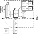
- FIG 1 shows an Unmanned Aerial Vehicle (UAV) Traffic Management (UTM) system 100 for managing UAVs 102 using enhanced flight plans, according to one embodiment.
- the UTM system 100 may be used for managing the flights of one or more UAVs 102 that are controlled/operated/piloted by corresponding UAV operators 104.
- the UAVs 102 may be interchangeably referred to as Unmanned Aircraft Systems (UASs) or drones throughout this description.
- UASs Unmanned Aircraft Systems
- the UAVs 102 may be miniature or small UAVs (sUAVs), which are unmanned aircraft that are small enough to be considered portable by an average man and typically operate/cruise at altitudes lower than larger aircraft.
- a small UAS may be any unmanned aircraft that is fifty-five pounds or lighter and/or is designed to operate below 400 feet.
- the embodiments described herein may be applied to small UAVs, the systems and methods are not restricted to aircraft of these sizes or that are designed to operate at particular altitudes. Instead, the methods and systems described herein may be similarly applied to aircraft of any size or design and with or without an onboard pilot/operator.
- the methods and systems described herein may be used for UAVs 102 larger than fifty-five pounds and/or UAVs 102 that are designed to fly above 400 feet.
- the UAVs 102 are aircraft without an onboard human controller. Instead, the UAVs 102 may be operated/piloted using various degrees of autonomy. For example, a UAV 102 may be operated by a human (e.g., the UAV operator 104) located on the ground or otherwise removed and independent of the location of the UAV 102. For instance, a UAV operator 104 may be located on the ground and acts to directly control each movement of a UAV 102 or a group of UAVs 102 through a radio control interface (e.g., a command and control (C2) interface).
- a radio control interface e.g., a command and control (C2) interface
- the UAV operator 104 may transmit commands via the radio interface to cause the UAV 102 to adjust/move particular flight instruments (e.g., flaps, blades, motors, rotors, etc.) for the purpose of following a flight plan or another set of objectives.
- the UAV operator 104 may provide a flight plan to the UAV 102.
- the UAV 102 may adjust/move particular flight instruments to autonomously fulfill objectives of the flight plan.
- a human operator e.g., the UAV operator 104 may monitor the progress of the flight plan and intervene as needed or as directed.
- the UAV 102 may operate with various levels of autonomy (e.g., fully dependent on a UAV operator 104, partially dependent on a UAV operator 104, or fully independent of a UAV operator 104).
- the UAV operator 104 may be viewed as a remote human controller, a remote digital controller, an onboard digital controller, or a combination of the preceding.
- a flight plan may include a flight path (e.g., a starting point, an ending point, and/or a set of waypoints, where each are defined by longitudinal and latitudinal coordinates), a set of velocities, a set of altitudes, a set of headings/directions, a mission type, a set of events (e.g., capture video at prescribed times or locations, hover over an area for a specified interval, etc.), a time/expiration/duration, and a set of restricted or permitted zones/areas.
- a flight path e.g., a starting point, an ending point, and/or a set of waypoints, where each are defined by longitudinal and latitudinal coordinates
- a set of velocities e.g., a set of altitudes, a set of headings/directions
- a mission type e.g., a set of events (e.g., capture video at prescribed times or locations, hover over an
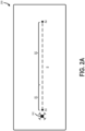
- the flight plan 200 shown in Figure 2A indicates that the UAV 102 is to take off from location A1 (corresponding to a first set of longitude and latitude coordinates) and travel to location A2 (corresponding to a second set of longitude and latitude coordinates) using the path B.
- the path B may be separated into the segments B1 and B2.
- the UAV 102 is restricted to an altitude between 300 feet and 400 feet and a velocity of 100 miles/hour during segment B1 and an altitude between 350 feet and 400 feet and a velocity of 90 miles/hour during segment B2.
- the above altitude and velocity limitations are merely exemplary and in other embodiments higher altitude and velocity limitations may be assigned/issued for a UAV 102 (e.g., altitude limitations above 400 feet and velocity limitations above 100 miles/hour).
- a flight plan 202 may indicate that the UAV 102 is to take off from location A1, travel to location A2, and avoid a set of restricted zones 204A and 204B.
- the UAV 102 is directed to reach the target location A2 without entering the set of restricted zones 204A and 204B.
- the restricted zones may be relative to geographical location (defined by a set of coordinates), an altitude, and/or a velocity.
- the UAV 102 may be permitted to enter restricted zone 204A but only at a prescribed altitude and/or only at a prescribed velocity.
- a flight plan 206 may provide clearance for the UAV 102 to fly in a designated clearance zone 208.
- the clearance zone 208 may be a confined area associated with an altitude range (e.g., between 400-500 feet) and/or an expiration/duration (e.g., an expiration of 11:40PM).
- the UAV 102 may fly anywhere in the designated clearance zone 208 until the clearance has expired.
- the flight plan 210 may include a main flight path 212 and a set of predefined points 138A and 138B.
- the UAV 102 may follow the main flight path 212 and upon detection/occurrence of a condition associated with a predefined point 138A and 138B, the UAV 102 may move off or otherwise deviate from the main flight path 212 and to the corresponding location of the predefined point 138A or 138B.
- the predefined point 138A may be associated with a low charge condition.
- the low charge condition may be related to a battery charge of a battery in the UAV 102 falling below a prescribed level (e.g., battery level is less than 20%).
- the predefined point 138A may also include a charging station location.
- the UAV 102 may autonomously adjust course away from the main flight path 212 to move to the charging station location of the predefined point 138A.
- the UAV 102 may return to the main flight path 212.
- flight plans may be encoded/presented using any format.
- a flight plan may be represented and passed to the UAV 102 using an extensible markup language (XML) based format or another encoding or representation that is decodable and parseable by a machine.
- XML extensible markup language
- FIG. 3 shows a block diagram of a UAV 102 according to one example embodiment.
- Each element of the UAV 102 will be described by way of example below and it is understood that each UAV 102 may include more or less components than those shown and described herein.
- a UAV 102 may include a set of motors 302 controlled by one or more motor controllers 304, which control the speed of rotation of the motors 302 (e.g., rounds per minute).
- the term engine may be used synonymously with the term motor and shall designate a machine that converts one form of energy into mechanical energy.
- the motors 302 may be electrical motors that convert electricity stored in the battery 306 into mechanical energy.
- the UAV 102 may include any number of motors 302 that are placed in any configuration relative to a body and/or an expected heading of the UAV 102.
- the motors 302 may be configured such that the UAV 102 is a multirotor helicopter (e.g., a quadcopter).
- the motors 302 may be configured such that the UAV 102 is a fixed wing aircraft (e.g., a single engine or dual engine airplane). In these embodiments, the motors 302, in conjunction with other elements of the UAV 102 serve to keep the UAV 102 in flight and/or propel the UAV 102 in a desired direction. In some embodiments, the UAV 102 may not include motors 302 for propelling the UAV 102 forward. In this embodiment, the UAV 102 may be a glider or lighter than air craft (e.g., a weather balloon).
- the motors 302 are controlled by one or more motor controllers 304, which govern the speed of rotation of each motor 302.
- the motor controllers 304 may work in conjunction with actuator controllers 308 and actuators 310 that control the pitch/angle/rotation of propellers, flaps, slats, slots, rotors, rotor blades/wings, and other flight control systems 314.
- the motor controllers 304 and actuator controllers 308 may be managed/controlled by one or more processors 312A that are communicatively coupled to a memory 312B and one or more interfaces 312C.
- the memory 312B may store instructions that when executed by the processors 312A cause the UAV 102, via adjustments to settings/parameters of the motor controllers 304 and actuator controllers 308, to move in a particular direction (vertical or horizontal) or maintain a particular flight pattern (e.g., hover at a particular altitude).
- the UAV 102 may communicate with one or more other devices using the one or more interfaces 312C.
- one of the interfaces 312C in a UAV 102 may comply with a 3rd Generation Partnership Project (3GPP) protocol.
- 3GPP 3rd Generation Partnership Project
- the interface 312C may adhere to one or more of Global System for Mobile communications (GSM) (including General Packet Radio Service (GPRS) and Enhanced Data Rates for GSM Evolution (EDGE)), UMTS (including High Speed Packet Access (HSPA)), and Long-Term Evolution (LTE).
- GSM Global System for Mobile communications
- GPRS General Packet Radio Service
- EDGE Enhanced Data Rates for GSM Evolution
- UMTS including High Speed Packet Access (HSPA)
- LTE Long-Term Evolution
- one or more interfaces 312C in the UAV 102 may allow a UAV operator 104 and/or other parts of the UTM system 100 to control or provide plans/instructions to the UAV 102
- one of the interfaces 312C provides access to location information describing the geographical location, velocity, altitude, and heading of the UAV 102.
- the interfaces 312C may provide access to the Global Positioning System (GPS) or other satellite based location services.
- GPS Global Positioning System
- the interfaces 312C may provide access to network based location services (e.g., 3GPP Location Services (LCS)).
- LCS 3GPP Location Services
- a UAV operator 104 may maintain communications with a corresponding UAV 102 via connection 134.
- the connection 134 may be established through one or more interfaces 312C and may form a wireless command and control (C2) connection that allows the UAV operator 104 to control the UAV 102 through direct commands and/or through issuance of a flight plan.
- the connection 134 may additionally allow the UAV operator 104 to receive other forms of data from the UAV 102.
- the data may include images, video streams, telemetry data, and system status (e.g., battery level/status).
- connection 134 may be a point-to-point connection (e.g., mesh) while in other embodiments the connection 134 between the UAV operator 104 and the UAV 102 may be part of a distributed network (e.g., a cellular network).
- a distributed network e.g., a cellular network
- the UAV operator 104 may maintain communication with elements of the UTM system 100 via other corresponding connections.
- the UAV operator 104 may maintain connection 136 with a UAV Service Supplier (USS) 120.
- the connection 136 may be a point-to-point connection while in other embodiments the connection 136 may be part of a distributed network.
- the connection 136 allows the UAV operator 104 to transmit data to or receive data from the USS 120 regarding a current, past, or future flight of the UAV 102.
- the UAV operator 104 may transmit a proposed flight plan to the USS 120 and receive an actual flight plan and/or enhanced flight plan from the USS 120 via the connection 136.
- the UTM system 100 may include a plurality of USSs 120.
- the set of USSs 120 may alternatively be referred to as a USS network.
- Each USS 120 offers support for safe airspace operations based on information received from a set of stakeholders and other information sources.
- the USSs 120 may share information about their supported operations to promote safety and to ensure that each USS 120 has a consistent view of all UAV 102 operations and thus enable the UAVs 102 to stay clear of each other.
- the USSs 120 may receive information from a variety of stakeholders and information sources such that the USSs 120 may determine whether a proposed flight plan or an actual flight plan is authorized to proceed.
- the Federal Aviation Association may provide directives and constraints to the USSs 120 via the Flight Information Management System (FIMS) 122.
- the FIMS 122 provides administration officials a way to issue constraints and directives to the UAV operators 104 and/or the UAVs 102 via a USS 120.
- constraints and directives may be based on information received from the National Airspace System (NAS) Air Traffic Management (ATM) system 124 and/or other NAS data sources 126.
- NAS National Airspace System
- ATM Air Traffic Management
- the ATM system 124 could be used to mark certain restricted areas (e.g., airports and military bases) for the UAVs 102 or restrict flights over forest fire areas or other spaces which are normally permitted for the UAVs 102 to operate.
- the FIMS 122 may provide impact data, which may describe effects caused by the UAVs 102 to a common airspace.
- the USSs 120 may receive constraints from public safety sources 130. This information may limit UAV 102 flights over areas when such flights may negatively affect public safety. For example, UAV 102 missions may be limited over areas that are currently hosting events with large crowds of people.
- the public safety sources 130 may provide data that is presented/transmitted to UAV operators 104 via the USS 120 for the planning of a flight plan/mission.
- the USSs 120 may also make UAV 102 flight/operations information available to the public 132.
- the USSs 120 may receive data from supplemental data service providers 128.
- supplemental data service providers 128 may provide various pieces of data that are used by the USSs 120 in planning and authorizing a flight plan, including terrain, weather, surveillance, and performance information.
- the supplemental data service providers 128 may communicate amongst each other to insure consistency and accuracy of information.
- the supplemental data service providers 128 may provide data that is presented/transmitted to UAV operators 104 via the USS 120 for the planning of a flight plan/mission.
- a supplemental data service provider 128 may provide one or more predefined points 138 to the USS 120 for generation of an enhanced flight path.
- the USS 120 may use data/information received from one or more supplemental data service providers 128 to generate an actual flight plan from a proposed flight plan received from a UAV operator 104.
- the USS 120 may receive approval for the actual flight plan based on inputs from various stakeholders in the corresponding airspace (e.g., FIMS 122).
- the USS 120 may thereafter request a supplemental data service provider 128 to add or suggest predefined points 138 to add to the approved actual flight plan such that an enhanced flight plan may be created.
- the predefined points 138 provide alternative points/locations for a UAV 102 to fly to upon the occurrence of one or more associated conditions.
- the predefined points 138 may provide directions/instructions for the UAV 102 to autonomously deal with unexpected or unplanned issues that arise during the flight of the UAV 102.
- these predefined points 138 may include remote charging service station locations for emergency charging, safe landing locations for emergency grounding, and sheltered locations of safe harbor (e.g., rooftops or cell-tower enclosures).
- predefined points 138 may be associated with attributes, such as priorities (e.g., which predefined point 138 to select for an emergency landing when conditions of multiple predefined points 138 are met) and conditions of use (e.g., use a predefined point 138 only in case of a specific malfunction).
- a predefined point 138 is associated with higher-level directives (e.g., an action to be taken by the UAV 102). For example, for emergency landings, a higher-level directive may be to use a predefined point 138 with a nearest location from the actual/current position of the UAV 102 as a landing spot. The higher-level directive further specifies a prioritization and selection criteria per emergency situation.
- the UAV 102 may always use a predefined point 138 with a nearest location as a landing spot (measured from the last reported position of the UAV 102).
- additional actions may be specified in case the main flight path is aborted and a predefined point 138 is selected by the UAV 102.
- the UAV 102 may signal which landing spot the UAV 102 is approaching (e.g., which predefined point 138 the UAV 102 selected) so the UAV 102 can later be recovered proximate to this landing spot.
- the predefined points 138 may be alternatively referred to as predefined locations, alternative points, alternative locations, conditional points, or conditional locations.
- the USS 120 may transmit an actual flight plan to the supplemental data service provider 128 and the supplemental data service provider 128 may add predefined points 138 to the actual flight plan to generate an enhanced flight plan.
- the supplemental data service provider 128 may thereafter transmit the enhanced flight plan to the USS 120. This enhanced flight plan may thereafter be forwarded to the UAV operator 104.
- the UAV operator 104 may begin controlling the UAV 102 to effectuate the enhanced flight plan or the UAV operator 104 may transmit the enhanced flight plan or some set of instructions describing the objectives of the authorized flight plan, including the predefined points 138, to the UAV 102. For example, the UAV operator 104 may at least transmit the predefined points 138 of an enhanced flight plan to the UAV 102.
- the processor 312A together with instructions stored in the memory 312B may control the motor controllers 304 and/or actuators 310 to achieve the objectives of the enhanced flight plan.
- the UAV 102 may follow a main flight path of the enhanced flight plan until the detection of a condition of a predefined point 138.
- the UAV 102 may deviate from the main flight path and move to a selected location of the predefined point 138.
- the UTM system 100 may update the locations 703 during the flight of a UAV 102. This update may be based on the actual position of the UAV 102 on a flight path (e.g., only update the predefined points 138 ahead of the UAV 102 with respect to the main flight path of the enhanced flight plan).
- the UAVs 102 can leverage information for a safer and a friendlier flight mission with minimum interaction with the UTM system 100, air traffic controllers, and/or a UAV operator 104.
- This framework may yield to many more successfully completed flight missions in a safer and friendlier environment thereby leading to an efficient use of the airspace.
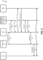
- FIG. 4 an example method 400 will be discussed for generating an enhanced flight plan according to one embodiment.
- the operations in the diagram of Figure 4 will be described with reference to the exemplary implementations of the other figures. However, it should be understood that the operations of the diagram can be performed by implementations other than those discussed with reference to the other figures, and the implementations discussed with reference to these other figures can perform operations different than those discussed with reference to the diagram. Although described and shown in Figure 4 in a particular order, the operations of the method 400 are not restricted to this order. For example, one or more of the operations of the method 400 may be performed in a different order or in partially or fully overlapping time periods. Accordingly, the description and depiction of the method 400 is for illustrative purposes and is not intended to restrict to a particular implementation.
- the method 400 may commence at operation 402 with a UAV operator 104 creating and transmitting a proposed flight plan to a USS 120 of the UTM system 100.
- a UAV operator 104 requests for airspace clearance from the UTM system 100 for a scheduled period of operation. This request for airspace clearance may be expressed in a proposed flight plan.
- Figure 5A shows a proposed flight plan 500 according to one example embodiment. As shown, the proposed flight plan 500 includes a flight path 501, including a start point, an ending point (i.e., a target), and one or more intermediate points through an airspace 503.
- the proposed flight plan 500 may include other elements.
- the proposed flight plan 500 may include in addition to the flight path 501 or in place of the flight path 501, a geofence 505A describing an authorized area of operation (e.g., an area where the UAV 102 is permitted to fly), and/or a geofence 505B describing an unauthorized area of flight (e.g., an area outside of which the UAV 102 is not permitted to fly).
- the proposed flight plan 500 may include one or more of a set of velocities, a set of altitudes, a set of headings/directions, a mission type (e.g., capture video), a set of events (e.g., capture video at prescribed times or locations, hover over an area for a specified interval, etc.), a time/expiration/duration, the type of UAV 102 being used (e.g., flight capabilities of the UAV 102, energy requirements of the UAV 102, and consumption and state of a battery 306 of the UAV 102), and a payload of the UAV 102.
- the proposed flight plan 500 of Figure 5A will be used hereinafter for purposes of explanation; however, it is understood that different proposed flight plans may be used with the method 400.
- the UAV operator 104 may transmit or otherwise make the proposed flight plan 500 available to the UTM system 100.
- the proposed flight plan 500 may be transmitted to the USS 120 such that, as described below, the USS 120 may request an actual flight plan from the supplemental data service providers 128 and/or verify that the proposed flight plan 500 and/or the actual flight plan complies with a set of directives and constraints issued by a regulatory authority/agency or another stakeholder (e.g., FIMS 122, public safety sources 130, etc.) in the airspace 503.
- a regulatory authority/agency or another stakeholder e.g., FIMS 122, public safety sources 130, etc.
- the USS 120 may issue a request for an actual flight plan to a set of supplemental data service providers 128.
- the request may include the proposed flight plan 500.
- the supplemental data service providers 128 may provide terrain, weather, surveillance, and performance information for adjusting the proposed flight plan 500 to create the actual flight plan, which is transmitted to the USS 120 at operation 406.
- the USS 120 may generate the actual flight plan based on inputs from the supplemental data service providers 128.
- the UAV operator 104 may generate the actual flight plan with assistance from the USS 120 based on inputs from the supplemental data service providers 128.
- Figure 6 shows an actual flight plan 600 according to one example embodiment.
- the actual flight plan 600 may include a flight path 601 that has been adjusted from the flight path 501 of the proposed flight plan 500.
- the adjustment may have been caused by terrain, weather, surveillance, and/or performance information.
- the adjustment to the flight path 501 to create the flight path 601 may have been made to avoid a weather condition.
- the actual flight plan 600 may be transmitted to the FIMS 122 for verification.
- the verification may include determining that the actual flight plan 600 complies with a set of directives and constraints issued by a regulatory authority that manages the airspace 503 covered by the actual flight plan 600 (e.g., the FAA).
- a regulatory authority that manages the airspace 503 covered by the actual flight plan 600
- the systems and methods described herein may be similarly applied using any regulatory authority/agency overseeing any jurisdiction/territory/airspace.
- the FIMS 122 may provide an approval to the USS 120 at operation 410.
- the USS 120 may verify that the actual flight plan 600 complies with all applicable directives and constraints based on inputs from the FIMS 122.
- the actual flight plan 600 may be modified to comply with the directives and constraints.
- the USS 120 may request an enhanced flight plan from a supplemental data service provider 128, and the supplemental data service provider 128 may return the enhanced flight plan to the USS 120 at operation 414.
- the enhanced flight plan may include the details of the actual flight plan 600 in addition to a set of predefined points 138.
- the enhanced flight plan described hereinafter will include details of the actual flight plan 600 in addition to a set of predefined points 138.
- the predefined points 138 may describe some combination of remote charging service station locations for emergency charging, safe landing locations for emergency grounding, and sheltered locations of safe harbor (e.g., rooftops or cell-tower enclosures), or other points outside the flight path 601.
- each of the predefined points 138 may comply with all directives, constraints, and other rules and regulations issued by a regulatory authority or other stakeholders of the common airspace 503.
- a predefined point 138 may be defined by a set of conditions 701 and a set of locations 703. Upon detection of the set of conditions 701 for a predefined point 138, the UAV 102 acts autonomously to move to the set of locations 703 associated with the predefined point 138 for which the condition 701 was detected.
- Figure 8 shows an enhanced flight plan 800 that includes a flight path 601 from the actual flight plan 600 (sometimes referred to as a main flight path 601 or an original flight path 601) and predefined points 138A-138C.
- the predefined point 138A may include a low battery condition 701 corresponding to the battery 306 of the UAV 102 being below a predefined level (e.g., the battery 306 of the UAV 102 is below 20%) and an associated location 703 may be the location of a charging station.
- the UAV 102 may deviate from the original/main flight path 601 and head to the associated location 703 of the predefined point 138A (i.e., the location of the charging station).
- the original/main flight path 601 may be a flight path provided by the actual flight plan 600, which is also included in the enhanced flight plan 800, while the predefined points 138 of the enhanced flight plan 800 define alternative paths or deviations for the UAV 102 to take when associated conditions 701 are detected.
- the predefined points 138 may be stored/downloaded to a UAV 102 for use upon occurrence of a condition 701 as will be described below.
- locations 703 of predefined points 138 may be defined/represented by a set of geographical coordinates (e.g., longitude, latitude, and/or altitude).
- the locations 703 may be an area in the airspace 503.
- a location 703 of a predefined point 138 may be defined/represented by a set of coordinates (e.g., longitude, latitude, and/or altitude) and a distance.
- the area of the location 703 is a sphere centered at the coordinates with a radius of the provided distance measure.
- the area of a location 703 may be other two or three-dimensional shapes that are defined/represented by multiple sets of coordinates and/or distance measures.
- a set of four coordinate groups may represent a rectangular open field that may be used by the UAV 102 for landing.
- a predefined point 138 may include authentication and security keys 705 for establishing communications with or access to a service system at a location 703.
- a location 703 of a predefined point 138 may provide a beacon for guiding the UAV 102 to a landing or charging station.
- the predefined point 138 that is part of an enhanced flight plan 800 may include authentication and security keys 705 for gaining access to the beacon.
- the predefined point 138 may include authentication and security keys 705 for accessing a charging station at a location 703 specified in the predefined point 138.
- a predefined point 138 may be associated with priority information 707 (e.g., which emergency landing location 703 to select when a predefined point 138 includes multiple locations 703) and condition of use information 709 (e.g., a condition 701 indicates the occurrence of a malfunction and the condition of use information 709 indicates that a location 703 may only be used in case of a specific malfunction).
- priority information 707 e.g., which emergency landing location 703 to select when a predefined point 138 includes multiple locations 703
- condition of use information 709 e.g., a condition 701 indicates the occurrence of a malfunction and the condition of use information 709 indicates that a location 703 may only be used in case of a specific malfunction.
- each type of predefined point 138 is associated with a higher-level directive 711 (e.g., an action to be taken by the UAV 102).
- a higher-level directive 711 may be to use the nearest location 703 of a set of locations 703, from the actual/current position of the UAV 102, as a landing spot.
- the higher-level directive 711 further specifies a prioritization and selection criteria per emergency situation. For instance, in case of the loss of communications with a UAV operator 104, a higher-level directive 711 may be to always use the nearest location 703 of a set of locations 703, from the last reported position of the UAV 102, as a landing spot for the UAV 102.
- a higher-level directive 711 may include additional actions to be taken by the UAV 102.
- an additional action 713 includes the UAV 102 signaling to the UTM system 100 or otherwise broadcasting which landing spot the UAV 102 is approaching so the UAV 102 can later be recovered.
- the predefined points 138 may be provided by a supplemental data service provider 128.
- the supplemental data service provider 128 used at operations 412 and 414 to add predefined points 138 to the actual flight plan 600 may be different/distinct from the supplemental data service provider 128 used at operations 404 and 406.
- the supplemental data service provider 128 may provide a set of predefined points 138 to the USS 120, and the USS 120 (with or without assistance from the UAV operator 104) may generate the enhanced flight plan 800 using the set of predefined points 138. Accordingly, the USS 120 and/or the UAV operator 104 may be tasked with selecting and incorporating predefined points 138 into the enhanced flight plan 800.
- the enhanced flight plan 800 may be transmitted to the UAV operator 104.
- the UAV operator 104 may thereafter start to carry out the enhanced flight plan 800 at operation 418.
- part or all of the enhanced flight plan 800 may be transmitted and stored on the UAV 102.
- the predefined points 138 of the enhanced flight plan 800 may be stored on the UAV 102 (e.g., in memory 312B).
- the predefined points 138 may be stored on the UAV 102 in prioritized order and consulted by the UAV 102 when an emergency or malfunction arises as a contingency for safe action (e.g., landing pad or charging station, which is either closest or is preferred).
- a condition 701 may be detected that causes the UAV 102 to autonomously adjust navigation settings and target a location 703 indicated by one of the predefined points 138.
- a predefined point 138 may include a motor 302 malfunction condition 701 and an emergency landing site location 703.
- the UAV 102 may determine that the motor 302 malfunction condition 701 has been met and in response may autonomously begin movement to the emergency landing location 703 associated with the motor 302 malfunction condition 701.
- a predefined point 138 may include a remote abort condition 701 and a plurality of landing site locations 703.
- the UAV 102 may prioritize the plurality of landing site locations 703 based on distance from the current location of the UAV 102 and select an emergency landing location 703.
- a predefined point 138 may be used in cases where redundant command and control (C2) links and a high/wide-bandwidth link (e.g., cellular/LTE connection) have failed, but a low/narrow-bandwidth link remains.
- C2 redundant command and control
- a high/wide-bandwidth link e.g., cellular/LTE connection
- the UTM system 100 may issue an abort command and immediately transmit a land trigger to the UAV 102.
- the UAV 102 may retrieve a set of stored safe landing locations 703.
- the UAV 102 may inform the USS 120 of a safe landing and the location 703 of the landing via the low/narrow-bandwidth link.
- a predefined point 138 may be used to navigate to regain a C2 link. For example, upon detecting a triggering condition 701 of a loss of a C2 link, the UAV 102 may identify a set of network tower locations 703 associated with the condition 701. The UAV 102 may thereafter autonomously navigate to a closest or preferred network tower at a location 703 specified by a predefined point 138 in an attempt to regain the C2 link.
- the predefined point 138 and associated condition 701 described above may be further extended to include a further failure to establish the C2 link condition 701. Upon detecting a further failure condition 701 (e.g., after passage of a defined period of time), the UAV 102 may navigate to an emergency landing location 703 associated with the predefined point 138.
- the predefined points 138 may include locations 703 (e.g., a point defined by a set of coordinates or an area defined by coordinates and/or distance measures) of high network availability (e.g., a signal strength or signal-to-noise ratio above a defined level or above a current level).
- locations 703 of high quality network signal may be proximate to a network tower or they may be at some distance from the tower.
- network infrastructure e.g., network/communication towers
- the landing location 703 may provide various services, including battery charging, reestablishment of a C2 link, and shelter from a meteorological/weather condition 701 until the condition 701 has passed.
- a predefined point 138 may be associated with different weather conditions 701.
- different predefined points 138 may be associated with different weather conditions 701 and/or different locations 703 where weather conditions 701 often change (e.g., micro weather conditions 701).
- the weather conditions 701 associated with the predefined point 138 may be taken into account before making a decision (e.g., selecting a landing location 703).
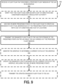
- FIG. 9 a method 900 will be described for managing a flight of a UAV 102 according to one example embodiment.
- the operations in the diagram of Figure 9 will be described with reference to the exemplary implementations of the other figures. However, it should be understood that the operations of the diagram can be performed by implementations other than those discussed with reference to the other figures, and the implementations discussed with reference to these other figures can perform operations different than those discussed with reference to the diagram.
- the operations of the method 900 are not restricted to this order.
- one or more of the operations of the method 900 may be performed in a different order or in partially or fully overlapping time periods. Accordingly, the description and depiction of the method 900 is for illustrative purposes and is not intended to restrict to a particular implementation.
- the method 900 may commence at operation 902 with the UTM system 100 receiving a flight plan that describes a proposed flight mission of the UAV 102 in an airspace.
- the flight plan received at operation 902 may be the proposed flight plan 500 of Figure 5A or Figure 5B .
- the flight plan received at operation 902 may be the actual flight plan 600 of Figure 6 .
- the UTM system 100 may verify that the flight plan received at operation 902 complies with a set of directives and constraints issued by a regulatory authority.
- the USS 120 of the UTM system 100 may work with various organization/stakeholders (e.g., FIMS 122) at operation 904 to verify that the flight plan received at operation 902 complies with a set of directives and constraints.
- the flight plan received at operation 902 may be modified at operation 904 to comply with the set of directives and constraints.
- the UTM system 100 may add one or more predefined points 138 to the flight plan to create an enhanced flight plan 800, wherein each of the predefined points 138 is associated with a set of conditions 701 and a set of locations 703.
- each predefined point 138 in the one or more predefined points 138 complies with the set of directives and constraints used at operation 904.
- a predefined point 138 in the one or more predefined points 138 is associated with a higher-level directive 711 describing an action to be taken by the UAV 102 upon detecting an occurrence of a condition 701 in the set of conditions 701 associated with the predefined point 138.
- a higher-level directive 711 of a predefined point 138 includes prioritization and selection criteria for selecting a location 703 from the set of locations 703 associated with the predefined point 138.
- a higher-level directive 711 of a predefined point 138 includes transmitting an indication of a selected location 703 from the set of locations 703 associated with the predefined point 138 to a device/entity separate from the UAV 102 (e.g., the UTM system 100 and/or another UAV 102).
- the set of locations 703 associated with a predefined point 138 in the one or more predefined points 138 is a plurality of locations 703 that are each associated with a single condition 701.
- each location 703 in the plurality of locations 703 may be associated with priority information 707 such that the UAV 102 considers adjusting a flight of the UAV 102 using one location 703 in the plurality of locations 703 based on the priority information 707 associated with each location 703 in the plurality of locations 703 upon detecting the occurrence of the single condition 701.
- a predefined point 138 in the one or more predefined points 138 is associated with a loss of a UAV operator 104 connection 134 condition 701 and a set of locations 703 corresponding to locations of high network availability such that, upon detecting a loss of a connection 134 with a UAV operator 104, the UAV 102 is to autonomously decide to navigate to a location 703 in the set of locations 703 corresponding to locations of high network availability to regain the connection 134 with the UAV operator 104.
- the locations 703 of high network availability are locations of communication towers (e.g., cell towers).
- the predefined point 138 in the one or more predefined points 138 is further associated with a failure to regain a UAV operator 104 connection 134 condition 701 and a set of locations 703 corresponding to safe landing zones such that, after detecting the loss of a UAV operator 104 connection 134 condition 701, navigating to a high network availability location 703, failing to regain the connection 134 with the UAV operator 104, and upon detecting a failure to regain connection 134 with the UAV operator 104, the UAV 102 is to autonomously decide to land at a location 703 in the set of locations 703 corresponding to the safe landing zones.
- a predefined point 138 in the one or more predefined points 138 is associated with a low battery 306 condition 701 and a set of locations 703 corresponding to safe landing zones for charging the UAV 102.
- the UAV 102 Upon detecting a battery 306 level of the UAV 102 below a defined level, the UAV 102 is to autonomously decide to land at a location 703 in the set of locations 703 corresponding to the safe landing zones.
- a predefined point 138 in the one or more predefined points 138 is associated with a severe weather condition 701 and a set of locations 703 corresponding to safe landing zones.
- the UAV 102 Upon detecting a severe weather condition 701, the UAV 102 is to autonomously decide to land at a location 703 in the set of locations 703 corresponding to the safe landing zones.
- the UTM system 100 may transmit the enhanced flight plan 800 to the UAV 102 for storage of the predefined points 138 on the UAV 102 while the UAV 102 carries out the proposed flight mission.
- the enhanced flight plan 800 may be first transmitted or otherwise made available to the UAV operator 104 such that the UAV operator 104 may transmit the enhanced flight plan 800 to the UAV 102.
- the UTM system 100 may monitor the airspace to determine a current status of the airspace 503.
- This monitoring of the airspace 503 may include monitoring the status of other UAVs 102, other aircraft (e.g., planes, helicopters, or other airborne entities), weather conditions, locations 703 included in predefined points 138, etc.
- the UTM system 100 may update the enhanced flight plan 800 based on the current status of the airspace 503, including the one or more predefined points 138. For example, in response to determining that a location 703 included in a predefined point 138 is occupied, the predefined point 138 of the enhanced flight plan 800 may be updated to remove or update the occupied location.
- the UTM system 100 may transmit the updated enhanced flight plan 800 to the UAV 102.
- the UTM system 100 may transmit to the UAV 102 information indicating only what has changed (i.e., based on the current status of the airspace monitored at operation 910) for the enhanced flight plan 800.
- an existing predefined point 138 of the enhanced flight plan 800 transmitted at operation 908 may no longer be viable (e.g., due to malfunction), and a new predefined point 138 may be added (e.g., a previously occupied charging station is now available).
- the UTM system 100 may transmit a replacement list of predefined points 138, or may instead transmit information about the new predefined point 138 and an indication that the existing predefined point 138 is no longer operational.
- FIG. 10 a method 1000 will be described for controlling a UAV 102 according to one example embodiment.
- the operations in the diagram of Figure 10 will be described with reference to the exemplary implementations of the other figures. However, it should be understood that the operations of the diagram can be performed by implementations other than those discussed with reference to the other figures, and the implementations discussed with reference to these other figures can perform operations different than those discussed with reference to the diagram. Although described and shown in Figure 10 in a particular order, the operations of the method 1000 are not restricted to this order. For example, one or more of the operations of the method 1000 may be performed in a different order or in partially or fully overlapping time periods. Accordingly, the description and depiction of the method 1000 is for illustrative purposes and is not intended to restrict to a particular implementation.
- the method 1000 may commence at operation 1002 with the UAV 102 receiving an enhanced flight plan, wherein the enhanced flight plan includes one or more predefined points 138 and each of the predefined points 138 is associated with a set of conditions 701 and a set of locations 703.
- the UAV 102 may receive the enhanced flight plan 800 at operation 1002.
- the UAV 102 may store the one or more predefined points 138 of the enhanced flight plan 800.
- the UAV 102 may store the entire enhanced flight plan 800, including the predefined points 138, while in other embodiments, the UAV 102 may just store the predefined points 138 at operation 1004.
- the predefined points 138 indicate deviations, relative to a main flight path 601, for the UAV 102 to follow upon occurrence of an unexpected event that matches a condition 701 of a predefined point 138.
- the UAV 102 may be flown according to the enhanced flight plan 800.
- the UAV 102 may be flown according to the main flight path 601 at operation 1006 (either autonomously or based on inputs form the UAV operator 104). Accordingly, the UAV 102 is flown according to a known and pre-planned route/path at operation 1006.
- the UAV 102 may detect a condition 701 associated with a predefined point 138 in the one or more predefined points 138 stored in the UAV 102.
- the UAV 102 may adjust, autonomously and in response to detecting the condition 701, a flight of the UAV 102 using a set of locations 703 associated with the predefined point 138 and associated with the detected condition 701.
- the predefined point 138 in the one or more predefined points 138 is associated with a plurality of locations 703 that are each associated with a single condition 701, and each location 703 in the plurality of locations 703 is associated with a priority (i.e., priority information 707).
- adjusting the flight of the UAV 102 may include adjusting the flight of the UAV 102 using one location in the plurality of locations based on the priority associated with each location in the plurality of locations upon detecting the occurrence of the single condition.
- the predefined point 138 in the one or more predefined points 138 is associated with a higher-level directive 711 describing an action to be taken by the UAV 102 upon detecting an occurrence of the condition 701 associated with the predefined point 138.
- the higher-level directive 711 of the predefined point 138 includes prioritization and selection criteria for selecting a location 703 from the set of locations 703 associated with the predefined point 138.
- the higher-level directive 711 of the predefined point 138 includes transmitting an indication of a selected location 703 from the set of locations 703 associated with the predefined point 138 to a device/entity separate from the UAV 102 (e.g., the UTM system 100).
- the UAV 102 may receive an update to the enhanced flight plan 800, including one or more of a new predefined point 138 and an update to an existing predefined point 138.
- the UAV 102 may receive information indicating only what has changed for the enhanced flight plan 800.
- the UAV 102 may receive a replacement list of predefined points 138 or may instead receive information about the one or more new predefined points 138 and an indication that the existing predefined point 138 changed (e.g., is no longer operational).
- the UAV 102 may update the stored predefined points 138 with the received updated enhanced flight plan 800, a received replacement list of predefined points 138, or any other information/indication of changed/new predefined points 138.
- the UAVs 102 can leverage information for a safer and a friendlier flight mission with minimum interaction with the UTM system 100, air traffic controllers, and/or a UAV operator 104.
- This framework may yield to many more successfully completed flight missions in a safer and friendlier environment thereby leading to an efficient use of the airspace.
- Each element of the UTM system 100 may be composed of or otherwise implemented by a set of computing/networking devices.
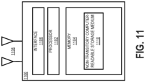
- Figure 11 illustrates a computing/networking device 1100 according to one embodiment.
- the computing/networking device 1100 may include a processor 1102 communicatively coupled to a memory 1104 and an interface 1106.
- the processor 1102 may be a microprocessor, controller, microcontroller, central processing unit, digital signal processor, application specific integrated circuit, field programmable gate array, any other type of electronic circuitry, or any combination of one or more of the preceding.
- the processor 1102 may comprise one or more processor cores.
- some or all of the functionality described herein as being provided by a component of the UTM system 100 may be implemented by one or more processors 1102 of one or more computing/networking devices 1100 executing software instructions, either alone or in conjunction with other computing/networking devices 1100 components, such as the memory 1104.
- the memory 1104 may store code (which is composed of software instructions and which is sometimes referred to as computer program code or a computer program) and/or data using non-transitory machine-readable (e.g., computer-readable) media, such as a non-transitory computer-readable storage medium (e.g., magnetic disks, optical disks, solid state drives, read only memory (ROM), flash memory devices, phase change memory) and machine-readable transmission media (e.g., electrical, optical, radio, acoustical or other form of propagated signals - such as carrier waves, infrared signals).
- the memory 1104 may comprise non-volatile memory (e.g., a non-transitory computer-readable storage medium 1110) containing code to be executed by the processor 1102.
- the code and/or data stored therein can persist even when the computing/networking device 1100 is turned off (when power is removed). In some instances, while the computing/networking device 1100 is turned on, that part of the code that is to be executed by the processor(s) 1102 may be copied from non-volatile memory into volatile memory (e.g., dynamic random-access memory (DRAM), static random-access memory (SRAM)) of the computing/networking device 1100.
- volatile memory e.g., dynamic random-access memory (DRAM), static random-access memory (SRAM)
- the interface 1106 may be used in the wired and/or wireless communication of signaling and/or data to or from computing/networking device 1100.
- interface 1106 may perform any formatting, coding, or translating to allow computing/networking device 1100 to send and receive data whether over a wired and/or a wireless connection.
- the interface 1106 may comprise radio circuitry capable of receiving data from other devices in the network over a wireless connection and/or sending data out to other devices via a wireless connection.
- This radio circuitry may include transmitter(s), receiver(s), and/or transceiver(s) suitable for radiofrequency communication.
- the radio circuitry may convert digital data into a radio signal having the appropriate parameters (e.g., frequency, timing, channel, bandwidth, etc.).
- interface 1106 may comprise network interface controller(s) (NICs), also known as a network interface card, network adapter, local area network (LAN) adapter or physical network interface.
- NICs network interface controller(s)
- the NIC(s) may facilitate in connecting the computing/networking device 1100 to other devices allowing them to communicate via wire through plugging in a cable to a physical port connected to a NIC.
- the processor 1102 may represent part of the interface 1106, and some or all of the functionality described as being provided by the interface 1106 may be provided in part or in whole by the processor 1102.
Description
- Embodiments of the invention relate to the field of managing Unmanned Aerial Vehicles (UAVs); and more specifically, to managing UAVs in an UAV Traffic Management (UTM) framework by adding predefined points to a flight plan of the UAV.
- In this specifications the following non-SI units are used, which may be converted to the respective SI or metric unit according to the following conversion table:
- Foot: 1 ft = 0.3048 m
- Pounds: 1 lb = 453,592 g
- Miles/hour: 1 mph = 0,44704 m.s-1
- There is increasing interest in using Unmanned Aerial Vehicle's (UAVs) for a wide variety of applications throughout society and, in particular, small UAVs (sUAVs). Examples include delivery services, aerial photography and film making, remote sensing tasks for agriculture, city planning, civil engineering, and support for public safety and rescue services. These applications all involve the use of UAVs operating at low altitudes and often above urban areas. In some situations, the UAVs are manually flown by their operator while in other situations the UAVs may be flown using some level of autonomy where a human operator monitors multiple aircraft and intervenes only when trouble arises.
- With more aircraft in operation, possibly being flown autonomously or controlled from a remote location, monitoring, controlling, and planning air traffic becomes an important and complex issue. This level of traffic management requires an air traffic control system that can (1) handle both manually flown (remote or onsite control) and autonomous UAVs, (2) integrate with existing air traffic control systems to ensure safe operations with other systems flying in the same airspace, (3) distribute relevant information to all parties/stakeholders, including making operators aware of the environment around the aircraft they are flying (e.g., who is flying where, their planned route, temporary obstacles, weather situations, etc.), and (4) allow regulatory authorities the ability to monitor the airspace, reserve or restrict airspace access, or close the airspace entirely.
- Overall system efficiency will suffer if a human air traffic controller must be involved in handling each request from UAV operators. Many tasks can be performed and verified automatically by air traffic control computers, including registering flight plans, computing flight plans, approving altitude changes, and general flight monitoring. With greater computing flight plans, approving altitude changes, and general flight monitoring. With greater automation, air traffic may be streamlined and human controllers may be assigned to handle more UAV flights.
- However, current UAVs provide little automation when unexpected issues arise. In particular, current UAVs are programmed with a single default emergency action of either grounding or aborting the current mission in progress and returning home. The emergency action is triggered primarily by the drop of battery level or the loss of connectivity over a command and control (C2) connection with the UAV operator. However, there may be numerous other triggers for aborting flight missions (e.g., meteorological disturbances). Thus, a single emergency action is insufficient to cover all possible flight issues. Further, safe grounding of a UAV can be called into question when the mission is being flown over a body of water or over hostile or hazardous terrain. Moreover, UAV operators are also mandated to be mindful of "no fly zones" (e.g., restricted airspaces, such as airports or other areas of national security interest). These restrictions are fed into flight path calculations, which are typically performed manually or by UAV Traffic Management (UTM) systems. However, these restrictions are not considered when emergency actions are taken by UAVs. Accordingly, as described above, current UAV flight management systems fail to properly and efficiently address the large number of unexpected issues that may arise during the course of a UAV flight. Consequently, these unexpected issues require the intervention from a human flight traffic controller and/or a human UAV operator.
- Methods for controlling an Unmanned Aerial Vehicle according to the state of the art are known, for instance, from documents
US 2017/092137 A1 ,US 9 588 516 B1 US 9 609 188 B1 - A first aspect of the invention relates to a method for controlling an UAV according to appended claim 1. Advantageous features are set out in the appended dependent claims 2-12.
- A second aspect of the invention relates to a non-transitory computer-readable storage medium according to appended claim 13.
- A third aspect of the invention relates to a network device for managing an Unmanned Aerial Vehicle according to appended claim 14.
- The invention may best be understood by referring to the following description and accompanying drawings that are used to illustrate embodiments of the invention. In the drawings:
-
Figure 1 illustrates an Unmanned Aerial Vehicle (UAV) Traffic Management (UTM) system according to one embodiment; -
Figure 2A illustrates an example flight plan with a set of coordinates according to one embodiment; -
Figure 2B illustrates an example flight plan with a set of restricted areas/zones according to one embodiment; -
Figure 2C illustrates an example flight plan with a designated clearance zone according to one embodiment; -
Figure 2D illustrates an example flight plan with predefined points according to one embodiment; -
Figure 3 illustrates a block diagram of a UAV according to one embodiment; -
Figure 4 illustrates a method for generating a flight plan according to one embodiment; -
Figure 5A shows a proposed flight plan, including a flight path, according to one embodiment; -
Figure 5B shows a proposed flight plan, including a flight path and a set of geofences, according to one embodiment; -
Figure 6 shows an actual flight plan according to one embodiment; -
Figure 7 shows a predefined location according to one embodiment; -
Figure 8 shows an enhanced flight plan according to one embodiment; -
Figure 9 illustrates a method for managing a flight of a UAV according to one embodiment; -
Figure 10 illustrates a method for controlling a flight of a UAV according to one embodiment; and -
Figure 11 illustrates a computing/networking device according to one embodiment. - In the following description, numerous specific details are set forth. However, it is understood that embodiments of the invention may be practiced without these specific details. In other instances, well-known circuits, structures and techniques have not been shown in detail in order not to obscure the understanding of this description. Those of ordinary skill in the art, with the included descriptions, will be able to implement appropriate functionality without undue experimentation.
- Bracketed text and blocks with dashed borders (e.g., large dashes, small dashes, dot-dash, and dots) are used herein to illustrate optional operations that add additional features to embodiments of the invention. However, such notation should not be taken to mean that these are the only options or optional operations, and/or that blocks with solid borders are not optional in certain embodiments of the invention.
- References in the specification to "one embodiment," "an embodiment," "an example embodiment," etc., indicate that the embodiment described may include a particular feature, structure, or characteristic, but every embodiment may not necessarily include the particular feature, structure, or characteristic. Moreover, such phrases are not necessarily referring to the same embodiment. Further, when a particular feature, structure, or characteristic is described in connection with an embodiment, it is submitted that it is within the knowledge of one skilled in the art to affect such feature, structure, or characteristic in connection with other embodiments whether or not explicitly described.
- In the following description and claims, the terms "coupled" and "connected," along with their derivatives, may be used. It should be understood that these terms are not intended as synonyms for each other. "Coupled" is used to indicate that two or more elements, which may or may not be in direct physical or electrical contact with each other, co-operate or interact with each other. "Connected" is used to indicate the establishment of communication between two or more elements that are coupled with each other.
- An electronic device stores and transmits (internally and/or with other electronic devices over a network) code (which is composed of software instructions and which is sometimes referred to as computer program code or a computer program) and/or data using machine-readable media (also called computer-readable media), such as machine-readable storage media (e.g., magnetic disks, optical disks, read only memory (ROM), flash memory devices, phase change memory) and machine-readable transmission media (also called a carrier) (e.g., electrical, optical, radio, acoustical or other form of propagated signals - such as carrier waves, infrared signals). Thus, an electronic device (e.g., a computer) includes hardware and software, such as a set of one or more processors coupled to one or more machine-readable storage media to store code for execution on the set of processors and/or to store data. For instance, an electronic device may include non-volatile memory containing the code since the non-volatile memory can persist the code even when the electronic device is turned off, and while the electronic device is turned on that part of the code that is to be executed by the processor(s) of that electronic device is copied from the slower non-volatile memory into volatile memory (e.g., dynamic random access memory (DRAM), static random access memory (SRAM)) of that electronic device. Typical electronic devices also include a set or one or more physical network interface(s) to establish network connections (to transmit and/or receive code and/or data using propagating signals) with other electronic devices. One or more parts of an embodiment of the invention may be implemented using different combinations of software, firmware, and/or hardware.
- A system, according to one embodiment, is presented herein that enhances a flight plan for Unmanned Aerial Vehicles (UAVs) by incorporating/adding predefined points to the flight plan. In one embodiment, a UAV operator may present a proposed flight plan, including a flight path, to a UAV Traffic Management (UTM) system. The UTM system may generate an actual flight plan based on the proposed flight plan and verify that the actual flight plan complies with directives, constraints, or other rules/regulations issued by a regulatory authority and/or other stakeholders/services. In some embodiments, a supplemental data service provider may make a set of predefined points available for modifying the actual flight plan to produce an enhanced flight plan. In these embodiments, the enhanced flight plan includes at least a main flight path (taken from the actual flight plan) and a set of predefined points. In one embodiment, each of the predefined points may include a set of conditions and a set of locations. For example, a predefined point may include a low battery condition (e.g., the battery of the UAV is below ten percent) and a set of charging station locations associated with the low battery condition. In this example embodiment, upon detection of the low battery condition, the UAV may autonomously select one of the charging station locations and deviate from the main flight path to navigate to the selected charging station location. The enhanced flight plan, including at least the predefined points, may be delivered to and stored on the UAV such that upon encountering an unexpected issue during a flight (i.e., an issue matching a condition of a predefined point), the UAV may autonomously and dynamically alter its flight (e.g., deviate from the main flight path) based on a corresponding predefined point. By providing flexible and extensible enhancements to the permission to use an airspace, UAVs can leverage information for a safer and a friendlier flight mission with minimum interaction with the UTM, air traffic controllers, and/or a UAV operator. This framework may yield to many more successfully completed flight missions in a safer and friendlier environment thereby leading to an efficient use of the airspace.
-
Figure 1 shows an Unmanned Aerial Vehicle (UAV) Traffic Management (UTM) system 100 for managingUAVs 102 using enhanced flight plans, according to one embodiment. The UTM system 100 may be used for managing the flights of one ormore UAVs 102 that are controlled/operated/piloted by correspondingUAV operators 104. TheUAVs 102 may be interchangeably referred to as Unmanned Aircraft Systems (UASs) or drones throughout this description. - In some embodiments, the
UAVs 102 may be miniature or small UAVs (sUAVs), which are unmanned aircraft that are small enough to be considered portable by an average man and typically operate/cruise at altitudes lower than larger aircraft. For example, a small UAS may be any unmanned aircraft that is fifty-five pounds or lighter and/or is designed to operate below 400 feet. Although the embodiments described herein may be applied to small UAVs, the systems and methods are not restricted to aircraft of these sizes or that are designed to operate at particular altitudes. Instead, the methods and systems described herein may be similarly applied to aircraft of any size or design and with or without an onboard pilot/operator. For example, in some embodiments, the methods and systems described herein may be used forUAVs 102 larger than fifty-five pounds and/orUAVs 102 that are designed to fly above 400 feet. - The
UAVs 102 are aircraft without an onboard human controller. Instead, theUAVs 102 may be operated/piloted using various degrees of autonomy. For example, aUAV 102 may be operated by a human (e.g., the UAV operator 104) located on the ground or otherwise removed and independent of the location of theUAV 102. For instance, aUAV operator 104 may be located on the ground and acts to directly control each movement of aUAV 102 or a group ofUAVs 102 through a radio control interface (e.g., a command and control (C2) interface). In this embodiment, theUAV operator 104 may transmit commands via the radio interface to cause theUAV 102 to adjust/move particular flight instruments (e.g., flaps, blades, motors, rotors, etc.) for the purpose of following a flight plan or another set of objectives. In other scenarios, theUAV operator 104 may provide a flight plan to theUAV 102. In response to the flight plan, theUAV 102 may adjust/move particular flight instruments to autonomously fulfill objectives of the flight plan. In these embodiments, a human operator (e.g., the UAV operator 104) may monitor the progress of the flight plan and intervene as needed or as directed. Accordingly, theUAV 102 may operate with various levels of autonomy (e.g., fully dependent on aUAV operator 104, partially dependent on aUAV operator 104, or fully independent of a UAV operator 104). In some embodiments, theUAV operator 104 may be viewed as a remote human controller, a remote digital controller, an onboard digital controller, or a combination of the preceding. - In some embodiments, a flight plan may include a flight path (e.g., a starting point, an ending point, and/or a set of waypoints, where each are defined by longitudinal and latitudinal coordinates), a set of velocities, a set of altitudes, a set of headings/directions, a mission type, a set of events (e.g., capture video at prescribed times or locations, hover over an area for a specified interval, etc.), a time/expiration/duration, and a set of restricted or permitted zones/areas. For instance, the
flight plan 200 shown inFigure 2A indicates that theUAV 102 is to take off from location A1 (corresponding to a first set of longitude and latitude coordinates) and travel to location A2 (corresponding to a second set of longitude and latitude coordinates) using the path B. The path B may be separated into the segments B1 and B2. In this scenario, theUAV 102 is restricted to an altitude between 300 feet and 400 feet and a velocity of 100 miles/hour during segment B1 and an altitude between 350 feet and 400 feet and a velocity of 90 miles/hour during segment B2. The above altitude and velocity limitations are merely exemplary and in other embodiments higher altitude and velocity limitations may be assigned/issued for a UAV 102 (e.g., altitude limitations above 400 feet and velocity limitations above 100 miles/hour). - In another example, as shown in
Figure 2B , aflight plan 202 may indicate that theUAV 102 is to take off from location A1, travel to location A2, and avoid a set ofrestricted zones UAV 102 is directed to reach the target location A2 without entering the set ofrestricted zones UAV 102 may be permitted to enter restrictedzone 204A but only at a prescribed altitude and/or only at a prescribed velocity. - In still another example, shown in
Figure 2C , aflight plan 206 may provide clearance for theUAV 102 to fly in a designatedclearance zone 208. Theclearance zone 208 may be a confined area associated with an altitude range (e.g., between 400-500 feet) and/or an expiration/duration (e.g., an expiration of 11:40PM). In this example, theUAV 102 may fly anywhere in the designatedclearance zone 208 until the clearance has expired. - In yet another example, shown in
Figure 2D , theflight plan 210 may include amain flight path 212 and a set ofpredefined points UAV 102 may follow themain flight path 212 and upon detection/occurrence of a condition associated with apredefined point UAV 102 may move off or otherwise deviate from themain flight path 212 and to the corresponding location of thepredefined point predefined point 138A may be associated with a low charge condition. The low charge condition may be related to a battery charge of a battery in theUAV 102 falling below a prescribed level (e.g., battery level is less than 20%). In this example, thepredefined point 138A may also include a charging station location. Upon detecting the low battery condition (e.g., the battery level is less than 20%), theUAV 102 may autonomously adjust course away from themain flight path 212 to move to the charging station location of thepredefined point 138A. In some embodiments, after the condition is no longer detected or is otherwise no longer true, theUAV 102 may return to themain flight path 212. - Although the flight plans described above are provided in relation to diagrams, flight plans may be encoded/presented using any format. For example, a flight plan may be represented and passed to the
UAV 102 using an extensible markup language (XML) based format or another encoding or representation that is decodable and parseable by a machine. -
Figure 3 shows a block diagram of aUAV 102 according to one example embodiment. Each element of theUAV 102 will be described by way of example below and it is understood that eachUAV 102 may include more or less components than those shown and described herein. - As shown in
Figure 3 , aUAV 102 may include a set ofmotors 302 controlled by one ormore motor controllers 304, which control the speed of rotation of the motors 302 (e.g., rounds per minute). As used herein, the term engine may be used synonymously with the term motor and shall designate a machine that converts one form of energy into mechanical energy. For example, themotors 302 may be electrical motors that convert electricity stored in thebattery 306 into mechanical energy. TheUAV 102 may include any number ofmotors 302 that are placed in any configuration relative to a body and/or an expected heading of theUAV 102. For example, themotors 302 may be configured such that theUAV 102 is a multirotor helicopter (e.g., a quadcopter). In other embodiments, themotors 302 may be configured such that theUAV 102 is a fixed wing aircraft (e.g., a single engine or dual engine airplane). In these embodiments, themotors 302, in conjunction with other elements of theUAV 102 serve to keep theUAV 102 in flight and/or propel theUAV 102 in a desired direction. In some embodiments, theUAV 102 may not includemotors 302 for propelling theUAV 102 forward. In this embodiment, theUAV 102 may be a glider or lighter than air craft (e.g., a weather balloon). - As noted above, the
motors 302 are controlled by one ormore motor controllers 304, which govern the speed of rotation of eachmotor 302. In one embodiment, themotor controllers 304 may work in conjunction withactuator controllers 308 andactuators 310 that control the pitch/angle/rotation of propellers, flaps, slats, slots, rotors, rotor blades/wings, and otherflight control systems 314. Themotor controllers 304 andactuator controllers 308 may be managed/controlled by one ormore processors 312A that are communicatively coupled to amemory 312B and one or more interfaces 312C. - In some embodiments, the
memory 312B may store instructions that when executed by theprocessors 312A cause theUAV 102, via adjustments to settings/parameters of themotor controllers 304 andactuator controllers 308, to move in a particular direction (vertical or horizontal) or maintain a particular flight pattern (e.g., hover at a particular altitude). - The
UAV 102 may communicate with one or more other devices using the one or more interfaces 312C. In one embodiment, one of the interfaces 312C in aUAV 102 may comply with a 3rd Generation Partnership Project (3GPP) protocol. For example, the interface 312C may adhere to one or more of Global System for Mobile communications (GSM) (including General Packet Radio Service (GPRS) and Enhanced Data Rates for GSM Evolution (EDGE)), UMTS (including High Speed Packet Access (HSPA)), and Long-Term Evolution (LTE). In some embodiments, one or more interfaces 312C in theUAV 102 may allow aUAV operator 104 and/or other parts of the UTM system 100 to control or provide plans/instructions to theUAV 102. - In one embodiment, one of the interfaces 312C provides access to location information describing the geographical location, velocity, altitude, and heading of the
UAV 102. For example, in some embodiments, the interfaces 312C may provide access to the Global Positioning System (GPS) or other satellite based location services. In some embodiments, the interfaces 312C may provide access to network based location services (e.g., 3GPP Location Services (LCS)). - A
UAV operator 104 may maintain communications with acorresponding UAV 102 viaconnection 134. Theconnection 134 may be established through one or more interfaces 312C and may form a wireless command and control (C2) connection that allows theUAV operator 104 to control theUAV 102 through direct commands and/or through issuance of a flight plan. In some embodiments, theconnection 134 may additionally allow theUAV operator 104 to receive other forms of data from theUAV 102. For example, the data may include images, video streams, telemetry data, and system status (e.g., battery level/status). In some embodiments, theconnection 134 may be a point-to-point connection (e.g., mesh) while in other embodiments theconnection 134 between theUAV operator 104 and theUAV 102 may be part of a distributed network (e.g., a cellular network). - In one embodiment, the
UAV operator 104 may maintain communication with elements of the UTM system 100 via other corresponding connections. For example, theUAV operator 104 may maintainconnection 136 with a UAV Service Supplier (USS) 120. In some embodiments, theconnection 136 may be a point-to-point connection while in other embodiments theconnection 136 may be part of a distributed network. - In one embodiment, the
connection 136 allows theUAV operator 104 to transmit data to or receive data from theUSS 120 regarding a current, past, or future flight of theUAV 102. For example, theUAV operator 104 may transmit a proposed flight plan to theUSS 120 and receive an actual flight plan and/or enhanced flight plan from theUSS 120 via theconnection 136. In one embodiment, the UTM system 100 may include a plurality ofUSSs 120. The set ofUSSs 120 may alternatively be referred to as a USS network. EachUSS 120 offers support for safe airspace operations based on information received from a set of stakeholders and other information sources. TheUSSs 120 may share information about their supported operations to promote safety and to ensure that eachUSS 120 has a consistent view of allUAV 102 operations and thus enable theUAVs 102 to stay clear of each other. - The
USSs 120 may receive information from a variety of stakeholders and information sources such that theUSSs 120 may determine whether a proposed flight plan or an actual flight plan is authorized to proceed. For example, the Federal Aviation Association (FAA) may provide directives and constraints to theUSSs 120 via the Flight Information Management System (FIMS) 122. TheFIMS 122 provides administration officials a way to issue constraints and directives to theUAV operators 104 and/or theUAVs 102 via aUSS 120. Such constraints and directives may be based on information received from the National Airspace System (NAS) Air Traffic Management (ATM)system 124 and/or other NAS data sources 126. In this example, theATM system 124 could be used to mark certain restricted areas (e.g., airports and military bases) for theUAVs 102 or restrict flights over forest fire areas or other spaces which are normally permitted for theUAVs 102 to operate. In addition to the airspace state and other data provided by theATM system 124 and other NAS data sources 126, theFIMS 122 may provide impact data, which may describe effects caused by theUAVs 102 to a common airspace. - In some embodiments, the
USSs 120 may receive constraints frompublic safety sources 130. This information may limitUAV 102 flights over areas when such flights may negatively affect public safety. For example,UAV 102 missions may be limited over areas that are currently hosting events with large crowds of people. In some embodiments, thepublic safety sources 130 may provide data that is presented/transmitted toUAV operators 104 via theUSS 120 for the planning of a flight plan/mission. TheUSSs 120 may also makeUAV 102 flight/operations information available to the public 132. - In addition to constraints and directives received from
FIMS 122,public safety sources 130, and the public 132, theUSSs 120 may receive data from supplementaldata service providers 128. These supplementaldata service providers 128 may provide various pieces of data that are used by theUSSs 120 in planning and authorizing a flight plan, including terrain, weather, surveillance, and performance information. The supplementaldata service providers 128 may communicate amongst each other to insure consistency and accuracy of information. In some embodiments, the supplementaldata service providers 128 may provide data that is presented/transmitted toUAV operators 104 via theUSS 120 for the planning of a flight plan/mission. - As will be described in greater detail below, in one embodiment, a supplemental
data service provider 128 may provide one or morepredefined points 138 to theUSS 120 for generation of an enhanced flight path. For example, theUSS 120 may use data/information received from one or more supplementaldata service providers 128 to generate an actual flight plan from a proposed flight plan received from aUAV operator 104. TheUSS 120 may receive approval for the actual flight plan based on inputs from various stakeholders in the corresponding airspace (e.g., FIMS 122). TheUSS 120 may thereafter request a supplementaldata service provider 128 to add or suggestpredefined points 138 to add to the approved actual flight plan such that an enhanced flight plan may be created. Thepredefined points 138 provide alternative points/locations for aUAV 102 to fly to upon the occurrence of one or more associated conditions. In particular, thepredefined points 138 may provide directions/instructions for theUAV 102 to autonomously deal with unexpected or unplanned issues that arise during the flight of theUAV 102. For example, thesepredefined points 138 may include remote charging service station locations for emergency charging, safe landing locations for emergency grounding, and sheltered locations of safe harbor (e.g., rooftops or cell-tower enclosures). In some embodiments,predefined points 138 may be associated with attributes, such as priorities (e.g., whichpredefined point 138 to select for an emergency landing when conditions of multiplepredefined points 138 are met) and conditions of use (e.g., use apredefined point 138 only in case of a specific malfunction). According to the invention, apredefined point 138 is associated with higher-level directives (e.g., an action to be taken by the UAV 102). For example, for emergency landings, a higher-level directive may be to use apredefined point 138 with a nearest location from the actual/current position of theUAV 102 as a landing spot. The higher-level directive further specifies a prioritization and selection criteria per emergency situation. For instance, in some embodiments, in case of loss of communications with theUAV operator 104, theUAV 102 may always use apredefined point 138 with a nearest location as a landing spot (measured from the last reported position of the UAV 102). In some embodiments, additional actions may be specified in case the main flight path is aborted and apredefined point 138 is selected by theUAV 102. For example, theUAV 102 may signal which landing spot theUAV 102 is approaching (e.g., whichpredefined point 138 theUAV 102 selected) so theUAV 102 can later be recovered proximate to this landing spot. - In some embodiments, the
predefined points 138 may be alternatively referred to as predefined locations, alternative points, alternative locations, conditional points, or conditional locations. Although described as providing/transmitting thepredefined points 138 to theUSS 120, in other embodiments theUSS 120 may transmit an actual flight plan to the supplementaldata service provider 128 and the supplementaldata service provider 128 may addpredefined points 138 to the actual flight plan to generate an enhanced flight plan. The supplementaldata service provider 128 may thereafter transmit the enhanced flight plan to theUSS 120. This enhanced flight plan may thereafter be forwarded to theUAV operator 104. In response to receiving an enhanced flight plan, theUAV operator 104 may begin controlling theUAV 102 to effectuate the enhanced flight plan or theUAV operator 104 may transmit the enhanced flight plan or some set of instructions describing the objectives of the authorized flight plan, including thepredefined points 138, to theUAV 102. For example, theUAV operator 104 may at least transmit thepredefined points 138 of an enhanced flight plan to theUAV 102. Based on inputs from theUAV operator 104, theprocessor 312A together with instructions stored in thememory 312B may control themotor controllers 304 and/oractuators 310 to achieve the objectives of the enhanced flight plan. As described above, theUAV 102 may follow a main flight path of the enhanced flight plan until the detection of a condition of apredefined point 138. In response to detection of the condition of the predefined point, theUAV 102 may deviate from the main flight path and move to a selected location of thepredefined point 138. - In some embodiments, it may be necessary to update the
predefined points 138 during flight of theUAV 102. In some cases, updating thepredefined points 138 may be needed if, for example,multiple UAVs 102 are flying in the area and anotherUAV 102 is occupying a location of one of the predefined points 138 (e.g., a landing location indicated by apredefined point 138 is occupied by aUAV 102 and not available for another UAV 102). Another example would be if a location of apredefined point 138 is decommissioned or malfunctioning. To this end, the UTM system 100 may update the locations 703 during the flight of aUAV 102. This update may be based on the actual position of theUAV 102 on a flight path (e.g., only update thepredefined points 138 ahead of theUAV 102 with respect to the main flight path of the enhanced flight plan). - By providing flexible and extensible enhancements to the permission to use an airspace, the
UAVs 102 can leverage information for a safer and a friendlier flight mission with minimum interaction with the UTM system 100, air traffic controllers, and/or aUAV operator 104. This framework may yield to many more successfully completed flight missions in a safer and friendlier environment thereby leading to an efficient use of the airspace. - Turning now to
Figure 4 , anexample method 400 will be discussed for generating an enhanced flight plan according to one embodiment. The operations in the diagram ofFigure 4 will be described with reference to the exemplary implementations of the other figures. However, it should be understood that the operations of the diagram can be performed by implementations other than those discussed with reference to the other figures, and the implementations discussed with reference to these other figures can perform operations different than those discussed with reference to the diagram. Although described and shown inFigure 4 in a particular order, the operations of themethod 400 are not restricted to this order. For example, one or more of the operations of themethod 400 may be performed in a different order or in partially or fully overlapping time periods. Accordingly, the description and depiction of themethod 400 is for illustrative purposes and is not intended to restrict to a particular implementation. - In one embodiment, the
method 400 may commence atoperation 402 with aUAV operator 104 creating and transmitting a proposed flight plan to aUSS 120 of the UTM system 100. To perform an activity/flight mission (e.g., surveillance of a target or location, monitoring of a target or location, or delivery of an object to a target or location), aUAV operator 104 requests for airspace clearance from the UTM system 100 for a scheduled period of operation. This request for airspace clearance may be expressed in a proposed flight plan.Figure 5A shows a proposedflight plan 500 according to one example embodiment. As shown, the proposedflight plan 500 includes aflight path 501, including a start point, an ending point (i.e., a target), and one or more intermediate points through anairspace 503. Although shown in relation to aflight path 501, the proposedflight plan 500 may include other elements. For example, as shown inFigure 5B , the proposedflight plan 500 may include in addition to theflight path 501 or in place of theflight path 501, ageofence 505A describing an authorized area of operation (e.g., an area where theUAV 102 is permitted to fly), and/or ageofence 505B describing an unauthorized area of flight (e.g., an area outside of which theUAV 102 is not permitted to fly). Although not shown inFigures 5A and5B , the proposedflight plan 500 may include one or more of a set of velocities, a set of altitudes, a set of headings/directions, a mission type (e.g., capture video), a set of events (e.g., capture video at prescribed times or locations, hover over an area for a specified interval, etc.), a time/expiration/duration, the type ofUAV 102 being used (e.g., flight capabilities of theUAV 102, energy requirements of theUAV 102, and consumption and state of abattery 306 of the UAV 102), and a payload of theUAV 102. The proposedflight plan 500 ofFigure 5A will be used hereinafter for purposes of explanation; however, it is understood that different proposed flight plans may be used with themethod 400. - As noted above, the
UAV operator 104 may transmit or otherwise make the proposedflight plan 500 available to the UTM system 100. In particular, the proposedflight plan 500 may be transmitted to theUSS 120 such that, as described below, theUSS 120 may request an actual flight plan from the supplementaldata service providers 128 and/or verify that the proposedflight plan 500 and/or the actual flight plan complies with a set of directives and constraints issued by a regulatory authority/agency or another stakeholder (e.g.,FIMS 122,public safety sources 130, etc.) in theairspace 503. - At
operation 404, theUSS 120 may issue a request for an actual flight plan to a set of supplementaldata service providers 128. In one embodiment, the request may include the proposedflight plan 500. The supplementaldata service providers 128 may provide terrain, weather, surveillance, and performance information for adjusting the proposedflight plan 500 to create the actual flight plan, which is transmitted to theUSS 120 atoperation 406. Although described as transmitting the proposedflight plan 500 to the supplementaldata service providers 128 such that the supplementaldata service providers 128 may generate the actual flight plan for transmission back to theUSS 120, in some embodiments theUSS 120 may generate the actual flight plan based on inputs from the supplementaldata service providers 128. In some embodiments, theUAV operator 104 may generate the actual flight plan with assistance from theUSS 120 based on inputs from the supplementaldata service providers 128.Figure 6 shows anactual flight plan 600 according to one example embodiment. As shown inFigure 6 , theactual flight plan 600 may include aflight path 601 that has been adjusted from theflight path 501 of the proposedflight plan 500. The adjustment may have been caused by terrain, weather, surveillance, and/or performance information. For example, the adjustment to theflight path 501 to create theflight path 601 may have been made to avoid a weather condition. - At
operation 408, theactual flight plan 600 may be transmitted to theFIMS 122 for verification. The verification may include determining that theactual flight plan 600 complies with a set of directives and constraints issued by a regulatory authority that manages theairspace 503 covered by the actual flight plan 600 (e.g., the FAA). Although described in relation to U.S. regulatory authorities, the systems and methods described herein may be similarly applied using any regulatory authority/agency overseeing any jurisdiction/territory/airspace. - Upon confirming that the
actual flight plan 600 complies with all applicable directives and constraints, theFIMS 122 may provide an approval to theUSS 120 atoperation 410. Although described as theUSS 120 transmitting theactual flight plan 600 to theFIMS 122 for verification/approval of compliance, in some embodiments theUSS 120 may verify that theactual flight plan 600 complies with all applicable directives and constraints based on inputs from theFIMS 122. In one embodiment, theactual flight plan 600 may be modified to comply with the directives and constraints. - At
operation 412, theUSS 120 may request an enhanced flight plan from a supplementaldata service provider 128, and the supplementaldata service provider 128 may return the enhanced flight plan to theUSS 120 atoperation 414. In one embodiment, the enhanced flight plan may include the details of theactual flight plan 600 in addition to a set ofpredefined points 138. For purposes of explanation, the enhanced flight plan described hereinafter will include details of theactual flight plan 600 in addition to a set ofpredefined points 138. - The
predefined points 138 may describe some combination of remote charging service station locations for emergency charging, safe landing locations for emergency grounding, and sheltered locations of safe harbor (e.g., rooftops or cell-tower enclosures), or other points outside theflight path 601. In one embodiment, each of thepredefined points 138 may comply with all directives, constraints, and other rules and regulations issued by a regulatory authority or other stakeholders of thecommon airspace 503. As shown inFigure 7 , in one embodiment, apredefined point 138 may be defined by a set of conditions 701 and a set of locations 703. Upon detection of the set of conditions 701 for apredefined point 138, theUAV 102 acts autonomously to move to the set of locations 703 associated with thepredefined point 138 for which the condition 701 was detected. For example,Figure 8 shows anenhanced flight plan 800 that includes aflight path 601 from the actual flight plan 600 (sometimes referred to as amain flight path 601 or an original flight path 601) andpredefined points 138A-138C. In this example, thepredefined point 138A may include a low battery condition 701 corresponding to thebattery 306 of theUAV 102 being below a predefined level (e.g., thebattery 306 of theUAV 102 is below 20%) and an associated location 703 may be the location of a charging station. In this example embodiment, upon detecting that thebattery 306 of theUAV 102 is below the predefined level, which matches the low battery condition 701, theUAV 102 may deviate from the original/main flight path 601 and head to the associated location 703 of thepredefined point 138A (i.e., the location of the charging station). In the preceding example, the original/main flight path 601 may be a flight path provided by theactual flight plan 600, which is also included in theenhanced flight plan 800, while thepredefined points 138 of theenhanced flight plan 800 define alternative paths or deviations for theUAV 102 to take when associated conditions 701 are detected. - In one embodiment, the
predefined points 138 may be stored/downloaded to aUAV 102 for use upon occurrence of a condition 701 as will be described below. In some embodiments, locations 703 ofpredefined points 138 may be defined/represented by a set of geographical coordinates (e.g., longitude, latitude, and/or altitude). In one embodiment, the locations 703 may be an area in theairspace 503. For example, a location 703 of apredefined point 138 may be defined/represented by a set of coordinates (e.g., longitude, latitude, and/or altitude) and a distance. In this example embodiment, the area of the location 703 is a sphere centered at the coordinates with a radius of the provided distance measure. In other embodiments, the area of a location 703 may be other two or three-dimensional shapes that are defined/represented by multiple sets of coordinates and/or distance measures. For example, a set of four coordinate groups may represent a rectangular open field that may be used by theUAV 102 for landing. - In some embodiments, a
predefined point 138 may include authentication andsecurity keys 705 for establishing communications with or access to a service system at a location 703. For example, a location 703 of apredefined point 138 may provide a beacon for guiding theUAV 102 to a landing or charging station. In this example, thepredefined point 138 that is part of anenhanced flight plan 800 may include authentication andsecurity keys 705 for gaining access to the beacon. In another example, thepredefined point 138 may include authentication andsecurity keys 705 for accessing a charging station at a location 703 specified in thepredefined point 138. - In some embodiments, a
predefined point 138 may be associated with priority information 707 (e.g., which emergency landing location 703 to select when apredefined point 138 includes multiple locations 703) and condition of use information 709 (e.g., a condition 701 indicates the occurrence of a malfunction and the condition ofuse information 709 indicates that a location 703 may only be used in case of a specific malfunction). - According to the invention, each type of
predefined point 138 is associated with a higher-level directive 711 (e.g., an action to be taken by the UAV 102). For example, for emergency landings, a higher-level directive 711 may be to use the nearest location 703 of a set of locations 703, from the actual/current position of theUAV 102, as a landing spot. The higher-level directive 711 further specifies a prioritization and selection criteria per emergency situation. For instance, in case of the loss of communications with aUAV operator 104, a higher-level directive 711 may be to always use the nearest location 703 of a set of locations 703, from the last reported position of theUAV 102, as a landing spot for theUAV 102. - In some embodiments, a higher-
level directive 711 may include additional actions to be taken by theUAV 102. According to the invention, an additional action 713 includes theUAV 102 signaling to the UTM system 100 or otherwise broadcasting which landing spot theUAV 102 is approaching so theUAV 102 can later be recovered. - In some embodiments, it may be necessary to update the
predefined points 138 during the flight mission. In some cases, this would be needed if, for example,multiple UAVs 102 are flying in the area and anotherUAV 102 is occupying one of the locations 703 of a predefined point 138 (e.g., a landing zone). Another example would be if a location 703 of apredefined point 138 is decommissioned or malfunctioning. - In one embodiment, the
predefined points 138 may be provided by a supplementaldata service provider 128. In one embodiment, the supplementaldata service provider 128 used atoperations predefined points 138 to theactual flight plan 600 may be different/distinct from the supplementaldata service provider 128 used atoperations - Although described as the supplemental
data service provider 128 generating and transmitting theenhanced flight plan 800 to theUSS 120, in some embodiments, the supplementaldata service provider 128 may provide a set ofpredefined points 138 to theUSS 120, and the USS 120 (with or without assistance from the UAV operator 104) may generate theenhanced flight plan 800 using the set ofpredefined points 138. Accordingly, theUSS 120 and/or theUAV operator 104 may be tasked with selecting and incorporatingpredefined points 138 into theenhanced flight plan 800. - At
operation 416, theenhanced flight plan 800 may be transmitted to theUAV operator 104. TheUAV operator 104 may thereafter start to carry out theenhanced flight plan 800 atoperation 418. In this embodiment, part or all of theenhanced flight plan 800 may be transmitted and stored on theUAV 102. For example, thepredefined points 138 of theenhanced flight plan 800 may be stored on the UAV 102 (e.g., inmemory 312B). In some embodiments, thepredefined points 138 may be stored on theUAV 102 in prioritized order and consulted by theUAV 102 when an emergency or malfunction arises as a contingency for safe action (e.g., landing pad or charging station, which is either closest or is preferred). - At
operation 420, a condition 701 may be detected that causes theUAV 102 to autonomously adjust navigation settings and target a location 703 indicated by one of thepredefined points 138. For example, apredefined point 138 may include amotor 302 malfunction condition 701 and an emergency landing site location 703. Upon detecting a failedmotor 302, theUAV 102 may determine that themotor 302 malfunction condition 701 has been met and in response may autonomously begin movement to the emergency landing location 703 associated with themotor 302 malfunction condition 701. In another example, apredefined point 138 may include a remote abort condition 701 and a plurality of landing site locations 703. Upon receiving a request to abort the current mission (e.g., the enhanced flight plan 800), theUAV 102 may prioritize the plurality of landing site locations 703 based on distance from the current location of theUAV 102 and select an emergency landing location 703. - In some embodiments, a
predefined point 138 may be used in cases where redundant command and control (C2) links and a high/wide-bandwidth link (e.g., cellular/LTE connection) have failed, but a low/narrow-bandwidth link remains. Upon detecting the high-bandwidth link failing, the UTM system 100 may issue an abort command and immediately transmit a land trigger to theUAV 102. Upon detection of this triggering condition 701, theUAV 102 may retrieve a set of stored safe landing locations 703. In some embodiments, theUAV 102 may inform theUSS 120 of a safe landing and the location 703 of the landing via the low/narrow-bandwidth link. - In some embodiments, a
predefined point 138 may be used to navigate to regain a C2 link. For example, upon detecting a triggering condition 701 of a loss of a C2 link, theUAV 102 may identify a set of network tower locations 703 associated with the condition 701. TheUAV 102 may thereafter autonomously navigate to a closest or preferred network tower at a location 703 specified by apredefined point 138 in an attempt to regain the C2 link. Thepredefined point 138 and associated condition 701 described above may be further extended to include a further failure to establish the C2 link condition 701. Upon detecting a further failure condition 701 (e.g., after passage of a defined period of time), theUAV 102 may navigate to an emergency landing location 703 associated with thepredefined point 138. - Although described above as
predefined points 138 including physical locations 703 of network/communication towers, in some embodiments, thepredefined points 138 may include locations 703 (e.g., a point defined by a set of coordinates or an area defined by coordinates and/or distance measures) of high network availability (e.g., a signal strength or signal-to-noise ratio above a defined level or above a current level). These known locations 703 of high quality network signal may be proximate to a network tower or they may be at some distance from the tower. - In some embodiments, network infrastructure (e.g., network/communication towers) may provide beacons to guide a
UAV 102 to a safe location 703. The landing location 703 may provide various services, including battery charging, reestablishment of a C2 link, and shelter from a meteorological/weather condition 701 until the condition 701 has passed. - In some embodiments, a
predefined point 138 may be associated with different weather conditions 701. For example, differentpredefined points 138 may be associated with different weather conditions 701 and/or different locations 703 where weather conditions 701 often change (e.g., micro weather conditions 701). In this embodiment, when a landing or another action needs to take place, the weather conditions 701 associated with thepredefined point 138 may be taken into account before making a decision (e.g., selecting a landing location 703). - Turning now to
Figure 9 , amethod 900 will be described for managing a flight of aUAV 102 according to one example embodiment. The operations in the diagram ofFigure 9 will be described with reference to the exemplary implementations of the other figures. However, it should be understood that the operations of the diagram can be performed by implementations other than those discussed with reference to the other figures, and the implementations discussed with reference to these other figures can perform operations different than those discussed with reference to the diagram. Although described and shown inFigure 9 in a particular order, the operations of themethod 900 are not restricted to this order. For example, one or more of the operations of themethod 900 may be performed in a different order or in partially or fully overlapping time periods. Accordingly, the description and depiction of themethod 900 is for illustrative purposes and is not intended to restrict to a particular implementation. - In one embodiment, the
method 900 may commence atoperation 902 with the UTM system 100 receiving a flight plan that describes a proposed flight mission of theUAV 102 in an airspace. For example, in one example embodiment, the flight plan received atoperation 902 may be the proposedflight plan 500 ofFigure 5A orFigure 5B . Alternatively, the flight plan received atoperation 902 may be theactual flight plan 600 ofFigure 6 . - At
operation 904, the UTM system 100 may verify that the flight plan received atoperation 902 complies with a set of directives and constraints issued by a regulatory authority. For example, theUSS 120 of the UTM system 100 may work with various organization/stakeholders (e.g., FIMS 122) atoperation 904 to verify that the flight plan received atoperation 902 complies with a set of directives and constraints. In one embodiment, the flight plan received atoperation 902 may be modified atoperation 904 to comply with the set of directives and constraints. - At
operation 906, the UTM system 100 (e.g., theUSS 120 or a supplemental data service provider 128) may add one or morepredefined points 138 to the flight plan to create anenhanced flight plan 800, wherein each of thepredefined points 138 is associated with a set of conditions 701 and a set of locations 703. In one embodiment, eachpredefined point 138 in the one or morepredefined points 138 complies with the set of directives and constraints used atoperation 904. According to the invention, apredefined point 138 in the one or morepredefined points 138 is associated with a higher-level directive 711 describing an action to be taken by theUAV 102 upon detecting an occurrence of a condition 701 in the set of conditions 701 associated with thepredefined point 138. According to the invention, a higher-level directive 711 of apredefined point 138 includes prioritization and selection criteria for selecting a location 703 from the set of locations 703 associated with thepredefined point 138. According to the invention, a higher-level directive 711 of apredefined point 138 includes transmitting an indication of a selected location 703 from the set of locations 703 associated with thepredefined point 138 to a device/entity separate from the UAV 102 (e.g., the UTM system 100 and/or another UAV 102). - In one embodiment, the set of locations 703 associated with a
predefined point 138 in the one or morepredefined points 138 is a plurality of locations 703 that are each associated with a single condition 701. In this embodiment, each location 703 in the plurality of locations 703 may be associated withpriority information 707 such that theUAV 102 considers adjusting a flight of theUAV 102 using one location 703 in the plurality of locations 703 based on thepriority information 707 associated with each location 703 in the plurality of locations 703 upon detecting the occurrence of the single condition 701. - In some embodiments, a
predefined point 138 in the one or morepredefined points 138 is associated with a loss of aUAV operator 104connection 134 condition 701 and a set of locations 703 corresponding to locations of high network availability such that, upon detecting a loss of aconnection 134 with aUAV operator 104, theUAV 102 is to autonomously decide to navigate to a location 703 in the set of locations 703 corresponding to locations of high network availability to regain theconnection 134 with theUAV operator 104. In some embodiments, the locations 703 of high network availability are locations of communication towers (e.g., cell towers). In one of the above embodiments, thepredefined point 138 in the one or morepredefined points 138 is further associated with a failure to regain aUAV operator 104connection 134 condition 701 and a set of locations 703 corresponding to safe landing zones such that, after detecting the loss of aUAV operator 104connection 134 condition 701, navigating to a high network availability location 703, failing to regain theconnection 134 with theUAV operator 104, and upon detecting a failure to regainconnection 134 with theUAV operator 104, theUAV 102 is to autonomously decide to land at a location 703 in the set of locations 703 corresponding to the safe landing zones. - In some embodiments, a
predefined point 138 in the one or morepredefined points 138 is associated with alow battery 306 condition 701 and a set of locations 703 corresponding to safe landing zones for charging theUAV 102. Upon detecting abattery 306 level of theUAV 102 below a defined level, theUAV 102 is to autonomously decide to land at a location 703 in the set of locations 703 corresponding to the safe landing zones. - In some embodiments, a
predefined point 138 in the one or morepredefined points 138 is associated with a severe weather condition 701 and a set of locations 703 corresponding to safe landing zones. Upon detecting a severe weather condition 701, theUAV 102 is to autonomously decide to land at a location 703 in the set of locations 703 corresponding to the safe landing zones. - At
operation 908, the UTM system 100 may transmit theenhanced flight plan 800 to theUAV 102 for storage of thepredefined points 138 on theUAV 102 while theUAV 102 carries out the proposed flight mission. In one embodiment, theenhanced flight plan 800 may be first transmitted or otherwise made available to theUAV operator 104 such that theUAV operator 104 may transmit theenhanced flight plan 800 to theUAV 102. - At
operation 910, the UTM system 100 may monitor the airspace to determine a current status of theairspace 503. This monitoring of theairspace 503 may include monitoring the status ofother UAVs 102, other aircraft (e.g., planes, helicopters, or other airborne entities), weather conditions, locations 703 included inpredefined points 138, etc. - At
operation 912, the UTM system 100 may update theenhanced flight plan 800 based on the current status of theairspace 503, including the one or morepredefined points 138. For example, in response to determining that a location 703 included in apredefined point 138 is occupied, thepredefined point 138 of theenhanced flight plan 800 may be updated to remove or update the occupied location. - At
operation 914, the UTM system 100 may transmit the updatedenhanced flight plan 800 to theUAV 102. In some embodiments, instead of updating theenhanced flight plan 800 and transmitting the updatedenhanced flight plan 800, the UTM system 100 may transmit to theUAV 102 information indicating only what has changed (i.e., based on the current status of the airspace monitored at operation 910) for theenhanced flight plan 800. For example, an existingpredefined point 138 of theenhanced flight plan 800 transmitted atoperation 908 may no longer be viable (e.g., due to malfunction), and a newpredefined point 138 may be added (e.g., a previously occupied charging station is now available). In this case, the UTM system 100 may transmit a replacement list ofpredefined points 138, or may instead transmit information about the newpredefined point 138 and an indication that the existingpredefined point 138 is no longer operational. - Turning now to
Figure 10 , amethod 1000 will be described for controlling aUAV 102 according to one example embodiment. The operations in the diagram ofFigure 10 will be described with reference to the exemplary implementations of the other figures. However, it should be understood that the operations of the diagram can be performed by implementations other than those discussed with reference to the other figures, and the implementations discussed with reference to these other figures can perform operations different than those discussed with reference to the diagram. Although described and shown inFigure 10 in a particular order, the operations of themethod 1000 are not restricted to this order. For example, one or more of the operations of themethod 1000 may be performed in a different order or in partially or fully overlapping time periods. Accordingly, the description and depiction of themethod 1000 is for illustrative purposes and is not intended to restrict to a particular implementation. - In one embodiment, the
method 1000 may commence atoperation 1002 with theUAV 102 receiving an enhanced flight plan, wherein the enhanced flight plan includes one or morepredefined points 138 and each of thepredefined points 138 is associated with a set of conditions 701 and a set of locations 703. For example, as will be used in the description below, in one embodiment, theUAV 102 may receive theenhanced flight plan 800 atoperation 1002. - At
operation 1004, theUAV 102 may store the one or morepredefined points 138 of theenhanced flight plan 800. For example, in some embodiments, theUAV 102 may store the entireenhanced flight plan 800, including thepredefined points 138, while in other embodiments, theUAV 102 may just store thepredefined points 138 atoperation 1004. Thepredefined points 138 indicate deviations, relative to amain flight path 601, for theUAV 102 to follow upon occurrence of an unexpected event that matches a condition 701 of apredefined point 138. - At
operation 1006, theUAV 102 may be flown according to theenhanced flight plan 800. For example, in one embodiment, theUAV 102 may be flown according to themain flight path 601 at operation 1006 (either autonomously or based on inputs form the UAV operator 104). Accordingly, theUAV 102 is flown according to a known and pre-planned route/path atoperation 1006. - At
operation 1008, theUAV 102 may detect a condition 701 associated with apredefined point 138 in the one or morepredefined points 138 stored in theUAV 102. - At
operation 1010, theUAV 102 may adjust, autonomously and in response to detecting the condition 701, a flight of theUAV 102 using a set of locations 703 associated with thepredefined point 138 and associated with the detected condition 701. In one embodiment, thepredefined point 138 in the one or morepredefined points 138 is associated with a plurality of locations 703 that are each associated with a single condition 701, and each location 703 in the plurality of locations 703 is associated with a priority (i.e., priority information 707). In this embodiment, adjusting the flight of theUAV 102 may include adjusting the flight of theUAV 102 using one location in the plurality of locations based on the priority associated with each location in the plurality of locations upon detecting the occurrence of the single condition. - According to the invention, the
predefined point 138 in the one or morepredefined points 138 is associated with a higher-level directive 711 describing an action to be taken by theUAV 102 upon detecting an occurrence of the condition 701 associated with thepredefined point 138. The higher-level directive 711 of thepredefined point 138 includes prioritization and selection criteria for selecting a location 703 from the set of locations 703 associated with thepredefined point 138. According to the invention, the higher-level directive 711 of thepredefined point 138 includes transmitting an indication of a selected location 703 from the set of locations 703 associated with thepredefined point 138 to a device/entity separate from the UAV 102 (e.g., the UTM system 100). - At operation 712, the
UAV 102 may receive an update to theenhanced flight plan 800, including one or more of a newpredefined point 138 and an update to an existingpredefined point 138. In some embodiments, instead of theUAV 102 receiving an updatedenhanced flight plan 800, theUAV 102 may receive information indicating only what has changed for theenhanced flight plan 800. For example, theUAV 102 may receive a replacement list ofpredefined points 138 or may instead receive information about the one or more newpredefined points 138 and an indication that the existingpredefined point 138 changed (e.g., is no longer operational). TheUAV 102 may update the storedpredefined points 138 with the received updatedenhanced flight plan 800, a received replacement list ofpredefined points 138, or any other information/indication of changed/newpredefined points 138. - By providing flexible and extensible enhancements to the permission to use an airspace, the
UAVs 102 can leverage information for a safer and a friendlier flight mission with minimum interaction with the UTM system 100, air traffic controllers, and/or aUAV operator 104. This framework may yield to many more successfully completed flight missions in a safer and friendlier environment thereby leading to an efficient use of the airspace. - Each element of the UTM system 100 may be composed of or otherwise implemented by a set of computing/networking devices. For example,
Figure 11 , illustrates a computing/networking device 1100 according to one embodiment. As shown the computing/networking device 1100 may include aprocessor 1102 communicatively coupled to amemory 1104 and aninterface 1106. Theprocessor 1102 may be a microprocessor, controller, microcontroller, central processing unit, digital signal processor, application specific integrated circuit, field programmable gate array, any other type of electronic circuitry, or any combination of one or more of the preceding. Theprocessor 1102 may comprise one or more processor cores. In particular embodiments, some or all of the functionality described herein as being provided by a component of the UTM system 100 may be implemented by one ormore processors 1102 of one or more computing/networking devices 1100 executing software instructions, either alone or in conjunction with other computing/networking devices 1100 components, such as thememory 1104. - The
memory 1104 may store code (which is composed of software instructions and which is sometimes referred to as computer program code or a computer program) and/or data using non-transitory machine-readable (e.g., computer-readable) media, such as a non-transitory computer-readable storage medium (e.g., magnetic disks, optical disks, solid state drives, read only memory (ROM), flash memory devices, phase change memory) and machine-readable transmission media (e.g., electrical, optical, radio, acoustical or other form of propagated signals - such as carrier waves, infrared signals). For instance, thememory 1104 may comprise non-volatile memory (e.g., a non-transitory computer-readable storage medium 1110) containing code to be executed by theprocessor 1102. Where thememory 1104 is non-volatile, the code and/or data stored therein can persist even when the computing/networking device 1100 is turned off (when power is removed). In some instances, while the computing/networking device 1100 is turned on, that part of the code that is to be executed by the processor(s) 1102 may be copied from non-volatile memory into volatile memory (e.g., dynamic random-access memory (DRAM), static random-access memory (SRAM)) of the computing/networking device 1100. - The
interface 1106 may be used in the wired and/or wireless communication of signaling and/or data to or from computing/networking device 1100. For example,interface 1106 may perform any formatting, coding, or translating to allow computing/networking device 1100 to send and receive data whether over a wired and/or a wireless connection. In some embodiments, theinterface 1106 may comprise radio circuitry capable of receiving data from other devices in the network over a wireless connection and/or sending data out to other devices via a wireless connection. This radio circuitry may include transmitter(s), receiver(s), and/or transceiver(s) suitable for radiofrequency communication. The radio circuitry may convert digital data into a radio signal having the appropriate parameters (e.g., frequency, timing, channel, bandwidth, etc.). The radio signal may then be transmitted via theantennas 1108 to the appropriate recipient(s). In some embodiments,interface 1106 may comprise network interface controller(s) (NICs), also known as a network interface card, network adapter, local area network (LAN) adapter or physical network interface. The NIC(s) may facilitate in connecting the computing/networking device 1100 to other devices allowing them to communicate via wire through plugging in a cable to a physical port connected to a NIC. In particular embodiments, theprocessor 1102 may represent part of theinterface 1106, and some or all of the functionality described as being provided by theinterface 1106 may be provided in part or in whole by theprocessor 1102. - While the flow diagrams in the figures show a particular order of operations performed by certain embodiments of the invention, it should be understood that such order is exemplary (e.g., alternative embodiments may perform the operations in a different order, combine certain operations, overlap certain operations, etc.).
- Additionally, while the invention has been described in terms of several embodiments, those skilled in the art will recognize that the scope of the invention is defined by appended claims.
Claims (14)
- A method (1000) for controlling an Unmanned Aerial Vehicle, UAV, (102), comprising:receiving (1002) an enhanced flight plan (800), wherein the enhanced flight plan includes one or more predefined points (138) and each of the predefined points (138) is associated with a set of conditions (701) and a set of locations (703);storing (1004) the one or more predefined points (138) in the UAV;flying (1006) the UAV according to the enhanced flight plan;detecting (1008), by the UAV, a condition (710) associated with a predefined point (138) in the one or more predefined points (138) stored in the UAV; andadjusting (1010), autonomously by the UAV and in response to detecting the condition (710), a flight of the UAV using a set of locations (703) associated with the predefined point (138) and associated with the detected condition (710),wherein the predefined point (138) in the one or more predefined points (138) is associated with a higher-level directive (711) describing an action to be taken by the UAV upon detecting an occurrence of the condition (710) associated with the predefined point (138),wherein the higher-level directive (711) of the predefined point (138) includes prioritization and selection criteria for selecting a location (703) from the set of locations (703) associated with the predefined point (138)characterized in thatthe higher-level directive (711) of the predefined point (138) includes transmitting an indication of a selected location (703) from the set of locations (703) associated with the predefined point (138) to a device separate from the UAV.
- The method of claim 1, further comprising:
receiving (1012) an update to the enhanced flight plan, including one or more of a new predefined point (138) and an update to an existing predefined point (138). - The method of claim 1, wherein the predefined point (138) in the one or more predefined points (138) is associated with a plurality of locations (703) that are each associated with a single condition (710), and each location (703) in the plurality of locations (703) is associated with a priority.
- The method of claim 3, wherein adjusting the flight includes:
adjusting the flight using one location (703) in the plurality of locations (703) based on the priority (707) associated with each location (703) in the plurality of locations (703) upon detecting the occurrence of the single condition (710). - The method of claim 1, wherein a predefined point (138) in the one or more predefined points (138) is associated with a loss of a UAV operator connection condition (710) and a set of locations (703) corresponding to locations of communication towers.
- The method of claim 5, wherein adjusting the flight includes:
upon detecting a loss of a connection with a UAV operator, autonomously deciding to navigate to a location (703) in the set of locations (703) corresponding to locations of communication towers to regain the connection with the UAV operator. - The method of claim 1, wherein a predefined point (138) in the one or more predefined points (138) is associated with a low battery condition (710) and a set of locations corresponding to safe landing zones for charging the UAV.
- The method of claim 7, wherein adjusting the flight includes:
upon detecting a battery level of the UAV below a defined level, autonomously deciding to land at a location in the set of locations (703) corresponding to the safe landing zones. - The method of claim 1, wherein a predefined point (138) in the one or more predefined points (138) is associated with a severe weather condition (710) and a set of locations (703) corresponding to safe landing zones.
- The method of claim 9, wherein adjusting the flight includes:
upon detecting a severe weather condition (710), autonomously deciding to land at a location in the set of locations (703) corresponding to the safe landing zones. - The method of claim 1, wherein a predefined point (138) in the one or more predefined points (138) is associated with an aborted flight condition (710) and a set of locations (703) corresponding to safe landing zones.
- The method of claim 11, further comprising:receiving a request to abort a current flight of the UAV; andupon receiving the request, autonomously deciding to land at a location in the set of locations (703) corresponding to the safe landing zones.
- A non-transitory computer-readable storage medium (1110) storing instructions which, when executed by a set of one or more processors (1102) of a computing device (1100), cause the computing device to perform the operations in any one of claims 1-12.
- A network device (1100) for managing an Unmanned Aerial Vehicle, UAV, (102), comprising:a processor (1102);a memory (1104) coupled to the processor, wherein the memory includes one or more instructions that when executed by the processor cause the network device to perform the operations in any one of claims 1-12.
Applications Claiming Priority (2)
| Application Number | Priority Date | Filing Date | Title |
|---|---|---|---|
| US201762480225P | 2017-03-31 | 2017-03-31 | |
| PCT/IB2017/057860 WO2018178759A1 (en) | 2017-03-31 | 2017-12-12 | Enhanced flight plan for unmanned traffic aircraft systems |
Publications (2)
| Publication Number | Publication Date |
|---|---|
| EP3602521A1 EP3602521A1 (en) | 2020-02-05 |
| EP3602521B1 true EP3602521B1 (en) | 2024-04-03 |
Family
ID=60937814
Family Applications (2)
| Application Number | Title | Priority Date | Filing Date |
|---|---|---|---|
| EP17825945.3A Active EP3602521B1 (en) | 2017-03-31 | 2017-12-12 | Enhanced flight plan for unmanned traffic aircraft systems |
| EP17825944.6A Pending EP3602520A1 (en) | 2017-03-31 | 2017-12-12 | Enhanced flight plan for unmanned traffic aircraft systems |
Family Applications After (1)
| Application Number | Title | Priority Date | Filing Date |
|---|---|---|---|
| EP17825944.6A Pending EP3602520A1 (en) | 2017-03-31 | 2017-12-12 | Enhanced flight plan for unmanned traffic aircraft systems |
Country Status (4)
| Country | Link |
|---|---|
| US (2) | US11217105B2 (en) |
| EP (2) | EP3602521B1 (en) |
| CN (1) | CN110651314B (en) |
| WO (2) | WO2018178759A1 (en) |
Families Citing this family (37)
| Publication number | Priority date | Publication date | Assignee | Title |
|---|---|---|---|---|
| CN110651314B (en) * | 2017-03-31 | 2023-07-28 | 瑞典爱立信有限公司 | Enhanced flight plan for unmanned aerial vehicle systems |
| EP3602519A1 (en) | 2017-03-31 | 2020-02-05 | Telefonaktiebolaget LM Ericsson (PUBL) | Methods and systems for using network location services in a unmanned aircraft systems traffic management framework |
| MX2019011477A (en) | 2017-03-31 | 2019-11-21 | Ericsson Telefon Ab L M | Broadcasting geolocation information in a radio frame transmitted from an unmanned aerial vehicle. |
| EP3610346A1 (en) | 2017-04-14 | 2020-02-19 | Telefonaktiebolaget LM Ericsson (Publ) | Optimal unmanned aerial vehicle flight route planning based on quality-of-service requirements for data, telemetry, and command and control requirements in 3gpp networks |
| WO2018203120A1 (en) | 2017-05-05 | 2018-11-08 | Telefonaktiebolaget Lm Ericsson (Publ) | Methods and systems for using an unmanned aerial vehicle (uav) flight path to coordinate an enhanced handover in 3rd generation partnership project (3gpp) networks |
| MX2020000074A (en) | 2017-07-10 | 2020-02-17 | Ericsson Telefon Ab L M | Optimization of radio resource allocation based on unmanned aerial vehicle flight path information. |
| US10909859B1 (en) * | 2017-07-12 | 2021-02-02 | Michael B. Dodd | Optimized deployment of remotely operated aerial vehicle resources from a fleet to satisfy requests for remotely operated aerial vehicle resources |
| CN107610533B (en) * | 2017-10-09 | 2021-01-26 | 深圳市道通智能航空技术有限公司 | Method and device for monitoring unmanned aerial vehicle |
| US11707996B2 (en) | 2017-12-15 | 2023-07-25 | WiBotic Inc. | Wireless charging with multiple charging locations |
| US11701976B2 (en) * | 2017-12-15 | 2023-07-18 | WiBotic Inc. | Device authentication for wireless charging |
| EP3732927B1 (en) | 2017-12-29 | 2022-05-04 | Telefonaktiebolaget Lm Ericsson (Publ) | Managing connections between an unmanned aerial vehicle and on or more associated devices. |
| US11657720B2 (en) | 2018-03-30 | 2023-05-23 | Telefonaktiebolaget Lm Ericsson (Publ) | Network coverage and policy information generation and distribution for unmanned aerial vehicle flight planning |
| US11854415B1 (en) * | 2018-04-10 | 2023-12-26 | Fortem Technologies, Inc. | Radar-based discovery technologies for managing air traffic |
| US11136118B2 (en) * | 2018-08-30 | 2021-10-05 | Amazon Technologies, Inc. | Six degree of freedom aerial vehicle control methods responsive to motor out situations |
| WO2020163760A2 (en) * | 2019-02-07 | 2020-08-13 | Apple Inc. | Enabling uas service for identification and operation in 3gpp system |
| US20200326706A1 (en) * | 2019-04-10 | 2020-10-15 | General Electric Company | Systems and methods for localizing aerial vehicle using unmanned vehicle |
| US11099583B2 (en) * | 2019-05-10 | 2021-08-24 | Wing Aviation Llc | Real-time optimization of autonomous vehicle routes |
| US11373540B2 (en) | 2019-08-08 | 2022-06-28 | The Boeing Company | Community noise abatement in dynamic environment |
| US11423789B2 (en) | 2019-12-05 | 2022-08-23 | Rockwell Collins, Inc. | System and method for preventing inadvertent loss of command and control link to an unmanned aerial system |
| US11705009B2 (en) | 2019-12-05 | 2023-07-18 | Rockwell Collins, Inc. | System and method for optimizing mission fulfillment by unmanned aircraft systems (UAS) via dynamic atmospheric modeling |
| US11345473B1 (en) | 2019-12-05 | 2022-05-31 | Rockwell Collins, Inc. | System and method for preventing inadvertent loss of surveillance coverage for an unmanned aerial system (UAS) |
| WO2021173450A1 (en) * | 2020-02-25 | 2021-09-02 | Skytask, Inc. | Uav systems, including autonomous uav operational containment systems, and associated systems, devices, and methods |
| EP3916698A1 (en) * | 2020-05-29 | 2021-12-01 | Volocopter GmbH | System and method for managing aircraft operation |
| EP3923260A1 (en) * | 2020-06-09 | 2021-12-15 | Honeywell International Inc. | Systems and methods for displaying off-board recharge station information for an urban air mobility (uam) vehicle |
| US20210383704A1 (en) * | 2020-06-09 | 2021-12-09 | Honeywell International Inc. | Systems and methods for displaying off-board recharge station information for an urban air mobility (uam) vehicle |
| WO2021259493A1 (en) * | 2020-06-26 | 2021-12-30 | D3 Technologies Ag | A method and system for controlling flight movements of air vehicles |
| US11250711B1 (en) | 2020-08-04 | 2022-02-15 | Rockwell Collins, Inc. | Maneuver evaluation and route guidance through environment |
| CN116157794A (en) * | 2020-08-07 | 2023-05-23 | 欧芬诺有限责任公司 | Connection control |
| WO2022032540A1 (en) * | 2020-08-12 | 2022-02-17 | 北京小米移动软件有限公司 | Uav flight control method and apparatus, management and control strategy processing method and apparatus for uav, and device and medium |
| US11605302B2 (en) | 2020-11-10 | 2023-03-14 | Rockwell Collins, Inc. | Time-critical obstacle avoidance path planning in uncertain environments |
| CN112434855A (en) * | 2020-11-25 | 2021-03-02 | 浩亚信息科技有限公司 | UTM-based flight plan planning method |
| US11380208B1 (en) * | 2021-07-13 | 2022-07-05 | Beta Air, Llc | System and method for automated air traffic control |
| US20230048552A1 (en) * | 2021-08-16 | 2023-02-16 | Ge Aviation Systems Llc | Airspace services clearinghouse |
| US11594138B1 (en) * | 2021-08-19 | 2023-02-28 | Beta Air, Llc | Systems and methods for optimizing a controlled flight plan |
| EP4254116A1 (en) | 2022-03-31 | 2023-10-04 | Honda Research Institute Europe GmbH | Probabilistic mission design |
| CN115116273B (en) * | 2022-07-04 | 2023-07-21 | 东航技术应用研发中心有限公司 | Aircraft release monitoring system |
| GB2621864A (en) * | 2022-08-25 | 2024-02-28 | Continental Automotive Gmbh | Secure communication for unmanned aerial vehicle in integrated ecosystem |
Family Cites Families (121)
| Publication number | Priority date | Publication date | Assignee | Title |
|---|---|---|---|---|
| US5714948A (en) * | 1993-05-14 | 1998-02-03 | Worldwide Notifications Systems, Inc. | Satellite based aircraft traffic control system |
| JP2003092545A (en) | 2001-09-17 | 2003-03-28 | Telecommunication Advancement Organization Of Japan | Broadcasting system utilizing stratospheric platform |
| US7697549B2 (en) | 2002-08-07 | 2010-04-13 | Extricom Ltd. | Wireless LAN control over a wired network |
| US7813326B1 (en) | 2005-05-27 | 2010-10-12 | Bluetronix Inc. | Swarm location service for mobile ad hoc network communications |
| US7581702B2 (en) | 2006-06-09 | 2009-09-01 | Insitu, Inc. | Wirelessly controlling unmanned aircraft and accessing associated surveillance data |
| JP4838181B2 (en) | 2007-03-19 | 2011-12-14 | 株式会社エヌ・ティ・ティ・ドコモ | HANDOVER METHOD AND RADIO BASE STATION |
| EP2418914B1 (en) | 2007-10-26 | 2013-07-03 | Huawei Technologies Co. Ltd. | Mobile terminal, network entity and method related thereto |
| US7969346B2 (en) | 2008-10-07 | 2011-06-28 | Honeywell International Inc. | Transponder-based beacon transmitter for see and avoid of unmanned aerial vehicles |
| US8352175B2 (en) | 2008-12-17 | 2013-01-08 | International Business Machines Corporation | Generating optimal itineraries based on network connectivity |
| US8422460B2 (en) | 2009-04-06 | 2013-04-16 | Robert Bosch Gmbh | Method for performing proactive wireless communication handoffs using a mobile client's route information |
| US20120225675A1 (en) | 2009-10-02 | 2012-09-06 | Ntt Docomo, Inc. | Mobile communication method, mobile management node, and mobile station |
| US9488488B2 (en) | 2010-02-12 | 2016-11-08 | Apple Inc. | Augmented reality maps |
| US9257048B1 (en) * | 2010-04-21 | 2016-02-09 | The Boeing Company | Aircraft emergency landing route system |
| EP2676479B1 (en) | 2011-02-18 | 2016-01-20 | Optis Cellular Technology, LLC | Methods and devices for providing guaranteed quality of service |
| WO2013163746A1 (en) * | 2012-05-04 | 2013-11-07 | Aeryon Labs Inc. | System and method for controlling unmanned aerial vehicles |
| US9384668B2 (en) * | 2012-05-09 | 2016-07-05 | Singularity University | Transportation using network of unmanned aerial vehicles |
| US9043135B2 (en) | 2012-08-31 | 2015-05-26 | Apple Inc. | Navigation system acquisition and use of cellular coverage map data |
| WO2014047927A1 (en) | 2012-09-29 | 2014-04-03 | 华为技术有限公司 | Control information sending method, receiving method, and apparatus |
| US8798922B2 (en) * | 2012-11-16 | 2014-08-05 | The Boeing Company | Determination of flight path for unmanned aircraft in event of in-flight contingency |
| US9540102B2 (en) * | 2012-12-19 | 2017-01-10 | Elwha Llc | Base station multi-vehicle coordination |
| US20140343765A1 (en) * | 2012-12-28 | 2014-11-20 | Sean Patrick Suiter | Flight Assistant with Automatic Configuration and Landing Site Selection |
| US9075415B2 (en) * | 2013-03-11 | 2015-07-07 | Airphrame, Inc. | Unmanned aerial vehicle and methods for controlling same |
| US10244504B2 (en) | 2013-03-15 | 2019-03-26 | DGS Global Systems, Inc. | Systems, methods, and devices for geolocation with deployable large scale arrays |
| WO2014163429A1 (en) | 2013-04-05 | 2014-10-09 | 엘지전자 주식회사 | Method for transmitting uplink control information in wireless access system and apparatus therefor |
| US20150038140A1 (en) | 2013-07-31 | 2015-02-05 | Qualcomm Incorporated | Predictive mobility in cellular networks |
| US20150119043A1 (en) | 2013-10-31 | 2015-04-30 | Qualcomm Incorporated | Pruning target inter-radio access technology (irat) handover candidate cells |
| US10332405B2 (en) * | 2013-12-19 | 2019-06-25 | The United States Of America As Represented By The Administrator Of Nasa | Unmanned aircraft systems traffic management |
| US20150208299A1 (en) | 2014-01-20 | 2015-07-23 | Eden Rock Communications, Llc | Dynamic automated neighbor list management in self-optimizing network |
| IN2014MU00351A (en) | 2014-01-31 | 2015-09-11 | Tata Consultancy Services Ltd | |
| CN103914076B (en) | 2014-03-28 | 2017-02-15 | 浙江吉利控股集团有限公司 | Cargo transferring system and method based on unmanned aerial vehicle |
| CN105101314A (en) | 2014-04-29 | 2015-11-25 | 北京三星通信技术研究有限公司 | Methods and apparatuses for sending switching report and RLF report |
| US9764822B2 (en) * | 2014-05-01 | 2017-09-19 | Alakai Technologies Corporation | Clean fuel electric multirotor aircraft for personal air transportation and manned or unmanned operation |
| JP6563487B2 (en) | 2014-05-19 | 2019-08-21 | エピシス サイエンス、インコーポレイテッド | Method and apparatus for controlling a plurality of autonomous mobile nodes based on dynamic situation recognition data |
| US9881022B2 (en) | 2014-05-20 | 2018-01-30 | Verizon Patent And Licensing Inc. | Selection of networks for communicating with unmanned aerial vehicles |
| US9542850B2 (en) | 2014-05-20 | 2017-01-10 | Verizon Patent And Licensing Inc. | Secure communications with unmanned aerial vehicles |
| US9569972B2 (en) | 2014-05-20 | 2017-02-14 | Verizon Patent And Licensing Inc. | Unmanned aerial vehicle identity and capability verification |
| CN104053195B (en) | 2014-06-30 | 2018-03-27 | 京信通信系统(中国)有限公司 | A kind of method and device for determining blacklist list member |
| US9087451B1 (en) | 2014-07-14 | 2015-07-21 | John A. Jarrell | Unmanned aerial vehicle communication, monitoring, and traffic management |
| CN105981258A (en) * | 2014-08-08 | 2016-09-28 | 深圳市大疆创新科技有限公司 | Systems and methods for uav battery power backup |
| CN106068592B (en) | 2014-08-08 | 2021-06-11 | 深圳市大疆创新科技有限公司 | Unmanned aerial vehicle battery replacement system and method |
| EP3428766B1 (en) | 2014-09-05 | 2021-04-07 | SZ DJI Technology Co., Ltd. | Multi-sensor environmental mapping |
| US9754496B2 (en) * | 2014-09-30 | 2017-09-05 | Elwha Llc | System and method for management of airspace for unmanned aircraft |
| JP6425968B2 (en) * | 2014-10-29 | 2018-11-21 | ヤンマー株式会社 | helicopter |
| US9479337B2 (en) | 2014-11-14 | 2016-10-25 | Motorola Solutions, Inc. | Method and apparatus for deriving a certificate for a primary device |
| US10154440B2 (en) | 2014-11-14 | 2018-12-11 | Parallel Wireless, Inc. | Seamless mobile handover |
| US10341970B2 (en) | 2014-11-17 | 2019-07-02 | Qualcomm Incorporated | Techniques for transmitting synchronization signals in a shared radio frequency spectrum band |
| US20160140851A1 (en) | 2014-11-18 | 2016-05-19 | Ziv LEVY | Systems and methods for drone navigation |
| JP6379434B2 (en) * | 2014-11-21 | 2018-08-29 | エスゼット ディージェイアイ テクノロジー カンパニー リミテッドSz Dji Technology Co.,Ltd | Load or battery management method and base station |
| DK3029996T3 (en) | 2014-12-01 | 2018-01-02 | Tata Consultancy Services Ltd | TARGET SELECTION IN HANDOVER |
| US9752878B2 (en) | 2014-12-09 | 2017-09-05 | Sikorsky Aircraft Corporation | Unmanned aerial vehicle control handover planning |
| US9601022B2 (en) | 2015-01-29 | 2017-03-21 | Qualcomm Incorporated | Systems and methods for restricting drone airspace access |
| WO2016130994A1 (en) * | 2015-02-13 | 2016-08-18 | Unmanned Innovation, Inc. | Unmanned aerial vehicle remote flight planning system |
| US9820264B2 (en) | 2015-03-09 | 2017-11-14 | Ofinno Technologies, Llc | Data and multicast signals in a wireless device and wireless network |
| TWI744979B (en) | 2015-03-12 | 2021-11-01 | 美商奈庭吉爾智慧系統公司 | Automated drone security systems |
| EP3274255A4 (en) | 2015-03-26 | 2018-12-05 | Matternet, Inc. | Route planning for unmanned aerial vehicles |
| CN112908042A (en) | 2015-03-31 | 2021-06-04 | 深圳市大疆创新科技有限公司 | System and remote control for operating an unmanned aerial vehicle |
| WO2016161637A1 (en) | 2015-04-10 | 2016-10-13 | SZ DJI Technology Co., Ltd. | Method, apparatus and system of providing communication coverage to an unmanned aerial vehicle |
| WO2016164892A1 (en) | 2015-04-10 | 2016-10-13 | The Board Of Regents Of The Nevada System Of Higher Education On Behalf Of The University Of Nevada, Las Vegas | Methods and systems for unmanned aircraft system (uas) traffic management |
| US20170023939A1 (en) | 2015-05-06 | 2017-01-26 | Joel David Krouse | System and Method for Controlling an Unmanned Aerial Vehicle over a Cellular Network |
| US20180157255A1 (en) * | 2015-05-12 | 2018-06-07 | Precision Autonomy Pty Ltd | Systems and methods of unmanned vehicle control and monitoring |
| US9660718B2 (en) | 2015-05-13 | 2017-05-23 | Ubiqomm, LLC | Ground terminal and UAV beam pointing in an unmanned aerial vehicle (UAV) for network access |
| US10210527B2 (en) | 2015-06-04 | 2019-02-19 | Chronicled, Inc. | Open registry for identity of things including social record feature |
| US9836047B2 (en) | 2015-06-10 | 2017-12-05 | Kespry, Inc. | Aerial vehicle data communication system |
| US9467922B1 (en) | 2015-06-15 | 2016-10-11 | Amazon Technologies, Inc. | Cellular connections between user equipment and wireless stations based on user equipment location and wireless station locations |
| US10453348B2 (en) * | 2015-06-15 | 2019-10-22 | ImageKeeper LLC | Unmanned aerial vehicle management |
| US9818303B2 (en) | 2015-06-16 | 2017-11-14 | Verizon Patent And Licensing Inc. | Dynamic navigation of UAVs using three dimensional network coverage information |
| US20160371987A1 (en) | 2015-06-17 | 2016-12-22 | Verizon Patent And Licensing Inc. | Command and control interface for uavs communication through a mobile wireless network |
| US9363690B1 (en) | 2015-07-10 | 2016-06-07 | Cisco Technology, Inc. | Closed-loop optimization of a wireless network using an autonomous vehicle |
| US10586464B2 (en) | 2015-07-29 | 2020-03-10 | Warren F. LeBlanc | Unmanned aerial vehicles |
| US10185316B2 (en) | 2015-08-10 | 2019-01-22 | Edward Kablaoui | System and method for drone connectivity and communication over a cellular network |
| EP3139516A1 (en) | 2015-09-03 | 2017-03-08 | BAE Systems PLC | Apparatus and method for communications management in an uav |
| US10084531B2 (en) | 2015-08-31 | 2018-09-25 | The Boeing Company | System and method for allocating resources within a communication network |
| US20180253092A1 (en) | 2015-09-09 | 2018-09-06 | Tecteco Security Systems, S.L. | Secure control of unmanned vehicles |
| AU2016322762A1 (en) | 2015-09-18 | 2018-04-12 | Moog Inc. | Cellular aerial vehicle traffic control system and method |
| DE102015012477A1 (en) * | 2015-09-29 | 2017-03-30 | Airbus Defence and Space GmbH | Unmanned aerial vehicle and method for the safe landing of an unmanned aerial vehicle |
| KR101608191B1 (en) | 2015-10-28 | 2016-04-04 | (주)유양디앤유 | Method and Apparatus for Controlling Lighting Using Visible Light Communication |
| CN105278544B (en) | 2015-10-30 | 2018-05-08 | 小米科技有限责任公司 | The control method and device of unmanned vehicle |
| US9940842B2 (en) | 2015-11-02 | 2018-04-10 | At&T Intellectual Property I, L.P. | Intelligent drone traffic management via radio access network |
| US20170142766A1 (en) | 2015-11-17 | 2017-05-18 | Electronics And Telecommunications Research Institute | Method and apparatus for controlling access of terminal equipment in wireless communication system |
| US9918235B2 (en) | 2015-11-24 | 2018-03-13 | Verizon Patent And Licensing Inc. | Adaptive antenna operation for UAVs using terrestrial cellular networks |
| WO2016190793A1 (en) | 2015-12-14 | 2016-12-01 | Telefonaktiebolaget Lm Ericsson (Publ) | Adjustment of planned movement based on radio network conditions |
| US9618940B1 (en) * | 2015-12-31 | 2017-04-11 | Unmanned Innovation, Inc. | Unmanned aerial vehicle rooftop inspection system |
| US9537561B1 (en) | 2016-01-21 | 2017-01-03 | Verizon Patent And Licensing Inc. | Optimization of communications with UAVS using terrestrial cellular networks |
| US9764703B2 (en) | 2016-01-22 | 2017-09-19 | International Business Machines Corporation | Power source element detection and monitoring |
| US9714012B1 (en) | 2016-01-22 | 2017-07-25 | International Business Machines Corporation | Power source element replacement during vehicle operation |
| US20180025649A1 (en) * | 2016-02-08 | 2018-01-25 | Unmanned Innovation Inc. | Unmanned aerial vehicle privacy controls |
| BE1023995B1 (en) | 2016-03-04 | 2017-10-26 | Unifly N.V. | Platform for Coordination of Operations at Very Low Level |
| US9998854B2 (en) * | 2016-04-11 | 2018-06-12 | Qualcomm Incorporated | Access point mobility indication |
| PL3443451T3 (en) | 2016-04-14 | 2024-03-04 | Rhombus Systems Group, Inc. | System for verification of integrity of unmanned aerial vehicles |
| US10023309B2 (en) | 2016-04-15 | 2018-07-17 | James Brown | Remote controlled aircraft |
| CN105828345B (en) | 2016-05-06 | 2020-03-27 | 华南农业大学 | Ground-air wireless sensor network communication device and method compatible with UAV |
| US10723483B2 (en) | 2016-06-10 | 2020-07-28 | ETAK Systems, LLC | Elevator or tube lift for drone takeoff and control thereof via air traffic control systems |
| US20200005651A1 (en) * | 2016-06-10 | 2020-01-02 | ETAK Systems, LLC | Apparatus for controlling unmanned aerial vehicles and passenger drones via an air traffic control system |
| US9815633B1 (en) | 2016-09-19 | 2017-11-14 | Amazon Technologies, Inc. | Automated fulfillment of unmanned aerial vehicles |
| WO2018063911A1 (en) * | 2016-09-28 | 2018-04-05 | Federal Express Corporation | Systems and methods for monitoring the internal storage contents of a shipment storage using one or more internal monitor drones |
| US10614515B1 (en) | 2016-10-01 | 2020-04-07 | Stuart Brisson | System for rental dispensing of UAVs |
| US10467685B1 (en) | 2016-10-01 | 2019-11-05 | Stuart Brisson | System and device for rental dispensing of UAVs |
| US9882640B1 (en) | 2016-10-28 | 2018-01-30 | Wipro Limited | Visible light communication personal area network coordinator (VPANC) and associated method for selecting suitable VPANCs |
| US10153837B2 (en) | 2016-10-28 | 2018-12-11 | Wipro Limited | Controller and associated method for selecting visible light communication personal area network coordinator (VPANC) |
| US10142019B2 (en) | 2016-10-30 | 2018-11-27 | Wipro Limited | End user device and associated method for selecting visible light communication personal area network coordinator |
| US11044192B2 (en) | 2016-11-15 | 2021-06-22 | Lg Electronics Inc. | Signal transmission/reception method for V2X communication in wireless communication system and device therefor |
| US11349912B2 (en) | 2016-11-29 | 2022-05-31 | Level 3 Communications, Llc | Cross-cluster direct server return in a content delivery network (CDN) |
| CN114979973A (en) | 2016-12-30 | 2022-08-30 | 英特尔公司 | Method and apparatus for radio communication |
| US11297470B2 (en) * | 2017-01-17 | 2022-04-05 | Qualcomm Incorporated | User location aware smart event handling |
| US10304343B2 (en) * | 2017-02-24 | 2019-05-28 | At&T Mobility Ii Llc | Flight plan implementation, generation, and management for aerial devices |
| US10384692B2 (en) | 2017-03-16 | 2019-08-20 | Amazon Technologies, Inc. | Demand-based distribution of items using intermodal carriers and unmanned aerial vehicles |
| US10421542B2 (en) * | 2017-03-16 | 2019-09-24 | Amazon Technologies, Inc. | Mobile fulfillment centers with intermodal carriers and unmanned aerial vehicles |
| US9718564B1 (en) | 2017-03-16 | 2017-08-01 | Amazon Technologies, Inc. | Ground-based mobile maintenance facilities for unmanned aerial vehicles |
| EP3603188A1 (en) | 2017-03-23 | 2020-02-05 | Fraunhofer Gesellschaft zur Förderung der angewandten Forschung E.V. | Preemptive handover preparation and tracking/paging area handling and intelligent route selection in a cellular network |
| US10638501B2 (en) | 2017-03-24 | 2020-04-28 | Qualcomm Incorporated | Opportunistic uplink transmission |
| CN110651314B (en) * | 2017-03-31 | 2023-07-28 | 瑞典爱立信有限公司 | Enhanced flight plan for unmanned aerial vehicle systems |
| US10210764B2 (en) | 2017-07-07 | 2019-02-19 | Verizon Patent And Licensing Inc. | Aerial radio frequency (RF) management |
| US10899473B2 (en) * | 2017-07-17 | 2021-01-26 | Christopher Julian Scherz | Docking station for unmanned aerial vehicles |
| US10785113B2 (en) | 2017-11-13 | 2020-09-22 | Veniam, Inc. | Systems and methods for self-configuring nodes and modes of communication in a network of moving things |
| US10974911B2 (en) * | 2017-12-22 | 2021-04-13 | Wing Aviation Llc | Replenishment station for aerial vehicle with robotic device and conveyor |
| US10780974B2 (en) * | 2018-04-27 | 2020-09-22 | Wing Aviation Llc | Passively folding propeller blades for drag reduction |
| US10532815B1 (en) * | 2018-06-14 | 2020-01-14 | Kitty Hawk Corporation | Two vehicle transportation system |
| US10703480B1 (en) | 2018-06-14 | 2020-07-07 | Kitty Hawk Corporation | Modular personal transportation system |
| US10493863B1 (en) | 2018-06-14 | 2019-12-03 | Kitty Hawk Corporation | Charge related processing for a personal transportation system with removable battery |
| US11287835B2 (en) | 2019-03-21 | 2022-03-29 | Wing Aviation Llc | Geo-fiducials for UAV navigation |
| US10953754B1 (en) * | 2019-09-05 | 2021-03-23 | Beta Air, Llc | Systems and methods for restricting power to a load to prevent engaging circuit protection |
-
2017
- 2017-12-12 CN CN201780091419.4A patent/CN110651314B/en active Active
- 2017-12-12 US US16/499,206 patent/US11217105B2/en active Active
- 2017-12-12 WO PCT/IB2017/057860 patent/WO2018178759A1/en active Application Filing
- 2017-12-12 US US16/499,213 patent/US11645923B2/en active Active
- 2017-12-12 WO PCT/IB2017/057859 patent/WO2018178758A1/en active Application Filing
- 2017-12-12 EP EP17825945.3A patent/EP3602521B1/en active Active
- 2017-12-12 EP EP17825944.6A patent/EP3602520A1/en active Pending
Also Published As
| Publication number | Publication date |
|---|---|
| US20200193844A1 (en) | 2020-06-18 |
| CN110651314B (en) | 2023-07-28 |
| WO2018178759A1 (en) | 2018-10-04 |
| US11217105B2 (en) | 2022-01-04 |
| US20200105149A1 (en) | 2020-04-02 |
| EP3602520A1 (en) | 2020-02-05 |
| EP3602521A1 (en) | 2020-02-05 |
| WO2018178758A1 (en) | 2018-10-04 |
| US11645923B2 (en) | 2023-05-09 |
| CN110651314A (en) | 2020-01-03 |
Similar Documents
| Publication | Publication Date | Title |
|---|---|---|
| EP3602521B1 (en) | Enhanced flight plan for unmanned traffic aircraft systems | |
| US11482114B2 (en) | Automated un-manned air traffic control system | |
| JP7314239B2 (en) | Flight airspace setting device and flight airspace setting method | |
| US11218840B2 (en) | Methods and systems for using network location services in a unmanned aircraft systems traffic management framework | |
| TWI732118B (en) | Methods and systems for using an unmanned aerial vehicle (uav) flight path to coordinate an enhanced handover in 3rd generation partnership project (3gpp) networks | |
| EP3652985B1 (en) | Optimization of radio resource allocation based on unmanned aerial vehicle flight path information | |
| US11657720B2 (en) | Network coverage and policy information generation and distribution for unmanned aerial vehicle flight planning | |
| US11161611B2 (en) | Methods and systems for aircraft collision avoidance | |
| US20210263537A1 (en) | Uav systems, including autonomous uav operational containment systems, and associated systems, devices, and methods | |
| EP3732927B1 (en) | Managing connections between an unmanned aerial vehicle and on or more associated devices. | |
| US20230290257A1 (en) | Vehicle controller |
Legal Events
| Date | Code | Title | Description |
|---|---|---|---|
| STAA | Information on the status of an ep patent application or granted ep patent |
Free format text: STATUS: UNKNOWN |
|
| STAA | Information on the status of an ep patent application or granted ep patent |
Free format text: STATUS: THE INTERNATIONAL PUBLICATION HAS BEEN MADE |
|
| PUAI | Public reference made under article 153(3) epc to a published international application that has entered the european phase |
Free format text: ORIGINAL CODE: 0009012 |
|
| STAA | Information on the status of an ep patent application or granted ep patent |
Free format text: STATUS: REQUEST FOR EXAMINATION WAS MADE |
|
| 17P | Request for examination filed |
Effective date: 20191015 |
|
| AK | Designated contracting states |
Kind code of ref document: A1 Designated state(s): AL AT BE BG CH CY CZ DE DK EE ES FI FR GB GR HR HU IE IS IT LI LT LU LV MC MK MT NL NO PL PT RO RS SE SI SK SM TR |
|
| AX | Request for extension of the european patent |
Extension state: BA ME |
|
| DAV | Request for validation of the european patent (deleted) | ||
| DAX | Request for extension of the european patent (deleted) | ||
| STAA | Information on the status of an ep patent application or granted ep patent |
Free format text: STATUS: EXAMINATION IS IN PROGRESS |
|
| 17Q | First examination report despatched |
Effective date: 20230502 |
|
| GRAP | Despatch of communication of intention to grant a patent |
Free format text: ORIGINAL CODE: EPIDOSNIGR1 |
|
| STAA | Information on the status of an ep patent application or granted ep patent |
Free format text: STATUS: GRANT OF PATENT IS INTENDED |
|
| INTG | Intention to grant announced |
Effective date: 20231121 |
|
| GRAS | Grant fee paid |
Free format text: ORIGINAL CODE: EPIDOSNIGR3 |
|
| GRAA | (expected) grant |
Free format text: ORIGINAL CODE: 0009210 |
|
| STAA | Information on the status of an ep patent application or granted ep patent |
Free format text: STATUS: THE PATENT HAS BEEN GRANTED |
|
| AK | Designated contracting states |
Kind code of ref document: B1 Designated state(s): AL AT BE BG CH CY CZ DE DK EE ES FI FR GB GR HR HU IE IS IT LI LT LU LV MC MK MT NL NO PL PT RO RS SE SI SK SM TR |
|
| REG | Reference to a national code |
Ref country code: GB Ref legal event code: FG4D |
|
| REG | Reference to a national code |
Ref country code: CH Ref legal event code: EP |
|
| REG | Reference to a national code |
Ref country code: DE Ref legal event code: R096 Ref document number: 602017080664 Country of ref document: DE |