EP3602496B1 - Objektnachweise für virtuelle realität - Google Patents
Objektnachweise für virtuelle realität Download PDFInfo
- Publication number
- EP3602496B1 EP3602496B1 EP17906029.8A EP17906029A EP3602496B1 EP 3602496 B1 EP3602496 B1 EP 3602496B1 EP 17906029 A EP17906029 A EP 17906029A EP 3602496 B1 EP3602496 B1 EP 3602496B1
- Authority
- EP
- European Patent Office
- Prior art keywords
- headset
- image processing
- processing device
- user
- images
- Prior art date
- Legal status (The legal status is an assumption and is not a legal conclusion. Google has not performed a legal analysis and makes no representation as to the accuracy of the status listed.)
- Active
Links
Images



Classifications
-
- G—PHYSICS
- G06—COMPUTING OR CALCULATING; COUNTING
- G06F—ELECTRIC DIGITAL DATA PROCESSING
- G06F3/00—Input arrangements for transferring data to be processed into a form capable of being handled by the computer; Output arrangements for transferring data from processing unit to output unit, e.g. interface arrangements
- G06F3/01—Input arrangements or combined input and output arrangements for interaction between user and computer
- G06F3/011—Arrangements for interaction with the human body, e.g. for user immersion in virtual reality
-
- G—PHYSICS
- G02—OPTICS
- G02B—OPTICAL ELEMENTS, SYSTEMS OR APPARATUS
- G02B27/00—Optical systems or apparatus not provided for by any of the groups G02B1/00 - G02B26/00, G02B30/00
- G02B27/01—Head-up displays
- G02B27/017—Head mounted
-
- G—PHYSICS
- G06—COMPUTING OR CALCULATING; COUNTING
- G06F—ELECTRIC DIGITAL DATA PROCESSING
- G06F3/00—Input arrangements for transferring data to be processed into a form capable of being handled by the computer; Output arrangements for transferring data from processing unit to output unit, e.g. interface arrangements
- G06F3/01—Input arrangements or combined input and output arrangements for interaction between user and computer
- G06F3/03—Arrangements for converting the position or the displacement of a member into a coded form
- G06F3/0304—Detection arrangements using opto-electronic means
-
- G—PHYSICS
- G06—COMPUTING OR CALCULATING; COUNTING
- G06T—IMAGE DATA PROCESSING OR GENERATION, IN GENERAL
- G06T7/00—Image analysis
- G06T7/20—Analysis of motion
-
- G—PHYSICS
- G06—COMPUTING OR CALCULATING; COUNTING
- G06T—IMAGE DATA PROCESSING OR GENERATION, IN GENERAL
- G06T7/00—Image analysis
- G06T7/70—Determining position or orientation of objects or cameras
-
- G—PHYSICS
- G06—COMPUTING OR CALCULATING; COUNTING
- G06V—IMAGE OR VIDEO RECOGNITION OR UNDERSTANDING
- G06V20/00—Scenes; Scene-specific elements
- G06V20/20—Scenes; Scene-specific elements in augmented reality scenes
Definitions
- VR virtual reality
- a VR system produces video images that present the virtual world to the system user.
- a VR system may include various components, such as a headset to display the video images to the user and a controller to receive control input from the user.
- US20130328928 discloses an obstacle detecting unit to detect an obstacle for a user wearing a head mounted display from an image of the outside world.
- US20160078641 discloses a warning information output to output warning information for a user, based on a position of the user and a position of a real object with which data is associated.
- US20150094142 discloses methods and systems for warning a user of a head mounted display during gameplay of a video game.
- US20160232717 discloses methods and systems related to detecting physical objects near a substantially transparent head-mounted display system and activating a collision-avoidance action to alert a user of the detected objects.
- US20140364212 discloses systems and methods for executing a game presented on a screen of a head mounted display.
- US20160124502 discloses sensory feedback systems and methods for guiding users in virtual/augmented reality environments.
- VR systems allow a user to interact with an environment that is generally unavailable to the user in the physical world.
- One goal of VR systems is to provide the user with an experience that is a close analog to the user's experience and interaction with the physical world.
- the VR system generally visually isolates the user from the physical environment by blocking the user's vision with respect to the physical environment.
- Some systems may further enhance experience of the virtual world by isolating the user's hearing to the virtual world.
- the user's experience in VR may be limited to only the video and audio signals generated by the VR system. While such visual and auditory isolation may enhance the user's experience in the virtual world, the user remains subject to forces present in the physical world.
- the user of a VR system is sensorially isolated from the physical environment, the user may be vulnerable, or feel vulnerable, to conditions present in the physical environment.
- objects that move in the physical environment proximate the VR system user will generally be invisible to the user and a collision between the object and the user may occur.
- objects may include other users of the VR system, human beings or animals generally, and other objects subject to change of proximity to the user caused by movement of the user or movement of the object.
- the VR system disclosed herein monitors the physical environment in which a VR system user operates to identify objects with which the user may collide.
- the VR system includes a plurality of monitoring stations that capture video images of the physical environment.
- the monitoring stations may be disposed at the periphery of the VR system operational environment to capture images of the environment from different angles.
- the images captured by the monitoring stations may be provided to an image processing device, such as a computer, that identifies objects in the captured images that present potential collision hazards for the VR system user.
- the image processing device may transmit information to the VR headset of the user that informs the user of the presence of the identified object.
- the VR headset may display a representation of the object at location relative the user that approximates the location of the object relative the user in the physical environment. Accordingly, the VR system disclosed herein may apprise the user of the VR system of the presence of an object in the physical environment and allow the user to avoid a collision with object.
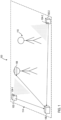
- FIG. 1 shows a VR system 100 with object detection in accordance with various examples, and describes some of the features of the independent claims.
- the VR system 100 includes a monitoring stations 102-1 and 102-2 (collectively referred to as monitoring stations 102), a VR headset 108, and an image processing device 106. While two monitoring stations 102 are shown in the VR system 100, some examples of the VR system 100 may include more or less than two monitoring stations 102.
- FIG. 1 depicts the image processing device 106 as separate from the VR headset 108 and the monitoring stations 102, in some implementations of the VR system 100 the image processing device 106 may a component of or integrated with the VR headset 108 or one of the monitoring stations 102.
- Each of the monitoring stations 102 includes a distinct image sensor.
- monitoring station 102-1 may include an imaging sensor 104-1.
- Monitoring station 102-2 may include an imaging sensor 104-2. Imaging sensors 104-1 and 104-2 may be collectively referred to as imaging sensor 104.
- the image sensor 104 may be an infra-red (IR) depth sensing camera, a camera that captures luma and/or chroma information, or other image sensor suitable for capturing images of objects in a VR operating environment.
- IR infra-red
- FIG. 1 monitoring stations 102 are disposed to capture images of the VR operating environment 114.
- the VR operating environment 114 is the physical area in which a user of the VR system 100, i.e., a user of the VR headset 108, interacts with the virtual world presented to the user via the VR headset 108.
- the VR headset 108 includes video display technology that displays images of the virtual world to the user of the VR headset 108.
- the monitoring stations 102 may be disposed at different locations in the VR operating environment 114 to capture images of the VR operating environment 114 from different angles.
- the image processing device 106 is communicatively coupled to the monitoring stations 102.
- the image processing device 106 may be communicatively coupled to the monitoring stations 102 via a wired or wireless communication link, such as a IEEE 802.11 wireless network, an IEEE 802.3 wired network, or any other wired or wireless communication technology that allows the images of the VR operating environment 114 captured by the monitoring stations 102 to be transferred from the monitoring stations 102 to the image processing device 106.
- the spatial relationship of the monitoring stations 102 may be known to the image processing device 106.
- the relative angle(s) of the optical center lines of the image sensors 104 of the monitoring stations 102 may be known to the image processing device 106. That is, the monitoring stations 102 may be disposed to view the VR operating environment 114 at a predetermined relative angle, or the angle at which the monitoring stations 102 are disposed relative to one another may be communicated to the image processing device 106.
- the image processing device 106 processes the images captured by the monitoring stations 102 to identify objects in the VR operating environment 114.
- the image processing device 106 may apply motion detection to detect objects in the VR operating environment 114 that may collide with the user of the VR headset 108. For example, the image processing device 106 may compare the time sequential images (e.g., video frames) of the VR operating environment 114 received from each monitoring station 102 to identify image to image changes that indicate movement of an object.
- a person 110 is moving in the VR operating environment 114.
- the person 110 is representative of any object that may be moving in the VR operating environment 114.
- the monitoring stations 102 capture images of the VR operating environment 114, and transmit the images to the image processing device 106.
- the image processing device 106 compares the images received from the monitoring station 102 and identifies differences in the images as motion of an object. For example, movement of the person 110 will cause differences in the images captured by the monitoring stations 102, and the image processing device 106 will identify the image to image difference as movement of the person 110.
- the image processing device 106 When the image processing device 106 detects an object in the VR operating environment, the image processing device 106 communicates to the VR headset 108 information regarding the detected object.
- the image processing device 106 is communicatively connected to the VR headset 108.
- the image processing device 106 may be communicatively coupled to the VR headset 108 via a wired or wireless communication link, such as a IEEE 802.11 wireless network, an IEEE 802.3 wired network, or any other wired or wireless communication technology that allows information to be transferred from the image processing device 106 to the VR headset 108.
- the image processing device 106 may determine the location (in three-dimensional space) of an object detected as moving (and pixels representing points of the object) in the images captured by each of the monitoring stations 102 at a given time. Using the relative locations of the monitoring stations 102 known by the image processing device 106, the image processing device 106 can determine the location of the detected object (e.g., determine the location of a point of the object identified in images captured by different monitoring stations 102) by applying triangulation. That is, the image processing device 106 may determine the location of a detected object in three-dimensional space by triangulating a common point found in multiple two-dimensional images captured by different monitoring stations 102 (e.g., monitoring station 102-1 and 102-2). The image processing device 106 may transmit location information for a detected object to the VR headset 108.
- the image processing device 106 may also determine the identity of an object detected in the VR operating environment 114. For example, on detection of an object in the VR operating environment 114, the image processing device 106 may apply a Viola-Jones object detection framework to identify the object based on the features of the object captured in an image. The image processing device 106 may transmit identity information (e.g., person, animal, etc.) for a detected object to the VR headset 108.
- identity information e.g., person, animal, etc.
- the VR headset 108 displays the information provided by the image processing device 106 for communication to a user. If the image processing device 106 renders the video displayed by the VR headset 108, then the image processing device 106 may include the information identifying a detected object in the video frames transmitted to the VR headset 108. If the VR headset 108 itself produces the video data displayed by the VR headset 108, then the VR headset 108 may receive the information about the detected object from the image processing device 106 and integrate the information in the video generated by the VR headset 108. Having been made aware of the presence of detected object, and optionally the objects location and/or identity, by the information presented via the VR headset 108, the user will not be surprised by the presence of the detected object in the VR operating environment and can avoid collision with the detected object.
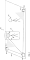
- FIG. 2 shows additional detail of the VR system 100 in accordance with various examples, and describes some of the features of the claims.
- the VR system 100 may also include one or more controllers 112.
- the controller 112 is an input device that the user of the VR headset 108 manipulates to interact with the virtual world.
- the controller 112 may be, for example, a handheld device that the user operates to digitally interact with virtual objects in the virtual world.
- the image processing device 106 identifies an area about the VR headset 108 and the controller 112 as corresponding to the user.
- the image processing device 106 defines an area 116 extending from above the VR headset 108 to the floor and to a maximum or predetermined extension of the controller 112 about a central axis corresponding to the user as representing the area occupied by the user of the VR system.
- the image processing device 106 disregards motion detected within the area 116 when detecting objects in the VR operating environment 114.
- the image processing device 106 detects motion outside the area 116 as corresponding to an object that may be of interest to the user of the VR system 100 while ignoring motion inside the area 116 with respect to object detection.
- Some implementations of the image processing device 106 may dynamically map the body and limbs of a user of the VR headset 108 to define an area within which motion is disregarded. For example, the image processing device 106 may determine the location of the controller(s) 112 knowing that the distal end of the user's arm is attached to a controller 112. The VR headset 108 identifies the location of the user's body and the user's legs are connected to the body. Using this information, the image processing device 106 may determine a dynamic amorphous boundary that defines an area within which motion is disregarded.
- FIG. 3 shows a block diagram of a monitoring station 102 for object detection in a VR system in accordance with various examples.
- the monitoring station 102 includes an image sensor 304 and a transmitter 302.
- the image sensor 304 may be a red-green-blue light sensor of any resolution suitable for detection of movement in the VR operating environment 114.
- the image sensor 304 may be an IR depth sensor that includes an IR projector and an IR camera.
- the IR projector may project a pattern of IR points and the IR camera may capture images of the points reflected from objects in the VR operating environment that can processed to determine distance.
- the image sensor 304 is communicatively coupled to the transmitter 302. Images captured by image sensor 304 are transferred to the transmitter 302, which transmits the images to the image processing device 106.
- the transmitter 302 may include circuitry to transmit the images via wired or wireless media.
- the monitoring station 102 may include additional components that have been omitted from FIG. 3 in the interest of clarity.
- the monitoring station 102 may include a processor coupled to the image sensor 304 and the transmitter 302, where the processor provides control and image transfer functionality in the monitoring station 102.
- FIG. 4 shows a block diagram of a monitoring station 102 for object detection in a VR system in accordance with various examples.
- the monitoring station 102 of FIG. 4 is similar to that shown in FIG. 3 and further includes headset and controller transducers 402.
- the headset and controller transducers 402 may generate optical timing signals that allow the location and orientation of the VR headset 108 and each VR controller 112 to be determined with sufficient specificity to facilitate accurate determination of the position of the VR headset 108 and the VR controller 112 in the VR operating environment 114.
- the headset and controller transducers 402 may include IR emitters that generate timed signals (e.g., a reference pulse and swept plane) for reception by sensors on the VR headset 108 and the VR controller 112.
- the location and orientation of the VR headset 108 and controller 112 can be determined based on which sensors of the VR headset 108 and controller 112 detect signals generated by the transducers 402 and relative timing of pulse and sweep detection.
- FIG. 5 shows a block diagram of an image processing device 106 for object detection in a VR system in accordance with various examples.
- the image processing device 106 includes a transceiver 502, a processor 504, and storage 506.
- the image processing device 106 may also include various components and systems that have been omitted from FIG. 5 in the interest of clarity.
- the image processing device 106 may include display systems, user interfaces, etc.
- the image processing device 106 may be implemented in a computer as known in the art.
- the image processing device 106 may be implemented using a desktop computer, a notebook computer, rack-mounted computer, a tablet computer or any other computing device suitable for performing the image processing operations described herein for detection of objects in the VR operating environment 114.
- the transceiver 502 communicatively couples the image processing device 106 to the monitoring stations 102 and the VR headset 108.
- the transceiver 502 may include a network adapter that connects the image processing device 106 to a wireless or wired network that provides communication between the monitoring stations 102 and the image processing device 106.
- a network may be based on any of a variety of networking standards (e.g., IEEE 802) or be proprietary to communication between devices of the VR system 100.
- the processor 504 is coupled to the transceiver 502.
- the processor 504 may include a general-purpose microprocessor, a digital signal processor, a microcontroller, a graphics processor, or other device capable of executing instructions retrieved from a computer-readable storage medium.
- Processor architectures generally include execution units (e.g., fixed point, floating point, integer, etc.), storage (e.g., registers, memory, etc.), instruction decoding, instruction and data fetching logic, peripherals (e.g., interrupt controllers, timers, direct memory access controllers, etc.), input/output systems (e.g., serial ports, parallel ports, etc.) and various other components and sub-systems.
- the storage 506 is a computer-readable medium that stores instructions and data for access and use by the processor 504.
- the storage 506 may include any of volatile storage such as random access memory, non-volatile storage (e.g., a hard drive, an optical storage device (e.g., CD or DVD), FLASH storage, read-only-memory), or combinations thereof.
- the storage 506 includes object detection 508, object identification 512, object location 514, object prioritization 516, and images 518.
- the images 518 include images of the VR operating environment 114 captured by the monitoring stations 102 and transferred to the image processing device 106 via the transceiver 502.
- the object detection 508, object identification 512, object location 514, and object prioritization 516 include instructions that are executed by the processor 504 to process the images 518.
- the objection detection 508 includes instructions that are executable by the processor 504 to detect objects in the VR operating environment 114.
- the objection detection 508 may include motion detection 510.
- the motion detection 510 includes instructions that are executable by the processor 504 to detect motion in the VR operating environment 114.
- the motion detection 510 may detect motion by identifying image to image changes in images 518, by identifying a difference between a reference image and a given one of the images 518, or by other motion detection processing.
- the object detection 508 ignores motion detected within the area 116 corresponding to a user of the VR headset 108.
- the object detection 508 may identify points associated with a detected object using edge detection. The presence of a detected object may be communicated to the VR headset 108 by the image processing device 106.
- the object location 514 includes instructions that are executable by the processor 504 to determine the three dimensional location of an object detected by the objection detection 508. For example, if the object detection 508 identifies an object in images 518 captured by different monitoring stations 102, then the object location 514 can determine the location of the object in the three dimensional VR operating environment 114 by triangulation based on the known locations of the monitoring stations 102 and the known angles between the optical centerlines of the image sensors 304 of the different monitoring stations 102. The location of the object may be communicated to the VR headset 108 by the image processing device 106.
- the object identification 512 includes instructions that are executable by the processor 504 to determine the identity of an object detected by the objection detection 508.
- the object identification 512 may include a Viola-Jones Framework trained to identify a variety of objects that may be present in the VR operating environment 114, such as people and pets.
- the pixels corresponding to the detected object may be processed by the Viola-Jones Framework to identify the object.
- the identity of the object may be communicated to the VR headset 108 by the image processing device 106.
- the object prioritization 516 includes instructions that are executable by the processor 504 to prioritize the object-related information provided to the VR headset 108 by the image processing device 106. Prioritization may be based on object size, distance between the object and the VR headset 108, object elevation, and/or other factors indicative of collision between the detected object and a user of the VR headset 108. The object prioritization 516 prioritizes a plurality of detected objects according to a risk of collision between the object and the user of the VR headset 108 and communicate information concerning the objects to the VR headset 108 in order of highest determined collision risk.
- the storage 506 may include additional logic that has been omitted from FIG. 5 in the interest of clarity.
- the storage 506 may include VR headset communication that includes instructions that are executable by the processor 504 to transfer information concerning a detected object (e.g., object presence, location, and/or identity) to the VR headset 108.
- the image processing device 106 may produce the video frames displayed by the VR headset 108.
- the image processing device 106 may include video rendering instructions that are executable by the processor 504 to generate the video frames displayed by the VR headset 108, and may include in the video frames information concerning a detected object.
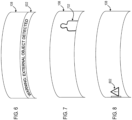
- FIGs. 6-8 show display of object detection information in the VR headset 108 in accordance with various examples.
- the displays of FIGs. 6-8 may be stereoscopic in practice, but are shown as monoscopic in FIGs. 6-8 to promote clarity.
- the VR headset 108 displays an object detection warning as a text field 602.
- the text field 602 may specify the location and identity of the object in addition to the presence of the object.
- the VR headset 108 displays an object detection warning as an outline 702 or silhouette of a detected object.
- the outline 702 of the object may correspond to the identity of the object determined by the object identification 512, and the location of the object in the display of the VR headset 108 may correspond to the location of the object determined by the object location 514.
- the VR headset 108 displays a warning symbol 802 indicating that an object has been detected and is to the left of the viewing field of the VR headset 108.
- Some implementations may combine the object information displays of FIGs. 6-8 .
- an object outside of the viewing area of the VR headset 108 may be indicated as per FIG. 8 , and as the VR headset 108 is turned towards the object an outline 702 or silhouette of the object may be displayed as per FIG. 7 .
- text display 602 may be combined with either the warning symbol 802 or the object outline 702 to provide additional information to the user of the VR headset 108.
- FIG. 9 shows a flow diagram for a method 900 for object detection in a VR system in accordance with various examples, and describes some of the features of the independent claims. Though depicted sequentially as a matter of convenience, at least some of the actions shown can be performed in a different order and/or performed in parallel. Additionally, some implementations may perform only some of the actions shown. In some implementations, at least some of the operations of the method 900 can be implemented as instructions stored in a storage device and executed by one or more processors.
- the monitoring stations 102 capture images of the VR operating environment 114.
- the monitoring stations 102 are disposed at different locations along the perimeter of the VR operating environment 114.
- the locations of the monitoring stations 102 and the angles of intersection of the optical centerlines of the image sensors 104 of the monitoring stations 102 may be known to the image processing device 106.
- the images captured by the monitoring stations 102 may include color information (chroma) and brightness information (luma), or may include only luma.
- the monitoring stations may capture images as a video stream. For example, the monitoring station 102 may capture images at a rate of 10, 20, 30, etc. images per second.
- the monitoring stations 102 transfer the captured images to the image processing device 106 for use in object detection.
- the image processing device 106 processes the images captured by the monitoring stations 102 to detect objects in the VR operating environment 114.
- the processing may include application of motion detection to identify an object in the VR operating environment 114.
- the image processing device 106 may detect motion by comparing two images and identifying differences between the two images.
- the two images may be images captured by the same monitoring station 102 (e.g., monitoring station 102-1) at different times.
- One of the images may be a reference image. Further, as explained with regard to FIG.
- the image processing device 106 may identify the VR headset 108 and/or a VR controller 112 in the images and ignore differences in the images (i.e., ignore motion) in a predetermined area 116 about the VR headset 108 and/or a VR controller 112 as attributable to movement of a user of the VR headset 108.
- the image processing device 106 has detected an object in the VR operating environment 114 and transmits information concerning the detected object to the VR headset 108.
- the information may include a notification of the objects presence in the VR operating environment 114.
- the information may be embedded in a video stream provided by the image processing device 106 for display by the VR headset 108, or provided separately from any video information transferred to the VR headset 108.
- the information may be transferred via a wired or wireless communication channel provided between the image processing device 106 and the VR headset 108.
- the communication channel may include a wired or wireless network in accordance with various networking standards.
- the VR headset 108 displays the information received from the image processing device 106 concerning the detected object.
- the information may be displayed in conjunction with a VR scene displayed by the VR headset 108.
- FIG. 10 shows a flow diagram for a method 1000 for object detection in a VR system in accordance with various examples. Though depicted sequentially as a matter of convenience, at least some of the actions shown can be performed in a different order and/or performed in parallel. Additionally, some implementations may perform only some of the actions shown. In some implementations, at least some of the operations of the method 1000 can be implemented as instructions stored in a storage device and executed by one or more processors.
- the monitoring stations 102 capture images of the VR operating environment 114.
- the monitoring stations 102 are disposed at different locations at the perimeter of the VR operating environment 114.
- the locations of the monitoring stations 102 and the angles of intersection of the optical centerlines of the image sensors 104 of the monitoring stations 102 may be known to the image processing device 106.
- the images captured by the monitoring stations 102 may include color information (chroma) and brightness information (luma), or may include only luma.
- the monitoring stations may capture images as a video stream. For example, the monitoring station 102 may capture images at a rate of 10, 20, 30, etc. images per second.
- the monitoring stations 102 transfer the captured images to the image processing device 106 for use in object detection.
- the image processing device 106 processes the images captured by the monitoring stations 102 to detect objects in the VR operating environment 114.
- the processing may include application of motion detection to identify an object in the VR operating environment 114.
- the image processing device 106 may detect motion by comparing two images and identifying differences between the two images.
- the two images may be images captured by the same monitoring station 102 at different times.
- One of the images may be a reference image.
- the image processing device106 may identify the VR headset 108 and/or a VR controller 112 in the images and ignore differences in the images (i.e., ignore motion) in a predetermined area 116 about the VR headset 108 and/or a VR controller 112 as attributable to movement of a user of the VR headset 108.
- the image processing device 106 processes the images captured by the monitoring stations 102 to determine the location of any detect objects in the VR operating environment 114.
- the location determination processing may include identifying the detected object in time coincident images captured by different monitoring stations 102, and applying triangulation to points of the detected object locate the object in three dimensions.
- the image processing device 106 processes the images captured by the monitoring stations 102 to determine the identity of any objects detected in the VR operating environment 114.
- the identify determination processing may include extracting and/or isolating an image of a detected object from an image captured by a monitoring station 102, and providing the image of the detected object to a Viola-Jones Framework.
- the Viola-Jones Framework may extract features from the image and apply one or more classifiers to identify the object.
- Various other object identification algorithms may be used in some implementations of the identity determination processing.
- the image processing device 106 prioritizes detected objects for presentation to the VR headset 108. Prioritization may be based on object size, distance between the object and the VR headset 108, object elevation, rate of movement towards the user, and/or other factors indicative of collision between the detected object and a user of the VR headset 108. Prioritization processing prioritizes a plurality of detected objects according to a risk of collision between the object and the user of the VR headset 108 and communicates information concerning the objects to the VR headset 108 in order of highest determined collision risk.
- the image processing device 106 has detected an object in the VR operating environment 114 and transmits information concerning the detected object to the VR headset 108.
- the information may include one or more notifications of the objects present in the VR operating environment 114, location of the detected objects in the VR operating environment 114, and identity of the detected objects.
- the information may be embedded in a video stream provided by the image processing device 106 for display by the VR headset 108, or provided separately from any video information transferred to the VR headset 108.
- the information may be transferred via a wired or wireless communication channel provided between the image processing device 106 and the VR headset 108.
- the communication channel may include a wired or wireless network in accordance with various networking standards.
- the VR headset 108 displays the information received from the image processing device 106 concerning the detected object to allow a user of the VR headset 108 to become aware of the detected object, and potentially avoid a collision with the detected object.
- the information may be displayed in conjunction with a VR scene displayed by the VR headset 108.
Landscapes
- Engineering & Computer Science (AREA)
- Physics & Mathematics (AREA)
- Theoretical Computer Science (AREA)
- General Physics & Mathematics (AREA)
- General Engineering & Computer Science (AREA)
- Computer Vision & Pattern Recognition (AREA)
- Multimedia (AREA)
- Human Computer Interaction (AREA)
- Optics & Photonics (AREA)
- User Interface Of Digital Computer (AREA)
- Controls And Circuits For Display Device (AREA)
Claims (10)
- Virtual-Reality-System, VR-System, umfassend:ein VR-Headset (108);einen VR-Controller (112);eine Vielzahl von Überwachungsstationen (102), die an verschiedenen Standorten angeordnet sind, wobei jede der Überwachungsstationen (102) einen eigenen Bildsensor (104, 304) umfasst, um Bilder des VR-Headsets (108) und einer Umgebung, in der das VR-Headset (108) verwendet wird, aufzunehmen;eine Bildverarbeitungsvorrichtung (106) zum:Verarbeiten der von den Überwachungsstationen (102) aufgenommenen Bilder, um eine Vielzahl von Objekten in der Umgebung zu erkennen;Priorisieren der Vielzahl erkannter Objekte entsprechend einem Kollisionsrisiko zwischen dem Objekt und dem Benutzer des VR-Headsets (108);Übertragen von Informationen an das VR-Headset (108), die eine Benachrichtigung über die Vielzahl erkannter Objekte in der Reihenfolge des höchsten ermittelten Kollisionsrisikos umfassen;Identifizieren eines Bereichs um das VR-Headset (108) und den VR-Controller (112) herum als dem Benutzer entsprechend, indem ein Bereich definiert wird, der sich von oberhalb des VR-Headsets (108) bis zum Boden und bis zu einer vorbestimmten Verlängerung des VR-Controllers (112) um eine dem Benutzer entsprechende Mittelachse erstreckt, als den vom Benutzer des VR-Systems eingenommenen Bereich darstellend, wobei die Bildverarbeitungsvorrichtung (106) dazu dient, beim Erkennen von Objekten in der VR-Betriebsumgebung innerhalb des Bereichs erkannte Bewegungen zu ignorieren; undErkennen der Objekte durch Erkennen von Bewegungen außerhalb des Bereichs.
- System nach Anspruch 1, wobei die Bildverarbeitungsvorrichtung (106) dazu dient, eine Bewegungserkennung anzuwenden, um die Objekte durch Erkennen von Bewegungen in der Umgebung zu erkennen.
- System nach Anspruch 1, wobei die Bildverarbeitungsvorrichtung (106) dazu dient, einen Standort eines Objekts relativ zu dem VR-Headset (108) auf der Basis von Bildern des Objekts zu bestimmen, die von der Vielzahl von Überwachungsstationen (102) aufgenommen wurden, und wobei die Informationen den Standort des Objekts relativ zum VR-Headset (108) umfassen.
- System nach Anspruch 1, wobei die Bildverarbeitungsvorrichtung (106) dazu dient, die Identität eines Objekts auf der Basis von Bildern des Objekts zu bestimmen, die von der Vielzahl von Überwachungsstationen (102) aufgenommen wurden, und die Informationen die Identität des Objekts umfassen.
- System nach Anspruch 1, wobei die Bildverarbeitungsvorrichtung dazu dient, die Vielzahl der erkannten Objekte nach dem Kollisionsrisiko auf der Basis einer Höhe des Objekts und/oder einer Geschwindigkeit der Bewegung in Richtung des Benutzers zu priorisieren.
- Verfahren, das umfasst:Aufnehmen, durch eine Vielzahl von Überwachungsstationen (102), von Bildern eines Virtual-Reality-Headsets, VR-Headsets, und einer Umgebung, in der das VR-Headset (108) betrieben wird, von einer Vielzahl unterschiedlicher Standorte aus;Verarbeiten der Bilder durch eine Bildverarbeitungsvorrichtung (106), um eine Vielzahl von Objekten in der Umgebung zu erkennen;Identifizieren, durch die Bildverarbeitungsvorrichtung (106), eines Bereichs um das VR-Headset (108) und eines VR-Controllers (112) als dem Benutzer entsprechend, durch Definieren eines Bereichs, der sich von oberhalb des VR-Headsets (108) bis zum Boden und bis zu einer vorbestimmten Verlängerung des VR-Controllers (112) um eine zentrale Achse, die dem Benutzer entspricht, erstreckt, als den Bereich darstellend, der von dem Benutzer des VR-Systems eingenommen wird; undIgnorieren, durch die Bildverarbeitungsvorrichtung (106), von innerhalb des Bereichs erkannten Bewegungen beim Erkennen von Objekten in der VR-Betriebsumgebung;Erkennen von Objekten durch Erkennen von Bewegungen außerhalb des Bereichs;Priorisieren, durch die Bildverarbeitungsvorrichtung (106), der Vielzahl erkannter Objekte entsprechend einem Kollisionsrisiko zwischen dem Objekt und dem Benutzer des VR-Headsets (108);Übertragen, durch die Bildverarbeitungsvorrichtung (106), von Informationen, die eine Benachrichtigung über die Objekte in der Reihenfolge des höchsten Kollisionsrisikos an das VR-Headset (108) umfassen; undAnzeigen, durch das VR-Headset (108), der Informationen in Verbindung mit einer VR-Szene.
- Verfahren nach Anspruch 6, das ferner das Bestimmen eines Standorts eines Objekts relativ zu dem VR-Headset (108) auf der Basis von Bildern des Objekts umfasst, die an der Vielzahl von unterschiedlichen Standorten aufgenommen wurden; wobei die Informationen den Standort des Objekts umfassen.
- Verfahren nach Anspruch 6, das ferner das Priorisieren der Vielzahl erkannter Objekte entsprechend dem Kollisionsrisiko auf der Basis von einer Objekthöhe und/oder einer Bewegungsgeschwindigkeit in Richtung des Benutzers umfasst.
- Nichtflüchtiges computerlesbares Medium, das mit Anweisungen codiert ist, um zu bewirken, dass das System nach Anspruch 1 das Verfahren nach Anspruch 6 ausführt.
- Computerlesbares Medium nach Anspruch 9, wobei die Anweisungen ferner dazu dienen, das System nach Anspruch 1 zu veranlassen zum:Bestimmen eines Standorts der Objekte relativ zu dem VR-Headset (108) basierend auf den Bildern der Objekte; undBestimmen der Identität eines erkannten Objekts basierend auf den Bildern des Objekts;wobei die Informationen den Standort des Objekts relativ zu dem VR-Headset (108) und die Identität des Objekts umfassen.
Applications Claiming Priority (1)
| Application Number | Priority Date | Filing Date | Title |
|---|---|---|---|
| PCT/US2017/028749 WO2018194637A1 (en) | 2017-04-21 | 2017-04-21 | Object detections for virtual reality |
Publications (3)
| Publication Number | Publication Date |
|---|---|
| EP3602496A1 EP3602496A1 (de) | 2020-02-05 |
| EP3602496A4 EP3602496A4 (de) | 2020-11-04 |
| EP3602496B1 true EP3602496B1 (de) | 2025-06-04 |
Family
ID=63856835
Family Applications (1)
| Application Number | Title | Priority Date | Filing Date |
|---|---|---|---|
| EP17906029.8A Active EP3602496B1 (de) | 2017-04-21 | 2017-04-21 | Objektnachweise für virtuelle realität |
Country Status (4)
| Country | Link |
|---|---|
| US (3) | US11270113B2 (de) |
| EP (1) | EP3602496B1 (de) |
| CN (1) | CN110692086A (de) |
| WO (1) | WO2018194637A1 (de) |
Families Citing this family (2)
| Publication number | Priority date | Publication date | Assignee | Title |
|---|---|---|---|---|
| US20230067239A1 (en) * | 2021-08-27 | 2023-03-02 | At&T Intellectual Property I, L.P. | Monitoring and response virtual assistant for a communication session |
| GB2618528A (en) * | 2022-05-04 | 2023-11-15 | Sony Interactive Entertainment Inc | Data processing apparatus and method |
Family Cites Families (17)
| Publication number | Priority date | Publication date | Assignee | Title |
|---|---|---|---|---|
| JPS586495B2 (ja) * | 1980-01-31 | 1983-02-04 | 三洋電機株式会社 | ジユ−サ |
| GB2301216A (en) | 1995-05-25 | 1996-11-27 | Philips Electronics Uk Ltd | Display headset |
| US6611622B1 (en) * | 1999-11-23 | 2003-08-26 | Microsoft Corporation | Object recognition system and process for identifying people and objects in an image of a scene |
| US9081177B2 (en) | 2011-10-07 | 2015-07-14 | Google Inc. | Wearable computer with nearby object response |
| JP5580855B2 (ja) | 2012-06-12 | 2014-08-27 | 株式会社ソニー・コンピュータエンタテインメント | 障害物回避装置および障害物回避方法 |
| US9908048B2 (en) * | 2013-06-08 | 2018-03-06 | Sony Interactive Entertainment Inc. | Systems and methods for transitioning between transparent mode and non-transparent mode in a head mounted display |
| US9630105B2 (en) | 2013-09-30 | 2017-04-25 | Sony Interactive Entertainment Inc. | Camera based safety mechanisms for users of head mounted displays |
| US9436872B2 (en) * | 2014-02-24 | 2016-09-06 | Hong Kong Applied Science and Technology Research Institute Company Limited | System and method for detecting and tracking multiple parts of an object |
| JP6627750B2 (ja) * | 2014-03-31 | 2020-01-08 | 日本電気株式会社 | 画像処理システム、画像処理装置、画像処理方法および記録媒体 |
| JP5777786B1 (ja) | 2014-09-12 | 2015-09-09 | キヤノン株式会社 | 情報処理装置、情報処理方法、プログラム |
| EP3215917B1 (de) | 2014-11-05 | 2023-10-11 | Valve Corporation | Sensorische rückkopplungssysteme und verfahren zur führung von benutzern in virtuellen realitätsumgebungen |
| US10002429B2 (en) | 2015-08-17 | 2018-06-19 | Samsung Electronics Co., Ltd. | Apparatus and method for notifying a virtual reality user of real world objects |
| US9934754B2 (en) * | 2015-09-30 | 2018-04-03 | Daqri, Llc | Dynamic sensor array for augmented reality system |
| WO2017120541A1 (en) * | 2016-01-06 | 2017-07-13 | Advanced Wireless Innovations Llc | Wireless security system |
| US9990778B2 (en) * | 2016-08-12 | 2018-06-05 | Tyco Safety Products Canada Ltd. | Notification system for virtual reality devices |
| US9972187B1 (en) * | 2016-11-13 | 2018-05-15 | Agility4Life | Biomechanical parameter determination for emergency alerting and health assessment |
| US10380875B1 (en) * | 2016-12-21 | 2019-08-13 | Alarm.Com Incorporated | Immersive virtual reality detection and alerting technology |
-
2017
- 2017-04-21 EP EP17906029.8A patent/EP3602496B1/de active Active
- 2017-04-21 CN CN201780089878.9A patent/CN110692086A/zh active Pending
- 2017-04-21 US US16/076,994 patent/US11270113B2/en active Active
- 2017-04-21 WO PCT/US2017/028749 patent/WO2018194637A1/en not_active Ceased
-
2022
- 2022-02-04 US US17/592,728 patent/US11861902B2/en active Active
-
2023
- 2023-10-20 US US18/491,548 patent/US20240054780A1/en not_active Abandoned
Also Published As
| Publication number | Publication date |
|---|---|
| US11861902B2 (en) | 2024-01-02 |
| EP3602496A1 (de) | 2020-02-05 |
| US20210201028A1 (en) | 2021-07-01 |
| EP3602496A4 (de) | 2020-11-04 |
| US20240054780A1 (en) | 2024-02-15 |
| US20220157055A1 (en) | 2022-05-19 |
| CN110692086A (zh) | 2020-01-14 |
| WO2018194637A1 (en) | 2018-10-25 |
| US11270113B2 (en) | 2022-03-08 |
Similar Documents
| Publication | Publication Date | Title |
|---|---|---|
| JP6979475B2 (ja) | ヘッドマウントディスプレイ追跡 | |
| US10474411B2 (en) | System and method for alerting VR headset user to real-world objects | |
| US10489981B2 (en) | Information processing device, information processing method, and program for controlling display of a virtual object | |
| US11614803B2 (en) | Individually interactive multi-view display system for non-stationary viewing locations and methods therefor | |
| US11195320B2 (en) | Feed-forward collision avoidance for artificial reality environments | |
| US11164378B1 (en) | Virtual reality detection and projection system for use with a head mounted display | |
| US20240054780A1 (en) | Object detections for virtual reality | |
| US20180075620A1 (en) | Method and system for determining a pose of camera | |
| CN121411450A (zh) | 用于对机器人进行初始化以沿着训练路线自主行进的系统和方法 | |
| EP3163407A1 (de) | Verfahren und vorrichtung zum alarmieren des benutzers einer kopfmontierten anzeige | |
| EP2697792A1 (de) | Vorrichtungen, systeme und verfahren zur bereitstellung einer bewegungsverfolgung mittels einer persönlichen anzeigevorrichtung | |
| WO2014071254A4 (en) | Wireless wrist computing and control device and method for 3d imaging, mapping, networking and interfacing | |
| CN110456905A (zh) | 定位跟踪方法、装置、系统及电子设备 | |
| WO2015093130A1 (ja) | 情報処理装置、情報処理方法およびプログラム | |
| KR20240121342A (ko) | 증강 현실을 위한 시스템들 및 방법들 | |
| CN110895676A (zh) | 动态对象跟踪 | |
| WO2015195652A1 (en) | System and method for providing graphical user interface | |
| US10642349B2 (en) | Information processing apparatus | |
| CN106384365B (zh) | 一种包含深度信息获取的扩增实境系统及其方法 | |
| WO2017163648A1 (ja) | 頭部装着装置 | |
| US20250371827A1 (en) | Information processing device, program, and information processing system | |
| WO2019111027A1 (en) | Method for creating virtual or augmented reality and system for creating virtual or augmented reality | |
| US20230358892A1 (en) | Position information acquisition system, position information acquisition method, and position information acquisition device | |
| Zhang et al. | Binocular vision sensor (Kinect)-based pedestrian following mobile robot | |
| US12067907B2 (en) | Position information acquisition device, head-mounted display, and position information acquisition method |
Legal Events
| Date | Code | Title | Description |
|---|---|---|---|
| STAA | Information on the status of an ep patent application or granted ep patent |
Free format text: STATUS: THE INTERNATIONAL PUBLICATION HAS BEEN MADE |
|
| PUAI | Public reference made under article 153(3) epc to a published international application that has entered the european phase |
Free format text: ORIGINAL CODE: 0009012 |
|
| STAA | Information on the status of an ep patent application or granted ep patent |
Free format text: STATUS: REQUEST FOR EXAMINATION WAS MADE |
|
| 17P | Request for examination filed |
Effective date: 20191021 |
|
| AK | Designated contracting states |
Kind code of ref document: A1 Designated state(s): AL AT BE BG CH CY CZ DE DK EE ES FI FR GB GR HR HU IE IS IT LI LT LU LV MC MK MT NL NO PL PT RO RS SE SI SK SM TR |
|
| AX | Request for extension of the european patent |
Extension state: BA ME |
|
| DAV | Request for validation of the european patent (deleted) | ||
| DAX | Request for extension of the european patent (deleted) | ||
| A4 | Supplementary search report drawn up and despatched |
Effective date: 20201002 |
|
| RIC1 | Information provided on ipc code assigned before grant |
Ipc: G06K 9/00 20060101ALN20200928BHEP Ipc: G06F 3/01 20060101AFI20200928BHEP Ipc: G06F 3/03 20060101ALI20200928BHEP |
|
| STAA | Information on the status of an ep patent application or granted ep patent |
Free format text: STATUS: EXAMINATION IS IN PROGRESS |
|
| 17Q | First examination report despatched |
Effective date: 20220318 |
|
| REG | Reference to a national code |
Ref country code: DE Ref legal event code: R079 Free format text: PREVIOUS MAIN CLASS: G06T0007700000 Ipc: G06F0003010000 Ref country code: DE Ref legal event code: R079 Ref document number: 602017089833 Country of ref document: DE Free format text: PREVIOUS MAIN CLASS: G06T0007700000 Ipc: G06F0003010000 |
|
| GRAP | Despatch of communication of intention to grant a patent |
Free format text: ORIGINAL CODE: EPIDOSNIGR1 |
|
| STAA | Information on the status of an ep patent application or granted ep patent |
Free format text: STATUS: GRANT OF PATENT IS INTENDED |
|
| RIC1 | Information provided on ipc code assigned before grant |
Ipc: G06F 3/03 20060101ALI20250204BHEP Ipc: G06F 3/01 20060101AFI20250204BHEP |
|
| INTG | Intention to grant announced |
Effective date: 20250220 |
|
| GRAS | Grant fee paid |
Free format text: ORIGINAL CODE: EPIDOSNIGR3 |
|
| GRAA | (expected) grant |
Free format text: ORIGINAL CODE: 0009210 |
|
| STAA | Information on the status of an ep patent application or granted ep patent |
Free format text: STATUS: THE PATENT HAS BEEN GRANTED |
|
| AK | Designated contracting states |
Kind code of ref document: B1 Designated state(s): AL AT BE BG CH CY CZ DE DK EE ES FI FR GB GR HR HU IE IS IT LI LT LU LV MC MK MT NL NO PL PT RO RS SE SI SK SM TR |
|
| REG | Reference to a national code |
Ref country code: GB Ref legal event code: FG4D |
|
| REG | Reference to a national code |
Ref country code: CH Ref legal event code: EP |
|
| REG | Reference to a national code |
Ref country code: DE Ref legal event code: R096 Ref document number: 602017089833 Country of ref document: DE |
|
| REG | Reference to a national code |
Ref country code: IE Ref legal event code: FG4D |
|
| REG | Reference to a national code |
Ref country code: NL Ref legal event code: MP Effective date: 20250604 |
|
| PG25 | Lapsed in a contracting state [announced via postgrant information from national office to epo] |
Ref country code: FI Free format text: LAPSE BECAUSE OF FAILURE TO SUBMIT A TRANSLATION OF THE DESCRIPTION OR TO PAY THE FEE WITHIN THE PRESCRIBED TIME-LIMIT Effective date: 20250604 Ref country code: ES Free format text: LAPSE BECAUSE OF FAILURE TO SUBMIT A TRANSLATION OF THE DESCRIPTION OR TO PAY THE FEE WITHIN THE PRESCRIBED TIME-LIMIT Effective date: 20250604 |
|
| REG | Reference to a national code |
Ref country code: LT Ref legal event code: MG9D |
|
| PG25 | Lapsed in a contracting state [announced via postgrant information from national office to epo] |
Ref country code: NO Free format text: LAPSE BECAUSE OF FAILURE TO SUBMIT A TRANSLATION OF THE DESCRIPTION OR TO PAY THE FEE WITHIN THE PRESCRIBED TIME-LIMIT Effective date: 20250904 Ref country code: GR Free format text: LAPSE BECAUSE OF FAILURE TO SUBMIT A TRANSLATION OF THE DESCRIPTION OR TO PAY THE FEE WITHIN THE PRESCRIBED TIME-LIMIT Effective date: 20250905 |
|
| PG25 | Lapsed in a contracting state [announced via postgrant information from national office to epo] |
Ref country code: PL Free format text: LAPSE BECAUSE OF FAILURE TO SUBMIT A TRANSLATION OF THE DESCRIPTION OR TO PAY THE FEE WITHIN THE PRESCRIBED TIME-LIMIT Effective date: 20250604 |
|
| PG25 | Lapsed in a contracting state [announced via postgrant information from national office to epo] |
Ref country code: BG Free format text: LAPSE BECAUSE OF FAILURE TO SUBMIT A TRANSLATION OF THE DESCRIPTION OR TO PAY THE FEE WITHIN THE PRESCRIBED TIME-LIMIT Effective date: 20250604 |
|
| PG25 | Lapsed in a contracting state [announced via postgrant information from national office to epo] |
Ref country code: HR Free format text: LAPSE BECAUSE OF FAILURE TO SUBMIT A TRANSLATION OF THE DESCRIPTION OR TO PAY THE FEE WITHIN THE PRESCRIBED TIME-LIMIT Effective date: 20250604 |
|
| PG25 | Lapsed in a contracting state [announced via postgrant information from national office to epo] |
Ref country code: RS Free format text: LAPSE BECAUSE OF FAILURE TO SUBMIT A TRANSLATION OF THE DESCRIPTION OR TO PAY THE FEE WITHIN THE PRESCRIBED TIME-LIMIT Effective date: 20250904 |
|
| PG25 | Lapsed in a contracting state [announced via postgrant information from national office to epo] |
Ref country code: LV Free format text: LAPSE BECAUSE OF FAILURE TO SUBMIT A TRANSLATION OF THE DESCRIPTION OR TO PAY THE FEE WITHIN THE PRESCRIBED TIME-LIMIT Effective date: 20250604 |
|
| PG25 | Lapsed in a contracting state [announced via postgrant information from national office to epo] |
Ref country code: NL Free format text: LAPSE BECAUSE OF FAILURE TO SUBMIT A TRANSLATION OF THE DESCRIPTION OR TO PAY THE FEE WITHIN THE PRESCRIBED TIME-LIMIT Effective date: 20250604 |
|
| PG25 | Lapsed in a contracting state [announced via postgrant information from national office to epo] |
Ref country code: PT Free format text: LAPSE BECAUSE OF FAILURE TO SUBMIT A TRANSLATION OF THE DESCRIPTION OR TO PAY THE FEE WITHIN THE PRESCRIBED TIME-LIMIT Effective date: 20251006 |
|
| REG | Reference to a national code |
Ref country code: AT Ref legal event code: MK05 Ref document number: 1800962 Country of ref document: AT Kind code of ref document: T Effective date: 20250604 |
|
| PG25 | Lapsed in a contracting state [announced via postgrant information from national office to epo] |
Ref country code: IS Free format text: LAPSE BECAUSE OF FAILURE TO SUBMIT A TRANSLATION OF THE DESCRIPTION OR TO PAY THE FEE WITHIN THE PRESCRIBED TIME-LIMIT Effective date: 20251004 |
|
| PG25 | Lapsed in a contracting state [announced via postgrant information from national office to epo] |
Ref country code: SM Free format text: LAPSE BECAUSE OF FAILURE TO SUBMIT A TRANSLATION OF THE DESCRIPTION OR TO PAY THE FEE WITHIN THE PRESCRIBED TIME-LIMIT Effective date: 20250604 Ref country code: AT Free format text: LAPSE BECAUSE OF FAILURE TO SUBMIT A TRANSLATION OF THE DESCRIPTION OR TO PAY THE FEE WITHIN THE PRESCRIBED TIME-LIMIT Effective date: 20250604 |
|
| PG25 | Lapsed in a contracting state [announced via postgrant information from national office to epo] |
Ref country code: CZ Free format text: LAPSE BECAUSE OF FAILURE TO SUBMIT A TRANSLATION OF THE DESCRIPTION OR TO PAY THE FEE WITHIN THE PRESCRIBED TIME-LIMIT Effective date: 20250604 |
|
| PG25 | Lapsed in a contracting state [announced via postgrant information from national office to epo] |
Ref country code: EE Free format text: LAPSE BECAUSE OF FAILURE TO SUBMIT A TRANSLATION OF THE DESCRIPTION OR TO PAY THE FEE WITHIN THE PRESCRIBED TIME-LIMIT Effective date: 20250604 |
|
| PG25 | Lapsed in a contracting state [announced via postgrant information from national office to epo] |
Ref country code: RO Free format text: LAPSE BECAUSE OF FAILURE TO SUBMIT A TRANSLATION OF THE DESCRIPTION OR TO PAY THE FEE WITHIN THE PRESCRIBED TIME-LIMIT Effective date: 20250604 Ref country code: SK Free format text: LAPSE BECAUSE OF FAILURE TO SUBMIT A TRANSLATION OF THE DESCRIPTION OR TO PAY THE FEE WITHIN THE PRESCRIBED TIME-LIMIT Effective date: 20250604 |
|
| PG25 | Lapsed in a contracting state [announced via postgrant information from national office to epo] |
Ref country code: IT Free format text: LAPSE BECAUSE OF FAILURE TO SUBMIT A TRANSLATION OF THE DESCRIPTION OR TO PAY THE FEE WITHIN THE PRESCRIBED TIME-LIMIT Effective date: 20250604 |
|
| REG | Reference to a national code |
Ref country code: DE Ref legal event code: R097 Ref document number: 602017089833 Country of ref document: DE |
|
| PLBE | No opposition filed within time limit |
Free format text: ORIGINAL CODE: 0009261 |
|
| STAA | Information on the status of an ep patent application or granted ep patent |
Free format text: STATUS: NO OPPOSITION FILED WITHIN TIME LIMIT |
|
| PG25 | Lapsed in a contracting state [announced via postgrant information from national office to epo] |
Ref country code: DK Free format text: LAPSE BECAUSE OF FAILURE TO SUBMIT A TRANSLATION OF THE DESCRIPTION OR TO PAY THE FEE WITHIN THE PRESCRIBED TIME-LIMIT Effective date: 20250604 |
|
| REG | Reference to a national code |
Ref country code: CH Ref legal event code: L10 Free format text: ST27 STATUS EVENT CODE: U-0-0-L10-L00 (AS PROVIDED BY THE NATIONAL OFFICE) Effective date: 20260416 |