EP3601724B1 - Wireline-deployed esp with self-supporting cable - Google Patents
Wireline-deployed esp with self-supporting cable Download PDFInfo
- Publication number
- EP3601724B1 EP3601724B1 EP18775159.9A EP18775159A EP3601724B1 EP 3601724 B1 EP3601724 B1 EP 3601724B1 EP 18775159 A EP18775159 A EP 18775159A EP 3601724 B1 EP3601724 B1 EP 3601724B1
- Authority
- EP
- European Patent Office
- Prior art keywords
- pumping system
- submersible pumping
- wireline
- power cable
- production tubing
- Prior art date
- Legal status (The legal status is an assumption and is not a legal conclusion. Google has not performed a legal analysis and makes no representation as to the accuracy of the status listed.)
- Active
Links
Images


Classifications
-
- F—MECHANICAL ENGINEERING; LIGHTING; HEATING; WEAPONS; BLASTING
- F04—POSITIVE - DISPLACEMENT MACHINES FOR LIQUIDS; PUMPS FOR LIQUIDS OR ELASTIC FLUIDS
- F04D—NON-POSITIVE-DISPLACEMENT PUMPS
- F04D13/00—Pumping installations or systems
- F04D13/02—Units comprising pumps and their driving means
- F04D13/06—Units comprising pumps and their driving means the pump being electrically driven
- F04D13/08—Units comprising pumps and their driving means the pump being electrically driven for submerged use
- F04D13/10—Units comprising pumps and their driving means the pump being electrically driven for submerged use adapted for use in mining bore holes
-
- E—FIXED CONSTRUCTIONS
- E21—EARTH OR ROCK DRILLING; MINING
- E21B—EARTH OR ROCK DRILLING; OBTAINING OIL, GAS, WATER, SOLUBLE OR MELTABLE MATERIALS OR A SLURRY OF MINERALS FROM WELLS
- E21B23/00—Apparatus for displacing, setting, locking, releasing or removing tools, packers or the like in boreholes or wells
-
- F—MECHANICAL ENGINEERING; LIGHTING; HEATING; WEAPONS; BLASTING
- F04—POSITIVE - DISPLACEMENT MACHINES FOR LIQUIDS; PUMPS FOR LIQUIDS OR ELASTIC FLUIDS
- F04D—NON-POSITIVE-DISPLACEMENT PUMPS
- F04D13/00—Pumping installations or systems
- F04D13/02—Units comprising pumps and their driving means
- F04D13/021—Units comprising pumps and their driving means containing a coupling
-
- F—MECHANICAL ENGINEERING; LIGHTING; HEATING; WEAPONS; BLASTING
- F04—POSITIVE - DISPLACEMENT MACHINES FOR LIQUIDS; PUMPS FOR LIQUIDS OR ELASTIC FLUIDS
- F04D—NON-POSITIVE-DISPLACEMENT PUMPS
- F04D13/00—Pumping installations or systems
- F04D13/02—Units comprising pumps and their driving means
- F04D13/06—Units comprising pumps and their driving means the pump being electrically driven
- F04D13/0693—Details or arrangements of the wiring
-
- F—MECHANICAL ENGINEERING; LIGHTING; HEATING; WEAPONS; BLASTING
- F04—POSITIVE - DISPLACEMENT MACHINES FOR LIQUIDS; PUMPS FOR LIQUIDS OR ELASTIC FLUIDS
- F04D—NON-POSITIVE-DISPLACEMENT PUMPS
- F04D13/00—Pumping installations or systems
- F04D13/02—Units comprising pumps and their driving means
- F04D13/06—Units comprising pumps and their driving means the pump being electrically driven
- F04D13/08—Units comprising pumps and their driving means the pump being electrically driven for submerged use
- F04D13/086—Units comprising pumps and their driving means the pump being electrically driven for submerged use the pump and drive motor are both submerged
-
- F—MECHANICAL ENGINEERING; LIGHTING; HEATING; WEAPONS; BLASTING
- F04—POSITIVE - DISPLACEMENT MACHINES FOR LIQUIDS; PUMPS FOR LIQUIDS OR ELASTIC FLUIDS
- F04D—NON-POSITIVE-DISPLACEMENT PUMPS
- F04D29/00—Details, component parts, or accessories
- F04D29/60—Mounting; Assembling; Disassembling
- F04D29/605—Mounting; Assembling; Disassembling specially adapted for liquid pumps
-
- H—ELECTRICITY
- H01—ELECTRIC ELEMENTS
- H01B—CABLES; CONDUCTORS; INSULATORS; SELECTION OF MATERIALS FOR THEIR CONDUCTIVE, INSULATING OR DIELECTRIC PROPERTIES
- H01B7/00—Insulated conductors or cables characterised by their form
- H01B7/04—Flexible cables, conductors, or cords, e.g. trailing cables
- H01B7/046—Flexible cables, conductors, or cords, e.g. trailing cables attached to objects sunk in bore holes, e.g. well drilling means, well pumps
-
- H—ELECTRICITY
- H01—ELECTRIC ELEMENTS
- H01B—CABLES; CONDUCTORS; INSULATORS; SELECTION OF MATERIALS FOR THEIR CONDUCTIVE, INSULATING OR DIELECTRIC PROPERTIES
- H01B7/00—Insulated conductors or cables characterised by their form
- H01B7/17—Protection against damage caused by external factors, e.g. sheaths or armouring
- H01B7/18—Protection against damage caused by wear, mechanical force or pressure; Sheaths; Armouring
- H01B7/22—Metal wires or tapes, e.g. made of steel
- H01B7/221—Longitudinally placed metal wires or tapes
- H01B7/223—Longitudinally placed metal wires or tapes forming part of a high tensile strength core
Definitions
- This invention relates generally to the production of hydrocarbons from a subterranean formation using an electric submersible pumping system, and more particularly, but not by way of limitation, to unconventional systems for deploying an electric submersible pumping system within a wellbore.
- EP 0 208 035 A1 discloses a submersible pumping system for pumping cryogenic liquid from a reservoir in which an electrically powered motor / pump unit is located at the bottom of a fluid transmitting casing in the reservoir.
- the motor / pump unit is electrically connected to a power source and to ground by flexible electrical and ground conduits and is raised and lowered through the casing by support and lift cables.
- the flexible conduits and support cable are arranged within a flexible sheath.
- US 2005/047872 A1 discloses a deepwell reel.
- US 2013/341033 A1 discloses a diffuser for a cable suspended dewatering pumping system.
- US 4 921 438 A discloses a wet connector.
- Submersible pumping systems are often deployed into wells to recover petroleum fluids from subterranean reservoirs.
- the submersible pumping system includes a number of components, including one or more electric motors coupled to one or more pumps.
- Each of the components and sub-components in a submersible pumping system is engineered to withstand the inhospitable downhole environment, which includes wide ranges of temperature, pressure and corrosive well fluids.
- the power cable is banded and supported by the wireline because the power cable cannot support its own weight. If the power cable is supported by the wireline, the wireline cannot be removed from the wellbore during use of the submersible pumping system. After prolonged exposure to corrosive wellbore chemicals, the wireline may corrode, fail and risk retrieval of the electric submersible pumping system.
- the invention includes a method of deploying and retrieving a submersible pumping system in production tubing within a wellbore according to claim 1.
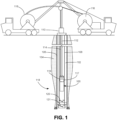
- FIG. 1 shows an elevational view of an electric submersible pumping system 100 being deployed in a wellbore 102 within a subterranean formation 104.
- the wellbore 102 includes a casing 106, production tubing 108 and a wellhead assembly 110.
- the pumping system 100 includes an electric motor and a pump driven by the electric motor.
- Electric power is supplied to the pumping system 100 through a self-supporting power cable 112.
- the power cable 112 is attached to the discharge end of the pump within the pumping system 100 and the cable runs along the outside of the pump to the motor.
- the motor is placed above the pump within the pumping system 100 and the power cable 112 is connected directly to the motor.
- the pumping system 100 may include additional components.
- the pumping system 100 may include a seal section, gas separators, sensor modules and other components known in the art.
- the pumping system 100 is deployed within the production tubing 108 with a wireline 114.
- the wireline 114 and power cable 112 are controllably extended into the wellbore 102 from one or more spools 116 located at the surface.
- the spools 116 may be mounted on mobile cranes (as depicted in FIG. 1 ). Similarly, the spools 116 can be mounted in a fixed position relative to the wellhead assembly 110.
- the pumping system 100 is depicted in use with an inland wellbore 102, it will be appreciated that the pumping system 100 can also be used and deployed in offshore applications.
- the production tubing 108 includes a landing assembly 118 disposed within the production tubing 108 to support the pumping system 100.
- the landing assembly 118 comprises a landing collar 117 that catches a corresponding flange 119 on the pumping system 100. In this way, the pumping system 100 hangs from the landing collar 117.
- the landing assembly 118 comprises a landing nipple disposed near the lower end of the production tubing 108.
- the use of an upper landing assembly 118 places the pumping system 100 in under a tension load, while the use of a lower landing assembly 118 will cause the weight of the pumping system 100 to be carried as a compressive load.
- the use of the lower landing assembly 118 will permit the deployment of pumping systems 100 that closely approximate the size of the production tubing 108 because the pumping system 100 does not need to extend through a landing collar.
- the landing assembly 118 provides support for the pumping system 100 and may include a deep set subsurface safety valve (SSSV) 120.
- the subsurface safety valve 120 is designed to be fail-safe, so that the wellbore 102 is isolated in the event of any system failure or damage to the surface production-control facilities.
- a flow control valve 121 can be positioned below the subsurface safety valve 120 can be selectively adjusted to permit flow into the production tubing 108 from the wellbore 102.
- the wireline 114 can be retrieved from the wellbore 102.
- the self-supporting power cable 112 remains connected to the pumping system 100 and unconnected to the production tubing 108. Because the power cable 112 is not banded to the wireline 114 for support, the wireline 114 can be removed from the wellbore to prevent corrosion of the wireline 114. Additionally, because the power cable 112 is connected to the pumping system 100 before deployment, the power cable 112 and pumping system 110 do not make a wet connection within the wellbore 102 The procedure described above in this paragraph is however not according to the claimed invention.
- the pumping system 100 is lowered to the landing assembly 118 with only the wireline 114 attached to the pumping system 100.
- the wireline 114 is retrieved from the wellbore 102.
- the power cable 112 is then lowered through the wellbore 102 and connected in situ to the pumping system 100. Extending the wireline 114 and power cable 112 into the wellbore 102 at different times simplifies the construction of the wellhead assembly 110.
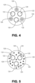
- the power cable 112 includes three copper conductors 122 configured to deliver electrical power to the motor within the pumping system 100.
- the conductors 122 include an insulating sheath 124.
- the insulating sheath may be constructed from polypropylene or other polymer that exhibits favorable stability under elevated temperatures.
- the power cable 112 further includes three braided steel cables 126 that provide tensile strength to the power cable 112.
- the power cable 112 includes a larger number of smaller braided steel cables 126.
- the braided steel cables 126 may be oriented such that the individual strands within some of the steel cables 126 are wound in opposite direction to the strands in other steel conductors to minimize torsional forces when the braided steel cables 126 are exposed to tension.
- the power cable 112 includes an abrasion resistant external jacket 128.
- the jacket 128 can be constructed from a thermally stable polymer.
- the self-supporting power cable 112 generally includes both electrical conductors and strength members that support the weight of the power cable 112 in the wellbore 102.
- the wireline 114 is used to deploy the pumping system 100, according to the invention, the power cable 112 is sufficiently strong to reliably support the combined weight of the pumping system 100 and the power cable 112. Under these circumstances, the pumping system 100 is retrieved from the production tubing 108 with only the power cable 112.
Landscapes
- Engineering & Computer Science (AREA)
- Mechanical Engineering (AREA)
- General Engineering & Computer Science (AREA)
- Mining & Mineral Resources (AREA)
- Life Sciences & Earth Sciences (AREA)
- Geology (AREA)
- Physics & Mathematics (AREA)
- Environmental & Geological Engineering (AREA)
- Fluid Mechanics (AREA)
- General Life Sciences & Earth Sciences (AREA)
- Geochemistry & Mineralogy (AREA)
- Structures Of Non-Positive Displacement Pumps (AREA)
Description
- This invention relates generally to the production of hydrocarbons from a subterranean formation using an electric submersible pumping system, and more particularly, but not by way of limitation, to unconventional systems for deploying an electric submersible pumping system within a wellbore.
-
EP 0 208 035 A1 discloses a submersible pumping system for pumping cryogenic liquid from a reservoir in which an electrically powered motor / pump unit is located at the bottom of a fluid transmitting casing in the reservoir. The motor / pump unit is electrically connected to a power source and to ground by flexible electrical and ground conduits and is raised and lowered through the casing by support and lift cables. The flexible conduits and support cable are arranged within a flexible sheath.US 2005/047872 A1 discloses a deepwell reel.US 2013/341033 A1 discloses a diffuser for a cable suspended dewatering pumping system.US 4 921 438 A discloses a wet connector. - Submersible pumping systems are often deployed into wells to recover petroleum fluids from subterranean reservoirs. Typically, the submersible pumping system includes a number of components, including one or more electric motors coupled to one or more pumps. Each of the components and sub-components in a submersible pumping system is engineered to withstand the inhospitable downhole environment, which includes wide ranges of temperature, pressure and corrosive well fluids.
- Conventional electric submersible pumping systems are connected to surface facilities through rigid production tubing. The pumping system and tubing are often run inside of a cased wellbore and the production fluids are pumped to the surface through the production tubing. Although widely adopted, the use of rigid production tubing presents several deficiencies. In particular, the use of long lengths of rigid production tubing requires a workover rig with sufficient height to retrieve and deploy the long sections of production tubing. Workover rigs are often expensive and difficult to source.
- As an alternative to the use of rigid production tubing, pump manufacturers have designed systems in which an electric submersible pumping system is installed within the wellbore using a wireline deployment system. These prior art systems suffer from two significant deficiencies. First, many prior art wireline deployment systems have included a powered docking assembly at the lower end of the production tubing. In these systems, the power cable is banded to the production tubing and remains in the wellbore with the production tubing. The electric submersible pumping system is then lowered by wireline to the powered docking assembly. The connection between the docking assembly and the electric submersible pumping system is a "wet connection" that is subject to failure.
- Second, in some prior art wireline deployment systems, the power cable is banded and supported by the wireline because the power cable cannot support its own weight. If the power cable is supported by the wireline, the wireline cannot be removed from the wellbore during use of the submersible pumping system. After prolonged exposure to corrosive wellbore chemicals, the wireline may corrode, fail and risk retrieval of the electric submersible pumping system.
- There is, therefore, a need for an improved system and method for deploying an electric submersible pumping system by wireline within a subterranean well. It is to this and other deficiencies in the prior art that the present invention is directed.
- In an aspect, the invention includes a method of deploying and retrieving a submersible pumping system in production tubing within a wellbore according to claim 1.
-
-
FIG. 1 is an elevational view of the deployment of an electric submersible pumping system with a wireline deployment system with a first landing assembly. -
FIG. 2 is an elevational view of the deployment of an electric submersible pumping system with a wireline deployment system with a second landing assembly. -
FIG. 3 is an elevational view of an electric submersible pumping system deployed with a wireline deployment system. -
FIG. 4 is a cross-sectional view of a first embodiment of the self-supporting cable. -
FIG. 5 is a cross-sectional view of a second embodiment of the self-supporting cable. - In accordance with exemplary embodiments of the present invention,
FIG. 1 shows an elevational view of an electricsubmersible pumping system 100 being deployed in awellbore 102 within asubterranean formation 104. Thewellbore 102 includes acasing 106,production tubing 108 and awellhead assembly 110. Thepumping system 100 includes an electric motor and a pump driven by the electric motor. - Electric power is supplied to the
pumping system 100 through a self-supportingpower cable 112. In the embodiments depicted inFIGS. 1 and2 , thepower cable 112 is attached to the discharge end of the pump within thepumping system 100 and the cable runs along the outside of the pump to the motor. In other embodiments, the motor is placed above the pump within thepumping system 100 and thepower cable 112 is connected directly to the motor. It will be appreciated that thepumping system 100 may include additional components. For example, thepumping system 100 may include a seal section, gas separators, sensor modules and other components known in the art. - The
pumping system 100 is deployed within theproduction tubing 108 with awireline 114. Thewireline 114 andpower cable 112 are controllably extended into thewellbore 102 from one ormore spools 116 located at the surface. Thespools 116 may be mounted on mobile cranes (as depicted inFIG. 1 ). Similarly, thespools 116 can be mounted in a fixed position relative to thewellhead assembly 110. Although thepumping system 100 is depicted in use with aninland wellbore 102, it will be appreciated that thepumping system 100 can also be used and deployed in offshore applications. - The
production tubing 108 includes alanding assembly 118 disposed within theproduction tubing 108 to support thepumping system 100. In the embodiment depicted inFIG. 1 , thelanding assembly 118 comprises alanding collar 117 that catches acorresponding flange 119 on thepumping system 100. In this way, thepumping system 100 hangs from thelanding collar 117. In contrast, in the embodiment depicted inFIG. 2 , thelanding assembly 118 comprises a landing nipple disposed near the lower end of theproduction tubing 108. The use of anupper landing assembly 118 places thepumping system 100 in under a tension load, while the use of alower landing assembly 118 will cause the weight of thepumping system 100 to be carried as a compressive load. The use of thelower landing assembly 118 will permit the deployment ofpumping systems 100 that closely approximate the size of theproduction tubing 108 because thepumping system 100 does not need to extend through a landing collar. - The
landing assembly 118 provides support for thepumping system 100 and may include a deep set subsurface safety valve (SSSV) 120. Thesubsurface safety valve 120 is designed to be fail-safe, so that thewellbore 102 is isolated in the event of any system failure or damage to the surface production-control facilities. Below thesubsurface safety valve 120, Aflow control valve 121 can be positioned below thesubsurface safety valve 120 can be selectively adjusted to permit flow into theproduction tubing 108 from thewellbore 102. - As illustrated in
FIG. 3 , once thepumping system 100 has been engaged with thelanding assembly 118, thewireline 114 can be retrieved from thewellbore 102. Significantly, the self-supportingpower cable 112 remains connected to thepumping system 100 and unconnected to theproduction tubing 108. Because thepower cable 112 is not banded to thewireline 114 for support, thewireline 114 can be removed from the wellbore to prevent corrosion of thewireline 114. Additionally, because thepower cable 112 is connected to thepumping system 100 before deployment, thepower cable 112 andpumping system 110 do not make a wet connection within thewellbore 102 The procedure described above in this paragraph is however not according to the claimed invention. - According to the invention, the
pumping system 100 is lowered to thelanding assembly 118 with only thewireline 114 attached to thepumping system 100. Once thepumping system 100 is supported by thelanding assembly 118, thewireline 114 is retrieved from thewellbore 102. Thepower cable 112 is then lowered through thewellbore 102 and connected in situ to thepumping system 100. Extending thewireline 114 andpower cable 112 into thewellbore 102 at different times simplifies the construction of thewellhead assembly 110. - Turning to
FIGS. 4 and 5 , shown therein are perspective views, respectively, of alternate embodiments of the self-supportingpower cable 112. In the embodiment depicted inFIG. 4 , thepower cable 112 includes threecopper conductors 122 configured to deliver electrical power to the motor within thepumping system 100. Theconductors 122 include an insulatingsheath 124. The insulating sheath may be constructed from polypropylene or other polymer that exhibits favorable stability under elevated temperatures. In this embodiment, thepower cable 112 further includes three braidedsteel cables 126 that provide tensile strength to thepower cable 112. In the embodiment depicted inFIG. 5 , thepower cable 112 includes a larger number of smallerbraided steel cables 126. The braidedsteel cables 126 may be oriented such that the individual strands within some of thesteel cables 126 are wound in opposite direction to the strands in other steel conductors to minimize torsional forces when the braidedsteel cables 126 are exposed to tension. In both embodiments, thepower cable 112 includes an abrasion resistantexternal jacket 128. Thejacket 128 can be constructed from a thermally stable polymer. - Thus, the self-supporting
power cable 112 generally includes both electrical conductors and strength members that support the weight of thepower cable 112 in thewellbore 102. Although thewireline 114 is used to deploy thepumping system 100, according to the invention, thepower cable 112 is sufficiently strong to reliably support the combined weight of thepumping system 100 and thepower cable 112. Under these circumstances, thepumping system 100 is retrieved from theproduction tubing 108 with only thepower cable 112. - It is to be understood that even though numerous characteristics and advantages of various embodiments of the present invention have been set forth in the foregoing description, together with details of the structure and functions of various embodiments of the invention, this disclosure is illustrative only, and changes may be made in detail, especially in matters of structure and arrangement of parts and steps within the scope of the invention which is defined by the following claims.
Claims (3)
- A method of deploying and retrieving a submersible pumping system (100) in production tubing (108) within a wellbore (102), the method comprising the steps of:connecting a wireline (114) to the submersible pumping system (100);lowering the submersible pumping system (100) into the production tubing (108), wherein the weight of the submersible pumping system (100) is borne by the wireline (114) during the descent;locating the submersible pumping system (100) on a landing assembly (118);disconnecting the wireline (114) from the submersible pumping system (100);retrieving the wireline (114) from the submersible pumping system (100);lowering a self-supporting power cable (112) to the submersible pumping system (100);connecting the self-supporting power cable (112) to the submersible pumping system (100); andproviding electric current to the submersible pumping system (100) through the self-supporting power cable (112);characterized by retrieving the submersible pumping system (100) from the wellbore (102) comprising the step of lifting the submersible pumping system (100) with the self-supporting power cable (112).
- The method of claim 1, wherein the step of locating the submersible pumping system (100) on a landing assembly (118) comprises contacting a landing flange near an upper end on the submersible pumping system (100) on a landing collar within the production tubing (108).
- The method of claim 1, wherein the step of locating the submersible pumping system (100) on a landing assembly (118) comprises contacting a landing assembly (118) near a lower end of the production tubing (108) with a lower end of the submersible pumping system (100).
Applications Claiming Priority (2)
| Application Number | Priority Date | Filing Date | Title |
|---|---|---|---|
| US201762477935P | 2017-03-28 | 2017-03-28 | |
| PCT/US2018/024977 WO2018183584A1 (en) | 2017-03-28 | 2018-03-28 | Wireline-deployed esp with self-supporting cable |
Publications (3)
| Publication Number | Publication Date |
|---|---|
| EP3601724A1 EP3601724A1 (en) | 2020-02-05 |
| EP3601724A4 EP3601724A4 (en) | 2020-12-23 |
| EP3601724B1 true EP3601724B1 (en) | 2024-10-23 |
Family
ID=63669109
Family Applications (1)
| Application Number | Title | Priority Date | Filing Date |
|---|---|---|---|
| EP18775159.9A Active EP3601724B1 (en) | 2017-03-28 | 2018-03-28 | Wireline-deployed esp with self-supporting cable |
Country Status (5)
| Country | Link |
|---|---|
| US (1) | US11085260B2 (en) |
| EP (1) | EP3601724B1 (en) |
| BR (1) | BR112019020109B1 (en) |
| SA (1) | SA519410201B1 (en) |
| WO (1) | WO2018183584A1 (en) |
Families Citing this family (4)
| Publication number | Priority date | Publication date | Assignee | Title |
|---|---|---|---|---|
| PL3222617T3 (en) | 2009-03-19 | 2023-01-02 | The Johns Hopkins University | TARGETING COMPOUNDS IN PSMA AND THEIR APPLICATIONS |
| US20180009767A9 (en) | 2009-03-19 | 2018-01-11 | The Johns Hopkins University | Psma targeted fluorescent agents for image guided surgery |
| WO2023177648A1 (en) * | 2022-03-14 | 2023-09-21 | Baker Hughes Oilfield Operations Llc | Esp with improved deployment for live intervention |
| US12366148B2 (en) | 2022-09-07 | 2025-07-22 | Baker Hughes Oilfield Operations Llc | System and method for deploying ESP on coiled tubing |
Citations (2)
| Publication number | Priority date | Publication date | Assignee | Title |
|---|---|---|---|---|
| GB1117379A (en) * | 1965-08-27 | 1968-06-19 | John Keller Henderson | Submersible electrical connector |
| US4921438A (en) * | 1989-04-17 | 1990-05-01 | Otis Engineering Corporation | Wet connector |
Family Cites Families (14)
| Publication number | Priority date | Publication date | Assignee | Title |
|---|---|---|---|---|
| US3853430A (en) * | 1972-08-08 | 1974-12-10 | Trw Inc | Cable-suspended, liner-supported submersible pump installation with locking discharge head |
| US4440221A (en) * | 1980-09-15 | 1984-04-03 | Otis Engineering Corporation | Submergible pump installation |
| DE3314051C1 (en) * | 1983-04-19 | 1984-08-16 | Albert 5204 Lohmar Blum | Lifting device for electric submersible pump units |
| NO853191L (en) * | 1985-06-05 | 1986-12-08 | Carter Co J C | SUBMITTED PUMP SYSTEM WITH MULTI-FUNCTION CABLE. |
| US5145007A (en) * | 1991-03-28 | 1992-09-08 | Camco International Inc. | Well operated electrical pump suspension method and system |
| SE506432C2 (en) * | 1994-01-04 | 1997-12-15 | Flygt Ab Itt | Method and arrangement for lifting / lowering a load provided with guide rope |
| US20050047872A1 (en) | 2003-09-03 | 2005-03-03 | Baugh Benton F. | Deepwell reel |
| GB0901542D0 (en) * | 2009-01-30 | 2009-03-11 | Artificial Lift Co Ltd | Downhole electric pumps |
| US8443900B2 (en) * | 2009-05-18 | 2013-05-21 | Zeitecs B.V. | Electric submersible pumping system and method for dewatering gas wells |
| WO2011106513A2 (en) * | 2010-02-24 | 2011-09-01 | Schlumberger Canada Limited | Permanent cable for submersible pumps in oil well applications |
| WO2011150213A2 (en) | 2010-05-28 | 2011-12-01 | Schlumberger Canada Limited | Deployment of downhole pump using a cable |
| US9255457B2 (en) | 2012-04-18 | 2016-02-09 | Schlumberger Technology Corporation | Deep deployment system for electric submersible pumps |
| US9482078B2 (en) | 2012-06-25 | 2016-11-01 | Zeitecs B.V. | Diffuser for cable suspended dewatering pumping system |
| US9976392B2 (en) * | 2015-01-02 | 2018-05-22 | Saudi Arabian Oil Company | Hydraulically assisted deployed ESP system |
-
2018
- 2018-03-28 EP EP18775159.9A patent/EP3601724B1/en active Active
- 2018-03-28 US US15/939,126 patent/US11085260B2/en active Active
- 2018-03-28 BR BR112019020109-2A patent/BR112019020109B1/en active IP Right Grant
- 2018-03-28 WO PCT/US2018/024977 patent/WO2018183584A1/en not_active Ceased
-
2019
- 2019-09-26 SA SA519410201A patent/SA519410201B1/en unknown
Patent Citations (2)
| Publication number | Priority date | Publication date | Assignee | Title |
|---|---|---|---|---|
| GB1117379A (en) * | 1965-08-27 | 1968-06-19 | John Keller Henderson | Submersible electrical connector |
| US4921438A (en) * | 1989-04-17 | 1990-05-01 | Otis Engineering Corporation | Wet connector |
Also Published As
| Publication number | Publication date |
|---|---|
| EP3601724A4 (en) | 2020-12-23 |
| US20180283384A1 (en) | 2018-10-04 |
| SA519410201B1 (en) | 2022-06-01 |
| WO2018183584A1 (en) | 2018-10-04 |
| BR112019020109B1 (en) | 2023-11-07 |
| BR112019020109A2 (en) | 2020-05-05 |
| US11085260B2 (en) | 2021-08-10 |
| EP3601724A1 (en) | 2020-02-05 |
Similar Documents
| Publication | Publication Date | Title |
|---|---|---|
| US9151131B2 (en) | Power and control pod for a subsea artificial lift system | |
| US7640993B2 (en) | Method of deploying and powering an electrically driven in a well | |
| US9166352B2 (en) | Downhole electrical coupler for electrically operated wellbore pumps and the like | |
| EP3289176B1 (en) | Method and system for deploying an electrical load device in a wellbore | |
| US8851165B2 (en) | Compact cable suspended pumping system for lubricator deployment | |
| CA2375808C (en) | Method of deploying an electrically driven fluid transducer system in a well | |
| US20130062050A1 (en) | Mating unit enabling the deployment of a modular electrically driven device in a well | |
| US11746630B2 (en) | Deployment of a modular electrically driven pump in a well | |
| US11085260B2 (en) | Wireline-deployed ESP with self-supporting cable | |
| WO2014028553A1 (en) | Subsea production system with downhole equipment suspension system | |
| CN110234836B (en) | Covered ESP | |
| US20170051592A1 (en) | System and Method for Powering and Deploying an Electric Submersible Pump | |
| EP2315906B1 (en) | Load bearing assembly | |
| US8813839B2 (en) | Method of deploying and powering an electrically driven device in a well | |
| US12540534B2 (en) | ESP with improved deployment for live intervention | |
| CN110168189B (en) | Underground hanger for umbilical cable deployment type electric submersible pump | |
| US10975630B1 (en) | Expansion tubing joint with extendable cable | |
| GB2478108A (en) | Method of deploying and powering an electrically driven device in a well | |
| GB2484331A (en) | Modular electrically driven device in a well | |
| AU2013207634B2 (en) | Power and control pod for a subsea artificial lift system | |
| EP0881355A2 (en) | System for deploying an electrical submersible pump within a wellbore | |
| CA2731039A1 (en) | Method of deploying and powering an electrically driven device in a well |
Legal Events
| Date | Code | Title | Description |
|---|---|---|---|
| STAA | Information on the status of an ep patent application or granted ep patent |
Free format text: STATUS: THE INTERNATIONAL PUBLICATION HAS BEEN MADE |
|
| PUAI | Public reference made under article 153(3) epc to a published international application that has entered the european phase |
Free format text: ORIGINAL CODE: 0009012 |
|
| STAA | Information on the status of an ep patent application or granted ep patent |
Free format text: STATUS: REQUEST FOR EXAMINATION WAS MADE |
|
| 17P | Request for examination filed |
Effective date: 20191024 |
|
| AK | Designated contracting states |
Kind code of ref document: A1 Designated state(s): AL AT BE BG CH CY CZ DE DK EE ES FI FR GB GR HR HU IE IS IT LI LT LU LV MC MK MT NL NO PL PT RO RS SE SI SK SM TR |
|
| AX | Request for extension of the european patent |
Extension state: BA ME |
|
| DAV | Request for validation of the european patent (deleted) | ||
| DAX | Request for extension of the european patent (deleted) | ||
| A4 | Supplementary search report drawn up and despatched |
Effective date: 20201123 |
|
| RIC1 | Information provided on ipc code assigned before grant |
Ipc: E21B 43/12 20060101AFI20201117BHEP Ipc: H01B 7/04 20060101ALI20201117BHEP Ipc: F04D 29/60 20060101ALI20201117BHEP Ipc: F04D 13/10 20060101ALI20201117BHEP |
|
| STAA | Information on the status of an ep patent application or granted ep patent |
Free format text: STATUS: EXAMINATION IS IN PROGRESS |
|
| 17Q | First examination report despatched |
Effective date: 20221007 |
|
| P01 | Opt-out of the competence of the unified patent court (upc) registered |
Effective date: 20230526 |
|
| GRAP | Despatch of communication of intention to grant a patent |
Free format text: ORIGINAL CODE: EPIDOSNIGR1 |
|
| STAA | Information on the status of an ep patent application or granted ep patent |
Free format text: STATUS: GRANT OF PATENT IS INTENDED |
|
| INTG | Intention to grant announced |
Effective date: 20240729 |
|
| GRAS | Grant fee paid |
Free format text: ORIGINAL CODE: EPIDOSNIGR3 |
|
| GRAA | (expected) grant |
Free format text: ORIGINAL CODE: 0009210 |
|
| STAA | Information on the status of an ep patent application or granted ep patent |
Free format text: STATUS: THE PATENT HAS BEEN GRANTED |
|
| RAP3 | Party data changed (applicant data changed or rights of an application transferred) |
Owner name: BAKER HUGHES HOLDINGS LLC |
|
| AK | Designated contracting states |
Kind code of ref document: B1 Designated state(s): AL AT BE BG CH CY CZ DE DK EE ES FI FR GB GR HR HU IE IS IT LI LT LU LV MC MK MT NL NO PL PT RO RS SE SI SK SM TR |
|
| REG | Reference to a national code |
Ref country code: GB Ref legal event code: FG4D |
|
| REG | Reference to a national code |
Ref country code: CH Ref legal event code: EP |
|
| REG | Reference to a national code |
Ref country code: DE Ref legal event code: R096 Ref document number: 602018075751 Country of ref document: DE |
|
| REG | Reference to a national code |
Ref country code: IE Ref legal event code: FG4D |
|
| REG | Reference to a national code |
Ref country code: LT Ref legal event code: MG9D |
|
| REG | Reference to a national code |
Ref country code: NL Ref legal event code: MP Effective date: 20241023 |
|
| REG | Reference to a national code |
Ref country code: AT Ref legal event code: MK05 Ref document number: 1734978 Country of ref document: AT Kind code of ref document: T Effective date: 20241023 |
|
| PG25 | Lapsed in a contracting state [announced via postgrant information from national office to epo] |
Ref country code: NL Free format text: LAPSE BECAUSE OF FAILURE TO SUBMIT A TRANSLATION OF THE DESCRIPTION OR TO PAY THE FEE WITHIN THE PRESCRIBED TIME-LIMIT Effective date: 20241023 |
|
| PG25 | Lapsed in a contracting state [announced via postgrant information from national office to epo] |
Ref country code: NL Free format text: LAPSE BECAUSE OF FAILURE TO SUBMIT A TRANSLATION OF THE DESCRIPTION OR TO PAY THE FEE WITHIN THE PRESCRIBED TIME-LIMIT Effective date: 20241023 |
|
| PG25 | Lapsed in a contracting state [announced via postgrant information from national office to epo] |
Ref country code: PT Free format text: LAPSE BECAUSE OF FAILURE TO SUBMIT A TRANSLATION OF THE DESCRIPTION OR TO PAY THE FEE WITHIN THE PRESCRIBED TIME-LIMIT Effective date: 20250224 Ref country code: HR Free format text: LAPSE BECAUSE OF FAILURE TO SUBMIT A TRANSLATION OF THE DESCRIPTION OR TO PAY THE FEE WITHIN THE PRESCRIBED TIME-LIMIT Effective date: 20241023 Ref country code: IS Free format text: LAPSE BECAUSE OF FAILURE TO SUBMIT A TRANSLATION OF THE DESCRIPTION OR TO PAY THE FEE WITHIN THE PRESCRIBED TIME-LIMIT Effective date: 20250223 |
|
| PG25 | Lapsed in a contracting state [announced via postgrant information from national office to epo] |
Ref country code: FI Free format text: LAPSE BECAUSE OF FAILURE TO SUBMIT A TRANSLATION OF THE DESCRIPTION OR TO PAY THE FEE WITHIN THE PRESCRIBED TIME-LIMIT Effective date: 20241023 |
|
| PG25 | Lapsed in a contracting state [announced via postgrant information from national office to epo] |
Ref country code: BG Free format text: LAPSE BECAUSE OF FAILURE TO SUBMIT A TRANSLATION OF THE DESCRIPTION OR TO PAY THE FEE WITHIN THE PRESCRIBED TIME-LIMIT Effective date: 20241023 |
|
| PG25 | Lapsed in a contracting state [announced via postgrant information from national office to epo] |
Ref country code: ES Free format text: LAPSE BECAUSE OF FAILURE TO SUBMIT A TRANSLATION OF THE DESCRIPTION OR TO PAY THE FEE WITHIN THE PRESCRIBED TIME-LIMIT Effective date: 20241023 |
|
| PG25 | Lapsed in a contracting state [announced via postgrant information from national office to epo] |
Ref country code: AT Free format text: LAPSE BECAUSE OF FAILURE TO SUBMIT A TRANSLATION OF THE DESCRIPTION OR TO PAY THE FEE WITHIN THE PRESCRIBED TIME-LIMIT Effective date: 20241023 Ref country code: LV Free format text: LAPSE BECAUSE OF FAILURE TO SUBMIT A TRANSLATION OF THE DESCRIPTION OR TO PAY THE FEE WITHIN THE PRESCRIBED TIME-LIMIT Effective date: 20241023 Ref country code: GR Free format text: LAPSE BECAUSE OF FAILURE TO SUBMIT A TRANSLATION OF THE DESCRIPTION OR TO PAY THE FEE WITHIN THE PRESCRIBED TIME-LIMIT Effective date: 20250124 |
|
| PG25 | Lapsed in a contracting state [announced via postgrant information from national office to epo] |
Ref country code: PL Free format text: LAPSE BECAUSE OF FAILURE TO SUBMIT A TRANSLATION OF THE DESCRIPTION OR TO PAY THE FEE WITHIN THE PRESCRIBED TIME-LIMIT Effective date: 20241023 |
|
| PG25 | Lapsed in a contracting state [announced via postgrant information from national office to epo] |
Ref country code: RS Free format text: LAPSE BECAUSE OF FAILURE TO SUBMIT A TRANSLATION OF THE DESCRIPTION OR TO PAY THE FEE WITHIN THE PRESCRIBED TIME-LIMIT Effective date: 20250123 |
|
| PG25 | Lapsed in a contracting state [announced via postgrant information from national office to epo] |
Ref country code: SM Free format text: LAPSE BECAUSE OF FAILURE TO SUBMIT A TRANSLATION OF THE DESCRIPTION OR TO PAY THE FEE WITHIN THE PRESCRIBED TIME-LIMIT Effective date: 20241023 |
|
| PG25 | Lapsed in a contracting state [announced via postgrant information from national office to epo] |
Ref country code: DK Free format text: LAPSE BECAUSE OF FAILURE TO SUBMIT A TRANSLATION OF THE DESCRIPTION OR TO PAY THE FEE WITHIN THE PRESCRIBED TIME-LIMIT Effective date: 20241023 |
|
| PG25 | Lapsed in a contracting state [announced via postgrant information from national office to epo] |
Ref country code: EE Free format text: LAPSE BECAUSE OF FAILURE TO SUBMIT A TRANSLATION OF THE DESCRIPTION OR TO PAY THE FEE WITHIN THE PRESCRIBED TIME-LIMIT Effective date: 20241023 |
|
| PG25 | Lapsed in a contracting state [announced via postgrant information from national office to epo] |
Ref country code: RO Free format text: LAPSE BECAUSE OF FAILURE TO SUBMIT A TRANSLATION OF THE DESCRIPTION OR TO PAY THE FEE WITHIN THE PRESCRIBED TIME-LIMIT Effective date: 20241023 |
|
| REG | Reference to a national code |
Ref country code: DE Ref legal event code: R097 Ref document number: 602018075751 Country of ref document: DE |
|
| PG25 | Lapsed in a contracting state [announced via postgrant information from national office to epo] |
Ref country code: SK Free format text: LAPSE BECAUSE OF FAILURE TO SUBMIT A TRANSLATION OF THE DESCRIPTION OR TO PAY THE FEE WITHIN THE PRESCRIBED TIME-LIMIT Effective date: 20241023 |
|
| PG25 | Lapsed in a contracting state [announced via postgrant information from national office to epo] |
Ref country code: CZ Free format text: LAPSE BECAUSE OF FAILURE TO SUBMIT A TRANSLATION OF THE DESCRIPTION OR TO PAY THE FEE WITHIN THE PRESCRIBED TIME-LIMIT Effective date: 20241023 |
|
| PG25 | Lapsed in a contracting state [announced via postgrant information from national office to epo] |
Ref country code: IT Free format text: LAPSE BECAUSE OF FAILURE TO SUBMIT A TRANSLATION OF THE DESCRIPTION OR TO PAY THE FEE WITHIN THE PRESCRIBED TIME-LIMIT Effective date: 20241023 |
|
| PLBE | No opposition filed within time limit |
Free format text: ORIGINAL CODE: 0009261 |
|
| STAA | Information on the status of an ep patent application or granted ep patent |
Free format text: STATUS: NO OPPOSITION FILED WITHIN TIME LIMIT |
|
| PG25 | Lapsed in a contracting state [announced via postgrant information from national office to epo] |
Ref country code: SE Free format text: LAPSE BECAUSE OF FAILURE TO SUBMIT A TRANSLATION OF THE DESCRIPTION OR TO PAY THE FEE WITHIN THE PRESCRIBED TIME-LIMIT Effective date: 20241023 |
|
| 26N | No opposition filed |
Effective date: 20250724 |
|
| REG | Reference to a national code |
Ref country code: DE Ref legal event code: R119 Ref document number: 602018075751 Country of ref document: DE |
|
| PG25 | Lapsed in a contracting state [announced via postgrant information from national office to epo] |
Ref country code: MC Free format text: LAPSE BECAUSE OF FAILURE TO SUBMIT A TRANSLATION OF THE DESCRIPTION OR TO PAY THE FEE WITHIN THE PRESCRIBED TIME-LIMIT Effective date: 20241023 |
|
| REG | Reference to a national code |
Ref country code: CH Ref legal event code: H13 Free format text: ST27 STATUS EVENT CODE: U-0-0-H10-H13 (AS PROVIDED BY THE NATIONAL OFFICE) Effective date: 20251023 |
|
| PG25 | Lapsed in a contracting state [announced via postgrant information from national office to epo] |
Ref country code: LU Free format text: LAPSE BECAUSE OF NON-PAYMENT OF DUE FEES Effective date: 20250328 |
|
| REG | Reference to a national code |
Ref country code: BE Ref legal event code: MM Effective date: 20250331 |
|
| PG25 | Lapsed in a contracting state [announced via postgrant information from national office to epo] |
Ref country code: DE Free format text: LAPSE BECAUSE OF NON-PAYMENT OF DUE FEES Effective date: 20251001 |
|
| PG25 | Lapsed in a contracting state [announced via postgrant information from national office to epo] |
Ref country code: FR Free format text: LAPSE BECAUSE OF NON-PAYMENT OF DUE FEES Effective date: 20250331 |
|
| PG25 | Lapsed in a contracting state [announced via postgrant information from national office to epo] |
Ref country code: BE Free format text: LAPSE BECAUSE OF NON-PAYMENT OF DUE FEES Effective date: 20250331 |
|
| PG25 | Lapsed in a contracting state [announced via postgrant information from national office to epo] |
Ref country code: CH Free format text: LAPSE BECAUSE OF NON-PAYMENT OF DUE FEES Effective date: 20250331 |
|
| PG25 | Lapsed in a contracting state [announced via postgrant information from national office to epo] |
Ref country code: IE Free format text: LAPSE BECAUSE OF NON-PAYMENT OF DUE FEES Effective date: 20250328 |
|
| PGFP | Annual fee paid to national office [announced via postgrant information from national office to epo] |
Ref country code: GB Payment date: 20260220 Year of fee payment: 9 |
|
| PGFP | Annual fee paid to national office [announced via postgrant information from national office to epo] |
Ref country code: NO Payment date: 20260223 Year of fee payment: 9 |