EP3600860B1 - Apparatus for the thermal curing of a lens-forming material - Google Patents
Apparatus for the thermal curing of a lens-forming material Download PDFInfo
- Publication number
- EP3600860B1 EP3600860B1 EP18716672.3A EP18716672A EP3600860B1 EP 3600860 B1 EP3600860 B1 EP 3600860B1 EP 18716672 A EP18716672 A EP 18716672A EP 3600860 B1 EP3600860 B1 EP 3600860B1
- Authority
- EP
- European Patent Office
- Prior art keywords
- mold
- tray
- lens
- plate
- top surface
- Prior art date
- Legal status (The legal status is an assumption and is not a legal conclusion. Google has not performed a legal analysis and makes no representation as to the accuracy of the status listed.)
- Active
Links
Images

Classifications
-
- B—PERFORMING OPERATIONS; TRANSPORTING
- B29—WORKING OF PLASTICS; WORKING OF SUBSTANCES IN A PLASTIC STATE IN GENERAL
- B29D—PRODUCING PARTICULAR ARTICLES FROM PLASTICS OR FROM SUBSTANCES IN A PLASTIC STATE
- B29D11/00—Producing optical elements, e.g. lenses or prisms
- B29D11/00009—Production of simple or compound lenses
- B29D11/00038—Production of contact lenses
- B29D11/00125—Auxiliary operations, e.g. removing oxygen from the mould, conveying moulds from a storage to the production line in an inert atmosphere
- B29D11/00134—Curing of the contact lens material
-
- B—PERFORMING OPERATIONS; TRANSPORTING
- B29—WORKING OF PLASTICS; WORKING OF SUBSTANCES IN A PLASTIC STATE IN GENERAL
- B29C—SHAPING OR JOINING OF PLASTICS; SHAPING OF MATERIAL IN A PLASTIC STATE, NOT OTHERWISE PROVIDED FOR; AFTER-TREATMENT OF THE SHAPED PRODUCTS, e.g. REPAIRING
- B29C33/00—Moulds or cores; Details thereof or accessories therefor
- B29C33/30—Mounting, exchanging or centering
- B29C33/305—Mounting of moulds or mould support plates
-
- B—PERFORMING OPERATIONS; TRANSPORTING
- B29—WORKING OF PLASTICS; WORKING OF SUBSTANCES IN A PLASTIC STATE IN GENERAL
- B29D—PRODUCING PARTICULAR ARTICLES FROM PLASTICS OR FROM SUBSTANCES IN A PLASTIC STATE
- B29D11/00—Producing optical elements, e.g. lenses or prisms
- B29D11/00009—Production of simple or compound lenses
- B29D11/00038—Production of contact lenses
- B29D11/00125—Auxiliary operations, e.g. removing oxygen from the mould, conveying moulds from a storage to the production line in an inert atmosphere
- B29D11/00173—Conveying moulds
- B29D11/00182—Conveying moulds using carrier plates
-
- B—PERFORMING OPERATIONS; TRANSPORTING
- B29—WORKING OF PLASTICS; WORKING OF SUBSTANCES IN A PLASTIC STATE IN GENERAL
- B29K—INDEXING SCHEME ASSOCIATED WITH SUBCLASSES B29B, B29C OR B29D, RELATING TO MOULDING MATERIALS OR TO MATERIALS FOR MOULDS, REINFORCEMENTS, FILLERS OR PREFORMED PARTS, e.g. INSERTS
- B29K2823/00—Use of polyalkenes or derivatives thereof as mould material
- B29K2823/10—Polymers of propylene
- B29K2823/12—PP, i.e. polypropylene
-
- B—PERFORMING OPERATIONS; TRANSPORTING
- B29—WORKING OF PLASTICS; WORKING OF SUBSTANCES IN A PLASTIC STATE IN GENERAL
- B29K—INDEXING SCHEME ASSOCIATED WITH SUBCLASSES B29B, B29C OR B29D, RELATING TO MOULDING MATERIALS OR TO MATERIALS FOR MOULDS, REINFORCEMENTS, FILLERS OR PREFORMED PARTS, e.g. INSERTS
- B29K2905/00—Use of metals, their alloys or their compounds, as mould material
- B29K2905/02—Aluminium
Definitions
- the invention relates to an apparatus for the thermal curing of a lens-forming material contained in a lens mold to form a contact lens, such as a soft contact lens.
- ophthalmic lenses in particular contact lenses such as soft contact lenses
- production of ophthalmic lenses is typically performed with the aid of molds comprising two mold halves, a male mold half and a female mold half.
- a lens-forming material is introduced into one of the two mold halves, for example into the female mold half, and the mold halves are then mated.
- the lens-forming material is thereafter cured to form the contact lens, which is subsequently demolded for further handling the contact lens.
- US 2015/0147425 A1 discloses a method of producing contact lenses with the aid of a lens mold carrier to which mold units comprising re-usable mold halves typically made of glass are mounted. Such re-usable glass mold halves are expensive and are not suitable for thermal curing of the lens-forming material.
- Inexpensive mold halves may be produced through injection-molding.
- Materials which are particularly suitable for injection-molding are injection-moldable plastics, such as polyolefines, for example polypropylene.
- polypropylene mold halves may deform as the lens-forming material shrinks during curing, so that the mold halves cannot be reused.
- no excess lens-forming material is allowed to flow into the mold cavity. Therefore, the extent of shrinkage of the lens-forming material must be kept small in order to produce contact lenses having the desired geometry and optical power.
- the terms “upper/above” and “lower/below” are defined in relation to a tray on which a mold support and a lens mold are arranged.
- an apparatus for thermal curing of a lens-forming material contained in a lens mold to form an ophthalmic lens, in particular a contact lens, such as a soft contact lens is suggested.
- the apparatus comprises:
- the lens mold is arranged spaced apart from the tray by a clearance distance.
- the mold support is a separate piece and the fastener is a resilient latch removably fixing the mold support to the tray at the fixation opening.
- the mold support is a ring comprising an annular ring body and the latch.
- the latch extends from the annular ring body into the fixation opening of the tray and fixedly engages the tray.
- the support surface is an annular top surface of the annular ring body.
- the annular top surface has a top surface inner diameter and a top surface outer diameter.
- the bearing surface of the lens mold is an annular abutment surface arranged on an underside of the lens mold.
- the annular abutment surface has an abutment surface inner diameter and an abutment surface outer diameter.
- the abutment surface inner diameter of the lens mold is smaller than the top surface inner diameter of the annular ring body and the abutment surface outer diameter of the lens mold is larger than the top surface outer diameter of the annular ring body.
- the positioning guide comprises a conical surface arranged at an outer peripheral portion of the annular ring body.
- the conical surface tapers inwardly with increasing distance from the tray.
- the lens mold further comprises a centering flange for engaging the conical surface of the annular ring body in order to align the annular abutment surface of the lens mold with the annular top surface of the annular ring body during arrangement of the lens mold on the ring.
- the upper end of the conical surface merges with the annular top surface at an outer edge thereof having the top surface outer diameter.
- the lower end of the conical surface has a lower end conical surface diameter larger than the top surface outer diameter.
- the centering flange of the lens mold has a flange inner diameter which is larger than the lower end conical surface diameter.
- the mold support comprises a plate having a plate base surface resting on an upper surface of the tray, and the latch.
- the latch extends from the plate into the fixation opening of the tray and fixedly engages the tray.
- the lens mold comprises a mold base part and a mold top part.
- the assembled mold base part and mold top part together form the lens mold.
- the mold base part comprises a centering flange projecting radially outwardly and forming the outer boundary of the mold base part.
- the positioning guide comprises at least three centering pins arranged on the plate top surface at different locations such that they enclose the centering flange of the mold base part, thereby defining the predetermined position of the lens mold relative to the tray.
- the mold base part further comprises a tab extending radially outwardly from the centering flange.
- the positioning guide further comprises at least one pair of positioning pins arranged at predetermined positions on the plate top surface to determine the angular position of the tab of the mold base part.
- the fixation opening of the tray is a disk-shaped mounting hole and the tray further comprises an additional disk-shaped passage hole.
- the plate comprises first and second disk-shaped passage holes, with the first passage hole of the plate being aligned with the passage hole of the tray and the second passage hole of the plate being aligned with the mounting hole of the tray.
- the tray comprises a passage hole and the plate comprises a through-hole.
- the through-hole of the plate is arranged superimposed with the passage hole of the tray.
- the apparatus comprises a plurality of plates adjacently arranged on the same tray.
- the plastic mold support can be made as a separate piece which can be easily fixed to the tray at the fixation opening of the tray, for example by means of a resilient latch of the mold support, thus enabling an easy and quick mounting or removal of the mold support to the tray (for example in case the mold supports must be mounted to the tray or must be removed from the tray, for example during replacement).
- Placement of the lens mold on the ring-shaped mold support may be further facilitated in case the ring-shaped mold support comprises a conical centering surface at an outer peripheral portion of the annular ring body of the ring-shaped mold support. In particular, this conical surface merges with the annular top surface on which the bearing surface of the lens mold rests.
- the lens mold comprises a centering flange extending downwardly in a direction towards the tray. During placement of the lens mold on the mold support, in case of a small positional misalignment the centering flange of the mold may engage the conical surface of the ring-shaped mold support and thus assists in guiding the lens mold to be aligned with the mold support, so that the lens mold comes to properly rest on the mold support.
- the plastic mold support comprises a plate having a plate base surface resting on the upper surface of the tray.
- the latch extends from the plate into the fixation opening of the tray thus fixing the (plastic) plate to the tray.
- the plate design also renders production of the mold support easy and inexpensive due to the simple shape of the plate.
- the plate may also be produced through injection molding and can be easily attached or removed from the tray, which is advantageous when the plate has to be mounted to the tray or has to be removed (e.g. for replacement).
- the molds may be directly arranged on the upper surface of the plastic plate so that the plate thickness represents the clearance distance C by which the molds are arranged spaced from the tray.
- the mold base part may comprise a tab and the plate may comprise at least one pair of positioning pins.
- the mold is then arranged on the plastic plate such that the tab of the mold base part extends between the two positioning pins of the pair.
- the (angular) orientation of the mold is determined, which may be of particular advantage as a high number of molds is to be arranged on the tray or the plastic plate, respectively, so that collisions or overlapping of mold portions of adjacently arranged molds can be avoided.
- the fixation opening of the tray may be embodied as one or more disk-shaped mounting holes, and the tray may further comprise one or more additional disk-shaped passage holes.
- the plate may comprises first and second disk-shaped passage holes, with the first passage hole(s) of the plate being aligned with the passage hole(s) of the tray and the second passage hole(s) of the plate being aligned with the mounting hole(s) of the tray in order to improve the flow of heated air and the homogeneous curing of the lens-forming material.
- the mold support it is particularly advantageous to have a stack of trays with mold supports fixed to the respective trays and lens molds arranged on the mold supports, with the trays being stacked one above the other in the stack and being separated by spacers. This further improves the efficiency of the production process, since such stack of trays further increases the number of lens molds which can be simultaneously exposed to heat, thus increasing the number of lenses which can be simultaneously produced.
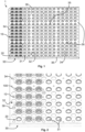
- Fig. 1 shows a first embodiment of an apparatus 1 according to the invention for thermal curing of a lens-forming material contained in a lens mold 10 (of which only a mold base part 100 is visible).
- Lens mold 10 is arranged on a mold support which is fixed to a tray 30.
- Tray 30 is made of metal, for example aluminum, or is made of any other suitable metal.
- the shape of the tray is generally rectangular, with the edges of the tray 30 being bent downwardly. At one corner (upper left corner in Fig. 1 ) the rectangular tray 30 has a cut-away portion. This cut-away portion forms a reference for identification of the rotational orientation of the tray 30 which may be helpful in the automated handling of tray 30.
- a number of supporting webs are arranged at the underside of tray 30, some of them being arranged to run in the horizontal direction (one of them being indicated in Fig. 1 by reference sign 35) while others being arranged to run perpendicular thereto. These supporting webs serve for increasing rigidity and stiffness of tray 30 and are secured to tray 30 with the aid of screws (not shown) screwed through small holes 36 provided in the tray 30.
- Tray 30 has an upper surface 32 and comprises a plurality of fixation openings embodied as disk-shaped mounting holes 31 at which mold supports are fixed to the tray 30.
- tray 30 comprises a plurality of disk-shaped passage holes 34 which are arranged offset relative to the disk-shaped mounting holes 31 at which the mold supports are fixed to the tray 30.
- the mold supports are embodied as rings 20 which are manufactured as separate pieces made of plastic, for example a polyolefine such as polypropylene.
- Ring 20 (the mold support) is shown in more detail.
- Ring 20 comprises an annular ring body 21 as well as a plurality of downwardly extending flexible latches 25.
- Annular ring body 21 has a bottom surface 22 and an annular top surface 23, and defines a central hole 24 surrounded by the annular ring body 21.
- Annular ring body 21 has a height H extending from the bottom surface 22 to the annular top surface 23.
- Annular top surface 23 has a top surface inner diameter DI and a top surface outer diameter DO.
- a conical surface 27 of the annular ring body 21 merges with the annular top surface 23 at an outer edge 28 of the annular top surface 23. Accordingly, conical surface 27 at its upper end has an outer diameter corresponding to the outer diameter DO of the annular top surface 23, while at its lower end it has a larger diameter DR corresponding to the outer diameter of the annular ring body 21.
- latches 25 are introduced from above into the disk-shaped mounting holes 31 of tray 30, whereupon ring 20 is lowered until the bottom surface 22 of annular ring body 21 abuts against the upper surface 32 of tray 30. Latches 25 then form a snap-fit with the tray 30, thus fixing ring 20 to the tray 30 at the disk-shaped mounting hole 31.
- ring 20 projects upwardly from the upper surface 32 of tray 30 by the height H of the annular ring body 21.
- This state where the ring 20 is mounted to the tray 30 at the disk-shaped mounting hole 31 is shown in Fig. 1, Fig. 2 and Fig. 3 at those locations where only the ring 20 is shown mounted to the tray 30.
- lens mold 10 comprises the mold base part 100 and the mold top part 101 mated to the mold base part 100 to form the mold cavity 102 defining the shape of the contact lens to be formed.
- a lens-forming material is dispensed into the concave lens-forming portion of mold base part 100.
- excess lens-forming material is displaced into an annular overflow channel 103 and the mold cavity 102 is sealed.
- Lens mold 10 further comprises a base surface 12 arranged on mold base part 100, and an annular abutment surface 11 arranged on an underside of mold base part 100.
- Annular abutment surface 11 is arranged at a predetermined distance D above the base surface 12 and has an abutment surface inner diameter Al and an abutment surface outer diameter AO.
- a centering flange 13 is arranged on the mold base part 100 and extends downwardly from the annular abutment surface 11 to the base surface 12.
- Mold base part 100 is provided with a tab 14 and mold top part 101 is provided with a tab 15, too. These tabs 14, 15 facilitate handling of the mold parts 100, 101. As can be seen best in Fig. 2 and Fig.
- the distance between adjacent mounting holes 31 of the tray 30 is chosen such that the tabs 14 of the mold base parts 100 of the lens molds 10 arranged on adjacent rings 20 cannot collide. This holds similarly for the tabs 15 of the mold top parts 101 of the lens molds 10 arranged on adjacent rings 20.
- annular abutment surface 11 on the underside of mold base part 100 of lens mold 10 rests on annular top surface 23 of the annular ring body 21 of ring 20 in a manner such that the base surface 12 is arranged at a clearance distance C above the upper surface 32 of tray 30.
- this clearance distance C may be in the range of 0.5 mm to 5 mm, and is the difference between the height H of the annular ring body 21 of the ring 20 and the predetermined distance D which the annular abutment surface 11 is arranged above the base surface 12. Accordingly, the arrangement of the lens mold 10 at the clearance distance C above the upper surface 32 of the tray 30 can be achieved by a suitable choice of the height H of the annular ring body 21 of the ring 20 and the predetermined distance D between the base surface 12 and the abutment surface 11 of the mold base part 100 of lens mold 10.
- the abutment surface inner diameter AI of the abutment surface 11 of lens mold 10 is smaller than the top surface inner diameter DI of the top surface 23 of the annular ring body 21.
- the abutment surface outer diameter AO of the abutment surface 11 of lens mold 10 is larger than the top surface outer diameter DO of the top surface 23 of annular ring body 21. This allows for a proper arrangement of the lens mold 10 on the ring 20.
- an inner diameter FI of the centering flange 13 is larger than the diameter DR of the lower end of the conical surface 27 which corresponds to the outer diameter of the annular ring body 21 in the embodiment shown.
- the central hole 24 defined by the annular ring body 21 is aligned with the mounting hole 31 of the tray 30.
- tray 30 is provided having a number of, for example, two hundred and fifty-six mounting holes 31.
- a corresponding number of rings 20 are fixed to the tray 30 at the mounting holes 31 with the aid of the latches 25.
- a lens mold 10 containing lens-forming material is placed, and in case of small misalignments during placement of the lens molds 10 on the rings 20 the centering flange 13 may come into contact with the conical surface 27 of the annular ring body 21 of ring 20.
- the lens mold 10 is thus guided onto the ring 20 and is properly aligned with the respective ring 20.
- the tray 30 is ready for being placed in an oven for thermal curing of the lens-forming material.
- the apparatus according to the invention may comprise a stack of trays comprising between twenty and thirty individual trays 30.
- the individual trays 30 of the stack are arranged spaced apart from each other with the aid of spacers 38 which are mounted to the respective tray 30 and which allow for easy stacking of the individual trays 30.
- Any suitable spacers known in the art can be used for this purpose and, accordingly, the spacers 38 are not described in more detail.
- Fig. 7 shows a second embodiment of the apparatus 2 according to the invention. Some aspects discussed in connection with the first embodiment also hold for the second embodiment, so that these aspects are not discussed here again.
- a tray 40 comprises a frame 400 and a number of supporting webs (not shown) on which metal sheets 401 (see Fig. 8 ) are arranged, which are supported by the frame 400 and by the webs (not shown), and which are retained thereon with the aid of screws 402 and washers 403.
- Frame 400, the supporting webs (not shown) as well as the metal sheets 401 may be made from aluminum to provide for sufficient rigidity and stiffness while at the same time being of light weight.
- an upper surface 42 of the tray 40 is formed that extends in a common plane.
- Tray 40 comprises a plurality of fixation openings embodied as disk-shaped mounting holes 41 (formed in the metal sheets 401) for fixing the mold support to the tray 40 at the mounting holes 41.
- tray 40 comprises a number of disk-shaped passage holes 44 (also formed in the metal sheets 401) which - in the embodiment shown - are larger in diameter than the mounting holes 41.
- two hundred and fifty-six disk-shaped passage holes 44 may be provided in the tray 40.
- Plastic plate 50 has a plate base surface 51 and a plate top surface 52, as can be seen best in Fig. 8 .
- the plate base surface 51 rests on the upper surface 42 of the tray 40 and has a plate thickness T.
- Plate 50 further comprises a plurality of first disk-shaped passage holes 54 and a plurality of second disk-shaped passage holes 58. At the walls of some of the second disk-shaped passage holes 58, latches 53 extend downwardly from the plastic plate 50.
- the latches 53 of plate 50 are introduced into the mounting holes 41 of tray 40, whereupon plate 50 is further moved downwards towards tray 40 until the plate base surface 51 comes to rest on the upper surface 42 of tray 40.
- the latches 53 engage the tray 40 at the mounting holes 41 through a snap-fit connection, thus removably fixing the plate 50 to the tray 40.
- This state is shown in Fig. 8 , and it can also be seen there that the first disk-shaped passage holes 54 of plate 50 are aligned with the passage holes 44 of tray 40 while the second disk-shaped passage holes 58 of plate 50 are aligned with the mounting holes 41 of tray 40.
- centering pins 55 are arranged on the plate top surface 52 around each of the first disk-shaped passage holes 54.
- the centering pins 55 project upwardly from the plate top surface 52 and may have a conical surface 56.
- two pairs of positioning pins 57 are arranged on the plate top surface 52 at different first and second angular positions, these angular positions being different by 90° (ninety degrees).
- the positioning pins 57 may also have a conical surface.
- the lens mold 60 again comprises a mold base part 600 and a mold top part 601 which are mated and enclose a mold cavity 602 containing a lens-forming material to be cured to form a contact lens.
- Mold base part 600 comprises a centering flange 64 projecting radially outwardly and forming the outer boundary of mold base part 600.
- a base surface 61 of mold base part 600 rests on the plate top surface 52, so that plate top surface 52 of plate 50 forms the support surface of the mold support and base surface 61 of mold base part 600 forms the bearing surface of the mold 60.
- the plate thickness T thus represents the clearance distance C by which the lens mold 60 is arranged spaced apart from the tray 40.
- Mold base part 600 further comprises an elongated tab 65 which helps in placing the lens mold 60 in a well-defined rotational orientation on plate 50, as is discussed in more detail below.
- mold base part 600 Upon placing lens mold 60 on the plate top surface 52, mold base part 600 must have a rotational orientation such that the elongated tab 65 fits between one of the two pairs of positioning pins 57, so that the positioning pins 57 determine the first and second angular positions of the elongated tab 65.
- the mold base part 600 must be placed on the plate top surface 52 such that the centering flange 64 is enclosed by the centering pins 55.
- the conical surfaces 56 of the centering pins 55 assist in centering the mold base part 600 (and thus in centering the mold 60) so that it comes to rest at the desired predetermined position.
- the elongated tab 65 may be guided by the conical surfaces of the positioning pins 57.
- tray 40 is ready for being placed in the oven for curing of the lens-forming material contained in the mold cavities 602 of the lens molds 60 to form the contact lenses.
- the apparatus according to the invention may comprise a stack of trays comprising between twenty and thirty individual trays 40.
- the individual trays 40 of the stack are arranged spaced apart from each other with the aid of spacers 43 (see Fig. 7 or Fig. 9 ), which are mounted to the respective tray 40 and which allow for easy stacking of the individual trays 40.
- spacers 43 Any suitable spacers known in the art can be used for this purpose and, accordingly, the spacers 43 are not described in more detail.
Landscapes
- Engineering & Computer Science (AREA)
- Mechanical Engineering (AREA)
- Health & Medical Sciences (AREA)
- Manufacturing & Machinery (AREA)
- Ophthalmology & Optometry (AREA)
- Moulds For Moulding Plastics Or The Like (AREA)
- Eyeglasses (AREA)
- Packaging Frangible Articles (AREA)
Description
- The invention relates to an apparatus for the thermal curing of a lens-forming material contained in a lens mold to form a contact lens, such as a soft contact lens.
- Production of ophthalmic lenses, in particular contact lenses such as soft contact lenses, is typically performed with the aid of molds comprising two mold halves, a male mold half and a female mold half. A lens-forming material is introduced into one of the two mold halves, for example into the female mold half, and the mold halves are then mated. The lens-forming material is thereafter cured to form the contact lens, which is subsequently demolded for further handling the contact lens.
-
US 2015/0147425 A1 discloses a method of producing contact lenses with the aid of a lens mold carrier to which mold units comprising re-usable mold halves typically made of glass are mounted. Such re-usable glass mold halves are expensive and are not suitable for thermal curing of the lens-forming material. - Another way to efficiently produce contact lenses is to use inexpensive mold halves. Inexpensive mold halves may be produced through injection-molding. Materials which are particularly suitable for injection-molding are injection-moldable plastics, such as polyolefines, for example polypropylene. However, polypropylene mold halves may deform as the lens-forming material shrinks during curing, so that the mold halves cannot be reused. Also, during curing of the lens-forming material no excess lens-forming material is allowed to flow into the mold cavity. Therefore, the extent of shrinkage of the lens-forming material must be kept small in order to produce contact lenses having the desired geometry and optical power. This is why curing of the lens-forming material in the mold cavity must occur only gradually, which is achieved by exposing the mold (the mated mold halves) and the lens-forming material contained therein to heat of a predetermined temperature and over an extended period of time, for example as much as one hour or even more. To nevertheless ensure that production of contact lenses with the aid of inexpensive single-use mold halves is efficient, it is mandatory that a very high number of mated mold halves containing the lens-forming material are simultaneously exposed to heat.
- It is therefore an object of the invention to suggest an apparatus allowing for simultaneous exposure of very high numbers of inexpensive single-use molds containing the lens-forming material to heat while at the same providing for a constant high quality of the contact lenses produced and while allowing for an automated handling of the molds.
- These and other objects of the invention are achieved with an apparatus as specified by the features of the independent claim. Advantageous aspects of the apparatus according to the invention are the subject of the dependent claims.
- As used in the specification including the appended claims, the singular forms "a", "an", and "the" include the plural, unless the context explicitly dictates otherwise. Also, whenever features are combined with the term "or", the term "or" is to be understood to also include "and" unless it is evident from the specification that the term "or" must be understood as being exclusive.
- In the present specification, the terms "upper/above" and "lower/below" are defined in relation to a tray on which a mold support and a lens mold are arranged.
- "Upper/above" describes a direction away from the tray towards the mold support and the lens mold, and "lower/below" describes a direction from the mold support and the lens mold towards the tray.
- Generally, different aspects can be combined with each other in any possible manner unless the specification dictates otherwise.
- In accordance with the invention, an apparatus for thermal curing of a lens-forming material contained in a lens mold to form an ophthalmic lens, in particular a contact lens, such as a soft contact lens is suggested.
- The apparatus comprises:
- a tray made of metal, for example aluminum, the tray having a fixation opening,
- a mold support made of plastic, for example a polyolefine such as polypropylene,
- wherein the mold support has a fastener fixed to the tray at the fixation opening and fixing the mold support to the tray,
- wherein the mold support further has a positioning guide configured to guide a lens mold onto the mold support and into a predetermined position relative to the tray, and wherein the mold support further has a support surface,
- a lens mold made from an injection-moldable plastic material, for example a polyolefine such as polypropylene, arranged on the mold support, the lens mold having a bearing surface resting on the support surface of the mold support.
- The lens mold is arranged spaced apart from the tray by a clearance distance.
- In accordance with one aspect of the apparatus according to the invention, the mold support is a separate piece and the fastener is a resilient latch removably fixing the mold support to the tray at the fixation opening.
- In accordance with a further aspect of the apparatus according to the invention, the mold support is a ring comprising an annular ring body and the latch. The latch extends from the annular ring body into the fixation opening of the tray and fixedly engages the tray.
- In accordance with still a further aspect of the apparatus according to the invention, the annular ring body has a height and a bottom surface resting on an upper surface of the tray. The lens mold has a base surface facing the tray. The bearing surface of the lens mold is arranged at a predetermined distance above the base surface. The height of the annular ring body is greater than the predetermined distance by the clearance distance.
- Yet in accordance with a further aspect of the apparatus according to the invention, the support surface is an annular top surface of the annular ring body. The annular top surface has a top surface inner diameter and a top surface outer diameter. The bearing surface of the lens mold is an annular abutment surface arranged on an underside of the lens mold. The annular abutment surface has an abutment surface inner diameter and an abutment surface outer diameter. The abutment surface inner diameter of the lens mold is smaller than the top surface inner diameter of the annular ring body and the abutment surface outer diameter of the lens mold is larger than the top surface outer diameter of the annular ring body.
- In accordance with a further aspect of the apparatus according to the invention, the positioning guide comprises a conical surface arranged at an outer peripheral portion of the annular ring body. The conical surface tapers inwardly with increasing distance from the tray. The lens mold further comprises a centering flange for engaging the conical surface of the annular ring body in order to align the annular abutment surface of the lens mold with the annular top surface of the annular ring body during arrangement of the lens mold on the ring.
- In accordance with still a further aspect of the apparatus according to the invention, the upper end of the conical surface merges with the annular top surface at an outer edge thereof having the top surface outer diameter. The lower end of the conical surface has a lower end conical surface diameter larger than the top surface outer diameter. The centering flange of the lens mold has a flange inner diameter which is larger than the lower end conical surface diameter.
- In accordance with yet another aspect of the apparatus according to the invention, the fixation opening of the tray is a disk-shaped mounting hole. The annular ring body defines a central hole surrounded by the annular ring body. The central hole of the annular ring body is aligned with the disk-shaped mounting hole of the tray.
- In accordance with another aspect of the apparatus according to the invention, the mold support comprises a plate having a plate base surface resting on an upper surface of the tray, and the latch. The latch extends from the plate into the fixation opening of the tray and fixedly engages the tray.
- According to a further aspect of the apparatus according to the invention, the plate has a plate thickness and comprises a plate top surface which is arranged opposite to the plate base surface. The plate top surface forms the support surface of the mold support. The bearing surface of the lens mold is a base surface of the lens mold that rests on the plate top surface. The plate thickness thus represents the clearance distance.
- According to still a further aspect of the apparatus according to the invention, the lens mold comprises a mold base part and a mold top part. The assembled mold base part and mold top part together form the lens mold. The mold base part comprises a centering flange projecting radially outwardly and forming the outer boundary of the mold base part. The positioning guide comprises at least three centering pins arranged on the plate top surface at different locations such that they enclose the centering flange of the mold base part, thereby defining the predetermined position of the lens mold relative to the tray.
- Yet in accordance with a further aspect of the apparatus according to the invention, the mold base part further comprises a tab extending radially outwardly from the centering flange. The positioning guide further comprises at least one pair of positioning pins arranged at predetermined positions on the plate top surface to determine the angular position of the tab of the mold base part.
- In accordance with a further aspect of the apparatus according to the invention, the at least one pair of positioning pins comprises two pairs of positioning pins arranged at different predetermined positions on the plate top surface to determine a first angular position and a second angular position of the tab of the mold base part. The second angular position is angularly displaced relative to the first angular position by an angle of 90°.
- In accordance with a further aspect of the apparatus according to the invention, the fixation opening of the tray is a disk-shaped mounting hole and the tray further comprises an additional disk-shaped passage hole. The plate comprises first and second disk-shaped passage holes, with the first passage hole of the plate being aligned with the passage hole of the tray and the second passage hole of the plate being aligned with the mounting hole of the tray.
- In accordance with a further aspect of the apparatus according to the invention, the tray comprises a passage hole and the plate comprises a through-hole. The through-hole of the plate is arranged superimposed with the passage hole of the tray.
- In accordance with another aspect of the apparatus according to the invention, the apparatus comprises a plurality of plates adjacently arranged on the same tray.
- In accordance with a further, more general, aspect of the apparatus according to the invention, the apparatus comprises a stack of trays with mold supports fixed to the respective trays and with lens molds arranged on the mold supports. The trays are arranged one above the other in the stack and are separated by spacers.
- The metal tray of the apparatus according to the invention provides for the necessary rigidity and stiffness, as the tray may have a considerable size allowing a high number of molds to be arranged on the same tray. For example, a number of two hundred and fifty-six molds (arranged in sixteen rows and sixteen columns) or even more may be arranged on a single tray. Aluminum may be used as a metal, since aluminum is of comparatively light weight and does not have a high heat capacity, so that it allows for a comparatively quick heating when the tray with the molds arranged on the mold supports are heated in the oven and also allows for a quick cooling when the temperature is cooled down again in the oven (so that the plates can be quickly handled after removal from the oven). The mold support is made of a plastic which acts as a thermal insulator. Polyolefines, for example polypropylene, are plastic materials having the afore-mentioned properties and at the same time allow for a cheap and reliable manufacturing of the mold supports, for example by injection molding. As the mold is arranged on the mold support spaced apart from the metal tray by the clearance distance the lens mold is practically arranged thermally separated from the tray as there is no heat conductive contact between the les mold and the tray. Accordingly, when the molds are exposed to heat during curing of the lens-forming material over extended periods of time, for example in an oven, the entire mold containing the lens-forming material is uniformly heated through convection. Any non-uniform heating of the mold through a thermally conductive contact of the mold with the metal plate is avoided. This leads to a uniform and homogeneous curing of the lens-forming material contained in the mold. The fastener allows for a precise and easy mounting of the mold support to the tray.
- The plastic mold support can be made as a separate piece which can be easily fixed to the tray at the fixation opening of the tray, for example by means of a resilient latch of the mold support, thus enabling an easy and quick mounting or removal of the mold support to the tray (for example in case the mold supports must be mounted to the tray or must be removed from the tray, for example during replacement).
- One advantageous design option for the plastic mold support is a ring comprising an annular ring body from which the latch extends. The ring design allows for an easy, reliable and cheap production of the mold supports (e.g. through injection molding) and allows for an easy mounting of the individual mold supports to the metal tray at the fixation openings by simply having the one or more latches of the ring form a snap-fit connection with the walls of the tray at the respective fixation openings. The snap-fit connection can be formed through insertion of the ring into the fixation opening of the metal tray from above. Also, the snap-fit connection allows for an easy removal of the rings from the tray, if necessary, for example during replacement.
- Preferably, the lens mold has a base surface facing the tray, and this base surface is arranged above the upper surface of the tray and spaced apart from the upper surface of the tray by the clearance distance. This arrangement of the base surface of the lens mold above the upper surface of the tray can be achieved by the plastic mold support having an annular ring body of a predetermined height, and this predetermined height of the annular ring body is greater than the distance at which the bearing surface of the lens mold is arranged above the base surface of the lens mold by the said clearance distance.
- As has been discussed already, the lens mold may have an abutment surface resting on an annular top surface of the annular ring body. As the molds are placed on the ring-shaped mold supports (for example with the aid of a robot), they may not be absolutely precisely aligned with the ring body. To allow for small positional misalignments, the abutment surface inner diameter of the lens mold is smaller than the top surface inner diameter of the annular ring body, and the abutment surface outer diameter of the lens mold is larger than the top surface outer diameter of the annular ring body. As a result, even in case of small misalignments the molds can be properly placed on the ring-shaped mold support, so that the bearing surface of the lens mold rests on the annular top surface of the mold support.
- Placement of the lens mold on the ring-shaped mold support may be further facilitated in case the ring-shaped mold support comprises a conical centering surface at an outer peripheral portion of the annular ring body of the ring-shaped mold support. In particular, this conical surface merges with the annular top surface on which the bearing surface of the lens mold rests. The lens mold comprises a centering flange extending downwardly in a direction towards the tray. During placement of the lens mold on the mold support, in case of a small positional misalignment the centering flange of the mold may engage the conical surface of the ring-shaped mold support and thus assists in guiding the lens mold to be aligned with the mold support, so that the lens mold comes to properly rest on the mold support.
- The annular ring body of the ring-shaped mold support defines a central hole. In case the fixation opening is a disk-shaped mounting hole and the central hole of the annular ring body is aligned with the mounting hole of the tray, convection is further improved. This is advantageous with respect to a homogeneous curing of the lens-forming material contained in the lens mold.
- In another advantageous design option the plastic mold support comprises a plate having a plate base surface resting on the upper surface of the tray. The latch extends from the plate into the fixation opening of the tray thus fixing the (plastic) plate to the tray. The plate design also renders production of the mold support easy and inexpensive due to the simple shape of the plate. For example, the plate may also be produced through injection molding and can be easily attached or removed from the tray, which is advantageous when the plate has to be mounted to the tray or has to be removed (e.g. for replacement). The molds may be directly arranged on the upper surface of the plastic plate so that the plate thickness represents the clearance distance C by which the molds are arranged spaced from the tray.
- Lens molds typically comprise a mold base part and a mold top part. The mold base part of the lens mold may comprise a centering flange that projects radially outwardly and runs circumferentially around the mold base part, thus forming the outer boundary of the mold base part. For properly centering the mold on the plate-shaped mold support at the desired position three or more centering pins may be arranged at different locations on the top surface of the plate such that they enclose the centering flange. While more than three such centering pins may be arranged on the plate top surface, at least three must be there to achieve the centering function. The centering pins may comprise conical surfaces to facilitate centering of the molds at the desired position in case of small misalignments during placement of the mold on the plastic plate.
- In addition, in order to provide for a proper orientation of the mold on the plastic plate, the mold base part may comprise a tab and the plate may comprise at least one pair of positioning pins. The mold is then arranged on the plastic plate such that the tab of the mold base part extends between the two positioning pins of the pair. Thus, the (angular) orientation of the mold is determined, which may be of particular advantage as a high number of molds is to be arranged on the tray or the plastic plate, respectively, so that collisions or overlapping of mold portions of adjacently arranged molds can be avoided.
- For example, it may be possible to have two pairs of positioning pins which are arranged at different predetermined angular positions which are angularly displaced by ninety degrees. This allows for arrangement of the molds in exactly two positions, and also allows for arranging a high number of molds on the plate for simultaneous curing of the lens-forming material contained in the molds, thus rendering lens production particularly effective.
- The fixation opening of the tray may be embodied as one or more disk-shaped mounting holes, and the tray may further comprise one or more additional disk-shaped passage holes. Correspondingly, the plate may comprises first and second disk-shaped passage holes, with the first passage hole(s) of the plate being aligned with the passage hole(s) of the tray and the second passage hole(s) of the plate being aligned with the mounting hole(s) of the tray in order to improve the flow of heated air and the homogeneous curing of the lens-forming material.
- Regardless of the design of the mold support, it is particularly advantageous to have a stack of trays with mold supports fixed to the respective trays and lens molds arranged on the mold supports, with the trays being stacked one above the other in the stack and being separated by spacers. This further improves the efficiency of the production process, since such stack of trays further increases the number of lens molds which can be simultaneously exposed to heat, thus increasing the number of lenses which can be simultaneously produced.
- Further advantageous aspects of the invention become apparent from the following description of embodiments of the invention with the aid of the drawings in which:
- Fig. 1
- shows a perspective view of a first embodiment of the apparatus according to the invention;
- Fig. 2
- is an enlarged view of a portion (lower left corner portion) of the apparatus shown in
Fig. 1 ; - Fig. 3
- shows a cross-sectional view of the apparatus according to the first embodiment;
- Fig. 4
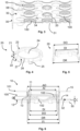
- shows perspective view of the mold support (ring) according to the first embodiment of the apparatus according to the invention;
- Fig. 5
- is a cross-sectional view of the mold support (ring) shown in
Fig. 4 ; - Fig. 6
- is a detailed cross-sectional view of the lens mold arranged on the mold support (ring);
- Fig. 7
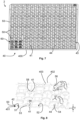
- shows a perspective view of a second embodiment of the apparatus according to the invention;
- Fig. 8
- shows an enlarged cross-sectional view of a portion of the apparatus shown in
Fig. 7 ; - Fig. 9
- shows an enlarged view of a portion of the apparatus shown in
Fig. 7 (lower left corner portion); and - Fig. 10
- shows a cross-sectional view of a portion of the apparatus shown in
Fig. 7 . -
Fig. 1 shows a first embodiment of anapparatus 1 according to the invention for thermal curing of a lens-forming material contained in a lens mold 10 (of which only amold base part 100 is visible).Lens mold 10 is arranged on a mold support which is fixed to atray 30.Tray 30 is made of metal, for example aluminum, or is made of any other suitable metal. The shape of the tray is generally rectangular, with the edges of thetray 30 being bent downwardly. At one corner (upper left corner inFig. 1 ) therectangular tray 30 has a cut-away portion. This cut-away portion forms a reference for identification of the rotational orientation of thetray 30 which may be helpful in the automated handling oftray 30. A number of supporting webs are arranged at the underside oftray 30, some of them being arranged to run in the horizontal direction (one of them being indicated inFig. 1 by reference sign 35) while others being arranged to run perpendicular thereto. These supporting webs serve for increasing rigidity and stiffness oftray 30 and are secured totray 30 with the aid of screws (not shown) screwed throughsmall holes 36 provided in thetray 30. -
Tray 30 has anupper surface 32 and comprises a plurality of fixation openings embodied as disk-shaped mounting holes 31 at which mold supports are fixed to thetray 30. In addition,tray 30 comprises a plurality of disk-shaped passage holes 34 which are arranged offset relative to the disk-shaped mounting holes 31 at which the mold supports are fixed to thetray 30. The mold supports are embodied asrings 20 which are manufactured as separate pieces made of plastic, for example a polyolefine such as polypropylene. InFig. 1 as well as inFig. 2 andFig. 3 , at some of the disk-shaped mounting holes 31 only therings 20 are shown fixed to the tray 30 (with nolens molds 10 being arranged on the rings 20) while at other disk-shaped mounting holes 31 amold base part 100 oflens mold 10 is shown arranged on the respective rings 20. This is shown only for the sake of better understanding, since in practice only assembledcomplete lens molds 10 comprising both themold base part 100 as well as a moldtop part 101 and containing lens-forming material enclosed in amold cavity 102 are arranged on therings 20 in the manner shown inFig.6 , as will be described in more detail below. - In
Fig. 4 and Fig. 5 ring 20 (the mold support) is shown in more detail.Ring 20 comprises anannular ring body 21 as well as a plurality of downwardly extendingflexible latches 25.Annular ring body 21 has abottom surface 22 and an annulartop surface 23, and defines acentral hole 24 surrounded by theannular ring body 21.Annular ring body 21 has a height H extending from thebottom surface 22 to the annulartop surface 23. - Annular
top surface 23 has a top surface inner diameter DI and a top surface outer diameter DO. Aconical surface 27 of theannular ring body 21 merges with the annulartop surface 23 at anouter edge 28 of the annulartop surface 23. Accordingly,conical surface 27 at its upper end has an outer diameter corresponding to the outer diameter DO of the annulartop surface 23, while at its lower end it has a larger diameter DR corresponding to the outer diameter of theannular ring body 21. - To mount
ring 20 totray 30, latches 25 are introduced from above into the disk-shaped mounting holes 31 oftray 30, whereuponring 20 is lowered until thebottom surface 22 ofannular ring body 21 abuts against theupper surface 32 oftray 30.Latches 25 then form a snap-fit with thetray 30, thus fixingring 20 to thetray 30 at the disk-shaped mountinghole 31. In this state, ring 20 projects upwardly from theupper surface 32 oftray 30 by the height H of theannular ring body 21. This state where thering 20 is mounted to thetray 30 at the disk-shaped mountinghole 31 is shown inFig. 1, Fig. 2 andFig. 3 at those locations where only thering 20 is shown mounted to thetray 30. - As can be seen from
Fig. 6 ,lens mold 10 comprises themold base part 100 and the moldtop part 101 mated to themold base part 100 to form themold cavity 102 defining the shape of the contact lens to be formed. Before assemblingmold base part 100 and moldtop part 101 oflens mold 10, a lens-forming material is dispensed into the concave lens-forming portion ofmold base part 100. Upon mating the moldtop part 101 with themold base part 100, excess lens-forming material is displaced into anannular overflow channel 103 and themold cavity 102 is sealed. -
Lens mold 10 further comprises abase surface 12 arranged onmold base part 100, and anannular abutment surface 11 arranged on an underside ofmold base part 100.Annular abutment surface 11 is arranged at a predetermined distance D above thebase surface 12 and has an abutment surface inner diameter Al and an abutment surface outer diameter AO. A centeringflange 13 is arranged on themold base part 100 and extends downwardly from theannular abutment surface 11 to thebase surface 12.Mold base part 100 is provided with atab 14 and moldtop part 101 is provided with atab 15, too. Thesetabs mold parts Fig. 2 andFig. 3 , the distance between adjacent mountingholes 31 of thetray 30 is chosen such that thetabs 14 of themold base parts 100 of thelens molds 10 arranged onadjacent rings 20 cannot collide. This holds similarly for thetabs 15 of the moldtop parts 101 of thelens molds 10 arranged onadjacent rings 20. - During placement of the
lens mold 10 on thering 20, in case of a small misalignment the centeringflange 13 may come into contact with theconical surface 27 which then guides thelens mold 10 and properly aligns thelens mold 10 with thering 20. Once thelens mold 10 is arranged on thering 20,annular abutment surface 11 on the underside ofmold base part 100 oflens mold 10 rests on annulartop surface 23 of theannular ring body 21 ofring 20 in a manner such that thebase surface 12 is arranged at a clearance distance C above theupper surface 32 oftray 30. For example, this clearance distance C may be in the range of 0.5 mm to 5 mm, and is the difference between the height H of theannular ring body 21 of thering 20 and the predetermined distance D which theannular abutment surface 11 is arranged above thebase surface 12. Accordingly, the arrangement of thelens mold 10 at the clearance distance C above theupper surface 32 of thetray 30 can be achieved by a suitable choice of the height H of theannular ring body 21 of thering 20 and the predetermined distance D between thebase surface 12 and theabutment surface 11 of themold base part 100 oflens mold 10. - As can be seen further in
Fig. 6 , the abutment surface inner diameter AI of theabutment surface 11 oflens mold 10 is smaller than the top surface inner diameter DI of thetop surface 23 of theannular ring body 21. The abutment surface outer diameter AO of theabutment surface 11 oflens mold 10 is larger than the top surface outer diameter DO of thetop surface 23 ofannular ring body 21. This allows for a proper arrangement of thelens mold 10 on thering 20. Finally, an inner diameter FI of the centeringflange 13 is larger than the diameter DR of the lower end of theconical surface 27 which corresponds to the outer diameter of theannular ring body 21 in the embodiment shown. As can also be seen inFig. 6 , thecentral hole 24 defined by theannular ring body 21 is aligned with the mountinghole 31 of thetray 30. - Assembly of the
apparatus 1 according to the first embodiment is performed as follows. First,tray 30 is provided having a number of, for example, two hundred and fifty-six mounting holes 31. Next, a corresponding number ofrings 20 are fixed to thetray 30 at the mountingholes 31 with the aid of thelatches 25. Thereafter, on each of the rings 20 alens mold 10 containing lens-forming material is placed, and in case of small misalignments during placement of thelens molds 10 on therings 20 the centeringflange 13 may come into contact with theconical surface 27 of theannular ring body 21 ofring 20. Thelens mold 10 is thus guided onto thering 20 and is properly aligned with therespective ring 20. Once alens mold 10 is arranged on each of therings 20, thetray 30 is ready for being placed in an oven for thermal curing of the lens-forming material. - For increasing the efficiency, it is advantageous to arrange a plurality of
trays 30 withrings 20 mounted to the mountingholes 31 and withlens molds 10 arranged on therings 20 in a stack. For example, the apparatus according to the invention may comprise a stack of trays comprising between twenty and thirtyindividual trays 30. Theindividual trays 30 of the stack are arranged spaced apart from each other with the aid ofspacers 38 which are mounted to therespective tray 30 and which allow for easy stacking of theindividual trays 30. Any suitable spacers known in the art can be used for this purpose and, accordingly, thespacers 38 are not described in more detail. Once the stack of trays has been formed, it is placed in an oven for thermally curing the lens-forming material contained in thelens molds 10. -
Fig. 7 shows a second embodiment of theapparatus 2 according to the invention. Some aspects discussed in connection with the first embodiment also hold for the second embodiment, so that these aspects are not discussed here again. In the second embodiment atray 40 comprises aframe 400 and a number of supporting webs (not shown) on which metal sheets 401 (seeFig. 8 ) are arranged, which are supported by theframe 400 and by the webs (not shown), and which are retained thereon with the aid ofscrews 402 andwashers 403.Frame 400, the supporting webs (not shown) as well as themetal sheets 401 may be made from aluminum to provide for sufficient rigidity and stiffness while at the same time being of light weight. When themetal sheets 401 are arranged in place, anupper surface 42 of thetray 40 is formed that extends in a common plane. -
Tray 40 comprises a plurality of fixation openings embodied as disk-shaped mounting holes 41 (formed in the metal sheets 401) for fixing the mold support to thetray 40 at the mounting holes 41. In addition,tray 40 comprises a number of disk-shaped passage holes 44 (also formed in the metal sheets 401) which - in the embodiment shown - are larger in diameter than the mounting holes 41. By way of example, two hundred and fifty-six disk-shaped passage holes 44 may be provided in thetray 40. - Unlike the mold support of the first embodiment which is embodied as a ring, the mold support of the second embodiment of the apparatus according to the invention is embodied as a
plastic plate 50, and a plurality of suchplastic plates 50 may be adjacently arranged on the tray and are fixed to thesame tray 40. By way of example only and as can be seen inFig. 7 , sixteen suchplastic plates 50 may be adjacently arranged on thesame tray 40 and are fixed thereto. -
Plastic plate 50 has aplate base surface 51 and a platetop surface 52, as can be seen best inFig. 8 . Theplate base surface 51 rests on theupper surface 42 of thetray 40 and has a platethickness T. Plate 50 further comprises a plurality of first disk-shaped passage holes 54 and a plurality of second disk-shaped passage holes 58. At the walls of some of the second disk-shaped passage holes 58, latches 53 extend downwardly from theplastic plate 50. - To mount
plastic plate 50 tometal tray 40, thelatches 53 ofplate 50 are introduced into the mountingholes 41 oftray 40, whereuponplate 50 is further moved downwards towardstray 40 until theplate base surface 51 comes to rest on theupper surface 42 oftray 40. Thelatches 53 engage thetray 40 at the mountingholes 41 through a snap-fit connection, thus removably fixing theplate 50 to thetray 40. This state is shown inFig. 8 , and it can also be seen there that the first disk-shaped passage holes 54 ofplate 50 are aligned with the passage holes 44 oftray 40 while the second disk-shaped passage holes 58 ofplate 50 are aligned with the mountingholes 41 oftray 40. - As can be seen further from
Fig. 8 , four centeringpins 55 are arranged on the platetop surface 52 around each of the first disk-shaped passage holes 54. The centering pins 55 project upwardly from the platetop surface 52 and may have aconical surface 56. In addition, near each of the first disk-shaped passage holes 54 two pairs of positioning pins 57 are arranged on the platetop surface 52 at different first and second angular positions, these angular positions being different by 90° (ninety degrees). The positioning pins 57 may also have a conical surface. The function of the centering pins 55 and of the positioning pins 57 will be described in more detail below. - As can be seen best from
Fig. 9 and Fig. 10 , thelens mold 60 again comprises amold base part 600 and a moldtop part 601 which are mated and enclose amold cavity 602 containing a lens-forming material to be cured to form a contact lens.Mold base part 600 comprises a centeringflange 64 projecting radially outwardly and forming the outer boundary ofmold base part 600. Abase surface 61 ofmold base part 600 rests on the platetop surface 52, so that platetop surface 52 ofplate 50 forms the support surface of the mold support andbase surface 61 ofmold base part 600 forms the bearing surface of themold 60. The plate thickness T thus represents the clearance distance C by which thelens mold 60 is arranged spaced apart from thetray 40.Mold base part 600 further comprises anelongated tab 65 which helps in placing thelens mold 60 in a well-defined rotational orientation onplate 50, as is discussed in more detail below. - Upon placing
lens mold 60 on the platetop surface 52,mold base part 600 must have a rotational orientation such that theelongated tab 65 fits between one of the two pairs of positioning pins 57, so that the positioning pins 57 determine the first and second angular positions of theelongated tab 65. In addition, themold base part 600 must be placed on the platetop surface 52 such that the centeringflange 64 is enclosed by the centering pins 55. In case of a small misalignment, theconical surfaces 56 of the centering pins 55 assist in centering the mold base part 600 (and thus in centering the mold 60) so that it comes to rest at the desired predetermined position. Similarly, theelongated tab 65 may be guided by the conical surfaces of the positioning pins 57. - Once
lens molds 60 are placed at each of the desired predetermined positions on thetop surface 52 of each of theplates 50 fixed to the tray 40 (in the embodiment shown, once two hundred and fifty-sixlens molds 60 are placed on theplates 50 fixed to the tray 40),tray 40 is ready for being placed in the oven for curing of the lens-forming material contained in themold cavities 602 of thelens molds 60 to form the contact lenses. - For increasing the efficiency, it is advantageous to arrange a plurality of
trays 40 withplates 50 mounted to the mountingholes 41 and withlens molds 60 arranged on thetop surfaces 52 ofplates 50 in a stack. For example, the apparatus according to the invention may comprise a stack of trays comprising between twenty and thirtyindividual trays 40. Theindividual trays 40 of the stack are arranged spaced apart from each other with the aid of spacers 43 (seeFig. 7 orFig. 9 ), which are mounted to therespective tray 40 and which allow for easy stacking of theindividual trays 40. Any suitable spacers known in the art can be used for this purpose and, accordingly, thespacers 43 are not described in more detail. Once the stack of trays has been formed, it is placed in an oven for thermally curing the lens-forming material contained in thelens molds 60. - While embodiments of the invention have been described with the aid of the drawings, it is obvious that many changes and/or modifications are possible without departing from the teaching underlying the invention. Therefore, the scope of protection is not limited to the embodiments described but is defined by the appended claims.
Claims (16)
- Apparatus (1, 2) for the thermal curing of a lens-forming material contained in a lens mold (10, 60) to form a contact lens, such as a soft contact lens, the apparatus comprising:- a tray (30, 40) made of metal, for example aluminum, the tray having a fixation opening (31, 41),- a mold support (20, 50) made of plastic, for example a polyolefine such as polypropylene,wherein the mold support (20, 50) has a fastener (25, 53) fixed to the tray (30, 40) at the fixation opening (31, 41) and fixing the mold support (20, 50) to the tray (30, 40), wherein the mold support (20, 50) further has a positioning guide (27, 55) configured to guide a lens mold (10, 60) onto the mold support (20, 50) and into a predetermined position relative to the tray (30, 40)and wherein the mold support (20, 50) further has a support surface (23, 52), and- a lens mold (10, 60) made from an injection-moldable plastic material, for example a polyolefine such as polypropylene, arranged on the mold support (20, 50), the lens mold (10, 60) having a bearing surface (11, 61) resting on the support surface (23, 52) of the mold support (20, 50),wherein the lens mold (10, 60) is arranged spaced apart from the tray (30, 40) by a clearance distance (C, T).
- Apparatus (1, 2) according to claim 1, wherein the mold support (20, 50) is a separate piece, and wherein the fastener is a resilient latch (25, 53) removably fixing the mold support (20, 50) to the tray (30, 40) at the fixation opening (31, 41).
- Apparatus (1) according to claim 2, wherein the mold support is a ring (20) comprising an annular ring body (21) and the latch (25), the latch (25) extending from the annular ring body (21) into the fixation opening (31) of the tray (30) and fixedly engaging the tray (30).
- Apparatus (1) according to claim 3, wherein the annular ring body (21) has a height (H) and a bottom surface (22) resting on an upper surface (32) of the tray (30), wherein the lens mold (10) has a base surface (12) facing the tray (30), and wherein the bearing surface of the lens mold (10) is arranged at a predetermined distance (D) above the base surface (12), with the height (H) of the annular ring body (21) being greater than the predetermined distance (D) by the clearance distance (C).
- Apparatus (1) according to anyone of claims 3 or 4, wherein the support surface is an annular top surface (23) of the annular ring body (21), the annular top surface (23) having a top surface inner diameter (DI) and a top surface outer diameter (DO), and wherein the bearing surface of the lens mold (10) is an annular abutment surface (11) arranged on an underside of the lens mold (10), the annular abutment surface (11) having an abutment surface inner diameter (Al) and an abutment surface outer diameter (AO), with the abutment surface inner diameter (Al) of the lens mold (10) being smaller than the top surface inner diameter (DI) of the annular ring body (21) and the abutment surface outer diameter (AO) of the lens mold (10) being larger than the top surface outer diameter (DO) of the annular ring body (21).
- Apparatus (1) according to claim 5, wherein the positioning guide comprises a conical surface (27) arranged at an outer peripheral portion of the annular ring body (21), the conical surface (27) tapering inwardly with increasing distance from the tray (30), and wherein the lens mold (10) further comprises a centering flange (13) for engaging the conical surface (27) of the annular ring body (21) in order to align the annular abutment surface (11) of the lens mold (10) with the annular top surface (23) of the annular ring body (21) during arrangement of the lens mold (10) on the ring (20).
- Apparatus (1) according to claim 6, wherein the upper end of the conical surface (27) merges with the annular top surface (23) at an outer edge (28) thereof having the top surface outer diameter (DO), wherein the lower end of the conical surface (27) has a lower end conical surface diameter (DR) larger than the top surface outer diameter (DO), and wherein the centering flange (13) of the lens mold (10) has a flange inner diameter (FI) larger than the lower end conical surface diameter (DR).
- Apparatus (1) according to anyone of claims 3 to 7, wherein the fixation opening of the tray (30) is a disk-shaped mounting hole (31), and wherein the annular ring body (21) defines a central hole (24) surrounded by the annular ring body (21), the central hole (24) of the annular ring body (21) being aligned with the disk-shaped mounting hole (31) of the tray (30).
- Apparatus (2) according to claim 2, wherein the mold support comprises a plate (50) having a plate base surface (51) resting on an upper surface (42) of the tray (40) and the latch (53), the latch (53) extending from the plate (50) into the fixation opening (41) of the tray (40) and fixedly engaging the tray (40).
- Apparatus (2) according to claim 9, wherein the plate (50) has a plate thickness (T) and comprises a plate top surface (52) being arranged opposite to the plate base surface (51), wherein the plate top surface (52) forms the support surface of the mold support, and wherein the bearing surface of the lens mold (60) is a base surface (61) of the lens mold (60) resting on the plate top surface (52), the plate thickness (T) thus representing the clearance distance (C).
- Apparatus (2) according to claim 10, wherein the lens mold (60) comprises a mold base part (600) and a mold top part (601), the assembled mold base part (600) and mold top part (601) together forming the lens mold (60), wherein the mold base part (600) comprises a centering flange (64) projecting radially outwardly and forming the outer boundary of the mold base part (600), and wherein the positioning guide comprises at least three centering pins (55) arranged on the plate top surface (52) at different locations such that they enclose the centering flange (64) of the mold base part (600), thereby defining the predetermined position of the lens mold (60) relative to the tray (40).
- Apparatus (2) according to claim 11, wherein the mold base part (600) further comprises a tab (65) extending radially outwardly from the centering flange (64), and wherein the positioning guide further comprises at least one pair of positioning pins (57) arranged at predetermined positions on the plate top surface (52) to determine the angular position of the tab (65) of the mold base part (600).
- Apparatus (2) according to claim 12, wherein the at least one pair of positioning pins (57) comprises two pairs of positioning pins (57) arranged at different predetermined positions on the plate top surface (52) to determine a first angular position and a second angular position of the tab (65) of the mold base part (600), the second angular position being angularly displaced relative to the first angular position by an angle of 90°.
- Apparatus (2) according to anyone of claims 9 to 13, wherein the fixation opening of the tray (40) is a disk-shaped mounting hole (41) and the tray (40) further comprises an additional disk-shaped passage hole (44), and wherein the plate (50) comprises a first and second disk-shaped passage holes (54, 58), with the first passage hole (54) of the plate (50) being aligned with the passage hole (44) of the tray (40) and the second passage hole (58) of the plate (50) being aligned with the mounting hole (41) of the tray (40).
- Apparatus (2) according to any one of claims 9 to 14, wherein the apparatus comprises a plurality of plates (50) adjacently arranged on the same tray (40).
- Apparatus (1, 2) according to any one of claims 1 to 15, wherein the apparatus comprises a stack of trays (30, 40) with mold supports (20, 50) fixed to the respective trays (30, 40) and with lens molds (10, 60) arranged on the mold supports (20, 50), the trays (30, 40) being arranged one above the other in the stack and being separated by spacers (38, 43).
Applications Claiming Priority (2)
| Application Number | Priority Date | Filing Date | Title |
|---|---|---|---|
| US201762477039P | 2017-03-27 | 2017-03-27 | |
| PCT/IB2018/051955 WO2018178823A1 (en) | 2017-03-27 | 2018-03-22 | Apparatus for the thermal curing of a lens-forming material |
Publications (2)
| Publication Number | Publication Date |
|---|---|
| EP3600860A1 EP3600860A1 (en) | 2020-02-05 |
| EP3600860B1 true EP3600860B1 (en) | 2024-12-11 |
Family
ID=61913497
Family Applications (1)
| Application Number | Title | Priority Date | Filing Date |
|---|---|---|---|
| EP18716672.3A Active EP3600860B1 (en) | 2017-03-27 | 2018-03-22 | Apparatus for the thermal curing of a lens-forming material |
Country Status (7)
| Country | Link |
|---|---|
| US (1) | US20180272632A1 (en) |
| EP (1) | EP3600860B1 (en) |
| CN (1) | CN110312615B (en) |
| HU (1) | HUE069878T2 (en) |
| MY (1) | MY205458A (en) |
| SG (2) | SG10202110320VA (en) |
| WO (1) | WO2018178823A1 (en) |
Families Citing this family (7)
| Publication number | Priority date | Publication date | Assignee | Title |
|---|---|---|---|---|
| WO2021240438A1 (en) * | 2020-05-29 | 2021-12-02 | Alcon Inc. | Carrier for carrying an ophthalmic lens during its treatment in a bath |
| EP4667202A1 (en) | 2021-09-14 | 2025-12-24 | Alcon Inc. | Production line for the production of ophthalmic lenses |
| TW202327851A (en) | 2021-09-14 | 2023-07-16 | 瑞士商愛爾康公司 | Production line for the production of ophthalmic lenses |
| EP4401965B1 (en) | 2021-09-14 | 2025-09-03 | Alcon Inc. | Production line for the production of ophthalmic lenses |
| KR20240036666A (en) | 2021-09-14 | 2024-03-20 | 알콘 인코포레이티드 | Production line for ophthalmic lens production |
| US12330384B2 (en) | 2021-09-14 | 2025-06-17 | Alcon Inc. | Production line for the production of ophthalmic lenses |
| US20250334480A1 (en) * | 2021-10-27 | 2025-10-30 | Transitions Optical, Ltd. | Optical Article Inspection Apparatus and Method |
Family Cites Families (13)
| Publication number | Priority date | Publication date | Assignee | Title |
|---|---|---|---|---|
| JPH04505219A (en) * | 1988-11-09 | 1992-09-10 | ブライト、エルビン・メリル | Optical plastic and its manufacturing method |
| US6558584B1 (en) * | 2000-03-31 | 2003-05-06 | Bausch & Lomb Incorporated | Apparatus and method for handling an ophthalmic lens |
| US6439870B1 (en) * | 2000-05-26 | 2002-08-27 | Johnson & Johnson Vision Care, Inc. | Apparatus for automated ophthalmic lens fabrication |
| ATE330778T1 (en) * | 2001-03-27 | 2006-07-15 | Novartis Ag | MOLD ARRANGEMENT FOR PRODUCING SEVERAL CONTACT LENSES |
| GB2409427A (en) * | 2003-12-23 | 2005-06-29 | Bausch & Lomb | Handling moulded opthalmic lenses |
| ES2273161T3 (en) * | 2004-07-02 | 2007-05-01 | Interglass Technology Ag | DEVICE FOR ALIGNING TWO CASCARA MOLDS. |
| KR100590230B1 (en) * | 2005-11-23 | 2006-06-19 | 대명광학 주식회사 | Mold transport tray |
| MY147130A (en) * | 2007-05-18 | 2012-10-31 | Coopervision Int Holding Co Lp | Thermal curing methods and systems for forming contact lenses |
| CN102387910B (en) * | 2009-04-09 | 2015-09-30 | 诺华股份有限公司 | For automatically manufacturing the method and apparatus of different double-curved surface optical lens |
| WO2013016124A1 (en) * | 2011-07-28 | 2013-01-31 | Coopervision International Holding Company, Lp | Methods and systems for manufacturing contact lenses |
| CN202807869U (en) * | 2012-08-30 | 2013-03-20 | 骏曦股份有限公司 | Transfer device for contact lens inspection |
| HUE054580T2 (en) * | 2013-11-27 | 2021-09-28 | Alcon Inc | Lens mold carrier |
| GB2537147B (en) * | 2015-04-09 | 2021-03-31 | Coopervision Int Ltd | A tray for use in manufacturing contact lenses |
-
2018
- 2018-03-22 WO PCT/IB2018/051955 patent/WO2018178823A1/en not_active Ceased
- 2018-03-22 SG SG10202110320V patent/SG10202110320VA/en unknown
- 2018-03-22 EP EP18716672.3A patent/EP3600860B1/en active Active
- 2018-03-22 HU HUE18716672A patent/HUE069878T2/en unknown
- 2018-03-22 MY MYPI2019004165A patent/MY205458A/en unknown
- 2018-03-22 SG SG11201906776S patent/SG11201906776SA/en unknown
- 2018-03-22 CN CN201880013572.XA patent/CN110312615B/en active Active
- 2018-03-22 US US15/928,635 patent/US20180272632A1/en not_active Abandoned
Also Published As
| Publication number | Publication date |
|---|---|
| WO2018178823A1 (en) | 2018-10-04 |
| MY205458A (en) | 2024-10-22 |
| CN110312615A (en) | 2019-10-08 |
| SG10202110320VA (en) | 2021-10-28 |
| HUE069878T2 (en) | 2025-04-28 |
| CN110312615B (en) | 2021-09-24 |
| EP3600860A1 (en) | 2020-02-05 |
| US20180272632A1 (en) | 2018-09-27 |
| SG11201906776SA (en) | 2019-10-30 |
Similar Documents
| Publication | Publication Date | Title |
|---|---|---|
| US20180272632A1 (en) | Apparatus for the thermal curing of a lens-forming material | |
| US9977153B2 (en) | Stacks of arrays of beam shaping elements including stacking, self-alignment and/or self-centering features | |
| EP3413951B1 (en) | Syringe nest assembly | |
| EP3259118B1 (en) | A tray for use in manufacturing contact lenses | |
| JP7163610B2 (en) | ROTOR CORE MANUFACTURING APPARATUS AND MANUFACTURING METHOD | |
| CN102687051A (en) | Image-capturing lens unit | |
| US10350793B2 (en) | Casting cup assembly for forming an ophthalmic device | |
| US20130221549A1 (en) | Wafer lens manufacturing method | |
| CN106653783A (en) | Wafer level method for encapsulating camera module and related camera module | |
| US12130490B2 (en) | Space ring, lens system, method for manufacturing space ring, and method for assembling lens system | |
| US10456965B2 (en) | Method of manufacturing a composite | |
| US11401191B2 (en) | Mold and apparatus for forming glass product, and method of processing glass product | |
| JP2013014466A (en) | Glass lens and array unit | |
| KR101313816B1 (en) | The lens mold that have a circle structure | |
| KR20100027428A (en) | Part being centered during assembly, wafer level parts assembly, and apparatus and method for manufacturing wafer level parts assembly | |
| JP6900346B2 (en) | Heat molding jig and heat molding equipment | |
| JP7760806B1 (en) | Manufacturing method of pallet member and motor | |
| JP6723123B2 (en) | Interval ring, lens system, method for manufacturing interval ring, and method for assembling lens system | |
| KR20240035216A (en) | Lens mod device with automatic pickup unit | |
| HK1186777A (en) | Lens plate for wafer-level camera and method of manufacturing same |
Legal Events
| Date | Code | Title | Description |
|---|---|---|---|
| STAA | Information on the status of an ep patent application or granted ep patent |
Free format text: STATUS: UNKNOWN |
|
| STAA | Information on the status of an ep patent application or granted ep patent |
Free format text: STATUS: THE INTERNATIONAL PUBLICATION HAS BEEN MADE |
|
| PUAI | Public reference made under article 153(3) epc to a published international application that has entered the european phase |
Free format text: ORIGINAL CODE: 0009012 |
|
| STAA | Information on the status of an ep patent application or granted ep patent |
Free format text: STATUS: REQUEST FOR EXAMINATION WAS MADE |
|
| 17P | Request for examination filed |
Effective date: 20191015 |
|
| AK | Designated contracting states |
Kind code of ref document: A1 Designated state(s): AL AT BE BG CH CY CZ DE DK EE ES FI FR GB GR HR HU IE IS IT LI LT LU LV MC MK MT NL NO PL PT RO RS SE SI SK SM TR |
|
| AX | Request for extension of the european patent |
Extension state: BA ME |
|
| RAP1 | Party data changed (applicant data changed or rights of an application transferred) |
Owner name: ALCON INC. |
|
| DAV | Request for validation of the european patent (deleted) | ||
| DAX | Request for extension of the european patent (deleted) | ||
| STAA | Information on the status of an ep patent application or granted ep patent |
Free format text: STATUS: EXAMINATION IS IN PROGRESS |
|
| 17Q | First examination report despatched |
Effective date: 20220822 |
|
| P01 | Opt-out of the competence of the unified patent court (upc) registered |
Effective date: 20230507 |
|
| GRAP | Despatch of communication of intention to grant a patent |
Free format text: ORIGINAL CODE: EPIDOSNIGR1 |
|
| STAA | Information on the status of an ep patent application or granted ep patent |
Free format text: STATUS: GRANT OF PATENT IS INTENDED |
|
| INTG | Intention to grant announced |
Effective date: 20240712 |
|
| GRAS | Grant fee paid |
Free format text: ORIGINAL CODE: EPIDOSNIGR3 |
|
| GRAA | (expected) grant |
Free format text: ORIGINAL CODE: 0009210 |
|
| STAA | Information on the status of an ep patent application or granted ep patent |
Free format text: STATUS: THE PATENT HAS BEEN GRANTED |
|
| AK | Designated contracting states |
Kind code of ref document: B1 Designated state(s): AL AT BE BG CH CY CZ DE DK EE ES FI FR GB GR HR HU IE IS IT LI LT LU LV MC MK MT NL NO PL PT RO RS SE SI SK SM TR |
|
| REG | Reference to a national code |
Ref country code: GB Ref legal event code: FG4D |
|
| REG | Reference to a national code |
Ref country code: CH Ref legal event code: EP |
|
| REG | Reference to a national code |
Ref country code: IE Ref legal event code: FG4D |
|
| REG | Reference to a national code |
Ref country code: DE Ref legal event code: R096 Ref document number: 602018077475 Country of ref document: DE |
|
| REG | Reference to a national code |
Ref country code: LT Ref legal event code: MG9D |
|
| PG25 | Lapsed in a contracting state [announced via postgrant information from national office to epo] |
Ref country code: HR Free format text: LAPSE BECAUSE OF FAILURE TO SUBMIT A TRANSLATION OF THE DESCRIPTION OR TO PAY THE FEE WITHIN THE PRESCRIBED TIME-LIMIT Effective date: 20241211 |
|
| PG25 | Lapsed in a contracting state [announced via postgrant information from national office to epo] |
Ref country code: FI Free format text: LAPSE BECAUSE OF FAILURE TO SUBMIT A TRANSLATION OF THE DESCRIPTION OR TO PAY THE FEE WITHIN THE PRESCRIBED TIME-LIMIT Effective date: 20241211 |
|
| PG25 | Lapsed in a contracting state [announced via postgrant information from national office to epo] |
Ref country code: BG Free format text: LAPSE BECAUSE OF FAILURE TO SUBMIT A TRANSLATION OF THE DESCRIPTION OR TO PAY THE FEE WITHIN THE PRESCRIBED TIME-LIMIT Effective date: 20241211 |
|
| REG | Reference to a national code |
Ref country code: NL Ref legal event code: MP Effective date: 20241211 |
|
| PG25 | Lapsed in a contracting state [announced via postgrant information from national office to epo] |
Ref country code: ES Free format text: LAPSE BECAUSE OF FAILURE TO SUBMIT A TRANSLATION OF THE DESCRIPTION OR TO PAY THE FEE WITHIN THE PRESCRIBED TIME-LIMIT Effective date: 20241211 |
|
| PG25 | Lapsed in a contracting state [announced via postgrant information from national office to epo] |
Ref country code: NO Free format text: LAPSE BECAUSE OF FAILURE TO SUBMIT A TRANSLATION OF THE DESCRIPTION OR TO PAY THE FEE WITHIN THE PRESCRIBED TIME-LIMIT Effective date: 20250311 |
|
| PG25 | Lapsed in a contracting state [announced via postgrant information from national office to epo] |
Ref country code: LV Free format text: LAPSE BECAUSE OF FAILURE TO SUBMIT A TRANSLATION OF THE DESCRIPTION OR TO PAY THE FEE WITHIN THE PRESCRIBED TIME-LIMIT Effective date: 20241211 Ref country code: GR Free format text: LAPSE BECAUSE OF FAILURE TO SUBMIT A TRANSLATION OF THE DESCRIPTION OR TO PAY THE FEE WITHIN THE PRESCRIBED TIME-LIMIT Effective date: 20250312 |
|
| REG | Reference to a national code |
Ref country code: HU Ref legal event code: AG4A Ref document number: E069878 Country of ref document: HU |
|
| PG25 | Lapsed in a contracting state [announced via postgrant information from national office to epo] |
Ref country code: RS Free format text: LAPSE BECAUSE OF FAILURE TO SUBMIT A TRANSLATION OF THE DESCRIPTION OR TO PAY THE FEE WITHIN THE PRESCRIBED TIME-LIMIT Effective date: 20250311 |
|
| PG25 | Lapsed in a contracting state [announced via postgrant information from national office to epo] |
Ref country code: NL Free format text: LAPSE BECAUSE OF FAILURE TO SUBMIT A TRANSLATION OF THE DESCRIPTION OR TO PAY THE FEE WITHIN THE PRESCRIBED TIME-LIMIT Effective date: 20241211 |
|
| REG | Reference to a national code |
Ref country code: AT Ref legal event code: MK05 Ref document number: 1750089 Country of ref document: AT Kind code of ref document: T Effective date: 20241211 |
|
| PG25 | Lapsed in a contracting state [announced via postgrant information from national office to epo] |
Ref country code: SM Free format text: LAPSE BECAUSE OF FAILURE TO SUBMIT A TRANSLATION OF THE DESCRIPTION OR TO PAY THE FEE WITHIN THE PRESCRIBED TIME-LIMIT Effective date: 20241211 |
|
| PG25 | Lapsed in a contracting state [announced via postgrant information from national office to epo] |
Ref country code: PL Free format text: LAPSE BECAUSE OF FAILURE TO SUBMIT A TRANSLATION OF THE DESCRIPTION OR TO PAY THE FEE WITHIN THE PRESCRIBED TIME-LIMIT Effective date: 20241211 |
|
| PG25 | Lapsed in a contracting state [announced via postgrant information from national office to epo] |
Ref country code: IS Free format text: LAPSE BECAUSE OF FAILURE TO SUBMIT A TRANSLATION OF THE DESCRIPTION OR TO PAY THE FEE WITHIN THE PRESCRIBED TIME-LIMIT Effective date: 20250411 |
|
| PG25 | Lapsed in a contracting state [announced via postgrant information from national office to epo] |
Ref country code: PT Free format text: LAPSE BECAUSE OF FAILURE TO SUBMIT A TRANSLATION OF THE DESCRIPTION OR TO PAY THE FEE WITHIN THE PRESCRIBED TIME-LIMIT Effective date: 20250411 |
|
| PG25 | Lapsed in a contracting state [announced via postgrant information from national office to epo] |
Ref country code: EE Free format text: LAPSE BECAUSE OF FAILURE TO SUBMIT A TRANSLATION OF THE DESCRIPTION OR TO PAY THE FEE WITHIN THE PRESCRIBED TIME-LIMIT Effective date: 20241211 |
|
| PG25 | Lapsed in a contracting state [announced via postgrant information from national office to epo] |
Ref country code: AT Free format text: LAPSE BECAUSE OF FAILURE TO SUBMIT A TRANSLATION OF THE DESCRIPTION OR TO PAY THE FEE WITHIN THE PRESCRIBED TIME-LIMIT Effective date: 20241211 Ref country code: RO Free format text: LAPSE BECAUSE OF FAILURE TO SUBMIT A TRANSLATION OF THE DESCRIPTION OR TO PAY THE FEE WITHIN THE PRESCRIBED TIME-LIMIT Effective date: 20241211 |
|
| PG25 | Lapsed in a contracting state [announced via postgrant information from national office to epo] |
Ref country code: SK Free format text: LAPSE BECAUSE OF FAILURE TO SUBMIT A TRANSLATION OF THE DESCRIPTION OR TO PAY THE FEE WITHIN THE PRESCRIBED TIME-LIMIT Effective date: 20241211 |
|
| PG25 | Lapsed in a contracting state [announced via postgrant information from national office to epo] |
Ref country code: CZ Free format text: LAPSE BECAUSE OF FAILURE TO SUBMIT A TRANSLATION OF THE DESCRIPTION OR TO PAY THE FEE WITHIN THE PRESCRIBED TIME-LIMIT Effective date: 20241211 |
|
| PG25 | Lapsed in a contracting state [announced via postgrant information from national office to epo] |
Ref country code: IT Free format text: LAPSE BECAUSE OF FAILURE TO SUBMIT A TRANSLATION OF THE DESCRIPTION OR TO PAY THE FEE WITHIN THE PRESCRIBED TIME-LIMIT Effective date: 20241211 |
|
| PG25 | Lapsed in a contracting state [announced via postgrant information from national office to epo] |
Ref country code: SE Free format text: LAPSE BECAUSE OF FAILURE TO SUBMIT A TRANSLATION OF THE DESCRIPTION OR TO PAY THE FEE WITHIN THE PRESCRIBED TIME-LIMIT Effective date: 20241211 |
|
| REG | Reference to a national code |
Ref country code: DE Ref legal event code: R097 Ref document number: 602018077475 Country of ref document: DE |
|
| PG25 | Lapsed in a contracting state [announced via postgrant information from national office to epo] |
Ref country code: DK Free format text: LAPSE BECAUSE OF FAILURE TO SUBMIT A TRANSLATION OF THE DESCRIPTION OR TO PAY THE FEE WITHIN THE PRESCRIBED TIME-LIMIT Effective date: 20241211 |
|
| PG25 | Lapsed in a contracting state [announced via postgrant information from national office to epo] |
Ref country code: MC Free format text: LAPSE BECAUSE OF FAILURE TO SUBMIT A TRANSLATION OF THE DESCRIPTION OR TO PAY THE FEE WITHIN THE PRESCRIBED TIME-LIMIT Effective date: 20241211 |
|
| PLBE | No opposition filed within time limit |
Free format text: ORIGINAL CODE: 0009261 |
|
| STAA | Information on the status of an ep patent application or granted ep patent |
Free format text: STATUS: NO OPPOSITION FILED WITHIN TIME LIMIT |
|
| REG | Reference to a national code |
Ref country code: CH Ref legal event code: L10 Free format text: ST27 STATUS EVENT CODE: U-0-0-L10-L00 (AS PROVIDED BY THE NATIONAL OFFICE) Effective date: 20251022 |
|
| REG | Reference to a national code |
Ref country code: CH Ref legal event code: H13 Free format text: ST27 STATUS EVENT CODE: U-0-0-H10-H13 (AS PROVIDED BY THE NATIONAL OFFICE) Effective date: 20251023 |
|
| PG25 | Lapsed in a contracting state [announced via postgrant information from national office to epo] |
Ref country code: LU Free format text: LAPSE BECAUSE OF NON-PAYMENT OF DUE FEES Effective date: 20250322 |
|
| 26N | No opposition filed |
Effective date: 20250912 |
|
| REG | Reference to a national code |
Ref country code: BE Ref legal event code: MM Effective date: 20250331 |
|
| PG25 | Lapsed in a contracting state [announced via postgrant information from national office to epo] |
Ref country code: FR Free format text: LAPSE BECAUSE OF NON-PAYMENT OF DUE FEES Effective date: 20250331 |
|
| PG25 | Lapsed in a contracting state [announced via postgrant information from national office to epo] |
Ref country code: BE Free format text: LAPSE BECAUSE OF NON-PAYMENT OF DUE FEES Effective date: 20250331 |
|
| PG25 | Lapsed in a contracting state [announced via postgrant information from national office to epo] |
Ref country code: CH Free format text: LAPSE BECAUSE OF NON-PAYMENT OF DUE FEES Effective date: 20250331 |
|
| PGFP | Annual fee paid to national office [announced via postgrant information from national office to epo] |
Ref country code: GB Payment date: 20260223 Year of fee payment: 9 |
|
| PGFP | Annual fee paid to national office [announced via postgrant information from national office to epo] |
Ref country code: DE Payment date: 20260218 Year of fee payment: 9 Ref country code: IE Payment date: 20260224 Year of fee payment: 9 |
|
| PGFP | Annual fee paid to national office [announced via postgrant information from national office to epo] |
Ref country code: HU Payment date: 20260316 Year of fee payment: 9 |