EP3600105B1 - Electrosurgical instrument - Google Patents
Electrosurgical instrument Download PDFInfo
- Publication number
- EP3600105B1 EP3600105B1 EP18717265.5A EP18717265A EP3600105B1 EP 3600105 B1 EP3600105 B1 EP 3600105B1 EP 18717265 A EP18717265 A EP 18717265A EP 3600105 B1 EP3600105 B1 EP 3600105B1
- Authority
- EP
- European Patent Office
- Prior art keywords
- frequency
- energy
- tip portion
- microwave
- radiating tip
- Prior art date
- Legal status (The legal status is an assumption and is not a legal conclusion. Google has not performed a legal analysis and makes no representation as to the accuracy of the status listed.)
- Active
Links
- 230000035699 permeability Effects 0.000 claims description 41
- 239000003989 dielectric material Substances 0.000 claims description 28
- 238000011282 treatment Methods 0.000 claims description 14
- 230000005291 magnetic effect Effects 0.000 claims description 12
- 238000003780 insertion Methods 0.000 claims description 9
- 230000037431 insertion Effects 0.000 claims description 9
- 230000005293 ferrimagnetic effect Effects 0.000 claims 1
- 238000010438 heat treatment Methods 0.000 description 14
- 239000000463 material Substances 0.000 description 14
- 206010028980 Neoplasm Diseases 0.000 description 10
- 230000000694 effects Effects 0.000 description 10
- 239000004020 conductor Substances 0.000 description 9
- GWEVSGVZZGPLCZ-UHFFFAOYSA-N Titan oxide Chemical compound O=[Ti]=O GWEVSGVZZGPLCZ-UHFFFAOYSA-N 0.000 description 8
- 238000002679 ablation Methods 0.000 description 8
- 230000005855 radiation Effects 0.000 description 8
- 210000004072 lung Anatomy 0.000 description 7
- 239000000696 magnetic material Substances 0.000 description 5
- 230000007246 mechanism Effects 0.000 description 3
- 239000000523 sample Substances 0.000 description 3
- 206010016717 Fistula Diseases 0.000 description 2
- 230000008901 benefit Effects 0.000 description 2
- 238000010586 diagram Methods 0.000 description 2
- 238000006073 displacement reaction Methods 0.000 description 2
- 239000002902 ferrimagnetic material Substances 0.000 description 2
- 239000003302 ferromagnetic material Substances 0.000 description 2
- 230000003890 fistula Effects 0.000 description 2
- 208000014617 hemorrhoid Diseases 0.000 description 2
- 230000005415 magnetization Effects 0.000 description 2
- 230000035515 penetration Effects 0.000 description 2
- 239000004810 polytetrafluoroethylene Substances 0.000 description 2
- 229920001343 polytetrafluoroethylene Polymers 0.000 description 2
- 208000006673 asthma Diseases 0.000 description 1
- 230000004323 axial length Effects 0.000 description 1
- 239000000560 biocompatible material Substances 0.000 description 1
- 230000008859 change Effects 0.000 description 1
- 239000000470 constituent Substances 0.000 description 1
- 230000005347 demagnetization Effects 0.000 description 1
- 239000012530 fluid Substances 0.000 description 1
- 230000004907 flux Effects 0.000 description 1
- 230000001939 inductive effect Effects 0.000 description 1
- 238000011283 initial treatment period Methods 0.000 description 1
- 230000003902 lesion Effects 0.000 description 1
- 208000037841 lung tumor Diseases 0.000 description 1
- 230000010355 oscillation Effects 0.000 description 1
- 230000029058 respiratory gaseous exchange Effects 0.000 description 1
- 239000004408 titanium dioxide Substances 0.000 description 1
- 229910000859 α-Fe Inorganic materials 0.000 description 1
Images
Classifications
-
- A—HUMAN NECESSITIES
- A61—MEDICAL OR VETERINARY SCIENCE; HYGIENE
- A61B—DIAGNOSIS; SURGERY; IDENTIFICATION
- A61B18/00—Surgical instruments, devices or methods for transferring non-mechanical forms of energy to or from the body
- A61B18/18—Surgical instruments, devices or methods for transferring non-mechanical forms of energy to or from the body by applying electromagnetic radiation, e.g. microwaves
- A61B18/1815—Surgical instruments, devices or methods for transferring non-mechanical forms of energy to or from the body by applying electromagnetic radiation, e.g. microwaves using microwaves
-
- A—HUMAN NECESSITIES
- A61—MEDICAL OR VETERINARY SCIENCE; HYGIENE
- A61B—DIAGNOSIS; SURGERY; IDENTIFICATION
- A61B18/00—Surgical instruments, devices or methods for transferring non-mechanical forms of energy to or from the body
- A61B2018/00315—Surgical instruments, devices or methods for transferring non-mechanical forms of energy to or from the body for treatment of particular body parts
- A61B2018/00541—Lung or bronchi
-
- A—HUMAN NECESSITIES
- A61—MEDICAL OR VETERINARY SCIENCE; HYGIENE
- A61B—DIAGNOSIS; SURGERY; IDENTIFICATION
- A61B18/00—Surgical instruments, devices or methods for transferring non-mechanical forms of energy to or from the body
- A61B2018/00571—Surgical instruments, devices or methods for transferring non-mechanical forms of energy to or from the body for achieving a particular surgical effect
- A61B2018/00577—Ablation
-
- A—HUMAN NECESSITIES
- A61—MEDICAL OR VETERINARY SCIENCE; HYGIENE
- A61B—DIAGNOSIS; SURGERY; IDENTIFICATION
- A61B18/00—Surgical instruments, devices or methods for transferring non-mechanical forms of energy to or from the body
- A61B2018/00636—Sensing and controlling the application of energy
- A61B2018/00642—Sensing and controlling the application of energy with feedback, i.e. closed loop control
-
- A—HUMAN NECESSITIES
- A61—MEDICAL OR VETERINARY SCIENCE; HYGIENE
- A61B—DIAGNOSIS; SURGERY; IDENTIFICATION
- A61B18/00—Surgical instruments, devices or methods for transferring non-mechanical forms of energy to or from the body
- A61B2018/00636—Sensing and controlling the application of energy
- A61B2018/00696—Controlled or regulated parameters
- A61B2018/00732—Frequency
-
- A—HUMAN NECESSITIES
- A61—MEDICAL OR VETERINARY SCIENCE; HYGIENE
- A61B—DIAGNOSIS; SURGERY; IDENTIFICATION
- A61B18/00—Surgical instruments, devices or methods for transferring non-mechanical forms of energy to or from the body
- A61B2018/00636—Sensing and controlling the application of energy
- A61B2018/00773—Sensed parameters
- A61B2018/00779—Power or energy
- A61B2018/00785—Reflected power
-
- A—HUMAN NECESSITIES
- A61—MEDICAL OR VETERINARY SCIENCE; HYGIENE
- A61B—DIAGNOSIS; SURGERY; IDENTIFICATION
- A61B18/00—Surgical instruments, devices or methods for transferring non-mechanical forms of energy to or from the body
- A61B18/18—Surgical instruments, devices or methods for transferring non-mechanical forms of energy to or from the body by applying electromagnetic radiation, e.g. microwaves
- A61B18/1815—Surgical instruments, devices or methods for transferring non-mechanical forms of energy to or from the body by applying electromagnetic radiation, e.g. microwaves using microwaves
- A61B2018/1823—Generators therefor
-
- A—HUMAN NECESSITIES
- A61—MEDICAL OR VETERINARY SCIENCE; HYGIENE
- A61B—DIAGNOSIS; SURGERY; IDENTIFICATION
- A61B18/00—Surgical instruments, devices or methods for transferring non-mechanical forms of energy to or from the body
- A61B18/18—Surgical instruments, devices or methods for transferring non-mechanical forms of energy to or from the body by applying electromagnetic radiation, e.g. microwaves
- A61B18/1815—Surgical instruments, devices or methods for transferring non-mechanical forms of energy to or from the body by applying electromagnetic radiation, e.g. microwaves using microwaves
- A61B2018/1861—Surgical instruments, devices or methods for transferring non-mechanical forms of energy to or from the body by applying electromagnetic radiation, e.g. microwaves using microwaves with an instrument inserted into a body lumen or cavity, e.g. a catheter
-
- A—HUMAN NECESSITIES
- A61—MEDICAL OR VETERINARY SCIENCE; HYGIENE
- A61B—DIAGNOSIS; SURGERY; IDENTIFICATION
- A61B18/00—Surgical instruments, devices or methods for transferring non-mechanical forms of energy to or from the body
- A61B18/18—Surgical instruments, devices or methods for transferring non-mechanical forms of energy to or from the body by applying electromagnetic radiation, e.g. microwaves
- A61B18/1815—Surgical instruments, devices or methods for transferring non-mechanical forms of energy to or from the body by applying electromagnetic radiation, e.g. microwaves using microwaves
- A61B2018/1876—Surgical instruments, devices or methods for transferring non-mechanical forms of energy to or from the body by applying electromagnetic radiation, e.g. microwaves using microwaves with multiple frequencies
Definitions
- the present application relates to an electrosurgical instrument for delivering electromagnetic (EM) energy into biological tissue at multiple frequencies.
- EM electromagnetic
- Electrosurgical instruments and apparatus for supplying EM energy to body tissue are known.
- apparatus for delivering EM energy to body tissue comprises a generator comprising a source of EM energy, and an electrosurgical instrument connected to the generator, for delivering the energy to tissue.
- EM energy and in particular microwave and radiofrequency (RF) energy, have been found to be useful in electrosurgical operations, for their ability to cut, coagulate, and ablate body tissue.
- RF radiofrequency
- microwave emitting probes can be used to treat various conditions in the lungs.
- microwave radiation can be used to treat asthma and ablate tumours or lesions in the lungs
- the normal mechanism by which energy is transferred into biological tissue at microwave frequencies is dielectric heating, where the microwave EM energy drives molecular oscillations in the tissue.
- biological tissue adjacent to the dielectric heating zone also typically experiences a rise in temperature.
- the mechanism for this is conduction, i.e. heat energy dissipating outwards from the dielectric heating zone.
- the inventors have observed that a combination of these two heating mechanisms at two or more microwave frequencies can enable microwave EM energy to create a rapid rise in temperature in a larger treatment zone than is typically associated with single frequencies of microwave energy.
- heating can be achieved in a shorter time frame than is possible if lower frequency (i.e. non-microwave) EM energy is used.
- the inventors have also found that the use of two or more frequencies enables EM energy delivered by an electrosurgical instrument to be adapted to reflect changes in physical and dielectric properties of biological tissue caused by heating.
- changes in dielectric properties can affect a relative impedance match between an electrosurgical instrument and tissue into which it is inserted. They have found that the efficiency of energy delivery to biological tissue may be maximised by provided an initial treatment period at a higher microwave frequency followed by a subsequent treatment period at a lower microwave frequency.
- the present invention provides an electrosurgical instrument with a radiating tip portion having a relative permeability and/or relative permittivity that is selected to provide an electrical length for the radiating tip portion that enables effective delivery into biological tissue of microwave EM energy supplied thereto, at two or more frequencies of choice.
- relative permeability mean relative magnetic permeability ( ⁇ r ), i.e. the ratio of the magnetic permeability of the medium in question ( ⁇ ), to the magnetic permeability of free space/vacuum ( ⁇ 0 ).
- relative permeability is a dimensionless measure of magnetic permeability relative to free space.
- relative permittivity mean relative electric permittivity ( ⁇ r ), i.e. a ratio of the electric permittivity of the medium in question ( ⁇ ), to the electric permittivity of free space ( ⁇ 0 ).
- relative permittivity is a dimensionless measure of electric permittivity relative to free space.
- references herein to electrical length means the length of the radiating tip 'seen' by the EM energy, i.e. the effective length of the radiating tip in which the EM energy oscillates/resonates.
- the present invention provides an electrosurgical instrument for delivering microwave electromagnetic (EM) energy into biological tissue, the instrument comprising: a coaxial cable for conveying microwave EM energy at a first frequency and a second frequency, the second frequency being higher than the first frequency; and a radiating tip portion disposed at a distal end of the coaxial cable to receive microwave EM energy from the coaxial cable, the radiating tip portion having a first effective relative permeability at the first frequency and a second effective relative permeability at the second frequency, wherein the first effective relative permeability and the second effective relative permeability are selected to cause an electrical length of the radiating tip portion to support resonance and the first frequency and the second frequency respectively.
- EM microwave electromagnetic
- the radiating tip portion may include a magnetically-sensitive material, e.g. a ferromagnetic material, whose properties are selected to cause the value of the effective relative permeability to have different values at the first frequency and the second frequency.
- a magnetically-sensitive material e.g. a ferromagnetic material
- ferromagnetic materials it is known for ferromagnetic materials to exhibit a significant variation in relative permeability with frequency across the microwave range (e.g. in the range 200 MHz to 2 GHz). Examples are disclosed in US 2013/0292602 A1 . Normally these variations are undesirable, and therefore lie outside the intended operating frequencies of such materials. However, in the present invention, this variation is used to enable the same physical structure to resonate at different microwave frequencies.
- An external biasing magnetic field may be applied to the instrument to cause the magnetically-sensitive material provide a desired relative permeability value.
- the magnetic field may be provided by a inductive coil within the radiating tip portion, or may be applied from a separate source outside the instrument.
- the magnetically sensitive material may be a self-magnetising ferrite.
- microwave may be used broadly to indicate a frequency range of 400 MHz to 100 GHz, but preferably the range 400 MHz to 10 GHz. Specific frequencies that have been considered are: 433 MHz, 915 MHz, 2.45 GHz, 3.3 GHz, 5.8 GHz, 10 GHz, 14.5 GHz and 24 GHz.
- references herein to an "axial" direction refers to a direction parallel to the longitudinal axis of the coaxial cable.
- references herein to the distal end of the coaxial cable means an end that is distal from a notional generator supplying the EM energy to the coaxial cable, i.e. distal from an end of the coaxial cable that is configured to receive EM energy from a generator.
- resonance is defined as a situation in which the power reflected at the radiating tip portion (i.e. reflected power S 1,1 as measured at a proximal end of the coaxial cable) is -10 dB, or better.
- the power reflected at the radiating tip portion is -12 dB, or better. More preferably, the power reflected at the radiating tip portion is -15 dB, or better.
- Tumours in the lungs can grow to be up to a few centimetres in diameter.
- sub-GHz frequencies of microwave EM energy i.e. EM energy with frequencies from 300 MHz to 1 GHz
- one approach for treating tumours of this size is to provide an instrument with a radiating tip portion capable of supporting resonance at two or more frequencies including a frequency in this range.
- microwave energy with large penetration depths can be used to effectively heat and ablate tumours of this size.
- a difficulty with supporting resonance of microwave energy at sub-GHz frequencies is that the radiating tip portion must necessarily have a larger electrical length in the axial direction. In conventional arrangements, this requirement typically led to physically long instruments, which can be difficult to manoeuvre in the body, and can make it difficult target heating effects at specific regions of tissue, e.g. at individual tumours in the lung.
- Resonance occurs when the electrical length of a cavity in which a wave oscillates is approximately equal to an integer multiple of one half of the wavelength or an odd integer multiple of a quarter-wavelength of the wave that propagates in the cavity, thereby enabling a standing wave to exist with a displacement node or maximum at each end of the cavity.
- the radiating tip portion can be considered as a cavity in which the EM energy oscillates, and so resonance will be observed when the axial length of the radiating tip portion approximately satisfies the above equation.
- the length of the radiating tip portion may have a length that differs from the length defined in the equation above by up to 10%. Preferably, the length only differs from the length defined above by up to 5%.
- relative permeability ⁇ r may be substantially constant at the relevant treatment frequency.
- the present invention provides an instrument with a radiating tip that has an effective relative permeability that enables the radiating tip portion to have different electrical lengths at different frequencies. Suitable selection of the material can ensure that the radiating tip portion is a resonant structure at different frequencies. Resonance at lower (e.g. sub-GHz) frequencies can be supported with a physically shorter radiating tip portion by including such a magnetic material. Low (e.g. sub-GHz) frequency EM energy can therefore be effectively delivered to body tissue while maintaining manoeuvrability of the radiating tip portion in the body, and enabling specific regions of tissue to be targeted.
- the first effective relative permeability may be equal to or greater than 5 for a first frequency equal to of less than 500 MHz (e.g. 433 MHz).
- the first effective relative permeability may be equal to or greater than 10. It may be 20 or more at frequencies of 500 MHz or less.
- the second effective relative permeability may be less than 5 for a second frequency greater than 500 MHz (e.g. 915 MHz, or 2.45 GHz).
- the second effective relative permeability may be equal to or less than 2. It may be equal to or less than 1.5.
- the frequency-dependence of the relative permeability is selected so that the same order resonances (i.e. resonances for which the corresponding standing wave has the same value of n) are realized at two frequencies of EM energy.
- the same order resonances i.e. resonances for which the corresponding standing wave has the same value of n
- a resonance of the same order will also be supported in the radiating tip portion at 500 MHz (assuming a negligible variation in relative permittivity ⁇ r of the radiating tip portion).
- the coaxial cable may comprise an inner conductor, an outer conductor, and a first dielectric material separating the inner conductor and the outer conductor.
- the radiating tip portion may comprise a second dielectric material different from the first dielectric material of the coaxial cable.
- the second dielectric material may have a lower impedance than the first dielectric material at each of the two or more frequencies of microwave EM energy. Moreover, the second dielectric material may have an impedance that lies between the impedance of the cable (typically 50 Q), and an impedance of the tissue into which the tip is inserted (typically much lower than 50 Q for body tissue). At certain lengths, the radiating tip portion may then work as an impedance transformer, as well as supporting resonance, in order to further prevent reflection from the radiating tip portion, and hence further promote delivery of energy into tissue.
- an electrosurgical instrument for delivering microwave electromagnetic (EM) energy into biological tissue, the instrument comprising: a coaxial cable for conveying microwave EM energy at a first frequency and a second frequency, the second frequency being higher than the first frequency; and a radiating tip portion disposed at a distal end of the coaxial cable to receive microwave EM energy from the coaxial cable, the radiating tip portion having a first effective relative permittivity at the first frequency and a second effective relative permittivity at the second frequency, wherein the first effective relative permittivity and the second effective relative permittivity are selected to cause an electrical length of the radiating tip portion to support resonance and the first frequency and the second frequency respectively.
- a combination of variation in relative permeability and relative permittivity may be used to provide the advantages of the invention.
- the relative permittivity of the radiating tip portion may be selected to help reduce the length of the radiating top portion.
- the relative permittivity may be 5 or more at each of the two or more frequencies.
- the relative permittivity is 10 or more at each of the two or more frequencies. More preferably, the relative permittivity is 20 or more at each of the two or more frequencies.
- the second dielectric material may be Eccostock® HiK500F, which has a relative permittivity of up to 30 at microwave frequencies.
- One of the two or more frequencies may be 800 MHz or less.
- one of the two or more frequencies may be 500 MHz or less.
- the two or more frequencies may include at least one of: 433 MHz and 915 MHz. These frequencies of EM energy are known to produce particularly desirable heating effects, especially for ablating tumours.
- the two or more frequencies may further include a frequency of 1 GHz or more.
- the two or more frequencies further include one or more of: 2.45 GHz, 5.8 GHz, and 14.5 GHz.
- EM energy at these frequencies is known to produce particularly desirable heating effects, especially for ablating tumours.
- the radiating tip portion of the present invention supports resonance over the largest possible range of frequencies, in order to maximise penetration depth, and minimise treatment time. It has been found that by designing the radiating tip portion to support resonances at two or more frequencies ranging from 500 MHz or lower, to 1 GHz or higher, particularly fast treatment of large tumours, e.g. tumours up to a few cm in diameter, can be achieved.
- the inventors have also found that the frequencies mentioned above can be combined to provide heating effects that are effective in the treatment of haemorrhoids and/or fistulas (in addition to tumours), and so it is envisioned that the present invention can further be used to treat haemorrhoids and fistulas, which can also grow to large sizes.
- the two or more frequencies at which resonance is supported may be dynamically adjustable by a control of the relative permeability of the radiating tip portion.
- the relative permeability of the radiating tip portion may be controllable by a magnetization (and/or demagnetization) of the magnetic material.
- a magnetization and/or demagnetization
- B / H relative permeability
- the magnetic material may be magnetized (and/or demagnetized) by an electromagnetic coil/solenoid at the radiating tip portion.
- the radiating tip portion may comprise an elongate probe extending distally away from the coaxial cable, the elongate probe having a cylindrical shape with a diameter equal to or less than a diameter of the coaxial cable.
- the outer diameter of the radiating tip portion may be substantially equal to the outer diameter of the coaxial cable.
- the distal end of the radiating tip portion may be tapered to a point, so as to assist with percutaneous access to body tissue. Moreover, it may taper to a sharp point. Having a sharp/tapered end further helps with percutaneous insertion into the body.
- the coaxial cable and radiating tip portion may be dimensioned so as to enable non-percutaneous access to body tissue, e.g. through a natural orifice/passage in the body of a patient.
- the distal end of the radiating tip portion may be rounded, i.e. to prevent piercing an airway or other natural passageway in the body down which the instrument is to be passed.
- the coaxial cable and radiating tip portion may be configured to be insertable down an instrument channel of a bronchoscope or endoscope.
- the coaxial cable will preferably be flexible in such embodiments, to assist with insertion e.g. into an airway.
- the outer diameter of the radiating tip portion may be substantially equal to the outer diameter of the coaxial cable.
- the coaxial cable may have a hollow lumen passing through it, i.e. travelling parallel to the longitudinal axis of the coaxial cable.
- a hollow lumen may be used for delivering and/or removing fluid from a space surrounding the radiating tip portion.
- an electrosurgical apparatus for delivering microwave electromagnetic (EM) energy into biological tissue, the apparatus comprising: a generator arranged to generate microwave EM energy at two or more different frequencies; and an electrosurgical instrument as set out above, wherein the coaxial cable has a proximal end connected to the generator to receive microwave EM energy therefrom.
- EM microwave electromagnetic
- the generator may comprise two or more separate microwave sources for generating microwave EM energy at a respective one of the two or more different frequencies.
- the generator may further comprise a signal combiner arranged to convey each signal to a common signal path that is connected to the coaxial cable.
- the signal combiner may be a multiplexer.
- the multiplexer may be operable as a switching unit for selecting a signal to be conveyed on the common signal path.
- the multiplexer may be operable to convey two or more of the signals on the common signal path in a simultaneous or quasi-simultaneous manner.
- the multiplexer may be a time-domain multiplexer or a filter multiplexer.
- the apparatus may include a surgical scoping device (e.g. bronchoscope or the like) having flexible instrument cord for non-invasive insertion to a treatment site, wherein the instrument cord includes an instrument channel, and wherein the electrosurgical instrument is dimensioned to be insertable within the instrument channel.
- a surgical scoping device e.g. bronchoscope or the like
- the generator may be operable to deliver microwave EM energy at the two or more different frequencies according to a predetermined energy delivery profile.
- the energy delivery profile may be selected according to a desired ablation depth, and/or a desired ablation zone shape. In some embodiments, the energy delivery profile may be selected based on a measured property of energy reflected from the radiating tip portion.
- the generator may be operable under the predetermined energy delivery profile to: deliver a first signal during a first ablation period, the first signal comprises microwave EM energy having predominantly a first frequency; and deliver a second signal during a second ablation period, the second signal comprises microwave EM energy having predominantly a second frequency, which is less than the first frequency.
- the generator may switch or alternate between the three periods.
- the energy may be (rapidly) alternated between the three frequencies.
- the energy may be supplied at the three frequencies simultaneously.
- the second period may follow the first period.
- the first frequency may be either 2.45 GHz, 5.8 GHz, or 14.5 GHz.
- the second frequency may be either 433 MHz or 915 MHz.
- the generator may further comprise additional ablation periods, e.g. a third ablation period for delivering a third signal with a frequency listed above and not used in the first or second period.
- additional ablation periods e.g. a third ablation period for delivering a third signal with a frequency listed above and not used in the first or second period.
- the generator may be configured to deliver pulses of microwave energy in time with the breathing cycle of a patient. Hence, energy can be supplied when lungs are deflated, in order to provide a better relative impedance match between the coaxial cable, radiating tip portion, and tissue.
- the generator may include a detector arranged to detect reflected power received back from the coaxial cable, and may be arranged to switch from one ablation period to the next ablation period based on the detected reflected power.
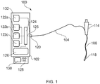
- Fig. 1 is a schematic diagram of an electrosurgical apparatus 100 that is an embodiment of the invention.
- the apparatus 100 is operable to selectively supply EM energy having a plurality of frequencies into biological tissue at a treatment site in a localised manner.
- the apparatus 100 comprises a generator 102 for generating EM energy having a plurality of frequencies.
- the generator 102 has an output port 120 to which is connected a coaxial cable 104.
- the coaxial cable 104 conveys the EM energy away from the generator 102 towards an electrosurgical instrument 118.
- the coaxial cable 104 is inserted through an instrument channel within an insertion cable 106 of a bronchoscope 114.
- the insertion cable 106 is a flexible, steerable shaft capable of non-invasive insertion into a patient's lungs.
- the instrument 118 may have a distal tip configured for percutaneous insertion, i.e. for accessing lung tissue through an incision made in the body of a patient.
- the instrument may be inserted directly into the tissue or via a suitable catheter.
- the generator 102 comprises three separate microwave sources 122a, 122b, 122c.
- Each of the separate microwave sources 122a, 122b, 122c generates a signal having a different frequency.
- the frequencies are 433 MHz, 915 MHz and 5.8 GHz.
- Each of the separate microwave sources 122a, 122b, 122c may include a corresponding power amplifier for amplifying the respective signal to a power level suitable for use.
- the three sources may be integrated into a single component, e.g. a GaN power device.
- a GaN power device such as a GaN High Electron Mobility Transistor (HEMT)-based device
- HEMT GaN High Electron Mobility Transistor
- the use of separate sources enables the cost of the generator to be kept to a minimum.
- the use of separate sources, or of a GaN power device can be selected based on application.
- the generator 102 includes a multiplexer 124 connected to receive an output signal from each of the separate microwave sources 122a, 122b, 122c.
- the multiplexer 124 operates to transfer the separate signals onto a common output path 125, which is connected to the output port 120.
- the multiplexer 124 may switch between the outputs of the separate microwave sources 122a, 122b, 122c, or may combine two or more of the outputs so that they are transmitted simultaneously.
- the multiplexer 124 may be operable as both a switch and a signal combiner.
- the generator 102 includes a controller 126 operatively connected to the multiplexer 124 and each of the separate microwave sources 122a, 122b, 122c.
- the controller 126 can control operation of the generator 102 to output a desired signal.
- a desired output signal may have a predetermined format or profile, e.g. depending on the nature (shape or size) of the treatment site.
- the controller 126 may operate to deliver EM energy according to one or more delivery profiles.
- a user may be able to select a desired profile from a plurality of stored profiles, e.g. via a user interface 128 associated with the generator 102.
- the generator may be configured in a similar manner to WO2012/076844 , which discloses an electrosurgical apparatus in which RF and microwave energy are delivered to tissue down the same instrument, according to an energy delivery profile that can be set and automatically controlled based on feedback information.
- the user interface 128 may include a display 130 for showing the selected profile and/or a stage or treatment or properties of tissue being treated.
- generator 102 is capable of switching the energy supplied to the instrument between the three frequencies, according to a desired energy delivery profile.
- the switch may first select the 2.45 GHz source, so that energy is delivered at 2.45 GHz, then switch to the 915 MHz source, so that energy is delivered at 915 MHz, and then switch to the 5.8 GHz source, so that energy is delivered at 5.8 GHz.
- the multiplexer 124 may be a time-domain multiplexer. In this case, the multiplexer can rapidly alternate the energy supplied to the instrument between the three frequencies, according to a desired energy delivery profile.
- the multiplexer 124 may be a filter multiplexer, whereby it can supply the three frequencies to the instrument simultaneously, i.e. according to an energy delivery profile having a desired mixing ratio.
- the energy delivery profile with which energy is delivered can be controlled by a combination of controlling an operational state of multiplexer 124 and the output of the separate microwave sources 122a, 122b, 122c.
- the generator 102 may include one or more reflected signal detectors arranged to measure reflected power received back from the radiating tip of the instrument 118. By comparing the reflected signal with a signal delivered from the generator to the radiating tip portion, the generator can determine dielectric properties of the material (e.g. biological tissue) in contact with the instrument 118.
- the controller may be able to adjust operation of the multiplexer 124 and the separate microwave sources 122a, 122b, 122c based on the detected reflected power.
- the generator 102 may thus dynamically control energy delivery based on detected dielectric properties of the tissue being treated.
- the controller may also be operatively connected to solenoid power source 132. Controller 126 can thereby control an output of the solenoid power source 132, thereby powering up the solenoid by a desired amount, i.e. so as to magnetize or demagnetize the magnetic material by a desired amount, and therefore change the resonant frequencies of the radiating tip portion by a desired amount.
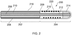
- Fig. 2 is a cross-sectional view of the distal end of an electrosurgical instrument 200 that is an embodiment of the invention.
- the electrosurgical instrument 200 comprises a coaxial cable 202 that is connected at its proximal end to a electrosurgical generator (not shown) in order to convey microwave energy.
- the coaxial cable 202 comprises an inner conductor 206, which is separated from an outer conductor 208 by a first dielectric material 210.
- the coaxial cable 202 is preferably a low loss for microwave energy.
- a choke (not shown) may be provided on the coaxial cable to inhibit back propagation of microwave energy reflected from the distal end and therefore limit backward heating along the device.
- the coaxial cable 202 terminates at its distal end with a radiating tip section 204.
- the radiating tip section 204 comprises a distal conductive section 212 of the inner conductor 206 that extends beyond a distal end 209 of the outer conductor 208.
- the distal conductive section 212 is surrounded at is distal end by a dielectric tip 214 formed from a second dielectric material, which is different from the first dielectric material 210.
- the length of the dielectric tip 214 is shorter than the length of the distal conductive section 212.
- An intermediate dielectric sleeve 216 surrounds the distal conductive section 212 between the distal end of the coaxial cable 202 and the proximal end of the dielectric tip 214.
- the intermediate dielectric sleeve 216 is formed from a third dielectric material, which is different from the first dielectric material 210 but which may be the same as the second dielectric material 214.
- the coaxial cable 202 and radiating tip section 204 have a outer sheath 218 formed over their outermost surfaces.
- the outer sheath 218 may be formed from a biocompatible material.
- the outer sheath 218 has a thickness that is small enough to ensure that it does not significantly interfere with the microwave energy radiated by the radiating tip section 204 (i.e. radiating pattern and return loss).
- the sheath is made from PTFE, although other materials are also appropriate.
- the dielectric tip 214 may be arranged to alter the shape of the radiated energy.
- the second dielectric material is selected to attenuate the radiation from the antenna, which results is a more spherical radiation pattern.
- the second dielectric material preferably has a large dielectric constant (relative permittivity ⁇ r ).
- the dielectric constant of the second dielectric material is preferably chosen to enable the length of the dielectric tip 214 to be minimised whilst still constituting a non-negligible portion of a wavelength of the microwave energy when it propagates through the second dielectric material. It is desirable for the dielectric tip to be as short as possible in order to retain flexibility in the device, especially if the second dielectric material is rigid.
- the dielectric tip may have a length equal to or less than 2 mm.
- the dielectric constant of the second dielectric material may be greater than 80, and is preferably 100 or more.
- the second dielectric material may be TiO 2 (titanium dioxide) .
- the wavelength of radiation in a material becomes shorter as the dielectric constant of the material increases. Therefore a dielectric tip 214 with a greater dielectric constant will have a greater effect on the radiation pattern.
- the larger the dielectric constant the smaller the dielectric tip 214 can be while still having a substantial effect on the shape of the radiation pattern.
- Using a dielectric tip 214 with a large dielectric constant means that the antenna can be made small and so the instrument can remain flexible.
- the dielectric constant in TiO 2 is around 100.
- the wavelength of microwave radiation having a frequency of 5.8 GHz is about 6 mm in TiO 2 compared to around 36 mm in PTFE (which may be the material used for the first and/or third dielectric materials).
- a noticeable effect on the shape of the radiation pattern can be produced in this arrangement with a dielectric tip 214 of approximately 1 mm. As the dielectric tip 214 is short, it can be made from a rigid material whilst still maintaining flexibility of the antenna as a whole.
- the dielectric tip 214 may have any suitable distal shape.
- Fig. 2 it has a dome shape, but this is not necessarily essential.
- it may be cylindrical, conical, etc.
- a smooth dome shape may be preferred because it increases the mobility of the antenna as it is manoeuvred through small channels.
- the properties of the intermediate dielectric sleeve 216 are selectable to enable the radiating tip section 204 to efficiently deliver microwave EM energy at a plurality of (e.g. at two or more) frequencies.
- the intermediate dielectric sleeve 216 is made from a material chosen to be able to exhibit different value of relative permeability ⁇ r at a first frequency and a second frequency such that the electrical length of the radiating tip section 204 is a resonant length at both the first frequency and the second frequency.
- the intermediate dielectric sleeve 216 is made from a ferrimagnetic material whose relative permeability ⁇ r is influenced by the presence of an external (biasing) magnetic field.
- the radiating tip section 204 includes a conductive coil 220 that is arranged to receive a current via a suitable feed (not shown) in the coaxial cable, e.g. from a solenoid in the generator. Current in the coil 220 induces a magnetic field across the intermediate dielectric sleeve 216.
- a suitable feed not shown
- Current in the coil 220 induces a magnetic field across the intermediate dielectric sleeve 216.
- the relative permeability of ferrimagnetic material biased in this way depends on frequency. For higher frequencies, typically equal to or greater than 1 GHz, the relative permeability tends to unity. However, for lower frequencies, it can be higher, e.g. an order of magnitude higher in some cases.
- the biasing field from the coil 220 may be controlled to enable the first frequency f 1 and the second frequency f 2 to be varied.
Landscapes
- Health & Medical Sciences (AREA)
- Surgery (AREA)
- Life Sciences & Earth Sciences (AREA)
- Biomedical Technology (AREA)
- Medical Informatics (AREA)
- Nuclear Medicine, Radiotherapy & Molecular Imaging (AREA)
- Electromagnetism (AREA)
- Engineering & Computer Science (AREA)
- Physics & Mathematics (AREA)
- Heart & Thoracic Surgery (AREA)
- Otolaryngology (AREA)
- Molecular Biology (AREA)
- Animal Behavior & Ethology (AREA)
- General Health & Medical Sciences (AREA)
- Public Health (AREA)
- Veterinary Medicine (AREA)
- Surgical Instruments (AREA)
Applications Claiming Priority (2)
| Application Number | Priority Date | Filing Date | Title |
|---|---|---|---|
| GB1705172.3A GB2560973A (en) | 2017-03-30 | 2017-03-30 | Electrosurgical instrument |
| PCT/EP2018/058092 WO2018178244A1 (en) | 2017-03-30 | 2018-03-29 | Electrosurgical instrument |
Publications (2)
| Publication Number | Publication Date |
|---|---|
| EP3600105A1 EP3600105A1 (en) | 2020-02-05 |
| EP3600105B1 true EP3600105B1 (en) | 2021-05-26 |
Family
ID=58682545
Family Applications (1)
| Application Number | Title | Priority Date | Filing Date |
|---|---|---|---|
| EP18717265.5A Active EP3600105B1 (en) | 2017-03-30 | 2018-03-29 | Electrosurgical instrument |
Country Status (14)
| Country | Link |
|---|---|
| US (1) | US11376068B2 (pt) |
| EP (1) | EP3600105B1 (pt) |
| JP (1) | JP7176758B2 (pt) |
| KR (1) | KR20190128148A (pt) |
| CN (1) | CN109715098B (pt) |
| AU (1) | AU2018246303A1 (pt) |
| BR (1) | BR112019003947A2 (pt) |
| CA (1) | CA3034969A1 (pt) |
| ES (1) | ES2880423T3 (pt) |
| GB (1) | GB2560973A (pt) |
| IL (1) | IL265384B (pt) |
| PT (1) | PT3600105T (pt) |
| SG (1) | SG11201901639RA (pt) |
| WO (1) | WO2018178244A1 (pt) |
Families Citing this family (4)
| Publication number | Priority date | Publication date | Assignee | Title |
|---|---|---|---|---|
| GB2594233A (en) * | 2019-12-30 | 2021-10-27 | Creo Medical Ltd | Electrosurgical generator for delivering microwave energy at multiple frequencies |
| GB2600114B (en) * | 2020-10-20 | 2023-07-19 | Exroid Tech Limited | A probe electrode |
| GB202118160D0 (en) * | 2021-12-15 | 2022-01-26 | Creo Medical Ltd | Electrosurgical system for identifying and treating biological tissue |
| GB202213954D0 (en) * | 2022-09-23 | 2022-11-09 | Creo Medical Ltd | Electrosurgical instrument and electrosurgical apparatus |
Family Cites Families (17)
| Publication number | Priority date | Publication date | Assignee | Title |
|---|---|---|---|---|
| LU65047A1 (pt) * | 1972-03-27 | 1973-10-03 | ||
| US4945912A (en) * | 1988-11-25 | 1990-08-07 | Sensor Electronics, Inc. | Catheter with radiofrequency heating applicator |
| US6409724B1 (en) * | 1999-05-28 | 2002-06-25 | Gyrus Medical Limited | Electrosurgical instrument |
| GB2416307A (en) * | 2004-07-16 | 2006-01-25 | Microsulis Ltd | Microwave applicator head with null forming conductors allowing for sensor placement |
| WO2007112102A1 (en) * | 2006-03-24 | 2007-10-04 | Micrablate | Center fed dipole for use with tissue ablation systems, devices, and methods |
| GB0620063D0 (en) * | 2006-10-10 | 2006-11-22 | Medical Device Innovations Ltd | Needle structure and method of performing needle biopsies |
| US8524190B2 (en) | 2008-05-30 | 2013-09-03 | Skyworks Solutions, Inc. | Enhanced hexagonal ferrite material and methods of preparation and use thereof |
| US20100087808A1 (en) * | 2008-10-03 | 2010-04-08 | Vivant Medical, Inc. | Combined Frequency Microwave Ablation System, Devices and Methods of Use |
| US9113924B2 (en) * | 2008-10-17 | 2015-08-25 | Covidien Lp | Choked dielectric loaded tip dipole microwave antenna |
| US8968288B2 (en) * | 2010-02-19 | 2015-03-03 | Covidien Lp | Ablation devices with dual operating frequencies, systems including same, and methods of adjusting ablation volume using same |
| GB201021032D0 (en) * | 2010-12-10 | 2011-01-26 | Creo Medical Ltd | Electrosurgical apparatus |
| EP2609887A1 (en) * | 2011-12-29 | 2013-07-03 | Koninklijke Philips Electronics N.V. | Electrosurgical ablation apparatus |
| GB201321710D0 (en) * | 2013-12-09 | 2014-01-22 | Creo Medical Ltd | Electrosurgical apparatus |
| GB2541749B (en) * | 2015-08-31 | 2020-12-09 | Emblation Ltd | An interference suppression apparatus and method |
| WO2017158603A1 (en) * | 2016-03-15 | 2017-09-21 | Nimd Ltd. | Localized hyperthermia/thermal ablation for cancer treatment |
| US10524821B2 (en) * | 2016-09-23 | 2020-01-07 | Lumenis | System and method for morcellation of tissue |
| WO2018140816A1 (en) * | 2017-01-26 | 2018-08-02 | Broncus Medical Inc. | Bronchoscopic-based microwave ablation system and method |
-
2017
- 2017-03-30 GB GB1705172.3A patent/GB2560973A/en not_active Withdrawn
-
2018
- 2018-03-29 KR KR1020197007834A patent/KR20190128148A/ko not_active Application Discontinuation
- 2018-03-29 JP JP2019515521A patent/JP7176758B2/ja active Active
- 2018-03-29 PT PT187172655T patent/PT3600105T/pt unknown
- 2018-03-29 CN CN201880003597.1A patent/CN109715098B/zh active Active
- 2018-03-29 CA CA3034969A patent/CA3034969A1/en active Pending
- 2018-03-29 BR BR112019003947-3A patent/BR112019003947A2/pt not_active IP Right Cessation
- 2018-03-29 SG SG11201901639RA patent/SG11201901639RA/en unknown
- 2018-03-29 AU AU2018246303A patent/AU2018246303A1/en not_active Abandoned
- 2018-03-29 EP EP18717265.5A patent/EP3600105B1/en active Active
- 2018-03-29 ES ES18717265T patent/ES2880423T3/es active Active
- 2018-03-29 US US16/328,682 patent/US11376068B2/en active Active
- 2018-03-29 IL IL265384A patent/IL265384B/en unknown
- 2018-03-29 WO PCT/EP2018/058092 patent/WO2018178244A1/en unknown
Non-Patent Citations (1)
| Title |
|---|
| None * |
Also Published As
| Publication number | Publication date |
|---|---|
| US11376068B2 (en) | 2022-07-05 |
| US20190201095A1 (en) | 2019-07-04 |
| IL265384B (en) | 2022-08-01 |
| CN109715098B (zh) | 2021-11-05 |
| BR112019003947A2 (pt) | 2019-05-21 |
| GB201705172D0 (en) | 2017-05-17 |
| CN109715098A (zh) | 2019-05-03 |
| CA3034969A1 (en) | 2018-10-04 |
| WO2018178244A1 (en) | 2018-10-04 |
| GB2560973A (en) | 2018-10-03 |
| ES2880423T3 (es) | 2021-11-24 |
| KR20190128148A (ko) | 2019-11-15 |
| PT3600105T (pt) | 2021-07-14 |
| SG11201901639RA (en) | 2019-03-28 |
| JP2020512022A (ja) | 2020-04-23 |
| AU2018246303A1 (en) | 2019-04-11 |
| EP3600105A1 (en) | 2020-02-05 |
| IL265384A (en) | 2019-05-30 |
| JP7176758B2 (ja) | 2022-11-22 |
Similar Documents
| Publication | Publication Date | Title |
|---|---|---|
| EP3600105B1 (en) | Electrosurgical instrument | |
| EP3086730B1 (en) | Surgical snare with ability to deliver electromagnetic energy and/or thermal plasma into biological tissue | |
| EP3579777B1 (en) | Electrosurgical apparatus and electrosurgical instrument | |
| AU2014267060B2 (en) | Dual-function plasma and non-ionising microwave coagulating electrosurgical instrument and electrosurgical apparatus incorporating the same | |
| EP4031047B1 (en) | Electrosurgical apparatus for treating biological tissue with microwave energy |
Legal Events
| Date | Code | Title | Description |
|---|---|---|---|
| STAA | Information on the status of an ep patent application or granted ep patent |
Free format text: STATUS: UNKNOWN |
|
| STAA | Information on the status of an ep patent application or granted ep patent |
Free format text: STATUS: THE INTERNATIONAL PUBLICATION HAS BEEN MADE |
|
| PUAI | Public reference made under article 153(3) epc to a published international application that has entered the european phase |
Free format text: ORIGINAL CODE: 0009012 |
|
| STAA | Information on the status of an ep patent application or granted ep patent |
Free format text: STATUS: REQUEST FOR EXAMINATION WAS MADE |
|
| 17P | Request for examination filed |
Effective date: 20190327 |
|
| AK | Designated contracting states |
Kind code of ref document: A1 Designated state(s): AL AT BE BG CH CY CZ DE DK EE ES FI FR GB GR HR HU IE IS IT LI LT LU LV MC MK MT NL NO PL PT RO RS SE SI SK SM TR |
|
| AX | Request for extension of the european patent |
Extension state: BA ME |
|
| DAV | Request for validation of the european patent (deleted) | ||
| DAX | Request for extension of the european patent (deleted) | ||
| GRAP | Despatch of communication of intention to grant a patent |
Free format text: ORIGINAL CODE: EPIDOSNIGR1 |
|
| STAA | Information on the status of an ep patent application or granted ep patent |
Free format text: STATUS: GRANT OF PATENT IS INTENDED |
|
| INTG | Intention to grant announced |
Effective date: 20201211 |
|
| GRAS | Grant fee paid |
Free format text: ORIGINAL CODE: EPIDOSNIGR3 |
|
| GRAA | (expected) grant |
Free format text: ORIGINAL CODE: 0009210 |
|
| STAA | Information on the status of an ep patent application or granted ep patent |
Free format text: STATUS: THE PATENT HAS BEEN GRANTED |
|
| AK | Designated contracting states |
Kind code of ref document: B1 Designated state(s): AL AT BE BG CH CY CZ DE DK EE ES FI FR GB GR HR HU IE IS IT LI LT LU LV MC MK MT NL NO PL PT RO RS SE SI SK SM TR |
|
| REG | Reference to a national code |
Ref country code: GB Ref legal event code: FG4D |
|
| REG | Reference to a national code |
Ref country code: CH Ref legal event code: EP |
|
| REG | Reference to a national code |
Ref country code: AT Ref legal event code: REF Ref document number: 1395428 Country of ref document: AT Kind code of ref document: T Effective date: 20210615 |
|
| REG | Reference to a national code |
Ref country code: DE Ref legal event code: R096 Ref document number: 602018017689 Country of ref document: DE |
|
| REG | Reference to a national code |
Ref country code: IE Ref legal event code: FG4D |
|
| REG | Reference to a national code |
Ref country code: PT Ref legal event code: SC4A Ref document number: 3600105 Country of ref document: PT Date of ref document: 20210714 Kind code of ref document: T Free format text: AVAILABILITY OF NATIONAL TRANSLATION Effective date: 20210707 |
|
| REG | Reference to a national code |
Ref country code: NL Ref legal event code: FP |
|
| REG | Reference to a national code |
Ref country code: LT Ref legal event code: MG9D |
|
| PG25 | Lapsed in a contracting state [announced via postgrant information from national office to epo] |
Ref country code: BG Free format text: LAPSE BECAUSE OF FAILURE TO SUBMIT A TRANSLATION OF THE DESCRIPTION OR TO PAY THE FEE WITHIN THE PRESCRIBED TIME-LIMIT Effective date: 20210826 Ref country code: FI Free format text: LAPSE BECAUSE OF FAILURE TO SUBMIT A TRANSLATION OF THE DESCRIPTION OR TO PAY THE FEE WITHIN THE PRESCRIBED TIME-LIMIT Effective date: 20210526 Ref country code: HR Free format text: LAPSE BECAUSE OF FAILURE TO SUBMIT A TRANSLATION OF THE DESCRIPTION OR TO PAY THE FEE WITHIN THE PRESCRIBED TIME-LIMIT Effective date: 20210526 Ref country code: LT Free format text: LAPSE BECAUSE OF FAILURE TO SUBMIT A TRANSLATION OF THE DESCRIPTION OR TO PAY THE FEE WITHIN THE PRESCRIBED TIME-LIMIT Effective date: 20210526 |
|
| REG | Reference to a national code |
Ref country code: ES Ref legal event code: FG2A Ref document number: 2880423 Country of ref document: ES Kind code of ref document: T3 Effective date: 20211124 |
|
| PG25 | Lapsed in a contracting state [announced via postgrant information from national office to epo] |
Ref country code: GR Free format text: LAPSE BECAUSE OF FAILURE TO SUBMIT A TRANSLATION OF THE DESCRIPTION OR TO PAY THE FEE WITHIN THE PRESCRIBED TIME-LIMIT Effective date: 20210827 Ref country code: IS Free format text: LAPSE BECAUSE OF FAILURE TO SUBMIT A TRANSLATION OF THE DESCRIPTION OR TO PAY THE FEE WITHIN THE PRESCRIBED TIME-LIMIT Effective date: 20210926 Ref country code: PL Free format text: LAPSE BECAUSE OF FAILURE TO SUBMIT A TRANSLATION OF THE DESCRIPTION OR TO PAY THE FEE WITHIN THE PRESCRIBED TIME-LIMIT Effective date: 20210526 Ref country code: LV Free format text: LAPSE BECAUSE OF FAILURE TO SUBMIT A TRANSLATION OF THE DESCRIPTION OR TO PAY THE FEE WITHIN THE PRESCRIBED TIME-LIMIT Effective date: 20210526 Ref country code: NO Free format text: LAPSE BECAUSE OF FAILURE TO SUBMIT A TRANSLATION OF THE DESCRIPTION OR TO PAY THE FEE WITHIN THE PRESCRIBED TIME-LIMIT Effective date: 20210826 Ref country code: SE Free format text: LAPSE BECAUSE OF FAILURE TO SUBMIT A TRANSLATION OF THE DESCRIPTION OR TO PAY THE FEE WITHIN THE PRESCRIBED TIME-LIMIT Effective date: 20210526 Ref country code: RS Free format text: LAPSE BECAUSE OF FAILURE TO SUBMIT A TRANSLATION OF THE DESCRIPTION OR TO PAY THE FEE WITHIN THE PRESCRIBED TIME-LIMIT Effective date: 20210526 |
|
| REG | Reference to a national code |
Ref country code: AT Ref legal event code: UEP Ref document number: 1395428 Country of ref document: AT Kind code of ref document: T Effective date: 20210526 |
|
| PG25 | Lapsed in a contracting state [announced via postgrant information from national office to epo] |
Ref country code: CZ Free format text: LAPSE BECAUSE OF FAILURE TO SUBMIT A TRANSLATION OF THE DESCRIPTION OR TO PAY THE FEE WITHIN THE PRESCRIBED TIME-LIMIT Effective date: 20210526 Ref country code: DK Free format text: LAPSE BECAUSE OF FAILURE TO SUBMIT A TRANSLATION OF THE DESCRIPTION OR TO PAY THE FEE WITHIN THE PRESCRIBED TIME-LIMIT Effective date: 20210526 Ref country code: RO Free format text: LAPSE BECAUSE OF FAILURE TO SUBMIT A TRANSLATION OF THE DESCRIPTION OR TO PAY THE FEE WITHIN THE PRESCRIBED TIME-LIMIT Effective date: 20210526 Ref country code: EE Free format text: LAPSE BECAUSE OF FAILURE TO SUBMIT A TRANSLATION OF THE DESCRIPTION OR TO PAY THE FEE WITHIN THE PRESCRIBED TIME-LIMIT Effective date: 20210526 Ref country code: SM Free format text: LAPSE BECAUSE OF FAILURE TO SUBMIT A TRANSLATION OF THE DESCRIPTION OR TO PAY THE FEE WITHIN THE PRESCRIBED TIME-LIMIT Effective date: 20210526 Ref country code: SK Free format text: LAPSE BECAUSE OF FAILURE TO SUBMIT A TRANSLATION OF THE DESCRIPTION OR TO PAY THE FEE WITHIN THE PRESCRIBED TIME-LIMIT Effective date: 20210526 |
|
| REG | Reference to a national code |
Ref country code: DE Ref legal event code: R097 Ref document number: 602018017689 Country of ref document: DE |
|
| PLBE | No opposition filed within time limit |
Free format text: ORIGINAL CODE: 0009261 |
|
| STAA | Information on the status of an ep patent application or granted ep patent |
Free format text: STATUS: NO OPPOSITION FILED WITHIN TIME LIMIT |
|
| PGFP | Annual fee paid to national office [announced via postgrant information from national office to epo] |
Ref country code: CH Payment date: 20220325 Year of fee payment: 5 |
|
| 26N | No opposition filed |
Effective date: 20220301 |
|
| PG25 | Lapsed in a contracting state [announced via postgrant information from national office to epo] |
Ref country code: IS Free format text: LAPSE BECAUSE OF FAILURE TO SUBMIT A TRANSLATION OF THE DESCRIPTION OR TO PAY THE FEE WITHIN THE PRESCRIBED TIME-LIMIT Effective date: 20210926 Ref country code: AL Free format text: LAPSE BECAUSE OF FAILURE TO SUBMIT A TRANSLATION OF THE DESCRIPTION OR TO PAY THE FEE WITHIN THE PRESCRIBED TIME-LIMIT Effective date: 20210526 |
|
| PGFP | Annual fee paid to national office [announced via postgrant information from national office to epo] |
Ref country code: PT Payment date: 20220307 Year of fee payment: 5 Ref country code: NL Payment date: 20220325 Year of fee payment: 5 |
|
| PG25 | Lapsed in a contracting state [announced via postgrant information from national office to epo] |
Ref country code: MC Free format text: LAPSE BECAUSE OF FAILURE TO SUBMIT A TRANSLATION OF THE DESCRIPTION OR TO PAY THE FEE WITHIN THE PRESCRIBED TIME-LIMIT Effective date: 20210526 |
|
| REG | Reference to a national code |
Ref country code: BE Ref legal event code: MM Effective date: 20220331 |
|
| PG25 | Lapsed in a contracting state [announced via postgrant information from national office to epo] |
Ref country code: LU Free format text: LAPSE BECAUSE OF NON-PAYMENT OF DUE FEES Effective date: 20220329 |
|
| PG25 | Lapsed in a contracting state [announced via postgrant information from national office to epo] |
Ref country code: BE Free format text: LAPSE BECAUSE OF NON-PAYMENT OF DUE FEES Effective date: 20220331 |
|
| REG | Reference to a national code |
Ref country code: CH Ref legal event code: PL |
|
| REG | Reference to a national code |
Ref country code: NL Ref legal event code: MM Effective date: 20230401 |
|
| PG25 | Lapsed in a contracting state [announced via postgrant information from national office to epo] |
Ref country code: PT Free format text: LAPSE BECAUSE OF NON-PAYMENT OF DUE FEES Effective date: 20230929 |
|
| PG25 | Lapsed in a contracting state [announced via postgrant information from national office to epo] |
Ref country code: NL Free format text: LAPSE BECAUSE OF NON-PAYMENT OF DUE FEES Effective date: 20230401 |
|
| PG25 | Lapsed in a contracting state [announced via postgrant information from national office to epo] |
Ref country code: LI Free format text: LAPSE BECAUSE OF NON-PAYMENT OF DUE FEES Effective date: 20230331 Ref country code: CH Free format text: LAPSE BECAUSE OF NON-PAYMENT OF DUE FEES Effective date: 20230331 |
|
| PGFP | Annual fee paid to national office [announced via postgrant information from national office to epo] |
Ref country code: IE Payment date: 20240320 Year of fee payment: 7 |
|
| PG25 | Lapsed in a contracting state [announced via postgrant information from national office to epo] |
Ref country code: MK Free format text: LAPSE BECAUSE OF FAILURE TO SUBMIT A TRANSLATION OF THE DESCRIPTION OR TO PAY THE FEE WITHIN THE PRESCRIBED TIME-LIMIT Effective date: 20210526 Ref country code: CY Free format text: LAPSE BECAUSE OF FAILURE TO SUBMIT A TRANSLATION OF THE DESCRIPTION OR TO PAY THE FEE WITHIN THE PRESCRIBED TIME-LIMIT Effective date: 20210526 |
|
| PGFP | Annual fee paid to national office [announced via postgrant information from national office to epo] |
Ref country code: DE Payment date: 20240320 Year of fee payment: 7 Ref country code: GB Payment date: 20240320 Year of fee payment: 7 |
|
| REG | Reference to a national code |
Ref country code: AT Ref legal event code: MM01 Ref document number: 1395428 Country of ref document: AT Kind code of ref document: T Effective date: 20230329 |
|
| PG25 | Lapsed in a contracting state [announced via postgrant information from national office to epo] |
Ref country code: HU Free format text: LAPSE BECAUSE OF FAILURE TO SUBMIT A TRANSLATION OF THE DESCRIPTION OR TO PAY THE FEE WITHIN THE PRESCRIBED TIME-LIMIT; INVALID AB INITIO Effective date: 20180329 |
|
| PGFP | Annual fee paid to national office [announced via postgrant information from national office to epo] |
Ref country code: IT Payment date: 20240326 Year of fee payment: 7 Ref country code: FR Payment date: 20240320 Year of fee payment: 7 |
|
| PGFP | Annual fee paid to national office [announced via postgrant information from national office to epo] |
Ref country code: ES Payment date: 20240401 Year of fee payment: 7 |
|
| PG25 | Lapsed in a contracting state [announced via postgrant information from national office to epo] |
Ref country code: AT Free format text: LAPSE BECAUSE OF NON-PAYMENT OF DUE FEES Effective date: 20230329 |
|
| PG25 | Lapsed in a contracting state [announced via postgrant information from national office to epo] |
Ref country code: AT Free format text: LAPSE BECAUSE OF NON-PAYMENT OF DUE FEES Effective date: 20230329 |