EP3600017B1 - Cranial fixation device - Google Patents
Cranial fixation device Download PDFInfo
- Publication number
- EP3600017B1 EP3600017B1 EP18777009.4A EP18777009A EP3600017B1 EP 3600017 B1 EP3600017 B1 EP 3600017B1 EP 18777009 A EP18777009 A EP 18777009A EP 3600017 B1 EP3600017 B1 EP 3600017B1
- Authority
- EP
- European Patent Office
- Prior art keywords
- base
- cap
- wings
- pair
- opening
- Prior art date
- Legal status (The legal status is an assumption and is not a legal conclusion. Google has not performed a legal analysis and makes no representation as to the accuracy of the status listed.)
- Active
Links
Images




Classifications
-
- A—HUMAN NECESSITIES
- A61—MEDICAL OR VETERINARY SCIENCE; HYGIENE
- A61B—DIAGNOSIS; SURGERY; IDENTIFICATION
- A61B90/00—Instruments, implements or accessories specially adapted for surgery or diagnosis and not covered by any of the groups A61B1/00 - A61B50/00, e.g. for luxation treatment or for protecting wound edges
- A61B90/10—Instruments, implements or accessories specially adapted for surgery or diagnosis and not covered by any of the groups A61B1/00 - A61B50/00, e.g. for luxation treatment or for protecting wound edges for stereotaxic surgery, e.g. frame-based stereotaxis
- A61B90/14—Fixators for body parts, e.g. skull clamps; Constructional details of fixators, e.g. pins
-
- A—HUMAN NECESSITIES
- A61—MEDICAL OR VETERINARY SCIENCE; HYGIENE
- A61M—DEVICES FOR INTRODUCING MEDIA INTO, OR ONTO, THE BODY; DEVICES FOR TRANSDUCING BODY MEDIA OR FOR TAKING MEDIA FROM THE BODY; DEVICES FOR PRODUCING OR ENDING SLEEP OR STUPOR
- A61M25/00—Catheters; Hollow probes
- A61M25/01—Introducing, guiding, advancing, emplacing or holding catheters
- A61M25/02—Holding devices, e.g. on the body
-
- A—HUMAN NECESSITIES
- A61—MEDICAL OR VETERINARY SCIENCE; HYGIENE
- A61B—DIAGNOSIS; SURGERY; IDENTIFICATION
- A61B17/00—Surgical instruments, devices or methods
- A61B17/34—Trocars; Puncturing needles
- A61B2017/347—Locking means, e.g. for locking instrument in cannula
-
- A—HUMAN NECESSITIES
- A61—MEDICAL OR VETERINARY SCIENCE; HYGIENE
- A61B—DIAGNOSIS; SURGERY; IDENTIFICATION
- A61B17/00—Surgical instruments, devices or methods
- A61B17/34—Trocars; Puncturing needles
- A61B2017/348—Means for supporting the trocar against the body or retaining the trocar inside the body
- A61B2017/3482—Means for supporting the trocar against the body or retaining the trocar inside the body inside
- A61B2017/349—Trocar with thread on outside
-
- A—HUMAN NECESSITIES
- A61—MEDICAL OR VETERINARY SCIENCE; HYGIENE
- A61B—DIAGNOSIS; SURGERY; IDENTIFICATION
- A61B90/00—Instruments, implements or accessories specially adapted for surgery or diagnosis and not covered by any of the groups A61B1/00 - A61B50/00, e.g. for luxation treatment or for protecting wound edges
- A61B90/03—Automatic limiting or abutting means, e.g. for safety
- A61B2090/031—Automatic limiting or abutting means, e.g. for safety torque limiting
-
- A—HUMAN NECESSITIES
- A61—MEDICAL OR VETERINARY SCIENCE; HYGIENE
- A61B—DIAGNOSIS; SURGERY; IDENTIFICATION
- A61B90/00—Instruments, implements or accessories specially adapted for surgery or diagnosis and not covered by any of the groups A61B1/00 - A61B50/00, e.g. for luxation treatment or for protecting wound edges
- A61B90/03—Automatic limiting or abutting means, e.g. for safety
- A61B2090/033—Abutting means, stops, e.g. abutting on tissue or skin
- A61B2090/034—Abutting means, stops, e.g. abutting on tissue or skin abutting on parts of the device itself
- A61B2090/035—Abutting means, stops, e.g. abutting on tissue or skin abutting on parts of the device itself preventing further rotation
-
- A—HUMAN NECESSITIES
- A61—MEDICAL OR VETERINARY SCIENCE; HYGIENE
- A61B—DIAGNOSIS; SURGERY; IDENTIFICATION
- A61B90/00—Instruments, implements or accessories specially adapted for surgery or diagnosis and not covered by any of the groups A61B1/00 - A61B50/00, e.g. for luxation treatment or for protecting wound edges
- A61B90/08—Accessories or related features not otherwise provided for
- A61B2090/0807—Indication means
- A61B2090/0808—Indication means for indicating correct assembly of components, e.g. of the surgical apparatus
-
- A—HUMAN NECESSITIES
- A61—MEDICAL OR VETERINARY SCIENCE; HYGIENE
- A61B—DIAGNOSIS; SURGERY; IDENTIFICATION
- A61B90/00—Instruments, implements or accessories specially adapted for surgery or diagnosis and not covered by any of the groups A61B1/00 - A61B50/00, e.g. for luxation treatment or for protecting wound edges
- A61B90/08—Accessories or related features not otherwise provided for
- A61B2090/0807—Indication means
- A61B2090/0811—Indication means for the position of a particular part of an instrument with respect to the rest of the instrument, e.g. position of the anvil of a stapling instrument
- A61B2090/0812—Indication means for the position of a particular part of an instrument with respect to the rest of the instrument, e.g. position of the anvil of a stapling instrument indicating loosening or shifting of parts of an instrument, signaling maladjustment of parts
-
- A—HUMAN NECESSITIES
- A61—MEDICAL OR VETERINARY SCIENCE; HYGIENE
- A61B—DIAGNOSIS; SURGERY; IDENTIFICATION
- A61B90/00—Instruments, implements or accessories specially adapted for surgery or diagnosis and not covered by any of the groups A61B1/00 - A61B50/00, e.g. for luxation treatment or for protecting wound edges
- A61B90/10—Instruments, implements or accessories specially adapted for surgery or diagnosis and not covered by any of the groups A61B1/00 - A61B50/00, e.g. for luxation treatment or for protecting wound edges for stereotaxic surgery, e.g. frame-based stereotaxis
- A61B2090/103—Cranial plugs for access to brain
-
- A—HUMAN NECESSITIES
- A61—MEDICAL OR VETERINARY SCIENCE; HYGIENE
- A61M—DEVICES FOR INTRODUCING MEDIA INTO, OR ONTO, THE BODY; DEVICES FOR TRANSDUCING BODY MEDIA OR FOR TAKING MEDIA FROM THE BODY; DEVICES FOR PRODUCING OR ENDING SLEEP OR STUPOR
- A61M25/00—Catheters; Hollow probes
- A61M25/01—Introducing, guiding, advancing, emplacing or holding catheters
- A61M25/02—Holding devices, e.g. on the body
- A61M2025/024—Holding devices, e.g. on the body having a clip or clamp system
-
- A—HUMAN NECESSITIES
- A61—MEDICAL OR VETERINARY SCIENCE; HYGIENE
- A61M—DEVICES FOR INTRODUCING MEDIA INTO, OR ONTO, THE BODY; DEVICES FOR TRANSDUCING BODY MEDIA OR FOR TAKING MEDIA FROM THE BODY; DEVICES FOR PRODUCING OR ENDING SLEEP OR STUPOR
- A61M25/00—Catheters; Hollow probes
- A61M25/01—Introducing, guiding, advancing, emplacing or holding catheters
- A61M25/02—Holding devices, e.g. on the body
- A61M2025/028—Holding devices, e.g. on the body having a mainly rigid support structure
-
- A—HUMAN NECESSITIES
- A61—MEDICAL OR VETERINARY SCIENCE; HYGIENE
- A61M—DEVICES FOR INTRODUCING MEDIA INTO, OR ONTO, THE BODY; DEVICES FOR TRANSDUCING BODY MEDIA OR FOR TAKING MEDIA FROM THE BODY; DEVICES FOR PRODUCING OR ENDING SLEEP OR STUPOR
- A61M25/00—Catheters; Hollow probes
- A61M25/01—Introducing, guiding, advancing, emplacing or holding catheters
- A61M25/02—Holding devices, e.g. on the body
- A61M2025/0286—Holding devices, e.g. on the body anchored in the skin by suture or other skin penetrating devices
-
- A—HUMAN NECESSITIES
- A61—MEDICAL OR VETERINARY SCIENCE; HYGIENE
- A61M—DEVICES FOR INTRODUCING MEDIA INTO, OR ONTO, THE BODY; DEVICES FOR TRANSDUCING BODY MEDIA OR FOR TAKING MEDIA FROM THE BODY; DEVICES FOR PRODUCING OR ENDING SLEEP OR STUPOR
- A61M2210/00—Anatomical parts of the body
- A61M2210/06—Head
- A61M2210/0687—Skull, cranium
Definitions
- This disclosure relates to cranial fixation devices or bolts for securing medical devices to the head and methods of operation thereof.
- Cranial fixation devices are used to secure medical devices to the head and control the depth of the medical devices inserted into the brain within the skull.
- the medical devices can include a catheter or probe.
- the catheter or probe is introduced into a lumen or hole of the fixation device and into a corresponding hole in the skull.
- the catheter or probe is secured to the skull by threading the cranial fixation device into the cranium and crimping the catheter or probe cable with compression.
- the inventors noticed that currently available compression type fittings and fixation devices used to crimp the catheter or probe cable do not have a positive stop or any visual means of knowing when the cable of a medical device is properly clamped. This results in either over or under compression.
- the compression fitting or fixation device is not tightened enough, the cable can slip, however, when over compressed or tighten, signal interference may occur.
- over compression may cause interference or breaks in the optical signal.
- Some cranial fixation devices use Luer-type fitting connections. However, when using a Luer-type fitting connection, the catheter or probe depth cannot be adjusted.
- a catheter guiding device including a bolt including a shaft configured to be inserted within a hole drilled in a bone and a passageway extending longitudinally therethrough along a bolt axis and a guide member received within the passageway of the bolt and extending longitudinally along a guide axis.
- the apparatus comprises a probe held in the passage channel of a skull bolt in a drilling through the skull.
- the passage channel and the probe have out-of-round cross sections, which lock together, to prevent rotation at least along part of their lengths.
- a cranial fixation device comprising a cap, a base and a compression grommet.
- the cap comprises a central body having a mating connector with a threaded portion projecting from a distal end of the central body, a pair of wings extending radially out from the central body and a first opening extending from a proximal end of the central body to the distal end of the central body and through the threaded portion of the mating connector.
- the base comprises a threaded central opening corresponding to the threaded portion of the mating connector, a distal threaded portion configured to engage with an opening in a skull, a pair of wings extending radially out from the threaded central opening and a second opening extending through the threaded central opening and the distal threaded portion.
- the threaded central opening is positioned on a proximal end of the base.
- the compression grommet is configured to be placed into the threaded central opening of the base.
- the compression grommet has a third opening extending from the proximal end to the distal end of the compression grommet.
- the openings e.g., the first opening, the second opening and the third opening, are aligned when the cap mates with the base and forms an instrument lumen configured to accept a portion of an instrument cable.
- the threaded portion of the cap is configured to mate with the threaded central opening of the base.
- At least one of the wings of the pair of wings of the cap has a projection protruding in a direction towards the base. Additionally, the each wing of the pair of wings of the base has a seat.
- the projection from at least one wing of the pair of wings of the cap and at least one of the seats in the pair of wings of the base are configured to create a torque stop when a predetermined compression of the compression grommet is applied by tightening the cap on the base.
- the compression grommet compresses against the instrument cable fixing the instrument cable in place at a determined depth.
- a cranial fixation device comprising a base.
- the base comprises a threaded central opening, a distal threaded portion, an opening and a pair of wings.
- the threaded central opening is positioned on a proximal end of the base and configured to mate with a mating connector of a cap.
- the distal threaded portion is configured to engage with an opening in a skull.
- the opening extending through the threaded central opening and the distal threaded portion.
- the opening is configured to receive a portion of an instrument cable.
- the pair of wings extend radially out from the threaded central opening. Each wing has a notch configured to receive another portion of the instrument cable.
- a cranial fixation device comprising a cap, a base and a compression grommet.
- the cap comprises a central body having a mating connector with a threaded portion projecting from a distal end of the central body and a first opening extending from a proximal end of the central body to the distal end of the central body and through the threaded portion of the mating connector.
- the base comprises a threaded central opening corresponding to the threaded portion of the mating connector, a distal threaded portion configured to engage with an opening in a skull, a pair of wings extending radially out from the threaded central opening and a second opening extending through the threaded central opening and the distal threaded portion.
- the threaded central opening is positioned on a proximal end of the base.
- the compression grommet is configured to be placed into the threaded central opening of the base.
- the compression grommet has a third opening extending from the proximal end to the distal end of the compression grommet.
- Each opening e.g., the first opening, the second opening and the third opening, is aligned when the cap mates with the base and forms an instrument lumen configured to accept a portion of an instrument cable.
- the threaded portion of the cap is configured to mate with the threaded central opening of the base.
- the dimensions of the threaded central opening and the threaded portion are configured to create a torque stop when a predetermined compression of the compression grommet is applied by tightening the cap on the base.
- the compression grommet compresses against the instrument cable fixing the instrument cable in place at a determined depth.
- the cranial fixation device 100 comprises a cap 105, a base 110 and a compression grommet 115.
- the base 110 has a hollow distal threaded portion 132 for securing the cranial fixation device 100 into a hole in a skull. The hole is preformed.
- the distal threaded portion 132 is hollow having an opening that is dimensioned to allow a portion of the cable of the medical device to be inserted there through.
- the base 110 also has a body having a threaded central opening 130.
- the threaded central opening 130 has a female threading.
- the female threading is for mating with a male threading in the cap 105.
- the threaded central opening 130 is dimensioned to allow the cable of the medical device to be inserted there through.
- the opening of the distal threaded portion 132 and the opening of the threaded central opening are aligned.
- the compression grommet 115 is dimensioned to be insertable into the opening of the threaded central opening 130.
- the compression grommet 115 has an opening going through from the proximal to the distal end thereof. When inserted into the threaded central opening 130, the opening of the compression grommet 115 is also aligned with opening of the distal threaded portion 132 and the opening of the threaded central opening.
- the compression grommet 115 can be made from silicone.
- the body of the base 110 has wings 140 extending outward to facilitate securing the base into the hole of the skull.
- each wing 140 including notches 135.
- the notches 135 are located on the distal side of each wing 140.
- the notches 135 are configured and dimensioned to respectively receive a portion of a cable of medical device.
- Each notch 135 has a slot or opening that allows for the cable to be inserted. Once inserted, the cable is loosely secured within the notch 135.
- the notches 135 provide a strain relief for the cable.
- the notches are located symmetrically on the wings 140 with respect to the center of the fixation device, however, the location of the notches are not required to be symmetric.
- the cap 105 also has wings 128 extending outward to facilitate securing the cap to the base. As shown in Fig. 4 (closed position), the size of the wings 128 in the longitudinal direction of the cap is the same size as the wings 140 of the base in the longitudinal direction.
- the cap 105 has a central body 125.
- the central body 125 has a generally cylindrical shape.
- the wings 128 extend outward from the central body 125.
- the central body 125 has an opening 126 extending therethrough. The opening extends from the proximal end to the distal end.
- the opening 126 is tapered.
- the opening 126 is larger on the proximal end than on the distal end.
- the tapered opening provides a benefit of preventing the cable of a medical device when it is inserted into the opening from bending at a right angle. For example, if the opening was not tapered, but rather straight, when a cable is inserted into the opening, the cable could be bent at a steep angle, which could result in the cable severing or having signal interference.
- the cap 105 also includes a threaded portion 127 (mating connector with threading).
- the threaded portion 127 extends or projects distally from the central body 125. As shown in Fig. 1 , the threaded portion 127 is a male threaded portion. When the cap 105 is placed on the base 110 and screwed on to secure the same to the base, the threaded portion 127 mates with the female threading of the threaded central opening 130 as will be described in detail later.
- the threaded portion 127 also has an opening.
- the opening of the threaded portion 127 and the opening 126 of the central body 125 are aligned such that a cable of a medical device can be inserted therethrough.
- At least one of the wings 128 of the cap 105 has a distal projection 120.
- Each wing 140 of the base 110 has a corresponding indentation or seat 145.
- the cranial fixation device 100 has two projections 120, one on each wing 128 of the cap and two respective seats 145, one on each wing 140 of the base.
- two projections 120 on the cap 105 are not required.
- the cap 105 can have one distal projection 120 on a wing 128.
- the dimensions of the at least one projection on the wings 128 matches the dimensions of the seats 145 on the wings 140 of the base.
- the combination of the at least one projection 120 and seats 145 of the wings of the base form a positive stop for the compression. Since the dimensions of the at least one projection and seats match, when mated, the distal end of the wings of the cap 105 and the proximal ends of the wings of the base 110 can be flush against each other when fully compressed and locked, e.g., closed position (see Fig. 4 ). This provides both a visual and tactile indication when desired compression is applied.
- the length of the threading in both the threaded portion 127 and the threaded central opening 130 is set such that a predetermined compression can be applied to the medical device.
- the length of the respective threading is set such that when mated, the distal end of the wings of the cap and the proximal ends of the wings of the base can be flush against each other when fully compressed and locked, e.g., closed position, when a predetermined compression is applied (see Fig. 4 ).
- the predetermined compression is applied, the respective wings (of the cap and base are aligned). This also gives a visual indication when the desired (predetermined) compression has been applied.
- the combination of the at least one projection and corresponding seats 145 and the length of the threading provides a positive stop with tactical and visual indications when a predetermined compression is applied.
- the disclosed cranial fixation device 100 allows for a repeatable compression of a medical device (cable thereof) without the problem of over or under tightening.
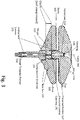
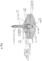
- Figs 3-4 are sectional views of the cranial fixation device 100 along the E-E line of Fig. 2 .
- Fig. 3 depicts a sectional view of the cranial fixation device 100 in an opened state, e.g., not compressed.
- Fig. 4 depicts a sectional view of the cranial fixation device 100 in a closed state, e.g., compressed.
- the medical device cable 300 is depicted as a dashed line traversing the instrument lumen 305.
- the cap 105 In the opened state, not compressed, the cap 105 is positioned to contact the compression grommet 115.
- the threaded portion 127 of the cap 105 is partially mated with the threaded central opening 130.
- the operator or user twists or turns the wings 128 of the cap 105 to compress the compression grommet 115.
- Closing will occur once the medical device is position at a desired location with the skull, e.g., desired depth.
- the threaded portion 127 of the cap further mates with the threaded central opening 130 of the base.
- the wings 128 of the cap 105 are twisted or turned until the projections 120 of the cap 120 engage with the seats 145 of the base 110.
- the threaded portion 127 of the cap will be fully mated with the threaded central opening 130 of the base as shown in Fig. 4.
- Fig 4 also shows the projections 120 of the cap engaged with the seats 145 of the base 110.
- the cable 300 is secured in position.
- Fig. 5 also depicts the cranial fixation device 100 in a closed position, e.g. compressed.
- Fig. 5 also shows the cable 300 inserted into the respective notches 135 of wings of the base 100.
- the cable 300 is also shown as being inserted into the lumen 305.
- the cable 300 extends between the respective notches 135 which provide strain relief.
- the cranial fixation device 100 is shown with both projections 120, seats 145 and notches 135, in another aspect of the disclosure, the notches can be removed.
- the base 110 of the cranial fixation device 100 is inserted in a preformed opening in the skull.
- the user will twist the base 110 such that the distal threaded portion 132 engages in the opening.
- the compression grommet 115 may already be positioned within the threaded central opening 130.
- the compression grommet 115 can be inserted into the threaded central opening of the base 100 after the base 110 is inserted into the preformed opening.
- the cap 105 is aligned with the compression grommet 115 and base 110 in an opened state (uncompressed).
- the cable 300 of the catheter or probe is inserted into the instrument lumen and notches 135. Initially, the cable 300 is inserted in the opening 126 of the cap 105 and opening of the threaded portion 127. The cable 300 is then advanced into the opening 116 of the compression grommet 115. The cable 300 is further advanced into the distal thread portion 132 which has an opening. The cable 300 is subsequently advanced until, the catheter or probe is at a desired depth. When the catheter or probe is at a desired depth, the cranial fixation device 100 is closed, as described above. For example, the wings 128 of the cap 105 are twisted by the user causing the threaded portion 127 of the cap to further mate with the threaded central opening 130 of the base.
- the wings 128 of the cap 105 are twisted or turned until the projections 120 of the cap 120 engage with the seats 145 of the base 110.
- the threaded portion 127 of the cap will be fully mated with the threaded central opening 130 of the base as shown in Fig. 4 .
- the cable 300 is inserted into the notches 135.
- the cable 300 of the catheter or probe can be inserted into the cap 105 prior to alignment.
- Fig. 6 is an exploded view of a cranial fixation device 100A in accordance with other aspects of the disclosure.
- the base 110 of the cranial fixation device 100A is the same as described above and therefore, will not be described again in detail. Additionally, the same reference numbers are used.
- the cap 105A of the cranial fixation device 100A is different from the cap 105 of the cranial fixation device 100 in that the cap 105A does not include the wings.
- the cap 105 includes a central body 125A.
- the central body 125A has a cylindrical shape.
- the central body 125A has an opening 126.
- the opening 126 is similar to the opening in the cranial fixation device 100 and will not be described again in detail.
- the cap 105A also includes a threaded portion 127A.
- the threaded portion 127A extends or projects distally from the central body 125A. As shown in Fig. 1 , the threaded portion 127A is a male threaded portion. When the cap 105A is placed on the base 110 and screwed on to secure the same to the base, the threaded portion 127A mates with the female threading of the threaded central opening 130.
- the threaded portion 127A also has an opening.
- the opening of the threaded portion 127A and the opening 126 of the central body 125A are aligned such that a cable of a medical device can be inserted therethrough.
- the length of the threading in both the threaded portion 127A and the threaded central opening 130 is set such that a predetermined compression can be applied to the medical device.
- the length of the respective threading is set such that the distal end of the central body 125A is flush against the proximal end of the base when fully compressed and locked, e.g., closed position when a predetermined compression is applied (see Fig. 9 ). This also gives a visual indication when the desired (predetermined) compression has been applied.
- the length of the threading provides a positive stop with tactical and visual indications of applying a predetermined compression.
- the disclosed cranial fixation device 100A allows for a repeatable compression of a medical device (cable thereof) without the problem of over or under tightening.
- Fig. 7 is a bottom view of the cranial fixation device 100A depicted in Fig. 6 . As shown, the fixation device 100A including the opening 126 in which the cable 300 of the medical device can be inserted.
- Figs 8-9 are sectional views of the cranial fixation device 100A along the F-F line of Fig. 7 .
- Fig. 8 depicts a sectional view of the cranial fixation device 100A in an opened state, e.g., not compressed.
- Fig. 9 depicts a sectional view of the cranial fixation device 100A in a closed state, e.g., compressed.
- the medical device cable 300 is depicted as a dashed line traversing the instrument lumen 305.
- the cap 105A is positioned to contact the compression grommet 115.
- the threaded portion 127A of the cap 105A is partially mated with the threaded central opening 130.
- the operator or user twists or turns the central body 125A of the cap 105A to compress the compression grommet 115. Closing will occur once the medical device is position at a desired location within the skull.
- the threaded portion 127A of the cap 105A further mates with the threaded central opening 130 of the base 110.
- the central body 125A of the cap 105A is twisted or turned until threaded portion 127A of the cap is fully mated with the threaded central opening 130 as shown in Fig. 9 .
- the cable 300 is secured in position where the threading acts as a torque stop.
- the method for inserting a catheter or probe into the skull is similar to the method described above for the cranial fixation device 100.
- the base 110 of the cranial fixation device 100A is inserted in a preformed opening in the skull.
- the user will twist the base 110 such that the distal threaded portion 132 engages in the opening.
- the compression grommet 115 may already be positioned within the threaded central opening 130.
- the compression grommet 115 can be inserted into the threaded central opening of the base 100 after the base 110 is inserted into the preformed opening.
- the cap 105A is aligned with the compression grommet 115 and base 110 in an opened (uncompressed state).
- the cable 300 of the catheter or probe is inserted into the instrument lumen 305 and notches 135. Initially, the cable 300 is inserted in the opening 126 of the cap 105A and opening of the threaded portion 127A. The cable 300 is then advanced into the opening 116 of the compression grommet. The cable 300 is further advanced into the distal thread portion 132 which has an opening. The cable 300 is subsequently advanced until, the catheter or probe is at a desired depth. When the catheter or probe is at a desired depth, the cranial fixation device 100A is closed, as described above.
- the central body 125A of the cap 105A is twisted by the user causing the threaded portion 127A of the cap 105A to further mate with the threaded central opening 130 of the base 110.
- the central body 125A of the cap 105 is twisted or turned until threaded portion 127A of the cap is fully mated with the threaded central opening 130 as shown in Fig. 9 .
- the cable 300 is secured in position where the threading acts as a torque stop.
- the cable 300 is inserted into the notches 135.
- the cable 300 of the catheter or probe can be inserted into the cap 105A prior to alignment.
Landscapes
- Health & Medical Sciences (AREA)
- Life Sciences & Earth Sciences (AREA)
- Surgery (AREA)
- Animal Behavior & Ethology (AREA)
- Engineering & Computer Science (AREA)
- Biomedical Technology (AREA)
- Heart & Thoracic Surgery (AREA)
- General Health & Medical Sciences (AREA)
- Public Health (AREA)
- Veterinary Medicine (AREA)
- Medical Informatics (AREA)
- Molecular Biology (AREA)
- Nuclear Medicine, Radiotherapy & Molecular Imaging (AREA)
- Pathology (AREA)
- Anesthesiology (AREA)
- Oral & Maxillofacial Surgery (AREA)
- Neurosurgery (AREA)
- Hematology (AREA)
- Pulmonology (AREA)
- Biophysics (AREA)
- Surgical Instruments (AREA)
- Orthopedic Medicine & Surgery (AREA)
- Magnetic Resonance Imaging Apparatus (AREA)
Description
- This disclosure relates to cranial fixation devices or bolts for securing medical devices to the head and methods of operation thereof.
- Cranial fixation devices are used to secure medical devices to the head and control the depth of the medical devices inserted into the brain within the skull. The medical devices can include a catheter or probe. The catheter or probe is introduced into a lumen or hole of the fixation device and into a corresponding hole in the skull.
- The catheter or probe is secured to the skull by threading the cranial fixation device into the cranium and crimping the catheter or probe cable with compression. However, the inventors noticed that currently available compression type fittings and fixation devices used to crimp the catheter or probe cable do not have a positive stop or any visual means of knowing when the cable of a medical device is properly clamped. This results in either over or under compression. When the compression fitting or fixation device is not tightened enough, the cable can slip, however, when over compressed or tighten, signal interference may occur.
- For example, when a fiber optic cable is used, over compression may cause interference or breaks in the optical signal.
- Some cranial fixation devices use Luer-type fitting connections. However, when using a Luer-type fitting connection, the catheter or probe depth cannot be adjusted.
- In
US 6,454,774 B1 , there is described a device for inserting a thin measurement probe into brain tissue, the device including a skull screw, a guide hose, and a compressive screw connection. - In
DE 198 26 079 C1 , there is described a skull screw with an axial through hole, the skull screw to be screwed into a hole drilled in the skull. An electrically insulated blunt drift or piercer is designed to be pushed through the hole. - In
US 2014/343563 A1 , there is described a catheter guiding device including a bolt including a shaft configured to be inserted within a hole drilled in a bone and a passageway extending longitudinally therethrough along a bolt axis and a guide member received within the passageway of the bolt and extending longitudinally along a guide axis. - In
DE 198 26 078 C1 , there is described an apparatus for taking brain measurements, such as partial oxygen pressure. The apparatus comprises a probe held in the passage channel of a skull bolt in a drilling through the skull. The passage channel and the probe have out-of-round cross sections, which lock together, to prevent rotation at least along part of their lengths. - The invention is defined by the appended independent claims. Embodiments of the invention are defined by the dependent claims. Accordingly, disclosed is a cranial fixation device comprising a cap, a base and a compression grommet. The cap comprises a central body having a mating connector with a threaded portion projecting from a distal end of the central body, a pair of wings extending radially out from the central body and a first opening extending from a proximal end of the central body to the distal end of the central body and through the threaded portion of the mating connector. The base comprises a threaded central opening corresponding to the threaded portion of the mating connector, a distal threaded portion configured to engage with an opening in a skull, a pair of wings extending radially out from the threaded central opening and a second opening extending through the threaded central opening and the distal threaded portion. The threaded central opening is positioned on a proximal end of the base. The compression grommet is configured to be placed into the threaded central opening of the base. The compression grommet has a third opening extending from the proximal end to the distal end of the compression grommet. The openings, e.g., the first opening, the second opening and the third opening, are aligned when the cap mates with the base and forms an instrument lumen configured to accept a portion of an instrument cable. The threaded portion of the cap is configured to mate with the threaded central opening of the base. At least one of the wings of the pair of wings of the cap has a projection protruding in a direction towards the base. Additionally, the each wing of the pair of wings of the base has a seat. When the instrument cable extends through the instrument lumen, the projection from at least one wing of the pair of wings of the cap and at least one of the seats in the pair of wings of the base are configured to create a torque stop when a predetermined compression of the compression grommet is applied by tightening the cap on the base. When the predetermined compression of the compression grommet is applied, the compression grommet compresses against the instrument cable fixing the instrument cable in place at a determined depth.
- Also disclosed is a cranial fixation device comprising a base. The base comprises a threaded central opening, a distal threaded portion, an opening and a pair of wings. The threaded central opening is positioned on a proximal end of the base and configured to mate with a mating connector of a cap. The distal threaded portion is configured to engage with an opening in a skull. The opening extending through the threaded central opening and the distal threaded portion. The opening is configured to receive a portion of an instrument cable. The pair of wings extend radially out from the threaded central opening. Each wing has a notch configured to receive another portion of the instrument cable.
- Also disclosed is a cranial fixation device comprising a cap, a base and a compression grommet. The cap comprises a central body having a mating connector with a threaded portion projecting from a distal end of the central body and a first opening extending from a proximal end of the central body to the distal end of the central body and through the threaded portion of the mating connector. The base comprises a threaded central opening corresponding to the threaded portion of the mating connector, a distal threaded portion configured to engage with an opening in a skull, a pair of wings extending radially out from the threaded central opening and a second opening extending through the threaded central opening and the distal threaded portion. The threaded central opening is positioned on a proximal end of the base. The compression grommet is configured to be placed into the threaded central opening of the base. The compression grommet has a third opening extending from the proximal end to the distal end of the compression grommet. Each opening, e.g., the first opening, the second opening and the third opening, is aligned when the cap mates with the base and forms an instrument lumen configured to accept a portion of an instrument cable. The threaded portion of the cap is configured to mate with the threaded central opening of the base. When the instrument cable extends through the instrument lumen, the dimensions of the threaded central opening and the threaded portion are configured to create a torque stop when a predetermined compression of the compression grommet is applied by tightening the cap on the base. When the predetermined compression of the compression grommet is applied, the compression grommet compresses against the instrument cable fixing the instrument cable in place at a determined depth.
- The drawings are provided for illustrative purpose only and do not necessarily represent practical examples of the present disclosure to scale. In the figures, the same reference signs are used to denote the same or like parts.
-
Fig. 1 is an exploded view of a cranial fixation device in accordance with aspects of the disclosure. -
Fig. 2 is a top view of the cranial fixation device in accordance with aspects of the disclosure. -
Figs 3-4 are sectional views of the cranial fixation device along the E-E line ofFig. 2 . -
Fig. 5 is a view of the cranial fixation device with the cable of a medical device inserted in the lumen and notches in accordance with aspects of the disclosure. -
Fig. 6 is an exploded view of another cranial fixation device in accordance with aspects of the disclosure. -
Fig. 7 is a bottom view of the another cranial fixation device in accordance with aspects of the disclosure. -
Figs 8-9 are sectional views of the another cranial fixation device along the F-F line ofFig. 7 . - As shown in
Fig. 1 , thecranial fixation device 100 comprises acap 105, abase 110 and acompression grommet 115. Thebase 110 has a hollow distal threadedportion 132 for securing thecranial fixation device 100 into a hole in a skull. The hole is preformed. The distal threadedportion 132 is hollow having an opening that is dimensioned to allow a portion of the cable of the medical device to be inserted there through. The base 110 also has a body having a threadedcentral opening 130. The threadedcentral opening 130 has a female threading. The female threading is for mating with a male threading in thecap 105. The threadedcentral opening 130 is dimensioned to allow the cable of the medical device to be inserted there through. The opening of the distal threadedportion 132 and the opening of the threaded central opening are aligned. - The
compression grommet 115 is dimensioned to be insertable into the opening of the threadedcentral opening 130. Thecompression grommet 115 has an opening going through from the proximal to the distal end thereof. When inserted into the threadedcentral opening 130, the opening of thecompression grommet 115 is also aligned with opening of the distal threadedportion 132 and the opening of the threaded central opening. Thecompression grommet 115 can be made from silicone. - The body of the
base 110 haswings 140 extending outward to facilitate securing the base into the hole of the skull. In an aspect of the disclosure, eachwing 140 includingnotches 135. As depicted, thenotches 135 are located on the distal side of eachwing 140. Thenotches 135 are configured and dimensioned to respectively receive a portion of a cable of medical device. Eachnotch 135 has a slot or opening that allows for the cable to be inserted. Once inserted, the cable is loosely secured within thenotch 135. Thenotches 135 provide a strain relief for the cable. As depicted inFig. 1 , the notches are located symmetrically on thewings 140 with respect to the center of the fixation device, however, the location of the notches are not required to be symmetric. - The
cap 105 also haswings 128 extending outward to facilitate securing the cap to the base. As shown inFig. 4 (closed position), the size of thewings 128 in the longitudinal direction of the cap is the same size as thewings 140 of the base in the longitudinal direction. - The
cap 105 has acentral body 125. Thecentral body 125 has a generally cylindrical shape. Thewings 128 extend outward from thecentral body 125. Thecentral body 125 has anopening 126 extending therethrough. The opening extends from the proximal end to the distal end. - As seen in the sectional views of a cranial fixation device (
Figs. 3 and4 ), theopening 126 is tapered. In other words, theopening 126 is larger on the proximal end than on the distal end. Advantageously, the tapered opening provides a benefit of preventing the cable of a medical device when it is inserted into the opening from bending at a right angle. For example, if the opening was not tapered, but rather straight, when a cable is inserted into the opening, the cable could be bent at a steep angle, which could result in the cable severing or having signal interference. - The
cap 105 also includes a threaded portion 127 (mating connector with threading). The threadedportion 127 extends or projects distally from thecentral body 125. As shown inFig. 1 , the threadedportion 127 is a male threaded portion. When thecap 105 is placed on thebase 110 and screwed on to secure the same to the base, the threadedportion 127 mates with the female threading of the threadedcentral opening 130 as will be described in detail later. - The threaded
portion 127 also has an opening. The opening of the threadedportion 127 and theopening 126 of thecentral body 125 are aligned such that a cable of a medical device can be inserted therethrough. - In accordance with the present invention, at least one of the
wings 128 of thecap 105 has adistal projection 120. Eachwing 140 of thebase 110 has a corresponding indentation orseat 145. As shown inFig. 1 , thecranial fixation device 100 has twoprojections 120, one on eachwing 128 of the cap and tworespective seats 145, one on eachwing 140 of the base. However, twoprojections 120 on thecap 105 are not required. In an aspect of the disclosure, thecap 105 can have onedistal projection 120 on awing 128. - The dimensions of the at least one projection on the
wings 128 matches the dimensions of theseats 145 on thewings 140 of the base. The combination of the at least oneprojection 120 andseats 145 of the wings of the base form a positive stop for the compression. Since the dimensions of the at least one projection and seats match, when mated, the distal end of the wings of thecap 105 and the proximal ends of the wings of the base 110 can be flush against each other when fully compressed and locked, e.g., closed position (seeFig. 4 ). This provides both a visual and tactile indication when desired compression is applied. - As described above, when the
cap 105 is screwed on thebase 110, the threaded portion 127 (of the cap) mates with the threaded central opening 130 (of the base 110). In an aspect of the disclosure, the length of the threading in both the threadedportion 127 and the threadedcentral opening 130 is set such that a predetermined compression can be applied to the medical device. In other words, the length of the respective threading is set such that when mated, the distal end of the wings of the cap and the proximal ends of the wings of the base can be flush against each other when fully compressed and locked, e.g., closed position, when a predetermined compression is applied (seeFig. 4 ). Moreover, when the predetermined compression is applied, the respective wings (of the cap and base are aligned). This also gives a visual indication when the desired (predetermined) compression has been applied. - Accordingly, in an aspect of the disclosure, the combination of the at least one projection and
corresponding seats 145 and the length of the threading provides a positive stop with tactical and visual indications when a predetermined compression is applied. Thus, the disclosedcranial fixation device 100 allows for a repeatable compression of a medical device (cable thereof) without the problem of over or under tightening. -
Figs 3-4 are sectional views of thecranial fixation device 100 along the E-E line ofFig. 2 . -
Fig. 3 depicts a sectional view of thecranial fixation device 100 in an opened state, e.g., not compressed.Fig. 4 depicts a sectional view of thecranial fixation device 100 in a closed state, e.g., compressed. In both figures, themedical device cable 300 is depicted as a dashed line traversing theinstrument lumen 305. In the opened state, not compressed, thecap 105 is positioned to contact thecompression grommet 115. The threadedportion 127 of thecap 105 is partially mated with the threadedcentral opening 130. In order to close thecranial fixation device 100, the operator or user, twists or turns thewings 128 of thecap 105 to compress thecompression grommet 115. Closing will occur once the medical device is position at a desired location with the skull, e.g., desired depth. By twisting thewings 128 of thecap 105, the threadedportion 127 of the cap further mates with the threadedcentral opening 130 of the base. Thewings 128 of thecap 105 are twisted or turned until theprojections 120 of thecap 120 engage with theseats 145 of thebase 110. In an aspect of the disclosure, at the same time, the threadedportion 127 of the cap will be fully mated with the threadedcentral opening 130 of the base as shown inFig. 4. Fig 4 also shows theprojections 120 of the cap engaged with theseats 145 of thebase 110. - Thus, as shown in
Fig. 4 , thecable 300 is secured in position. -
Fig. 5 also depicts thecranial fixation device 100 in a closed position, e.g. compressed.Fig. 5 also shows thecable 300 inserted into therespective notches 135 of wings of thebase 100. Thecable 300 is also shown as being inserted into thelumen 305. Thecable 300 extends between therespective notches 135 which provide strain relief. - While the
cranial fixation device 100 is shown with bothprojections 120,seats 145 andnotches 135, in another aspect of the disclosure, the notches can be removed. - A method for inserting a catheter or probe will now be described and does not form part of the claimed invention. The
base 110 of thecranial fixation device 100 is inserted in a preformed opening in the skull. In particular, the user will twist the base 110 such that the distal threadedportion 132 engages in the opening. At the time thebase 110 is inserted the preformed opening, thecompression grommet 115 may already be positioned within the threadedcentral opening 130. Alternatively, thecompression grommet 115 can be inserted into the threaded central opening of the base 100 after thebase 110 is inserted into the preformed opening. Thecap 105 is aligned with thecompression grommet 115 andbase 110 in an opened state (uncompressed). Subsequently, thecable 300 of the catheter or probe is inserted into the instrument lumen andnotches 135. Initially, thecable 300 is inserted in theopening 126 of thecap 105 and opening of the threadedportion 127. Thecable 300 is then advanced into theopening 116 of thecompression grommet 115. Thecable 300 is further advanced into thedistal thread portion 132 which has an opening. Thecable 300 is subsequently advanced until, the catheter or probe is at a desired depth. When the catheter or probe is at a desired depth, thecranial fixation device 100 is closed, as described above. For example, thewings 128 of thecap 105 are twisted by the user causing the threadedportion 127 of the cap to further mate with the threadedcentral opening 130 of the base. Thewings 128 of thecap 105 are twisted or turned until theprojections 120 of thecap 120 engage with theseats 145 of thebase 110. In an aspect of the disclosure, at the same time, the threadedportion 127 of the cap will be fully mated with the threadedcentral opening 130 of the base as shown inFig. 4 . - Additionally, when the catheter or probe is at a desired depth, the
cable 300 is inserted into thenotches 135. - Alternatively, instead of inserting the
cable 300 of the catheter or probe into thecap 105, when the cap is aligned, thecable 300 of the catheter or probe can be inserted into thecap 105 prior to alignment. -
Fig. 6 is an exploded view of acranial fixation device 100A in accordance with other aspects of the disclosure. Thebase 110 of thecranial fixation device 100A is the same as described above and therefore, will not be described again in detail. Additionally, the same reference numbers are used. - The
cap 105A of thecranial fixation device 100A is different from thecap 105 of thecranial fixation device 100 in that thecap 105A does not include the wings. Thecap 105 includes acentral body 125A. Thecentral body 125A has a cylindrical shape. Thecentral body 125A has anopening 126. Theopening 126 is similar to the opening in thecranial fixation device 100 and will not be described again in detail. - The
cap 105A also includes a threadedportion 127A. The threadedportion 127A extends or projects distally from thecentral body 125A. As shown inFig. 1 , the threadedportion 127A is a male threaded portion. When thecap 105A is placed on thebase 110 and screwed on to secure the same to the base, the threadedportion 127A mates with the female threading of the threadedcentral opening 130. - The threaded
portion 127A also has an opening. The opening of the threadedportion 127A and theopening 126 of thecentral body 125A are aligned such that a cable of a medical device can be inserted therethrough. - When the
cap 105A is screwed on thebase 110, the threadedportion 127A (of the cap) mates with the threaded central opening 130 (of the base 110). In an aspect of the disclosure, the length of the threading in both the threadedportion 127A and the threadedcentral opening 130 is set such that a predetermined compression can be applied to the medical device. In other words, the length of the respective threading is set such that the distal end of thecentral body 125A is flush against the proximal end of the base when fully compressed and locked, e.g., closed position when a predetermined compression is applied (seeFig. 9 ). This also gives a visual indication when the desired (predetermined) compression has been applied. - Accordingly, in an aspect of the disclosure, the length of the threading provides a positive stop with tactical and visual indications of applying a predetermined compression. Thus, the disclosed
cranial fixation device 100A allows for a repeatable compression of a medical device (cable thereof) without the problem of over or under tightening. -
Fig. 7 is a bottom view of thecranial fixation device 100A depicted inFig. 6 . As shown, thefixation device 100A including theopening 126 in which thecable 300 of the medical device can be inserted. -
Figs 8-9 are sectional views of thecranial fixation device 100A along the F-F line ofFig. 7 . -
Fig. 8 depicts a sectional view of thecranial fixation device 100A in an opened state, e.g., not compressed.Fig. 9 depicts a sectional view of thecranial fixation device 100A in a closed state, e.g., compressed. In both figures, themedical device cable 300 is depicted as a dashed line traversing theinstrument lumen 305. In the opened state, not compressed, thecap 105A is positioned to contact thecompression grommet 115. The threadedportion 127A of thecap 105A is partially mated with the threadedcentral opening 130. In order to close thecranial fixation device 100A, the operator or user, twists or turns thecentral body 125A of thecap 105A to compress thecompression grommet 115. Closing will occur once the medical device is position at a desired location within the skull. By twisting thecentral body 125A of thecap 105, the threadedportion 127A of thecap 105A further mates with the threadedcentral opening 130 of thebase 110. Thecentral body 125A of thecap 105A is twisted or turned until threadedportion 127A of the cap is fully mated with the threadedcentral opening 130 as shown inFig. 9 . Thus, as shown inFig. 4 , thecable 300 is secured in position where the threading acts as a torque stop. - The method for inserting a catheter or probe into the skull is similar to the method described above for the
cranial fixation device 100. Thebase 110 of thecranial fixation device 100A is inserted in a preformed opening in the skull. In particular, the user will twist the base 110 such that the distal threadedportion 132 engages in the opening. At the time thebase 110 is inserted the preformed opening, thecompression grommet 115 may already be positioned within the threadedcentral opening 130. Alternatively, thecompression grommet 115 can be inserted into the threaded central opening of the base 100 after thebase 110 is inserted into the preformed opening. Thecap 105A is aligned with thecompression grommet 115 andbase 110 in an opened (uncompressed state). Subsequently, thecable 300 of the catheter or probe is inserted into theinstrument lumen 305 andnotches 135. Initially, thecable 300 is inserted in theopening 126 of thecap 105A and opening of the threadedportion 127A. Thecable 300 is then advanced into theopening 116 of the compression grommet. Thecable 300 is further advanced into thedistal thread portion 132 which has an opening. Thecable 300 is subsequently advanced until, the catheter or probe is at a desired depth. When the catheter or probe is at a desired depth, thecranial fixation device 100A is closed, as described above. For example, thecentral body 125A of thecap 105A is twisted by the user causing the threadedportion 127A of thecap 105A to further mate with the threadedcentral opening 130 of thebase 110. Thecentral body 125A of thecap 105 is twisted or turned until threadedportion 127A of the cap is fully mated with the threadedcentral opening 130 as shown inFig. 9 . Thus, as shown inFig. 9 , thecable 300 is secured in position where the threading acts as a torque stop. - Additionally, when the catheter or probe is at a desired depth, the
cable 300 is inserted into thenotches 135. - Alternatively, instead of inserting the
cable 300 of the catheter or probe into thecap 105A, when the cap is aligned, thecable 300 of the catheter or probe can be inserted into thecap 105A prior to alignment. - The terminology used herein is for the purpose of describing particular embodiments only and is not intended to be limiting the scope of the disclosure and is not intended to be exhaustive. Many modifications and variations will be apparent to those of ordinary skill in the art without departing from the scope of the disclosure.
Claims (12)
- A cranial fixation device (100) comprising:a cap (105) comprising:a central body (125) having a mating connector with a threaded portion (127) projecting from a distal end of the central body;a pair of wings (128) extending radially out from the central body; anda first opening (126) extending from a proximal end of the central body to the distal end of the central body and through the threaded portion of the mating connector,a base (110) comprising:a threaded central opening (130) corresponding to the threaded portion of the mating connector, the threaded central opening being positioned on a proximal end of the base;a distal threaded portion (132) configured to engage with an opening in a skull;a pair of wings (140) extending radially out from the threaded central opening; anda second opening extending through the threaded central opening and the distal threaded portion; anda compression grommet (115) configured to be placed into the threaded central opening of the base, the compression grommet having a third opening (116) extending from the proximal end to the distal end of the compression grommet,the first opening, the second opening and the third opening being aligned when the cap mates with the base and forms an instrument lumen (305) configured to accept a portion of an instrument cable (300),the threaded portion of the cap being configured to mate with the threaded central opening of the base, andat least one wing of the pair of wings of the cap having a projection (120) protruding in a direction towards the base, and the each wing of the pair of wings of the base having a seat (145),wherein, when the instrument cable extends through the instrument lumen, the projection from at least one wing of the pair of wings of the cap and at least one of the seats in the pair of wings of the base are configured to create a torque stop when a predetermined compression of the compression grommet is applied by tightening the cap on the base, andwhen the predetermined compression of the compression grommet is applied, the compression grommet compresses against the instrument cable fixing the instrument cable in place at a determined depth.
- The cranial fixation device of claim 1, wherein when the predetermined compression of the compression grommet is applied, the pair of wings of the cap are aligned with the pair of wings of the base.
- The cranial fixation device of claim 1, wherein the threaded portion of the mating connector, the projection from at least one wing of the pair of wings of the cap and at least one of the seats in the pair of wings of the base are configured such that when the predetermined compression of the compression grommet is applied, a distal end of the threaded portion mates with the threaded central opening, the pair of wings of the cap are aligned with the pair of wings of the base and the projection from at least one of the pair of wings of the cap and at least one of the seats in the pair of wings of the base creates the torque stop.
- The cranial fixation device of claim 1, wherein each wing of the pair of wings of the base further comprises a notch (135) configured to receive a portion of the instrument cable, optionally wherein each notch is located on a distal portion of each wing, respectively, and further optionally wherein when a portion of the instrument cable is received in the respective notches, a portion of the instrument cable extends between the respective notches.
- The cranial fixation device of claim 1, wherein each wing of the pair of wings of the cap comprises a projection towards the direction of the base, and each wing of pair of wings of the base comprises a corresponding seat, each projection and the corresponding seat forming a torque stop when the predetermined compression of the compression grommet is applied by tightening the cap on the base.
- The cranial fixation device of claim 1, wherein the instrument lumen has a diameter dimensioned for slidably accepting the instrument cable.
- The cranial fixation device of claim 1, wherein the determined depth is adjustable.
- The cranial fixation device of claim 1, wherein the pair of wings of the cap extends symmetrically in opposite directions with respect to the central body and wherein the pair of wings of the base extend symmetrically in opposite directions with respect to the threaded central opening.
- The cranial fixation device of claim 1, wherein the first opening has a larger diameter at the proximal end of the central body than the distal end of the central body.
- The cranial fixation device of claim 1, wherein the threaded portion has a male threading.
- The cranial fixation device of claim 1, the projection being located on a distal end of atleast one wing of the pair of wings of the cap.
- The cranial fixation device of claim 1, wherein the pair of wings of the cap are configured to facilitate mating the cap to the base.
Applications Claiming Priority (2)
| Application Number | Priority Date | Filing Date | Title |
|---|---|---|---|
| US15/476,088 US10478265B2 (en) | 2017-03-31 | 2017-03-31 | Cranial fixation device |
| PCT/US2018/025691 WO2018184009A1 (en) | 2017-03-31 | 2018-04-02 | Cranial fixation device |
Publications (3)
| Publication Number | Publication Date |
|---|---|
| EP3600017A1 EP3600017A1 (en) | 2020-02-05 |
| EP3600017A4 EP3600017A4 (en) | 2021-01-06 |
| EP3600017B1 true EP3600017B1 (en) | 2022-01-05 |
Family
ID=63671933
Family Applications (1)
| Application Number | Title | Priority Date | Filing Date |
|---|---|---|---|
| EP18777009.4A Active EP3600017B1 (en) | 2017-03-31 | 2018-04-02 | Cranial fixation device |
Country Status (6)
| Country | Link |
|---|---|
| US (1) | US10478265B2 (en) |
| EP (1) | EP3600017B1 (en) |
| JP (1) | JP6890873B2 (en) |
| AU (1) | AU2018247010B2 (en) |
| CA (1) | CA3056930C (en) |
| WO (1) | WO2018184009A1 (en) |
Families Citing this family (1)
| Publication number | Priority date | Publication date | Assignee | Title |
|---|---|---|---|---|
| USD897527S1 (en) * | 2018-05-04 | 2020-09-29 | Karl Storz Se & Co. Kg | Fixation handle |
Family Cites Families (51)
| Publication number | Priority date | Publication date | Assignee | Title |
|---|---|---|---|---|
| US4335908A (en) | 1980-05-19 | 1982-06-22 | Burge Donald G | Push-in tube connector |
| US4809694A (en) | 1987-05-19 | 1989-03-07 | Ferrara Vincent L | Biopsy guide |
| US4903707A (en) | 1988-04-22 | 1990-02-27 | Camino Laboratories | Ventricular catheter assembly |
| US5222747A (en) | 1991-05-01 | 1993-06-29 | General Components, Inc. | Fitting with overtightening prevention gasket |
| US5405388A (en) | 1993-02-12 | 1995-04-11 | Fox; William C. | Bone biopsy implant |
| GB9112181D0 (en) | 1991-06-06 | 1991-07-24 | Raychem Sa Nv | Cable sealing |
| DE4205862C1 (en) | 1992-02-26 | 1993-06-17 | Fa. Carl Freudenberg, 6940 Weinheim, De | |
| DE19502183C1 (en) | 1995-01-25 | 1996-08-14 | Wolfgang Dr Fleckenstein | Bracket for brain probes |
| JPH11502750A (en) * | 1995-03-30 | 1999-03-09 | バイオメディカル エンタープライジーズ,インコーポレイテッド | Bone implant port and its use |
| US5954687A (en) | 1995-04-28 | 1999-09-21 | Medtronic, Inc. | Burr hole ring with catheter for use as an injection port |
| WO1997042870A1 (en) | 1996-05-14 | 1997-11-20 | Camino Neurocare, Inc. | Expandable parenchymal bolt |
| US6080134A (en) | 1997-05-13 | 2000-06-27 | Camino Neurocare, Inc. | Expandable parenchymal bolt with lever activation |
| US6752812B1 (en) * | 1997-05-15 | 2004-06-22 | Regent Of The University Of Minnesota | Remote actuation of trajectory guide |
| WO1999024097A1 (en) | 1997-11-12 | 1999-05-20 | Stereotaxis, Inc. | Intracranial bolt and method of placing and using an intracranial bolt to position a medical device |
| US6298262B1 (en) * | 1998-04-21 | 2001-10-02 | Neutar, Llc | Instrument guidance for stereotactic surgery |
| DE19820808C2 (en) | 1998-05-09 | 2000-11-02 | Wolfgang Fleckenstein | Insertion device for brain probes |
| DE19826078C1 (en) | 1998-06-12 | 1999-08-19 | Gms | Brain measurement probe assembly |
| DE19826079C1 (en) | 1998-06-12 | 2000-03-16 | Wolfgang Fleckenstein | Dura mater separator, to form hole in dura mater underneath hole drilled in skull, suitable for carrying out brain probes; applies electrically conductive skull screw to monitor brain activity |
| GB9821575D0 (en) | 1998-10-02 | 1998-11-25 | Diametrics Medical Limited | Cranial bolt |
| US6673022B1 (en) | 1999-08-20 | 2004-01-06 | Innerspace Medical, Inc. | Gas column pressure monitoring catheters |
| GB9928248D0 (en) * | 1999-12-01 | 2000-01-26 | Gill Steven S | An implantable guide tube for neurosurgery |
| US7660621B2 (en) * | 2000-04-07 | 2010-02-09 | Medtronic, Inc. | Medical device introducer |
| AU2001285071A1 (en) * | 2000-08-17 | 2002-02-25 | John David | Trajectory guide with instrument immobilizer |
| US6618623B1 (en) * | 2000-11-28 | 2003-09-09 | Neuropace, Inc. | Ferrule for cranial implant |
| US20020169382A1 (en) | 2001-03-21 | 2002-11-14 | Innerspace Medical, Inc. | Gas column pressure monitoring device |
| US20030209863A1 (en) | 2002-03-21 | 2003-11-13 | Kyle Gregoire | Self-aligning sealing apparatus providing axial sealing and controlled compression limits |
| US7479146B2 (en) * | 2002-08-14 | 2009-01-20 | Boston Scientific Neuromodulation Corporation | Cranial burr hole plug and insertion tool |
| US7302298B2 (en) * | 2002-11-27 | 2007-11-27 | Northstar Neuroscience, Inc | Methods and systems employing intracranial electrodes for neurostimulation and/or electroencephalography |
| US7780679B2 (en) * | 2003-05-30 | 2010-08-24 | Innerspace Medical, Inc. | System and method for intracranial access and monitoring |
| WO2005039696A1 (en) * | 2003-10-21 | 2005-05-06 | The Regents Of The University Of Michigan | Intracranial neural interface system |
| US7993352B2 (en) * | 2003-12-11 | 2011-08-09 | Advanced Neuromodulation Systems, Inc. | Electrical stimulation system and associated apparatus for securing an electrical stimulation lead in position in a person's brain |
| US7580756B2 (en) * | 2004-02-13 | 2009-08-25 | Medtronic, Inc. | Methods and apparatus for securing a therapy delivery device within a burr hole |
| US7604658B2 (en) | 2004-05-04 | 2009-10-20 | Codman & Shurtleff, Inc. | Multiple lumen sensor attachment |
| WO2006083744A1 (en) * | 2005-01-31 | 2006-08-10 | Medtronic, Inc. | Anchoring of a medical device component adjacent a dura of the brain or spinal cord |
| CA2623616A1 (en) * | 2005-11-29 | 2007-06-07 | Surgi-Vision, Inc. | Mri-guided localization and/or lead placement systems, related methods, devices and computer program products |
| US7949410B2 (en) * | 2006-04-04 | 2011-05-24 | Advanced Neuromodulation Systems, Inc. | Burr hole cap and methods of use |
| US7988674B2 (en) * | 2006-10-30 | 2011-08-02 | Medtronic, Inc. | Externally releasable body portal anchors and systems |
| US7918826B2 (en) * | 2007-09-14 | 2011-04-05 | Ethicon Endo-Surgery, Inc. | Trocar assembly |
| WO2009042130A2 (en) * | 2007-09-24 | 2009-04-02 | Surgivision, Inc. | Mri-guided medical interventional systems and methods |
| GB0719608D0 (en) | 2007-10-08 | 2007-11-14 | Renishaw Plc | Medical Apparatus |
| AU2009256015A1 (en) * | 2008-06-06 | 2009-12-10 | Bedrock Inventions, Llc | Method and apparatus for directed device placement in the cerebral ventricles or other intracranial targets |
| US8043304B2 (en) * | 2008-07-24 | 2011-10-25 | Boston Scientific Neuromodulation Corporation | Cam lock burr hole plug for securing retainer/plug base |
| US8435174B2 (en) * | 2009-12-11 | 2013-05-07 | Ethicon Endo-Surgery, Inc. | Methods and devices for accessing a body cavity |
| CH702371A1 (en) | 2009-12-11 | 2011-06-15 | Carag Ag | Anchoring device for line in a cranial borehole. |
| US9226735B2 (en) | 2011-05-19 | 2016-01-05 | DePuy Synthes Products, Inc. | Articulating cranial bolt |
| US9050191B2 (en) * | 2011-09-13 | 2015-06-09 | Boston Scientific Neuromodulation Corporation | Cranial burr hole plug with adaptable mounting surface |
| US8961535B2 (en) * | 2011-10-25 | 2015-02-24 | Medtronic Navigation, Inc. | Method and apparatus for securing a guide tube |
| US9788952B2 (en) | 2012-05-10 | 2017-10-17 | Neuropace, Inc. | Burr hole covers and methods for using same |
| US9352125B2 (en) * | 2013-03-12 | 2016-05-31 | Medtronic, Inc. | Portal anchors incorporating strain relief cup and systems using same |
| US9675783B2 (en) * | 2013-11-17 | 2017-06-13 | Brown University | Intracranial fixation device |
| US9764116B2 (en) | 2013-12-30 | 2017-09-19 | Avent, Inc. | Catheter insertion site plug |
-
2017
- 2017-03-31 US US15/476,088 patent/US10478265B2/en active Active
-
2018
- 2018-04-02 WO PCT/US2018/025691 patent/WO2018184009A1/en not_active Ceased
- 2018-04-02 AU AU2018247010A patent/AU2018247010B2/en active Active
- 2018-04-02 EP EP18777009.4A patent/EP3600017B1/en active Active
- 2018-04-02 JP JP2019553418A patent/JP6890873B2/en active Active
- 2018-04-02 CA CA3056930A patent/CA3056930C/en active Active
Also Published As
| Publication number | Publication date |
|---|---|
| AU2018247010A1 (en) | 2019-10-03 |
| US10478265B2 (en) | 2019-11-19 |
| EP3600017A4 (en) | 2021-01-06 |
| US20180280106A1 (en) | 2018-10-04 |
| EP3600017A1 (en) | 2020-02-05 |
| AU2018247010B2 (en) | 2023-01-05 |
| CA3056930C (en) | 2025-02-04 |
| WO2018184009A1 (en) | 2018-10-04 |
| CA3056930A1 (en) | 2018-10-04 |
| JP6890873B2 (en) | 2021-06-18 |
| JP2020512858A (en) | 2020-04-30 |
Similar Documents
| Publication | Publication Date | Title |
|---|---|---|
| CN101917920B (en) | minimally invasive cerclage system | |
| US5810820A (en) | Endomedullar device for nailing long distance | |
| AU775599B2 (en) | Device for detachably clamping a longitudinal carrier in a surgical implant | |
| US5735867A (en) | Working cannula for arthroscopy | |
| US10436231B2 (en) | Swageless turnbuckle assembly | |
| EP2124774B1 (en) | Spinal fixation device | |
| US4614395A (en) | Quick connector to medical electrical lead | |
| US4156793A (en) | Ground rod assembly | |
| US10898210B2 (en) | Separable guide instrument for anatomical implant | |
| CA2475200A1 (en) | Pedicle screw connector apparatus and method | |
| US20120143265A1 (en) | Polyaxial bone anchoring device | |
| WO2014145979A1 (en) | Cable fixation device | |
| US10512497B2 (en) | Grooved crimp with a set screw | |
| GB2438502A (en) | A deformable bone fixation device | |
| GB2285294A (en) | Connector for an epidural cannula | |
| US10667853B2 (en) | Cable-lock for orthopedic cables | |
| US20150320464A1 (en) | Reinforced cannulated screw assembly systems and methods | |
| AU2018247010B2 (en) | Cranial fixation device | |
| CN114027961A (en) | Hollow screw for guiding implantable filler | |
| US20180344370A1 (en) | Bone Fixation Device | |
| DE20314120U1 (en) | Pointer to be used in computer aided surgery, comprising rigid shaft for maintaining adjusted reference data and breaking in case of impact |
Legal Events
| Date | Code | Title | Description |
|---|---|---|---|
| STAA | Information on the status of an ep patent application or granted ep patent |
Free format text: STATUS: THE INTERNATIONAL PUBLICATION HAS BEEN MADE |
|
| PUAI | Public reference made under article 153(3) epc to a published international application that has entered the european phase |
Free format text: ORIGINAL CODE: 0009012 |
|
| STAA | Information on the status of an ep patent application or granted ep patent |
Free format text: STATUS: REQUEST FOR EXAMINATION WAS MADE |
|
| 17P | Request for examination filed |
Effective date: 20191015 |
|
| AK | Designated contracting states |
Kind code of ref document: A1 Designated state(s): AL AT BE BG CH CY CZ DE DK EE ES FI FR GB GR HR HU IE IS IT LI LT LU LV MC MK MT NL NO PL PT RO RS SE SI SK SM TR |
|
| AX | Request for extension of the european patent |
Extension state: BA ME |
|
| DAV | Request for validation of the european patent (deleted) | ||
| DAX | Request for extension of the european patent (deleted) | ||
| A4 | Supplementary search report drawn up and despatched |
Effective date: 20201204 |
|
| RIC1 | Information provided on ipc code assigned before grant |
Ipc: A61B 90/10 20160101ALI20201130BHEP Ipc: A61B 17/00 20060101ALI20201130BHEP Ipc: A61M 25/02 20060101ALI20201130BHEP Ipc: A61N 1/00 20060101ALI20201130BHEP Ipc: A61B 5/00 20060101AFI20201130BHEP Ipc: A61B 17/34 20060101ALI20201130BHEP Ipc: A61M 39/02 20060101ALI20201130BHEP Ipc: A61N 1/05 20060101ALI20201130BHEP |
|
| GRAP | Despatch of communication of intention to grant a patent |
Free format text: ORIGINAL CODE: EPIDOSNIGR1 |
|
| STAA | Information on the status of an ep patent application or granted ep patent |
Free format text: STATUS: GRANT OF PATENT IS INTENDED |
|
| INTG | Intention to grant announced |
Effective date: 20210928 |
|
| GRAS | Grant fee paid |
Free format text: ORIGINAL CODE: EPIDOSNIGR3 |
|
| GRAA | (expected) grant |
Free format text: ORIGINAL CODE: 0009210 |
|
| STAA | Information on the status of an ep patent application or granted ep patent |
Free format text: STATUS: THE PATENT HAS BEEN GRANTED |
|
| RAP3 | Party data changed (applicant data changed or rights of an application transferred) |
Owner name: INTEGRA LIFESCIENCES CORPORATION |
|
| AK | Designated contracting states |
Kind code of ref document: B1 Designated state(s): AL AT BE BG CH CY CZ DE DK EE ES FI FR GB GR HR HU IE IS IT LI LT LU LV MC MK MT NL NO PL PT RO RS SE SI SK SM TR |
|
| REG | Reference to a national code |
Ref country code: GB Ref legal event code: FG4D |
|
| REG | Reference to a national code |
Ref country code: CH Ref legal event code: EP |
|
| REG | Reference to a national code |
Ref country code: AT Ref legal event code: REF Ref document number: 1459797 Country of ref document: AT Kind code of ref document: T Effective date: 20220115 |
|
| REG | Reference to a national code |
Ref country code: DE Ref legal event code: R096 Ref document number: 602018029182 Country of ref document: DE |
|
| REG | Reference to a national code |
Ref country code: IE Ref legal event code: FG4D |
|
| REG | Reference to a national code |
Ref country code: LT Ref legal event code: MG9D |
|
| REG | Reference to a national code |
Ref country code: NL Ref legal event code: MP Effective date: 20220105 |
|
| REG | Reference to a national code |
Ref country code: AT Ref legal event code: MK05 Ref document number: 1459797 Country of ref document: AT Kind code of ref document: T Effective date: 20220105 |
|
| PG25 | Lapsed in a contracting state [announced via postgrant information from national office to epo] |
Ref country code: NL Free format text: LAPSE BECAUSE OF FAILURE TO SUBMIT A TRANSLATION OF THE DESCRIPTION OR TO PAY THE FEE WITHIN THE PRESCRIBED TIME-LIMIT Effective date: 20220105 |
|
| PG25 | Lapsed in a contracting state [announced via postgrant information from national office to epo] |
Ref country code: SE Free format text: LAPSE BECAUSE OF FAILURE TO SUBMIT A TRANSLATION OF THE DESCRIPTION OR TO PAY THE FEE WITHIN THE PRESCRIBED TIME-LIMIT Effective date: 20220105 Ref country code: RS Free format text: LAPSE BECAUSE OF FAILURE TO SUBMIT A TRANSLATION OF THE DESCRIPTION OR TO PAY THE FEE WITHIN THE PRESCRIBED TIME-LIMIT Effective date: 20220105 Ref country code: PT Free format text: LAPSE BECAUSE OF FAILURE TO SUBMIT A TRANSLATION OF THE DESCRIPTION OR TO PAY THE FEE WITHIN THE PRESCRIBED TIME-LIMIT Effective date: 20220505 Ref country code: NO Free format text: LAPSE BECAUSE OF FAILURE TO SUBMIT A TRANSLATION OF THE DESCRIPTION OR TO PAY THE FEE WITHIN THE PRESCRIBED TIME-LIMIT Effective date: 20220405 Ref country code: LT Free format text: LAPSE BECAUSE OF FAILURE TO SUBMIT A TRANSLATION OF THE DESCRIPTION OR TO PAY THE FEE WITHIN THE PRESCRIBED TIME-LIMIT Effective date: 20220105 Ref country code: HR Free format text: LAPSE BECAUSE OF FAILURE TO SUBMIT A TRANSLATION OF THE DESCRIPTION OR TO PAY THE FEE WITHIN THE PRESCRIBED TIME-LIMIT Effective date: 20220105 Ref country code: ES Free format text: LAPSE BECAUSE OF FAILURE TO SUBMIT A TRANSLATION OF THE DESCRIPTION OR TO PAY THE FEE WITHIN THE PRESCRIBED TIME-LIMIT Effective date: 20220105 Ref country code: BG Free format text: LAPSE BECAUSE OF FAILURE TO SUBMIT A TRANSLATION OF THE DESCRIPTION OR TO PAY THE FEE WITHIN THE PRESCRIBED TIME-LIMIT Effective date: 20220405 |
|
| PG25 | Lapsed in a contracting state [announced via postgrant information from national office to epo] |
Ref country code: PL Free format text: LAPSE BECAUSE OF FAILURE TO SUBMIT A TRANSLATION OF THE DESCRIPTION OR TO PAY THE FEE WITHIN THE PRESCRIBED TIME-LIMIT Effective date: 20220105 Ref country code: LV Free format text: LAPSE BECAUSE OF FAILURE TO SUBMIT A TRANSLATION OF THE DESCRIPTION OR TO PAY THE FEE WITHIN THE PRESCRIBED TIME-LIMIT Effective date: 20220105 Ref country code: GR Free format text: LAPSE BECAUSE OF FAILURE TO SUBMIT A TRANSLATION OF THE DESCRIPTION OR TO PAY THE FEE WITHIN THE PRESCRIBED TIME-LIMIT Effective date: 20220406 Ref country code: FI Free format text: LAPSE BECAUSE OF FAILURE TO SUBMIT A TRANSLATION OF THE DESCRIPTION OR TO PAY THE FEE WITHIN THE PRESCRIBED TIME-LIMIT Effective date: 20220105 Ref country code: AT Free format text: LAPSE BECAUSE OF FAILURE TO SUBMIT A TRANSLATION OF THE DESCRIPTION OR TO PAY THE FEE WITHIN THE PRESCRIBED TIME-LIMIT Effective date: 20220105 |
|
| PG25 | Lapsed in a contracting state [announced via postgrant information from national office to epo] |
Ref country code: IS Free format text: LAPSE BECAUSE OF FAILURE TO SUBMIT A TRANSLATION OF THE DESCRIPTION OR TO PAY THE FEE WITHIN THE PRESCRIBED TIME-LIMIT Effective date: 20220505 |
|
| REG | Reference to a national code |
Ref country code: DE Ref legal event code: R097 Ref document number: 602018029182 Country of ref document: DE |
|
| PG25 | Lapsed in a contracting state [announced via postgrant information from national office to epo] |
Ref country code: SM Free format text: LAPSE BECAUSE OF FAILURE TO SUBMIT A TRANSLATION OF THE DESCRIPTION OR TO PAY THE FEE WITHIN THE PRESCRIBED TIME-LIMIT Effective date: 20220105 Ref country code: SK Free format text: LAPSE BECAUSE OF FAILURE TO SUBMIT A TRANSLATION OF THE DESCRIPTION OR TO PAY THE FEE WITHIN THE PRESCRIBED TIME-LIMIT Effective date: 20220105 Ref country code: RO Free format text: LAPSE BECAUSE OF FAILURE TO SUBMIT A TRANSLATION OF THE DESCRIPTION OR TO PAY THE FEE WITHIN THE PRESCRIBED TIME-LIMIT Effective date: 20220105 Ref country code: EE Free format text: LAPSE BECAUSE OF FAILURE TO SUBMIT A TRANSLATION OF THE DESCRIPTION OR TO PAY THE FEE WITHIN THE PRESCRIBED TIME-LIMIT Effective date: 20220105 Ref country code: DK Free format text: LAPSE BECAUSE OF FAILURE TO SUBMIT A TRANSLATION OF THE DESCRIPTION OR TO PAY THE FEE WITHIN THE PRESCRIBED TIME-LIMIT Effective date: 20220105 Ref country code: CZ Free format text: LAPSE BECAUSE OF FAILURE TO SUBMIT A TRANSLATION OF THE DESCRIPTION OR TO PAY THE FEE WITHIN THE PRESCRIBED TIME-LIMIT Effective date: 20220105 |
|
| PLBE | No opposition filed within time limit |
Free format text: ORIGINAL CODE: 0009261 |
|
| STAA | Information on the status of an ep patent application or granted ep patent |
Free format text: STATUS: NO OPPOSITION FILED WITHIN TIME LIMIT |
|
| PG25 | Lapsed in a contracting state [announced via postgrant information from national office to epo] |
Ref country code: AL Free format text: LAPSE BECAUSE OF FAILURE TO SUBMIT A TRANSLATION OF THE DESCRIPTION OR TO PAY THE FEE WITHIN THE PRESCRIBED TIME-LIMIT Effective date: 20220105 |
|
| 26N | No opposition filed |
Effective date: 20221006 |
|
| REG | Reference to a national code |
Ref country code: BE Ref legal event code: MM Effective date: 20220430 |
|
| PG25 | Lapsed in a contracting state [announced via postgrant information from national office to epo] |
Ref country code: MC Free format text: LAPSE BECAUSE OF FAILURE TO SUBMIT A TRANSLATION OF THE DESCRIPTION OR TO PAY THE FEE WITHIN THE PRESCRIBED TIME-LIMIT Effective date: 20220105 Ref country code: LU Free format text: LAPSE BECAUSE OF NON-PAYMENT OF DUE FEES Effective date: 20220402 |
|
| PG25 | Lapsed in a contracting state [announced via postgrant information from national office to epo] |
Ref country code: SI Free format text: LAPSE BECAUSE OF FAILURE TO SUBMIT A TRANSLATION OF THE DESCRIPTION OR TO PAY THE FEE WITHIN THE PRESCRIBED TIME-LIMIT Effective date: 20220105 Ref country code: BE Free format text: LAPSE BECAUSE OF NON-PAYMENT OF DUE FEES Effective date: 20220430 |
|
| PG25 | Lapsed in a contracting state [announced via postgrant information from national office to epo] |
Ref country code: IE Free format text: LAPSE BECAUSE OF NON-PAYMENT OF DUE FEES Effective date: 20220402 |
|
| P01 | Opt-out of the competence of the unified patent court (upc) registered |
Effective date: 20230522 |
|
| PG25 | Lapsed in a contracting state [announced via postgrant information from national office to epo] |
Ref country code: IT Free format text: LAPSE BECAUSE OF FAILURE TO SUBMIT A TRANSLATION OF THE DESCRIPTION OR TO PAY THE FEE WITHIN THE PRESCRIBED TIME-LIMIT Effective date: 20220105 |
|
| PG25 | Lapsed in a contracting state [announced via postgrant information from national office to epo] |
Ref country code: MK Free format text: LAPSE BECAUSE OF FAILURE TO SUBMIT A TRANSLATION OF THE DESCRIPTION OR TO PAY THE FEE WITHIN THE PRESCRIBED TIME-LIMIT Effective date: 20220105 Ref country code: CY Free format text: LAPSE BECAUSE OF FAILURE TO SUBMIT A TRANSLATION OF THE DESCRIPTION OR TO PAY THE FEE WITHIN THE PRESCRIBED TIME-LIMIT Effective date: 20220105 |
|
| PG25 | Lapsed in a contracting state [announced via postgrant information from national office to epo] |
Ref country code: HU Free format text: LAPSE BECAUSE OF FAILURE TO SUBMIT A TRANSLATION OF THE DESCRIPTION OR TO PAY THE FEE WITHIN THE PRESCRIBED TIME-LIMIT; INVALID AB INITIO Effective date: 20180402 |
|
| PG25 | Lapsed in a contracting state [announced via postgrant information from national office to epo] |
Ref country code: TR Free format text: LAPSE BECAUSE OF FAILURE TO SUBMIT A TRANSLATION OF THE DESCRIPTION OR TO PAY THE FEE WITHIN THE PRESCRIBED TIME-LIMIT Effective date: 20220105 |
|
| PG25 | Lapsed in a contracting state [announced via postgrant information from national office to epo] |
Ref country code: MT Free format text: LAPSE BECAUSE OF FAILURE TO SUBMIT A TRANSLATION OF THE DESCRIPTION OR TO PAY THE FEE WITHIN THE PRESCRIBED TIME-LIMIT Effective date: 20220105 |
|
| PGFP | Annual fee paid to national office [announced via postgrant information from national office to epo] |
Ref country code: DE Payment date: 20250218 Year of fee payment: 8 |
|
| PGFP | Annual fee paid to national office [announced via postgrant information from national office to epo] |
Ref country code: CH Payment date: 20250501 Year of fee payment: 8 |
|
| PGFP | Annual fee paid to national office [announced via postgrant information from national office to epo] |
Ref country code: GB Payment date: 20260223 Year of fee payment: 9 |
|
| PGFP | Annual fee paid to national office [announced via postgrant information from national office to epo] |
Ref country code: FR Payment date: 20260223 Year of fee payment: 9 |
|
| REG | Reference to a national code |
Ref country code: CH Ref legal event code: U11 Free format text: ST27 STATUS EVENT CODE: U-0-0-U10-U11 (AS PROVIDED BY THE NATIONAL OFFICE) Effective date: 20260501 |