EP3599803A1 - Latching apparatus - Google Patents
Latching apparatus Download PDFInfo
- Publication number
- EP3599803A1 EP3599803A1 EP19176265.7A EP19176265A EP3599803A1 EP 3599803 A1 EP3599803 A1 EP 3599803A1 EP 19176265 A EP19176265 A EP 19176265A EP 3599803 A1 EP3599803 A1 EP 3599803A1
- Authority
- EP
- European Patent Office
- Prior art keywords
- latching apparatus
- housing
- component
- anyone
- previous
- Prior art date
- Legal status (The legal status is an assumption and is not a legal conclusion. Google has not performed a legal analysis and makes no representation as to the accuracy of the status listed.)
- Granted
Links
Images


Classifications
-
- H—ELECTRICITY
- H05—ELECTRIC TECHNIQUES NOT OTHERWISE PROVIDED FOR
- H05K—PRINTED CIRCUITS; CASINGS OR CONSTRUCTIONAL DETAILS OF ELECTRIC APPARATUS; MANUFACTURE OF ASSEMBLAGES OF ELECTRICAL COMPONENTS
- H05K7/00—Constructional details common to different types of electric apparatus
- H05K7/14—Mounting supporting structure in casing or on frame or rack
- H05K7/1485—Servers; Data center rooms, e.g. 19-inch computer racks
- H05K7/1488—Cabinets therefor, e.g. chassis or racks or mechanical interfaces between blades and support structures
- H05K7/1489—Cabinets therefor, e.g. chassis or racks or mechanical interfaces between blades and support structures characterized by the mounting of blades therein, e.g. brackets, rails, trays
-
- H—ELECTRICITY
- H05—ELECTRIC TECHNIQUES NOT OTHERWISE PROVIDED FOR
- H05K—PRINTED CIRCUITS; CASINGS OR CONSTRUCTIONAL DETAILS OF ELECTRIC APPARATUS; MANUFACTURE OF ASSEMBLAGES OF ELECTRICAL COMPONENTS
- H05K5/00—Casings, cabinets or drawers for electric apparatus
- H05K5/02—Details
- H05K5/0217—Mechanical details of casings
- H05K5/0221—Locks; Latches
-
- E—FIXED CONSTRUCTIONS
- E05—LOCKS; KEYS; WINDOW OR DOOR FITTINGS; SAFES
- E05B—LOCKS; ACCESSORIES THEREFOR; HANDCUFFS
- E05B67/00—Padlocks; Details thereof
- E05B67/06—Shackles; Arrangement of the shackle
-
- E—FIXED CONSTRUCTIONS
- E05—LOCKS; KEYS; WINDOW OR DOOR FITTINGS; SAFES
- E05B—LOCKS; ACCESSORIES THEREFOR; HANDCUFFS
- E05B15/00—Other details of locks; Parts for engagement by bolts of fastening devices
-
- H—ELECTRICITY
- H05—ELECTRIC TECHNIQUES NOT OTHERWISE PROVIDED FOR
- H05K—PRINTED CIRCUITS; CASINGS OR CONSTRUCTIONAL DETAILS OF ELECTRIC APPARATUS; MANUFACTURE OF ASSEMBLAGES OF ELECTRICAL COMPONENTS
- H05K5/00—Casings, cabinets or drawers for electric apparatus
- H05K5/10—Casings, cabinets or drawers for electric apparatus comprising several parts forming a closed casing
- H05K5/15—Casings, cabinets or drawers for electric apparatus comprising several parts forming a closed casing assembled by resilient members
-
- H—ELECTRICITY
- H05—ELECTRIC TECHNIQUES NOT OTHERWISE PROVIDED FOR
- H05K—PRINTED CIRCUITS; CASINGS OR CONSTRUCTIONAL DETAILS OF ELECTRIC APPARATUS; MANUFACTURE OF ASSEMBLAGES OF ELECTRICAL COMPONENTS
- H05K7/00—Constructional details common to different types of electric apparatus
- H05K7/14—Mounting supporting structure in casing or on frame or rack
- H05K7/1485—Servers; Data center rooms, e.g. 19-inch computer racks
- H05K7/1487—Blade assemblies, e.g. blade cases or inner arrangements within a blade
-
- E—FIXED CONSTRUCTIONS
- E05—LOCKS; KEYS; WINDOW OR DOOR FITTINGS; SAFES
- E05Y—INDEXING SCHEME ASSOCIATED WITH SUBCLASSES E05D AND E05F, RELATING TO CONSTRUCTION ELEMENTS, ELECTRIC CONTROL, POWER SUPPLY, POWER SIGNAL OR TRANSMISSION, USER INTERFACES, MOUNTING OR COUPLING, DETAILS, ACCESSORIES, AUXILIARY OPERATIONS NOT OTHERWISE PROVIDED FOR, APPLICATION THEREOF
- E05Y2800/00—Details, accessories and auxiliary operations not otherwise provided for
- E05Y2800/67—Materials; Strength alteration thereof
- E05Y2800/674—Metal
-
- E—FIXED CONSTRUCTIONS
- E05—LOCKS; KEYS; WINDOW OR DOOR FITTINGS; SAFES
- E05Y—INDEXING SCHEME ASSOCIATED WITH SUBCLASSES E05D AND E05F, RELATING TO CONSTRUCTION ELEMENTS, ELECTRIC CONTROL, POWER SUPPLY, POWER SIGNAL OR TRANSMISSION, USER INTERFACES, MOUNTING OR COUPLING, DETAILS, ACCESSORIES, AUXILIARY OPERATIONS NOT OTHERWISE PROVIDED FOR, APPLICATION THEREOF
- E05Y2999/00—Subject-matter not otherwise provided for in this subclass
Definitions
- the present disclosure generally relates to a latching apparatus that secures a lid to a housing.
- a typical data center has thousands of physical rack structures, each with vertically oriented slots or housing that may house multiple devices.
- Typical housed devices in a rack structure include servers, switches, and storage devices.
- Some data centers have tens of thousands of servers, attendant storage devices, and network switches.
- each server component is typically "hot plug" connected within the rack structure. This type of electrical connection permits any of the electronic components to be removed and re-installed within the support housing without disturbing the operation of the other server components.
- a typical latching apparatus is used to secure a server component within the rack structure. The typical latching apparatus is designed to be engaged and disengaged to remove and reinstall the electrical component within the support housing. Often, the typical latching apparatus is designed and cut from sheet-metal due to cost efficiencies. However, sheet metal is relatively thin and not structurally strong. Therefore, when the rack structure and its housed servers, attendant storage devices, and network switches undergo shock and vibration testing, the latching apparatuses tend to fail.
- latching apparatuss have been designed with greater thickness than traditional sheet metal to withstand the shock and vibration testing.
- the increased thickness impacts the ease of the release component to engage and disengage the latching apparatus.
- the present disclosure provides an improved latching apparatus that will not accidentally disengage when undergoing shock and vibration testing, while still providing ease of use for engaging and disengaging when pressing the release component.
- the various examples of the present disclosure are directed towards a latching apparatus with a flexible component and a rigid component.
- the flexible component is made of a first material and includes a distal end, a proximal end, and an indention between the distal end the proximal end.
- the distal end includes a mating tab, whereas the proximal end includes a flange member for fixing the flexible component to a lid of a housing.
- the rigid component is made of a second material and is coupled to the mating tab.
- the rigid component includes a receiving element for engaging with a securing element of the housing.
- the latching apparatus includes a pressing region formed in either the flexible component or the rigid component. The pressing region can be located between the indention and the receiving element.
- the first material has a higher flexibility than the second material.
- the flexible component can be made from aluminum, sheet-metal, plastic, or some combination thereof.
- the rigid component and the securing element of the housing can be made from stainless steel, mild steel, cast iron with an electroless nickel coating, or some combination thereof.
- the securing element of the housing can include a tab or hook feature.
- the rigid component can include a receiving element located on the mating tab.
- the receiving element can include aperture configured to receive a screw to secure the flexible component to the rigid component.
- the flange member can be secured to the lid of the housing by way of removable connectors or fasteners, such as nuts and bolts, screws, or the like.
- the rigid component can include an attachment element located on the opposite side of the mating tab and configured to engage with a ridge element of the housing.
- the pressing region can include an impressed surface.
- the present disclosure provides a latching apparatus with a flexible component and a rigid component.
- the flexible component is made of a first material and includes a distal end, a proximal end, and an indention between the distal end the proximal end.
- the distal end includes a mating tab, whereas the proximal end includes a flange member for fixing the flexible component to a lid of a housing.
- the rigid component is made of a second material and is coupled to the mating tab.
- the rigid component includes a receiving element for engaging with a securing element of the housing.
- the latching apparatus includes a pressing region formed in either the flexible component or the rigid component. The pressing region can be located between the indention and the receiving element.
- the first material has a higher flexibility than the second material.
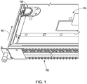
- FIG. 1 shows an exemplary housing 150.
- the housing 150 can have a lid 170 (shown in transparency) that can be slid onto the housing 150 in direction 50.
- the housing 150 can include a server, a switch device, or a storage device.
- a latching apparatus 100 can be attached to the lid 170, to secure the lid 170 to the housing 150.
- the latching apparatus 100 can be fixed to the lid 170 using removable connectors or fasteners, such as nuts and bolts, screws, or the like.
- the housing 150 can include a mating piece (not shown) that connects to the latching apparatus 100. This is discussed below in greater detail with respect to FIGs. 2 through 5 .
- the latching apparatus 100 Upon sliding the lid 170 onto the housing 150, the latching apparatus 100 will come in contact with the mating piece. This connection between the latching apparatus 100 and the mating piece of the housing 150 secures the lid 170 onto the housing 150.
- the latching apparatus 100 can be implemented on other system components, outside of a housing.
- FIG. 2 shows an exemplary latching apparatus 100 facilitating a connection between the lid 170 and the housing 150.
- the latching apparatus 100 can have a flexible component 105 and a rigid component 107.
- the flexible component 105 can be made from stainless steel, plastic, or any material configured to withstand varying increased temperatures and deform with applied pressure.
- the rigid component 107 can be made from sheet-metal, or cast iron with an electroless nickel coating. It should be understood that the rigid component 107 can be made from any material that is cost effective, and achieves high levels of hardness and corrosion resistance.
- the rigid component 107 can be configured to receive a securing element 201 of the housing 150.
- the securing element 201 can be a hook or a tab feature.
- the securing element 201 can be made from the same material as the rigid component 107 to ensure high levels of hardness and corrosion resistance. Furthermore, the rigidness of both components ensures a secured mating such that the latching apparatus 100 is able to withstand any shock or vibration testing.
- the rigid component 107 is discussed in greater detail below with respect to FIG. 3 .
- the rigid component 107 can have multiple features to ensure a secured connection to the housing 150 and the lid 170.
- the rigid component 107 can have a receiving element 121.
- the receiving element 121 can be an aperture configured to the dimensions of the securing element 201 of the housing 150 (shown in FIGs. 2 and 5 ).
- the receiving element 121 can be designed to receive the rectangular securing element 201.
- the receiving element 121 and the securing element 201 can be designed with minimal tolerance to ensure a secured connection between the latching apparatus 100 and the housing 150.
- the rigid component 107 can also include receiving elements 122. Each of the receiving elements 122 can be located on a tab 123 extending from the rigid component 107. Each of the receiving elements 122 can be configured to receive a screw to secure the rigid component 107 to the flexible component 105.
- the flexible component 105 can have a proximal end 106 and a distal end 104. The distal end 104 of the flexible component 105 can include mating tabs 112.
- the mating tabs 112 can each include apertures 113.
- the apertures 113 located on the flexible component 105 can be aligned with the receiving elements 122 of the rigid component 107, such that the two components are mated together using any connectors or fasteners, such as nuts and bolts, screws, or the like.
- the assembled latching apparatus 100 is shown in FIG. 4 .
- the proximal end 106 of the flexible component 105 can have a flange member 108.
- the flange member 108 can include at least one aperture 109.
- the aperture 109 can be configured to receive a screw to secure the latching apparatus 100 to the lid 170.
- the flange member 108 contains two equal sized apertures 109. Any number of apertures 109 can be implemented herein to secure the flange member 108 to the lid 170.
- the flange member 108 can be secured to the lid 170 using any connectors or fasteners, such as nuts and bolts, screws, or the like.
- the flexible component 105 can also include a pressing region 111 at the distal end 104.
- the pressing region 111 can include an impressed surface.
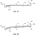
- FIG. 7A shows the latching apparatus 100 in the non-flexed position.
- the flexible component 105 can include a hinge.
- the hinge is indicated as an indention 110.
- the hinge can be any configuration of a solid flexible hinge that serves as a leverage point to disengage the latching apparatus 100 from the securing element of the housing (not shown), once the pressing region 111 is pressed.
- FIG. 7B shows the latching apparatus 100 in the flexed position.
- the fastening of the flange member 108 to the housing causes at least a portion of the flange member 108 to become parallel with the lid 170.
- the indention 110 causes the distal end 104 to be separated by a nominal space 5 from the lid 170. This nominal space 5 creates enough force to secure the securing element of the housing (not shown) within the receiving element 121 of the rigid component 107.
- the rigid component 107 can further include an attachment element 124 opposite of the receiving element 121.
- the attachment element 124 can include tab features 125.
- the tab features 125 can be configured to secure the rigid component 107 to mating features (not shown) of the housing 150.
- the attachment element 124 can be on a different plane than the tabs 123.
- the attachment element 124 can attach to a ridge element 202 of the housing 150.
- the pressing region 111 of the flexible component 105 drives the distal end 104 of the flexible component 105 towards the lid 170.
- the latching apparatus 100 need only contain an area configured to receive force to disengage or engage via the indention 110. Because the indention 110 serves as the leverage point of the latching apparatus only the indention 110 of the latching apparatus 100 is made from a flexible material. This is discussed in greater detail with respect to FIGs. 6A, 6B and 6C .
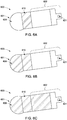
- FIGs. 6A, 6B, and 6C exemplify alternative embodiments of the latching apparatus and the various compositions.
- FIG. 6A illustrates a latching apparatus 600 with a distal end 601 and a proximal end 602.
- the distal end 601 can have a flange member 608 that is similar to the flange member 108 of FIG. 2 .
- the proximal end 602 can have a receiving element 621 that is similar to the receiving element 121 of FIG. 2 .
- the latching apparatus 600 can also have an indention 610 similar to the indention 110 of FIG. 2 .
- the indention 610 can be made up of flexible material, as described above with respect to FIG. 2 .
- the remaining body of the latching apparatus 600, including the flange member 608 and the proximal end 602 can be made from a rigid material, as described above with respect to FIG. 2 .
- FIG. 6B illustrates an exemplary embodiment where the indention 610 and the distal end 601 are made up of flexible material.
- the proximal end 602 can be made of a rigid material. This includes, for example, the receiving element 621.
- FIG. 6C illustrates an exemplary embodiment where the indention 610, the flange member 608, and a significant section of the proximal end 602 are made up of a flexible material. This configuration is described in detail above with respect to FIGs. 1 through 5 .
- the distal end 104 of the flexible component 105 is driven towards the lid 170 of the housing 150.
- the mating of the two surfaces creates enough space to cause a separation of the securing element 201 and the receiving element 121.
- the mating of the two surfaces also creates enough space to cause a separation of the ridge element 202 and the attachment element 124. This separation causes the latching apparatus 100 to be disengaged from the housing 150.
- the plasticity of the flexible component 105 allows for a simple compression of the pressing region 111 to release the latching apparatus 100, while the stiffness of the rigid component 107 ensures a secured mating between the latching apparatus 100 and the housing 150.
Landscapes
- Engineering & Computer Science (AREA)
- Microelectronics & Electronic Packaging (AREA)
- Computer Hardware Design (AREA)
- General Engineering & Computer Science (AREA)
- Casings For Electric Apparatus (AREA)
- Connection Of Plates (AREA)
- Clamps And Clips (AREA)
Abstract
Description
- The present disclosure generally relates to a latching apparatus that secures a lid to a housing.
- A typical data center has thousands of physical rack structures, each with vertically oriented slots or housing that may house multiple devices. Typical housed devices in a rack structure include servers, switches, and storage devices. Some data centers have tens of thousands of servers, attendant storage devices, and network switches.
- For operational convenience and flexibility, each server component is typically "hot plug" connected within the rack structure. This type of electrical connection permits any of the electronic components to be removed and re-installed within the support housing without disturbing the operation of the other server components. A typical latching apparatus is used to secure a server component within the rack structure. The typical latching apparatus is designed to be engaged and disengaged to remove and reinstall the electrical component within the support housing. Often, the typical latching apparatus is designed and cut from sheet-metal due to cost efficiencies. However, sheet metal is relatively thin and not structurally strong. Therefore, when the rack structure and its housed servers, attendant storage devices, and network switches undergo shock and vibration testing, the latching apparatuses tend to fail.
- In response, latching apparatuss have been designed with greater thickness than traditional sheet metal to withstand the shock and vibration testing. However, the increased thickness impacts the ease of the release component to engage and disengage the latching apparatus. The present disclosure provides an improved latching apparatus that will not accidentally disengage when undergoing shock and vibration testing, while still providing ease of use for engaging and disengaging when pressing the release component.
- The various examples of the present disclosure are directed towards a latching apparatus with a flexible component and a rigid component. The flexible component is made of a first material and includes a distal end, a proximal end, and an indention between the distal end the proximal end. The distal end includes a mating tab, whereas the proximal end includes a flange member for fixing the flexible component to a lid of a housing. The rigid component is made of a second material and is coupled to the mating tab. The rigid component includes a receiving element for engaging with a securing element of the housing. The latching apparatus includes a pressing region formed in either the flexible component or the rigid component. The pressing region can be located between the indention and the receiving element. The first material has a higher flexibility than the second material.
- In some embodiments, the flexible component can be made from aluminum, sheet-metal, plastic, or some combination thereof. In some examples, the rigid component and the securing element of the housing can be made from stainless steel, mild steel, cast iron with an electroless nickel coating, or some combination thereof. In some embodiments, the securing element of the housing can include a tab or hook feature. The rigid component can include a receiving element located on the mating tab. The receiving element can include aperture configured to receive a screw to secure the flexible component to the rigid component.
- In some embodiments, the flange member can be secured to the lid of the housing by way of removable connectors or fasteners, such as nuts and bolts, screws, or the like. In some embodiments, the rigid component can include an attachment element located on the opposite side of the mating tab and configured to engage with a ridge element of the housing. The pressing region can include an impressed surface.
- The above summary is not intended to represent each embodiment or every aspect of the present disclosure. Rather, the foregoing summary merely provides an example of some of the novel aspects and features set forth herein. The above features and advantages, and other features and advantages of the present disclosure, will be readily apparent from the following detailed description of representative embodiments and modes for carrying out the present invention, when taken in connection with the accompanying drawings and the appended claims.
- The accompanying drawings exemplify the embodiments of the present invention and, together with the description, serve to explain and illustrate principles of the invention. The drawings are intended to illustrate major features of the exemplary embodiments in a diagrammatic manner. The drawings are not intended to depict every feature of actual embodiments nor relative dimensions of the depicted elements, and are not drawn to scale.
-
FIG. 1 shows an exemplary system component and lid being inserted onto the system component, according to an embodiment of the present disclosure. -
FIG. 2 shows an exemplary latching apparatus securing the system component ofFIG. 1 , according to an embodiment of the present disclosure. -
FIG. 3 shows an exploded view of the latching apparatus and its components, according to an embodiment of the present disclosure. -
FIG. 4 shows an assembled view of the latching apparatus and its components, according to an embodiment of the present disclosure. -
FIG. 5 shows the latching apparatus securing the lid to the system component ofFIG. 1 , according to an embodiment of the present disclosure. -
FIG. 6A exemplifies alternative embodiments of the latching apparatus and the various compositions. -
FIG. 6B exemplifies alternative embodiments of the latching apparatus and the various compositions. -
FIG. 6C exemplifies alternative embodiments of the latching apparatus and the various compositions. -
FIG. 7A shows a side view of the latching apparatus and its components in the non-flexed position, according to an embodiment of the present disclosure. -
FIG. 7B shows a side view of the latching apparatus and its components in the flexed position, according to an embodiment of the present disclosure. - The present invention is described with reference to the attached figures, where like reference numerals are used throughout the figures to designate similar or equivalent elements. The figures are not drawn to scale and are provided merely to illustrate the instant invention. Several aspects of the invention are described below with reference to example applications for illustration. It should be understood that numerous specific details, relationships, and methods are set forth to provide a full understanding of the invention. One having ordinary skill in the relevant art, however, will readily recognize that the invention can be practiced without one or more of the specific details, or with other methods. In other instances, well-known structures or operations are not shown in detail to avoid obscuring the invention. The present invention is not limited by the illustrated ordering of acts or events, as some acts may occur in different orders and/or concurrently with other acts or events. Furthermore, not all illustrated acts or events are required to implement a methodology in accordance with the present invention.
- The present disclosure provides a latching apparatus with a flexible component and a rigid component. The flexible component is made of a first material and includes a distal end, a proximal end, and an indention between the distal end the proximal end. The distal end includes a mating tab, whereas the proximal end includes a flange member for fixing the flexible component to a lid of a housing. The rigid component is made of a second material and is coupled to the mating tab. The rigid component includes a receiving element for engaging with a securing element of the housing. The latching apparatus includes a pressing region formed in either the flexible component or the rigid component. The pressing region can be located between the indention and the receiving element. The first material has a higher flexibility than the second material.
-
FIG. 1 shows anexemplary housing 150. Thehousing 150 can have a lid 170 (shown in transparency) that can be slid onto thehousing 150 indirection 50. For exemplary purposes, thehousing 150 can include a server, a switch device, or a storage device. A latchingapparatus 100 can be attached to thelid 170, to secure thelid 170 to thehousing 150. In some embodiments, the latchingapparatus 100 can be fixed to thelid 170 using removable connectors or fasteners, such as nuts and bolts, screws, or the like. Thehousing 150 can include a mating piece (not shown) that connects to thelatching apparatus 100. This is discussed below in greater detail with respect toFIGs. 2 through 5 . Upon sliding thelid 170 onto thehousing 150, the latchingapparatus 100 will come in contact with the mating piece. This connection between the latchingapparatus 100 and the mating piece of thehousing 150 secures thelid 170 onto thehousing 150. A person of ordinary skill in the art would appreciate that the latchingapparatus 100 can be implemented on other system components, outside of a housing. -
FIG. 2 shows anexemplary latching apparatus 100 facilitating a connection between thelid 170 and thehousing 150. The latchingapparatus 100 can have aflexible component 105 and arigid component 107. In some embodiments, theflexible component 105 can be made from stainless steel, plastic, or any material configured to withstand varying increased temperatures and deform with applied pressure. Therigid component 107 can be made from sheet-metal, or cast iron with an electroless nickel coating. It should be understood that therigid component 107 can be made from any material that is cost effective, and achieves high levels of hardness and corrosion resistance. Therigid component 107 can be configured to receive a securingelement 201 of thehousing 150. The securingelement 201 can be a hook or a tab feature. The securingelement 201 can be made from the same material as therigid component 107 to ensure high levels of hardness and corrosion resistance. Furthermore, the rigidness of both components ensures a secured mating such that the latchingapparatus 100 is able to withstand any shock or vibration testing. Therigid component 107 is discussed in greater detail below with respect toFIG. 3 . - Referring momentarily to the exploded view of the
latching apparatus 100 inFIG. 3 , therigid component 107 can have multiple features to ensure a secured connection to thehousing 150 and thelid 170. Specifically, therigid component 107 can have a receivingelement 121. The receivingelement 121 can be an aperture configured to the dimensions of the securingelement 201 of the housing 150 (shown inFIGs. 2 and5 ). For example, where the securingelement 201 includes a rectangular shape, the receivingelement 121 can be designed to receive therectangular securing element 201. The receivingelement 121 and the securingelement 201 can be designed with minimal tolerance to ensure a secured connection between the latchingapparatus 100 and thehousing 150. - The
rigid component 107 can also include receivingelements 122. Each of the receivingelements 122 can be located on atab 123 extending from therigid component 107. Each of the receivingelements 122 can be configured to receive a screw to secure therigid component 107 to theflexible component 105. Theflexible component 105 can have aproximal end 106 and adistal end 104. Thedistal end 104 of theflexible component 105 can includemating tabs 112. Themating tabs 112 can each includeapertures 113. Theapertures 113 located on theflexible component 105 can be aligned with the receivingelements 122 of therigid component 107, such that the two components are mated together using any connectors or fasteners, such as nuts and bolts, screws, or the like. The assembledlatching apparatus 100 is shown inFIG. 4 . - Referring back to
FIG. 2 , theproximal end 106 of theflexible component 105 can have aflange member 108. Theflange member 108 can include at least oneaperture 109. Theaperture 109 can be configured to receive a screw to secure thelatching apparatus 100 to thelid 170. In some embodiment, theflange member 108 contains two equalsized apertures 109. Any number ofapertures 109 can be implemented herein to secure theflange member 108 to thelid 170. Furthermore, theflange member 108 can be secured to thelid 170 using any connectors or fasteners, such as nuts and bolts, screws, or the like. - Referring momentarily to the side views of the
latching apparatus 100 inFIGs. 7A and 7B , theflexible component 105 can also include apressing region 111 at thedistal end 104. Thepressing region 111 can include an impressed surface.FIG. 7A shows the latchingapparatus 100 in the non-flexed position. Theflexible component 105 can include a hinge. For the purposes of this example, the hinge is indicated as anindention 110. However, it should be understood that the hinge can be any configuration of a solid flexible hinge that serves as a leverage point to disengage thelatching apparatus 100 from the securing element of the housing (not shown), once thepressing region 111 is pressed.FIG. 7B shows the latchingapparatus 100 in the flexed position. In the flexed position, the fastening of theflange member 108 to the housing causes at least a portion of theflange member 108 to become parallel with thelid 170. As a result, theindention 110 causes thedistal end 104 to be separated by anominal space 5 from thelid 170. Thisnominal space 5 creates enough force to secure the securing element of the housing (not shown) within the receivingelement 121 of therigid component 107. - Referring momentarily to
FIG. 5 , therigid component 107 can further include anattachment element 124 opposite of the receivingelement 121. Theattachment element 124 can include tab features 125. The tab features 125 can be configured to secure therigid component 107 to mating features (not shown) of thehousing 150. Theattachment element 124 can be on a different plane than thetabs 123. Theattachment element 124 can attach to aridge element 202 of thehousing 150. - Referring back to
FIG. 2 , once thepressing region 111 of theflexible component 105 is pressed, it drives thedistal end 104 of theflexible component 105 towards thelid 170. It should be understood that the function of latchingapparatus 100 can be achieved without thepressing region 111. The latchingapparatus 100 need only contain an area configured to receive force to disengage or engage via theindention 110. Because theindention 110 serves as the leverage point of the latching apparatus only theindention 110 of thelatching apparatus 100 is made from a flexible material. This is discussed in greater detail with respect toFIGs. 6A, 6B and 6C . -
FIGs. 6A, 6B, and 6C exemplify alternative embodiments of the latching apparatus and the various compositions.FIG. 6A illustrates alatching apparatus 600 with adistal end 601 and aproximal end 602. Thedistal end 601 can have aflange member 608 that is similar to theflange member 108 ofFIG. 2 . Theproximal end 602 can have a receivingelement 621 that is similar to the receivingelement 121 ofFIG. 2 . The latchingapparatus 600 can also have anindention 610 similar to theindention 110 ofFIG. 2 . In thelatching apparatus 600, ofFIG. 6A , theindention 610 can be made up of flexible material, as described above with respect toFIG. 2 . The remaining body of thelatching apparatus 600, including theflange member 608 and theproximal end 602, can be made from a rigid material, as described above with respect toFIG. 2 . -
FIG. 6B illustrates an exemplary embodiment where theindention 610 and thedistal end 601 are made up of flexible material. Theproximal end 602 can be made of a rigid material. This includes, for example, the receivingelement 621. In contrast,FIG. 6C illustrates an exemplary embodiment where theindention 610, theflange member 608, and a significant section of theproximal end 602 are made up of a flexible material. This configuration is described in detail above with respect toFIGs. 1 through 5 . - Referring back to
FIG. 2 , once thepressing region 111 of theflexible component 105 is pressed, thedistal end 104 of theflexible component 105 is driven towards thelid 170 of thehousing 150. The mating of the two surfaces creates enough space to cause a separation of the securingelement 201 and the receivingelement 121. Referring momentarily toFIG. 5 , the mating of the two surfaces also creates enough space to cause a separation of theridge element 202 and theattachment element 124. This separation causes thelatching apparatus 100 to be disengaged from thehousing 150. The plasticity of theflexible component 105 allows for a simple compression of thepressing region 111 to release thelatching apparatus 100, while the stiffness of therigid component 107 ensures a secured mating between the latchingapparatus 100 and thehousing 150. - While various examples of the present invention have been described above, it should be understood that they have been presented by way of example only, and not limitation. Thus, the breadth and scope of the present invention should not be limited by any of the above described examples. Rather, the scope of the invention should be defined in accordance with the following claims and their equivalents.
- Although the invention has been illustrated and described with respect to one or more implementations, equivalent alterations, and modifications will occur to others skilled in the art upon the reading and understanding of this specification and the annexed drawings. In addition, while a particular feature of the invention may have been disclosed with respect to only one of several implementations, such feature may be combined with one or more other features of the other implementations as may be desired and advantageous for any given or particular application.
- The terminology used herein is for the purpose of describing particular examples only and is not intended to be limiting of the invention. As used herein, the singular forms "a," "an," and "the" are intended to include the plural forms as well, unless the context clearly indicates otherwise. Furthermore, to the extent that the terms "including," "includes," "having," "has," "with," or variants thereof, are used in either the detailed description and/or the claims, such terms are intended to be inclusive in a manner similar to the term "comprising."
- Unless otherwise defined, all terms (including technical and scientific terms) used herein have the same meaning as commonly understood by one of ordinary skill in the art to which this invention belongs. Furthermore, terms, such as those defined in commonly used dictionaries, should be interpreted as having a meaning that is consistent with their meaning in the context of the relevant art and will not be interpreted in an idealized or overly formal sense unless expressly so defined herein.
Claims (10)
- A latching apparatus (100), characterized by comprising:a flexible component (105) of a first material and comprising a distal end (104), a proximal end (106), and an indention (110) between the distal end (104) the proximal end (106), the distal end (104) comprising a mating tab (112), the proximal end (106) comprising a flange member (108) for fixing the flexible component (105) to a lid (170) of a housing (150);a rigid component (107) of a second material and coupled to the mating tab (112) and comprising a receiving element (121) for engaging with a securing element (201) of the housing (150); anda pressing region (111) formed in one of the flexible component (105) and the rigid component (107) between the indention (110) and the receiving element (121),wherein the first material has a higher flexibility that the second material.
- The latching apparatus (100) of anyone of previous claims, wherein the flexible component (105) comprises at least one of: aluminum, sheet-metal, plastic, and a combination thereof.
- The latching apparatus (100) of anyone of previous claims, wherein the rigid component (107) comprises at least one of: stainless steel, mild steel, cast iron with an electroless nickel coating, and a combination thereof.
- The latching apparatus (100) of anyone of previous claims, wherein the securing element (201) of the housing (150) comprises at least one of a tab feature and a hook feature.
- The latching apparatus (100) of anyone of previous claims, wherein the securing element (201) of the housing (150) comprises at least one of: stainless steel, mild steel, cast iron with an electroless nickel coating, and a combination thereof.
- The latching apparatus (100) of anyone of previous claims, wherein the rigid component (107) comprises a receiving element (122) located on the mating tab (112).
- The latching apparatus (100) of anyone of previous claims, wherein the receiving element (122) comprises aperture configured to receive a screw to secure the flexible component (105) to the rigid component (107).
- The latching apparatus (100) of anyone of previous claims, wherein the flange member (108) is secured to the lid (170) of the housing (150) via at least one of a nut, screw, connector, and fastener.
- The latching apparatus (100) of anyone of previous claims, wherein the rigid component (107) further includes an attachment element (124) opposite of the mating tab (112), and configured to engage with a ridge element (202) of the housing (150).
- The latching apparatus (100) of anyone of previous claims, wherein the pressing region (111) comprises an impressed surface.
Applications Claiming Priority (2)
| Application Number | Priority Date | Filing Date | Title |
|---|---|---|---|
| US201862703213P | 2018-07-25 | 2018-07-25 | |
| US16/285,989 US11700700B2 (en) | 2018-07-25 | 2019-02-26 | Composite latch cover |
Publications (2)
| Publication Number | Publication Date |
|---|---|
| EP3599803A1 true EP3599803A1 (en) | 2020-01-29 |
| EP3599803B1 EP3599803B1 (en) | 2022-03-02 |
Family
ID=66647156
Family Applications (1)
| Application Number | Title | Priority Date | Filing Date |
|---|---|---|---|
| EP19176265.7A Active EP3599803B1 (en) | 2018-07-25 | 2019-05-23 | Latching apparatus |
Country Status (5)
| Country | Link |
|---|---|
| US (1) | US11700700B2 (en) |
| EP (1) | EP3599803B1 (en) |
| JP (1) | JP6920372B2 (en) |
| CN (1) | CN110761633B (en) |
| TW (1) | TWI705752B (en) |
Families Citing this family (4)
| Publication number | Priority date | Publication date | Assignee | Title |
|---|---|---|---|---|
| US12119505B2 (en) | 2019-07-29 | 2024-10-15 | Brightz, ltd. | Multi-purpose battery pack |
| TWI705751B (en) * | 2019-10-16 | 2020-09-21 | 緯創資通股份有限公司 | Electronic device and housing structure and locking unit thereof |
| CN113685083B (en) * | 2020-05-19 | 2022-09-06 | 富联精密电子(天津)有限公司 | Locking device and server case with same |
| TWI868552B (en) * | 2022-12-30 | 2025-01-01 | 神雲科技股份有限公司 | Locking device |
Citations (2)
| Publication number | Priority date | Publication date | Assignee | Title |
|---|---|---|---|---|
| US1175603A (en) * | 1914-08-29 | 1916-03-14 | Peter Clausen | Device for closing, opening, and locking covers on boxes. |
| US20090102334A1 (en) * | 2007-10-22 | 2009-04-23 | Inventec Corporation | Case structure for server |
Family Cites Families (16)
| Publication number | Priority date | Publication date | Assignee | Title |
|---|---|---|---|---|
| US4268098A (en) * | 1979-09-04 | 1981-05-19 | Whirlpool Corporation | Retaining clip for removable cabinet for front-serviceable appliances |
| JP2000013046A (en) | 1998-06-25 | 2000-01-14 | Sony Corp | Disk media storage case |
| DE19935897A1 (en) * | 1999-07-30 | 2001-02-01 | Bosch Gmbh Robert | Housing part with a locking element arranged thereon |
| US6929338B2 (en) * | 2003-09-08 | 2005-08-16 | Inventec Corp. | Computer case |
| TWM245488U (en) * | 2003-11-14 | 2004-10-01 | Tatung Co | Structure for disassembling the upper lid of housing |
| US7735669B2 (en) * | 2006-02-22 | 2010-06-15 | Super Micro Computer Inc. | Modular case assembly device |
| CN2909354Y (en) * | 2006-03-14 | 2007-06-06 | 鸿富锦精密工业(深圳)有限公司 | Fixing structure of computer coverplate |
| CN101588692B (en) * | 2008-05-23 | 2012-06-13 | 深圳富泰宏精密工业有限公司 | Lock device |
| CN101931066A (en) * | 2009-06-26 | 2010-12-29 | 深圳富泰宏精密工业有限公司 | Fastening mechanism and portable electronic equipment using same |
| US20110185775A1 (en) * | 2010-02-01 | 2011-08-04 | Master Lock Company Llc | Padlocks with anti-rapping security features |
| TWI441013B (en) * | 2011-10-18 | 2014-06-11 | Hon Hai Prec Ind Co Ltd | Power supply unit |
| TWI479978B (en) * | 2012-04-20 | 2015-04-01 | Hon Hai Prec Ind Co Ltd | Electronic device |
| TWI489930B (en) * | 2012-08-28 | 2015-06-21 | 緯創資通股份有限公司 | Limit mechanism and related electronic device |
| CN105988529A (en) * | 2015-03-06 | 2016-10-05 | 鸿富锦精密工业(武汉)有限公司 | Shell of electronic device |
| US9681574B1 (en) * | 2016-08-18 | 2017-06-13 | Aic Inc. | Chassis self-unlock mechanism |
| US10349547B1 (en) * | 2018-05-29 | 2019-07-09 | Arris Enterprises Llc | Quick release chassis cover |
-
2019
- 2019-02-26 US US16/285,989 patent/US11700700B2/en active Active
- 2019-04-26 TW TW108114796A patent/TWI705752B/en active
- 2019-05-09 CN CN201910383226.7A patent/CN110761633B/en active Active
- 2019-05-23 EP EP19176265.7A patent/EP3599803B1/en active Active
- 2019-06-28 JP JP2019121267A patent/JP6920372B2/en active Active
Patent Citations (2)
| Publication number | Priority date | Publication date | Assignee | Title |
|---|---|---|---|---|
| US1175603A (en) * | 1914-08-29 | 1916-03-14 | Peter Clausen | Device for closing, opening, and locking covers on boxes. |
| US20090102334A1 (en) * | 2007-10-22 | 2009-04-23 | Inventec Corporation | Case structure for server |
Also Published As
| Publication number | Publication date |
|---|---|
| US11700700B2 (en) | 2023-07-11 |
| CN110761633A (en) | 2020-02-07 |
| JP6920372B2 (en) | 2021-08-18 |
| EP3599803B1 (en) | 2022-03-02 |
| CN110761633B (en) | 2021-10-26 |
| TWI705752B (en) | 2020-09-21 |
| US20200037457A1 (en) | 2020-01-30 |
| TW202007872A (en) | 2020-02-16 |
| JP2020016334A (en) | 2020-01-30 |
Similar Documents
| Publication | Publication Date | Title |
|---|---|---|
| EP3599803B1 (en) | Latching apparatus | |
| TWI771570B (en) | Apparatus for securing electronic component within server device and server device using same | |
| US6299460B1 (en) | Spring-loaded backing plate assembly for use with land grid array-type devices | |
| US8598462B2 (en) | Cable management apparatus | |
| US20120228002A1 (en) | Cable management apparatus | |
| US20100271768A1 (en) | Mounting apparatus for peripheral component interconnect card | |
| US20110193459A1 (en) | Device housing with latching mechanism | |
| US6513206B1 (en) | Retaining clip for panel mounted input/output connector | |
| US7881075B2 (en) | Apparatus and methods for mounting and retaining power monitoring systems | |
| US6535390B1 (en) | Securing device and electronic appliance assembly applying the same | |
| US20210373616A1 (en) | Expansion card assembly and expansion card cage | |
| TW201236548A (en) | Mounting apparatus for circuit card | |
| US5853297A (en) | System and method for co-planar and nearly co-planar printed circuit board extension docking system | |
| CN101847036B (en) | Computer case and unlocking structure thereof | |
| EP1220592A1 (en) | An apparatus and a method of providing a flexible electrical connection between two components | |
| US11015633B2 (en) | Snap fit fasteners | |
| US7555191B1 (en) | Self-locking unidirectional interposer springs for optical transceiver modules | |
| US20120152868A1 (en) | Cable management apparatus | |
| CN102301535A (en) | Screw support for fastening multiple screws | |
| US8328576B2 (en) | Cable connector assembly | |
| US4718861A (en) | Detachable cable strain relief clamp | |
| CN223728623U (en) | Base box structure and wall products | |
| US6176461B1 (en) | Enclosure apparatus with removable base | |
| US10505353B2 (en) | Terminal housings, covers, and plate apparatus | |
| US8605432B2 (en) | Portable electronic device |
Legal Events
| Date | Code | Title | Description |
|---|---|---|---|
| PUAI | Public reference made under article 153(3) epc to a published international application that has entered the european phase |
Free format text: ORIGINAL CODE: 0009012 |
|
| STAA | Information on the status of an ep patent application or granted ep patent |
Free format text: STATUS: THE APPLICATION HAS BEEN PUBLISHED |
|
| AK | Designated contracting states |
Kind code of ref document: A1 Designated state(s): AL AT BE BG CH CY CZ DE DK EE ES FI FR GB GR HR HU IE IS IT LI LT LU LV MC MK MT NL NO PL PT RO RS SE SI SK SM TR |
|
| AX | Request for extension of the european patent |
Extension state: BA ME |
|
| STAA | Information on the status of an ep patent application or granted ep patent |
Free format text: STATUS: REQUEST FOR EXAMINATION WAS MADE |
|
| 17P | Request for examination filed |
Effective date: 20200526 |
|
| RBV | Designated contracting states (corrected) |
Designated state(s): AL AT BE BG CH CY CZ DE DK EE ES FI FR GB GR HR HU IE IS IT LI LT LU LV MC MK MT NL NO PL PT RO RS SE SI SK SM TR |
|
| GRAP | Despatch of communication of intention to grant a patent |
Free format text: ORIGINAL CODE: EPIDOSNIGR1 |
|
| STAA | Information on the status of an ep patent application or granted ep patent |
Free format text: STATUS: GRANT OF PATENT IS INTENDED |
|
| INTG | Intention to grant announced |
Effective date: 20211028 |
|
| GRAS | Grant fee paid |
Free format text: ORIGINAL CODE: EPIDOSNIGR3 |
|
| GRAA | (expected) grant |
Free format text: ORIGINAL CODE: 0009210 |
|
| STAA | Information on the status of an ep patent application or granted ep patent |
Free format text: STATUS: THE PATENT HAS BEEN GRANTED |
|
| AK | Designated contracting states |
Kind code of ref document: B1 Designated state(s): AL AT BE BG CH CY CZ DE DK EE ES FI FR GB GR HR HU IE IS IT LI LT LU LV MC MK MT NL NO PL PT RO RS SE SI SK SM TR |
|
| REG | Reference to a national code |
Ref country code: GB Ref legal event code: FG4D |
|
| REG | Reference to a national code |
Ref country code: CH Ref legal event code: EP Ref country code: AT Ref legal event code: REF Ref document number: 1473355 Country of ref document: AT Kind code of ref document: T Effective date: 20220315 |
|
| REG | Reference to a national code |
Ref country code: DE Ref legal event code: R096 Ref document number: 602019012013 Country of ref document: DE |
|
| REG | Reference to a national code |
Ref country code: IE Ref legal event code: FG4D |
|
| REG | Reference to a national code |
Ref country code: LT Ref legal event code: MG9D |
|
| REG | Reference to a national code |
Ref country code: NL Ref legal event code: MP Effective date: 20220302 |
|
| PG25 | Lapsed in a contracting state [announced via postgrant information from national office to epo] |
Ref country code: SE Free format text: LAPSE BECAUSE OF FAILURE TO SUBMIT A TRANSLATION OF THE DESCRIPTION OR TO PAY THE FEE WITHIN THE PRESCRIBED TIME-LIMIT Effective date: 20220302 Ref country code: RS Free format text: LAPSE BECAUSE OF FAILURE TO SUBMIT A TRANSLATION OF THE DESCRIPTION OR TO PAY THE FEE WITHIN THE PRESCRIBED TIME-LIMIT Effective date: 20220302 Ref country code: NO Free format text: LAPSE BECAUSE OF FAILURE TO SUBMIT A TRANSLATION OF THE DESCRIPTION OR TO PAY THE FEE WITHIN THE PRESCRIBED TIME-LIMIT Effective date: 20220602 Ref country code: LT Free format text: LAPSE BECAUSE OF FAILURE TO SUBMIT A TRANSLATION OF THE DESCRIPTION OR TO PAY THE FEE WITHIN THE PRESCRIBED TIME-LIMIT Effective date: 20220302 Ref country code: HR Free format text: LAPSE BECAUSE OF FAILURE TO SUBMIT A TRANSLATION OF THE DESCRIPTION OR TO PAY THE FEE WITHIN THE PRESCRIBED TIME-LIMIT Effective date: 20220302 Ref country code: ES Free format text: LAPSE BECAUSE OF FAILURE TO SUBMIT A TRANSLATION OF THE DESCRIPTION OR TO PAY THE FEE WITHIN THE PRESCRIBED TIME-LIMIT Effective date: 20220302 Ref country code: BG Free format text: LAPSE BECAUSE OF FAILURE TO SUBMIT A TRANSLATION OF THE DESCRIPTION OR TO PAY THE FEE WITHIN THE PRESCRIBED TIME-LIMIT Effective date: 20220602 |
|
| REG | Reference to a national code |
Ref country code: AT Ref legal event code: MK05 Ref document number: 1473355 Country of ref document: AT Kind code of ref document: T Effective date: 20220302 |
|
| PG25 | Lapsed in a contracting state [announced via postgrant information from national office to epo] |
Ref country code: PL Free format text: LAPSE BECAUSE OF FAILURE TO SUBMIT A TRANSLATION OF THE DESCRIPTION OR TO PAY THE FEE WITHIN THE PRESCRIBED TIME-LIMIT Effective date: 20220302 Ref country code: LV Free format text: LAPSE BECAUSE OF FAILURE TO SUBMIT A TRANSLATION OF THE DESCRIPTION OR TO PAY THE FEE WITHIN THE PRESCRIBED TIME-LIMIT Effective date: 20220302 Ref country code: GR Free format text: LAPSE BECAUSE OF FAILURE TO SUBMIT A TRANSLATION OF THE DESCRIPTION OR TO PAY THE FEE WITHIN THE PRESCRIBED TIME-LIMIT Effective date: 20220603 Ref country code: FI Free format text: LAPSE BECAUSE OF FAILURE TO SUBMIT A TRANSLATION OF THE DESCRIPTION OR TO PAY THE FEE WITHIN THE PRESCRIBED TIME-LIMIT Effective date: 20220302 |
|
| PG25 | Lapsed in a contracting state [announced via postgrant information from national office to epo] |
Ref country code: NL Free format text: LAPSE BECAUSE OF FAILURE TO SUBMIT A TRANSLATION OF THE DESCRIPTION OR TO PAY THE FEE WITHIN THE PRESCRIBED TIME-LIMIT Effective date: 20220302 |
|
| PG25 | Lapsed in a contracting state [announced via postgrant information from national office to epo] |
Ref country code: SM Free format text: LAPSE BECAUSE OF FAILURE TO SUBMIT A TRANSLATION OF THE DESCRIPTION OR TO PAY THE FEE WITHIN THE PRESCRIBED TIME-LIMIT Effective date: 20220302 Ref country code: SK Free format text: LAPSE BECAUSE OF FAILURE TO SUBMIT A TRANSLATION OF THE DESCRIPTION OR TO PAY THE FEE WITHIN THE PRESCRIBED TIME-LIMIT Effective date: 20220302 Ref country code: RO Free format text: LAPSE BECAUSE OF FAILURE TO SUBMIT A TRANSLATION OF THE DESCRIPTION OR TO PAY THE FEE WITHIN THE PRESCRIBED TIME-LIMIT Effective date: 20220302 Ref country code: PT Free format text: LAPSE BECAUSE OF FAILURE TO SUBMIT A TRANSLATION OF THE DESCRIPTION OR TO PAY THE FEE WITHIN THE PRESCRIBED TIME-LIMIT Effective date: 20220704 Ref country code: EE Free format text: LAPSE BECAUSE OF FAILURE TO SUBMIT A TRANSLATION OF THE DESCRIPTION OR TO PAY THE FEE WITHIN THE PRESCRIBED TIME-LIMIT Effective date: 20220302 Ref country code: CZ Free format text: LAPSE BECAUSE OF FAILURE TO SUBMIT A TRANSLATION OF THE DESCRIPTION OR TO PAY THE FEE WITHIN THE PRESCRIBED TIME-LIMIT Effective date: 20220302 Ref country code: AT Free format text: LAPSE BECAUSE OF FAILURE TO SUBMIT A TRANSLATION OF THE DESCRIPTION OR TO PAY THE FEE WITHIN THE PRESCRIBED TIME-LIMIT Effective date: 20220302 |
|
| PG25 | Lapsed in a contracting state [announced via postgrant information from national office to epo] |
Ref country code: IS Free format text: LAPSE BECAUSE OF FAILURE TO SUBMIT A TRANSLATION OF THE DESCRIPTION OR TO PAY THE FEE WITHIN THE PRESCRIBED TIME-LIMIT Effective date: 20220702 Ref country code: AL Free format text: LAPSE BECAUSE OF FAILURE TO SUBMIT A TRANSLATION OF THE DESCRIPTION OR TO PAY THE FEE WITHIN THE PRESCRIBED TIME-LIMIT Effective date: 20220302 |
|
| REG | Reference to a national code |
Ref country code: DE Ref legal event code: R097 Ref document number: 602019012013 Country of ref document: DE |
|
| REG | Reference to a national code |
Ref country code: CH Ref legal event code: PL |
|
| PLBE | No opposition filed within time limit |
Free format text: ORIGINAL CODE: 0009261 |
|
| STAA | Information on the status of an ep patent application or granted ep patent |
Free format text: STATUS: NO OPPOSITION FILED WITHIN TIME LIMIT |
|
| REG | Reference to a national code |
Ref country code: BE Ref legal event code: MM Effective date: 20220531 |
|
| PG25 | Lapsed in a contracting state [announced via postgrant information from national office to epo] |
Ref country code: MC Free format text: LAPSE BECAUSE OF FAILURE TO SUBMIT A TRANSLATION OF THE DESCRIPTION OR TO PAY THE FEE WITHIN THE PRESCRIBED TIME-LIMIT Effective date: 20220302 Ref country code: LU Free format text: LAPSE BECAUSE OF NON-PAYMENT OF DUE FEES Effective date: 20220523 Ref country code: LI Free format text: LAPSE BECAUSE OF NON-PAYMENT OF DUE FEES Effective date: 20220531 Ref country code: DK Free format text: LAPSE BECAUSE OF FAILURE TO SUBMIT A TRANSLATION OF THE DESCRIPTION OR TO PAY THE FEE WITHIN THE PRESCRIBED TIME-LIMIT Effective date: 20220302 Ref country code: CH Free format text: LAPSE BECAUSE OF NON-PAYMENT OF DUE FEES Effective date: 20220531 |
|
| 26N | No opposition filed |
Effective date: 20221205 |
|
| PG25 | Lapsed in a contracting state [announced via postgrant information from national office to epo] |
Ref country code: SI Free format text: LAPSE BECAUSE OF FAILURE TO SUBMIT A TRANSLATION OF THE DESCRIPTION OR TO PAY THE FEE WITHIN THE PRESCRIBED TIME-LIMIT Effective date: 20220302 |
|
| PG25 | Lapsed in a contracting state [announced via postgrant information from national office to epo] |
Ref country code: IE Free format text: LAPSE BECAUSE OF NON-PAYMENT OF DUE FEES Effective date: 20220523 |
|
| PG25 | Lapsed in a contracting state [announced via postgrant information from national office to epo] |
Ref country code: BE Free format text: LAPSE BECAUSE OF NON-PAYMENT OF DUE FEES Effective date: 20220531 |
|
| PG25 | Lapsed in a contracting state [announced via postgrant information from national office to epo] |
Ref country code: IT Free format text: LAPSE BECAUSE OF FAILURE TO SUBMIT A TRANSLATION OF THE DESCRIPTION OR TO PAY THE FEE WITHIN THE PRESCRIBED TIME-LIMIT Effective date: 20220302 |
|
| PG25 | Lapsed in a contracting state [announced via postgrant information from national office to epo] |
Ref country code: MK Free format text: LAPSE BECAUSE OF FAILURE TO SUBMIT A TRANSLATION OF THE DESCRIPTION OR TO PAY THE FEE WITHIN THE PRESCRIBED TIME-LIMIT Effective date: 20220302 Ref country code: CY Free format text: LAPSE BECAUSE OF FAILURE TO SUBMIT A TRANSLATION OF THE DESCRIPTION OR TO PAY THE FEE WITHIN THE PRESCRIBED TIME-LIMIT Effective date: 20220302 |
|
| PG25 | Lapsed in a contracting state [announced via postgrant information from national office to epo] |
Ref country code: HU Free format text: LAPSE BECAUSE OF FAILURE TO SUBMIT A TRANSLATION OF THE DESCRIPTION OR TO PAY THE FEE WITHIN THE PRESCRIBED TIME-LIMIT; INVALID AB INITIO Effective date: 20190523 |
|
| PG25 | Lapsed in a contracting state [announced via postgrant information from national office to epo] |
Ref country code: MT Free format text: LAPSE BECAUSE OF FAILURE TO SUBMIT A TRANSLATION OF THE DESCRIPTION OR TO PAY THE FEE WITHIN THE PRESCRIBED TIME-LIMIT Effective date: 20220302 |
|
| PGFP | Annual fee paid to national office [announced via postgrant information from national office to epo] |
Ref country code: DE Payment date: 20250325 Year of fee payment: 7 |
|
| PGFP | Annual fee paid to national office [announced via postgrant information from national office to epo] |
Ref country code: FR Payment date: 20250401 Year of fee payment: 7 |
|
| PG25 | Lapsed in a contracting state [announced via postgrant information from national office to epo] |
Ref country code: TR Free format text: LAPSE BECAUSE OF FAILURE TO SUBMIT A TRANSLATION OF THE DESCRIPTION OR TO PAY THE FEE WITHIN THE PRESCRIBED TIME-LIMIT Effective date: 20220302 |
|
| PGFP | Annual fee paid to national office [announced via postgrant information from national office to epo] |
Ref country code: GB Payment date: 20260325 Year of fee payment: 8 |