EP3599704B1 - Stator assembly - Google Patents
Stator assembly Download PDFInfo
- Publication number
- EP3599704B1 EP3599704B1 EP19187356.1A EP19187356A EP3599704B1 EP 3599704 B1 EP3599704 B1 EP 3599704B1 EP 19187356 A EP19187356 A EP 19187356A EP 3599704 B1 EP3599704 B1 EP 3599704B1
- Authority
- EP
- European Patent Office
- Prior art keywords
- stator
- windings
- pmg
- stator assembly
- conductive windings
- Prior art date
- Legal status (The legal status is an assumption and is not a legal conclusion. Google has not performed a legal analysis and makes no representation as to the accuracy of the status listed.)
- Active
Links
- 238000004804 winding Methods 0.000 claims description 114
- 239000004020 conductor Substances 0.000 claims description 4
- 230000001360 synchronised effect Effects 0.000 claims description 4
- 239000012777 electrically insulating material Substances 0.000 claims description 2
- 238000010586 diagram Methods 0.000 description 15
- 239000013598 vector Substances 0.000 description 15
- 238000001816 cooling Methods 0.000 description 9
- 239000012811 non-conductive material Substances 0.000 description 5
- 239000000696 magnetic material Substances 0.000 description 4
- 230000008901 benefit Effects 0.000 description 3
- 238000009413 insulation Methods 0.000 description 3
- 239000002826 coolant Substances 0.000 description 2
- 238000009826 distribution Methods 0.000 description 2
- 239000012530 fluid Substances 0.000 description 2
- 230000003993 interaction Effects 0.000 description 2
- 239000007788 liquid Substances 0.000 description 2
- 230000033001 locomotion Effects 0.000 description 2
- 238000007885 magnetic separation Methods 0.000 description 2
- 238000004519 manufacturing process Methods 0.000 description 2
- 238000000034 method Methods 0.000 description 2
- 238000000926 separation method Methods 0.000 description 2
- 230000000712 assembly Effects 0.000 description 1
- 238000000429 assembly Methods 0.000 description 1
- 230000005540 biological transmission Effects 0.000 description 1
- 230000008859 change Effects 0.000 description 1
- 239000012809 cooling fluid Substances 0.000 description 1
- 230000008878 coupling Effects 0.000 description 1
- 238000010168 coupling process Methods 0.000 description 1
- 238000005859 coupling reaction Methods 0.000 description 1
- 230000006870 function Effects 0.000 description 1
- 229910000078 germane Inorganic materials 0.000 description 1
- 230000006872 improvement Effects 0.000 description 1
- 229910001026 inconel Inorganic materials 0.000 description 1
- 230000010354 integration Effects 0.000 description 1
- 238000005461 lubrication Methods 0.000 description 1
- 230000014759 maintenance of location Effects 0.000 description 1
- 239000000463 material Substances 0.000 description 1
- 230000005226 mechanical processes and functions Effects 0.000 description 1
- 230000009467 reduction Effects 0.000 description 1
- 239000007858 starting material Substances 0.000 description 1
- 230000003245 working effect Effects 0.000 description 1
Images


Classifications
-
- H—ELECTRICITY
- H02—GENERATION; CONVERSION OR DISTRIBUTION OF ELECTRIC POWER
- H02K—DYNAMO-ELECTRIC MACHINES
- H02K1/00—Details of the magnetic circuit
- H02K1/06—Details of the magnetic circuit characterised by the shape, form or construction
- H02K1/12—Stationary parts of the magnetic circuit
- H02K1/16—Stator cores with slots for windings
- H02K1/165—Shape, form or location of the slots
-
- H—ELECTRICITY
- H02—GENERATION; CONVERSION OR DISTRIBUTION OF ELECTRIC POWER
- H02K—DYNAMO-ELECTRIC MACHINES
- H02K3/00—Details of windings
- H02K3/04—Windings characterised by the conductor shape, form or construction, e.g. with bar conductors
- H02K3/28—Layout of windings or of connections between windings
-
- H—ELECTRICITY
- H02—GENERATION; CONVERSION OR DISTRIBUTION OF ELECTRIC POWER
- H02K—DYNAMO-ELECTRIC MACHINES
- H02K1/00—Details of the magnetic circuit
- H02K1/06—Details of the magnetic circuit characterised by the shape, form or construction
- H02K1/12—Stationary parts of the magnetic circuit
- H02K1/17—Stator cores with permanent magnets
-
- H—ELECTRICITY
- H02—GENERATION; CONVERSION OR DISTRIBUTION OF ELECTRIC POWER
- H02K—DYNAMO-ELECTRIC MACHINES
- H02K16/00—Machines with more than one rotor or stator
-
- H—ELECTRICITY
- H02—GENERATION; CONVERSION OR DISTRIBUTION OF ELECTRIC POWER
- H02K—DYNAMO-ELECTRIC MACHINES
- H02K19/00—Synchronous motors or generators
- H02K19/16—Synchronous generators
- H02K19/38—Structural association of synchronous generators with exciting machines
-
- H—ELECTRICITY
- H02—GENERATION; CONVERSION OR DISTRIBUTION OF ELECTRIC POWER
- H02K—DYNAMO-ELECTRIC MACHINES
- H02K21/00—Synchronous motors having permanent magnets; Synchronous generators having permanent magnets
- H02K21/12—Synchronous motors having permanent magnets; Synchronous generators having permanent magnets with stationary armatures and rotating magnets
- H02K21/14—Synchronous motors having permanent magnets; Synchronous generators having permanent magnets with stationary armatures and rotating magnets with magnets rotating within the armatures
-
- H—ELECTRICITY
- H02—GENERATION; CONVERSION OR DISTRIBUTION OF ELECTRIC POWER
- H02K—DYNAMO-ELECTRIC MACHINES
- H02K21/00—Synchronous motors having permanent magnets; Synchronous generators having permanent magnets
- H02K21/48—Generators with two or more outputs
-
- H—ELECTRICITY
- H02—GENERATION; CONVERSION OR DISTRIBUTION OF ELECTRIC POWER
- H02K—DYNAMO-ELECTRIC MACHINES
- H02K3/00—Details of windings
- H02K3/04—Windings characterised by the conductor shape, form or construction, e.g. with bar conductors
- H02K3/12—Windings characterised by the conductor shape, form or construction, e.g. with bar conductors arranged in slots
-
- H—ELECTRICITY
- H02—GENERATION; CONVERSION OR DISTRIBUTION OF ELECTRIC POWER
- H02K—DYNAMO-ELECTRIC MACHINES
- H02K3/00—Details of windings
- H02K3/46—Fastening of windings on the stator or rotor structure
- H02K3/48—Fastening of windings on the stator or rotor structure in slots
- H02K3/487—Slot-closing devices
- H02K3/493—Slot-closing devices magnetic
-
- H—ELECTRICITY
- H02—GENERATION; CONVERSION OR DISTRIBUTION OF ELECTRIC POWER
- H02K—DYNAMO-ELECTRIC MACHINES
- H02K7/00—Arrangements for handling mechanical energy structurally associated with dynamo-electric machines, e.g. structural association with mechanical driving motors or auxiliary dynamo-electric machines
- H02K7/20—Structural association with auxiliary dynamo-electric machines, e.g. with electric starter motors or exciters
-
- H—ELECTRICITY
- H02—GENERATION; CONVERSION OR DISTRIBUTION OF ELECTRIC POWER
- H02K—DYNAMO-ELECTRIC MACHINES
- H02K16/00—Machines with more than one rotor or stator
- H02K16/04—Machines with one rotor and two stators
-
- H—ELECTRICITY
- H02—GENERATION; CONVERSION OR DISTRIBUTION OF ELECTRIC POWER
- H02K—DYNAMO-ELECTRIC MACHINES
- H02K2213/00—Specific aspects, not otherwise provided for and not covered by codes H02K2201/00 - H02K2211/00
- H02K2213/06—Machines characterised by the presence of fail safe, back up, redundant or other similar emergency arrangements
Definitions
- An aircraft main electric generator includes a main generator, exciter, and a permanent magnet generator (PMG).
- the PMG is used to power the stator of the exciter.
- additional PMGs can be utilized to power the on board aircraft flight computers.
- each such PMG is in its own mechanical package and separate from the main electric generator in order to achieve the desired fault tolerance and redundancy for human carry aircraft. The separation adds weight and occupy space in the aircraft.
- US4550267A discloses an electromotive machine having a stator provided with multiple sets of windings, each independently, electrically coupled to an electrical means, to establish separate power channels between the windings and the electrical means that allow for the simultaneous independent transmission of power through the channels when the machine is in operation.
- ES2325844A1 discloses an electric drive system for coupling a generator of a wind turbine to a network.
- the present disclosure relates to a stator assembly, including a cylindrical stator core, a circumferentially spaced set of posts extending from the stator core and defining a set of stator slots between adjacent posts, a first set of conductive windings wound about a first subset of stator slots in a first continuous circumferential portion of the stator core, and a second set of conductive windings wound about a second subset of stator slots in a second continuous circumferential portion of the stator core, and wherein the second continuous circumferential portion is different from the first continuous circumferential portion.
- the first continuous circumferential portion of the stator core is circumferentially spaced from the second circumferential portion of the stator core by at least one adjacent slot.
- the at least one adjacent slot is one of at least one empty adjacent slot or at least one adjacent slot having a non-conductive material within the slot.
- aspects of the disclosure can be implemented in any environment, apparatus, or method for arranging, maintaining, configuring, manufacturing, or operating a permanent magnet generator (PMG) assembly, for example, in a generator, a motor, or the like.
- PMG permanent magnet generator
- axial refers to a dimension along a longitudinal axis of the generator or along a longitudinal axis of a component disposed within the generator, such as a rotor.
- radial refers to a dimension extending between a center longitudinal axis of the generator, an outer circumference, or a circular or annular component disposed within the generator.
- proximal refers to a component being relatively closer to a referential element as compared to another component.
- forward used in conjunction with “axial” or “axially” refers to moving in a first direction toward a "front” of a component
- aft used in conjunction with “axial” or “axially” refers to an opposite direction toward the "rear” of a component
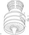
- FIG. 1 illustrates a gas turbine engine 10 having an accessory gear box (AGB) 12 and a generator 14 according to one aspect of the disclosure.
- the AGB 12 can be mechanically coupled to a turbine shaft (not shown) of the gas turbine engine 10 by way of a mechanical power take off 16.
- the gas turbine engine 10 can be any suitable gas turbine engine used in modern commercial and military aviation or it could be a variety of other known gas turbine engines such as a turboprop or turboshaft.
- the type and specifics of the gas turbine engine 10 are not germane to the disclosure and will not be described further herein.
- FIG. 2 more clearly illustrates a non-limiting example of the generator 14 and its housing 18, which can include a clamping interface 20, used to clamp the generator 14 to the AGB 12.
- Multiple electrical connections can be provided on the exterior of the generator 14 to provide for the transfer of electrical power to and from the generator 14.
- the electrical connections can be connected by cables to an electrical power distribution node of an aircraft having the gas turbine engine 10 to power various items on the aircraft, such as lights and seat-back monitors.
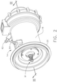
- FIG. 3 is a sectional view of the generator 14 of FIG. 2 .
- a rotatable shaft 40 is located within the generator 14 and is the primary structure for supporting a variety of components.
- the diameter of the rotatable shaft 40 can be fixed or vary along the length of the rotatable shaft 40.
- the rotatable shaft 40 is supported by spaced bearings 42 and 44.
- Several of the components of the generator 14 have a fixed component and a rotating component, with the rotating component being provided on the rotatable shaft 40.
- Examples of these components can include a main machine 50, an exciter 60, and a PMG assembly 70, with the corresponding rotating component comprising a main machine rotor 52, an exciter rotor 62, and a PMG rotor assembly 72, respectively, and the corresponding fixed component comprising a main machine stator 54, an exciter stator 64, and a PMG stator assembly 74.
- the main machine rotor 52, exciter rotor 62, and PMG rotor assembly 72 can include the rotatable shaft 40.
- the fixed components can be mounted to any suitable part of the housing 18.
- Each of the main machine stator 54, exciter stator 64, and PMG stator assembly 74 defines an interior through which the rotatable shaft 40 extends.
- each of the main machine rotor 52, exciter rotor 62, and PMG rotor assembly 72 can have multiple rotor poles and that each of the main machine stator 54, exciter stator 64, and PMG stator assembly 74 can have multiple stator poles such that magnetic fields can be produced by respective components.
- the generator 14 can, in turn, operably generate electrical power by way of rotation of the rotatable shaft 40 relative to the fixed components through the interaction of the magnetic fields and current-carrying conductors located in the rotating or fixed components.
- at least one rotor pole and stator pole can be formed by a core with a post and wire wound about the post to form a winding or set of windings, with the set of windings having at least one end turn
- the main machine stator 54 includes a stator core 89 having at least one post.
- a set of stator windings 90 are formed when a conductor or conductive wire is wound about the post or core 89.
- the set of windings 90 can also include a winding segment that extends across either the front or rear of the post core 89, forming at least one end turn 92.
- the rotatable rotor 40 is mechanically powered, driven, or rotated by a force, such as the mechanical energy of the engine 10, about an axis of rotation 41.
- the relative rotational motion of the rotatable rotor 40 and co-rotating components, including at least the main machine rotor 52, relative to the fixed or stationary stator components, including at least the main machine stator 54, generates electrical power in the set of stator windings 90 due to the interaction of the generator 14 magnetic fields.
- the electrical power generated in the set of stator windings 90 can be conductively connected to, and further delivered to, at least one electrical load.
- the generator 14 can provide the electrical power to a power distribution system or power distributed network.
- Non-limiting aspects of the generator 14 can be any combination of known generators.
- the main machine 50 can be either a synchronous or asynchronous generator.
- additional component, devices, or the like can be included to provide secondary generator 14 operations or functions.
- the generator 14 can include electromechanical accessories, or other accessories driven from the rotation of the rotatable shaft 40, including but not limited to, an oil pump, a fluid compressor, a hydraulic pump, or the like.
- the generator 14 can further include oil cooling or an oil cooling system for controlling the supply of oil to the oil cooling system.
- the cooling oil can be used to dissipate heat generated by the electrical and mechanical functions of the generator 14.
- the oil system can also provide for lubrication of the generator 14.
- the cooling system 80 can further include, for example, a cooling fluid reservoir and various cooling passages.
- the rotatable shaft 40 can provide one or more flow channels or paths for the main machine rotor 52, exciter rotor 62, and PMG rotor 72.
- the cooling system 80 can receive a flow of cooling oil (shown as arrow 85) by way of a first port (e.g. 84 or 82) which can be provide via a generator interior 51 or coolant reservoir 86, to the rotatable shaft 40, to a shaft outlet port 91.
- the PMG assembly 70 is used to power the stator 64 of the exciter 60.
- other PMG assemblies 70 used to power the on-board aircraft flight computers.
- each such PMG is in its own mechanical package and separate from the main electric generator in order to achieve the desired fault tolerance and redundancy for human carry aircraft. The separation adds weight and occupy space in the aircraft.
- FIG. 4 illustrates a schematic axial-facing view of the PMG assembly 70.
- the PMG rotor assembly 72 is coaxially received within a PMG stator assembly 74.
- the PMG rotor assembly 72 can include a circumferentially-spaced set of similarly or commonly-oriented permanent magnets 130 fixedly arranged at the outer radius of the PMG rotor assembly 72, and spaced from one another by non-magnet spacing elements 134.
- the PMG rotor assembly 72 can include a core 71 comprising a non-magnetic material, for example, for weight-saving or weight-reducing purposes.
- the PMG stator assembly 74 includes a number of inwardly facing (relative to the axis of rotation 41) and circumferentially spaced set of posts 73 separating slots 75 between the set of posts 73. At least a subset of slots 75 can be wound with a set of conductive windings 77, as described herein. At least a different subset of slots 106 can be left empty, or for example, filled with non-conductive materials.
- the PMG stator assembly 74 in the current disclosure can include three different sets of PMG stator windings, shown as a first set of PMG stator windings 100, a second set of PMG stator windings 120, and a third set of PMG stator windings 110.
- Each respective set of PMG stator windings 100, 110, 120 can be wound about a limited continuous circumferential portion of the PMG stator assembly 74, a limited continuous (e.g. continuously adjacent) subset of slots 75, or between a limited continuous (e.g. continuously adjacent) subset of posts 73.
- the first set of PMG stator windings 100 are wound about a limited continuous circumferential first portion 102 of the PMG stator assembly 74
- the second set of PMG stator windings 120 are wound about a limited continuous circumferential first portion 122 of the PMG stator assembly 74
- the third set of PMG stator windings 110 are wound about a limited continuous circumferential first portion 112 of the PMG stator assembly 74.
- the PMG rotor assembly 72 can include a retaining ring, shown for example as an Inconel retention ring 132, to ensure the fixing of the magnets 130 relative to the PMG rotor assembly 72.
- Each of the first, second, and third PMG stator windings 100, 110, 120 can be spaced by a different a limited continuous (e.g. continuously adjacent) subset of slots 75, or between a limited continuous (e.g. continuously adjacent) subset of posts 73.
- each set of PMG stator windings 100, 110, 120 are spaced from one another by a limited continuous circumferential portion 104 of empty or non-conductive materials slot 106. In this sense, each of the set of PMG stator windings 100, 110, 120 are both mechanically isolated from each other (e.g.
- the first set of PMG stator windings 100 are mechanically spaced from the second set of PMG stator windings 120 by at least the empty or non-conductive material slots 106), as well as magnetically isolated from each other (e.g. the circumferential first portion 102 is circumferentially spaced from the circumferential second portion 122).
- a failure of one of the PMG power outputs e.g. the power output of the first set of PMG stator windings 100
- another PMG power output e.g. the power output of either the second or third set of PMG stator windings 120, 110).
- FIG. 4 Also illustrated in FIG. 4 is a winding diagram 140 illustrating one non-limiting example of the sets of stator windings 100, 110, 120 of the illustrated PMG stator assembly 70.
- the winding diagram 140 is arranged by numbering the slots 144 in a horizontal arrangement, and illustrating the respective phase windings of each respective set of PMG stator windings 100, 110, 120.
- a "filled" slot 148 includes an arrow indicating a winding pattern, while an "unfilled,” “empty,” or “non-magnetic material filled” slot 146 is shown without an arrow.
- slots 1, 4, 7, and 10 can be wound with a first phase winding (e.g. PMG 1A having line pattern 150, where "A" is the phase indication) of the first set of PMG stator windings 100.
- a first phase winding e.g. PMG 1A having line pattern 150, where "A" is the phase indication
- an "upward” arrow can indicate a first winding direction (e.g. aft to rear, with respect to the axial direction of the PMG stator assembly 74) while a “downward” arrow can indicate an opposing second winding direction (e.g. rear to aft, with respect to the axial direction of the PMG stator assembly 74). It will be understood that the directions of the windings can be varied in alternating patterns.
- slots 3, 6, 9, and 12 can be wound with a second phase winding (e.g. PMG 1B having line pattern 152, where "B" is the phase indication) of the first set of PMG stator windings 100, and slots 2, 5, 8, and 11 can be wound with a third phase winding (e.g. PMG 1C having line pattern 154, where "C" is the phase indication) of the first set of PMG stator windings 100.
- a second phase winding e.g. PMG 1B having line pattern 152, where "B" is the phase indication
- slots 2, 5, 8, and 11 can be wound with a third phase winding (e.g. PMG 1C having line pattern 154, where "C" is the phase indication) of the first set of PMG stator windings 100.
- the second set of PMG stator windings 120 can include PMG phase 2A having line pattern 156, PMG phase 2B having line pattern 158, and PMG phase 2C having line pattern 160.
- the third set of PMG stator windings 110 can include PMG phase 3A having line pattern 162, PMG phase 3B having line pattern 164, and PMG phase 3C having line pattern 166.
- each respective set of PMG stator windings 100, 110, 120 can include a respective three phases of power (A, B, and C) at the winding power output.
- the phase designations "A,” “B,” and “C” are only used to refer to a different phase for a respective set of PMG stator windings (e.g. the first set of PMG stator windings 100).
- Different sets of PMG stator winding phases do not imply a common phase synchronization, arrangement, offset, output, or the like.
- PMG 2B 158 does not denote any similarities is arrangement, configuration, or the like, relative to PMG 3B 164.
- each phase of a respective set of PMG stator windings 100, 110, 120 can be offset by 120 degrees from one another.
- the offset can be determined based on the number of PMG stator winding sets, slots, or the like.
- FIG. 5 illustrates a schematic view of a set of vector diagrams 200 for the PMG assembly 70 of FIG. 4 .
- a winding vector diagram 210 can illustrate one example arrangement to determine a slot 144 configuration.
- a vector diagram of the first set of PMG stator windings 100 is shown to the PMG 1A phase 150 wound in slots 1, 4, 7, and 10.
- This example corresponds with the example equation shown in the winding vector diagram 210 and defined by vectors 220 6i + 1 and opposingly 6i + 4.
- the opposing vectors 220 identify the winding slots 1 and 4 (six times zero plus one equals one, and six times zero plus four equals four).
- the opposing vectors 220 identify the winding slots 7 and 10 (six times one plus one equals seven, and six times one plus four equals ten).
- This winding vector diagram 210 can be utilized to identify or determine the slot 144 winding configuration shown in the winding diagram 140 for each respective phase and set of PMG stator winding 100, 110, 120 combination shown. The full set of winding slots and equation results will not be described for brevity.
- FIG. 5 also identifies the "unfilled,” “empty,” or “non-magnetic material filled” slot 146 or the empty or non-conductive materials slot 106 as "removed” slots 230.
- FIG. 6 illustrates a schematic view of a set of vector diagrams 300 for another PMG assembly (not shown).
- the PMG assembly represented by the set of vector diagrams and FIG. 6 can include only a first set of PMG stator windings 301 and a second set of PMG stator windings 321 (compared with three sets of PMG stator windings 100, 110, 120, in FIGS. 4 and 5 ).
- the first set of PMG stator windings 301 is larger, including additional phase windings PMG 1A 350, PMG 1B 352, and PMG 1C 354, compared with the sets of PMG stator windings 100, 110, 120 of FIGS. 4 and 5 .
- the first set of PMG stator windings 301 can be configured or adapted to generate a larger power output from the windings 301. Additionally, the circumferential portion of the PMG stator assembly 74 can be larger, compared with circumferential portions 102, 112, 122 of FIGS. 4 and 5 .
- the arrangement or configuration of the second set of PMG stator windings 321 (as well as the phases PMG 2A 356, PMG 2B 358 and PMG 2C 360) can be similar in size, circumferential portion, power output, or a combination thereof, compared with the aspects of FIGS. 4 and 5 .
- the mechanical and magnetic separation between the first set of PMG stator windings 301 and the second set of PMG stator windings 321 can be similar to that shown in FIGS. 4 and 5 (e.g. the "empty,” or "non-magnetic material filled" slot 146, 346, 330 is shown without an arrow in the slot 144 diagram, compared with "filled” slots 340).
- a winding vector diagram 310 can illustrate one example arrangement to determine a slot 144 configuration.
- a vector diagram of the first set of PMG stator windings 301 is shown to the PMG 1A phase 350 wound in slots 1, 4, 7, 10, 13, 16, 19, 22, 25, and 28, as shown by the vectors 320.
- the full set of winding slots and equation results will not be described for brevity.
- Non-limiting examples of the disclosure can be included wherein at least a subset of the power outputs from respective sets of PMG stator windings 100, 110, 120, 301, 321 can be preselected, predetermined, or otherwise "assigned" to a specific electrical load or for a specific electrical purpose.
- one power output from a respective set of PMG stator windings 100, 110, 120, 301, 321 can be configured to control synchronous operation of the generator 14, such as supplying the power output to the exciter stator 64.
- a different power output from a respective set of PMG stator windings 100, 110, 120, 301, 321 can be configured to power a specific load, such as an essential or flight critical load, including but not limited to a vehicle management system (VMS), a vehicle management system (VMS), a flight computer (FC), or a combination thereof.
- VMS vehicle management system
- VMS vehicle management system
- FC flight computer
- any permutation of power outputs can power a specific electrical load, a combination of specific electrical loads, or one or more specific electrical purposes.
- any number of PMGs can be adapted or configured to supply a specific power output, as designed.
- aspects of the disclosure can be applicable for designing, building, arranging, manufacturing, or operating a PMG 70 wherein specific sets of PMG stator windings or power outputs thereof can be specifically assigned to a predetermined or preselected electrical load or electrical purpose.
- the components of the generator 14 can be any combination of known generators.
- the main machine 50 can be either a synchronous or asynchronous generator.
- there can be other accessories driven from the same rotatable shaft 40 such as the liquid coolant pump, a fluid compressor, or a hydraulic pump.
- stator windings 90 are schematically shown, multiple sets of stator windings 90, or multiple sets of stator windings 90 per stator core slot can be included.
- at least two sets of stator windings 90 can be stacked, layered, embedded, installed, or wound about a stator slots 75.
- Non-limiting aspects of the disclosure can also be included wherein at least a subset of the stator windings 90 can include an external layer of electrically insulating material to electrically isolate the set of stator windings 90 from another set of stator windings 90 or the main machine stator or stator core slots 75.
- the aforementioned aspects of the disclosure enable or provide a generator 14 having more than one power output of the PMG assembly. This enables high integration of multiple mechanically separate PMGs or multiple separate PMG rotor and stator sets with a single shaft into a single PMG, and results in significant weight saving, structure simplification, cost reduction, and efficiency improvement.
- the above-described aspects enable or provide a generator 14 that operate at a higher power density, or generate increased power levels.
- a generator 14 that operate at a higher power density, or generate increased power levels.
- the failure of a single PMG e.g. PMG stator windings, or power output thereof
- the failure of a single PMG will not affect, damage, or otherwise change operation of the remaining PMGs, due to the mechanical and magnetic separations between the arrangements.
- certain electrical loads or electrical purposes can be "assigned" to a particular PMG power output. This can improve reliability for electrical loads, such as essential or flight critical loads, as the PMG power output is unlikely to fail even in the event of a power system disruption.
Description
- An aircraft main electric generator includes a main generator, exciter, and a permanent magnet generator (PMG). The PMG is used to power the stator of the exciter. In addition to this main electric generator PMG, additional PMGs can be utilized to power the on board aircraft flight computers. Traditionally, each such PMG is in its own mechanical package and separate from the main electric generator in order to achieve the desired fault tolerance and redundancy for human carry aircraft. The separation adds weight and occupy space in the aircraft.
-
US4550267A discloses an electromotive machine having a stator provided with multiple sets of windings, each independently, electrically coupled to an electrical means, to establish separate power channels between the windings and the electrical means that allow for the simultaneous independent transmission of power through the channels when the machine is in operation.ES2325844A1 - In one aspect, the present disclosure relates to a stator assembly, including a cylindrical stator core, a circumferentially spaced set of posts extending from the stator core and defining a set of stator slots between adjacent posts, a first set of conductive windings wound about a first subset of stator slots in a first continuous circumferential portion of the stator core, and a second set of conductive windings wound about a second subset of stator slots in a second continuous circumferential portion of the stator core, and wherein the second continuous circumferential portion is different from the first continuous circumferential portion. The first continuous circumferential portion of the stator core is circumferentially spaced from the second circumferential portion of the stator core by at least one adjacent slot. The at least one adjacent slot is one of at least one empty adjacent slot or at least one adjacent slot having a non-conductive material within the slot.
- In the drawings:
-
FIG. 1 is a perspective view of a gas turbine engine having a generator in accordance with various aspects described herein. -
FIG. 2 is a perspective view of an exterior of the generator ofFIG. 1 , in accordance with various aspects described herein. -
FIG. 3 is a schematic cross-sectional view of the generator ofFIG. 2 having a main machine, exciter, and permanent magnet generator (PMG) assembly, in accordance with various aspects described herein. -
FIG. 4 is a schematic axial view of the PMG assembly and winding pattern of the generator ofFIG. 2 , in accordance with various aspects described herein. -
FIG. 5 is a schematic view of a set of vector diagrams for the PMG assembly ofFIG. 4 , in accordance with various aspects described herein. -
FIG. 6 is a schematic view of a set of vector diagrams for another PMG assembly, in accordance with various aspects described herein. - Aspects of the disclosure can be implemented in any environment, apparatus, or method for arranging, maintaining, configuring, manufacturing, or operating a permanent magnet generator (PMG) assembly, for example, in a generator, a motor, or the like.
- While "a set of' various elements will be described, it will be understood that "a set" can include any number of the respective elements, including only one element. As used herein, the terms "axial" or "axially" refer to a dimension along a longitudinal axis of the generator or along a longitudinal axis of a component disposed within the generator, such as a rotor. As used herein, the terms "radial" or "radially" refer to a dimension extending between a center longitudinal axis of the generator, an outer circumference, or a circular or annular component disposed within the generator. The use of the terms "proximal" or "proximally" refers to a component being relatively closer to a referential element as compared to another component. The term "forward" used in conjunction with "axial" or "axially" refers to moving in a first direction toward a "front" of a component, while the term "aft" used in conjunction with "axial" or "axially" refers to an opposite direction toward the "rear" of a component.
- All directional references (e.g., radial, axial, upper, lower, upward, downward, left, right, lateral, front, back, top, bottom, above, below, vertical, horizontal, clockwise, counterclockwise) are only used for identification purposes to aid the reader's understanding of the disclosure, and do not create limitations, particularly as to the position, orientation, or use thereof. Connection references (e.g., attached, coupled, connected, and joined) are to be construed broadly and can include intermediate members between a collection of elements and relative movement between elements unless otherwise indicated. As such, connection references do not necessarily infer that two elements are directly connected and in fixed relation to each other.
- While terms such as "voltage", "current", and "power" can be used herein, it will be evident to one skilled in the art that these terms can be related when describing aspects of the electrical circuit, or circuit operations. The exemplary drawings are for purposes of illustration only and the dimensions, positions, order and relative sizes reflected in the drawings attached hereto can vary.
-
FIG. 1 illustrates agas turbine engine 10 having an accessory gear box (AGB) 12 and agenerator 14 according to one aspect of the disclosure. The AGB 12 can be mechanically coupled to a turbine shaft (not shown) of thegas turbine engine 10 by way of a mechanical power take off 16. Thegas turbine engine 10 can be any suitable gas turbine engine used in modern commercial and military aviation or it could be a variety of other known gas turbine engines such as a turboprop or turboshaft. The type and specifics of thegas turbine engine 10 are not germane to the disclosure and will not be described further herein. It will be understood that while one aspect of the disclosure is shown and described with reference to in an aircraft environment, the disclosure is not so limited and has general application to electrical power systems in non-aircraft applications, such as other mobile applications and non-mobile industrial, commercial, and residential applications. While agenerator 14 is described, aspects of the disclosure can be included a generator, motor, or any conductor, conductive wire, or set of conductive windings utilized for commercial or residential implements. -
FIG. 2 more clearly illustrates a non-limiting example of thegenerator 14 and itshousing 18, which can include aclamping interface 20, used to clamp thegenerator 14 to theAGB 12. Multiple electrical connections can be provided on the exterior of thegenerator 14 to provide for the transfer of electrical power to and from thegenerator 14. The electrical connections can be connected by cables to an electrical power distribution node of an aircraft having thegas turbine engine 10 to power various items on the aircraft, such as lights and seat-back monitors. - A non-limiting example interior of the
generator 14 is best seen inFIG. 3 , which is a sectional view of thegenerator 14 ofFIG. 2 . Arotatable shaft 40 is located within thegenerator 14 and is the primary structure for supporting a variety of components. The diameter of therotatable shaft 40 can be fixed or vary along the length of therotatable shaft 40. Therotatable shaft 40 is supported byspaced bearings generator 14 have a fixed component and a rotating component, with the rotating component being provided on therotatable shaft 40. Examples of these components can include amain machine 50, anexciter 60, and aPMG assembly 70, with the corresponding rotating component comprising amain machine rotor 52, anexciter rotor 62, and aPMG rotor assembly 72, respectively, and the corresponding fixed component comprising amain machine stator 54, anexciter stator 64, and aPMG stator assembly 74. In this manner, themain machine rotor 52, exciterrotor 62, andPMG rotor assembly 72 can include therotatable shaft 40. The fixed components can be mounted to any suitable part of thehousing 18. Each of themain machine stator 54, exciterstator 64, andPMG stator assembly 74 defines an interior through which therotatable shaft 40 extends. - It will be understood that each of the
main machine rotor 52, exciterrotor 62, andPMG rotor assembly 72 can have multiple rotor poles and that each of themain machine stator 54, exciterstator 64, andPMG stator assembly 74 can have multiple stator poles such that magnetic fields can be produced by respective components. Thegenerator 14 can, in turn, operably generate electrical power by way of rotation of therotatable shaft 40 relative to the fixed components through the interaction of the magnetic fields and current-carrying conductors located in the rotating or fixed components. For example, in at least one rotor pole and stator pole can be formed by a core with a post and wire wound about the post to form a winding or set of windings, with the set of windings having at least one end turn - It can be seen in
FIG. 3 that themain machine stator 54 includes astator core 89 having at least one post. A set ofstator windings 90 are formed when a conductor or conductive wire is wound about the post orcore 89. The set ofwindings 90 can also include a winding segment that extends across either the front or rear of thepost core 89, forming at least oneend turn 92. - During power-generating operations, the
rotatable rotor 40 is mechanically powered, driven, or rotated by a force, such as the mechanical energy of theengine 10, about an axis ofrotation 41. The relative rotational motion of therotatable rotor 40 and co-rotating components, including at least themain machine rotor 52, relative to the fixed or stationary stator components, including at least themain machine stator 54, generates electrical power in the set ofstator windings 90 due to the interaction of thegenerator 14 magnetic fields. The electrical power generated in the set ofstator windings 90 can be conductively connected to, and further delivered to, at least one electrical load. In one non-limiting aspect, thegenerator 14 can provide the electrical power to a power distribution system or power distributed network. - Non-limiting aspects of the
generator 14 can be any combination of known generators. For example, themain machine 50 can be either a synchronous or asynchronous generator. In addition to the aspects described herein, additional component, devices, or the like can be included to providesecondary generator 14 operations or functions. For instance, in one non-limiting aspect of the disclosure, thegenerator 14 can include electromechanical accessories, or other accessories driven from the rotation of therotatable shaft 40, including but not limited to, an oil pump, a fluid compressor, a hydraulic pump, or the like. - Further non-limiting aspects of the
generator 14 can further include oil cooling or an oil cooling system for controlling the supply of oil to the oil cooling system. The cooling oil can be used to dissipate heat generated by the electrical and mechanical functions of thegenerator 14. The oil system can also provide for lubrication of thegenerator 14. In one non-limiting example, thecooling system 80 can further include, for example, a cooling fluid reservoir and various cooling passages. Therotatable shaft 40 can provide one or more flow channels or paths for themain machine rotor 52,exciter rotor 62, andPMG rotor 72. In one non-limiting example aspect of thecooling system 80, can receive a flow of cooling oil (shown as arrow 85) by way of a first port (e.g. 84 or 82) which can be provide via agenerator interior 51 orcoolant reservoir 86, to therotatable shaft 40, to ashaft outlet port 91. - In a dry cavity generator, no cooling oil is permitted to contact the insulation system used in the
generator 14. This dry cavity approach improves reliability over typical wet cavity designs in which oil is permitted to contact nonmetallic materials, such as the generator insulation system. In the dry cavity approach, the insulation system is not degraded because there is no direct impingement of hot oil on the windings. The workings of agenerator 14 having a liquid cooled, dry cavity system are known in the art, which includes the disclosure inUS 7,687,928, issued March 30, 2010 , entitled Dual-Structured Aircraft Engine Starter/Generator, which is incorporated herein by reference. Aspects of the disclosure are applicable in either dry orwet cavity generator 14 system. - In the above mentioned aircraft generator, the
PMG assembly 70 is used to power thestator 64 of theexciter 60. In addition to thisPMG assembly 70, there areother PMG assemblies 70 used to power the on-board aircraft flight computers. Traditionally, each such PMG is in its own mechanical package and separate from the main electric generator in order to achieve the desired fault tolerance and redundancy for human carry aircraft. The separation adds weight and occupy space in the aircraft. -
FIG. 4 illustrates a schematic axial-facing view of thePMG assembly 70. As shown thePMG rotor assembly 72 is coaxially received within aPMG stator assembly 74. ThePMG rotor assembly 72 can include a circumferentially-spaced set of similarly or commonly-orientedpermanent magnets 130 fixedly arranged at the outer radius of thePMG rotor assembly 72, and spaced from one another bynon-magnet spacing elements 134. In one non-limiting example, thePMG rotor assembly 72 can include a core 71 comprising a non-magnetic material, for example, for weight-saving or weight-reducing purposes. - The
PMG stator assembly 74 includes a number of inwardly facing (relative to the axis of rotation 41) and circumferentially spaced set ofposts 73 separatingslots 75 between the set ofposts 73. At least a subset ofslots 75 can be wound with a set ofconductive windings 77, as described herein. At least a different subset ofslots 106 can be left empty, or for example, filled with non-conductive materials. - Different from the conventional PMG in an electrical machine, the
PMG stator assembly 74 in the current disclosure can include three different sets of PMG stator windings, shown as a first set ofPMG stator windings 100, a second set ofPMG stator windings 120, and a third set ofPMG stator windings 110. Each respective set ofPMG stator windings PMG stator assembly 74, a limited continuous (e.g. continuously adjacent) subset ofslots 75, or between a limited continuous (e.g. continuously adjacent) subset ofposts 73. For instance, as illustrated, the first set ofPMG stator windings 100 are wound about a limited continuous circumferentialfirst portion 102 of thePMG stator assembly 74, the second set ofPMG stator windings 120 are wound about a limited continuous circumferentialfirst portion 122 of thePMG stator assembly 74, and the third set ofPMG stator windings 110 are wound about a limited continuous circumferentialfirst portion 112 of thePMG stator assembly 74. In one non-limiting example, thePMG rotor assembly 72 can include a retaining ring, shown for example as an Inconel retention ring 132, to ensure the fixing of themagnets 130 relative to thePMG rotor assembly 72. - Each of the first, second, and third
PMG stator windings slots 75, or between a limited continuous (e.g. continuously adjacent) subset ofposts 73. For instance, as illustrated, each set ofPMG stator windings circumferential portion 104 of empty ornon-conductive materials slot 106. In this sense, each of the set ofPMG stator windings PMG stator windings 100 are mechanically spaced from the second set ofPMG stator windings 120 by at least the empty or non-conductive material slots 106), as well as magnetically isolated from each other (e.g. the circumferentialfirst portion 102 is circumferentially spaced from the circumferential second portion 122). Thus, a failure of one of the PMG power outputs (e.g. the power output of the first set of PMG stator windings 100) will not affect or impact another PMG power output (e.g. the power output of either the second or third set ofPMG stator windings 120, 110). - Also illustrated in
FIG. 4 is a winding diagram 140 illustrating one non-limiting example of the sets ofstator windings PMG stator assembly 70. The winding diagram 140 is arranged by numbering theslots 144 in a horizontal arrangement, and illustrating the respective phase windings of each respective set ofPMG stator windings slot 148 includes an arrow indicating a winding pattern, while an "unfilled," "empty," or "non-magnetic material filled"slot 146 is shown without an arrow. - In one non-limited example,
slots PMG 1A havingline pattern 150, where "A" is the phase indication) of the first set ofPMG stator windings 100. As noted, an "upward" arrow can indicate a first winding direction (e.g. aft to rear, with respect to the axial direction of the PMG stator assembly 74) while a "downward" arrow can indicate an opposing second winding direction (e.g. rear to aft, with respect to the axial direction of the PMG stator assembly 74). It will be understood that the directions of the windings can be varied in alternating patterns. In another example,slots PMG 1B havingline pattern 152, where "B" is the phase indication) of the first set ofPMG stator windings 100, andslots PMG 1C havingline pattern 154, where "C" is the phase indication) of the first set ofPMG stator windings 100. - For brevity, each winding and slot combination will not be described. The second set of
PMG stator windings 120 can includePMG phase 2A havingline pattern 156,PMG phase 2B havingline pattern 158, andPMG phase 2C havingline pattern 160. Similarly, the third set ofPMG stator windings 110 can includePMG phase 3A havingline pattern 162,PMG phase 3B havingline pattern 164, andPMG phase 3C havingline pattern 166. - Thus, in the illustrated example, each respective set of
PMG stator windings PMG 2BPMG 3BPMG stator windings -
FIG. 5 illustrates a schematic view of a set of vector diagrams 200 for thePMG assembly 70 ofFIG. 4 . As shown, a winding vector diagram 210 can illustrate one example arrangement to determine aslot 144 configuration. For example, as shown, a vector diagram of the first set ofPMG stator windings 100 is shown to thePMG 1A phaseslots vectors 220 6i + 1 andopposingly 6i + 4. For example, when i equals zero, the opposingvectors 220 identify the windingslots 1 and 4 (six times zero plus one equals one, and six times zero plus four equals four). Similarly, when i equals one, the opposingvectors 220 identify the winding slots 7 and 10 (six times one plus one equals seven, and six times one plus four equals ten). This winding vector diagram 210 can be utilized to identify or determine theslot 144 winding configuration shown in the winding diagram 140 for each respective phase and set of PMG stator winding 100, 110, 120 combination shown. The full set of winding slots and equation results will not be described for brevity. -
FIG. 5 also identifies the "unfilled," "empty," or "non-magnetic material filled"slot 146 or the empty ornon-conductive materials slot 106 as "removed"slots 230. -
FIG. 6 illustrates a schematic view of a set of vector diagrams 300 for another PMG assembly (not shown). The PMG assembly represented by the set of vector diagrams andFIG. 6 can include only a first set ofPMG stator windings 301 and a second set of PMG stator windings 321 (compared with three sets ofPMG stator windings FIGS. 4 and5 ). Also in this example, the first set ofPMG stator windings 301 is larger, including additionalphase 350,windings PMG 1APMG 1BPMG 1CPMG stator windings FIGS. 4 and5 . In this sense, the first set ofPMG stator windings 301 can be configured or adapted to generate a larger power output from thewindings 301. Additionally, the circumferential portion of thePMG stator assembly 74 can be larger, compared withcircumferential portions FIGS. 4 and5 . - The arrangement or configuration of the second set of PMG stator windings 321 (as well as the
phases PMG 2APMG 2BPMG 2C 360) can be similar in size, circumferential portion, power output, or a combination thereof, compared with the aspects ofFIGS. 4 and5 . The mechanical and magnetic separation between the first set ofPMG stator windings 301 and the second set ofPMG stator windings 321 can be similar to that shown inFIGS. 4 and5 (e.g. the "empty," or "non-magnetic material filled"slot slot 144 diagram, compared with "filled" slots 340). - As shown, a winding vector diagram 310 can illustrate one example arrangement to determine a
slot 144 configuration. For example, as shown, a vector diagram of the first set ofPMG stator windings 301 is shown to thePMG 1A phaseslots vectors 320. The full set of winding slots and equation results will not be described for brevity. - Non-limiting examples of the disclosure can be included wherein at least a subset of the power outputs from respective sets of
PMG stator windings PMG stator windings generator 14, such as supplying the power output to theexciter stator 64. In another non-limiting example, a different power output from a respective set ofPMG stator windings PMG 70 wherein specific sets of PMG stator windings or power outputs thereof can be specifically assigned to a predetermined or preselected electrical load or electrical purpose. - The components of the
generator 14 can be any combination of known generators. For example, themain machine 50 can be either a synchronous or asynchronous generator. In addition to the accessories shown in this aspect, there can be other components that need to be operated for particular applications. For example, in addition to the electromechanical accessories shown, there can be other accessories driven from the samerotatable shaft 40 such as the liquid coolant pump, a fluid compressor, or a hydraulic pump. - Furthermore while the set of
stator windings 90 are schematically shown, multiple sets ofstator windings 90, or multiple sets ofstator windings 90 per stator core slot can be included. For instance, in one non-limiting example, at least two sets ofstator windings 90 can be stacked, layered, embedded, installed, or wound about astator slots 75. Non-limiting aspects of the disclosure can also be included wherein at least a subset of thestator windings 90 can include an external layer of electrically insulating material to electrically isolate the set ofstator windings 90 from another set ofstator windings 90 or the main machine stator orstator core slots 75. - The aforementioned aspects of the disclosure enable or provide a
generator 14 having more than one power output of the PMG assembly. This enables high integration of multiple mechanically separate PMGs or multiple separate PMG rotor and stator sets with a single shaft into a single PMG, and results in significant weight saving, structure simplification, cost reduction, and efficiency improvement. - Alternatively, or in addition to the aforementioned benefit, the above-described aspects enable or provide a
generator 14 that operate at a higher power density, or generate increased power levels. Yet another advantage of aspects of the disclosure is that the failure of a single PMG (e.g. PMG stator windings, or power output thereof) will not affect, damage, or otherwise change operation of the remaining PMGs, due to the mechanical and magnetic separations between the arrangements. Yet another advantage of the disclosure can be that certain electrical loads or electrical purposes can be "assigned" to a particular PMG power output. This can improve reliability for electrical loads, such as essential or flight critical loads, as the PMG power output is unlikely to fail even in the event of a power system disruption. - Many other possible aspects and configurations in addition to that shown in the above figures are contemplated by the present disclosure.
- To the extent not already described, the different features and structures of the various aspects can be used in combination with each other as desired. That one feature cannot be illustrated in all of the figures or aspects is not meant to be construed that it cannot be, but is done for brevity of description. Thus, the various features of the different aspects can be mixed and matched as desired to form new aspects, whether or not the new aspects are expressly described. Combinations or permutations of features described herein are covered by this disclosure.
- This written description uses examples to disclose aspects of the disclosure, including the best mode, and also to enable any person skilled in the art to practice the disclosure, including making and using any devices or systems and performing any incorporated methods. The patentable scope of the disclosure is defined by the claims, and can include other examples that occur to those skilled in the art. Such other examples are intended to be within the scope of the claims if they have structural elements that do not differ from the literal language of the claims.
Claims (13)
- A stator assembly (74), comprising:a cylindrical stator core (89);a circumferentially spaced set of posts (73) extending from the stator core (89) and defining a set of stator slots (75) between adjacent posts (73);a first set of conductive windings (100) wound about a first subset of stator slots (75) in a first continuous circumferential portion (102) of the stator core (89); anda second set of conductive windings (120) wound about a second subset of stator slots (75) in a second continuous circumferential portion (122) of the stator core (89), and wherein the second continuous circumferential portion (122) is different from the first continuous circumferential portion (102), and wherein the second set of conductive windings is magnetically isolated from the first set of conductive windings; whereinthe first continuous circumferential portion (102) of the stator core (89) is circumferentially spaced from the second circumferential portion (122) of the stator core (89) by one or more slots (75); andthe one or more slots (75) is one of at least one empty adjacent slot (106) or at least one adjacent slot (106) not having a conductive material within the slot (106).
- The stator assembly (74) of claim 1 wherein the stator assembly (74) is a permanent magnet generator stator assembly.
- The stator assembly (74) of claim 2 wherein a power output of the first set of conductive windings (100) is preselected to control a synchronous operation of a generator (70) including the permanent magnet generator stator assembly (74).
- The stator assembly (74) of claim 3 wherein a power output of the second set of conductive windings (120) is preselected to connect to a specific electrical load.
- The stator assembly (74) of claim 4 wherein the specific electrical load is at least one of an essential load, a flight critical load, a vehicle management system, a vehicle management system, or a flight computer.
- The stator assembly (74) of any of claims 2 to 5 wherein a power output of the first set of conductive windings (100) is connected with an exciter stator (64) of a generator (70) including the permanent magnet generator stator assembly (74).
- The stator assembly (74) of any of claims 1 to 6 wherein the first set of conductive windings further (100) includes at least two conductive windings (77) wound about the first subset of stator slots (75) in the first continuous circumferential portion (102) and are configured to generate a corresponding at least two phases of power at a power output of the at least two conductive windings (77).
- The stator assembly (74) of claim 7 wherein the first set of conductive windings (100) includes three conductive windings (77) wound about the first subset of stator slots (75) and are configured to generate three phase power at respective power outputs of the three conductive windings (77).
- The stator assembly (74) of any of claims 1 to 8 wherein at least a subset of the stator windings includes an external layer of electrically insulating material to electrically isolate the set of stator windings from another set of stator windings or a main machine stator or the stator slots (75).
- The stator assembly (74) of any of claims 1 to 9 wherein the first set of conductive windings (100) and the second set of conductive windings (120) are electrically isolated from one another.
- The stator assembly (74) of any of claims 1 to 10 wherein the first set of conductive windings (100) and the second set of conductive (120) windings are mechanically isolated from one another.
- The stator assembly (74) of any of claims 1 to 11 wherein the first continuous circumferential portion (102) extends about a larger circumferential portion of the stator core (89) than the second continuous circumferential portion (122).
- The stator assembly (74) of claim 12 wherein the first set of conductive windings (100) is configured to generate a larger power output than a power output of the second set of conductive windings (120).
Applications Claiming Priority (2)
| Application Number | Priority Date | Filing Date | Title |
|---|---|---|---|
| US201862703922P | 2018-07-27 | 2018-07-27 | |
| US16/402,879 US11211836B2 (en) | 2018-07-27 | 2019-05-03 | Stator assembly |
Publications (2)
| Publication Number | Publication Date |
|---|---|
| EP3599704A1 EP3599704A1 (en) | 2020-01-29 |
| EP3599704B1 true EP3599704B1 (en) | 2022-02-16 |
Family
ID=67438210
Family Applications (1)
| Application Number | Title | Priority Date | Filing Date |
|---|---|---|---|
| EP19187356.1A Active EP3599704B1 (en) | 2018-07-27 | 2019-07-19 | Stator assembly |
Country Status (2)
| Country | Link |
|---|---|
| US (1) | US11211836B2 (en) |
| EP (1) | EP3599704B1 (en) |
Families Citing this family (5)
| Publication number | Priority date | Publication date | Assignee | Title |
|---|---|---|---|---|
| US20210367483A1 (en) * | 2020-05-19 | 2021-11-25 | Ge Aviation Systems Llc | Method and system for thermally insulating portions of a stator core |
| US11791684B2 (en) * | 2020-07-02 | 2023-10-17 | Ge Aviation Systems Llc | Method and system for electrically insulating portions of an electric machine |
| CA3189420A1 (en) * | 2020-07-20 | 2022-01-27 | Moog Inc. | Fault tolerant redundant electric motor |
| US11476728B2 (en) | 2021-01-15 | 2022-10-18 | Ge Aviation Systems Llc | Electric machine having a containment band |
| WO2022246028A1 (en) * | 2021-05-19 | 2022-11-24 | Avco Corporation | Integrated alternator for aerial vehicle engine |
Family Cites Families (18)
| Publication number | Priority date | Publication date | Assignee | Title |
|---|---|---|---|---|
| US4336486A (en) * | 1980-01-09 | 1982-06-22 | Westinghouse Electric Corp. | Dynamoelectric machines brushless supplemental excitation system |
| US4550267A (en) * | 1983-02-18 | 1985-10-29 | Sundstrand Corporation | Redundant multiple channel electric motors and generators |
| US5245238A (en) | 1991-04-30 | 1993-09-14 | Sundstrand Corporation | Axial gap dual permanent magnet generator |
| US5625276A (en) | 1994-09-14 | 1997-04-29 | Coleman Powermate, Inc. | Controller for permanent magnet generator |
| US6909216B2 (en) * | 2002-05-29 | 2005-06-21 | Matsushita Electric Industrial Co., Ltd. | Motor generator |
| US7583063B2 (en) | 2003-05-27 | 2009-09-01 | Pratt & Whitney Canada Corp. | Architecture for electric machine |
| US7288910B2 (en) * | 2003-12-01 | 2007-10-30 | Pratt & Whitney Canada Corp. | Sensorless control in a permanent magnet machine |
| JP2006345592A (en) | 2005-06-07 | 2006-12-21 | Fuji Seratekku Kk | High output generator rotating at extremely low speed |
| CN2836328Y (en) | 2005-11-02 | 2006-11-08 | 东南大学 | Three-phase outer rotor permanent magnetic brushless generator with double salient poles |
| US7365504B2 (en) | 2006-05-30 | 2008-04-29 | Honeywell International, Inc. | Motor having multiple independent armature winding sets |
| US7687928B2 (en) | 2006-06-14 | 2010-03-30 | Smiths Aerospace, Llc | Dual-structured aircraft engine starter/generator |
| ES2325844B1 (en) * | 2007-03-30 | 2010-06-25 | GAMESA INNOVATION & TECHNOLOGY, S.L. | GENERATOR FOR WIND TURBINE WITH INDEPENDENT WINDINGS. |
| US7863764B2 (en) * | 2007-09-18 | 2011-01-04 | Gm Global Technology Operations, Inc. | Powertrain with torque converter-mounted generator for multiple voltage electrical power and method for assembling same |
| DK3073635T3 (en) | 2015-03-25 | 2018-11-12 | Ge Renewable Tech Wind Bv | PROTECTION OF A PERMANENT MAGNETIC GENERATOR |
| US20180091070A1 (en) * | 2016-09-23 | 2018-03-29 | Hamilton Sundstrand Corporation | Redundant channel motor and method |
| CN107869038A (en) | 2016-09-26 | 2018-04-03 | 陈国南 | The point metal marker that clothes processing garment piece ink marks mark uses |
| CN107896038B (en) | 2017-10-31 | 2020-07-28 | 南京航空航天大学 | Double-winding hybrid excitation brushless direct current integrated power generation system and control method thereof |
| CN108054842B (en) | 2017-11-28 | 2019-12-03 | 贵州航天林泉电机有限公司 | A kind of permanent magnet generator that binary channels symmetrically exports |
-
2019
- 2019-05-03 US US16/402,879 patent/US11211836B2/en active Active
- 2019-07-19 EP EP19187356.1A patent/EP3599704B1/en active Active
Also Published As
| Publication number | Publication date |
|---|---|
| EP3599704A1 (en) | 2020-01-29 |
| US11211836B2 (en) | 2021-12-28 |
| US20200036241A1 (en) | 2020-01-30 |
Similar Documents
| Publication | Publication Date | Title |
|---|---|---|
| EP3599704B1 (en) | Stator assembly | |
| US10461595B2 (en) | Rotor assembly and cooling arrangement for an electric machine | |
| US9041232B2 (en) | Electric generator system | |
| US11271456B2 (en) | Method and assembly of an electric machine | |
| US9837868B2 (en) | Rotor assembly for an electric machine | |
| US8860277B2 (en) | Stator coil segment for an electro mechanical transducer, in particular a generator and electro mechanical transducer, in particular electric generator | |
| US10756598B2 (en) | Method and apparatus for cooling a rotor assembly | |
| US11211848B2 (en) | Method and assembly of an electric machine | |
| US10826345B2 (en) | Conductor and method of forming thereof | |
| US11081936B2 (en) | Wet cavity electric machine | |
| US20140239777A1 (en) | Rotating rectifier assembly for electric machine | |
| CN111509878A (en) | Rotor of electric machine | |
| EP2978104B1 (en) | Vacuum gap generators and motors | |
| US9035507B2 (en) | Electric machine and rectifier assembly therefor | |
| US20190222079A1 (en) | Method and apparatus for cooling an rotor assembly | |
| CN110784048B (en) | Stator assembly | |
| CN108288879B (en) | Stator support for an electric machine | |
| EP4220908A1 (en) | Method and apparatus for cooling a rotor assembly | |
| EP4220896A1 (en) | A rotor assembly and method for an electric machine | |
| EP4266546A1 (en) | Method and apparatus for cooling a rotor assembly | |
| US20230336043A1 (en) | Method and apparatus for cooling a rotor assembly | |
| US20190190336A1 (en) | Method and apparatus for cooling a rotor assembly |
Legal Events
| Date | Code | Title | Description |
|---|---|---|---|
| PUAI | Public reference made under article 153(3) epc to a published international application that has entered the european phase |
Free format text: ORIGINAL CODE: 0009012 |
|
| STAA | Information on the status of an ep patent application or granted ep patent |
Free format text: STATUS: THE APPLICATION HAS BEEN PUBLISHED |
|
| AK | Designated contracting states |
Kind code of ref document: A1 Designated state(s): AL AT BE BG CH CY CZ DE DK EE ES FI FR GB GR HR HU IE IS IT LI LT LU LV MC MK MT NL NO PL PT RO RS SE SI SK SM TR |
|
| AX | Request for extension of the european patent |
Extension state: BA ME |
|
| STAA | Information on the status of an ep patent application or granted ep patent |
Free format text: STATUS: REQUEST FOR EXAMINATION WAS MADE |
|
| 17P | Request for examination filed |
Effective date: 20200717 |
|
| RBV | Designated contracting states (corrected) |
Designated state(s): AL AT BE BG CH CY CZ DE DK EE ES FI FR GB GR HR HU IE IS IT LI LT LU LV MC MK MT NL NO PL PT RO RS SE SI SK SM TR |
|
| RIC1 | Information provided on ipc code assigned before grant |
Ipc: H02K 16/04 20060101ALN20210121BHEP Ipc: H02K 3/28 20060101AFI20210121BHEP Ipc: H02K 19/38 20060101ALI20210121BHEP Ipc: H02K 7/20 20060101ALI20210121BHEP Ipc: H02K 16/00 20060101ALI20210121BHEP |
|
| GRAP | Despatch of communication of intention to grant a patent |
Free format text: ORIGINAL CODE: EPIDOSNIGR1 |
|
| STAA | Information on the status of an ep patent application or granted ep patent |
Free format text: STATUS: GRANT OF PATENT IS INTENDED |
|
| RIC1 | Information provided on ipc code assigned before grant |
Ipc: H02K 16/04 20060101ALN20210225BHEP Ipc: H02K 3/28 20060101AFI20210225BHEP Ipc: H02K 7/20 20060101ALI20210225BHEP Ipc: H02K 16/00 20060101ALI20210225BHEP Ipc: H02K 19/38 20060101ALI20210225BHEP |
|
| INTG | Intention to grant announced |
Effective date: 20210330 |
|
| GRAJ | Information related to disapproval of communication of intention to grant by the applicant or resumption of examination proceedings by the epo deleted |
Free format text: ORIGINAL CODE: EPIDOSDIGR1 |
|
| STAA | Information on the status of an ep patent application or granted ep patent |
Free format text: STATUS: REQUEST FOR EXAMINATION WAS MADE |
|
| INTC | Intention to grant announced (deleted) | ||
| RIC1 | Information provided on ipc code assigned before grant |
Ipc: H02K 3/28 20060101AFI20210720BHEP Ipc: H02K 19/38 20060101ALI20210720BHEP Ipc: H02K 16/00 20060101ALI20210720BHEP Ipc: H02K 7/20 20060101ALI20210720BHEP Ipc: H02K 16/04 20060101ALN20210720BHEP |
|
| GRAP | Despatch of communication of intention to grant a patent |
Free format text: ORIGINAL CODE: EPIDOSNIGR1 |
|
| STAA | Information on the status of an ep patent application or granted ep patent |
Free format text: STATUS: GRANT OF PATENT IS INTENDED |
|
| INTG | Intention to grant announced |
Effective date: 20210908 |
|
| GRAS | Grant fee paid |
Free format text: ORIGINAL CODE: EPIDOSNIGR3 |
|
| GRAA | (expected) grant |
Free format text: ORIGINAL CODE: 0009210 |
|
| STAA | Information on the status of an ep patent application or granted ep patent |
Free format text: STATUS: THE PATENT HAS BEEN GRANTED |
|
| AK | Designated contracting states |
Kind code of ref document: B1 Designated state(s): AL AT BE BG CH CY CZ DE DK EE ES FI FR GB GR HR HU IE IS IT LI LT LU LV MC MK MT NL NO PL PT RO RS SE SI SK SM TR |
|
| REG | Reference to a national code |
Ref country code: GB Ref legal event code: FG4D |
|
| REG | Reference to a national code |
Ref country code: CH Ref legal event code: EP |
|
| REG | Reference to a national code |
Ref country code: DE Ref legal event code: R096 Ref document number: 602019011616 Country of ref document: DE |
|
| REG | Reference to a national code |
Ref country code: AT Ref legal event code: REF Ref document number: 1469502 Country of ref document: AT Kind code of ref document: T Effective date: 20220315 |
|
| REG | Reference to a national code |
Ref country code: IE Ref legal event code: FG4D |
|
| REG | Reference to a national code |
Ref country code: LT Ref legal event code: MG9D |
|
| REG | Reference to a national code |
Ref country code: NL Ref legal event code: MP Effective date: 20220216 |
|
| REG | Reference to a national code |
Ref country code: AT Ref legal event code: MK05 Ref document number: 1469502 Country of ref document: AT Kind code of ref document: T Effective date: 20220216 |
|
| PG25 | Lapsed in a contracting state [announced via postgrant information from national office to epo] |
Ref country code: SE Free format text: LAPSE BECAUSE OF FAILURE TO SUBMIT A TRANSLATION OF THE DESCRIPTION OR TO PAY THE FEE WITHIN THE PRESCRIBED TIME-LIMIT Effective date: 20220216 Ref country code: RS Free format text: LAPSE BECAUSE OF FAILURE TO SUBMIT A TRANSLATION OF THE DESCRIPTION OR TO PAY THE FEE WITHIN THE PRESCRIBED TIME-LIMIT Effective date: 20220216 Ref country code: PT Free format text: LAPSE BECAUSE OF FAILURE TO SUBMIT A TRANSLATION OF THE DESCRIPTION OR TO PAY THE FEE WITHIN THE PRESCRIBED TIME-LIMIT Effective date: 20220616 Ref country code: NO Free format text: LAPSE BECAUSE OF FAILURE TO SUBMIT A TRANSLATION OF THE DESCRIPTION OR TO PAY THE FEE WITHIN THE PRESCRIBED TIME-LIMIT Effective date: 20220516 Ref country code: NL Free format text: LAPSE BECAUSE OF FAILURE TO SUBMIT A TRANSLATION OF THE DESCRIPTION OR TO PAY THE FEE WITHIN THE PRESCRIBED TIME-LIMIT Effective date: 20220216 Ref country code: LT Free format text: LAPSE BECAUSE OF FAILURE TO SUBMIT A TRANSLATION OF THE DESCRIPTION OR TO PAY THE FEE WITHIN THE PRESCRIBED TIME-LIMIT Effective date: 20220216 Ref country code: HR Free format text: LAPSE BECAUSE OF FAILURE TO SUBMIT A TRANSLATION OF THE DESCRIPTION OR TO PAY THE FEE WITHIN THE PRESCRIBED TIME-LIMIT Effective date: 20220216 Ref country code: ES Free format text: LAPSE BECAUSE OF FAILURE TO SUBMIT A TRANSLATION OF THE DESCRIPTION OR TO PAY THE FEE WITHIN THE PRESCRIBED TIME-LIMIT Effective date: 20220216 Ref country code: BG Free format text: LAPSE BECAUSE OF FAILURE TO SUBMIT A TRANSLATION OF THE DESCRIPTION OR TO PAY THE FEE WITHIN THE PRESCRIBED TIME-LIMIT Effective date: 20220516 |
|
| PG25 | Lapsed in a contracting state [announced via postgrant information from national office to epo] |
Ref country code: PL Free format text: LAPSE BECAUSE OF FAILURE TO SUBMIT A TRANSLATION OF THE DESCRIPTION OR TO PAY THE FEE WITHIN THE PRESCRIBED TIME-LIMIT Effective date: 20220216 Ref country code: LV Free format text: LAPSE BECAUSE OF FAILURE TO SUBMIT A TRANSLATION OF THE DESCRIPTION OR TO PAY THE FEE WITHIN THE PRESCRIBED TIME-LIMIT Effective date: 20220216 Ref country code: GR Free format text: LAPSE BECAUSE OF FAILURE TO SUBMIT A TRANSLATION OF THE DESCRIPTION OR TO PAY THE FEE WITHIN THE PRESCRIBED TIME-LIMIT Effective date: 20220517 Ref country code: FI Free format text: LAPSE BECAUSE OF FAILURE TO SUBMIT A TRANSLATION OF THE DESCRIPTION OR TO PAY THE FEE WITHIN THE PRESCRIBED TIME-LIMIT Effective date: 20220216 Ref country code: AT Free format text: LAPSE BECAUSE OF FAILURE TO SUBMIT A TRANSLATION OF THE DESCRIPTION OR TO PAY THE FEE WITHIN THE PRESCRIBED TIME-LIMIT Effective date: 20220216 |
|
| PG25 | Lapsed in a contracting state [announced via postgrant information from national office to epo] |
Ref country code: IS Free format text: LAPSE BECAUSE OF FAILURE TO SUBMIT A TRANSLATION OF THE DESCRIPTION OR TO PAY THE FEE WITHIN THE PRESCRIBED TIME-LIMIT Effective date: 20220617 |
|
| PG25 | Lapsed in a contracting state [announced via postgrant information from national office to epo] |
Ref country code: SM Free format text: LAPSE BECAUSE OF FAILURE TO SUBMIT A TRANSLATION OF THE DESCRIPTION OR TO PAY THE FEE WITHIN THE PRESCRIBED TIME-LIMIT Effective date: 20220216 Ref country code: SK Free format text: LAPSE BECAUSE OF FAILURE TO SUBMIT A TRANSLATION OF THE DESCRIPTION OR TO PAY THE FEE WITHIN THE PRESCRIBED TIME-LIMIT Effective date: 20220216 Ref country code: RO Free format text: LAPSE BECAUSE OF FAILURE TO SUBMIT A TRANSLATION OF THE DESCRIPTION OR TO PAY THE FEE WITHIN THE PRESCRIBED TIME-LIMIT Effective date: 20220216 Ref country code: EE Free format text: LAPSE BECAUSE OF FAILURE TO SUBMIT A TRANSLATION OF THE DESCRIPTION OR TO PAY THE FEE WITHIN THE PRESCRIBED TIME-LIMIT Effective date: 20220216 Ref country code: DK Free format text: LAPSE BECAUSE OF FAILURE TO SUBMIT A TRANSLATION OF THE DESCRIPTION OR TO PAY THE FEE WITHIN THE PRESCRIBED TIME-LIMIT Effective date: 20220216 Ref country code: CZ Free format text: LAPSE BECAUSE OF FAILURE TO SUBMIT A TRANSLATION OF THE DESCRIPTION OR TO PAY THE FEE WITHIN THE PRESCRIBED TIME-LIMIT Effective date: 20220216 |
|
| REG | Reference to a national code |
Ref country code: DE Ref legal event code: R097 Ref document number: 602019011616 Country of ref document: DE |
|
| PG25 | Lapsed in a contracting state [announced via postgrant information from national office to epo] |
Ref country code: AL Free format text: LAPSE BECAUSE OF FAILURE TO SUBMIT A TRANSLATION OF THE DESCRIPTION OR TO PAY THE FEE WITHIN THE PRESCRIBED TIME-LIMIT Effective date: 20220216 |
|
| PLBE | No opposition filed within time limit |
Free format text: ORIGINAL CODE: 0009261 |
|
| STAA | Information on the status of an ep patent application or granted ep patent |
Free format text: STATUS: NO OPPOSITION FILED WITHIN TIME LIMIT |
|
| 26N | No opposition filed |
Effective date: 20221117 |
|
| PG25 | Lapsed in a contracting state [announced via postgrant information from national office to epo] |
Ref country code: SI Free format text: LAPSE BECAUSE OF FAILURE TO SUBMIT A TRANSLATION OF THE DESCRIPTION OR TO PAY THE FEE WITHIN THE PRESCRIBED TIME-LIMIT Effective date: 20220216 Ref country code: MC Free format text: LAPSE BECAUSE OF FAILURE TO SUBMIT A TRANSLATION OF THE DESCRIPTION OR TO PAY THE FEE WITHIN THE PRESCRIBED TIME-LIMIT Effective date: 20220216 |
|
| REG | Reference to a national code |
Ref country code: CH Ref legal event code: PL |
|
| REG | Reference to a national code |
Ref country code: BE Ref legal event code: MM Effective date: 20220731 |
|
| PG25 | Lapsed in a contracting state [announced via postgrant information from national office to epo] |
Ref country code: LU Free format text: LAPSE BECAUSE OF NON-PAYMENT OF DUE FEES Effective date: 20220719 Ref country code: LI Free format text: LAPSE BECAUSE OF NON-PAYMENT OF DUE FEES Effective date: 20220731 Ref country code: CH Free format text: LAPSE BECAUSE OF NON-PAYMENT OF DUE FEES Effective date: 20220731 |
|
| PG25 | Lapsed in a contracting state [announced via postgrant information from national office to epo] |
Ref country code: BE Free format text: LAPSE BECAUSE OF NON-PAYMENT OF DUE FEES Effective date: 20220731 |
|
| P01 | Opt-out of the competence of the unified patent court (upc) registered |
Effective date: 20230411 |
|
| PG25 | Lapsed in a contracting state [announced via postgrant information from national office to epo] |
Ref country code: IT Free format text: LAPSE BECAUSE OF FAILURE TO SUBMIT A TRANSLATION OF THE DESCRIPTION OR TO PAY THE FEE WITHIN THE PRESCRIBED TIME-LIMIT Effective date: 20220216 Ref country code: IE Free format text: LAPSE BECAUSE OF NON-PAYMENT OF DUE FEES Effective date: 20220719 |
|
| PGFP | Annual fee paid to national office [announced via postgrant information from national office to epo] |
Ref country code: FR Payment date: 20230621 Year of fee payment: 5 |
|
| PGFP | Annual fee paid to national office [announced via postgrant information from national office to epo] |
Ref country code: GB Payment date: 20230620 Year of fee payment: 5 |
|
| PGFP | Annual fee paid to national office [announced via postgrant information from national office to epo] |
Ref country code: DE Payment date: 20230620 Year of fee payment: 5 |
|
| PG25 | Lapsed in a contracting state [announced via postgrant information from national office to epo] |
Ref country code: HU Free format text: LAPSE BECAUSE OF FAILURE TO SUBMIT A TRANSLATION OF THE DESCRIPTION OR TO PAY THE FEE WITHIN THE PRESCRIBED TIME-LIMIT; INVALID AB INITIO Effective date: 20190719 |