EP3599574B1 - Antenna and system for rf communications - Google Patents
Antenna and system for rf communications Download PDFInfo
- Publication number
- EP3599574B1 EP3599574B1 EP18186154.3A EP18186154A EP3599574B1 EP 3599574 B1 EP3599574 B1 EP 3599574B1 EP 18186154 A EP18186154 A EP 18186154A EP 3599574 B1 EP3599574 B1 EP 3599574B1
- Authority
- EP
- European Patent Office
- Prior art keywords
- antenna
- coils
- electronic cigarette
- tag
- cartridge
- Prior art date
- Legal status (The legal status is an assumption and is not a legal conclusion. Google has not performed a legal analysis and makes no representation as to the accuracy of the status listed.)
- Active
Links
Images


Classifications
-
- H—ELECTRICITY
- H01—ELECTRIC ELEMENTS
- H01Q—ANTENNAS, i.e. RADIO AERIALS
- H01Q1/00—Details of, or arrangements associated with, antennas
- H01Q1/12—Supports; Mounting means
- H01Q1/22—Supports; Mounting means by structural association with other equipment or articles
- H01Q1/2208—Supports; Mounting means by structural association with other equipment or articles associated with components used in interrogation type services, i.e. in systems for information exchange between an interrogator/reader and a tag/transponder, e.g. in Radio Frequency Identification [RFID] systems
- H01Q1/2216—Supports; Mounting means by structural association with other equipment or articles associated with components used in interrogation type services, i.e. in systems for information exchange between an interrogator/reader and a tag/transponder, e.g. in Radio Frequency Identification [RFID] systems used in interrogator/reader equipment
-
- G—PHYSICS
- G06—COMPUTING OR CALCULATING; COUNTING
- G06K—GRAPHICAL DATA READING; PRESENTATION OF DATA; RECORD CARRIERS; HANDLING RECORD CARRIERS
- G06K19/00—Record carriers for use with machines and with at least a part designed to carry digital markings
- G06K19/06—Record carriers for use with machines and with at least a part designed to carry digital markings characterised by the kind of the digital marking, e.g. shape, nature, code
- G06K19/067—Record carriers with conductive marks, printed circuits or semiconductor circuit elements, e.g. credit or identity cards also with resonating or responding marks without active components
- G06K19/07—Record carriers with conductive marks, printed circuits or semiconductor circuit elements, e.g. credit or identity cards also with resonating or responding marks without active components with integrated circuit chips
- G06K19/077—Constructional details, e.g. mounting of circuits in the carrier
- G06K19/07749—Constructional details, e.g. mounting of circuits in the carrier the record carrier being capable of non-contact communication, e.g. constructional details of the antenna of a non-contact smart card
- G06K19/07773—Antenna details
- G06K19/07777—Antenna details the antenna being of the inductive type
- G06K19/07779—Antenna details the antenna being of the inductive type the inductive antenna being a coil
-
- A—HUMAN NECESSITIES
- A24—TOBACCO; CIGARS; CIGARETTES; SIMULATED SMOKING DEVICES; SMOKERS' REQUISITES
- A24F—SMOKERS' REQUISITES; MATCH BOXES; SIMULATED SMOKING DEVICES
- A24F40/00—Electrically operated smoking devices; Component parts thereof; Manufacture thereof; Maintenance or testing thereof; Charging means specially adapted therefor
- A24F40/50—Control or monitoring
- A24F40/53—Monitoring, e.g. fault detection
-
- H—ELECTRICITY
- H01—ELECTRIC ELEMENTS
- H01Q—ANTENNAS, i.e. RADIO AERIALS
- H01Q1/00—Details of, or arrangements associated with, antennas
- H01Q1/12—Supports; Mounting means
- H01Q1/22—Supports; Mounting means by structural association with other equipment or articles
- H01Q1/2208—Supports; Mounting means by structural association with other equipment or articles associated with components used in interrogation type services, i.e. in systems for information exchange between an interrogator/reader and a tag/transponder, e.g. in Radio Frequency Identification [RFID] systems
- H01Q1/2225—Supports; Mounting means by structural association with other equipment or articles associated with components used in interrogation type services, i.e. in systems for information exchange between an interrogator/reader and a tag/transponder, e.g. in Radio Frequency Identification [RFID] systems used in active tags, i.e. provided with its own power source or in passive tags, i.e. deriving power from RF signal
-
- H—ELECTRICITY
- H01—ELECTRIC ELEMENTS
- H01Q—ANTENNAS, i.e. RADIO AERIALS
- H01Q1/00—Details of, or arrangements associated with, antennas
- H01Q1/36—Structural form of radiating elements, e.g. cone, spiral, umbrella; Particular materials used therewith
- H01Q1/38—Structural form of radiating elements, e.g. cone, spiral, umbrella; Particular materials used therewith formed by a conductive layer on an insulating support
-
- H—ELECTRICITY
- H01—ELECTRIC ELEMENTS
- H01Q—ANTENNAS, i.e. RADIO AERIALS
- H01Q7/00—Loop antennas with a substantially uniform current distribution around the loop and having a directional radiation pattern in a plane perpendicular to the plane of the loop
-
- H—ELECTRICITY
- H04—ELECTRIC COMMUNICATION TECHNIQUE
- H04B—TRANSMISSION
- H04B5/00—Near-field transmission systems, e.g. inductive or capacitive transmission systems
- H04B5/20—Near-field transmission systems, e.g. inductive or capacitive transmission systems characterised by the transmission technique; characterised by the transmission medium
- H04B5/24—Inductive coupling
- H04B5/26—Inductive coupling using coils
-
- H—ELECTRICITY
- H04—ELECTRIC COMMUNICATION TECHNIQUE
- H04B—TRANSMISSION
- H04B5/00—Near-field transmission systems, e.g. inductive or capacitive transmission systems
- H04B5/40—Near-field transmission systems, e.g. inductive or capacitive transmission systems characterised by components specially adapted for near-field transmission
- H04B5/43—Antennas
-
- H—ELECTRICITY
- H04—ELECTRIC COMMUNICATION TECHNIQUE
- H04B—TRANSMISSION
- H04B5/00—Near-field transmission systems, e.g. inductive or capacitive transmission systems
- H04B5/70—Near-field transmission systems, e.g. inductive or capacitive transmission systems specially adapted for specific purposes
- H04B5/77—Near-field transmission systems, e.g. inductive or capacitive transmission systems specially adapted for specific purposes for interrogation
-
- A—HUMAN NECESSITIES
- A24—TOBACCO; CIGARS; CIGARETTES; SIMULATED SMOKING DEVICES; SMOKERS' REQUISITES
- A24F—SMOKERS' REQUISITES; MATCH BOXES; SIMULATED SMOKING DEVICES
- A24F40/00—Electrically operated smoking devices; Component parts thereof; Manufacture thereof; Maintenance or testing thereof; Charging means specially adapted therefor
- A24F40/10—Devices using liquid inhalable precursors
-
- H—ELECTRICITY
- H04—ELECTRIC COMMUNICATION TECHNIQUE
- H04B—TRANSMISSION
- H04B5/00—Near-field transmission systems, e.g. inductive or capacitive transmission systems
- H04B5/40—Near-field transmission systems, e.g. inductive or capacitive transmission systems characterised by components specially adapted for near-field transmission
- H04B5/45—Transponders
Definitions
- the present disclosure relates generally to electronic circuits and more particularly to a wireless communication system using RFID (Radio Frequency Identification) technology, Near Field Communication (NFC) technology or the like.
- RFID Radio Frequency Identification
- NFC Near Field Communication
- the present disclosure more particularly applies to communications between two mechanically associated devices, and more particularly to an electronic cigarette device.
- Such systems use the power generated by a radio frequency field of a terminal to communicate with, and most often to power, an electromagnetic transponder.
- NFC devices and NFC communications are used for exchanging information between two devices, generally named reader and tag.
- the reader generates, via an antenna, an electromagnetic field.
- the tag also comprises an antenna, which is excited when in close coupling with the antenna of the reader.
- the communication between a reader and a tag is polluted or perturbated by the environment of the antenna and more particularly by the mechanical surrounding of the antennas of the reader and of the tag.
- US2005/0242959 discloses an IC-TAG provided with three-dimensional antenna.
- EP1031940 discloses a circuit of multiple coplanar antennas.
- WO 2012009776 discloses a magnetic coupling antenna and system for exchanging data comprising the same.
- US 2018/0179887 discloses an antenna for downhole communication.
- US 2014/0184462 discloses an antenna module radio communication device.
- US2015/0097741 discloses an antenna with multifrequency capability for miniaturized applications.
- WO 2006/053692 discloses an improved radio-frequency identifying device.
- One embodiment addresses all or some of the drawbacks of known NFC systems.
- Figure 1 is a simplified view, in the form of blocks, of an example of a contactless near field communication system to which apply the disclosed embodiments.
- the system can be any RF communication system like those of standards ISO-155693, ISO-14443, NFC Forum, RFIC and like.
- a terminal or reader 1 comprises various electronic circuits for generating a radio frequency signal transmitted by means of an antenna 12.
- the radio frequency field generated by terminal or reader 1 is detected by one or a plurality of electromagnetic transponders, for example, an electronic tag 2 (TAG) located in the range.
- Tag 2 itself comprises an antenna 6 and electronic circuits.
- Tag 2 generally extracts the power necessary to the operation of the circuits that it comprises from the radio frequency field generated by terminal 1.
- the respective antennas 12 and 6 of the terminal 1 and of the tag 2 are part of oscillating circuits also comprising capacitances.
- the oscillating circuits of the terminal 1 and of the tag 2 are preferably tuned at least approximately at the same frequency, preferably at the same frequency, for example 13,56 MHz.
- the reader 1 When the reader 1 emits an electromagnetic field to initiate a communication with the tag 2, the field is captured by tag 2 as soon as it is within its range.
- the coupling between the two oscillating circuits (that of the antenna 6 and that of the antenna 12) results in a variation of the load formed by the circuits of tag 2 on the field generation oscillating circuit of reader 1.
- the corresponding phase or amplitude variation of the emitted field is detected by reader 1, which for example then starts a protocol of NFC communication with tag 2.
- terminal 1 For a communication in the direction from terminal 1 to tag 2, terminal 1 modulates, for example in amplitude, the remote supply carrier (typically at 13.56 MHz). In the direction from tag 2 to terminal 1, the communication is performed by modification of the load (retromodulation) formed by the tag on the oscillating circuit of the terminal, for example, in amplitude modulation or in phase modulation.
- the load typically at 13.56 MHz
- Figure 2 is a block diagram partially illustrating an embodiment of circuits of a near field communication device, like the tag 2 of Figure 1 .
- tag 2 comprises at least one series or parallel resonant circuit 24.
- the circuit 24 comprises an inductor L forming antenna 6 in parallel with a capacitive element C.
- the resonant circuit 24 senses the radio frequency field of a terminal (1, Figure 1 ).
- Resonant circuit 24 is coupled to an integrated circuit 4 comprising various electronic circuits among which, generally, a unit 42 (PU) for processing the signals received from the terminal and for generating the retromodulation signal.
- Integrated circuit 4 also generally comprises various circuits (impedance matching, switching, coupling and other such circuits) not represented between resonant circuit 24 and processing unit 42.
- Capacitor C is, in this example, integrated in circuit 4.
- tag 2 draws its power from the electromagnetic field that it picks up.
- the tag furthermore includes a bridge rectifier 44, the input terminals of which are connected to the terminals of the resonant circuit, i.e. the terminals of the parallel association of inductor L and capacitor C, and the output terminals of which are coupled (possibly via a voltage regulator, not shown) to circuit 42.
- a direct link 46 is also provided between resonant circuit 24 and processing unit 42 and, more particularly, its radiofrequency reception chain, to provide a RF signal unfiltered by the rectifier.
- the reader and the tag are associated to two different physical devices, which need to communicate together.
- the need for a wireless communication between these two devices may generate constraints on the antennas due to the shape and or to the size of each device.
- the embodiments are described in relation with an example of application to an electronic cigarette and more particularly to a system for authenticating a cartridge of an electronic cigarette.
- Figure 3 represents, very schematically, an embodiment of an electronic cigarette 5.
- Figure 3(a) represent the electronic cigarette, mounted, i.e. ready for use.
- Figure 3(b) illustrate the two parts of the electronic cigarette aimed to be respectively associated with a reader and with a tag of a RF communication system.
- An electronic cigarette 5, or e-cigarette mainly comprises at least a mouthpiece 52, a cartridge or tank 54 containing a liquid solution, and a body 56.
- Mouthpiece 52 and tank 54 can be a single piece element.
- Body 56 comprises amongst others a battery 562 and an electronic circuit 564 including a microprocessor and an NFC reader.
- An atomizer not shown is included in the body 56 or in the cartridge 54.
- the atomizer comprises a heating element that vaporizes the liquid and wicking material that draws liquid onto the heating element.
- the atomizer creates an aerosolized vapor, which a user inhales and that provides a flavor and feel like a cigarette. If the atomizer is included in the cartridge, cartridge 54 and body 56 comprise face to face electrical terminals 545 and 565 ( Figure 3(b) ) to power the atomizer.
- the body 56 comprises a housing 568 which defines a space for receiving the cartridge 54.
- the housing 568 is, for example, metallic and the walls of the cartridge are generally made of plastic.
- the cartridge or tank 54 is changeable and can be considered as an accessory or a consumable of the electronic cigarette 5. It may be desirable to check the authenticity of the tank, i.e. that the tank has been produced by an authorized manufacturer.
- the embodiments apply to the verification of the authenticity of a product (the cartridge) associated with an apparatus (the body of the electronic cigarette) by circuits respectively contained in the product and in the apparatus, using proximity radiofrequency communications (RFID, NFC, 15693, 14443, etc.) between the apparatus and the product.
- RFID radiofrequency communications
- the authentication uses RF communication, for example, a Radio Frequency Identification (RFID).
- RFID Radio Frequency Identification
- a reader (1, figure 1 ) is included or attached to the apparatus and a tag 2 is included or attached to the product.
- Tag 2 contains a unique identifier (ID) and one aim of the communication is to check this identifier, by the terminal, to authenticate the tag.
- ID unique identifier
- the tag is preferably powered by extracting energy from the field generated by the terminal 1.
- the tag 2 is carried by (attached or integrated to) the cartridge 54 and the reader is carried by (attached or integrated to) the body 56.
- the space in the cartridge and in the cigarette is limited, which conditions the size of the antenna.
- the reduced size of the cartridge does not allow to provide a large antenna.
- the metallic parts create shielding for the radiofrequency communication.
- electromagnetic field used for RF communications is influenced by any object whose electrical parameters differ from the electrical parameters of the media in which the field is propagating.
- the electromagnetic field is usually mostly composed of magnetic field, whose parameters are sensitive to the conductivity and permeability of the influencing bodies.
- Highly conducting bodies are acting as a shield for the field and therefore limit the communication.
- the housing 568 is metallic and defines a cavity where the cartridge 54 is placed. Even though there is usually no conducting body in the direct path between the reader and the tag, the proximity of the metal of the housing is influencing (attenuating) the communication.
- the space available for the antenna is directed by the product and is usually reduced with respect to the space ideally needed for an optimal communication.
- Another difficulty is that the shape and dimensions of the electronic cigarette do not allow to place the reader antenna and the tag antenna side by side.
- Figure 4 illustrates an embodiment of an antenna before its mounting in a device like the cartridge 54 of electronic cigarette 5 of Figure 3 .
- Figure 5 illustrates the antenna of Figure 4 mounted in a device like the cartridge 54 electronic cigarette of Figure 2 .
- An antenna 6 according to the embodiments, which are described, comprises two planar coils 62 and 64, mechanically disposed face to face and electrically connected in series.
- Each coil 62, 64 is made of a plurality of windings 622 and 642 or turns of a conductive track.
- the antenna is preferably realized by the deposition of conductive tracks, preferably in aluminum, on a flexible substrate (not shown).
- the number of turns depend on the inductance, which is desired for the antenna and on the available space.
- Coils 62 et 64 are electrically connected in series via two conductive tracks 66 and 68 respectively coupling internal ends 624 and 644 and external ends 626 and 646 of the coils.
- terminals 61 and 63 of the antenna 6, to be connected to capacitor C ( Figure 2 ) and integrated circuit 4 are defined by an interruption of the continuity of the electrical circuit forming the antenna 6.
- the terminals 61 and 63 are in the internal winding of coils 64.
- the terminals 61 and 63 can, more generally be provided at any position of the electrical path, for example, depending on the location of the integrated circuit 4 in the cartridge.
- the electrical connection of the coils 62 and 64 is such that, when a current circulates from the center to the periphery of one coil, it circulates from the periphery to the center of the other coil.
- Capacitor C can be a specific component or be formed by the parasitic or intrinsic capacitance of the antenna. According to a preferred embodiment represented in Figure 2 , capacitor C is provided by the chip 4 itself.
- the shape of the windings of coils 62 and 64 can be square, rectangular, circular, etc., depending of the application and of geometrical constraints imposed by the device to which the antenna 6 is associated.
- the mounting of an antenna 6 of the type illustrated by Figures 4 and 5 comprises the step of bending the antenna to bring the coils 62 and 64 face to face.
- the length of tracks 66 and 68 is function of the geometry of the device. Therefore, once mounted, the antenna 6 is composed of two inductors 62 and 64 connected in a way where the currents flowing through the coils are coherent, so they sum up.
- the coils 62 and 64 are placed on two opposite sides of the cartridge 54, which has an ovoid section. Coils 62 and 64 are then face to face and separated by the tank containing the liquid.
- the distance separating the coils is preferably chosen to allow field lines to be propagated, between the two coils 62 and 64, in a direction parallel to the surface of the coils. Furthermore, coils 62 and 64 are preferably coaxial.
- Antenna 6 is preferably flexible to allow it to fit with the device to which it is associated.
- Figure 6 is a perspective, partial and schematic view of the locations of antennas 12 and 6 of a wireless communication system for an electronic cigarette.
- Figure 7 is a longitudinal section of the system of Figure 5 .
- the antenna 12 of the reader is carried by the body 56 of the electronic cigarette. More particularly, antenna 12 has the form of a planar coil placed at the top of body 56 (above the battery 562), perpendicularly to the longitudinal axis (v).
- the coupling distance between antennas 12 and 6 is constant. This facilitates the sizing of both elements.
- antenna 12 has its central axis perpendicular to the central axis of the coils of antenna 6.
- antenna 12 is coaxial with the body 56 (axis v) and the axis of antenna 6 (common axis of coils 62 and 66) if perpendicular to the longitudinal axis v of the electronic cigarette 5.
- the antenna 12 of the body 56 can have a different shape than represented.
- antenna 12 can be non-planar, can be made of windings having a central axis parallel, but not coaxial to the central axis of the coils 62 and 64, can be made of a similar antenna as antenna 6, can be formed of planar flexible antenna to be parallel to the housing of the body 56, etc.
- ferrite sheets 7 can be associated to the coils 62 and 64. More particularly, when the structure and walls of the housing around the cartridge is made of metal, the use of ferrite between the metal parts and the coils improves the coupling. Ferrite sheets 7 on the inner walls of the housing 568 provide shielding effect of the metallic walls. Each ferrite sheets have high permeability and guide the field lines. Ferrite sheets 7 can be made of a sticker on which is deposited as layer of ferrite material with high permeability.
- ferrite sheets 7 are preferably provided in the housing, which means associated to the apparatus and not to the consumables, and therefore the cost impact on the system is reduced.
- the ferrite sheets can however be carried by the cartridge.
- sheets 7 of ferrite are interposed between the housing around the cartridge 542 and the coils 62 and 64. Coils 62 and 64 of antenna 6 are then, in operation, coplanar to one or several sheets of ferrite.
- the ferrite sheet (s) can line the totality of the internal side of the housing 568 around cartridge 542, but for cost saving, are preferably only provided to screen coils 62 and 64 and extend vertically down to the antenna 12
- the shape of the antenna 6 increases the inductance of both antenna 6 and mutual inductance between antenna 12 and 6, and therefore the reading range.
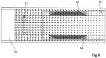
- Figure 8 schematically illustrates the field lines in the arrangement of Figure 6 and 7 .
- the field lines propagate parallelly to the longitudinal axis of the electronic cigarette between the two coils 62 and 64 and axially within the respective coils. Therefore, the intensity of the field captured by the antenna 6 can be considered as doubled with respect to a single coil.
- the proposed arrangement increases the inductance of the tag that is usually difficult to achieve in this technology, especially with the proximity of the metallic housing.
- antenna 6 can be made of aluminum and in standard pitch and low side. Indeed, in the RFID tag manufacturing, the cost is generally lower when the dimension of the tag is around 30x15mm and then increases when the size is lower (for example 10x10 mm) or higher (for example, 50x30 mm). In the first case, this is due to the usage of more expensive technology to reach small pitch (for example replacement of aluminum by copper or using aluminum edge technology with smaller pitch and double side antenna).
- Another advantage is that the described embodiments take advantage of the shape and geometric properties of the product. Indeed, the small size accessories or consumables which are inducing the constraint of a small tag have the advantage to allow the bending of the antenna around the product.
- Another advantage is that the operation of the antenna is not impacted by the position (axial rotation of 180°) of the cartridge. This provides comfort to the user who is free to choose the orientation of the cartridge.
- the practical implementation of the embodiments and variants described herein is within the capabilities of those skilled in the art based on the functional description provided hereinabove.
- the sizing of the antennas and their shape depend of the application and of the shape of the devices to which they are associated.
Landscapes
- Engineering & Computer Science (AREA)
- Computer Networks & Wireless Communication (AREA)
- Signal Processing (AREA)
- Computer Hardware Design (AREA)
- Microelectronics & Electronic Packaging (AREA)
- Physics & Mathematics (AREA)
- General Physics & Mathematics (AREA)
- Theoretical Computer Science (AREA)
- Near-Field Transmission Systems (AREA)
Description
- The present disclosure relates generally to electronic circuits and more particularly to a wireless communication system using RFID (Radio Frequency Identification) technology, Near Field Communication (NFC) technology or the like. The present disclosure more particularly applies to communications between two mechanically associated devices, and more particularly to an electronic cigarette device.
- Communication systems with electromagnetic transponders are more and more frequent, particularly since the development of proximity or near field radiofrequency communication based on RFID or NFC technologies. Standards ISO-15693 and ISO-14443 disclose such kind of radiofrequency communications.
- Such systems use the power generated by a radio frequency field of a terminal to communicate with, and most often to power, an electromagnetic transponder.
- NFC devices and NFC communications are used for exchanging information between two devices, generally named reader and tag. The reader generates, via an antenna, an electromagnetic field. The tag also comprises an antenna, which is excited when in close coupling with the antenna of the reader.
- In some cases, the communication between a reader and a tag is polluted or perturbated by the environment of the antenna and more particularly by the mechanical surrounding of the antennas of the reader and of the tag.
-
US2005/0242959 discloses an IC-TAG provided with three-dimensional antenna. -
EP1031940 discloses a circuit of multiple coplanar antennas. -
WO 2012009776 discloses a magnetic coupling antenna and system for exchanging data comprising the same. -
US 2018/0179887 discloses an antenna for downhole communication. -
US 2014/0184462 discloses an antenna module radio communication device. -
US2015/0097741 discloses an antenna with multifrequency capability for miniaturized applications. -
WO 2006/053692 discloses an improved radio-frequency identifying device. - There is a need for improving the antennas for RF communications.
- One embodiment addresses all or some of the drawbacks of known NFC systems.
- The invention is defined by the appended claims.
- The foregoing features and advantages, as well as others, will be described in detail in the following description of specific embodiments given by way of illustration and not limitation with reference to the accompanying drawings, in which:
-
Figure 1 is a simplified view, in the form of blocks, of an example of a contactless near field communication system (NFC); -
Figure 2 is a block diagram partially illustrating an embodiment of circuits of a near field communication device; -
Figure 3 represents schematic views (a) and (b) of an electronic cigarette; -
Figure 4 illustrates an embodiment of an antenna before its mounting in a device; -
Figure 5 illustrates the antenna ofFigure 4 mounted in a device; -
Figure 6 is a perspective, partial and schematic view of a wireless communication system for an electronic cigarette; -
Figure 7 is a longitudinal section of the system ofFigure 6 ; and -
Figure 8 illustrates the field lines of an embodiment of a wireless communication system. - Like features have been designated by like references in the various figures. In particular, the structural and/or functional features that are common among the various embodiments may have the same references and may dispose identical structural, dimensional and material properties.
- For the sake of clarity, only the operations and elements that are useful for an understanding of the embodiments described herein have been illustrated and described in detail. In particular, the communication protocols between a reader and a tag are not described in detail, the described embodiments being compliant with usual NFC communication protocols. Furthermore, the constitution details and operation of an electronic cigarette are not described in detail, the described embodiments being compliant with usual electronic cigarettes.
-
Figure 1 is a simplified view, in the form of blocks, of an example of a contactless near field communication system to which apply the disclosed embodiments. The system can be any RF communication system like those of standards ISO-155693, ISO-14443, NFC Forum, RFIC and like. - A terminal or reader 1 (READER) comprises various electronic circuits for generating a radio frequency signal transmitted by means of an
antenna 12. The radio frequency field generated by terminal or reader 1 is detected by one or a plurality of electromagnetic transponders, for example, an electronic tag 2 (TAG) located in the range.Tag 2 itself comprises anantenna 6 and electronic circuits.Tag 2 generally extracts the power necessary to the operation of the circuits that it comprises from the radio frequency field generated by terminal 1. Therespective antennas tag 2 are part of oscillating circuits also comprising capacitances. The oscillating circuits of the terminal 1 and of thetag 2 are preferably tuned at least approximately at the same frequency, preferably at the same frequency, for example 13,56 MHz. - When the reader 1 emits an electromagnetic field to initiate a communication with the
tag 2, the field is captured bytag 2 as soon as it is within its range. The coupling between the two oscillating circuits (that of theantenna 6 and that of the antenna 12) results in a variation of the load formed by the circuits oftag 2 on the field generation oscillating circuit of reader 1. In practice, the corresponding phase or amplitude variation of the emitted field is detected by reader 1, which for example then starts a protocol of NFC communication withtag 2. - For a communication in the direction from terminal 1 to
tag 2, terminal 1 modulates, for example in amplitude, the remote supply carrier (typically at 13.56 MHz). In the direction fromtag 2 to terminal 1, the communication is performed by modification of the load (retromodulation) formed by the tag on the oscillating circuit of the terminal, for example, in amplitude modulation or in phase modulation. -
Figure 2 is a block diagram partially illustrating an embodiment of circuits of a near field communication device, like thetag 2 ofFigure 1 . - In a simplified manner,
tag 2 comprises at least one series or parallelresonant circuit 24. In the case of a parallel resonant circuit as represented, thecircuit 24 comprises an inductorL forming antenna 6 in parallel with a capacitive element C. Theresonant circuit 24 senses the radio frequency field of a terminal (1,Figure 1 ).Resonant circuit 24 is coupled to anintegrated circuit 4 comprising various electronic circuits among which, generally, a unit 42 (PU) for processing the signals received from the terminal and for generating the retromodulation signal.Integrated circuit 4 also generally comprises various circuits (impedance matching, switching, coupling and other such circuits) not represented betweenresonant circuit 24 andprocessing unit 42. Capacitor C is, in this example, integrated incircuit 4. - In the represented embodiment,
tag 2 draws its power from the electromagnetic field that it picks up. In this case, the tag furthermore includes abridge rectifier 44, the input terminals of which are connected to the terminals of the resonant circuit, i.e. the terminals of the parallel association of inductor L and capacitor C, and the output terminals of which are coupled (possibly via a voltage regulator, not shown) tocircuit 42. Generally, in this case, adirect link 46 is also provided betweenresonant circuit 24 andprocessing unit 42 and, more particularly, its radiofrequency reception chain, to provide a RF signal unfiltered by the rectifier. - In the applications to which more particularly apply the embodiments which are described, the reader and the tag are associated to two different physical devices, which need to communicate together.
- The need for a wireless communication between these two devices may generate constraints on the antennas due to the shape and or to the size of each device.
- The embodiments are described in relation with an example of application to an electronic cigarette and more particularly to a system for authenticating a cartridge of an electronic cigarette.
-
Figure 3 represents, very schematically, an embodiment of anelectronic cigarette 5. -
Figure 3(a) represent the electronic cigarette, mounted, i.e. ready for use.Figure 3(b) illustrate the two parts of the electronic cigarette aimed to be respectively associated with a reader and with a tag of a RF communication system. - An
electronic cigarette 5, or e-cigarette, mainly comprises at least amouthpiece 52, a cartridge ortank 54 containing a liquid solution, and abody 56.Mouthpiece 52 andtank 54 can be a single piece element.Body 56 comprises amongst others abattery 562 and anelectronic circuit 564 including a microprocessor and an NFC reader. An atomizer not shown is included in thebody 56 or in thecartridge 54. The atomizer comprises a heating element that vaporizes the liquid and wicking material that draws liquid onto the heating element. The atomizer creates an aerosolized vapor, which a user inhales and that provides a flavor and feel like a cigarette. If the atomizer is included in the cartridge,cartridge 54 andbody 56 comprise face to faceelectrical terminals 545 and 565 (Figure 3(b) ) to power the atomizer. - As shown in
Figure 3(b) , thebody 56 comprises ahousing 568 which defines a space for receiving thecartridge 54. Thehousing 568 is, for example, metallic and the walls of the cartridge are generally made of plastic. - The cartridge or
tank 54 is changeable and can be considered as an accessory or a consumable of theelectronic cigarette 5. It may be desirable to check the authenticity of the tank, i.e. that the tank has been produced by an authorized manufacturer. - More generally, the embodiments apply to the verification of the authenticity of a product (the cartridge) associated with an apparatus (the body of the electronic cigarette) by circuits respectively contained in the product and in the apparatus, using proximity radiofrequency communications (RFID, NFC, 15693, 14443, etc.) between the apparatus and the product.
- The presence of products, consumables or accessories, not genuine of an apparatus constitutes a problem for the manufacturer of the apparatus and for the authorized suppliers of the authentic products (consumables or accessories). especially, in situation where a customer returns the product to the manufacturer for functional problems, it is important to be able to distinguish authentic products from non-genuine products. For this, the associated apparatus and products are equipped with electronic circuits running authenticity verification protocols when setting up a new product, when the apparatus is switched on, periodically, during a need for replacement of the product, etc.
- According to these embodiments, the authentication uses RF communication, for example, a Radio Frequency Identification (RFID). A reader (1,
figure 1 ) is included or attached to the apparatus and atag 2 is included or attached to the product.Tag 2 contains a unique identifier (ID) and one aim of the communication is to check this identifier, by the terminal, to authenticate the tag. The tag is preferably powered by extracting energy from the field generated by the terminal 1. - According to the embodiment to an
electronic cigarette 5, thetag 2 is carried by (attached or integrated to) thecartridge 54 and the reader is carried by (attached or integrated to) thebody 56. - Various constraints are due to the size and shape of the electronic cigarette, and more generally of products and apparatus carrying a tag or a reader and their antennas.
- First, the space in the cartridge and in the cigarette is limited, which conditions the size of the antenna. In particular, the reduced size of the cartridge does not allow to provide a large antenna.
- In some cases, like in the electronic cigarette taken as example, the metallic parts create shielding for the radiofrequency communication. Indeed, electromagnetic field used for RF communications is influenced by any object whose electrical parameters differ from the electrical parameters of the media in which the field is propagating. For near field communications at high frequencies (typically from 3 MHz to 30 MHz), the electromagnetic field is usually mostly composed of magnetic field, whose parameters are sensitive to the conductivity and permeability of the influencing bodies. Highly conducting bodies (composed e.g. from copper or aluminum) are acting as a shield for the field and therefore limit the communication. In the example of the
electronic cigarette 5, thehousing 568 is metallic and defines a cavity where thecartridge 54 is placed. Even though there is usually no conducting body in the direct path between the reader and the tag, the proximity of the metal of the housing is influencing (attenuating) the communication. - More generally, even if the constraint due to the metallic parts is lower, the space available for the antenna is directed by the product and is usually reduced with respect to the space ideally needed for an optimal communication.
- Another difficulty is that the shape and dimensions of the electronic cigarette do not allow to place the reader antenna and the tag antenna side by side.
-
Figure 4 illustrates an embodiment of an antenna before its mounting in a device like thecartridge 54 ofelectronic cigarette 5 ofFigure 3 . -
Figure 5 illustrates the antenna ofFigure 4 mounted in a device like thecartridge 54 electronic cigarette ofFigure 2 . - An
antenna 6 according to the embodiments, which are described, comprises twoplanar coils - Each
coil windings - The number of turns depend on the inductance, which is desired for the antenna and on the available space.
-
Coils 62 et 64 are electrically connected in series via twoconductive tracks internal ends external ends terminals antenna 6, to be connected to capacitor C (Figure 2 ) andintegrated circuit 4 are defined by an interruption of the continuity of the electrical circuit forming theantenna 6. In the example illustrated inFigure 4 , theterminals coils 64. However, theterminals integrated circuit 4 in the cartridge. - As it can be seen in
Figures 4 and 5 , the electrical connection of thecoils - Capacitor C can be a specific component or be formed by the parasitic or intrinsic capacitance of the antenna. According to a preferred embodiment represented in
Figure 2 , capacitor C is provided by thechip 4 itself. - The shape of the windings of
coils antenna 6 is associated. - The mounting of an
antenna 6 of the type illustrated byFigures 4 and 5 comprises the step of bending the antenna to bring thecoils tracks antenna 6 is composed of twoinductors - In the example of
Figure 5 , thecoils cartridge 54, which has an ovoid section.Coils - More generally and this will be better understood in relation with
Figure 8 , the distance separating the coils is preferably chosen to allow field lines to be propagated, between the twocoils -
Antenna 6 is preferably flexible to allow it to fit with the device to which it is associated. -
Figure 6 is a perspective, partial and schematic view of the locations ofantennas -
Figure 7 is a longitudinal section of the system ofFigure 5 . - In the embodiment which is represented, the
antenna 12 of the reader is carried by thebody 56 of the electronic cigarette. More particularly,antenna 12 has the form of a planar coil placed at the top of body 56 (above the battery 562), perpendicularly to the longitudinal axis (v). - Thanks to the fact that the mechanical relation between the
body 56 and thecartridge 54 is fixed (the cartridge is removable from thebody 56 but has always the same position with respect to thebody 56, when mounted on it), the coupling distance betweenantennas - In the preferred embodiment represented,
antenna 12 has its central axis perpendicular to the central axis of the coils ofantenna 6. In other words,antenna 12 is coaxial with the body 56 (axis v) and the axis of antenna 6 (common axis ofcoils 62 and 66) if perpendicular to the longitudinal axis v of theelectronic cigarette 5. - As alternative embodiments, the
antenna 12 of thebody 56 can have a different shape than represented. For example,antenna 12, can be non-planar, can be made of windings having a central axis parallel, but not coaxial to the central axis of thecoils antenna 6, can be formed of planar flexible antenna to be parallel to the housing of thebody 56, etc. - To improve the coupling between
antenna ferrite sheets 7 can be associated to thecoils Ferrite sheets 7 on the inner walls of thehousing 568 provide shielding effect of the metallic walls. Each ferrite sheets have high permeability and guide the field lines.Ferrite sheets 7 can be made of a sticker on which is deposited as layer of ferrite material with high permeability. - In the embodiment where the
cartridge 54 is introduced in thehousing 568 of thebody 56 of the electronic cigarette,ferrite sheets 7 are preferably provided in the housing, which means associated to the apparatus and not to the consumables, and therefore the cost impact on the system is reduced. As an alternative, the ferrite sheets can however be carried by the cartridge. - In the embodiment shown in
Figure 7 ,sheets 7 of ferrite are interposed between the housing around the cartridge 542 and thecoils Coils antenna 6 are then, in operation, coplanar to one or several sheets of ferrite. - The ferrite sheet (s) can line the totality of the internal side of the
housing 568 around cartridge 542, but for cost saving, are preferably only provided to screencoils antenna 12 - The shape of the
antenna 6 increases the inductance of bothantenna 6 and mutual inductance betweenantenna -
Figure 8 schematically illustrates the field lines in the arrangement ofFigure 6 and 7 . - As it can be seen, thanks to the space between
coils coils 12, the field lines propagate parallelly to the longitudinal axis of the electronic cigarette between the twocoils antenna 6 can be considered as doubled with respect to a single coil. - The proposed arrangement increases the inductance of the tag that is usually difficult to achieve in this technology, especially with the proximity of the metallic housing.
- An advantage of the embodiments, which have been described is that they are compatible with cost constraints, particularly present for disposables like cartridges for electronic cigarettes, keeping the cost at an acceptable level for an industrialization compatible with the market. For example,
antenna 6 can be made of aluminum and in standard pitch and low side. Indeed, in the RFID tag manufacturing, the cost is generally lower when the dimension of the tag is around 30x15mm and then increases when the size is lower (for example 10x10 mm) or higher (for example, 50x30 mm). In the first case, this is due to the usage of more expensive technology to reach small pitch (for example replacement of aluminum by copper or using aluminum edge technology with smaller pitch and double side antenna). - Another advantage is that the described embodiments take advantage of the shape and geometric properties of the product. Indeed, the small size accessories or consumables which are inducing the constraint of a small tag have the advantage to allow the bending of the antenna around the product.
- Another advantage is that the operation of the antenna is not impacted by the position (axial rotation of 180°) of the cartridge. This provides comfort to the user who is free to choose the orientation of the cartridge.
- Various embodiments and variants have been described. Those skilled in the art will understand that certain features of these embodiments can be combined, and other variants will readily occur to those skilled in the art. In particular, the system which has been described can be applied to other associations apparatus-product than an electronic cigarette in which similar problem are present, for example a printer and its cartridges. Furthermore, the specific design of the antenna with two coils face to face and electrically in series can more generally be used in any proximity radiofrequency communication system based on standards ISO-15693 and ISO-14443 or on RFID technology or NFC Forum.
- Finally, the practical implementation of the embodiments and variants described herein is within the capabilities of those skilled in the art based on the functional description provided hereinabove. In particular, the sizing of the antennas and their shape depend of the application and of the shape of the devices to which they are associated.
Claims (8)
- An electronic cigarette (5) comprising :a cartridge (54) ;a body (56) ;characterized in thatthe electronic cigarette further comprises a system for wireless communication comprising :a tag (2) having a first antenna (6), said tag being carried by the cartridge;a reader (1) included in said system for wireless communication and having a second antenna (12) made of a planar coil and carried by said body,wherein the first antenna comprises :a first planar coil (62) ; anda second planar coil (64) ;the first and second planar coils of said first antenna being electrically connected in series, placed on two opposite sides of the cartridge, said coils being mechanically face to face ; andthe cartridge (54) being removable from the body but having always the same position with respect to the body, when mounted on it, such that the distance between the first antenna and the second antenna is then constant, the second antenna (12) having a central axis perpendicular to the central axis of the coils (62, 64) of the first antenna (6).
- The electronic cigarette of claim 1, in which the coils are coaxial.
- The electronic cigarette of claim 1 or 2, in which the distance separating the coils (62, 64) of the first antenna is chosen to allow field lines to be propagated, between the two coils, in a direction parallel to the surface of the coils.
- The electronic cigarette of any of claims 1 to 3, wherein the coils (62, 64) of the first antenna are made of windings (622, 642) of conductive tracks.
- The electronic cigarette of any of claims 1 to 4, wherein the internal ends (624, 644) of the coils (62, 64) of the first antenna are electrically coupled to each other, and wherein the external ends (642, 644) of the coils are electrically coupled to each other.
- The electronic cigarette of claim 5, wherein the internal ends (624, 644) of the coils (62, 64) of the first antenna are electrically connected to each other, and wherein the external ends (642, 644) of the coils are electrically connected to each other.
- The electronic cigarette of any of claims 1 to 6, wherein one (64) of the coils (62, 64) of the first antenna is interrupted in its innermost winding to define two terminals (61, 63) of the antenna (6).
- The electronic cigarette according to any of claims 1 to 7, further comprising one or several sheets (7) of ferrite, each coil (62, 64) of the first antenna (6) being coplanar to this or these sheets (7) of ferrite.
Priority Applications (2)
| Application Number | Priority Date | Filing Date | Title |
|---|---|---|---|
| EP18186154.3A EP3599574B1 (en) | 2018-07-27 | 2018-07-27 | Antenna and system for rf communications |
| US16/521,757 US11031672B2 (en) | 2018-07-27 | 2019-07-25 | Antenna and system for RF communications |
Applications Claiming Priority (1)
| Application Number | Priority Date | Filing Date | Title |
|---|---|---|---|
| EP18186154.3A EP3599574B1 (en) | 2018-07-27 | 2018-07-27 | Antenna and system for rf communications |
Publications (2)
| Publication Number | Publication Date |
|---|---|
| EP3599574A1 EP3599574A1 (en) | 2020-01-29 |
| EP3599574B1 true EP3599574B1 (en) | 2023-05-31 |
Family
ID=63103767
Family Applications (1)
| Application Number | Title | Priority Date | Filing Date |
|---|---|---|---|
| EP18186154.3A Active EP3599574B1 (en) | 2018-07-27 | 2018-07-27 | Antenna and system for rf communications |
Country Status (2)
| Country | Link |
|---|---|
| US (1) | US11031672B2 (en) |
| EP (1) | EP3599574B1 (en) |
Families Citing this family (8)
| Publication number | Priority date | Publication date | Assignee | Title |
|---|---|---|---|---|
| US10959459B2 (en) * | 2018-05-16 | 2021-03-30 | Rai Strategic Holdings, Inc. | Voltage regulator for an aerosol delivery device |
| KR20220156879A (en) * | 2020-03-23 | 2022-11-28 | 필립모리스 프로덕츠 에스.에이. | Aerosol Generating System with Resonant Circuit for Cartridge Recognition |
| KR102534235B1 (en) * | 2020-07-07 | 2023-05-18 | 주식회사 케이티앤지 | Aerosol generating apparatus |
| GB202010923D0 (en) * | 2020-07-15 | 2020-08-26 | Frisense Ltd | Electronic tag |
| US20230284691A1 (en) * | 2020-08-10 | 2023-09-14 | Jt International Sa | Aerosol Generation Assembly Comprising an Aerosol Generation Device and a Cartridge with NFC |
| US20220111160A1 (en) * | 2020-10-12 | 2022-04-14 | Sapa Investment Group Inc. | Vaporization Apparatus and Authorization System |
| DE102021102609A1 (en) | 2021-02-04 | 2022-08-04 | Infineon Technologies Ag | Electronic cigarette device, electronic cigarette, method of forming an electronic cigarette device and method of forming an electronic cigarette |
| WO2022233827A1 (en) * | 2021-05-05 | 2022-11-10 | Jt International Sa | Aerosol-generating article with a capacitively coupled rfid tag |
Citations (4)
| Publication number | Priority date | Publication date | Assignee | Title |
|---|---|---|---|---|
| WO2006053692A1 (en) * | 2004-11-19 | 2006-05-26 | Smart Res S.R.L. | Improved radio-frequency identifying device |
| US20140184462A1 (en) * | 2012-06-04 | 2014-07-03 | Murata Manufacturing Co., Ltd. | Antenna module and radio communication device |
| US20150097741A1 (en) * | 2013-10-04 | 2015-04-09 | Infineon Technologies Ag | Antenna with Multifrequency Capability for Miniaturized Applications |
| US20180179887A1 (en) * | 2016-12-23 | 2018-06-28 | Weatherford U.K. Limited | Antenna for downhole communication |
Family Cites Families (7)
| Publication number | Priority date | Publication date | Assignee | Title |
|---|---|---|---|---|
| US6069564A (en) * | 1998-09-08 | 2000-05-30 | Hatano; Richard | Multi-directional RFID antenna |
| EP1031940A1 (en) * | 1999-02-24 | 2000-08-30 | Sihl GmbH | Device comprising a plurality of electronic circuits |
| JP4205823B2 (en) * | 1999-10-04 | 2009-01-07 | 大日本印刷株式会社 | IC card |
| JP2005316742A (en) * | 2004-04-28 | 2005-11-10 | Fuji Xerox Co Ltd | Ic tag |
| BRPI1002245A2 (en) * | 2010-07-23 | 2012-06-05 | Albuquerque Lambert Jorge De | self-protected antenna with application to (but not limited to) RFID electronic documents intrinsically protected against clandestine activation |
| US20150188227A1 (en) * | 2013-12-31 | 2015-07-02 | Identive Group, Inc. | Antenna for near field communication, antenna arrangement, transponder with antenna, flat panel and methods of manufacturing |
| WO2015106390A1 (en) * | 2014-01-14 | 2015-07-23 | 吉瑞高新科技股份有限公司 | Electronic cigarette identification device, electronic cigarette case, and method for identifying electronic cigarette |
-
2018
- 2018-07-27 EP EP18186154.3A patent/EP3599574B1/en active Active
-
2019
- 2019-07-25 US US16/521,757 patent/US11031672B2/en active Active
Patent Citations (4)
| Publication number | Priority date | Publication date | Assignee | Title |
|---|---|---|---|---|
| WO2006053692A1 (en) * | 2004-11-19 | 2006-05-26 | Smart Res S.R.L. | Improved radio-frequency identifying device |
| US20140184462A1 (en) * | 2012-06-04 | 2014-07-03 | Murata Manufacturing Co., Ltd. | Antenna module and radio communication device |
| US20150097741A1 (en) * | 2013-10-04 | 2015-04-09 | Infineon Technologies Ag | Antenna with Multifrequency Capability for Miniaturized Applications |
| US20180179887A1 (en) * | 2016-12-23 | 2018-06-28 | Weatherford U.K. Limited | Antenna for downhole communication |
Also Published As
| Publication number | Publication date |
|---|---|
| EP3599574A1 (en) | 2020-01-29 |
| US11031672B2 (en) | 2021-06-08 |
| US20200036080A1 (en) | 2020-01-30 |
Similar Documents
| Publication | Publication Date | Title |
|---|---|---|
| US11031672B2 (en) | Antenna and system for RF communications | |
| US8704716B2 (en) | Antenna device and mobile communication terminal | |
| US9805861B2 (en) | Communication terminal including close-proximity communication coil, power transmission coil, and metal plate | |
| US9016592B2 (en) | Antenna device and communication terminal apparatus | |
| EP2669995B1 (en) | Active load modulation antenna | |
| US9231305B2 (en) | Wireless IC device | |
| JP5610098B2 (en) | Communication terminal device | |
| CN103620868B (en) | Antenna device and communication terminal device | |
| EP3115937B1 (en) | Multiple frequency transponder | |
| US9024725B2 (en) | Communication terminal and information processing system | |
| JP5026522B2 (en) | Optimized reading method and system for transponders for high frequency communications using passive resonant circuits | |
| US20120223149A1 (en) | Antenna and rfid device | |
| KR20120103501A (en) | Power-receiving device, wireless power-feeding system including power-receiving device, and wireless communication system including power-receiving device | |
| EP2453523B1 (en) | Transmission / reception antenna and transmission / reception device using same | |
| JP5975211B2 (en) | Communication terminal | |
| US20130050035A1 (en) | Communication terminal and card antenna module | |
| US11043751B2 (en) | NFC antenna device in a metallic environment | |
| US20120182128A1 (en) | Communication terminal and information processing system | |
| JP2011193245A (en) | Antenna device, radio communication device and radio communication terminal | |
| US20170207544A1 (en) | Slot antenna structure for electronic tag | |
| EP4430516A1 (en) | A radio frequency identification reader | |
| JPWO2020026482A1 (en) | RFID system |
Legal Events
| Date | Code | Title | Description |
|---|---|---|---|
| PUAI | Public reference made under article 153(3) epc to a published international application that has entered the european phase |
Free format text: ORIGINAL CODE: 0009012 |
|
| STAA | Information on the status of an ep patent application or granted ep patent |
Free format text: STATUS: THE APPLICATION HAS BEEN PUBLISHED |
|
| AK | Designated contracting states |
Kind code of ref document: A1 Designated state(s): AL AT BE BG CH CY CZ DE DK EE ES FI FR GB GR HR HU IE IS IT LI LT LU LV MC MK MT NL NO PL PT RO RS SE SI SK SM TR |
|
| AX | Request for extension of the european patent |
Extension state: BA ME |
|
| STAA | Information on the status of an ep patent application or granted ep patent |
Free format text: STATUS: REQUEST FOR EXAMINATION WAS MADE |
|
| 17P | Request for examination filed |
Effective date: 20200219 |
|
| RBV | Designated contracting states (corrected) |
Designated state(s): AL AT BE BG CH CY CZ DE DK EE ES FI FR GB GR HR HU IE IS IT LI LT LU LV MC MK MT NL NO PL PT RO RS SE SI SK SM TR |
|
| STAA | Information on the status of an ep patent application or granted ep patent |
Free format text: STATUS: EXAMINATION IS IN PROGRESS |
|
| 17Q | First examination report despatched |
Effective date: 20200526 |
|
| GRAP | Despatch of communication of intention to grant a patent |
Free format text: ORIGINAL CODE: EPIDOSNIGR1 |
|
| STAA | Information on the status of an ep patent application or granted ep patent |
Free format text: STATUS: GRANT OF PATENT IS INTENDED |
|
| INTG | Intention to grant announced |
Effective date: 20230112 |
|
| GRAS | Grant fee paid |
Free format text: ORIGINAL CODE: EPIDOSNIGR3 |
|
| GRAA | (expected) grant |
Free format text: ORIGINAL CODE: 0009210 |
|
| STAA | Information on the status of an ep patent application or granted ep patent |
Free format text: STATUS: THE PATENT HAS BEEN GRANTED |
|
| AK | Designated contracting states |
Kind code of ref document: B1 Designated state(s): AL AT BE BG CH CY CZ DE DK EE ES FI FR GB GR HR HU IE IS IT LI LT LU LV MC MK MT NL NO PL PT RO RS SE SI SK SM TR |
|
| REG | Reference to a national code |
Ref country code: GB Ref legal event code: FG4D Ref country code: CH Ref legal event code: EP |
|
| REG | Reference to a national code |
Ref country code: DE Ref legal event code: R096 Ref document number: 602018050388 Country of ref document: DE |
|
| REG | Reference to a national code |
Ref country code: AT Ref legal event code: REF Ref document number: 1571380 Country of ref document: AT Kind code of ref document: T Effective date: 20230615 |
|
| REG | Reference to a national code |
Ref country code: IE Ref legal event code: FG4D |
|
| REG | Reference to a national code |
Ref country code: LT Ref legal event code: MG9D |
|
| REG | Reference to a national code |
Ref country code: NL Ref legal event code: MP Effective date: 20230531 |
|
| REG | Reference to a national code |
Ref country code: AT Ref legal event code: MK05 Ref document number: 1571380 Country of ref document: AT Kind code of ref document: T Effective date: 20230531 |
|
| PG25 | Lapsed in a contracting state [announced via postgrant information from national office to epo] |
Ref country code: SE Free format text: LAPSE BECAUSE OF FAILURE TO SUBMIT A TRANSLATION OF THE DESCRIPTION OR TO PAY THE FEE WITHIN THE PRESCRIBED TIME-LIMIT Effective date: 20230531 Ref country code: NO Free format text: LAPSE BECAUSE OF FAILURE TO SUBMIT A TRANSLATION OF THE DESCRIPTION OR TO PAY THE FEE WITHIN THE PRESCRIBED TIME-LIMIT Effective date: 20230831 Ref country code: ES Free format text: LAPSE BECAUSE OF FAILURE TO SUBMIT A TRANSLATION OF THE DESCRIPTION OR TO PAY THE FEE WITHIN THE PRESCRIBED TIME-LIMIT Effective date: 20230531 Ref country code: AT Free format text: LAPSE BECAUSE OF FAILURE TO SUBMIT A TRANSLATION OF THE DESCRIPTION OR TO PAY THE FEE WITHIN THE PRESCRIBED TIME-LIMIT Effective date: 20230531 |
|
| PG25 | Lapsed in a contracting state [announced via postgrant information from national office to epo] |
Ref country code: RS Free format text: LAPSE BECAUSE OF FAILURE TO SUBMIT A TRANSLATION OF THE DESCRIPTION OR TO PAY THE FEE WITHIN THE PRESCRIBED TIME-LIMIT Effective date: 20230531 Ref country code: PL Free format text: LAPSE BECAUSE OF FAILURE TO SUBMIT A TRANSLATION OF THE DESCRIPTION OR TO PAY THE FEE WITHIN THE PRESCRIBED TIME-LIMIT Effective date: 20230531 Ref country code: NL Free format text: LAPSE BECAUSE OF FAILURE TO SUBMIT A TRANSLATION OF THE DESCRIPTION OR TO PAY THE FEE WITHIN THE PRESCRIBED TIME-LIMIT Effective date: 20230531 Ref country code: LV Free format text: LAPSE BECAUSE OF FAILURE TO SUBMIT A TRANSLATION OF THE DESCRIPTION OR TO PAY THE FEE WITHIN THE PRESCRIBED TIME-LIMIT Effective date: 20230531 Ref country code: LT Free format text: LAPSE BECAUSE OF FAILURE TO SUBMIT A TRANSLATION OF THE DESCRIPTION OR TO PAY THE FEE WITHIN THE PRESCRIBED TIME-LIMIT Effective date: 20230531 Ref country code: IS Free format text: LAPSE BECAUSE OF FAILURE TO SUBMIT A TRANSLATION OF THE DESCRIPTION OR TO PAY THE FEE WITHIN THE PRESCRIBED TIME-LIMIT Effective date: 20230930 Ref country code: HR Free format text: LAPSE BECAUSE OF FAILURE TO SUBMIT A TRANSLATION OF THE DESCRIPTION OR TO PAY THE FEE WITHIN THE PRESCRIBED TIME-LIMIT Effective date: 20230531 Ref country code: GR Free format text: LAPSE BECAUSE OF FAILURE TO SUBMIT A TRANSLATION OF THE DESCRIPTION OR TO PAY THE FEE WITHIN THE PRESCRIBED TIME-LIMIT Effective date: 20230901 |
|
| PG25 | Lapsed in a contracting state [announced via postgrant information from national office to epo] |
Ref country code: FI Free format text: LAPSE BECAUSE OF FAILURE TO SUBMIT A TRANSLATION OF THE DESCRIPTION OR TO PAY THE FEE WITHIN THE PRESCRIBED TIME-LIMIT Effective date: 20230531 |
|
| PG25 | Lapsed in a contracting state [announced via postgrant information from national office to epo] |
Ref country code: SK Free format text: LAPSE BECAUSE OF FAILURE TO SUBMIT A TRANSLATION OF THE DESCRIPTION OR TO PAY THE FEE WITHIN THE PRESCRIBED TIME-LIMIT Effective date: 20230531 |
|
| PG25 | Lapsed in a contracting state [announced via postgrant information from national office to epo] |
Ref country code: SM Free format text: LAPSE BECAUSE OF FAILURE TO SUBMIT A TRANSLATION OF THE DESCRIPTION OR TO PAY THE FEE WITHIN THE PRESCRIBED TIME-LIMIT Effective date: 20230531 Ref country code: SK Free format text: LAPSE BECAUSE OF FAILURE TO SUBMIT A TRANSLATION OF THE DESCRIPTION OR TO PAY THE FEE WITHIN THE PRESCRIBED TIME-LIMIT Effective date: 20230531 Ref country code: RO Free format text: LAPSE BECAUSE OF FAILURE TO SUBMIT A TRANSLATION OF THE DESCRIPTION OR TO PAY THE FEE WITHIN THE PRESCRIBED TIME-LIMIT Effective date: 20230531 Ref country code: PT Free format text: LAPSE BECAUSE OF FAILURE TO SUBMIT A TRANSLATION OF THE DESCRIPTION OR TO PAY THE FEE WITHIN THE PRESCRIBED TIME-LIMIT Effective date: 20231002 Ref country code: EE Free format text: LAPSE BECAUSE OF FAILURE TO SUBMIT A TRANSLATION OF THE DESCRIPTION OR TO PAY THE FEE WITHIN THE PRESCRIBED TIME-LIMIT Effective date: 20230531 Ref country code: DK Free format text: LAPSE BECAUSE OF FAILURE TO SUBMIT A TRANSLATION OF THE DESCRIPTION OR TO PAY THE FEE WITHIN THE PRESCRIBED TIME-LIMIT Effective date: 20230531 Ref country code: CZ Free format text: LAPSE BECAUSE OF FAILURE TO SUBMIT A TRANSLATION OF THE DESCRIPTION OR TO PAY THE FEE WITHIN THE PRESCRIBED TIME-LIMIT Effective date: 20230531 |
|
| PG25 | Lapsed in a contracting state [announced via postgrant information from national office to epo] |
Ref country code: MC Free format text: LAPSE BECAUSE OF FAILURE TO SUBMIT A TRANSLATION OF THE DESCRIPTION OR TO PAY THE FEE WITHIN THE PRESCRIBED TIME-LIMIT Effective date: 20230531 |
|
| PG25 | Lapsed in a contracting state [announced via postgrant information from national office to epo] |
Ref country code: MC Free format text: LAPSE BECAUSE OF FAILURE TO SUBMIT A TRANSLATION OF THE DESCRIPTION OR TO PAY THE FEE WITHIN THE PRESCRIBED TIME-LIMIT Effective date: 20230531 |
|
| REG | Reference to a national code |
Ref country code: CH Ref legal event code: PL |
|
| REG | Reference to a national code |
Ref country code: DE Ref legal event code: R097 Ref document number: 602018050388 Country of ref document: DE |
|
| REG | Reference to a national code |
Ref country code: BE Ref legal event code: MM Effective date: 20230731 |
|
| PG25 | Lapsed in a contracting state [announced via postgrant information from national office to epo] |
Ref country code: LU Free format text: LAPSE BECAUSE OF NON-PAYMENT OF DUE FEES Effective date: 20230727 |
|
| PG25 | Lapsed in a contracting state [announced via postgrant information from national office to epo] |
Ref country code: LU Free format text: LAPSE BECAUSE OF NON-PAYMENT OF DUE FEES Effective date: 20230727 |
|
| PLBE | No opposition filed within time limit |
Free format text: ORIGINAL CODE: 0009261 |
|
| STAA | Information on the status of an ep patent application or granted ep patent |
Free format text: STATUS: NO OPPOSITION FILED WITHIN TIME LIMIT |
|
| GBPC | Gb: european patent ceased through non-payment of renewal fee |
Effective date: 20230831 |
|
| REG | Reference to a national code |
Ref country code: IE Ref legal event code: MM4A |
|
| PG25 | Lapsed in a contracting state [announced via postgrant information from national office to epo] |
Ref country code: CH Free format text: LAPSE BECAUSE OF NON-PAYMENT OF DUE FEES Effective date: 20230731 |
|
| PG25 | Lapsed in a contracting state [announced via postgrant information from national office to epo] |
Ref country code: SI Free format text: LAPSE BECAUSE OF FAILURE TO SUBMIT A TRANSLATION OF THE DESCRIPTION OR TO PAY THE FEE WITHIN THE PRESCRIBED TIME-LIMIT Effective date: 20230531 |
|
| 26N | No opposition filed |
Effective date: 20240301 |
|
| PG25 | Lapsed in a contracting state [announced via postgrant information from national office to epo] |
Ref country code: SI Free format text: LAPSE BECAUSE OF FAILURE TO SUBMIT A TRANSLATION OF THE DESCRIPTION OR TO PAY THE FEE WITHIN THE PRESCRIBED TIME-LIMIT Effective date: 20230531 Ref country code: IT Free format text: LAPSE BECAUSE OF FAILURE TO SUBMIT A TRANSLATION OF THE DESCRIPTION OR TO PAY THE FEE WITHIN THE PRESCRIBED TIME-LIMIT Effective date: 20230531 Ref country code: FR Free format text: LAPSE BECAUSE OF NON-PAYMENT OF DUE FEES Effective date: 20230731 Ref country code: BE Free format text: LAPSE BECAUSE OF NON-PAYMENT OF DUE FEES Effective date: 20230731 |
|
| PG25 | Lapsed in a contracting state [announced via postgrant information from national office to epo] |
Ref country code: IE Free format text: LAPSE BECAUSE OF NON-PAYMENT OF DUE FEES Effective date: 20230727 |
|
| PG25 | Lapsed in a contracting state [announced via postgrant information from national office to epo] |
Ref country code: GB Free format text: LAPSE BECAUSE OF NON-PAYMENT OF DUE FEES Effective date: 20230831 |
|
| PG25 | Lapsed in a contracting state [announced via postgrant information from national office to epo] |
Ref country code: IE Free format text: LAPSE BECAUSE OF NON-PAYMENT OF DUE FEES Effective date: 20230727 Ref country code: GB Free format text: LAPSE BECAUSE OF NON-PAYMENT OF DUE FEES Effective date: 20230831 |
|
| PG25 | Lapsed in a contracting state [announced via postgrant information from national office to epo] |
Ref country code: BG Free format text: LAPSE BECAUSE OF FAILURE TO SUBMIT A TRANSLATION OF THE DESCRIPTION OR TO PAY THE FEE WITHIN THE PRESCRIBED TIME-LIMIT Effective date: 20230531 |
|
| PG25 | Lapsed in a contracting state [announced via postgrant information from national office to epo] |
Ref country code: BG Free format text: LAPSE BECAUSE OF FAILURE TO SUBMIT A TRANSLATION OF THE DESCRIPTION OR TO PAY THE FEE WITHIN THE PRESCRIBED TIME-LIMIT Effective date: 20230531 |
|
| PG25 | Lapsed in a contracting state [announced via postgrant information from national office to epo] |
Ref country code: CY Free format text: LAPSE BECAUSE OF FAILURE TO SUBMIT A TRANSLATION OF THE DESCRIPTION OR TO PAY THE FEE WITHIN THE PRESCRIBED TIME-LIMIT; INVALID AB INITIO Effective date: 20180727 |
|
| PG25 | Lapsed in a contracting state [announced via postgrant information from national office to epo] |
Ref country code: HU Free format text: LAPSE BECAUSE OF FAILURE TO SUBMIT A TRANSLATION OF THE DESCRIPTION OR TO PAY THE FEE WITHIN THE PRESCRIBED TIME-LIMIT; INVALID AB INITIO Effective date: 20180727 |
|
| PGFP | Annual fee paid to national office [announced via postgrant information from national office to epo] |
Ref country code: DE Payment date: 20250620 Year of fee payment: 8 |
|
| PG25 | Lapsed in a contracting state [announced via postgrant information from national office to epo] |
Ref country code: TR Free format text: LAPSE BECAUSE OF FAILURE TO SUBMIT A TRANSLATION OF THE DESCRIPTION OR TO PAY THE FEE WITHIN THE PRESCRIBED TIME-LIMIT Effective date: 20230531 |