EP3599494A1 - Lens and projection-type image display apparatus - Google Patents
Lens and projection-type image display apparatus Download PDFInfo
- Publication number
- EP3599494A1 EP3599494A1 EP19188314.9A EP19188314A EP3599494A1 EP 3599494 A1 EP3599494 A1 EP 3599494A1 EP 19188314 A EP19188314 A EP 19188314A EP 3599494 A1 EP3599494 A1 EP 3599494A1
- Authority
- EP
- European Patent Office
- Prior art keywords
- optical system
- lens
- projection
- axis
- imaginary
- Prior art date
- Legal status (The legal status is an assumption and is not a legal conclusion. Google has not performed a legal analysis and makes no representation as to the accuracy of the status listed.)
- Granted
Links
Images


















Classifications
-
- G—PHYSICS
- G02—OPTICS
- G02B—OPTICAL ELEMENTS, SYSTEMS OR APPARATUS
- G02B17/00—Systems with reflecting surfaces, with or without refracting elements
- G02B17/08—Catadioptric systems
- G02B17/0804—Catadioptric systems using two curved mirrors
- G02B17/0812—Catadioptric systems using two curved mirrors off-axis or unobscured systems in which all of the mirrors share a common axis of rotational symmetry
-
- G—PHYSICS
- G03—PHOTOGRAPHY; CINEMATOGRAPHY; ANALOGOUS TECHNIQUES USING WAVES OTHER THAN OPTICAL WAVES; ELECTROGRAPHY; HOLOGRAPHY
- G03B—APPARATUS OR ARRANGEMENTS FOR TAKING PHOTOGRAPHS OR FOR PROJECTING OR VIEWING THEM; APPARATUS OR ARRANGEMENTS EMPLOYING ANALOGOUS TECHNIQUES USING WAVES OTHER THAN OPTICAL WAVES; ACCESSORIES THEREFOR
- G03B21/00—Projectors or projection-type viewers; Accessories therefor
- G03B21/14—Details
-
- G—PHYSICS
- G02—OPTICS
- G02B—OPTICAL ELEMENTS, SYSTEMS OR APPARATUS
- G02B13/00—Optical objectives specially designed for the purposes specified below
- G02B13/16—Optical objectives specially designed for the purposes specified below for use in conjunction with image converters or intensifiers, or for use with projectors, e.g. objectives for projection TV
-
- G—PHYSICS
- G02—OPTICS
- G02B—OPTICAL ELEMENTS, SYSTEMS OR APPARATUS
- G02B13/00—Optical objectives specially designed for the purposes specified below
- G02B13/18—Optical objectives specially designed for the purposes specified below with lenses having one or more non-spherical faces, e.g. for reducing geometrical aberration
-
- G—PHYSICS
- G02—OPTICS
- G02B—OPTICAL ELEMENTS, SYSTEMS OR APPARATUS
- G02B17/00—Systems with reflecting surfaces, with or without refracting elements
- G02B17/08—Catadioptric systems
- G02B17/0804—Catadioptric systems using two curved mirrors
-
- G—PHYSICS
- G02—OPTICS
- G02B—OPTICAL ELEMENTS, SYSTEMS OR APPARATUS
- G02B17/00—Systems with reflecting surfaces, with or without refracting elements
- G02B17/08—Catadioptric systems
- G02B17/0856—Catadioptric systems comprising a refractive element with a reflective surface, the reflection taking place inside the element, e.g. Mangin mirrors
-
- G—PHYSICS
- G02—OPTICS
- G02B—OPTICAL ELEMENTS, SYSTEMS OR APPARATUS
- G02B17/00—Systems with reflecting surfaces, with or without refracting elements
- G02B17/08—Catadioptric systems
- G02B17/0856—Catadioptric systems comprising a refractive element with a reflective surface, the reflection taking place inside the element, e.g. Mangin mirrors
- G02B17/086—Catadioptric systems comprising a refractive element with a reflective surface, the reflection taking place inside the element, e.g. Mangin mirrors wherein the system is made of a single block of optical material, e.g. solid catadioptric systems
-
- G—PHYSICS
- G02—OPTICS
- G02B—OPTICAL ELEMENTS, SYSTEMS OR APPARATUS
- G02B27/00—Optical systems or apparatus not provided for by any of the groups G02B1/00 - G02B26/00, G02B30/00
- G02B27/18—Optical systems or apparatus not provided for by any of the groups G02B1/00 - G02B26/00, G02B30/00 for optical projection, e.g. combination of mirror and condenser and objective
-
- G—PHYSICS
- G02—OPTICS
- G02B—OPTICAL ELEMENTS, SYSTEMS OR APPARATUS
- G02B7/00—Mountings, adjusting means, or light-tight connections, for optical elements
- G02B7/02—Mountings, adjusting means, or light-tight connections, for optical elements for lenses
-
- G—PHYSICS
- G03—PHOTOGRAPHY; CINEMATOGRAPHY; ANALOGOUS TECHNIQUES USING WAVES OTHER THAN OPTICAL WAVES; ELECTROGRAPHY; HOLOGRAPHY
- G03B—APPARATUS OR ARRANGEMENTS FOR TAKING PHOTOGRAPHS OR FOR PROJECTING OR VIEWING THEM; APPARATUS OR ARRANGEMENTS EMPLOYING ANALOGOUS TECHNIQUES USING WAVES OTHER THAN OPTICAL WAVES; ACCESSORIES THEREFOR
- G03B21/00—Projectors or projection-type viewers; Accessories therefor
- G03B21/14—Details
- G03B21/145—Housing details, e.g. position adjustments thereof
-
- G—PHYSICS
- G03—PHOTOGRAPHY; CINEMATOGRAPHY; ANALOGOUS TECHNIQUES USING WAVES OTHER THAN OPTICAL WAVES; ELECTROGRAPHY; HOLOGRAPHY
- G03B—APPARATUS OR ARRANGEMENTS FOR TAKING PHOTOGRAPHS OR FOR PROJECTING OR VIEWING THEM; APPARATUS OR ARRANGEMENTS EMPLOYING ANALOGOUS TECHNIQUES USING WAVES OTHER THAN OPTICAL WAVES; ACCESSORIES THEREFOR
- G03B21/00—Projectors or projection-type viewers; Accessories therefor
- G03B21/14—Details
- G03B21/28—Reflectors in projection beam
-
- H—ELECTRICITY
- H04—ELECTRIC COMMUNICATION TECHNIQUE
- H04N—PICTORIAL COMMUNICATION, e.g. TELEVISION
- H04N5/00—Details of television systems
- H04N5/74—Projection arrangements for image reproduction, e.g. using eidophor
Definitions
- JP-A-2017-156713 is an embodiment of the related art.
- a lens according to an aspect of the present disclosure has a first transmissive surface, a reflective surface, and a second transmissive surface sequentially arranged from a demagnifying side toward a magnifying side.
- Three axes perpendicular to one another are called axes X, Y, and Z, with an axis-Z direction being a direction in which the first transmissive surface and the reflective surface are arranged, an upper side being one side of the axis Y, a lower side being another side of the axis Y, and a plane YZ being a plane perpendicular to the axis X and containing the axes Y and Z.
- the first transmissive surface, the reflective surface, and the second transmissive surface may form a coaxial optical system having surfaces rotationally symmetric with respect to the imaginary axis, and the imaginary axis may be a design reference axis.
- the lens may satisfy a conditional expression (2) below: 90 ° ⁇ ⁇
- axes X, Y, and Z three axes perpendicular to one another are called axes X, Y, and Z.
- a first direction in which the first transmissive surface 11 and the reflective surface 12 are arranged is called an axis-Z direction.
- One side of the axis Y is called an upper side Y1
- the other side of the axis Y is called a lower side Y2.
- a first plane perpendicular to the axis X and containing the axes Y and Z is called a plane YZ.
- FIGS. 1 to 5 each show the plane YZ.
- Lens data on the lens 3 are as follows: In the lens data, the surface number 1 is the second transmissive surface 13 and is a refractive surface. The surface number 2 is the pupil. The surface number 3 is the reflective surface 12. The surface number 4 is the first transmissive surface 11 and is a refractive surface.
- Reference character r denotes the radius of curvature in millimeters.
- Reference character d denotes the on-axis inter-surface distance in millimeters.
- Reference character nd denotes the refractive index.
- Reference character vd denotes the Abbe number.
- Reference character Y denotes the effective radius in the axis-Y direction.
- Reference character X denotes the effective radius in the axis-X direction.
- the divergence angle ⁇ 0 of the light flux F5 which reaches the highest image height position, is 30% of the divergence angle ⁇ 0 of the light flux F1, which reaches the lowest image height position.
- the divergence angle ⁇ 0 of the light flux F3, which reaches the third highest image height position is 49% of the divergence angle ⁇ 0 of the light flux F1, which reaches the lowest image height position.
- Aspheric data of the surface number 3 are as follows. Conic constant -9.4411E+01 Fourth-order coefficient -1.369046E-04 Sixth-order coefficient 1.096019E-06 Eighth-order coefficient -5.971179E-09 Tenth-order coefficient 1.384487E-11
- FIG. 15 shows an MTF of the lens 3 according to Comparative Embodiment on the demagnifying side.
- the MTF was calculated in the same manner in the embodiment described above.
- FIG. 16 is a spot diagram showing spots produced by the lens 3 according to Comparative Embodiment.
- the lens 3 according to the present embodiment does not satisfy the following conditional expression (1). 0 ° ⁇ ⁇ ⁇ 90 ° + ⁇
- the angle ⁇ 1 is the angle of the lower peripheral light ray of each of the light fluxes F1 to F5 and is the angle at which the lower peripheral light ray of each of the light fluxes F1 to F5 intersects the screen S.
- the angle ⁇ 2 is the angle of the upper peripheral light ray of each of the light fluxes F1 to F5 and is the angle at which the upper peripheral light ray of each of the light fluxes F1 to F5 intersects the screen S.
- the angle ⁇ 0 is the divergence angle and is the difference between ⁇ 2 and ⁇ 1.
- the divergence angle ⁇ 0 of the light flux F5, which reaches the highest image height position is 13% of the divergence angle ⁇ 0 of the light flux F1, which reaches the lowest image height position.
- the divergence angle ⁇ 0 of the light flux F4, which reaches the second highest image height position is 18% of the divergence angle ⁇ 0 of the light flux F1, which reaches the lowest image height position.
- the divergence angle ⁇ 0 of the light flux F3, which reaches the third highest image height position is 29% of the divergence angle ⁇ 0 of the light flux F1, which reaches the lowest image height position.
- the divergence angle ⁇ 0 of the light flux F4, which reaches the fourth highest image height position is 51% of the divergence angle ⁇ 0 of the light flux F1, which reaches the lowest image height position.
- FIG. 17 shows graphs that compare the divergence angle ⁇ 0 of each of light fluxes F1 to F5, which reach the corresponding image heights on the screen S, between Embodiment 1 and Comparative Embodiment.
- the divergence angle ⁇ 0 of all the light rays of the light fluxes F2 to F5 is greater than the divergence angle ⁇ 0 of the light rays of the light fluxes F2 to F5 in the projection-type image display apparatus 100 according to Comparative Embodiment, as shown in FIG. 17 .
- Embodiment 1 can therefore suppress, as compared with Comparative Embodiment, the degree by which the amount of light at the upper periphery of the screen S is smaller than the amount of light at the lower periphery.
- FIG. 18 is a light ray diagram of the projection-type image display apparatus according to Embodiment 2.
- FIG. 19 is a light ray diagram showing light rays passing through a lens in the projection-type image display apparatus according to Embodiment 2.
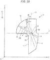
- FIG. 20 describes the imaginary line P specified in the lens.
- a projection-type image display apparatus 1B according to the present embodiment differs from the projection-type image display apparatus 1A according to Embodiment 1 in terms of the angle by which the imaginary line P inclines with respect to the imaginary vertical line V but is the same as the projection-type image display apparatus 1A according to Embodiment 1 in terms of the other configurations.
- the components corresponding to those of the projection-type image display apparatus 1A according to Embodiment 1 therefore have the same reference characters.
- the imaginary line P inclines with respect to the imaginary vertical line V, which is perpendicular to the imaginary axis L in the plane YZ.
- the imaginary axis L which is the optical axis, passes through the center of the imaginary line P.
- the imaginary line P is therefore the pupil in the plane YZ.
- the pupil inclines with respect to the imaginary vertical line V.
- the imaginary line P is perpendicular to the imaginary axis L. That is, the pupil is perpendicular to the design reference axis.
- the lower-end light flux 22 is blocked.
- the lower-end light flux 22 passing through the lower end of the effective range 20 of the second transmissive surface 13 is not blocked and reaches the screen S.
- the lens 3 according to the present embodiment satisfies the conditional expression (1), a decrease of brightness at the upper periphery of the screen S can be suppressed, as compared with the case where the imaginary line P is parallel to the imaginary vertical line V. That is, when the pupil inclines with respect to the imaginary vertical line V, which is perpendicular to the imaginary line P, the divergence angle ⁇ 0 of each of the light fluxes that reach the upper portion of the screen S increases. The amount of light that reaches the upper portion of the screen S therefore increases.
- the imaginary line P inclines by 100° with respect to the imaginary vertical line V, which is perpendicular to the imaginary axis L in the plane YZ.
- the imaginary axis L which is the optical axis, passes through the center of the imaginary line P.
- the imaginary line P is therefore the pupil in the plane YZ.
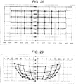
- FIG. 28 shows a distortion lattice on the screen S.
- FIG. 29 shows the distortion lattice in the demagnifying-side image formation plane of the lens 3.
- the distortion lattice in the demagnifying-side image formation plane of the lens 3 is distorted but has no field curvature.
- the image formation section 2 forms a projection image that is an inverted final image turned upside down in the demagnifying-side image formation plane.
- the image formation section 2 forms an image distorted in advance in the demagnifying-side image formation plane of the lens 3 so that an oblong projection image is projected on the screen S, which is the magnifying-side image formation plane.
- the lens 3 according to the present embodiment satisfies the conditional expression (2), the divergence angle ⁇ 0 of the light flux F1, which reaches the lower portion of the screen S decreases.
- the difference in the divergence angle ⁇ 0 between the light fluxes that reach the upper portion of the screen S and the light fluxes that reach the lower portion of the screen S therefore decreases, whereby the difference in the amount of light between the upper portion and the lower portion of the screen S can be suppressed.
- Reference character R denotes the divergence angle ratio.
- the divergence angle ratio is the proportion assuming that the divergence angle of the light flux F2, which has the highest divergence angle, is 100%.
- the divergence angle ⁇ 0 of the light flux F2 which reaches the fourth highest image height position, is greater than those of the other light fluxes F1 to F3 and F5.
- the divergence angle ⁇ 0 of the light flux F5, which reaches the highest image height position, is 63% of the divergence angle ⁇ 0 of the light flux F2.
- the divergence angle ⁇ 0 of the light flux F4, which reaches the second highest image height position, is 74% of the divergence angle ⁇ 0 of the light flux F2.
- the divergence angle ⁇ 0 of the light flux F3, which reaches the third highest image height position, is 88% of the divergence angle ⁇ 0 of the light flux F2.
- the divergence angle ⁇ 0 of the light flux F5, which reaches the lowest image height position, is 91% of the divergence angle ⁇ 0 of the light flux F2.
- the light fluxes F3, F4, and F5, which reach the upper portion of the screen S each have a large divergence angle ⁇ 0.
- the amount of light of the light fluxes that reach the upper portion of the screen S therefore increases.
- the difference in the divergence angle ⁇ 0 between the light fluxes F4 and F5, which reach the upper portion of the screen S, and the light flux F1, which reaches the lower portion of the screen S is relatively small. The difference in the amount of light between the upper portion and the lower portion of the screen S can therefore be suppressed.
- the projection-type image display apparatus 1D includes the image formation section 2 and the lens 3, as shown in FIG. 32 .
- the image formation section 2 is disposed on the demagnifying side of the lens 3.
- the image formation section 2 is a display.
- the display for example, includes a light source apparatus and a light modulator.
- the light modulator includes the liquid crystal light valve 4.
- the lens 3 is made of resin.
- the lens 3 has the first transmissive surface 11, the reflective surface 12, and the second transmissive surface 13 sequentially arranged from the demagnifying side toward the magnifying side, as shown in FIG. 33 .
- the liquid crystal light valve 4 is attached to the first transmissive surface 11.
- the upper and lower halves of the lens 3 are configured to be rotationally symmetric with respect to the imaginary axis L. That is, the first transmissive surface 11, the reflective surface 12, and the second transmissive surface 13 are so shaped that the cross-sectional shape in the plane YZ shown in FIG. 33 is rotated around the imaginary axis L over the angular range of 90° toward one side and the other side of the axis-X direction.
- the lens 3 according to the present embodiment satisfies the conditional expression (1), a decrease of brightness at the upper periphery of the screen S can be suppressed, as compared with the case where the imaginary line P is parallel to the imaginary vertical line V. That is, when the pupil inclines with respect to the imaginary vertical line V, which is perpendicular to the imaginary line P, the divergence angle ⁇ 0 of each of the light fluxes that reach the upper portion of the screen S increases. The amount of light that reaches the upper portion of the screen S therefore increases.
- the lens 3 according to the present embodiment satisfies the conditional expression (2), the divergence angle ⁇ 0 of the light flux F1, which reaches the lower portion of the screen S decreases.
- the difference in the divergence angle ⁇ 0 between the light fluxes that reach the upper portion of the screen S and the light fluxes that reach the lower portion of the screen S therefore decreases, whereby the difference in the amount of light between the upper portion and the lower portion of the screen S can be suppressed.
- the angle ⁇ 1 is the angle of the lower peripheral light ray of each of the light fluxes F1 to F5 and is the angle at which the lower peripheral light ray of each of the light fluxes F1 to F5 intersects the screen S.
- the angle ⁇ 2 is the angle of the upper peripheral light ray of each of the light fluxes F1 to F5 and is the angle at which the upper peripheral light ray of each of the light fluxes F1 to F5 intersects the screen S.
- the angle ⁇ 0 is the divergence angle and is the difference between ⁇ 2 and ⁇ 1.
- the surface number 1 is a free-form surface and is an XY polynomial surface. Since the decenter of the surface number 1 is effective on the surface number 2, the decenter & return ⁇ of the second surface is -21.4981°. That is, the pupil inclines by -21.4981° with respect to the imaginary vertical line V, which is perpendicular to the imaginary axis L in the plane YZ.
- the surface number 3 is a free-form surface and is an XY polynomial surface.
- the surface number 4 is a planar surface.
- the XY polynomial coefficients of the surface number 1 are as follows. Conic constant 2.241006E+02 X 0 Y 0 X**2 4.712531E-02 X * Y 0 Y**2 -6.69858E-02 X**3 0 X**2 * Y -1.731672E-02 X Y**2 0 Y**3 1.203742E-02 X**4 -7.823583E-05 X**3 * Y 0 X**2 * Y**2 4.753037E-03 X * Y**3 0 Y**4 2.463375E-04 X**5 0 X**4 * Y 3.456907E-04 X**3 * Y**2 0 X**2 * Y**3 -4.602323E-05 X * Y**4 0 Y**5 -4.879982E-06 X**6 -1.886499E-06 X**5 * Y
- the imaginary line P inclines by 21.4981° with respect to the imaginary vertical line V.
- the angle ⁇ 1 is the angle of the lower peripheral light ray of each of the light fluxes F1 to F5 and is the angle at which the lower peripheral light ray of each of the light fluxes F1 to F5 intersects the screen S.
- the angle ⁇ 2 is the angle of the upper peripheral light ray of each of the light fluxes F1 to F5 and is the angle at which the upper peripheral light ray of each of the light fluxes F1 to F5 intersects the screen S.
- the angle ⁇ 0 is the divergence angle and is the difference between ⁇ 2 and ⁇ 1.
- Reference character R denotes the divergence angle ratio.
- the divergence angle ratio is the proportion assuming that the divergence angle of the light flux F2, which has the highest divergence angle, is 100%.
- the divergence angle ⁇ 0 of the light flux F2 which reaches the fourth highest image height position is 56% of the divergence angle ⁇ 0 of the light flux F1, which reaches the lowest image height position.
- These values are greater than those when the imaginary line P is perpendicular to the imaginary axis L, that is, as compared with the values in the projection-type image display apparatus 100 according to Comparative Embodiment. The amount of light of the light fluxes that reach the upper portion of the screen S therefore increases.
- the lens 3 is made of resin.
- the lens 3 can instead be made of glass.
- the lens 3 can be processed with high precision as compared with the case where the lens 3 is made of resin.
- the amount of expansion of the lens 3 can be suppressed when the temperature of the lens 3 rises due to internal absorption of light, as compared with the case where the lens 3 is made of resin.
- a lens made of glass can therefore maintain the optical performance of the lens and improve the reliability thereof even when the high luminance light is incident to the lens 3.
Landscapes
- Physics & Mathematics (AREA)
- General Physics & Mathematics (AREA)
- Optics & Photonics (AREA)
- Engineering & Computer Science (AREA)
- Multimedia (AREA)
- Signal Processing (AREA)
- Lenses (AREA)
- Projection Apparatus (AREA)
Abstract
Description
- The present application is based on, and claims priority from
JP Application Serial Number 2018-141033, filed July 27, 2018 - The present disclosure relates to a lens having a concave reflective surface between two transmissive surfaces, and to a projection-type image display apparatus including the lens.
-
JP-A-2017-156713 JP-A-2017-156713 -
JP-A-2017-156713 - The optical system described in
JP-A-2017-156713 - An advantage of some aspects of the present disclosure is to provide a lens capable of suppressing a decrease in the amount of light at the upper periphery of a magnifying-side image formation plane. Another advantage of some aspects of the present disclosure is to provide a projection-type image display apparatus including the lens.
- A lens according to an aspect of the present disclosure has a first transmissive surface, a reflective surface, and a second transmissive surface sequentially arranged from a demagnifying side toward a magnifying side. Three axes perpendicular to one another are called axes X, Y, and Z, with an axis-Z direction being a direction in which the first transmissive surface and the reflective surface are arranged, an upper side being one side of the axis Y, a lower side being another side of the axis Y, and a plane YZ being a plane perpendicular to the axis X and containing the axes Y and Z. The first transmissive surface and the reflective surface are located at the lower side of an imaginary axis extending in the axis-Z direction. The second transmissive surface is located at the upper side of the imaginary axis. The reflective surface has a concave shape. The second transmissive surface has a convex shape protruding toward the magnifying side. An imaginary line that connects an upper intersection to a lower intersection inclines with respect to an imaginary vertical line perpendicular to the imaginary axis in the plane YZ, the upper intersection being an intersection where an upper peripheral light ray of an upper-end light flux that is a light ray passing through an axis-Y-direction upper end of an effective range of the second transmissive surface and an upper peripheral light ray of a lower-end light flux that is a light ray passing through an axis-Y-direction lower end of the effective range intersect with each other in the plane YZ, and the lower intersection being an intersection where a lower peripheral light ray of the upper-end light flux and a lower peripheral light ray of the lower-end light flux intersect with each other in the plane YZ.
- In the aspect of the present disclosure, the first transmissive surface, the reflective surface, and the second transmissive surface may form a coaxial optical system having surfaces rotationally symmetric with respect to the imaginary axis, and the imaginary axis may be a design reference axis.
- In the aspect of the present disclosure, the lens may satisfy a conditional expression below:

- In the aspect of the present disclosure, the lens may satisfy a conditional expression (2) below:

- In the aspect of the present disclosure, any of the first transmissive surface, the reflective surface, and the second transmissive surface may be an aspheric surface.
- In the aspect of the present disclosure, the lens may further include a light blocker that blocks light rays that incline with respect to the imaginary line and do not fall within the effective range through which the imaginary line passes.
- In the aspect of the present disclosure, any of the first transmissive surface, the reflective surface, and the second transmissive surface may be a free-form surface.
- A projection-type image display apparatus according to another aspect of the present disclosure includes any of the lenses described above and an image formation section that displays a projection image in a demagnifying-side image formation plane of the lens.
- A projection-type image display apparatus according to another aspect of the present disclosure includes a first optical system, a second optical system, and a display. The first optical system is any of the lenses described above. The second optical system is disposed between the first optical system and the light modulator. A projection image displayed by the display is projected via the second optical system and the first optical system.
-
-
FIG. 1 is a light ray diagram of a projection-type image display apparatus according toEmbodiment 1 of the present disclosure. -
FIG. 2 is a partially enlarged view of a portion A inFIG. 1 . -
FIG. 3 is a partially enlarged view of a portion B inFIG. 1 . -
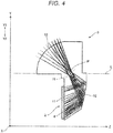
FIG. 4 is a light ray diagram showing light rays passing through a lens in the projection-type image display apparatus inFIG. 1 . -
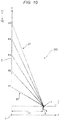
FIG. 5 describes an imaginary line specified in the lens inFIG. 4 . -
FIG. 6 shows a distortion lattice on a screen. -
FIG. 7 shows a distortion lattice in the demagnifying-side image formation plane of the lens. -
FIG. 8 shows an MTF of the lens on the demagnifying side. -
FIG. 9 is a spot diagram showing spots produced by the lens. -
FIG. 10 is a light ray diagram of a projection-type image display apparatus according to Comparative Embodiment. -
FIG. 11 is a light ray diagram showing light rays passing through a lens in the projection-type image display apparatus according to Comparative Embodiment. -
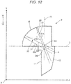
FIG. 12 describes an imaginary line specified in the lens inFIG. 11 . -
FIG. 13 shows a distortion lattice on the screen. -
FIG. 14 shows a distortion lattice in the demagnifying-side image formation plane of the lens. -
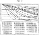
FIG. 15 shows an MTF of the lens according to Comparative Embodiment on the demagnifying side. -
FIG. 16 is a spot diagram showing spots produced by the lens according to Comparative Embodiment. -
FIG. 17 shows graphs that compare a divergence angle of each light flux betweenEmbodiment 1 and Comparative Embodiment. -
FIG. 18 is a light ray diagram of a projection-type image display apparatus according toEmbodiment 2. -
FIG. 19 is a light ray diagram showing light rays passing through a lens in the projection-type image display apparatus according toEmbodiment 2. -
FIG. 20 describes an imaginary line specified in the lens inFIG. 19 . -
FIG. 21 shows a distortion lattice on the screen. -
FIG. 22 shows a distortion lattice in the demagnifying-side image formation plane of the lens. -
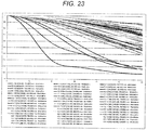
FIG. 23 shows an MTF of the lens according toEmbodiment 2 on the demagnifying side. -
FIG. 24 is a spot diagram showing spots produced by the lens according to Embodiment 2. -
FIG. 25 is a light ray diagram of a projection-type image display apparatus according toEmbodiment 3. -
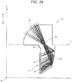
FIG. 26 is a light ray diagram showing light rays passing through a lens in the projection-type image display apparatus according toEmbodiment 3. -
FIG. 27 describes an imaginary line specified in the lens inFIG. 26 . -
FIG. 28 shows a distortion lattice on the screen. -
FIG. 29 shows a distortion lattice in the demagnifying-side image formation plane of the lens. -
FIG. 30 shows an MTF of the lens according toEmbodiment 3 on the demagnifying side. -
FIG. 31 is a spot diagram showing spots produced by the lens according toEmbodiment 3. -
FIG. 32 is a light ray diagram of a projection-type image display apparatus according toEmbodiment 4. -
FIG. 33 is a light ray diagram showing light rays passing through a lens in the projection-type image display apparatus according toEmbodiment 4. -
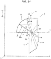
FIG. 34 describes an imaginary line specified in the lens inFIG. 33 . -
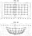
FIG. 35 shows a distortion lattice on the screen. -
FIG. 36 shows a distortion lattice in the demagnifying-side image formation plane of the lens. -
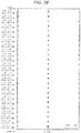
FIG. 37 shows an MTF of the lens according toEmbodiment 4 on the demagnifying side. -
FIG. 38 is a spot diagram showing spots produced by the lens according toEmbodiment 4. -
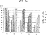
FIG. 39 shows graphs that compare the divergence angle of each light flux betweenEmbodiments 1 to 4 and Comparative Embodiment. -
FIG. 40 is a light ray diagram of a projection-type image display apparatus according to Embodiment 5. -
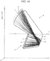
FIG. 41 is a light ray diagram showing light rays passing through a lens in the projection-type image display apparatus according to Embodiment 5. -
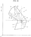
FIG. 42 describes an imaginary line specified in the lens inFIG. 41 . -
FIG. 43 shows a distortion lattice on the screen. -
FIG. 44 shows a distortion lattice in the demagnifying-side image formation plane of the lens. -
FIG. 45 shows an MTF of the lens according to Embodiment 5 on the demagnifying side. -
FIG. 46 is a spot diagram showing spots produced by the lens according to Embodiment 5. -
FIG. 47 describes a projection-type image display apparatus according to a variation. - A lens and a projection-type image display apparatus including the lens according to an embodiment of the present disclosure will be described below in detail with reference to the drawings.
-
FIG. 1 is a light ray diagram of a projection-type image display apparatus according toEmbodiment 1 of the present disclosure.FIG. 2 is a partially enlarged view of a portion A inFIG. 1 . The portion A is a portion of a screen that is the portion where the image height is maximized in the direction along an axis Y and therearound.FIG. 3 is a partially enlarged view of a portion B inFIG. 1 . The portion B is a portion of the screen that is the portion where the image height is minimized in the direction along the axis Y and therearound.FIG. 4 is a light ray diagram showing light rays passing through a lens in the projection-type image display apparatus inFIG. 1 .FIG. 5 describes an imaginary line specified in the lens. - A projection-type
image display apparatus 1A according to the present embodiment includes animage formation section 2 and alens 3, as shown inFIG. 1 . Theimage formation section 2 forms a projection image in the demagnifying-side image formation plane of thelens 3. A screen S is disposed in the magnifying-side image formation plane of thelens 3. In other words, the screen S is the magnifying-side image formation plane of thelens 3. - The
image formation section 2 is a display. The display, for example, includes a light source apparatus and a light modulator. In the present embodiment, the light modulator is a liquid crystallight valve 4. The liquid crystallight valve 4 includes a liquid crystal panel, a light-incident-side polarizer, and a light-exiting-side polarizer. The liquid crystallight valve 4 modulates the spatial distribution of the light intensity incident from the light source apparatus on a pixel basis to form the projection image. InFIGS. 1 and4 , the liquid crystallight valve 4 is shown as theimage formation section 2. - The
lens 3 is made of resin. Thelens 3 has afirst transmissive surface 11, areflective surface 12, and asecond transmissive surface 13 sequentially arranged from the demagnifying side toward the magnifying side, as shown inFIG. 4 . In the case where thelens 3 is made of resin, thelens 3 can be manufactured in injection molding. A lens having a complicated shape, such as a free-form surface, is therefore readily manufactured. - The liquid crystal
light valve 4 is attached to thefirst transmissive surface 11. The projection image displayed on the liquid crystallight valve 4 is projected on the screen S via thefirst transmissive surface 11, thereflective surface 12, and thesecond transmissive surface 13 in the present order. The final image projected on the screen S has an oblong shape elongated in the lateral direction. In the present embodiment, the final image has an aspect ratio of 16:10. - In the following description, three axes perpendicular to one another are called axes X, Y, and Z. A first direction in which the
first transmissive surface 11 and thereflective surface 12 are arranged is called an axis-Z direction. A second direction, which is called an axis-y direction, coincides with the vertical direction of the screen S. One side of the axis Y is called an upper side Y1, and the other side of the axis Y is called a lower side Y2. A first plane perpendicular to the axis X and containing the axes Y and Z is called a plane YZ.FIGS. 1 to 5 each show the plane YZ. The lateral direction of the screen S coincides with a third direction, which is called the axis-X direction. In the following description, an imaginary axis L extending in the axis-Z direction is set in the plane YZ. In the present embodiment, the imaginary axis L is a reference axis used in the design of thelens 3. The imaginary axis L is perpendicular to the screen S, which is the magnifying-side image formation plane. The imaginary axis L is substantially perpendicular to the screen S in some cases. - The
first transmissive surface 11 and thereflective surface 12 are located at the lower side Y2 of the imaginary axis L. Thesecond transmissive surface 13 is located at the upper side Y1 of the imaginary axis L. Thereflective surface 12 has a concave shape. Thereflective surface 12 is provided by externally forming a reflective coating on thelens 3. Thesecond transmissive surface 13 has a convex shape protruding toward the magnifying side. - In the present embodiment, the
first transmissive surface 11, thereflective surface 12, and thesecond transmissive surface 13 form a coaxial optical system. Therefore, the imaginary axis L is the reference axis used in the design of thelens 3 and is the optical axis of thelens 3. The upper and lower halves of thelens 3 are configured to be rotationally symmetric with respect to the imaginary axis L. That is, thefirst transmissive surface 11, thereflective surface 12, and thesecond transmissive surface 13 are so shaped that the cross-sectional shape in the plane YZ shown inFIG. 4 is rotated around the imaginary axis L over an angular range of 90° toward one side and the other side of the axis-X direction. - An imaginary line P can be specified in the
lens 3, as shown inFIG. 5 . The imaginary line P connects anupper intersection 23 to alower intersection 24, theupper intersection 23 being an intersection where an upper peripherallight ray 21a of an upper-end light flux 21, where the upper-end light flux 21 is the light flux passing through the axis-Y-direction upper end of aneffective range 20 of thesecond transmissive surface 13, and an upper peripherallight ray 22a of a lower-end light flux 22, where the lower-end light flux 22 is the light flux passing through the axis-Y-direction lower end of theeffective range 20, intersect with each other in the plane YZ, and thelower intersection 24 being an intersection where a lower peripherallight ray 21b of the upper-end light flux 21 and a lower peripherallight ray 22b of the lower-end light flux 22 intersect with each other in the plane YZ. The imaginary line P inclines by 45° with respect to an imaginary vertical line V, which is perpendicular to the imaginary axis L in the plane YZ. In the present embodiment, the imaginary axis L, which is the optical axis, passes through the center of the imaginary line P. The imaginary line P is therefore the pupil in the plane YZ. In the present specification, also when the optical axis does not pass through the center of the imaginary line P, the imaginary line P, which connects theupper intersection 23 and thelower intersection 24 to each other in the plane YZ, is referred to as a "pupil." - Lens data on the
lens 3 are as follows: In the lens data, thesurface number 1 is thesecond transmissive surface 13 and is a refractive surface. Thesurface number 2 is the pupil. Thesurface number 3 is thereflective surface 12. Thesurface number 4 is thefirst transmissive surface 11 and is a refractive surface. Reference character r denotes the radius of curvature in millimeters. Reference character d denotes the on-axis inter-surface distance in millimeters. Reference character nd denotes the refractive index. Reference character vd denotes the Abbe number. Reference character Y denotes the effective radius in the axis-Y direction. Reference character X denotes the effective radius in the axis-X direction.Surface number Surface type r d nd νd Y X Object plane Spherical 0 295 1 Aspheric 15 10 1.531132 55.75 9.35 9.35 2 Spherical 0 5 1.531132 55.75 0.65 1 3 Aspheric -11 -6.7503 1.531132 55.75 10.368 10.368 4 (Image plane) Spherical 0 0 1.531132 55.75 13.754 13.754 - The refractive index nd of the
lens 3 is 1.531132. The Abbe number vd of thelens 3 is 55.75. The on-axis inter-surface distance d in the field of the object plane is the distance between the screen S and thesurface number 1. The on-axis inter-surface distance d in the field of the object plane is therefore a projection distance f of the projection-typeimage display apparatus 1A. In the present embodiment, f=295 mm. - In the present embodiment, the
surface number 1 is an aspheric surface. The decenter & return α of thesurface number 2 is -45°. That is, the pupil inclines by 45° with respect to the imaginary vertical line V, which is perpendicular to the optical axis in the plane YZ. Thesurface number 3 is an aspheric surface. Thesurface number 4 is a spherical surface. - Aspheric data of the
surface number 1 are as follows.Conic constant 1.191933E+00 Fourth-order coefficient 8.185879E-04 Sixth-order coefficient -1.185338E-05 Eighth-order coefficient 1.057894E-07 Tenth-order coefficient -2.762786E-10 - Aspheric data of the
surface number 3 are as follows.Conic constant -1.114283E+02 Fourth-order coefficient -1.612935E-04 Sixth-order coefficient 1.601981E-06 Eighth-order coefficient -9.655743E-09 Tenth-order coefficient 2.369119E-11 - The projection image formed by the
image formation section 2 will next be described.FIG. 6 shows a distortion lattice on the screen S.FIG. 7 shows the distortion lattice in the demagnifying-side image formation plane of thelens 3. The distortion lattice in the demagnifying-side image formation plane is distorted but has no field curvature. - The
image formation section 2 forms a projection image that is an inverted final image turned upside down in the demagnifying-side image formation plane. Theimage formation section 2 forms an image distorted in advance in the demagnifying-side image formation plane of thelens 3 so that an oblong projection image is projected on the screen S, which is the magnifying-side image formation plane. More specifically, theimage formation section 2 forms a distorted projection image corresponding to the distortion lattice shown inFIG. 7 in the demagnifying-side image formation plane so that a final image corresponding to the distortion lattice shown inFIG. 6 is projected on the screen S. The projection image has a shape reducing the trapezoidal distortion of the final image formed on the screen S. That is, the projection image has distortion opposite the trapezoidal distortion of the final image. The projection image is therefore so formed that the shortest edge thereof is the edge having the highest image height on the screen S. - In the present embodiment, the
reflective surface 12 and thesecond transmissive surface 13 are each an aspheric surface. The amount of aberrations produced by the lens can therefore be suppressed.FIG. 8 shows an MTF of thelens 3 on the demagnifying side. The MTF was calculated under the following conditions: The image formation planes were divided along the axis Y; and the resultant halves were each divided into 25 areas. Light rays used in the calculation of the MTF are so weighted that the weighting ratio among light rays having a wavelength of 620 nm, light rays having a wavelength of 550 nm, and light rays having a wavelength of 470 nm is 2:7:1. The horizontal axis ofFIG. 8 , which shows the MTF, represents the spatial frequency. A spatial frequency of 30 cycles corresponds to a resolution of 16.7 µm. The vertical axis ofFIG. 8 represents a contrast reproduction ratio. In the present embodiment,FIG. 8 shows that the resolution decreases on the side close to the optical axis. Decrease in the resolution in the other area is, however, suppressed. -
FIG. 9 is a spot diagram showing spots produced by thelens 3. The spot diagram shown inFIG. 9 shows that the size of the spot increases in lower image height positions on the screen S. Portions of the projection image that is the portions projected in the lower image height positions on the screen S are, however, the portions each having a large lattice interval of the distortion lattice in the demagnifying-side image formation plane of the lens shown inFIG. 7 . Theimage formation section 2 can therefore express each of the image portions projected in the lower image height positions on the screen S by using a greater number of pixels. The projection-typeimage display apparatus 1A according to the present embodiment can therefore suppress a decrease in the resolution of the final image at the locations where the spot diagram shows large spots, that is, in the lower image height positions on the screen S. - The
lens 3 according to the present embodiment satisfies the following conditional expression (1).
- θ: Inclination angle over which an end of the imaginary line P facing the
upper intersection 23 rotates counterclockwise relative to the imaginary vertical line V around the intersection of the imaginary vertical line V and the imaginary line P - γ: angle from the imaginary axis L to the lower peripheral
light ray 22b passing through theeffective range 20 of thesecond transmissive surface 13 and intersects the imaginary axis L. - That is, in the present embodiment, the imaginary line P inclines by 45° with respect to the imaginary vertical line V. In other words, in the present embodiment, the pupil inclines by 45° with respect to the imaginary vertical line V. Therefore, θ=45°, which satisfies the conditional expression (1).
- In the present embodiment, in which the conditional expression (1) is satisfied, the pupil inclines with respect to the imaginary vertical line V. In a case where θ=0° in the conditional expression (1), the imaginary line P is perpendicular to the imaginary axis L. That is, the pupil is perpendicular to the design reference axis. In a case where θ is greater than the upper limit in the conditional expression (1), the lower-
end light flux 22 is blocked. In the present embodiment, in which the conditional expression (1) is satisfied, the lower-end light flux 22 passing through the lower end of theeffective range 20 of thesecond transmissive surface 13 is not blocked and reaches the screen S. - Further, since the
lens 3 according to the present embodiment satisfies the conditional expression (1), a decrease of brightness at the upper periphery of the screen S can be suppressed, as compared with a case where the imaginary line P is parallel to the imaginary vertical line V. - That is, when the pupil is perpendicular to the imaginary axis L, a divergence angle θ0 of a light flux that reaches an upper portion of the screen S decreases as the angle of view on the magnifying side increases . The divergence angle θ0 is shown in
FIGS. 2 and3 . In the case where the pupil is perpendicular to the imaginary axis L, the difference in the divergence angle θ0 between the light flux that reaches the upper portion of the screen S and a light flux that reaches a lower portion of the screen S increases as the angle of view on the magnifying side increases. As a result, the amount of light at the upper periphery of the screen S is smaller than the amount of light at the lower periphery of the screen S. - On the other hand, in the present embodiment, in which the conditional expression (1) is satisfied, the pupil inclines with respect to the imaginary vertical line V, which is perpendicular to the imaginary line P. As a result, the divergence angle θ0 of the light flux that reaches the upper portion of the screen S increases. The amount of light that reaches the upper portion of the screen S therefore increases. Further, when the divergence angle θ0 of the light flux that reaches the upper portion of the screen S increases, the difference in the divergence angle θ0 between the light flux that reaches the upper portion of the image formation plane and the light flux that reaches the lower portion of the image formation plane decreases. The situation in which the amount of light at the upper periphery of the screen S is smaller than the amount of light at the lower periphery of the screen S can therefore be suppressed.
- Data on the divergence angle θ0 of each of light fluxes F1 to F5, which reach corresponding image heights on the screen S, are shown below. The light flux F1 is a light flux that reaches the lowest image height position, as shown in
FIG. 1 . The light flux F5 is a light flux that reaches the highest image height position. The light fluxes F2 to F4 are light fluxes that reach height positions between the height position that the light flux F1 reaches and the height position that the light flux F5 reaches. Assuming that the coordinate of the light flux F1 on the axis Y is 180 in the plane YZ and the coordinate of the light flux F5 on the axis Y is 780 in the plane YZ, and the coordinate of the light flux F2 on the axis Y is 330 and the coordinate of the light flux F3 on the axis Y is 480. The coordinate of the light flux F4 on the axis Y is 630. An angle θ1 is the angle of the lower peripheral light ray of each of the light fluxes F1 to F5 and is the angle at which the lower peripheral light ray of each of the light fluxes F1 to F5 intersects the screen S, as shown inFIGS. 2 and3 . An angle θ2 is the angle of the upper peripheral light ray of each of the light fluxes F1 to F5 and is the angle at which the upper peripheral light ray of each of the light fluxes F1 to F5 intersects the screen S, as shown inFIGS. 2 and3 . The angle θ0 is the divergence angle and is the difference between θ2 and θ1. Reference character R denotes a divergence angle ratio. The divergence angle ratio is the proportion assuming that the divergence angle of the light flux F1, which has the highest divergence angle, is 100%. - Data on the divergence angle θ0 of each of the light fluxes F1 to F5, which reach the corresponding image heights on the screen S, are as follows.
Light flux θ1 θ2 θ0 R F1 30.33 30.68 0.35 100% F2 47.09 47.33 0.24 69% F3 57.46 57.63 0.17 49% F4 64.09 64.23 0.13 37% F5 68.59 68.70 0.10 30% - In the present embodiment, the divergence angle θ0 of the light flux F5, which reaches the highest image height position, is 30% of the divergence angle θ0 of the light flux F1, which reaches the lowest image height position. The divergence angle θ0 of the light flux F4, which reaches the second highest image height position, is 37% of the divergence angle θ0 of the light flux F1, which reaches the lowest image height position. The divergence angle θ0 of the light flux F3, which reaches the third highest image height position, is 49% of the divergence angle θ0 of the light flux F1, which reaches the lowest image height position. The divergence angle θ0 of the light flux F4, which reaches the fourth highest image height position, is 69% of the divergence angle θ0 of the light flux F1, which reaches the lowest image height position. These values are greater than those when the imaginary line P is perpendicular to the imaginary axis L, as shown below.
- A more detailed description will next be made of the fact that
Embodiment 1 can provide the effect of suppressing a decrease of brightness at the upper periphery of the screen S with reference to Comparative Embodiment.FIG. 10 is a light ray diagram of a projection-type image display apparatus according to Comparative Embodiment.FIG. 11 is a light ray diagram showing light rays passing through a lens in the projection-type image display apparatus according to Comparative Embodiment.FIG. 12 describes an imaginary line specified in the lens. A projection-typeimage display apparatus 100 according to the present embodiment has the same configuration as that of the projection-typeimage display apparatus 1A according toEmbodiment 1 except that the imaginary line P is perpendicular to the imaginary axis L. The corresponding components therefore have the same reference characters. - The projection-type
image display apparatus 100 according to the present embodiment includes theimage formation section 2 and thelens 3, as shown inFIG. 10 . Theimage formation section 2 is disposed on the demagnifying side of thelens 3. Theimage formation section 2 is a display. The display, for example, includes a light source apparatus and a light modulator. The light modulator includes the liquid crystallight valve 4. Thelens 3 is made of resin. Thelens 3 has thefirst transmissive surface 11, thereflective surface 12, and thesecond transmissive surface 13 sequentially arranged from the demagnifying side toward the magnifying side, as shown inFIG. 11 . The liquid crystallight valve 4 is attached to thefirst transmissive surface 11. The projection image displayed on the liquid crystallight valve 4 is projected on the screen S via thefirst transmissive surface 11, thereflective surface 12, and thesecond transmissive surface 13 in the present order. The final image projected on the screen S has an oblong shape elongated in the lateral direction. The final image has the aspect ratio of 16:10. Also in the present embodiment, the imaginary axis L extending in the axis-Z direction is set in the plane YZ. The imaginary axis L is the reference axis used in the design of the lens. - The
first transmissive surface 11 and thereflective surface 12 are located at the lower side Y2 of the imaginary axis L. Thesecond transmissive surface 13 is located at the upper side Y1 of the imaginary axis L. Thereflective surface 12 has a concave shape. Thereflective surface 12 is provided by externally forming a reflective coating on thelens 3. Thesecond transmissive surface 13 has a convex shape protruding toward the magnifying side. Thefirst transmissive surface 11, thereflective surface 12, and thesecond transmissive surface 13 form a coaxial optical system. Therefore, the imaginary axis L is the reference axis used in the design of thelens 3 and is the optical axis of thelens 3. The upper and lower halves of thelens 3 are configured to be rotationally symmetric with respect to the imaginary axis L. That is, thefirst transmissive surface 11, thereflective surface 12, and thesecond transmissive surface 13 are so shaped that the cross-sectional shape in the plane YZ shown inFIG. 11 is rotated around the imaginary axis L over the angular range of 90° toward one side and the other side of the axis-X direction. - The imaginary line P can be specified in the
lens 3, as shown inFIG. 12 . The imaginary line P connects theupper intersection 23 to thelower intersection 24, theupper intersection 23 being an intersection where the upper peripherallight ray 21a of the upper-end light flux 21, where the upper-end light flux 21 is the light flux passing through the axis-Y-direction upper end of theeffective range 20 of thesecond transmissive surface 13, and the upper peripherallight ray 22a of the lower-end light flux 22, where the lower-end light flux 22 is the light flux passing through the axis-Y-direction lower end of theeffective range 20, intersect with each other in the plane YZ, and thelower intersection 24 being an intersection where the lower peripherallight ray 21b of the upper-end light flux 21 and the lower peripherallight ray 22b of the lower-end light flux 22 intersect with each other in the plane YZ. The imaginary line P is parallel to the imaginary vertical line V, which is perpendicular to the imaginary axis L in the plane YZ. In the present embodiment, the imaginary axis L, which is the optical axis, passes through the center of the imaginary line P. The imaginary line P is therefore the pupil in the plane YZ. - Lens data on the
lens 3 according to Comparative Embodiment are as follows: In the lens data, thesurface number 1 is thesecond transmissive surface 13 and is a refractive surface. Thesurface number 2 is the pupil. Thesurface number 3 is thereflective surface 12. Thesurface number 4 is thefirst transmissive surface 11 and is a refractive surface. Reference character r denotes the radius of curvature in millimeters. Reference character d denotes the on-axis inter-surface distance in millimeters. Reference character nd denotes the refractive index. Reference character vd denotes the Abbe number. Reference character Y denotes the effective radius in the axis-Y direction. Reference character X denotes the effective radius in the axis-X direction.Surface number Surface type r d nd νd Y X Object plane Spherical 0 295 1 Aspheric 15 10 1.531132 55.75 9.019 9.019 2 Spherical 0 5 1.531132 55.75 1 1 3 Aspheric -11 -6.277 1.531132 55.75 10.558 10.558 4 (Image plane) Spherical 0 0 1.531132 55.75 13.389 13.389 - The refractive index nd of the
lens 3 is 1.531132. The Abbe number vd of thelens 3 is 55.75. The on-axis inter-surface distance d in the field of the object plane is the distance between the screen S and thesurface number 1. The on-axis inter-surface distance d in the field of the object plane is therefore the projection distance f of the projection-typeimage display apparatus 100. In the present embodiment, f=295 mm. - In the present embodiment, the
surface number 1 is an aspheric surface. The decenter & return α of thesurface number 2 is 0°. That is, the pupil does not incline with respect to the imaginary vertical line V, which is perpendicular to the optical axis in the plane YZ. Thesurface number 3 is an aspheric surface. Thesurface number 4 is a spherical surface. - Aspheric data of the
surface number 1 are as follows.Conic constant 1.597914E+00 Fourth-order coefficient 1.003949E-03 Sixth-order coefficient -1.770946E-05 Eighth-order coefficient 1.911983E-07 Tenth-order coefficient -6.508832E-10 - Aspheric data of the
surface number 3 are as follows.Conic constant -9.4411E+01 Fourth-order coefficient -1.369046E-04 Sixth-order coefficient 1.096019E-06 Eighth-order coefficient -5.971179E-09 Tenth-order coefficient 1.384487E-11 - The projection image formed by the
image formation section 2 will next be described.FIG. 13 shows a distortion lattice on the screen S.FIG. 14 shows the distortion lattice in the demagnifying-side image formation plane of thelens 3. The distortion lattice in the demagnifying-side image formation plane of thelens 3 is distorted but has no field curvature. Theimage formation section 2 forms a projection image that is an inverted final image turned upside down in the demagnifying-side image formation plane. Theimage formation section 2 forms an image distorted in advance in the demagnifying-side image formation plane of thelens 3 so that an oblong projection image is projected on the screen S, which is the magnifying-side image formation plane. That is, theimage formation section 2 forms a distorted projection image corresponding to the distortion lattice shown inFIG. 14 in the demagnifying-side image formation plane so that a final image corresponding to the distortion lattice shown inFIG. 13 is projected on the screen S. -
FIG. 15 shows an MTF of thelens 3 according to Comparative Embodiment on the demagnifying side. The MTF was calculated in the same manner in the embodiment described above.FIG. 16 is a spot diagram showing spots produced by thelens 3 according to Comparative Embodiment. - The
lens 3 according to the present embodiment does not satisfy the following conditional expression (1).
- θ: Inclination angle over which an end of the imaginary line P facing the
upper intersection 23 rotates counterclockwise relative to the imaginary vertical line V around the intersection of the imaginary vertical line V and the imaginary line P - γ: angle from the imaginary axis L to the lower peripheral
light ray 22b passing through theeffective range 20 of thesecond transmissive surface 13 and intersects the imaginary axis L. - That is, in the present embodiment, the imaginary line P is parallel to the imaginary vertical line V. In other words, in the present embodiment, the pupil is perpendicular to the imaginary axis L. Therefore, θ=0°, which does not satisfy the conditional expression (1).
- Since the conditional expression (1) is not satisfied, brightness at the upper periphery of the screen S decreases. That is, when the pupil is perpendicular to the imaginary axis L, the divergence angle θ0 of each of the light fluxes that reach the upper portion of the screen S decreases as the angle of view on the magnifying side increases. Further, the difference in the divergence angle θ0 between the light fluxes that reach the upper portion of the screen S and the light fluxes that reach the lower portion of the screen S increases. As a result, the amount of light at the upper periphery of the screen S is smaller than the amount of light at the lower periphery of the screen S.
- Data on the divergence angle θ0 of each of light fluxes F1 to F5, which reach the corresponding image heights on the screen S, are shown below. The angle θ1 is the angle of the lower peripheral light ray of each of the light fluxes F1 to F5 and is the angle at which the lower peripheral light ray of each of the light fluxes F1 to F5 intersects the screen S. The angle θ2 is the angle of the upper peripheral light ray of each of the light fluxes F1 to F5 and is the angle at which the upper peripheral light ray of each of the light fluxes F1 to F5 intersects the screen S. The angle θ0 is the divergence angle and is the difference between θ2 and θ1. Reference character R denotes the divergence angle ratio. The divergence angle ratio is the proportion assuming that the divergence angle of the light flux F1, which has the highest divergence angle, is 100%.
Light flux θ1 θ2 θ0 R F1 30.26 30.73 0.48 100% F2 47.07 47.31 0.24 51% F3 57.46 57.59 0.14 29% F4 64.10 64.19 0.09 18% F5 68.60 68.66 0.06 13% - In the present embodiment, the divergence angle θ0 of the light flux F5, which reaches the highest image height position, is 13% of the divergence angle θ0 of the light flux F1, which reaches the lowest image height position. The divergence angle θ0 of the light flux F4, which reaches the second highest image height position, is 18% of the divergence angle θ0 of the light flux F1, which reaches the lowest image height position. The divergence angle θ0 of the light flux F3, which reaches the third highest image height position, is 29% of the divergence angle θ0 of the light flux F1, which reaches the lowest image height position. The divergence angle θ0 of the light flux F4, which reaches the fourth highest image height position, is 51% of the divergence angle θ0 of the light flux F1, which reaches the lowest image height position.
-
FIG. 17 shows graphs that compare the divergence angle θ0 of each of light fluxes F1 to F5, which reach the corresponding image heights on the screen S, betweenEmbodiment 1 and Comparative Embodiment. In the projection-typeimage display apparatus 1A according toEmbodiment 1, the divergence angle θ0 of all the light rays of the light fluxes F2 to F5 is greater than the divergence angle θ0 of the light rays of the light fluxes F2 to F5 in the projection-typeimage display apparatus 100 according to Comparative Embodiment, as shown inFIG. 17 .Embodiment 1 can therefore suppress, as compared with Comparative Embodiment, the degree by which the amount of light at the upper periphery of the screen S is smaller than the amount of light at the lower periphery. - A projection-type image display apparatus according to
Embodiment 2, to which the present disclosure is applied, will next be described.FIG. 18 is a light ray diagram of the projection-type image display apparatus according toEmbodiment 2.FIG. 19 is a light ray diagram showing light rays passing through a lens in the projection-type image display apparatus according toEmbodiment 2.FIG. 20 describes the imaginary line P specified in the lens. A projection-typeimage display apparatus 1B according to the present embodiment differs from the projection-typeimage display apparatus 1A according toEmbodiment 1 in terms of the angle by which the imaginary line P inclines with respect to the imaginary vertical line V but is the same as the projection-typeimage display apparatus 1A according toEmbodiment 1 in terms of the other configurations. The components corresponding to those of the projection-typeimage display apparatus 1A according toEmbodiment 1 therefore have the same reference characters. - The projection-type
image display apparatus 1B according to the present embodiment includes theimage formation section 2 and thelens 3, as shown inFIG. 18 . Theimage formation section 2 is disposed on the demagnifying side of thelens 3. Theimage formation section 2 is a display. The display, for example, includes a light source apparatus and a light modulator. The light modulator includes the liquid crystallight valve 4. Thelens 3 is made of resin. Thelens 3 has thefirst transmissive surface 11, thereflective surface 12, and thesecond transmissive surface 13 sequentially arranged from the demagnifying side toward the magnifying side, as shown inFIG. 19 . The liquid crystallight valve 4 is attached to thefirst transmissive surface 11. The projection image displayed on the liquid crystallight valve 4 is projected on the screen S via thefirst transmissive surface 11, thereflective surface 12, and thesecond transmissive surface 13 in the present order. The final image projected on the screen S has an oblong shape elongated in the lateral direction. The final image has the aspect ratio of 16:10. Also in the present embodiment, the imaginary axis L extending in the axis-Z direction is set in the plane YZ. The imaginary axis L is the reference axis used in the design of the lens. - The
first transmissive surface 11 and thereflective surface 12 are located at the lower side Y2 of the imaginary axis L. Thesecond transmissive surface 13 is located at the upper side Y1 of the imaginary axis L. Thereflective surface 12 has a concave shape. Thereflective surface 12 is provided by externally forming a reflective coating on thelens 3. Thesecond transmissive surface 13 has a convex shape protruding toward the magnifying side. Thefirst transmissive surface 11, thereflective surface 12, and thesecond transmissive surface 13 form a coaxial optical system. Therefore, the imaginary axis L is the reference axis used in the design of thelens 3 and is the optical axis of thelens 3. The upper and lower halves of thelens 3 are configured to be rotationally symmetric with respect to the imaginary axis L. That is, thefirst transmissive surface 11, thereflective surface 12, and thesecond transmissive surface 13 are so shaped that the cross-sectional shape in the plane YZ shown inFIG. 19 is rotated around the imaginary axis L over the angular range of 90° toward one side and the other side of the axis-X direction. - The imaginary line P can be specified in the
lens 3, as shown inFIG. 20 . The imaginary line P connects theupper intersection 23 to thelower intersection 24, theupper intersection 23 being an intersection where the upper peripherallight ray 21a of the upper-end light flux 21, where the upper-end light flux 21 is the light flux passing through the axis-Y-direction upper end of theeffective range 20 of thesecond transmissive surface 13, and the upper peripherallight ray 22a of the lower-end light flux 22, where the lower-end light flux 22 is the light flux passing through the axis-Y-direction lower end of theeffective range 20, intersect with each other in the plane YZ, and thelower intersection 24 being an intersection where the lower peripherallight ray 21b of the upper-end light flux 21 and the lower peripherallight ray 22b of the lower-end light flux 22 intersect with each other in the plane YZ. The imaginary line P inclines with respect to the imaginary vertical line V, which is perpendicular to the imaginary axis L in the plane YZ. In the present embodiment, the imaginary axis L, which is the optical axis, passes through the center of the imaginary line P. The imaginary line P is therefore the pupil in the plane YZ. - Lens data on the
lens 3 according toEmbodiment 2 are as follows: In the lens data, thesurface number 1 is thesecond transmissive surface 13 and is a refractive surface. Thesurface number 2 is the pupil. Thesurface number 3 is thereflective surface 12. Thesurface number 4 is thefirst transmissive surface 11 and is a refractive surface. Reference character r denotes the radius of curvature in millimeters. Reference character d denotes the on-axis inter-surface distance in millimeters. Reference character nd denotes the refractive index. Reference character vd denotes the Abbe number. Reference character Y denotes the effective radius in the axis-Y direction. Reference character X denotes the effective radius in the axis-X direction.Surface number Surface type r d nd νd Y X Object plane Spherical 0 295 1 Aspheric 15 10 1.531132 55.75 9.298 9.298 2 Spherical 0 5 1.531132 55.75 0.65 1 3 Aspheric -11 -6.7085 1.531132 55.75 10.326 10.326 4 (Image plane) Spherical 0 0 1.531132 55.75 13.715 13.715 - The refractive index nd of the
lens 3 is 1.531132. The Abbe number vd of thelens 3 is 55.75. The on-axis inter-surface distance d in the field of the object plane is the distance between the screen S and thesurface number 1. The on-axis inter-surface distance d in the field of the object plane is therefore the projection distance f of the projection-typeimage display apparatus 1B. In the present embodiment, f=295 mm. - In the present embodiment, the
surface number 1 is an aspheric surface. The decenter & return α of thesurface number 2 is -90°. That is, the pupil inclines with respect to the imaginary vertical line V, which is perpendicular to the optical axis in the plane YZ, and is parallel to the imaginary axis L. Thesurface number 3 is an aspheric surface. Thesurface number 4 is a spherical surface. - Aspheric data of the
surface number 1 are as follows.Conic constant 1.15204E+00 Fourth-order coefficient 8.342038E-04 Sixth-order coefficient -1.131847E-05 Eighth-order coefficient 9.347004E-08 Tenth-order coefficient -1.983545E-10 - Aspheric data of the
surface number 3 are as follows:Conic constant -1.267929E+02 Fourth-order coefficient -1.683019E-04 Sixth-order coefficient 1.672023E-06 Eighth-order coefficient -9.961324E-09 Tenth-order coefficient 2.404807E-11 - The projection image formed by the
image formation section 2 will next be described.FIG. 21 shows a distortion lattice on the screen S.FIG. 22 shows the distortion lattice in the demagnifying-side image formation plane of thelens 3. The distortion lattice in the demagnifying-side image formation plane of thelens 3 is distorted but has no field curvature. Theimage formation section 2 forms a projection image that is an inverted final image turned upside down in the demagnifying-side image formation plane. Theimage formation section 2 forms an image distorted in advance in the demagnifying-side image formation plane of thelens 3 so that an oblong projection image is projected on the screen S, which is the magnifying-side image formation plane. That is, theimage formation section 2 forms a distorted projection image corresponding to the distortion lattice shown inFIG. 22 in the demagnifying-side image formation plane so that a final image corresponding to the distortion lattice shown inFIG. 21 is projected on the screen S. - In the present embodiment, the
reflective surface 12 and thesecond transmissive surface 13 are each an aspheric surface. The amount of aberrations produced by the lens can therefore be suppressed.FIG. 23 shows an MTF of thelens 3 according toEmbodiment 2 on the demagnifying side. The MTF was calculated in the same manner in the embodiments described above.FIG. 24 is a spot diagram showing spots produced by thelens 3 according toEmbodiment 2. The MTF and the spot diagram show the same tendencies as those inEmbodiment 1. - The
lens 3 according to the present embodiment satisfies the following conditional expression (1).
- θ: Inclination angle over which an end of the imaginary line P facing the
upper intersection 23 rotates counterclockwise relative to the imaginary vertical line V around the intersection of the imaginary vertical line V and the imaginary line P - γ: angle from the imaginary axis L to the lower peripheral light ray 22bpassing through the
effective range 20 of thesecond transmissive surface 13 and intersects the imaginary axis L. - That is, in the present embodiment, the imaginary line P inclines by 90° with respect to the imaginary vertical line V. In other words, the pupil inclines by 90° with respect to the imaginary vertical line V and is parallel to the imaginary axis L. Therefore, θ=90°, which satisfies the conditional expression (1).
- In the present embodiment, in which the conditional expression (1) is satisfied, the pupil inclines with respect to the imaginary vertical line V. In the case where θ=0° in the conditional expression (1), the imaginary line P is perpendicular to the imaginary axis L. That is, the pupil is perpendicular to the design reference axis. In the case where θ is greater than the upper limit in the conditional expression (1), the lower-
end light flux 22 is blocked. In the present embodiment, in which the conditional expression (1) is satisfied, the lower-end light flux 22 passing through the lower end of theeffective range 20 of thesecond transmissive surface 13 is not blocked and reaches the screen S. - Further, since the
lens 3 according to the present embodiment satisfies the conditional expression (1), a decrease of brightness at the upper periphery of the screen S can be suppressed, as compared with the case where the imaginary line P is parallel to the imaginary vertical line V. That is, when the pupil inclines with respect to the imaginary vertical line V, which is perpendicular to the imaginary line P, the divergence angle θ0 of each of the light fluxes that reach the upper portion of the screen S increases. The amount of light that reaches the upper portion of the screen S therefore increases. Further, when the divergence angle θ0 of each of the light fluxes that reach the upper portion of the screen S increases, the difference in the divergence angle θ0 between the light fluxes that reach the upper portion of the image formation plane and the light fluxes that reach the lower portion of the image formation plane decreases. The situation in which the amount of light at the upper periphery of the screen S is smaller than the amount of light at the lower periphery of the screen S can therefore be suppressed. - Data on the divergence angle θ0 of each of light fluxes F1 to F5, which reach the corresponding image heights on the screen S, are shown below. The angle θ1 is the angle of the lower peripheral light ray of each of the light fluxes F1 to F5 and is the angle at which the lower peripheral light ray of each of the light fluxes F1 to F5 intersects the screen S. The angle θ2 is the angle of the upper peripheral light ray of each of the light fluxes F1 to F5 and is the angle at which the upper peripheral light ray of each of the light fluxes F1 to F5 intersects the screen S. The angle θ0 is the divergence angle and is the difference between θ2 and θ1. Reference character R denotes the divergence angle ratio. The divergence angle ratio is the proportion assuming that the divergence angle of the light flux F1, which has the highest divergence angle, is 100%.
Light flux θ1 θ2 θ0 R F1 30.40 30.59 0.19 100% F2 47.11 47.30 0.18 94% F3 57.47 57.62 0.15 78% F4 64.10 64.22 0.13 64% F5 68.59 68.70 0.11 54% - In the present embodiment, the divergence angle θ0 of the light flux F5, which reaches the highest image height position, is 54% of the divergence angle θ0 of the light flux F1, which reaches the lowest image height position. The divergence angle θ0 of the light flux F4, which reaches the second highest image height position, is 64% of the divergence angle θ0 of the light flux F1, which reaches the lowest image height position. The divergence angle θ0 of the light flux F3, which reaches the third highest image height position, is 78% of the divergence angle θ0 of the light flux F1, which reaches the lowest image height position. The divergence angle θ0 of the light flux F2, which reaches the fourth highest image height position, is 94% of the divergence angle θ0 of the light flux F1, which reaches the lowest image height position. These values are greater than those when the imaginary line P is perpendicular to the imaginary axis L, that is, as compared with the values in the projection-type
image display apparatus 100 according to Comparative Embodiment. The amount of light of the light fluxes that reach the upper portion of the screen S therefore increases. - A projection-type image display apparatus according to
Embodiment 3, to which the present disclosure is applied, will next be described.FIG. 25 is a light ray diagram of the projection-type image display apparatus according toEmbodiment 3.FIG. 26 is a light ray diagram showing light rays passing through a lens in the projection-type image display apparatus according toEmbodiment 3.FIG. 27 describes the imaginary line P specified in the lens. A projection-type image display apparatus 1C according to the present embodiment differs from the projection-typeimage display apparatus 1A according toEmbodiment 1 in terms of the angle by which the imaginary line P inclines with respect to the imaginary vertical line V but is the same as the projection-typeimage display apparatus 1A according toEmbodiment 1 in terms of the other configurations. The components corresponding to those of the projection-typeimage display apparatus 1A according toEmbodiment 1 therefore have the same reference characters. - The projection-type image display apparatus 1C according to the present embodiment includes the
image formation section 2 and thelens 3, as shown inFIG. 25 . Theimage formation section 2 is disposed on the demagnifying side of thelens 3. Theimage formation section 2 is a display. The display, for example, includes a light source apparatus and a light modulator. The light modulator includes the liquid crystallight valve 4. Thelens 3 is made of resin. Thelens 3 has thefirst transmissive surface 11, thereflective surface 12, and thesecond transmissive surface 13 sequentially arranged from the demagnifying side toward the magnifying side, as shown inFIG. 26 . The liquid crystallight valve 4 is attached to thefirst transmissive surface 11. The projection image displayed on the liquid crystallight valve 4 is projected on the screen S via thefirst transmissive surface 11, thereflective surface 12, and thesecond transmissive surface 13 in the present order. The final image projected on the screen S has an oblong shape elongated in the lateral direction. The final image has the aspect ratio of 16:10. Also in the present embodiment, the imaginary axis L extending in the axis-Z direction is set in the plane YZ. The imaginary axis L is the reference axis used in the design of the lens. - The
first transmissive surface 11 and thereflective surface 12 are located at the lower side Y2 of the imaginary axis L. Thesecond transmissive surface 13 is located at the upper side Y1 of the imaginary axis L. Thereflective surface 12 has a concave shape. Thereflective surface 12 is provided by externally forming a reflective coating on thelens 3. Thesecond transmissive surface 13 has a convex shape protruding toward the magnifying side. Thefirst transmissive surface 11, thereflective surface 12, and thesecond transmissive surface 13 form a coaxial optical system. Therefore, the imaginary axis L is the reference axis used in the design of thelens 3 and is the optical axis of thelens 3. The upper and lower halves of thelens 3 are configured to be rotationally symmetric with respect to the imaginary axis L. That is, thefirst transmissive surface 11, thereflective surface 12, and thesecond transmissive surface 13 are so shaped that the cross-sectional shape in the plane YZ shown inFIG. 26 is rotated around the imaginary axis L over the angular range of 90° toward one side and the other side of the axis-X direction. - The imaginary line P can be specified in the
lens 3, as shown inFIG. 27 . The imaginary line P connects theupper intersection 23 to thelower intersection 24, theupper intersection 23 being an intersection where the upper peripherallight ray 21a of the upper-end light flux 21, where the upper-end light flux 21 is the light flux passing through the axis-Y-direction upper end of theeffective range 20 of thesecond transmissive surface 13, and the upper peripherallight ray 22a of the lower-end light flux 22, where the lower-end light flux 22 is the light flux passing through the axis-Y-direction lower end of theeffective range 20, intersect with each other in the plane YZ, and thelower intersection 24 being an intersection where the lower peripherallight ray 21b of the upper-end light flux 21 and the lower peripherallight ray 22b of the lower-end light flux 22 intersect with each other in the plane YZ. The imaginary line P inclines by 100° with respect to the imaginary vertical line V, which is perpendicular to the imaginary axis L in the plane YZ. In the present embodiment, the imaginary axis L, which is the optical axis, passes through the center of the imaginary line P. The imaginary line P is therefore the pupil in the plane YZ. - Lens data on the
lens 3 according toEmbodiment 3 are as follows: In the lens data, thesurface number 1 is thesecond transmissive surface 13 and is a refractive surface. Thesurface number 2 is the pupil. Thesurface number 3 is thereflective surface 12. Thesurface number 4 is thefirst transmissive surface 11 and is a refractive surface. Reference character r denotes the radius of curvature in millimeters. Reference character d denotes the on-axis inter-surface distance in millimeters. Reference character nd denotes the refractive index. Reference character vd denotes the Abbe number. Reference character Y denotes the effective radius in the axis-Y direction. Reference character X denotes the effective radius in the axis-X direction.Surface number Surface type r d nd νd Y X Object plane Spherical 0 295 1 Aspheric 15 10 1.531132 55.75 9.282 9.282 2 Spherical 0 5 1.531132 55.75 0.65 1 3 Aspheric -11 -6.7044 1.531132 55.75 10.296 10.296 4 (Image plane) Spherical 0 0 1.531132 55.75 13.718 13.718 - The refractive index nd of the
lens 3 is 1.531132. The Abbe number vd of thelens 3 is 55.75. The on-axis inter-surface distance d in the field of the object plane is the distance between the screen S and thesurface number 1. The on-axis inter-surface distance d in the field of the object plane is therefore the projection distance f of the projection-type image display apparatus 1C. In the present embodiment, f=295 mm. - In the present embodiment, the
surface number 1 is an aspheric surface. The decenter & return α of thesurface number 2 is -100°. That is, the pupil inclines by 100° with respect to the imaginary vertical line V, which is perpendicular to the optical axis in the plane YZ. Thesurface number 3 is an aspheric surface. Thesurface number 4 is a spherical surface. - Aspheric data of the
surface number 1 are as follows.Conic constant 1.160286E+00 Fourth-order coefficient 8.34994E-04 Sixth-order coefficient -1.1E-05 Eighth-order coefficient 8.69E-08 Tenth-order coefficient -1.65E-10 - Aspheric data of the
surface number 3 are as follows:Conic constant -1.344131E+02 Fourth-order coefficient -1.75603E-04 Sixth-order coefficient 1.79E-06 Eighth-order coefficient -1.08E-08 Tenth-order coefficient 2.64E-11 - The projection image formed by the
image formation section 2 will next be described.FIG. 28 shows a distortion lattice on the screen S.FIG. 29 shows the distortion lattice in the demagnifying-side image formation plane of thelens 3. The distortion lattice in the demagnifying-side image formation plane of thelens 3 is distorted but has no field curvature. Theimage formation section 2 forms a projection image that is an inverted final image turned upside down in the demagnifying-side image formation plane. Theimage formation section 2 forms an image distorted in advance in the demagnifying-side image formation plane of thelens 3 so that an oblong projection image is projected on the screen S, which is the magnifying-side image formation plane. That is, theimage formation section 2 forms a distorted projection image corresponding to the distortion lattice shown inFIG. 29 in the demagnifying-side image formation plane so that a final image corresponding to the distortion lattice shown inFIG. 28 is projected on the screen S. - In the present embodiment, the
reflective surface 12 and thesecond transmissive surface 13 are each an aspheric surface. The amount of aberrations produced by the lens can therefore be suppressed.FIG. 30 shows the MTF of thelens 3 according toEmbodiment 3 on the demagnifying side. The MTF was calculated in the same manner in the embodiments described above.FIG. 31 is a spot diagram showing spots produced by thelens 3 according toEmbodiment 3. The MTF and the spot diagram show the same tendencies as those inEmbodiment 1. - The
lens 3 according to the present embodiment satisfies the following conditional expressions (1) and (2).

- θ: Inclination angle over which an end of the imaginary line P facing the
upper intersection 23 rotates counterclockwise relative to the imaginary vertical line V around the intersection of the imaginary vertical line V and the imaginary line P - γ: angle from the imaginary axis L to the lower peripheral light ray 22bpassing through the
effective range 20 of thesecond transmissive surface 13 and intersects the imaginary axis L. - That is, in the present embodiment, the imaginary line P inclines by 100° with respect to the imaginary vertical line V. In other words, the pupil inclines by 100° with respect to the imaginary vertical line V. Therefore, θ=100°, which satisfies the conditional expressions (1) and (2).
- In the present embodiment, in which the conditional expression (1) is satisfied, the pupil inclines with respect to the imaginary vertical line V. In the case where θ=0° in the conditional expression (1), the imaginary line P is perpendicular to the imaginary axis L. That is, the pupil is perpendicular to the design reference axis. In the case where θ is greater than the upper limit in the conditional expression (1), the lower-
end light flux 22 is blocked. In the present embodiment, in which the conditional expression (1) is satisfied, the lower-end light flux 22 passing through the lower end of theeffective range 20 of thesecond transmissive surface 13 is not blocked and reaches the screen S. - Further, since the
lens 3 according to the present embodiment satisfies the conditional expression (1), a decrease of brightness at the upper periphery of the screen S can be suppressed, as compared with the case where the imaginary line P is parallel to the imaginary vertical line V. That is, when the pupil inclines with respect to the imaginary vertical line V, which is perpendicular to the imaginary line P, the divergence angle θ0 of each of the light fluxes that reach the upper portion of the screen S increases. The amount of light that reaches the upper portion of the screen S therefore increases. Further, when the divergence angle θ0 of each of the light fluxes that reach the upper portion of the screen S increases, the difference in the divergence angle θ0 between the light fluxes that reach the upper portion of the image formation plane and the light fluxes that reach the lower portion of the image formation plane decreases. The situation in which the amount of light at the upper periphery of the screen S is smaller than the amount of light at the lower periphery of the screen S can therefore be suppressed. - In addition to the above, since the
lens 3 according to the present embodiment satisfies the conditional expression (2), the divergence angle θ0 of the light flux F1, which reaches the lower portion of the screen S decreases. The difference in the divergence angle θ0 between the light fluxes that reach the upper portion of the screen S and the light fluxes that reach the lower portion of the screen S therefore decreases, whereby the difference in the amount of light between the upper portion and the lower portion of the screen S can be suppressed. - Data on the divergence angle θ0 of each of light fluxes F1 to F5, which reach the corresponding image heights on the screen S, are shown below. The angle θ1 is the angle of the lower peripheral light ray of each of the light fluxes F1 to F5 and is the angle at which the lower peripheral light ray of each of the light fluxes F1 to F5 intersects the screen S. The angle θ2 is the angle of the upper peripheral light ray of each of the light fluxes F1 to F5 and is the angle at which the upper peripheral light ray of each of the light fluxes F1 to F5 intersects the screen S. The angle θ0 is the divergence angle and is the difference between θ2 and θ1. Reference character R denotes the divergence angle ratio. The divergence angle ratio is the proportion assuming that the divergence angle of the light flux F2, which has the highest divergence angle, is 100%.
Light flux θ1 θ2 θ0 R F1 30.42 30.56 0.14 91% F2 47.13 47.28 0.15 100% F3 57.48 57.61 0.13 88% F4 64.10 64.22 0.11 74% F5 68.60 68.69 0.10 63% - In the present embodiment, the divergence angle θ0 of the light flux F2, which reaches the fourth highest image height position, is greater than those of the other light fluxes F1 to F3 and F5. The divergence angle θ0 of the light flux F5, which reaches the highest image height position, is 63% of the divergence angle θ0 of the light flux F2. The divergence angle θ0 of the light flux F4, which reaches the second highest image height position, is 74% of the divergence angle θ0 of the light flux F2. The divergence angle θ0 of the light flux F3, which reaches the third highest image height position, is 88% of the divergence angle θ0 of the light flux F2. The divergence angle θ0 of the light flux F5, which reaches the lowest image height position, is 91% of the divergence angle θ0 of the light flux F2. As described above, in the present embodiment, the light fluxes F3, F4, and F5, which reach the upper portion of the screen S, each have a large divergence angle θ0. The amount of light of the light fluxes that reach the upper portion of the screen S therefore increases. Further, in the present embodiment, the difference in the divergence angle θ0 between the light fluxes F4 and F5, which reach the upper portion of the screen S, and the light flux F1, which reaches the lower portion of the screen S, is relatively small. The difference in the amount of light between the upper portion and the lower portion of the screen S can therefore be suppressed.
- A projection-type image display apparatus according to
Embodiment 4, to which the present disclosure is applied, will next be described.FIG. 32 is a light ray diagram of the projection-type image display apparatus according toEmbodiment 4.FIG. 33 is a light ray diagram showing light rays passing through a lens in the projection-type image display apparatus according toEmbodiment 4.FIG. 34 describes the imaginary line P specified in the lens. A projection-typeimage display apparatus 1D according to the present embodiment differs from the projection-typeimage display apparatus 1A according toEmbodiment 1 in terms of the angle by which the imaginary line P inclines with respect to the imaginary vertical line V but is the same as the projection-typeimage display apparatus 1A according toEmbodiment 1 in terms of the other configurations. The components corresponding to those of the projection-typeimage display apparatus 1A according toEmbodiment 1 therefore have the same reference characters. - The projection-type
image display apparatus 1D according to the present embodiment includes theimage formation section 2 and thelens 3, as shown inFIG. 32 . Theimage formation section 2 is disposed on the demagnifying side of thelens 3. Theimage formation section 2 is a display. The display, for example, includes a light source apparatus and a light modulator. The light modulator includes the liquid crystallight valve 4. Thelens 3 is made of resin. Thelens 3 has thefirst transmissive surface 11, thereflective surface 12, and thesecond transmissive surface 13 sequentially arranged from the demagnifying side toward the magnifying side, as shown inFIG. 33 . The liquid crystallight valve 4 is attached to thefirst transmissive surface 11. The projection image displayed on the liquid crystallight valve 4 is projected on the screen S via thefirst transmissive surface 11, thereflective surface 12, and thesecond transmissive surface 13 in the present order. The final image projected on the screen S has an oblong shape elongated in the lateral direction. The final image has the aspect ratio of 16:10. Also in the present embodiment, the imaginary axis L extending in the axis-Z direction is set in the plane YZ. The imaginary axis L is the reference axis used in the design of the lens. - The
first transmissive surface 11 and thereflective surface 12 are located at the lower side Y2 of the imaginary axis L. Thesecond transmissive surface 13 is located at the upper side Y1 of the imaginary axis L. Thereflective surface 12 has a concave shape. Thereflective surface 12 is provided by externally forming a reflective coating on thelens 3. Thesecond transmissive surface 13 has a convex shape protruding toward the magnifying side. Thefirst transmissive surface 11, thereflective surface 12, and thesecond transmissive surface 13 form a coaxial optical system. Therefore, the imaginary axis L is the reference axis used in the design of thelens 3 and is the optical axis of thelens 3. The upper and lower halves of thelens 3 are configured to be rotationally symmetric with respect to the imaginary axis L. That is, thefirst transmissive surface 11, thereflective surface 12, and thesecond transmissive surface 13 are so shaped that the cross-sectional shape in the plane YZ shown inFIG. 33 is rotated around the imaginary axis L over the angular range of 90° toward one side and the other side of the axis-X direction. - The imaginary line P can be specified in the
lens 3, as shown inFIG. 34 . The imaginary line P connects theupper intersection 23 to thelower intersection 24, theupper intersection 23 being an intersection where the upper peripherallight ray 21a of the upper-end light flux 21, where the upper-end light flux 21 is the light flux passing through the axis-Y-direction upper end of theeffective range 20 of thesecond transmissive surface 13, and the upper peripherallight ray 22a of the lower-end light flux 22, where the lower-end light flux 22 is the light flux passing through the axis-Y-direction lower end of theeffective range 20, intersect with each other in the plane YZ, and thelower intersection 24 being an intersection where the lower peripherallight ray 21b of the upper-end light flux 21 and the lower peripherallight ray 22b of the lower-end light flux 22 intersect with each other in the plane YZ. The imaginary line P inclines by 110° with respect to the imaginary vertical line V, which is perpendicular to the imaginary axis L in the plane YZ. In the present embodiment, the imaginary axis L, which is the optical axis, passes through the center of the imaginary line P. The imaginary line P is therefore the pupil in the plane YZ. - Lens data on the
lens 3 according toEmbodiment 4 are as follows: In the lens data, thesurface number 1 is thesecond transmissive surface 13 and is a refractive surface. Thesurface number 2 is the pupil. Thesurface number 3 is thereflective surface 12. Thesurface number 4 is thefirst transmissive surface 11 and is a refractive surface. Reference character r denotes the radius of curvature in millimeters. Reference character d denotes the on-axis inter-surface distance in millimeters. Reference character nd denotes the refractive index. Reference character vd denotes the Abbe number. Reference character Y denotes the effective radius in the axis-Y direction. Reference character X denotes the effective radius in the axis-X direction.Surface number Surface type r d nd νd Y X Object plane Spherical 0 295 1 Aspheric 15 10 1.531132 55.75 9.262 9.262 2 Spherical 0 5 1.531132 55.75 0.65 1 3 Aspheric -11 -6.692 1.531132 55.75 10.268 10.268 4 (Image plane) Spherical 0 0 1.531132 55.75 13.715 13.715 - The refractive index nd of the
lens 3 is 1.531132. The Abbe number vd of thelens 3 is 55.75. The on-axis inter-surface distance d in the field of the object plane is the distance between the screen S and thesurface number 1. The on-axis inter-surface distance d in the field of the object plane is therefore the projection distance f of the projection-typeimage display apparatus 1D. In the present embodiment, f=295 mm. - In the present embodiment, the
surface number 1 is an aspheric surface. The decenter & return α of thesurface number 2 is -110°. That is, the pupil inclines by 110° with respect to the imaginary vertical line V, which is perpendicular to the optical axis in the plane YZ. Thesurface number 3 is an aspheric surface. Thesurface number 4 is a spherical surface. - Aspheric data of the
surface number 1 are as follows.Conic constant 1.18452E+00 Fourth-order coefficient 8.265522E-044 Sixth-order coefficient -1.047826E-05 Eighth-order coefficient 7.814277E-08 Tenth-order coefficient -1.229762E-10 - Aspheric data of the
surface number 3 are as follows:Conic constant -1.391089E+02 Fourth-order coefficient -1.810712E-04 Sixth-order coefficient 1.884068E-06 Eighth-order coefficient -1.150694E-08 Tenth-order coefficient 2.840449E-11 - The projection image formed by the
image formation section 2 will next be described.FIG. 35 shows a distortion lattice on the screen S.FIG. 36 shows the distortion lattice in the demagnifying-side image formation plane of thelens 3. The distortion lattice in the demagnifying-side image formation plane of thelens 3 is distorted but has no field curvature. Theimage formation section 2 forms a projection image that is an inverted final image turned upside down in the demagnifying-side image formation plane. Theimage formation section 2 forms an image distorted in advance in the demagnifying-side image formation plane of thelens 3 so that an oblong projection image is projected on the screen S, which is the magnifying-side image formation plane. That is, theimage formation section 2 forms a distorted projection image corresponding to the distortion lattice shown inFIG. 36 in the demagnifying-side image formation plane so that a final image corresponding to the distortion lattice shown inFIG. 35 is projected on the screen S. - In the present embodiment, the
reflective surface 12 and thesecond transmissive surface 13 are each an aspheric surface. The amount of aberrations produced by the lens can therefore be suppressed.FIG. 37 shows the MTF of thelens 3 according toEmbodiment 4 on the demagnifying side. The MTF was calculated in the same manner in the embodiments described above.FIG. 38 is a spot diagram showing spots produced by thelens 3 according toEmbodiment 4. The MTF and the spot diagram show the same tendencies as those inEmbodiment 1. - The
lens 3 according to the present embodiment satisfies the following conditional expressions (1) and (2).

- θ: Inclination angle over which an end of the imaginary line P facing the
upper intersection 23 rotates counterclockwise relative to the imaginary vertical line V around the intersection of the imaginary vertical line V and the imaginary line P - γ: angle from the imaginary axis L to the lower peripheral
light ray 22b passing through theeffective range 20 of thesecond transmissive surface 13 and intersects the imaginary axis L. - That is, in the present embodiment, the imaginary line P inclines by 110° with respect to the imaginary vertical line V. In other words, the pupil inclines by 110° with respect to the imaginary vertical line V. Therefore, θ=110°, which satisfies the conditional expressions (1) and (2).
- In the present embodiment, in which the conditional expression (1) is satisfied, the pupil inclines with respect to the imaginary vertical line V. In the case where θ=0° in the conditional expression (1), the imaginary line P is perpendicular to the imaginary axis L. That is, the pupil is perpendicular to the design reference axis. In the case where θ is greater than the upper limit in the conditional expression (1), the lower-
end light flux 22 is blocked. In the present embodiment, in which the conditional expression (1) is satisfied, the lower-end light flux 22 passing through the lower end of theeffective range 20 of thesecond transmissive surface 13 is not blocked but reaches the screen S. - Further, since the
lens 3 according to the present embodiment satisfies the conditional expression (1), a decrease of brightness at the upper periphery of the screen S can be suppressed, as compared with the case where the imaginary line P is parallel to the imaginary vertical line V. That is, when the pupil inclines with respect to the imaginary vertical line V, which is perpendicular to the imaginary line P, the divergence angle θ0 of each of the light fluxes that reach the upper portion of the screen S increases. The amount of light that reaches the upper portion of the screen S therefore increases. Further, when the divergence angle θ0 of each of the light fluxes that reach the upper portion of the screen S increases, the difference in the divergence angle θ0 between the light fluxes that reach the upper portion of the image formation plane and the light fluxes that reach the lower portion of the image formation plane decreases. The situation in which the amount of light at the upper periphery of the screen S is smaller than the amount of light at the lower periphery of the screen S can therefore be suppressed. - In addition to the above, since the
lens 3 according to the present embodiment satisfies the conditional expression (2), the divergence angle θ0 of the light flux F1, which reaches the lower portion of the screen S decreases. The difference in the divergence angle θ0 between the light fluxes that reach the upper portion of the screen S and the light fluxes that reach the lower portion of the screen S therefore decreases, whereby the difference in the amount of light between the upper portion and the lower portion of the screen S can be suppressed. - Data on the divergence angle θ0 of each of light fluxes F1 to F5, which reach the corresponding image heights on the screen S, are shown below. The angle θ1 is the angle of the lower peripheral light ray of each of the light fluxes F1 to F5 and is the angle at which the lower peripheral light ray of each of the light fluxes F1 to F5 intersects the screen S. The angle θ2 is the angle of the upper peripheral light ray of each of the light fluxes F1 to F5 and is the angle at which the upper peripheral light ray of each of the light fluxes F1 to F5 intersects the screen S. The angle θ0 is the divergence angle and is the difference between θ2 and θ1. Reference character R denotes the divergence angle ratio. The divergence angle ratio is the proportion assuming that the divergence angle of the light flux F2, which has the highest divergence angle, is 100%.
Light flux θ1 θ2 θ0 R F1 30.45 30.53 0.08 67% F2 47.14 47.26 0.12 100% F3 57.49 57.60 0.11 95% F4 64.11 64.21 0.10 83% F5 68.60 68.69 0.09 72% - In the present embodiment, the divergence angle θ0 of the light flux F2, which reaches the fourth highest image height position, is greater than those of the other light fluxes F1 to F3 and F5. The divergence angle θ0 of the light flux F5, which reaches the highest image height position, is 72% of the divergence angle θ0 of the light flux F2. The divergence angle θ0 of the light flux F4, which reaches the second highest image height position, is 83% of the divergence angle θ0 of the light flux F2. The divergence angle θ0 of the light flux F3, which reaches the third highest image height position, is 95% of the divergence angle θ0 of the light flux F2. The divergence angle θ0 of the light flux F5, which reaches the lowest image height position, is 67% of the divergence angle θ0 of the light flux F2. As described above, in the present embodiment, the light fluxes F3, F4, and F5, which reach the upper portion of the screen S, each have a large divergence angle θ0. The amount of light of the light fluxes that reach the upper portion of the screen S therefore increases. Further, in the present embodiment, the difference in the divergence angle θ0 between the light fluxes F4 and F5, which reach the upper portion of the screen S, and the light flux F1, which reaches the lower portion of the screen S, is relatively small. The difference in the amount of light between the upper portion and the lower portion of the screen S can therefore be suppressed.
-
FIG. 39 shows graphs that compare the divergence angle θ0 of each of light fluxes F1 to F5, which reach the corresponding image heights on the screen S, betweenEmbodiments 1 to 4 and Comparative Embodiment. InEmbodiments FIG. 39 . The difference in the amount of light between the upper portion and the lower portion of the screen S can therefore be further suppressed inEmbodiments - A projection-type image display apparatus according to Embodiment 5, to which the present disclosure is applied, will next be described.
FIG. 40 is a light ray diagram of the projection-type image display apparatus according to Embodiment 5.FIG. 41 is a light ray diagram showing light rays passing through a lens in the projection-type image display apparatus according to Embodiment 5.FIG. 42 describes the imaginary line P specified in the lens. A projection-typeimage display apparatus 1E according to the present embodiment differs from the projection-typeimage display apparatus 1A according toEmbodiment 1 in terms of the angle by which the imaginary line P inclines with respect to the imaginary vertical line V but is the same as the projection-typeimage display apparatus 1A according toEmbodiment 1 in terms of the other configurations. The components corresponding to those of the projection-typeimage display apparatus 1A according toEmbodiment 1 therefore have the same reference characters. - The projection-type
image display apparatus 1E according to the present embodiment includes theimage formation section 2 and thelens 3, as shown inFIG. 40 . Theimage formation section 2 is disposed on the demagnifying side of thelens 3. Theimage formation section 2 is a display. The display, for example, includes a light source apparatus and a light modulator. The light modulator includes the liquid crystallight valve 4. Thelens 3 is made of resin. Thelens 3 has thefirst transmissive surface 11, thereflective surface 12, and thesecond transmissive surface 13 sequentially arranged from the demagnifying side toward the magnifying side, as shown inFIG. 41 . The liquid crystallight valve 4 is attached to thefirst transmissive surface 11. The projection image displayed on the liquid crystallight valve 4 is projected on the screen S via thefirst transmissive surface 11, thereflective surface 12, and thesecond transmissive surface 13 in the present order. The final image projected on the screen S has an oblong shape elongated in the lateral direction. The final image has the aspect ratio of 16:10. Also in the present embodiment, the imaginary axis L extending in the axis-Z direction is set in the plane YZ. The imaginary axis L extends perpendicularly to the screen S. - The
first transmissive surface 11 and thereflective surface 12 are located at the lower side Y2 of the imaginary axis L. Thesecond transmissive surface 13 is located at the upper side Y1 of the imaginary axis L. Thereflective surface 12 has a concave shape. Thereflective surface 12 is provided by externally forming a reflective coating on thelens 3. Thesecond transmissive surface 13 has a convex shape protruding toward the magnifying side. Thefirst transmissive surface 11 is a flat surface. Thereflective surface 12 and thesecond transmissive surface 13 are each a free-form surface. - The imaginary line P can be specified in the
lens 3, as shown inFIG. 42 . The imaginary line P connects theupper intersection 23 to thelower intersection 24, theupper intersection 23 being an intersection where the upper peripherallight ray 21a of the upper-end light flux 21, where the upper-end light flux 21 is the light flux passing through the axis-Y-direction upper end of theeffective range 20 of thesecond transmissive surface 13, and the upper peripherallight ray 22a of the lower-end light flux 22, where the lower-end light flux 22 is the light flux passing through the axis-Y-direction lower end of theeffective range 20, intersect with each other in the plane YZ, and thelower intersection 24 being an intersection where the lower peripherallight ray 21b of the upper-end light flux 21 and the lower peripherallight ray 22b of the lower-end light flux 22 intersect with each other in the plane YZ. The imaginary line P inclines by 1.1647° with respect to the imaginary vertical line V, which is perpendicular to the imaginary axis L in the plane YZ. In the present embodiment, although the imaginary line P does not intersect the optical axis of thelens 3, the imaginary line P is referred to as the "pupil" in the plane YZ. - Lens data on the
lens 3 according to Embodiment 5 are as follows: In the lens data, thesurface number 1 is thesecond transmissive surface 13 and is a refractive surface. Thesurface number 2 is the pupil. Thesurface number 3 is thereflective surface 12. Thesurface number 4 is thefirst transmissive surface 11 and is a refractive surface. Reference character r denotes the radius of curvature in millimeters. Reference character d denotes the on-axis inter-surface distance in millimeters. Reference character nd denotes the refractive index. Reference character vd denotes the Abbe number. Reference character Y denotes the effective radius in the axis-Y direction. Reference character X denotes the effective radius in the axis-X direction.Surface number Surface type r d nd νd Y X Object plane Spherical 0 100 1 XY polynomial surface 170.60961 10 1.531132 55.75 11.112 11.112 2 Spherical 0 5 1.531132 55.75 0.479 0.479 3 XY polynomial surface -2.21043 -6.8 1.531132 55.75 6.767 6.767 4 (Image plane) Spherical 0 0 1.531132 55.75 10.642 10.642 Data on decenter of first surface: Y=-44.515 α=-21.4981
Data on decenter of third surface: Y=1.585 α=-22.6628 - The data on decenter is also effective on the downstream of the surfaces each having a specified decenter.
- The refractive index nd of the
lens 3 is 1.531132. The Abbe number vd of thelens 3 is 55.75. The on-axis inter-surface distance d in the field of the object plane is the distance between the screen S and thesurface number 1. The on-axis inter-surface distance d in the field of the object plane is therefore the projection distance f of the projection-typeimage display apparatus 1E. In the present embodiment, f=100 mm. - In the present embodiment, the
surface number 1 is a free-form surface and is an XY polynomial surface. Since the decenter of thesurface number 1 is effective on thesurface number 2, the decenter & return α of the second surface is -21.4981°. That is, the pupil inclines by -21.4981° with respect to the imaginary vertical line V, which is perpendicular to the imaginary axis L in the plane YZ. Thesurface number 3 is a free-form surface and is an XY polynomial surface. Thesurface number 4 is a planar surface. - The XY polynomial coefficients of the
surface number 1 are as follows.Conic constant 2.241006E+02 X 0 Y 0 X**2 4.712531E-02 X * Y 0 Y**2 -6.69858E-02 X**3 0 X**2 * Y -1.731672E-02 X Y**2 0 Y**3 1.203742E-02 X**4 -7.823583E-05 X**3 * Y 0 X**2 * Y**2 4.753037E-03 X * Y**3 0 Y**4 2.463375E-04 X**5 0 X**4 * Y 3.456907E-04 X**3 * Y**2 0 X**2 * Y**3 -4.602323E-05 X * Y**4 0 Y**5 -4.879982E-06 X**6 -1.886499E-06 X**5 * Y 0 X**4 * Y**2 -9.879932E-05 X**3 * Y**3 0 X**2 * Y**4 -1.047511E-04 X * Y**5 0 Y**6 -2.695591E-05 X**7 0 X**6 * Y -2.333608E-06 X**5 * Y**2 0 X**4 * Y**3 3.706863E-06 X**3 * Y**4 0 X**2 * Y**5 4.817741E-06 X * Y**6 0 Y**7 1.671567E-06 X**8 3.772486E-08 X**7 * Y 0 X**6 * Y**2 7.845899E-07 X**5 * Y**3 0 X**4 * Y**4 1.806017E-06 X**3 * Y**5 0 X**2 * Y**6 1.91147E-06 X * Y**7 0 Y**8 3.943296E-07 X**9 0 X**8 * Y 4.413154E-09 X**7 * Y**2 0 X**6 * Y**3 -7.305624E-08 X**5 * Y**4 0 X**4 * Y**5 -2.558126E-07 X**3 * Y**6 0 X**2 * Y**7 -2.484268E-07 X * Y**8 0 Y**9 -5.251836E-08 X**10 -1.689176E-10 X**9 * Y 0 X**8 * Y**2 -1.178575E-09 X**7 * Y**3 0 X**6 * Y**4 2.676732E-09 X**5 * Y**5 0 X**4 * Y**6 1.062032E-08 X**3 * Y**7 0 X**2 * Y**8 9.018839E-09 X * Y**9 0 Y**10 1.829322E-09 - The XY polynomial coefficients of the
surface number 3 are as follows.Conic constant -9.479304E-01 X 0 Y 0 X**2 1.668722E-01 X * Y 0 Y**2 1.998643E-01 X**3 0 X**2 * Y -1.355022E-02 X Y**2 0 Y**3 -2.640562E-03 X**4 1.553097E-03 X**3 * Y 0 X**2 * Y**2 -1.847857E-04 X * Y**3 0 Y**4 9.365945E-04 X**5 0 X**4 * Y 7.033638E-05 X**3 * Y**2 0 X**2 * Y**3 3.058726E-05 X * Y**4 0 Y**5 -1.555813E-06 X**6 -2.28477E-05 X**5 * Y 0 X**4 * Y**2 -6.082316E-05 X**3 * Y**3 0 X**2 * Y**4 8.767023E-06 X * Y**5 0 Y**6 -1.35643E-05 X**7 0 X**6 * Y -3.199121E-06 X**5 * Y**2 0 X**4 * Y**3 -9.114938E-06 X**3 * Y**4 0 X**2 * Y**5 -5.650188E-06 X * Y**6 0 Y**7 -4.423264E-07 X**8 3.395334E-07 X**7 * Y 0 X**6 * Y**2 1.02412E-06 X**5 * Y**3 0 X**4 * Y**4 1.833997E-06 X**3 * Y**5 0 X**2 * Y**6 -6.784795E-08 X * Y**7 0 Y**8 2.007252E-07 X**9 0 X**8 * Y 6.109009E-08 X**7 * Y**2 0 X**6 * Y**3 2.276137E-07 X**5 * Y**4 0 X**4 * Y**5 5.020032E-07 X**3 * Y**6 0 X**2 * Y**7 1.907204E-07 X * Y**8 0 Y**9 -3.622895E-09 X**10 -5.353813E-10 X**9 * Y 0 X**8 * Y**2 6.208088E-09 X**7 * Y**3 0 X**6 * Y**4 1.946908E-08 X**5 * Y**5 0 X**4 * Y**6 3.927661E-08 X**3 * Y**7 0 X**2 * Y**8 1.962061E-08 X * Y**9 0 Y**10 -1.204427E-09 - The projection image formed by the
image formation section 2 will next be described.FIG. 43 shows a distortion lattice on the screen S.FIG. 44 shows the distortion lattice in the demagnifying-side image formation plane of thelens 3. The distortion lattice in the demagnifying-side image formation plane of thelens 3 is distorted but has no field curvature. Theimage formation section 2 forms a projection image that is an inverted final image turned upside down in the demagnifying-side image formation plane. Theimage formation section 2 forms an image distorted in advance in the demagnifying-side image formation plane of thelens 3 so that an oblong projection image is projected on the screen S, which is the magnifying-side image formation plane. That is, theimage formation section 2 forms a distorted projection image corresponding to the distortion lattice shown inFIG. 44 in the demagnifying-side image formation plane so that a final image corresponding to the distortion lattice shown inFIG. 43 is projected on the screen S. - In the present embodiment, the
reflective surface 12 and thesecond transmissive surface 13 are each an aspheric surface. The amount of aberrations produced by the lens can therefore be suppressed.FIG. 45 shows the MTF of thelens 3 according to Embodiment 5 on the demagnifying side. The MTF was calculated in the same manners in the embodiment described above.FIG. 46 is a spot diagram showing spots produced by thelens 3 according to Embodiment 5. The MTF and the spot diagram show the same tendencies as those inEmbodiment 1. - The
lens 3 according to the present embodiment satisfies the following conditional expression (1).
- θ: Inclination angle over which an end of the imaginary line P facing the
upper intersection 23 rotates counterclockwise relative to the imaginary vertical line V around the intersection of the imaginary vertical line V and the imaginary line P - γ: angle from the imaginary axis L to the lower peripheral
light ray 22b passing through theeffective range 20 of thesecond transmissive surface 13 and intersects the imaginary axis L. - That is, in the present embodiment, the imaginary line P inclines by 21.4981° with respect to the imaginary vertical line V. In other words, the pupil inclines by 21.4981° with respect to the imaginary vertical line V. Therefore, θ=21.4981°, which satisfies the conditional expression (1).
- In the present embodiment, in which the conditional expression (1) is satisfied, the pupil inclines with respect to the imaginary vertical line V. In the case where θ=0° in the conditional expression (1), the imaginary line P is perpendicular to the imaginary axis L. That is, the pupil is perpendicular to the design reference axis. In the case where θ is greater than the upper limit in the conditional expression (1), the lower-
end light flux 22 is blocked. In the present embodiment, in which the conditional expression (1) is satisfied, the lower-end light flux 22 passing through the lower end of theeffective range 20 of thesecond transmissive surface 13 is not blocked and reaches the screen S. - Further, since the
lens 3 according to the present embodiment satisfies the conditional expression (1), a decrease of brightness at the upper periphery of the screen S can be suppressed, as compared with the case where the imaginary line P is parallel to the imaginary vertical line V. That is, when the pupil inclines with respect to the imaginary vertical line V, which is perpendicular to the imaginary line P, the divergence angle θ0 of each of the light fluxes that reach the upper portion of the screen S increases. The amount of light that reaches the upper portion of the screen S therefore increases. Further, when the divergence angle θ0 of each of the light fluxes that reach the upper portion of the screen S increases, the difference in the divergence angle θ0 between the light fluxes that reach the upper portion of the image formation plane and the light fluxes that reach the lower portion of the image formation plane decreases. The situation in which the amount of light at the upper periphery of the screen S is smaller than the amount of light at the lower periphery of the screen S can therefore be suppressed. - Data on the divergence angle θ0 of each of light fluxes F1 to F5, which reach the corresponding image heights on the screen S, are shown below. The angle θ1 is the angle of the lower peripheral light ray of each of the light fluxes F1 to F5 and is the angle at which the lower peripheral light ray of each of the light fluxes F1 to F5 intersects the screen S. The angle θ2 is the angle of the upper peripheral light ray of each of the light fluxes F1 to F5 and is the angle at which the upper peripheral light ray of each of the light fluxes F1 to F5 intersects the screen S. The angle θ0 is the divergence angle and is the difference between θ2 and θ1. Reference character R denotes the divergence angle ratio. The divergence angle ratio is the proportion assuming that the divergence angle of the light flux F2, which has the highest divergence angle, is 100%.
Light flux θ1 θ2 θ0 R F1 64.50 64.97 0.47 100% F2 73.83 74.10 0.26 56% F3 78.24 78.42 0.18 38% F4 80.78 80.91 0.13 28% F5 82.44 82.52 0.08 17% - In the present embodiment, the divergence angle θ0 of the light flux F5, which reaches the highest image height position, is 17% of the divergence angle θ0 of the light flux F1, which reaches the lowest image height position. The divergence angle θ0 of the light flux F4, which reaches the second highest image height position, is 28% of the divergence angle θ0 of the light flux F1, which reaches the lowest image height position. The divergence angle θ0 of the light flux F3, which reaches the third highest image height position, is 38% of the divergence angle θ0 of the light flux F1, which reaches the lowest image height position. The divergence angle θ0 of the light flux F2, which reaches the fourth highest image height position, is 56% of the divergence angle θ0 of the light flux F1, which reaches the lowest image height position. These values are greater than those when the imaginary line P is perpendicular to the imaginary axis L, that is, as compared with the values in the projection-type
image display apparatus 100 according to Comparative Embodiment. The amount of light of the light fluxes that reach the upper portion of the screen S therefore increases. - In the embodiments described above, the
lens 3 is made of resin. Thelens 3 can instead be made of glass. In the case where thelens 3 is made of glass, thelens 3 can be processed with high precision as compared with the case where thelens 3 is made of resin. Further, when thelens 3 is made of glass, the amount of expansion of thelens 3 can be suppressed when the temperature of thelens 3 rises due to internal absorption of light, as compared with the case where thelens 3 is made of resin. A lens made of glass can therefore maintain the optical performance of the lens and improve the reliability thereof even when the high luminance light is incident to thelens 3. - In each of
Embodiments 1 to 5 described above, thelens 3 may be provided with a light shield. In this case, as shown inFIGS. 4 ,19 ,26 ,33 and41 by dotted lines, alight shield 15 blocks light rays that incline with respect to the imaginary line P and do not fall within the effective range through which the imaginary line P passes. Stray light produced in thelens 3 can thus be avoided. Thelight shield 15 can be provided by forming a cutout in thelens 3 and filling the cutout with ink. Further, thelens 3 may be divided along the imaginary line P into divided surfaces, and thelight shield 15 may be provided on each of the divided surfaces. The dividedlenses 3 may then be bonded to each other. -
FIG. 47 describes a projection-type image display apparatus according to a variation. In each ofEmbodiments 1 to 5 described above, the liquid crystallight valve 4 of theimage formation section 2 is attached to thefirst transmissive surface 11 of thelens 3. Instead, in a projection-typeimage display apparatus 1F according to the variation shown inFIG. 47 , an optical system is provided between theimage formation section 2 and thelens 3. That is, the projection-typeimage display apparatus 1F according to the variation includes a firstoptical system 6, a secondoptical system 7, and theimage formation section 2 and projects a projection image displayed by theimage formation section 2 via the secondoptical system 7 and the firstoptical system 6. The firstoptical system 6 is thelens 3. The secondoptical system 7 disposed between thelens 3 and theimage formation section 2 can be a refractive optical system including one or some lenses or a reflective optical system including one or some reflection mirrors. - The
lens 3 according to the present embodiment can be used as an imaging optical system. In this case, an imaging device, such as a CCD, is disposed in the demagnifying-side image formation plane of thelens 3. Thelight shield 15 is provided in thelens 3. In the case where thelens 3 is used as an imaging optical system, a distorted image is formed in the demagnifying-side image formation plane. The distortion of the image can, however, be corrected by image processing performed on a signal from the imaging device.
Claims (19)
- A lens comprising:a first transmissive surface, a reflective surface, and a second transmissive surface sequentially arranged from a demagnifying side toward a magnifying side,wherein three axes perpendicular to one another are called axes X, Y, and Z, with an axis-Z direction being a direction in which the first transmissive surface and the reflective surface are arranged, an upper side being one side of the axis Y, a lower side being another side of the axis Y, and a plane YZ being a plane perpendicular to the axis X and containing the axes Y and Z,the first transmissive surface and the reflective surface are located at the lower side of an imaginary axis extending in the axis-Z direction,the second transmissive surface is located at the upper side of the imaginary axis,the reflective surface has a concave shape,the second transmissive surface has a convex shape protruding toward the magnifying side, andan imaginary line that connects an upper intersection to a lower intersection inclines with respect to an imaginary vertical line perpendicular to the imaginary axis in the plane YZ, the upper intersection being an intersection where an upper peripheral light ray of an upper-end light flux that is a light ray passing through an axis-Y-direction upper end of an effective range of the second transmissive surface and an upper peripheral light ray of a lower-end light flux that is a light ray passing through an axis-Y-direction lower end of the effective range intersect with each other in the plane YZ, and the lower intersection being an intersection where a lower peripheral light ray of the upper-end light flux and a lower peripheral light ray of the lower-end light flux intersect with each other in the plane YZ.
- The lens according to claim 1,
wherein the first transmissive surface, the reflective surface, and the second transmissive surface form a coaxial optical system having surfaces rotationally symmetric with respect to the imaginary axis, and
the imaginary axis is a design reference axis. - The lens according to claim 1,
wherein the lens satisfies a conditional expression below,
- The lens according to claim 3,
wherein the lens satisfies a conditional expression (2) below:
- The lens according to claim 1, wherein any of the first transmissive surface, the reflective surface, and the second transmissive surface is an aspheric surface.
- The lens according to claim 1, further comprising a light shield that blocks light rays that incline with respect to the imaginary line and do not fall within the effective range through which the imaginary line passes.
- The lens according to claim 1, wherein any of the first transmissive surface, the reflective surface, and the second transmissive surface is a free-form surface.
- A projection-type image display apparatus comprising:the lens according to claim 1; anda display that displays a projection image in a demagnifying-side image formation plane of the lens.
- A projection-type image display apparatus comprising:a first optical system;a second optical system; anda display,wherein the first optical system is the lens according to claim 1,the second optical system is disposed between the first optical system and the display , anda projection image displayed by the display is projected via the second optical system and the first optical system.
- A projection-type image display apparatus comprising:the lens according to claim 2; anda display that displays a projection image in a demagnifying-side image formation plane of the lens.
- A projection-type image display apparatus comprising:a first optical system;a second optical system; anda display,wherein the first optical system is the lens according to claim 2,the second optical system is disposed between the first optical system and the display, anda projection image displayed by the display is projected via the second optical system and the first optical system.
- A projection-type image display apparatus comprising:the lens according to claim 3; anda display that displays a projection image in a demagnifying-side image formation plane of the lens.
- A projection-type image display apparatus comprising:a first optical system;a second optical system; anda display,wherein the first optical system is the lens according to claim 3,the second optical system is disposed between the first optical system and the display, anda projection image displayed by the display is projected via the second optical system and the first optical system.
- A projection-type image display apparatus comprising:the lens according to claim 4; anda display that displays a projection image in a demagnifying-side image formation plane of the lens.
- A projection-type image display apparatus comprising:a first optical system;a second optical system; anda display,wherein the first optical system is the lens according to claim 4,the second optical system is disposed between the first optical system and the display, anda projection image displayed by the display is projected via the second optical system and the first optical system.
- A projection-type image display apparatus comprising:the lens according to claim 5; anda display that displays a projection image in a demagnifying-side image formation plane of the lens.
- A projection-type image display apparatus comprising:a first optical system;a second optical system; anda display,wherein the first optical system is the lens according to claim 5,the second optical system is disposed between the first optical system and the display, anda projection image displayed by the display is projected via the second optical system and the first optical system.
- A projection-type image display apparatus comprising:the lens according to claim 7; anda display that displays a projection image in a demagnifying-side image formation plane of the lens.
- A projection-type image display apparatus comprising:a first optical system;a second optical system; anda display,wherein the first optical system is the lens according to claim 7,the second optical system is disposed between the first optical system and the display, anda projection image displayed by the display is projected via the second optical system and the first optical system.
Applications Claiming Priority (1)
| Application Number | Priority Date | Filing Date | Title |
|---|---|---|---|
| JP2018141033A JP7183608B2 (en) | 2018-07-27 | 2018-07-27 | Lens and projection type image display device |
Publications (2)
| Publication Number | Publication Date |
|---|---|
| EP3599494A1 true EP3599494A1 (en) | 2020-01-29 |
| EP3599494B1 EP3599494B1 (en) | 2025-12-24 |
Family
ID=67438873
Family Applications (1)
| Application Number | Title | Priority Date | Filing Date |
|---|---|---|---|
| EP19188314.9A Active EP3599494B1 (en) | 2018-07-27 | 2019-07-25 | Lens and projection-type image display apparatus |
Country Status (4)
| Country | Link |
|---|---|
| US (1) | US11422453B2 (en) |
| EP (1) | EP3599494B1 (en) |
| JP (1) | JP7183608B2 (en) |
| CN (1) | CN110780514B (en) |
Citations (4)
| Publication number | Priority date | Publication date | Assignee | Title |
|---|---|---|---|---|
| JPH09258105A (en) * | 1996-03-26 | 1997-10-03 | Canon Inc | Variable magnification optical system and image pickup device using it |
| US20090116124A1 (en) * | 2007-11-06 | 2009-05-07 | Seiko Epson Corporation | Projection type image display device |
| JP2017156713A (en) | 2016-03-04 | 2017-09-07 | キヤノン株式会社 | Image capturing device and projection device |
| JP2018141033A (en) | 2017-02-27 | 2018-09-13 | Jnc株式会社 | Liquid crystal composition and liquid crystal display element |
Family Cites Families (40)
| Publication number | Priority date | Publication date | Assignee | Title |
|---|---|---|---|---|
| NL7405225A (en) | 1973-09-26 | 1975-10-21 | Vicon Nv | DEVICE FOR SPREADING MATERIAL, EQUIPPED WITH AN ADJUSTABLE DOSING DEVICE. |
| JPH09211331A (en) * | 1996-01-29 | 1997-08-15 | Canon Inc | Reflective optical system |
| US5999311A (en) * | 1996-03-26 | 1999-12-07 | Canon Kabushiki Kaisha | Small-sized variable magnification optical system |
| JP3792799B2 (en) * | 1996-08-27 | 2006-07-05 | キヤノン株式会社 | Optical system having optical element and imaging apparatus using the same |
| JP2000199853A (en) * | 1998-10-26 | 2000-07-18 | Olympus Optical Co Ltd | Image-formation optical system and observation optical system |
| JP2000171714A (en) * | 1998-12-07 | 2000-06-23 | Olympus Optical Co Ltd | Image-formation optical system |
| CN1152275C (en) * | 1999-04-09 | 2004-06-02 | 明基电通股份有限公司 | reflective projection lens for digital optical processing projector |
| DE10127227A1 (en) * | 2001-05-22 | 2002-12-05 | Zeiss Carl | Catadioptric reduction lens |
| JP4223936B2 (en) | 2003-02-06 | 2009-02-12 | 株式会社リコー | Projection optical system, enlargement projection optical system, enlargement projection apparatus, and image projection apparatus |
| JP4210314B2 (en) | 2003-02-06 | 2009-01-14 | 株式会社リコー | Projection optical system, enlargement projection optical system, enlargement projection apparatus, and image projection apparatus |
| JP4500497B2 (en) | 2003-02-13 | 2010-07-14 | 株式会社リコー | Image projection device |
| JP2004361777A (en) | 2003-06-06 | 2004-12-24 | Nikon Corp | Solid catadioptric optics |
| JP4478408B2 (en) * | 2003-06-30 | 2010-06-09 | キヤノン株式会社 | Imaging optical system, imaging device, image reading device, and projection-type image display device |
| US7116498B2 (en) * | 2004-03-12 | 2006-10-03 | Sony Corporation | Projection optical system and image projection apparatus |
| JP2007079524A (en) | 2004-10-21 | 2007-03-29 | Sony Corp | Projection optical system and projection-type image display device |
| TWI289210B (en) | 2004-10-21 | 2007-11-01 | Sony Corp | Projection optical system and projection type image display device |
| JP4890771B2 (en) | 2005-02-28 | 2012-03-07 | 富士フイルム株式会社 | Projection optical system and projection display device using the same |
| WO2008120650A1 (en) | 2007-04-02 | 2008-10-09 | Olympus Corporation | Optical device |
| JP4396769B2 (en) | 2007-11-06 | 2010-01-13 | セイコーエプソン株式会社 | Projection type image display device |
| KR101111204B1 (en) * | 2008-11-05 | 2012-02-15 | 마이크롭틱스 주식회사 | 5 shot lens |
| JP5359607B2 (en) | 2008-09-02 | 2013-12-04 | 株式会社リコー | Variable magnification optical system, projector |
| US8434878B2 (en) | 2008-12-26 | 2013-05-07 | Seiko Epson Corporation | Proximity projector with a transmissive cover with modified reflectance properties |
| DE102010040030B4 (en) | 2010-08-31 | 2017-02-02 | Fraunhofer-Gesellschaft zur Förderung der angewandten Forschung e.V. | Lens and imaging system |
| JP5686011B2 (en) * | 2011-03-22 | 2015-03-18 | セイコーエプソン株式会社 | Image relay optical system and virtual image display device including the same |
| EP2730961B1 (en) | 2011-07-05 | 2020-03-25 | Nittoh Inc. | Projection optical assembly and projector device |
| JP2013122538A (en) * | 2011-12-12 | 2013-06-20 | Samsung Techwin Co Ltd | Imaging optical system and imaging apparatus |
| CN102621697A (en) * | 2012-03-09 | 2012-08-01 | 中国科学院长春光学精密机械与物理研究所 | Wide-waveband infrared projection system based on off-axis reflection structure |
| TWI497114B (en) * | 2013-12-05 | 2015-08-21 | Delta Electronics Inc | Wide-angle projection optical system |
| JP2015215478A (en) * | 2014-05-12 | 2015-12-03 | セイコーエプソン株式会社 | Projection lens and projector |
| JP6280063B2 (en) | 2015-02-25 | 2018-02-14 | 富士フイルム株式会社 | Projection optical system and projection display device |
| JP6604090B2 (en) | 2015-08-27 | 2019-11-13 | 株式会社リコー | Projection optical system, projection apparatus and projection system |
| JP6746328B2 (en) * | 2016-03-04 | 2020-08-26 | キヤノン株式会社 | Optical system, imaging apparatus and projection apparatus including the same |
| JP2017156712A (en) | 2016-03-04 | 2017-09-07 | キヤノン株式会社 | Optical system, and imaging device and projection device including the same |
| JP6587590B2 (en) | 2016-08-30 | 2019-10-09 | 富士フイルム株式会社 | Zoom lens, projection display device, and imaging device |
| JP6744797B2 (en) | 2016-10-07 | 2020-08-19 | リコーインダストリアルソリューションズ株式会社 | Projection optical system, projection device, and imaging device |
| JP7019961B2 (en) | 2017-04-20 | 2022-02-16 | コニカミノルタ株式会社 | Projection optics and projection equipment |
| JP7099460B2 (en) | 2017-07-10 | 2022-07-12 | ソニーグループ株式会社 | Image display device and projection optical system |
| JP6797087B2 (en) | 2017-08-17 | 2020-12-09 | 富士フイルム株式会社 | Projection optical system and projection type display device |
| CN207198447U (en) * | 2017-09-27 | 2018-04-06 | 常州硕美光电科技有限公司 | Panoramic imaging lens |
| JP6993251B2 (en) | 2018-02-01 | 2022-01-13 | リコーインダストリアルソリューションズ株式会社 | Projection optical system and image display device |
-
2018
- 2018-07-27 JP JP2018141033A patent/JP7183608B2/en active Active
-
2019
- 2019-07-25 CN CN201910676884.5A patent/CN110780514B/en active Active
- 2019-07-25 EP EP19188314.9A patent/EP3599494B1/en active Active
- 2019-07-26 US US16/522,749 patent/US11422453B2/en active Active
Patent Citations (4)
| Publication number | Priority date | Publication date | Assignee | Title |
|---|---|---|---|---|
| JPH09258105A (en) * | 1996-03-26 | 1997-10-03 | Canon Inc | Variable magnification optical system and image pickup device using it |
| US20090116124A1 (en) * | 2007-11-06 | 2009-05-07 | Seiko Epson Corporation | Projection type image display device |
| JP2017156713A (en) | 2016-03-04 | 2017-09-07 | キヤノン株式会社 | Image capturing device and projection device |
| JP2018141033A (en) | 2017-02-27 | 2018-09-13 | Jnc株式会社 | Liquid crystal composition and liquid crystal display element |
Also Published As
| Publication number | Publication date |
|---|---|
| JP2020016816A (en) | 2020-01-30 |
| US20200033714A1 (en) | 2020-01-30 |
| EP3599494B1 (en) | 2025-12-24 |
| CN110780514B (en) | 2021-08-24 |
| JP7183608B2 (en) | 2022-12-06 |
| CN110780514A (en) | 2020-02-11 |
| US11422453B2 (en) | 2022-08-23 |
Similar Documents
| Publication | Publication Date | Title |
|---|---|---|
| EP3605181B1 (en) | Projection system and projection-type image display apparatus | |
| EP3611548B1 (en) | Projection system and projection-type image display apparatus | |
| KR101235068B1 (en) | Projection optical system and projection type image display device | |
| US5745297A (en) | Retrofocus lens system | |
| TWI420136B (en) | Fixed focus lens and imaging system | |
| EP2490062B1 (en) | Projection lens and projection apparatus | |
| US10175568B2 (en) | Projective optical system and image projection device including a shielding unit | |
| TWI413822B (en) | Lens | |
| US9581795B2 (en) | Projection-type video display device | |
| US9690179B2 (en) | Illumination unit and image display device incorporating same | |
| US20090116124A1 (en) | Projection type image display device | |
| US8901472B2 (en) | Image displaying apparatus including a projection optical system and a reflective image display element with plural micro-mirrors | |
| US8113667B2 (en) | Projection optical system | |
| JP6937839B2 (en) | Reflective wide-angle lens unit | |
| US20180239118A1 (en) | Projection optical system and image projection device | |
| US20110285973A1 (en) | Projection optical apparatus | |
| US11822224B2 (en) | Projection system and projector having deflector and optical element | |
| US9927684B2 (en) | Projection optical system and image projector | |
| JP2011007990A (en) | Projector | |
| EP3599494B1 (en) | Lens and projection-type image display apparatus | |
| CN100420977C (en) | Projection image display device and projection optical unit used therefor | |
| JP7767886B2 (en) | Optical system and projector | |
| JP2014059446A (en) | Image display apparatus | |
| CN111665615A (en) | Optical element and projection type image display apparatus |
Legal Events
| Date | Code | Title | Description |
|---|---|---|---|
| PUAI | Public reference made under article 153(3) epc to a published international application that has entered the european phase |
Free format text: ORIGINAL CODE: 0009012 |
|
| STAA | Information on the status of an ep patent application or granted ep patent |
Free format text: STATUS: THE APPLICATION HAS BEEN PUBLISHED |
|
| AK | Designated contracting states |
Kind code of ref document: A1 Designated state(s): AL AT BE BG CH CY CZ DE DK EE ES FI FR GB GR HR HU IE IS IT LI LT LU LV MC MK MT NL NO PL PT RO RS SE SI SK SM TR |
|
| AX | Request for extension of the european patent |
Extension state: BA ME |
|
| STAA | Information on the status of an ep patent application or granted ep patent |
Free format text: STATUS: REQUEST FOR EXAMINATION WAS MADE |
|
| 17P | Request for examination filed |
Effective date: 20200723 |
|
| RBV | Designated contracting states (corrected) |
Designated state(s): AL AT BE BG CH CY CZ DE DK EE ES FI FR GB GR HR HU IE IS IT LI LT LU LV MC MK MT NL NO PL PT RO RS SE SI SK SM TR |
|
| STAA | Information on the status of an ep patent application or granted ep patent |
Free format text: STATUS: EXAMINATION IS IN PROGRESS |
|
| 17Q | First examination report despatched |
Effective date: 20220615 |
|
| GRAP | Despatch of communication of intention to grant a patent |
Free format text: ORIGINAL CODE: EPIDOSNIGR1 |
|
| STAA | Information on the status of an ep patent application or granted ep patent |
Free format text: STATUS: GRANT OF PATENT IS INTENDED |
|
| INTG | Intention to grant announced |
Effective date: 20250728 |
|
| GRAS | Grant fee paid |
Free format text: ORIGINAL CODE: EPIDOSNIGR3 |
|
| GRAA | (expected) grant |
Free format text: ORIGINAL CODE: 0009210 |
|
| STAA | Information on the status of an ep patent application or granted ep patent |
Free format text: STATUS: THE PATENT HAS BEEN GRANTED |
|
| AK | Designated contracting states |
Kind code of ref document: B1 Designated state(s): AL AT BE BG CH CY CZ DE DK EE ES FI FR GB GR HR HU IE IS IT LI LT LU LV MC MK MT NL NO PL PT RO RS SE SI SK SM TR |
|
| REG | Reference to a national code |
Ref country code: CH Ref legal event code: F10 Free format text: ST27 STATUS EVENT CODE: U-0-0-F10-F00 (AS PROVIDED BY THE NATIONAL OFFICE) Effective date: 20251224 Ref country code: GB Ref legal event code: FG4D |
|
| REG | Reference to a national code |
Ref country code: DE Ref legal event code: R096 Ref document number: 602019079495 Country of ref document: DE |
|
| REG | Reference to a national code |
Ref country code: LT Ref legal event code: MG9D |
|
| PG25 | Lapsed in a contracting state [announced via postgrant information from national office to epo] |
Ref country code: NO Free format text: LAPSE BECAUSE OF FAILURE TO SUBMIT A TRANSLATION OF THE DESCRIPTION OR TO PAY THE FEE WITHIN THE PRESCRIBED TIME-LIMIT Effective date: 20260324 |
|
| PG25 | Lapsed in a contracting state [announced via postgrant information from national office to epo] |
Ref country code: HR Free format text: LAPSE BECAUSE OF FAILURE TO SUBMIT A TRANSLATION OF THE DESCRIPTION OR TO PAY THE FEE WITHIN THE PRESCRIBED TIME-LIMIT Effective date: 20251224 Ref country code: FI Free format text: LAPSE BECAUSE OF FAILURE TO SUBMIT A TRANSLATION OF THE DESCRIPTION OR TO PAY THE FEE WITHIN THE PRESCRIBED TIME-LIMIT Effective date: 20251224 |
|
| PG25 | Lapsed in a contracting state [announced via postgrant information from national office to epo] |
Ref country code: RS Free format text: LAPSE BECAUSE OF FAILURE TO SUBMIT A TRANSLATION OF THE DESCRIPTION OR TO PAY THE FEE WITHIN THE PRESCRIBED TIME-LIMIT Effective date: 20260324 |
|
| PG25 | Lapsed in a contracting state [announced via postgrant information from national office to epo] |
Ref country code: LV Free format text: LAPSE BECAUSE OF FAILURE TO SUBMIT A TRANSLATION OF THE DESCRIPTION OR TO PAY THE FEE WITHIN THE PRESCRIBED TIME-LIMIT Effective date: 20251224 |
|
| REG | Reference to a national code |
Ref country code: NL Ref legal event code: MP Effective date: 20251224 |
|
| PG25 | Lapsed in a contracting state [announced via postgrant information from national office to epo] |
Ref country code: BG Free format text: LAPSE BECAUSE OF FAILURE TO SUBMIT A TRANSLATION OF THE DESCRIPTION OR TO PAY THE FEE WITHIN THE PRESCRIBED TIME-LIMIT Effective date: 20251224 |