EP3599455B1 - Device and method for detecting particles - Google Patents
Device and method for detecting particles Download PDFInfo
- Publication number
- EP3599455B1 EP3599455B1 EP18186099.0A EP18186099A EP3599455B1 EP 3599455 B1 EP3599455 B1 EP 3599455B1 EP 18186099 A EP18186099 A EP 18186099A EP 3599455 B1 EP3599455 B1 EP 3599455B1
- Authority
- EP
- European Patent Office
- Prior art keywords
- hollow
- channel
- hollow channel
- light
- wall
- Prior art date
- Legal status (The legal status is an assumption and is not a legal conclusion. Google has not performed a legal analysis and makes no representation as to the accuracy of the status listed.)
- Active
Links
- 239000002245 particle Substances 0.000 title claims description 50
- 238000000034 method Methods 0.000 title claims description 25
- 238000005259 measurement Methods 0.000 claims description 63
- 238000010168 coupling process Methods 0.000 claims description 40
- 238000005859 coupling reaction Methods 0.000 claims description 40
- 230000008878 coupling Effects 0.000 claims description 38
- 238000001514 detection method Methods 0.000 claims description 29
- 239000011521 glass Substances 0.000 claims description 27
- 230000003287 optical effect Effects 0.000 claims description 25
- VYPSYNLAJGMNEJ-UHFFFAOYSA-N Silicium dioxide Chemical compound O=[Si]=O VYPSYNLAJGMNEJ-UHFFFAOYSA-N 0.000 claims description 20
- 239000013307 optical fiber Substances 0.000 claims description 20
- 239000000835 fiber Substances 0.000 claims description 14
- 230000003746 surface roughness Effects 0.000 claims description 5
- 238000005286 illumination Methods 0.000 description 21
- 238000004458 analytical method Methods 0.000 description 15
- 230000005540 biological transmission Effects 0.000 description 11
- 238000010586 diagram Methods 0.000 description 10
- 239000007788 liquid Substances 0.000 description 10
- 238000005253 cladding Methods 0.000 description 8
- 230000000694 effects Effects 0.000 description 8
- XLYOFNOQVPJJNP-UHFFFAOYSA-N water Substances O XLYOFNOQVPJJNP-UHFFFAOYSA-N 0.000 description 8
- 238000011156 evaluation Methods 0.000 description 5
- 238000000684 flow cytometry Methods 0.000 description 5
- 230000037230 mobility Effects 0.000 description 5
- 230000035945 sensitivity Effects 0.000 description 5
- 239000012736 aqueous medium Substances 0.000 description 4
- 230000002238 attenuated effect Effects 0.000 description 3
- 238000005452 bending Methods 0.000 description 3
- 230000001427 coherent effect Effects 0.000 description 3
- 238000013016 damping Methods 0.000 description 3
- 230000001419 dependent effect Effects 0.000 description 3
- 239000000463 material Substances 0.000 description 3
- 230000003071 parasitic effect Effects 0.000 description 3
- 239000000243 solution Substances 0.000 description 3
- 238000000149 argon plasma sintering Methods 0.000 description 2
- 238000005251 capillar electrophoresis Methods 0.000 description 2
- 230000008094 contradictory effect Effects 0.000 description 2
- 230000007423 decrease Effects 0.000 description 2
- 238000013461 design Methods 0.000 description 2
- 230000005684 electric field Effects 0.000 description 2
- 230000005284 excitation Effects 0.000 description 2
- 230000021715 photosynthesis, light harvesting Effects 0.000 description 2
- 230000005855 radiation Effects 0.000 description 2
- 230000003595 spectral effect Effects 0.000 description 2
- 239000000126 substance Substances 0.000 description 2
- PLXMOAALOJOTIY-FPTXNFDTSA-N Aesculin Natural products OC[C@@H]1[C@@H](O)[C@H](O)[C@@H](O)[C@H](O)[C@H]1Oc2cc3C=CC(=O)Oc3cc2O PLXMOAALOJOTIY-FPTXNFDTSA-N 0.000 description 1
- 238000001919 Rayleigh scattering spectroscopy Methods 0.000 description 1
- 238000013459 approach Methods 0.000 description 1
- 238000004630 atomic force microscopy Methods 0.000 description 1
- 239000007853 buffer solution Substances 0.000 description 1
- 238000011157 data evaluation Methods 0.000 description 1
- 238000002405 diagnostic procedure Methods 0.000 description 1
- 238000009792 diffusion process Methods 0.000 description 1
- 239000006185 dispersion Substances 0.000 description 1
- 239000002019 doping agent Substances 0.000 description 1
- 238000001962 electrophoresis Methods 0.000 description 1
- 230000002349 favourable effect Effects 0.000 description 1
- 239000002657 fibrous material Substances 0.000 description 1
- 239000012530 fluid Substances 0.000 description 1
- 230000003993 interaction Effects 0.000 description 1
- 239000002609 medium Substances 0.000 description 1
- 238000000386 microscopy Methods 0.000 description 1
- 238000013508 migration Methods 0.000 description 1
- 230000005012 migration Effects 0.000 description 1
- 239000012811 non-conductive material Substances 0.000 description 1
- 238000011160 research Methods 0.000 description 1
- 238000000926 separation method Methods 0.000 description 1
- 238000012360 testing method Methods 0.000 description 1
Images


Classifications
-
- G—PHYSICS
- G01—MEASURING; TESTING
- G01N—INVESTIGATING OR ANALYSING MATERIALS BY DETERMINING THEIR CHEMICAL OR PHYSICAL PROPERTIES
- G01N15/00—Investigating characteristics of particles; Investigating permeability, pore-volume, or surface-area of porous materials
- G01N15/02—Investigating particle size or size distribution
- G01N15/0205—Investigating particle size or size distribution by optical means, e.g. by light scattering, diffraction, holography or imaging
-
- G—PHYSICS
- G01—MEASURING; TESTING
- G01N—INVESTIGATING OR ANALYSING MATERIALS BY DETERMINING THEIR CHEMICAL OR PHYSICAL PROPERTIES
- G01N21/00—Investigating or analysing materials by the use of optical means, i.e. using sub-millimetre waves, infrared, visible or ultraviolet light
- G01N21/17—Systems in which incident light is modified in accordance with the properties of the material investigated
- G01N21/47—Scattering, i.e. diffuse reflection
- G01N21/49—Scattering, i.e. diffuse reflection within a body or fluid
- G01N21/51—Scattering, i.e. diffuse reflection within a body or fluid inside a container, e.g. in an ampoule
-
- G—PHYSICS
- G01—MEASURING; TESTING
- G01N—INVESTIGATING OR ANALYSING MATERIALS BY DETERMINING THEIR CHEMICAL OR PHYSICAL PROPERTIES
- G01N21/00—Investigating or analysing materials by the use of optical means, i.e. using sub-millimetre waves, infrared, visible or ultraviolet light
- G01N21/84—Systems specially adapted for particular applications
- G01N21/88—Investigating the presence of flaws or contamination
- G01N21/95—Investigating the presence of flaws or contamination characterised by the material or shape of the object to be examined
- G01N21/956—Inspecting patterns on the surface of objects
- G01N21/95623—Inspecting patterns on the surface of objects using a spatial filtering method
-
- G—PHYSICS
- G01—MEASURING; TESTING
- G01N—INVESTIGATING OR ANALYSING MATERIALS BY DETERMINING THEIR CHEMICAL OR PHYSICAL PROPERTIES
- G01N15/00—Investigating characteristics of particles; Investigating permeability, pore-volume, or surface-area of porous materials
-
- G—PHYSICS
- G01—MEASURING; TESTING
- G01N—INVESTIGATING OR ANALYSING MATERIALS BY DETERMINING THEIR CHEMICAL OR PHYSICAL PROPERTIES
- G01N15/00—Investigating characteristics of particles; Investigating permeability, pore-volume, or surface-area of porous materials
- G01N15/02—Investigating particle size or size distribution
- G01N15/0205—Investigating particle size or size distribution by optical means, e.g. by light scattering, diffraction, holography or imaging
- G01N15/0227—Investigating particle size or size distribution by optical means, e.g. by light scattering, diffraction, holography or imaging using imaging, e.g. a projected image of suspension; using holography
-
- G—PHYSICS
- G01—MEASURING; TESTING
- G01N—INVESTIGATING OR ANALYSING MATERIALS BY DETERMINING THEIR CHEMICAL OR PHYSICAL PROPERTIES
- G01N15/00—Investigating characteristics of particles; Investigating permeability, pore-volume, or surface-area of porous materials
- G01N15/10—Investigating individual particles
- G01N15/14—Electro-optical investigation, e.g. flow cytometers
- G01N15/1434—Electro-optical investigation, e.g. flow cytometers using an analyser being characterised by its optical arrangement
- G01N15/1436—Electro-optical investigation, e.g. flow cytometers using an analyser being characterised by its optical arrangement the optical arrangement forming an integrated apparatus with the sample container, e.g. a flow cell
-
- G—PHYSICS
- G01—MEASURING; TESTING
- G01N—INVESTIGATING OR ANALYSING MATERIALS BY DETERMINING THEIR CHEMICAL OR PHYSICAL PROPERTIES
- G01N15/00—Investigating characteristics of particles; Investigating permeability, pore-volume, or surface-area of porous materials
- G01N15/10—Investigating individual particles
- G01N15/14—Electro-optical investigation, e.g. flow cytometers
- G01N15/1468—Electro-optical investigation, e.g. flow cytometers with spatial resolution of the texture or inner structure of the particle
- G01N15/147—Electro-optical investigation, e.g. flow cytometers with spatial resolution of the texture or inner structure of the particle the analysis being performed on a sample stream
-
- G—PHYSICS
- G01—MEASURING; TESTING
- G01N—INVESTIGATING OR ANALYSING MATERIALS BY DETERMINING THEIR CHEMICAL OR PHYSICAL PROPERTIES
- G01N21/00—Investigating or analysing materials by the use of optical means, i.e. using sub-millimetre waves, infrared, visible or ultraviolet light
- G01N21/17—Systems in which incident light is modified in accordance with the properties of the material investigated
- G01N21/47—Scattering, i.e. diffuse reflection
- G01N21/49—Scattering, i.e. diffuse reflection within a body or fluid
- G01N21/53—Scattering, i.e. diffuse reflection within a body or fluid within a flowing fluid, e.g. smoke
-
- G—PHYSICS
- G01—MEASURING; TESTING
- G01N—INVESTIGATING OR ANALYSING MATERIALS BY DETERMINING THEIR CHEMICAL OR PHYSICAL PROPERTIES
- G01N15/00—Investigating characteristics of particles; Investigating permeability, pore-volume, or surface-area of porous materials
- G01N2015/0042—Investigating dispersion of solids
- G01N2015/0053—Investigating dispersion of solids in liquids, e.g. trouble
-
- G—PHYSICS
- G01—MEASURING; TESTING
- G01N—INVESTIGATING OR ANALYSING MATERIALS BY DETERMINING THEIR CHEMICAL OR PHYSICAL PROPERTIES
- G01N15/00—Investigating characteristics of particles; Investigating permeability, pore-volume, or surface-area of porous materials
- G01N15/02—Investigating particle size or size distribution
- G01N2015/0294—Particle shape
-
- G—PHYSICS
- G01—MEASURING; TESTING
- G01N—INVESTIGATING OR ANALYSING MATERIALS BY DETERMINING THEIR CHEMICAL OR PHYSICAL PROPERTIES
- G01N15/00—Investigating characteristics of particles; Investigating permeability, pore-volume, or surface-area of porous materials
- G01N15/10—Investigating individual particles
- G01N15/14—Electro-optical investigation, e.g. flow cytometers
- G01N15/1434—Electro-optical investigation, e.g. flow cytometers using an analyser being characterised by its optical arrangement
- G01N2015/1452—Adjustment of focus; Alignment
-
- G—PHYSICS
- G01—MEASURING; TESTING
- G01N—INVESTIGATING OR ANALYSING MATERIALS BY DETERMINING THEIR CHEMICAL OR PHYSICAL PROPERTIES
- G01N15/00—Investigating characteristics of particles; Investigating permeability, pore-volume, or surface-area of porous materials
- G01N15/10—Investigating individual particles
- G01N15/14—Electro-optical investigation, e.g. flow cytometers
- G01N2015/1493—Particle size
-
- G—PHYSICS
- G01—MEASURING; TESTING
- G01N—INVESTIGATING OR ANALYSING MATERIALS BY DETERMINING THEIR CHEMICAL OR PHYSICAL PROPERTIES
- G01N15/00—Investigating characteristics of particles; Investigating permeability, pore-volume, or surface-area of porous materials
- G01N15/10—Investigating individual particles
- G01N15/14—Electro-optical investigation, e.g. flow cytometers
- G01N2015/1497—Particle shape
-
- G—PHYSICS
- G01—MEASURING; TESTING
- G01N—INVESTIGATING OR ANALYSING MATERIALS BY DETERMINING THEIR CHEMICAL OR PHYSICAL PROPERTIES
- G01N2201/00—Features of devices classified in G01N21/00
- G01N2201/08—Optical fibres; light guides
Definitions
- a common method is flow cytometry, which analyzes the light scattered by particles. It requires little outlay on equipment and can basically be used for cost-effective analysis.
- a suitable scattered light measuring arrangement is from DE 10 2013 210 259 A1 famous.
- the flow measuring cell is in the form of a quartz glass hollow cylinder with a central longitudinal bore.
- a flow of liquid containing the particles to be characterized is guided through the hole and illuminated with a laser beam, which is radiated through the hollow cylinder jacket.
- Detectors that record the scattered light are arranged at different angles around the cylindrical measuring cell.
- the molecules or colloidal substances contained in the liquid are analyzed with regard to size, mass or structure, for example.
- a higher measurement sensitivity results from an analysis device and an analysis method according to the type mentioned above, as in WO 2016/038015 A1 described.
- a light-guiding hollow channel is used here as a measuring cell, into which the illumination light that stimulates the light scattering is coupled on the front side.
- the hollow channel lies in the core of an optical waveguide made of quartz glass with a radially inhomogeneous refractive index profile, so that the injected illumination light propagates by total reflection along the longitudinal axis of the hollow channel in the fiber core and to a certain extent also in the hollow channel itself.
- the scattered light exiting through the wall of the hollow channel is detected by a detector.
- a detector This is designed, for example, to measure the coherent scattered intensity of the scattered light, the incoherent scattered intensity of the scattered light, the spectral distribution of the scattered light, the spatial distribution of the scattered light and/or the dynamic movement of the particles to be measured.
- the detector can also be designed to detect scattered fluorescence light that is generated by the illumination of the particles to be measured.
- the hollow channel which has an opening cross-section of less than 0.2 ⁇ m 2 , is filled with liquid containing the particles to be examined.
- the nature of the interaction between light and matter means that the illuminating light scatters little in the quartz glass but significantly more on the particles in the liquid.
- the scattered measurement light is captured by a camera and processed for analysis.
- a small cross-sectional area of the core and a large difference in refractive index between the core and the cladding favor spatial confinement of the illumination light in the core area of the optical waveguide and improve the illumination of the hollow channel.
- the hollow channel can be designed as a capillary.
- a similar analysis device and an analysis method is described in WO 2016/038108 A1 .
- a measuring device for capillary electrophoresis in which several quartz glass capillaries are arranged in a common capillary array for the two-dimensional detection of a measurement sample and laser light is irradiated from two different directions by means of a multi-focus illumination system.
- the laser irradiation positions form a common line.
- the laser light is divided in such a way that both sides of each array can be irradiated with high-efficiency laser light.
- the detection end faces of the capillaries are located near the central axis of a condenser lens.
- capillaries From the US2014/296089 Al are known measuring systems for electrophoresis, in which an electric field in the kilovolt range is applied over the length of a capillary filled with a buffer solution and a measurement sample. The particles of the measurement samples migrate within the electric field to the low-potential end and are electrophoretically separated during the migration and thereby detected with a detector.
- the channel length for capillary electrophoresis is chosen to be effective for proper species separation.
- the inner diameter of the capillaries is not critical. In general, capillaries can have an inside diameter of about 5-300 microns. They are typically made of electrically non-conductive material such as quartz glass.
- the measurement speed with such analysis methods is limited by the opening cross section of the hollow channel. This is according to the WO 2016/038015 A1 limited to less than 0.2 ⁇ m 2 . In comparison to such a narrow hollow channel, a capillary with a comparatively large diameter in the range of a few micrometers can not only enable a higher measuring speed, but also the implementation of several parallel measurements and the detection of larger particles.
- the invention is therefore based on the object of providing a device for analyzing particles, in which a capillary can be used as a measuring cell and which enables a reliable, reproducible measurement with a high signal-to-noise ratio.
- the invention is based on the object of specifying a method for analyzing particles that allows a reliable, reproducible measurement with a high signal-to-noise ratio.
- the measuring cell is designed as a glass capillary, the inner bore of which forms the hollow channel for receiving or for passing through the measurement sample to be analyzed.
- the measurement sample is enclosed in the hollow channel or it is passed through the hollow channel as it flows through.
- the glass capillary is designed as a hollow cylinder made of optically uniform glass material, so that the capillary wall has a radially homogeneous refractive index profile.
- the hollow channel in the measuring cell according to the invention therefore does not have a light guide in the form of an optical waveguide structure that is based on total reflection and contributes to the illumination of the hollow channel.
- Such a waveguide structure of a hollow cylinder wall could enable light guidance, which would theoretically be dissipation-free laterally to the axis of the hollow cylinder and would thus enable homogeneous illumination over a long distance in the inner bore formed by the inner wall of the hollow cylinder.
- a capillary with a uniform refractive index profile (as here) generally does not guide any light in the inner volume of the hollow channel formed by the capillary wall.
- efficient coupling of the light beam into the hollow channel and sufficiently low transmission losses for the application are desirable.
- the device presented here is intended to introduce light into the hollow duct by selecting and adjusting constructive measures for beam guidance in such a way that defined intensity profiles are formed in the normal plane to the longitudinal axis of the hollow duct, so-called modes, which are guided along the longitudinal axis of the hollow duct, however physically intrinsically subject to energy loss through lateral dissipation of energy.
- modes which are guided along the longitudinal axis of the hollow duct, however physically intrinsically subject to energy loss through lateral dissipation of energy.
- it must be ensured that the light is coupled into the capillary hollow channel in such a way that a large proportion of the power, in particular the largest proportion of the power, is guided in the so-called basic mode.
- the intensity distribution of the ground moss contributes to a particularly homogeneous illumination of the hollow channel volume compared to all other possible modes, so that a particularly interference-free measurement of the particles to be analyzed is made possible.
- this ensures that the light is guided along the longitudinal axis of the capillary and in particular along a predetermined measurement path with as little loss as possible. The reason for this is that the losses due to energy dissipation transverse to the longitudinal axis of the hollow channel are lower for the fundamental mode than for all other modes.
- the preferential irradiation of the light power into the fundamental mode reduces the undesired effect of the so-called "mode mixing".
- the light energy is distributed along a light guide from one mode to another mode. This leads to an intensity profile that varies along the longitudinal axis of the light guide within its normal plane, with the exact determination of the intensity profile being made more difficult by a multitude of factors will. However, knowledge of this intensity profile is helpful for qualifying the particles to be analyzed.
- the hollow channel therefore has an inside diameter D H in the range from 10 ⁇ m to 60 ⁇ m.
- the inner diameter of the hollow channel is therefore preferably at least 20 ⁇ m.
- the hollow channel contains the sample particles to be analyzed, which can move freely in the available hollow channel volume.
- the mobility in the lateral direction (perpendicular to the longitudinal axis of the hollow channel) is limited by the inner diameter of the hollow channel.
- the volume and in particular the particle mobility in the lateral direction are so large that reliable detection by the detector is made more difficult due to the limited depth of focus.
- the scattered light is recorded by the detector. Scattered light detection can start directly at the coupling point, but additional reflections and parasitic scattering effects occur there, which makes exact detection of the particle scattering and its evaluation more difficult. Therefore, the start of the detection of scattered light is preferably downstream of the coupling point, as viewed in the direction of incidence, for example over a length of at least 2 mm.
- Spherical light is understood here to mean that illuminating light which leaves the hollow channel through the capillary wall and which is detected by the detector.
- the wall is transparent to the illumination light.
- An optical transmission device for the transmission of the light beam from the light source to the coupling point.
- This includes, for example, an optical fiber or an arrangement of optical components for transmitting a free beam.
- the coupling of the light beam into the hollow channel is largely determined by the numerical aperture (hereinafter referred to as “NA”) of the optical transmission device and by the diameter ratio of the minimum beam diameter and the inside diameter of the hollow channel.
- NA numerical aperture
- an optical transmission device with a comparatively small NA is used.
- the light beam has a radial light intensity distribution with a minimum beam diameter DL , which is approximately as large as the inner diameter DH of the hollow channel, more precisely, the relationship for the diameter ratio DL /D H applies : 0, 05 ⁇ D L /D H ⁇ 2.00, preferably: 0.1 ⁇ D L /D H ⁇ 1.00 and particularly preferably: 0.2 ⁇ D L /D H ⁇ 0.5.
- the minimum beam diameter D L is determined by the waist width in the beam focus and, in the case of a fiber feed, by the core diameter at the light exit end of the optical fiber.
- the distance between the plane with the minimum beam diameter D L and the end opening of the hollow channel is as small as possible; it is preferably less than 10 mm and ideally is zero.
- the measure explained above under (2) can basically be achieved by sufficiently focusing the light beam.
- strong focusing is accompanied by a high divergence of the light beam.
- a small angle of divergence is necessary and that a correspondingly small focus of the light beam is to be aimed for. Because the light beam hits the front opening of the hollow duct at a flat angle, depending on the angle of incidence, part of the light is reflected on the inner wall of the hollow duct and another part penetrates the capillary wall and leaves the capillary as lost light with a high energy loss.
- the light beam has an angle of incidence of less than 2 degrees and preferably less than 1 degree when it enters the hollow channel.
- the angle of acceptance on the hollow channel side is defined as the angle of incidence (corresponds to half the opening angle).
- the glass capillary consists of quartz glass.
- Quartz glass is largely transparent over a wide range of wavelengths between about 150 nm and 3000 nm.
- the glass capillary thus enables illumination radiation with wavelengths in the range from UV to infrared, with a small contribution to scattering through the capillary wall.
- the quartz glass material makes it easier to achieve particularly smooth inner walls, even in the case of hollow channels with a small opening cross section, thanks to a relatively large temperature interval in which the capillary can be drawn by hot forming.
- the quartz glass of the capillary can be undoped. It can also contain one or more dopants.
- the refractive index of the glass ⁇ n K of the capillary is preferably matched to the refractive index ⁇ n M of the measurement sample to be taken according to the specification or another application requirement.
- ⁇ n K is preferably greater, and particularly preferably at least 0.1 greater than ⁇ n M (measured in each case at the measurement wavelength: 532 nm and the measurement temperature: 20° C.).
- the measurement sample is usually taken up in an aqueous medium. Values of around 1.33 (measurement parameters as mentioned above) are given in the literature for the refractive index of water against air.
- the refractive index of quartz glass is about 1.45, so that a capillary made of quartz glass basically satisfies the above preferred dimensioning rule ⁇ n M ⁇ ⁇ n K - 0.1.
- the glass capillary is not bent if possible, but on the contrary is straight over its entire length, in particular at least over the signal detection length.
- “straight” is understood to mean a profile in which the positions of the capillary longitudinal axis at the beginning and at the end of the signal detection length are less than 1 mm apart in a projection perpendicular to the irradiation direction.
- the signal detection length corresponds to that length section of the capillary along which scattered light detection is provided; this length section is at least 2 mm and at most 20 cm—measured from the coupling point.
- the undesired effect of "mode mixing” is also increased by bending of the capillary and locally acting mechanical tensile or compressive stresses.
- mechanical stresses can be absorbed and bending can be suppressed.
- the wall of the hollow channel can contain scattering centers and it contributes to the optical attenuation of the scattered light to be detected by the detector.
- the glass capillary has a hollow channel wall with a wall thickness of at least 100 ⁇ m, at least 500 ⁇ m and preferably at least 1000 ⁇ m and a wall thickness of at most 10 mm, at most 5 mm and preferably at most 2 mm, with the hollow channel wall has a homogeneous refractive index curve when viewed in the radial direction.
- the optical device is in the form of a multimode or single-mode optical fiber with a fiber core and a cladding encasing the fiber core, and the optical fiber has a numerical aperture NA for which the following applies: NA ⁇ 0.05.
- the atypically low NA of the optical fiber facilitates the realization of an incidence angle that is as flat as possible and in this respect contributes to improving the coupling efficiency and guidance of the light beam in the capillary hollow channel.
- the light modes guided in a multimode optical fiber have different refractive indices in the measurement sample and are attenuated differently.
- the parameters for the in-coupling can be optimized for the only mode of the unimodal optical fiber, resulting in a comparatively higher in-coupling efficiency, in particular in the fundamental mode of the capillary.
- the optical fiber has a mode field diameter D M .
- D M which is related to the inside diameter D H of the hollow channel as follows: 0.05 ⁇ D M /D H ⁇ 2.00, preferably: 0.1 ⁇ D M /D H ⁇ 1.00 and particularly preferably: 0.2 ⁇ D M /D H ⁇ 0.5.
- the mode field diameter is a parameter characterizing the light distribution of the fundamental mode in the singlemode fiber. With a radial light intensity distribution that can be approximated by a Gaussian curve, the mode field diameter is that at which the amplitude of the light intensity has fallen to 1/e (about 37%).
- the detector is preferably designed in such a way that it detects the scattered light along a signal detection length, the length of which is at least 2 mm and at most 20 cm from the coupling point.
- the hollow channel has an inner cross section with at least one flattened area and/or that the capillary has an outer cross section with at least one flattened area.
- the measuring window through which the detector captures the scattered light is curved.
- the curvature leads to image distortions and undesirable deflections of the image Stray light or optical errors in the image and must be taken into account in the evaluation.
- the evaluation is simplified when at least the inner or at least the outer boundary surface of the measurement window is flat, and is particularly so when both boundary surfaces of the measurement window are flat. This is achieved by flattening the capillary wall on one or both sides.
- One-sided or two-sided flattening can also be achieved by a polygonal inner and/or outer cross section.
- the hollow channel is formed in a plate-shaped body with flat sides lying opposite one another, the flat sides of the body forming the outer walls of the capillary.
- the plate-shaped body has, for example, a rectangular shape, in particular the shape of a microscope slide, and it is preferably characterized by high flexural rigidity.
- the plate-shaped body forms the capillary or the capillary is integrated in the plate-shaped body. It can run in the longitudinal direction within the rectangular shape, for example.
- Capillaries are usually created by elongating a hollow cylinder. Strips and other surface structures can form both on the inner wall of the hollow channel and on the outer wall of the capillary, which represent disturbances in the measuring path of the scattered light measurement and impair the measurement result through reflection and scattering.
- the aim is for the inner wall of the hollow channel to be as smooth as possible, with a surface roughness that is defined by an average peak-to-valley height Ra of less than 1 nm.
- the outer wall of the capillary also has a surface roughness that is defined by an average peak-to-valley height R a of less than 1 nm.
- the roughness depth is measured by atomic force microscopy (AFM microscopy; atomic force microscope).
- the average peak-to-valley height according to DIN 4768 (2010) is determined from the measured values.
- the measuring cell is designed as a glass capillary whose inner bore forms the hollow channel for receiving or for passing through the measuring sample to be analyzed.
- the measurement sample is enclosed in the hollow channel or it is passed through the hollow channel as it flows through.
- the glass capillary is designed as a hollow cylinder made of optically uniform glass material, so that the capillary wall has a radially homogeneous refractive index profile.
- the hollow channel therefore does not have a light guide in the form of an optical waveguide structure that is based on total reflection and contributes to the illumination of the hollow channel.
- Such a waveguide structure of a hollow cylinder wall could enable light guidance that would theoretically be dissipation-free laterally to the axis of the hollow cylinder and would thus enable homogeneous illumination over a long distance in the inner bore formed by the inner wall of the hollow cylinder.
- a capillary with a uniform refractive index progression generally does not guide any light in the inner volume of the hollow channel formed by the capillary wall.
- efficient coupling of the light beam into the hollow channel and sufficiently low transmission losses for the application are desirable.
- the selection and adjustment of constructive measures for guiding the beam of light into the hollow channel is provided in this way bring that defined intensity profiles form in the plane normal to the longitudinal axis of the hollow channel, so-called modes, which are guided along the longitudinal axis of the hollow channel, but are physically intrinsically subject to an energy loss through a lateral dissipation of energy.
- modes which are guided along the longitudinal axis of the hollow channel, but are physically intrinsically subject to an energy loss through a lateral dissipation of energy.
- it must be ensured that the light is coupled into the capillary hollow channel in such a way that a large proportion of the power, in particular the largest proportion of the power, is guided in the so-called fundamental mode.
- the intensity distribution of the ground moss contributes to a particularly homogeneous illumination of the hollow channel volume compared to all other possible modes, so that a particularly interference-free measurement of the particles to be analyzed is made possible.
- this ensures that the light is guided along the longitudinal axis of the capillary and in particular along a predetermined measurement path with as little loss as possible. The reason for this is that the losses due to energy dissipation transverse to the longitudinal axis of the hollow channel are lower for the fundamental mode than for all other modes.
- the preferential irradiation of the light power into the fundamental mode reduces the undesired effect of the so-called "mode mixing".
- the light energy is distributed along a light guide from one mode to another mode. This leads to an intensity profile that varies along the longitudinal axis of the light guide within its normal plane, with the precise determination of the intensity profile being made more difficult by a multitude of factors.
- knowledge of this intensity profile is helpful for qualifying the particles to be analyzed.
- the hollow channel therefore has an inside diameter D H in the range from 10 ⁇ m to 60 ⁇ m.
- D H inside diameter
- the inner diameter of the hollow channel is therefore preferably at least 20 ⁇ m.
- the hollow channel contains the sample particles to be analyzed, which can move freely in the available hollow channel volume.
- the mobility in the lateral direction is limited by the inner diameter of the hollow channel.
- the volume and in particular the particle mobility in the lateral direction are so large that reliable detection by the detector is made more difficult due to the limited depth of focus.
- the scattered light is recorded by the detector. Scattered light detection can start directly at the coupling point, but additional reflections and parasitic scattering effects occur there, which makes exact detection of the particle scattering and its evaluation more difficult. Therefore, the start of the detection of scattered light is preferably downstream of the coupling point, as viewed in the direction of incidence, for example over a length of at least 2 mm.
- Spherical light is understood here to mean that illuminating light which leaves the hollow channel through the capillary wall and is detected by the detector.
- the wall is transparent to the illumination light.
- An optical transmission device is provided for the transmission of the light beam from the light source to the coupling point.
- This includes, for example, an optical fiber or an arrangement of optical components for transmitting a free beam.
- the coupling of the light beam into the hollow duct is decisively determined by the numerical aperture (hereinafter referred to as "NA") of the optical transmission device and by the diameter ratio of the minimum beam diameter and the inner diameter of the hollow duct.
- NA numerical aperture
- the light beam has a radial light intensity distribution with a minimum beam diameter DL , which is approximately as large as the inner diameter DH of the hollow channel, more precisely, the relationship for the diameter ratio DL /D H applies : 0, 05 ⁇ D L /D H ⁇ 2.00, preferably: 0.1 ⁇ D L /D H ⁇ 1.00 and particularly preferably: 0.2 ⁇ D L /D H ⁇ 0.5.
- the minimum beam diameter D L is determined by the waist width in the beam focus and, in the case of a fiber feed, by the core diameter at the light exit end of the optical fiber.
- the distance between the plane with the minimum beam diameter D L and the end opening of the hollow channel is as small as possible; it is preferably less than 10 mm and ideally is zero.
- the measure explained above under (2) can basically be achieved by sufficiently focusing the light beam.
- strong focusing is accompanied by a high divergence of the light beam.
- a small angle of divergence is necessary and that a correspondingly small focus of the light beam is to be aimed for. Because the light beam hits the front opening of the hollow duct at a flat angle, depending on the angle of incidence, part of the light is reflected on the inner wall of the hollow duct and another part penetrates the capillary wall and leaves the capillary as lost light with a high energy loss.
- the light beam has an angle of incidence of less than 2 degrees and preferably less than 1 degree when it enters the hollow channel.
- the angle of acceptance on the hollow channel side is defined as the angle of incidence (corresponds to half the opening angle).
- a variant of the method has proven to be particularly favorable in which the measurement sample has a refractive index ⁇ n M and the glass of the capillary has a refractive index ⁇ n K , where the following applies: ⁇ n M ⁇ n K , preferably ⁇ n M ⁇ n K ⁇ 0.1.
- the refractive index of the glass ⁇ n K of the capillary is matched to the refractive index ⁇ n M of the sample to be measured.
- ⁇ n K is preferably larger, and more preferably at least 0.1 larger than ⁇ n M (measurement wavelength: 532 nm; measurement temperature of 20° C.).
- the measurement sample is usually taken up in an aqueous medium. Values of around 1.33 (measurement parameters as mentioned above) are given in the literature for the refractive index of water against air.
- the refractive index of quartz glass is around 1.45, so that a capillary made of quartz glass basically satisfies the above preferred dimensioning rule ⁇ n M ⁇ n K ⁇ 0.1.
- the analysis device according to the invention and the analysis method according to the invention can be used for carrying out analyzes of particles in the medical and non-medical field, in particular in flow cytometry.
- Liquids are passed through a cuvette and the molecules or colloidal substances contained therein are analyzed with regard to size, mass or structure.
- optical analysis a beam of light is focused onto the liquid flow so that individual molecules can be analyzed. With the help of this method, high measurement numbers per unit of time (greater than 1000 measurement events per second) and thus statistically sound conclusions about the sample can be achieved quickly.
- figure 1 shows a basic measurement setup in flow cytometry using the device according to the invention.
- the measuring principle is based on the optical detection of scattered, fluorescent or otherwise emitted light as a consequence of the illumination of a sample particle.
- the detection can, but does not necessarily have to be location-, frequency- or intensity-selective.
- properties of the examined sample particles such as size, shape, diffusion speeds, mobilities or scattering cross sections can be recorded.
- a flow measuring cell When measuring from figure 1 is a flow measuring cell according to the invention in the form of a quartz glass capillary 1 with a wall 3 and a hollow channel 4 used.
- a liquid stream containing the sample particles 5 to be characterized is conducted through the hollow channel 4 .
- the liquid flow is illuminated by a light source in the form of a frequency-doubled Nd:YAG laser.
- the laser light with a wavelength of 532 nm is guided via an optical fiber 6 to the quartz glass capillary 1 and enters the hollow channel 4 as a light beam 63 at the front coupling point 10 .
- the optical fiber 6 is designed as a single-mode fiber. It has a core 61 and a cladding 62 surrounding the core, the refractive index of the core 61 being higher than the refractive index of the cladding 62, so that the laser light is essentially guided in the core 61 by total reflection.
- the core 61 has a diameter of 10 ⁇ m and the mode field diameter is 7 ⁇ m.
- polychrome excitation radiation is used.
- a multimode fiber is used as an alternative to the singlemode fiber. This also has a core and a cladding surrounding the core, the refractive index of the core being higher than the refractive index of the cladding, so that the laser light is essentially guided in the core 61 by total reflection.
- the core has a diameter of 10 ⁇ m, with the jump in refractive index between the cladding and the core being higher in comparison to the monomode fiber version.
- the capillary 1 is coupled to a conventional microscopic structure 7 which includes a camera 8 whose focus or detection plane is in the area of the central axis 9 of the hollow channel and by means of which the measurement sample and the sample particles 5 contained therein are observed and transferred to the data evaluation.
- the elastic light scattering (Rayleigh scattering) is detected, which is emitted by the sample particles as scattered light with the same frequency as the excitation frequency. Due to the low attenuation of the capillary 1, there is hardly any background scattering in the fiber material itself.
- the detection length within which the camera 8 can detect the scattered light is between 2 mm0 and 20 cm. The capillary 1 extends completely straight over this length.
- the coherent scattered intensity of the scattered light, the incoherent scattered intensity of the scattered light, the spectral distribution of the scattered light, the spatial distribution of the scattered light and/or the dynamic movement of the particles 5 to be measured can be recorded.
- the camera is also designed to capture fluorescence scattered light that is generated by the illumination of the particles to be measured.
- FIG 2 shows a schematic plan view of the end face of the measuring cell in the form of the quartz glass capillary 1 with the wall 3 and the hollow channel 4.
- the capillary wall 3 consists of synthetically produced, undoped quartz glass with a refractive index of 1.4607. This value is based on a measurement with a light wavelength of 532 nm and a measurement temperature of 20 °C. These measurement conditions are also the basis for the refractive index values given below, unless expressly stated otherwise.
- the capillary 1 has an outside diameter of 400 ⁇ m.
- the hollow channel 4 has a diameter of 30 microns.
- the hollow channel 4 runs coaxially to the capillary central axis 9 (see figure 1 ) and to the main propagation direction of the laser light beam 63.
- the cladding 3 has no boundary surfaces or other structural discontinuities or inhomogeneities that would contribute to appreciable scattering.
- the capillary 1 is produced by elongating a hollow cylinder from synthetically produced, undoped quartz glass.
- the surface roughness characterized by the mean peak-to-valley height R a is less than 1 nm.
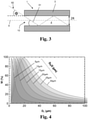
- the sketch of figure 3 serves to illustrate the coupling of the laser light beam 63 at the coupling point 10 into the hollow channel 4 filled with the test sample.
- the light beam 63 has an angle of incidence of less than 1 degree when it enters the hollow channel 4.
- the angle of incidence ⁇ (phi) results from the solution of the beam equation for the fundamental mode 31. It corresponds to the hollow channel-side acceptance angle for the fundamental mode 31 (which corresponds to half the opening angle) and at the same time the angle at which the fundamental mode is guided in the hollow channel 4 using a radiation-optical model approach.
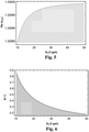
- the coupling efficiency for each hollow channel radius shows a pronounced maximum at a specific beam diameter.
- the maximum widens and at the same time shifts in the direction of larger jet diameters.
- an optimal jet diameter of around one third of the inner diameter of the hollow duct results.
- the optimum for the diameter ratio D L /D H is in the range of 0.3, with a limit value of at least 20% coupling efficiency being used.
- the angle results from the solution of the underlying equations that deliver n eff and can be converted into this angle.
- the angle in a ray-optical model can be interpreted as the angle at which a guided beam of the fundamental mode is reflected by a wall within the channel and at the same time as the exit angle of this beam from the capillary after it has passed through completely.
- the incident light should also be directed onto the capillary at this angle.
- the numerical aperture NA of the fundamental mode is plotted against the hollow channel radius D H /2 (in ⁇ m) for a hollow channel 4 filled with water. Accordingly, the optimal NA decreases with increasing hollow channel radius and reaches a value of 0.007 with a hollow channel radius of 30 ⁇ m. Analogously to the course of the reflection angle, it can be seen from the figure that the NA of the light to be coupled in must become increasingly smaller with increasing capillary diameter in order to couple efficiently into the fundamental mode.
- the particles 5 to be examined are taken up in an aqueous medium and placed on one end of the capillary as drops of liquid. Due to the sucking effect of the capillary force, the Liquid together with the particles it contains is drawn into the capillary interior and in doing so passes through the measuring range imaged by the microscope.
- the numerical aperture of the optical fiber 6 is designed in such a way that the laser beam 63 has an entry angle of less than 2 degrees.
- the measurement sample is guided in flow through the hollow channel 4, with the particles 5 in the aqueous medium diffusing freely within the hollow channel 4, in addition to a directed movement through the filling.
- a light beam 63 from an Nd:YAG laser 2 is coupled into the opening 10 of the hollow channel 4 via the optical fiber 6 and serves to illuminate the particles 5 in the hollow channel 4 .
- the illumination produces fluorescence and coherent and/or incoherent light scattering.
- a portion of the scattered light and fluorescent light leaves the hollow channel 4 through the capillary wall 3 and is captured by the sCMOS camera 8 .
- the detected scattered light is then processed and evaluated using software.
- the laser light not scattered by the particles 5 is reflected on the inner wall of the hollow channel and guided along the hollow channel 4 .
- this light guidance and because of the low surface roughness of the inner wall of the hollow channel 4 there is a low light attenuation along a signal detection length of up to about 20 cm and, as a result, an evaluable signal-to-background and signal-to-noise ratio, so that the detection of every illuminated particle 5 is allowed within the signal acquisition length.
- the hollow channel 4 also offers the possibility of one- or two-dimensional enclosure of the sample volume, whereby the sample particles 5 to be examined can be kept in the measurement area over long measurement times.
Description
Die Erfindung betrifft eine Vorrichtung nach Anspruch 1 zur Analyse von Partikeln, umfassend
- eine Glas-Kapillare als Messzelle mit einem Hohlkanal zur Aufnahme oder zur Durchleitung einer die Partikel enthaltenden Messprobe, der eine Hohlkanal-Längsachse und eine Hohlkanal-Innenwandung aufweist,
- eine Lichtquelle zur Erzeugung eines Lichtstrahls und eine optische Einrichtung zur Einkopplung des Lichtstrahls an einer Einkoppelstelle in den Hohlkanal zwecks Beleuchtung der Messprobe, wobei der Lichtstrahl bei Eintritt in den Hohlkanal einen Einstrahlwinkel Φ bezüglich der Hohlkanal-Längsachse von weniger als 2 Grad hat, und
- einen Detektor zur Erfassung von aus dem Hohlkanal austretendem Streulicht.
- a glass capillary as a measuring cell with a hollow channel for receiving or for passing through a measurement sample containing the particles, which has a hollow channel longitudinal axis and a hollow channel inner wall,
- a light source for generating a light beam and an optical device for coupling the light beam at a coupling point into the hollow channel for the purpose of illuminating the measurement sample, the light beam entering the hollow channel at an angle of incidence Φ with respect to the longitudinal axis of the hollow channel of less than 2 degrees, and
- a detector for detecting scattered light emerging from the hollow channel.
Außerdem betrifft die Erfindung ein Verfahren nach Anspruch 11 zur Analyse von Partikeln, umfassend die folgenden Verfahrensschritte:
- Breitstellen einer Messzelle in Form einer Glas-Kapillare mit einem eine Hohlkanal-Längsachse und eine Hohlkanal-Innenwandung aufweisenden Hohlkanal,
- Einbringen einer die Partikel enthaltenden Messprobe in den Hohlkanal, wobei die Messprobe einen Brechungsindex ΔnM aufweist
- Erzeugen eines Lichtstrahls mittels einer Lichtquelle,
- Einkoppeln des Lichtstrahls an einer Einkoppelstelle in den Hohlkanal zwecks Beleuchtung der Messprobe mittels einer optischen Einkoppel-Einrichtung, wobei der Lichtstrahl bei Eintritt in den Hohlkanal einen Einstrahlwinkel Φ bezüglich der Hohlkanal-Längsachse von weniger als 2 Grad hat, und
- Erfassen von aus dem Hohlkanal austretendem Streulicht mittels eines Detektors.
- Providing a measuring cell in the form of a glass capillary with a hollow channel having a longitudinal axis and a hollow channel inner wall,
- Introduction of a measurement sample containing the particles into the hollow channel, the measurement sample having a refractive index Δn M
- generating a light beam by means of a light source,
- Coupling the light beam at a coupling point into the hollow channel for the purpose of illuminating the measurement sample by means of an optical coupling device, the light beam entering the hollow channel at an angle of incidence Φ with respect to the longitudinal axis of the hollow channel of less than 2 degrees, and
- Detection of scattered light emerging from the hollow channel by means of a detector.
Methoden zur Charakterisierung einer Probe in einem fluiden Medium sind in der medizinischen und biologischen Grundlagenforschung sowie als Routinediagnostikmethode in zahlreichen Medizinalbereichen in Kliniken üblich.Methods for characterizing a sample in a fluid medium are common in medical and biological basic research and as a routine diagnostic method in numerous medical areas in clinics.
Eine gebräuchliche Methode ist die Durchflusszytometrie, bei der das an Teilchen gestreute Licht analysiert wird. Sie erfordert wenig apparativen Aufwand und ist grundsätzlich für eine kostengünstige Analytik einsetzbar. Eine dafür geeignete Streulicht-Messanordnung ist aus der
Dabei ergibt sich jedoch häufig wegen eines hohen Hintergrundsignals mit einem schlechten Signal-zu-Rausch-Verhältnis eine geringe Messempfindlichkeit. Daher ist es oftmals notwendig Fluoreszenzlicht anstelle von Streulicht zu betrachten, um ein stärkeres Signal zu erlangen, welches vom Untergrund abgelöst werden kann. Die wenigsten Probenteilchen jedoch zeigen natürliche Fluoreszenz, weshalb in diesen Fällen eine Präparation der Proben mit Erweiterung um eine fluoreszierende Gruppe notwendig ist.However, this often results in low measurement sensitivity due to a high background signal with a poor signal-to-noise ratio. Therefore, it is often necessary to look at fluorescence light instead of scattered light in order to get a stronger signal that can be separated from the background. However, very few sample particles show natural fluorescence, which is why it is necessary in these cases to prepare the samples with an addition of a fluorescent group.
Eine höhere Messempfindlichkeit ergibt sich bei einer Analysevorrichtung und einem Analyseverfahren gemäß der eingangs genannten Gattung, wie in der
Das durch die Hohlkanal-Wandung austretende Streulicht wird von einem Detektor erfasst. Dieser ist beispielsweise zum Messen der kohärenten Streuintensität des Streulichts, der inkohärenten Streuintensität des Streulichts, der spektralen Verteilung des Streulichts, der räumlichen Verteilung des Streulichts und / oder der dynamischen Bewegung der zu messenden Partikel ausgelegt. Ergänzend dazu kann der Detektor auch zum Erfassen von Fluoreszenz-Streulicht ausgelegt sein, das durch die Beleuchtung der zu messenden Partikel erzeugt wird.The scattered light exiting through the wall of the hollow channel is detected by a detector. This is designed, for example, to measure the coherent scattered intensity of the scattered light, the incoherent scattered intensity of the scattered light, the spectral distribution of the scattered light, the spatial distribution of the scattered light and/or the dynamic movement of the particles to be measured. In addition to this, the detector can also be designed to detect scattered fluorescence light that is generated by the illumination of the particles to be measured.
Der auf einen Öffnungsquerschnitt von weniger als 0,2 µm2 begrenzte Hohlkanal wird mit Flüssigkeit gefüllt, die die zu untersuchenden Partikel enthält. Die Natur der Wechselwirkung zwischen Licht und Materie bewirkt, dass das Beleuchtungslicht wenig im Quarzglas aber deutlich stärker an den in der Flüssigkeit befindlichen Partikeln streut. Das gestreute Mess-Licht wird mittels einer Kamera aufgefangen und zur Analyse prozessiert. Eine kleine Kern-Querschnittsfläche und ein großer Brechzahlunterschied zwischen Kern und Mantel begünstigen den räumlichen Einschluss des Beleuchtungslichts im Kernbereich des Lichtwellenleiters und verbessern die Ausleuchtung des Hohlkanals. Es wird erwähnt, dass der Hohlkanal als Kapillare ausgebildet sein kann. Eine ähnliche Analysevorrichtung und ein Analyseverfahren beschreibt die
Aus der
Aus der
Die Messgeschwindigkeit bei derartigen Analysemethoden wird durch den Öffnungsquerschnitt des Hohlkanals limitiert. Dieser ist gemäß der
Von daher wäre der Einsatz einer Kapillare als Hohlkanal bei der Analyse von Partikeln, wie beispielsweise bei der Durchflusszytometrie, grundsätzlich wünschenswert, wirft jedoch eine Vielzahl anderer technischer Probleme, wie etwa die Realisierung eines ausreichend hohen Signal-Rausch-Verhältnisses, auf, die im Stand der Technik weder angesprochen noch gelöst sind.Therefore, the use of a capillary as a hollow channel in the analysis of particles, such as in flow cytometry, would be desirable in principle, but raises a number of other technical problems, such as the realization of a sufficiently high signal-to-noise ratio, on that are neither addressed nor solved in the prior art.
Der Erfindung liegt daher die Aufgabe zugrunde, eine Vorrichtung zur Analyse von Partikeln zur Verfügung zu stellen, bei der eine Kapillare als Messzelle einsatzbar ist, und die eine verlässliche, reproduzierbare Messung mit hohem Signal-Rausch-Verhältnis ermöglicht.The invention is therefore based on the object of providing a device for analyzing particles, in which a capillary can be used as a measuring cell and which enables a reliable, reproducible measurement with a high signal-to-noise ratio.
Außerdem liegt der Erfindung die Aufgabe zugrunde, ein Verfahren zur Analyse von Partikeln anzugeben, das eine verlässliche, reproduzierbare Messung mit hohem Signal-Rausch-Verhältnis erlaubt.In addition, the invention is based on the object of specifying a method for analyzing particles that allows a reliable, reproducible measurement with a high signal-to-noise ratio.
Hinsichtlich der Vorrichtung wird diese Aufgabe ausgehend von einer Vorrichtung der eingangs genannten Gattung erfindungsgemäß dadurch gelöst, dass
- dass der Hohlkanal einen Innendurchmesser DH im Bereich von 10 µm bis 60 µm aufweist, und
- dass der Lichtstrahl eine radiale Lichtintensitätsverteilung mit einem minimalen Strahldurchmesser DL hat, wobei für das Durchmesserverhältnis DL/DH gilt: 0,05<DL/DH<2,00.
- that the hollow channel has an internal diameter D H in the range from 10 μm to 60 μm, and
- that the light beam has a radial light intensity distribution with a minimum beam diameter D L , where the following applies to the diameter ratio D L /D H : 0.05<D L /D H <2.00.
Bei der erfindungsgemäßen Analyse-Vorrichtung ist die Messzelle als Glas-Kapillare ausgeführt, deren Innenbohrung den Hohlkanal zur Aufnahme oder zur Durchleitung der zu analysierenden Messprobe bildet. Die Messprobe ist dabei im Hohlkanal eingeschlossen oder sie wird im Durchfluss durch den Hohlkanal geleitet.In the analysis device according to the invention, the measuring cell is designed as a glass capillary, the inner bore of which forms the hollow channel for receiving or for passing through the measurement sample to be analyzed. The measurement sample is enclosed in the hollow channel or it is passed through the hollow channel as it flows through.
Die Glas-Kapillare ist im einfachsten Fall als Hohlzylinder aus optisch einheitlichem Glasmaterial ausgeführt, so dass die Kapillar-Wandung einen radial homogenen Brechzahlverlauf aufweist. Der Hohlkanal bei der erfindungsgemäßen Messzelle verfügt daher im Unterschied zu der bekannten Messzelle nicht über eine auf Totalreflexion beruhenden und zur Ausleuchtung des Hohlkanals beitragenden Lichtführung in Form einer optischen Wellenleiterstruktur. Eine derartige Wellenleiterstruktur einer Hohlzylinder-Wandung könnte eine Lichtführung ermöglichen, die theoretisch lateral zur Hohlzylinderachse dissipationsfrei wäre und damit eine homogene Ausleuchtung in der durch die Hohlzylinder-Innenwand gebildeten Innenbohrung über eine lange Strecke ermöglichen würde. Eine Kapillare einheitlichen Brechzahlverlaufes (wie hier) führt jedoch im Allgemeinen kein Licht im Innenvolumen des durch die Kapillar-Wandung gebildeten Hohlkanals. Um dennoch eine Messung mit hohem Signal-Rausch-Verhältnis und hoher Mess-Empfindlichkeit zu erreichen, sind eine effiziente Einkopplung des Lichtstrahls in den Hohlkanal und für die Anwendung hinreichend geringe Übertragungsverluste anzustreben.In the simplest case, the glass capillary is designed as a hollow cylinder made of optically uniform glass material, so that the capillary wall has a radially homogeneous refractive index profile. In contrast to the known measuring cell, the hollow channel in the measuring cell according to the invention therefore does not have a light guide in the form of an optical waveguide structure that is based on total reflection and contributes to the illumination of the hollow channel. Such a waveguide structure of a hollow cylinder wall could enable light guidance, which would theoretically be dissipation-free laterally to the axis of the hollow cylinder and would thus enable homogeneous illumination over a long distance in the inner bore formed by the inner wall of the hollow cylinder. However, a capillary with a uniform refractive index profile (as here) generally does not guide any light in the inner volume of the hollow channel formed by the capillary wall. In order to nevertheless achieve a measurement with a high signal-to-noise ratio and high measurement sensitivity, efficient coupling of the light beam into the hollow channel and sufficiently low transmission losses for the application are desirable.
Daher ist bei der hier präsentierten Vorrichtung vorgesehen, durch Auswahl und Einstellung konstruktiver Maßnahmen zur Strahlführung Licht derart in den Hohlkanal einzubringen, dass sich definierte Intensitätsprofile in der Normalebene zur Hohlkanal-Längsachse ausbilden, sogenannte Moden, die entlang der Hohlkanal-Längsachse geführt werden, jedoch physikalisch intrinsisch einem Energieverlust durch eine laterale Dissipation von Energie unterliegen. Um diesen Energieverlust zu minimieren, ist zu gewährleisten, dass die Einkopplung des Lichtes in den Kapillar-Hohlkanal derart durchgeführt wird, dass ein großer Anteil der Leistung, insbesondere der größte Anteil der Leistung, in der sogenannten Grundmode geführt wird. Die Intensitätsverteilung der Grundmose trägt zum einen zu einer im Vergleich zu allen anderen möglichen Moden besonders homogenen Ausleuchtung des Hohlkanal-Volumens bei, so dass eine besonders störungsfreie Messung der zu analysierenden Partikel ermöglicht wird. Zum anderen wird hierdurch gewährleistet, dass das Licht entlang der Kapillar-Längsachse und insbesondere entlang einer vorgegebenen Messstrecke mit möglichst geringem Verlust geführt wird. Ursache hierfür ist, dass die Verluste durch Energiedissipation quer zur Hohlkanal-Längsachse für die Grundmode niedriger sind als für alle anderen Moden.Therefore, the device presented here is intended to introduce light into the hollow duct by selecting and adjusting constructive measures for beam guidance in such a way that defined intensity profiles are formed in the normal plane to the longitudinal axis of the hollow duct, so-called modes, which are guided along the longitudinal axis of the hollow duct, however physically intrinsically subject to energy loss through lateral dissipation of energy. In order to minimize this energy loss, it must be ensured that the light is coupled into the capillary hollow channel in such a way that a large proportion of the power, in particular the largest proportion of the power, is guided in the so-called basic mode. On the one hand, the intensity distribution of the ground moss contributes to a particularly homogeneous illumination of the hollow channel volume compared to all other possible modes, so that a particularly interference-free measurement of the particles to be analyzed is made possible. On the other hand, this ensures that the light is guided along the longitudinal axis of the capillary and in particular along a predetermined measurement path with as little loss as possible. The reason for this is that the losses due to energy dissipation transverse to the longitudinal axis of the hollow channel are lower for the fundamental mode than for all other modes.
Ferner vermindert die vorzugsweise Einstrahlung der Lichtleistung in die Grundmode den unerwünschten Effekt des sogenannten "Modenmischens". Dabei kommt es entlang eines Lichtleiters zu einem Verteilen der Lichtenergie von einer Mode auf eine andere Mode. Dies führt zu einem entlang der Lichtleiter-Längsachse variierendem Intensitätsprofil innerhalb dessen Normalebene, wobei die genaue Bestimmung des Intensitätsprofiles durch eine Fülle von Faktoren erschwert wird. Die Kenntnis dieses Intensitätsprofiles ist jedoch für die Qualifizierung der zu analysierenden Partikel hilfreich.Furthermore, the preferential irradiation of the light power into the fundamental mode reduces the undesired effect of the so-called "mode mixing". In this case, the light energy is distributed along a light guide from one mode to another mode. This leads to an intensity profile that varies along the longitudinal axis of the light guide within its normal plane, with the exact determination of the intensity profile being made more difficult by a multitude of factors will. However, knowledge of this intensity profile is helpful for qualifying the particles to be analyzed.
Die oben erwähnten konstruktiven Maßnahmen werden im Folgenden näher erläutert:
- (1) Die vergleichsweise schwache Lichtführung im Hohlkanal der Kapillare führt zu einer hohen Lichtdämpfung des eingekoppelten Lichtstrahls. Es hat sich gezeigt, dass die Dämpfung vom Kapillar-Innendurchmesser abhängt und umso höher ist, je kleiner der Innendurchmesser ist.
- (1) The comparatively weak light guidance in the hollow channel of the capillary leads to a high light attenuation of the coupled light beam. It has been shown that the damping depends on the inner diameter of the capillary and is higher the smaller the inner diameter.
Der Hohlkanal weist daher einen Innendurchmesser DH im Bereich von 10 µm bis 60 µm auf. Bei einem Hohlkanal-Innendurchmesser von weniger als 10 µm ergibt sich eine hohe Lichtdämpfung, die die Durchführung einer verlässlichen, reproduzierbaren Messung mit hohem Signal-Rausch-Verhältnis erschwert. Vorzugsweise beträgt der Hohlkanal-Innendurchmesser daher mindestens 20 µm. Der Hohlkanal enthält die zu analysierenden Probenteilchen, die sich in dem zur Verfügung stehenden Hohlkanal-Volumen frei bewegen können. Die Beweglichkeit in lateraler Richtung (senkrecht zur Hohlkanal-Längsachse) ist durch den Hohlkanal-Innendurchmesser begrenzt. Bei einem Hohlkanal-Innendurchmesser von mehr als 60 µm sind das Volumen und insbesondere die Teilchen-Beweglichkeit in lateraler Richtung so groß, dass eine zuverlässige Erfassung durch den Detektor wegen limitierter Tiefenschärfe erschwert wird.The hollow channel therefore has an inside diameter D H in the range from 10 μm to 60 μm. With a hollow channel internal diameter of less than 10 µm, there is high light attenuation, which makes it difficult to carry out a reliable, reproducible measurement with a high signal-to-noise ratio. The inner diameter of the hollow channel is therefore preferably at least 20 μm. The hollow channel contains the sample particles to be analyzed, which can move freely in the available hollow channel volume. The mobility in the lateral direction (perpendicular to the longitudinal axis of the hollow channel) is limited by the inner diameter of the hollow channel. With a hollow channel internal diameter of more than 60 µm, the volume and in particular the particle mobility in the lateral direction are so large that reliable detection by the detector is made more difficult due to the limited depth of focus.
Der von der Lichtquelle erzeugte Lichtstrahl tritt an einer stirnseitigen Einkoppelstelle in den Hohlkanal ein (=stirnseitige Öffnung des Hohlkanals), und beim weiteren Propagieren durch den Hohlkanal wird er an den darin enthaltenen Probenteilchen unter Abgabe von Streulicht gestreut und dabei gedämpft. Das Streulicht wird mittels des Detektors erfasst. Die Streulicht-Erfassung kann direkt an der Einkoppelstelle einsetzen, wobei dort aber zusätzliche Reflexionen und parasitäre Streueffekte auftreten, was eine exakte Erfassung der Teilchenstreuung und deren Auswertung erschwert. Daher ist der Beginn der Streulicht-Erfassung bevorzugt in Einstrahlrichtung gesehen der Einkoppelstelle nachgeordnet, beispielsweise über eine Länge von mindestens 2 mm.The light beam generated by the light source enters the hollow channel at a front coupling point (= front opening of the hollow channel), and as it propagates further through the hollow channel, it is scattered by the sample particles contained therein, emitting scattered light and is attenuated in the process. The scattered light is recorded by the detector. Scattered light detection can start directly at the coupling point, but additional reflections and parasitic scattering effects occur there, which makes exact detection of the particle scattering and its evaluation more difficult. Therefore, the start of the detection of scattered light is preferably downstream of the coupling point, as viewed in the direction of incidence, for example over a length of at least 2 mm.
Als "Streulicht" wird hier dasjenige Beleuchtungs-Licht verstanden, das den Hohlkanal durch die Kapillar-Wandung verlässt und das vom Detektor erfasst wird. Die Wandung ist transparent für das Beleuchtungslicht."Scattered light" is understood here to mean that illuminating light which leaves the hollow channel through the capillary wall and which is detected by the detector. The wall is transparent to the illumination light.
(2) Für die Übertragung des Lichtstrahls von der Lichtquelle zur Einkoppelstelle ist eine optische Übertragungseinrichtung vorgesehen. Diese umfasst beispielsweise eine optische Faser oder eine Anordnung optischer Bauteile zur Übertragung eines Freistrahls. Die Einkopplung des Lichtstrahls in den Hohlkanal wird maßgeblich von der numerischen Apertur (im Folgenden als "NA" bezeichnet) der optischen Übertragungseinrichtung und vom Durchmesserverhältnis von minimale Strahldurchmesser und Hohlkanal-Innendurchmesser bestimmt. Bei der erfindungsgemäßen Vorrichtung wird eine optische Übertragungseinrichtung mit vergleichsweise kleiner NA eingesetzt. Dies zeigt sich darin, dass der Lichtstrahl eine radiale Lichtintensitätsverteilung mit einem minimalen Strahldurchmesser DL aufweist, der in etwa so groß ist, wie der Innendurchmesser DH des Hohlkanals, genauer gesagt gilt für das Durchmesserverhältnis DL/DH der Zusammenhang:0,05<DL/DH<2,00, vorzugsweise: 0,1<DL/DH<1,00 und besonders bevorzugt: 0,2<DL/DH<0,5.(2) An optical transmission device is provided for the transmission of the light beam from the light source to the coupling point. This includes, for example, an optical fiber or an arrangement of optical components for transmitting a free beam. The coupling of the light beam into the hollow channel is largely determined by the numerical aperture (hereinafter referred to as “NA”) of the optical transmission device and by the diameter ratio of the minimum beam diameter and the inside diameter of the hollow channel. In the device according to the invention, an optical transmission device with a comparatively small NA is used. This is shown by the fact that the light beam has a radial light intensity distribution with a minimum beam diameter DL , which is approximately as large as the inner diameter DH of the hollow channel, more precisely, the relationship for the diameter ratio DL /D H applies : 0, 05<D L /D H <2.00, preferably: 0.1<D L /D H <1.00 and particularly preferably: 0.2<D L /D H <0.5.
Der minimale Strahldurchmesser DL wird im Fall eines Freistrahls von der Taillenbreite im Strahlfokus bestimmt und bei einer Faserzuführung vom Kerndurchmesser am Lichtaustrittsende der Lichtleitfaser.In the case of a free beam, the minimum beam diameter D L is determined by the waist width in the beam focus and, in the case of a fiber feed, by the core diameter at the light exit end of the optical fiber.
Der Abstand zwischen der Ebene mit minimalem Strahldurchmesser DL und der stirnseitigen Öffnung des Hohlkanals ist möglichst klein; er beträgt bevorzugt weniger als 10 mm und liegt im Idealfall bei Null.The distance between the plane with the minimum beam diameter D L and the end opening of the hollow channel is as small as possible; it is preferably less than 10 mm and ideally is zero.
(3) Die oben unter (2) erläuterte Maßnahme ist grundsätzlich durch eine hinreichend starke Fokussierung des Lichtstrahls erreichbar. Eine starke Fokussierung geht jedoch mit einer hohen Divergenz des Lichtstrahls einher. Es hat sich aber gezeigt, dass ein kleiner Divergenzwinkel erforderlich und dementsprechend eine geringe Fokussierung des Lichtstrahls anzustreben ist. Denn trifft der Lichtstrahl in einem flachen Winkel auf die stirnseitige Öffnung des Hohlkanals, so wird in Abhängigkeit vom Einstrahlwinkel ein Teil des Lichtes an der Hohlkanal-Innenwandung reflektiert und ein anderer Teil wird in die Kapillarwand eindringen und die Kapillare energieverlustreich als Verlustlicht verlassen. Zu Gunsten eines hohen Anteils an reflektiertem Licht und möglichst wenig Verlustlicht und damit einhergehend einer möglichst großen Erfassungslänge, hat der Lichtstrahl bei Eintritt in den Hohlkanal einen Einstrahlwinkel von weniger als 2 Grad, und vorzugsweise weniger als 1 Grad. Als Einstrahlwinkel wird hierbei der hohlkanalseitige Akzeptanzwinkel definiert (entspricht dem halben Öffnungswinkel).(3) The measure explained above under (2) can basically be achieved by sufficiently focusing the light beam. However, strong focusing is accompanied by a high divergence of the light beam. However, it has been shown that a small angle of divergence is necessary and that a correspondingly small focus of the light beam is to be aimed for. Because the light beam hits the front opening of the hollow duct at a flat angle, depending on the angle of incidence, part of the light is reflected on the inner wall of the hollow duct and another part penetrates the capillary wall and leaves the capillary as lost light with a high energy loss. In favor of a high proportion of reflected light and as little lost light as possible and, associated with this, the greatest possible detection length, the light beam has an angle of incidence of less than 2 degrees and preferably less than 1 degree when it enters the hollow channel. The angle of acceptance on the hollow channel side is defined as the angle of incidence (corresponds to half the opening angle).
Die Anforderungen hinsichtlich eines vergleichsweise geringen Strahldurchmessers einerseits und eines geringen Divergenzwinkels andererseits stehen in einem gewissen Widerspruch zueinander. Die Kombination dieser Maßnahmen bei der erfindungsgemäßen Vorrichtung bewirkt jedoch die weiter oben erläuterte Strahlführung, bei der ein hoher Anteil der eingekoppelten Lichtleitung in die Grundmode überführt wird.The requirements with regard to a comparatively small beam diameter on the one hand and a small angle of divergence on the other are somewhat contradictory. However, the combination of these measures in the device according to the invention brings about the beam guidance explained above, in which a high proportion of the coupled-in light guide is converted into the fundamental mode.
In dem Zusammenhang wird eine Ausführungsform der Vorrichtung bevorzugt, bei der die Glas-Kapillare aus Quarzglas besteht.In this context, an embodiment of the device is preferred in which the glass capillary consists of quartz glass.
Quarzglas ist über einen breiten Wellenlängenbereich zwischen etwa 150 nm und 3000 nm weitgehend transparent. Somit ermöglicht die Glas-Kapillare eine Beleuchtungsstrahlung mit Wellenlängen im Bereich von UV bis Infrarot, und zwar bei kleinem Streubeitrag durch die Kapillar-Wandung. Darüber hinaus erleichtert der Werkstoff Quarzglas auch bei Hohlkanälen mit kleinem Öffnungsquerschnitt die Realisierung besonders glatter Innenwandungen durch ein verhältnismäßig großes Temperaturintervall, in welchem die Kapillare durch Heißumformung gezogen werden kann. Das Quarzglas der Kapillare kann undotiert sein. Es kann auch einen oder mehrere Dotierstoffe enthalten.Quartz glass is largely transparent over a wide range of wavelengths between about 150 nm and 3000 nm. The glass capillary thus enables illumination radiation with wavelengths in the range from UV to infrared, with a small contribution to scattering through the capillary wall. In addition, the quartz glass material makes it easier to achieve particularly smooth inner walls, even in the case of hollow channels with a small opening cross section, thanks to a relatively large temperature interval in which the capillary can be drawn by hot forming. The quartz glass of the capillary can be undoped. It can also contain one or more dopants.
Der Brechungsindex des Glases ΔnK der Kapillare ist vorzugsweise abgestimmt auf den Brechungsindex ΔnM der gemäß Spezifikation oder einer anderen Einsatzvorgabe aufzunehmenden Messprobe. ΔnK ist vorzugsweise größer, und besonders bevorzugt um mindestens 0,1 größer als ΔnM (jeweils gemessen bei der Messwellenlänge: 532 nm und der Messtemperatur: 20 °C). Die Messprobe ist in der Regel in einem wässrigen Medium aufgenommen. Für den Brechungsindex von Wasser gegen Luft werden in der Literatur Werte um 1,33 (Messparameter wie oben genannt) angegeben. Der Brechungsindex von Quarzglas liegt bei etwa 1,45, so dass eine Kapillare aus Quarzglas die obige bevorzugte Bemessungsregel ΔnM < ΔnK - 0,1 grundsätzlich erfüllt.The refractive index of the glass Δn K of the capillary is preferably matched to the refractive index Δn M of the measurement sample to be taken according to the specification or another application requirement. Δn K is preferably greater, and particularly preferably at least 0.1 greater than Δn M (measured in each case at the measurement wavelength: 532 nm and the measurement temperature: 20° C.). The measurement sample is usually taken up in an aqueous medium. Values of around 1.33 (measurement parameters as mentioned above) are given in the literature for the refractive index of water against air. The refractive index of quartz glass is about 1.45, so that a capillary made of quartz glass basically satisfies the above preferred dimensioning rule Δn M < Δn K - 0.1.
Im Hinblick auf geringe Übertragungsverluste im Hohlkanal hat es sich bewährt, wenn die Glas-Kapillare möglichst nicht gebogen ist, sondern im Gegenteil, über ihre Gesamtlänge, insbesondere mindestens über die Signal-Erfassungslänge, gerade ist. Als "gerade" wird hier ein Verlauf verstanden, bei dem die Positionen der Kapillar-Längsachse am Anfang und am Ende der Signal-Erfassungslänge in einer Projektion senkrecht zur Einstrahlrichtung einen Abstand von weniger als 1 mm voneinander haben. Die Signal-Erfassungslänge entspricht demjenigen Längenabschnitt der Kapillare, entlang dem eine Streulicht-Erfassung vorgesehen ist, dieser Längenabschnitt beträgt mindestens 2 mm und maximal 20 cm - gemessen von der Einkoppelstelle.With regard to low transmission losses in the hollow channel, it has proven useful if the glass capillary is not bent if possible, but on the contrary is straight over its entire length, in particular at least over the signal detection length. Here, “straight” is understood to mean a profile in which the positions of the capillary longitudinal axis at the beginning and at the end of the signal detection length are less than 1 mm apart in a projection perpendicular to the irradiation direction. The signal detection length corresponds to that length section of the capillary along which scattered light detection is provided; this length section is at least 2 mm and at most 20 cm—measured from the coupling point.
Der unerwünschte Effekt der "Modenmischung" wird auch durch Biegungen der Kapillare und lokal wirkende mechanische Zug- oder Druckspannungen verstärkt. Durch Einstellung einer hohen Biegesteifheit beziehungsweise eines ausreichend hohen Flächenträgheitsmoments, insbesondere hervorgerufen durch eine große Dicke der Kapillar-Wandung, können mechanische Spannungen aufgenommen und Biegungen unterdrückt werden.The undesired effect of "mode mixing" is also increased by bending of the capillary and locally acting mechanical tensile or compressive stresses. By setting a high bending stiffness or a sufficiently high moment of inertia, caused in particular by a large thickness of the capillary wall, mechanical stresses can be absorbed and bending can be suppressed.
Andererseits kann die Hohlkanal-Wandung Streuzentren enthalten und sie trägt zur optischen Dämpfung des vom Detektor zu erfassenden Streulichts bei.On the other hand, the wall of the hollow channel can contain scattering centers and it contributes to the optical attenuation of the scattered light to be detected by the detector.
Es hat sich daher bewährt, wenn die Glas-Kapillare eine Hohlkanal-Wandung mit einer Wandstärke von mindestens 100 µm, mindestens 500 µm und vorzugsweise mindestens 1000 µm sowie eine Wandstärke von maximal 10 mm, maximal 5 mm und vorzugsweise maximal 2 mm aufweist, wobei die Hohlkanal-Wandung in radialer Richtung gesehen einen homogenen Brechzahlverlauf aufweist.It has therefore proven useful if the glass capillary has a hollow channel wall with a wall thickness of at least 100 μm, at least 500 μm and preferably at least 1000 μm and a wall thickness of at most 10 mm, at most 5 mm and preferably at most 2 mm, with the hollow channel wall has a homogeneous refractive index curve when viewed in the radial direction.
Bei einer besonders bevorzugten Ausführungsform ist die optische Einrichtung als Multimode- oder als Singlemode-Lichtleitfaser mit einem Faserkern und einem den Faserkern umhüllenden Mantel ausgebildet ist, und wobei die optische Faser eine numerische Apertur NA aufweist, für die gilt: NA < 0,05.In a particularly preferred embodiment, the optical device is in the form of a multimode or single-mode optical fiber with a fiber core and a cladding encasing the fiber core, and the optical fiber has a numerical aperture NA for which the following applies: NA<0.05.
Die atypisch geringe NA der Lichtleitfaser erleichtert die Realisierung eines möglichst flachen Einstrahlwinkels und trägt insoweit zur Verbesserung der Einkoppeleffizienz und Führung des Lichtstrahls im Kapillar-Hohlkanal bei.The atypically low NA of the optical fiber facilitates the realization of an incidence angle that is as flat as possible and in this respect contributes to improving the coupling efficiency and guidance of the light beam in the capillary hollow channel.
Die in einer multimodalen Lichtleitfaser geführten Lichtmoden haben in der Messprobe unterschiedliche Brechungsindizes und werden unterschiedlich gedämpft. Für die einzige Mode der unimodalen Lichtleitfaser können die Parameter für die Einkopplung optimiert werden, so dass sich eine vergleichsweise höhere Einkoppeleffizienz, insbesondere in die Grundmode der Kapillare, ergibt.The light modes guided in a multimode optical fiber have different refractive indices in the measurement sample and are attenuated differently. The parameters for the in-coupling can be optimized for the only mode of the unimodal optical fiber, resulting in a comparatively higher in-coupling efficiency, in particular in the fundamental mode of the capillary.
Unabhängig davon erweist es sich insbesondere im Hinblick auf eine hohe Einkoppeleffizienz als nützlich, wenn die optische Faser einen Modenfelddurchmesser DM aufweist. , der im Verhältnis zum Innendurchmesser DH des Hohlkanals in folgendem Zusammenhang steht: 0,05<DM/DH<2,00, vorzugsweise:
0,1<DM/DH<1,00 und besonders bevorzugt: 0,2<DM/DH<0,5.Irrespective of this, it proves to be useful, particularly with regard to high coupling efficiency, if the optical fiber has a mode field diameter D M . , which is related to the inside diameter D H of the hollow channel as follows: 0.05<D M /D H <2.00, preferably:
0.1<D M /D H <1.00 and particularly preferably: 0.2<D M /D H <0.5.
Der Modenfelddurchmesser ist ein Parameter zur Kennzeichnung der Lichtverteilung der Grundmode in der Singlemodefaser. Bei einer durch eine Gaußkurve approximierbaren radialen Lichtintensitätsverteilung ist der Modenfelddurchmesser derjenige, bei dem die Amplitude der Lichtintensität auf 1/e abgefallen ist (etwa 37 %).The mode field diameter is a parameter characterizing the light distribution of the fundamental mode in the singlemode fiber. With a radial light intensity distribution that can be approximated by a Gaussian curve, the mode field diameter is that at which the amplitude of the light intensity has fallen to 1/e (about 37%).
Der Detektor ist vorzugsweise so ausgelegt, dass er das Streulicht entlang einer Signal-Erfassungslänge erfasst, deren Länge mindestens 2 mm und maximal 20 cm ab der Einkoppelstelle beträgt.The detector is preferably designed in such a way that it detects the scattered light along a signal detection length, the length of which is at least 2 mm and at most 20 cm from the coupling point.
Bei Erfassungslängen von mehr als 20 cm wird eine homogene Ausleuchtung des Probenvolumens durch die Dämpfung des Lichtstrahls entlang der Erfassungslänge erschwert.With detection lengths of more than 20 cm, homogeneous illumination of the sample volume is made more difficult by the attenuation of the light beam along the detection length.
Im Hinblick auf eine höhere Messgenauigkeit erweist es sich als günstig, wenn der Hohlkanal einen Innenquerschnitt mit mindestens einer Abflachung aufweist und/oder dass die Kapillare einen Außenquerschnitt mit mindestens einer Abflachung aufweist hat.With regard to a higher measurement accuracy, it proves to be advantageous if the hollow channel has an inner cross section with at least one flattened area and/or that the capillary has an outer cross section with at least one flattened area.
Bei einem runden Innenquerschnitt und einem runden Außenquerschnitt ist das Messfenster, durch das der Detektor das Streulicht erfasst gekrümmt. Die Krümmung führt zu Verzerrungen der Abbildung und unerwünschten Ablenkungen des Streulichts beziehungsweise zu optischen Fehlern in der Abbildung und muss bei der Auswertung berücksichtigt werden. Die Auswertung wird vereinfacht, wenn mindestens die innere oder mindestens die äußere Messfenster-Begrenzungsfläche eben ist, und ist besonders, wenn beide Messfenster-Begrenzungsflächen eben sind. Dies wird durch eine einseitige oder beidseitige Abflachung der Kapillar-Wandung erreicht. Die einseitige oder beidseitige Abflachung ist auch durch einen polygonalen Innen- und/oder Außenquerschnitt erreichbar.With a round inner cross-section and a round outer cross-section, the measuring window through which the detector captures the scattered light is curved. The curvature leads to image distortions and undesirable deflections of the image Stray light or optical errors in the image and must be taken into account in the evaluation. The evaluation is simplified when at least the inner or at least the outer boundary surface of the measurement window is flat, and is particularly so when both boundary surfaces of the measurement window are flat. This is achieved by flattening the capillary wall on one or both sides. One-sided or two-sided flattening can also be achieved by a polygonal inner and/or outer cross section.
Bei einer besonders bevorzugten Ausführungsform der Vorrichtung ist der Hohlkanal in einem plattenförmigen Körper mit sich gegenüberliegenden Flachseiten ausgebildet, wobei die Flachseiten des Körpers Außenwandungen der Kapillare bilden.In a particularly preferred embodiment of the device, the hollow channel is formed in a plate-shaped body with flat sides lying opposite one another, the flat sides of the body forming the outer walls of the capillary.
Der plattenförmige Körper hat beispielsweise Rechteckform, insbesondere die Form eines Mikroskop-Objektträgers, und er zeichnet sich vorzugsweise durch hohe Biegesteifigkeit aus. Der plattenförmige Körper bildet die Kapillare oder die Kapillare ist in dem plattenförmigen Körper integriert. Sie kann innerhalb der Rechteckform beispielsweise in Längsrichtung verlaufen.The plate-shaped body has, for example, a rectangular shape, in particular the shape of a microscope slide, and it is preferably characterized by high flexural rigidity. The plate-shaped body forms the capillary or the capillary is integrated in the plate-shaped body. It can run in the longitudinal direction within the rectangular shape, for example.
Kapillaren werden in der Regel durch Elongieren eines Hohlzylinders erzeugt. Dabei können sich sowohl an der Hohlkanal-Innenwandung als auch an der Kapillar-Außenwandung Ziehstreifen und andere Oberflächenstrukturen ausbilden, die Störungen im Messweg der Streulichtmessung darstellen und durch Reflexion und Streuung das Messergebnis beeinträchtigen. Um Verfälschungen durch parasitäre Streueffekte und Grenzflächen möglichst zu vermeiden, wird eine möglichst glatte Hohlkanal-Innenwandung angestrebt, eine Oberflächenrauigkeit aufweist, die definiert ist durch eine mittlere Rautiefe Ra von weniger als 1 nm.Capillaries are usually created by elongating a hollow cylinder. Strips and other surface structures can form both on the inner wall of the hollow channel and on the outer wall of the capillary, which represent disturbances in the measuring path of the scattered light measurement and impair the measurement result through reflection and scattering. In order to avoid falsifications due to parasitic scattering effects and interfaces as far as possible, the aim is for the inner wall of the hollow channel to be as smooth as possible, with a surface roughness that is defined by an average peak-to-valley height Ra of less than 1 nm.
Vorteilhafterweise weist auch die Kapillar-Außenwandung eine Oberflächenrauigkeit auf, die definiert ist durch eine mittlere Rautiefe Ra von weniger als 1 nm.Advantageously, the outer wall of the capillary also has a surface roughness that is defined by an average peak-to-valley height R a of less than 1 nm.
Die Messung der Rautiefe erfolgt durch Rasterkraftmikroskopie (AFM-Mikroskopie; atomic force microscope). Aus den Messwerten wird die mittlere Rautiefe gemäß der DIN 4768 (2010 bestimmt.The roughness depth is measured by atomic force microscopy (AFM microscopy; atomic force microscope). The average peak-to-valley height according to DIN 4768 (2010) is determined from the measured values.
Hinsichtlich des Verfahrens zur Analyse von Partikeln wird die oben genannte technische Aufgabe erfindungsgemäß durch ein Verfahren gelöst, das folgende Verfahrensschritte umfasst:
- es wird eine Messzelle eingesetzt, bei der der Hohlkanal einen Innendurchmesser DH
im Bereich von 10µm bis 60 µm aufweist, und - der Lichtstrahl hat eine radiale Lichtintensitätsverteilung mit einem minimalen Strahldurchmesser DL, wobei für das Durchmesserverhältnis DL/DH gilt: 0,05<DL/DH<2.
- a measuring cell is used in which the hollow channel has an internal diameter D H in the range from 10 μm to 60 μm, and
- the light beam has a radial light intensity distribution with a minimum beam diameter D L , where the following applies to the diameter ratio DL/DH: 0.05<DL/DH<2.
Beim erfindungsgemäßen Analyse-Verfahren ist die Messzelle als Glas-Kapillare ausgeführt, deren Innenbohrung den Hohlkanal zur Aufnahme oder zur Durchleitung der zu analysierenden Messprobe bildet. Die Messprobe ist dabei im Hohlkanal eingeschlossen oder sie wird im Durchfluss durch den Hohlkanal geleitet.In the analysis method according to the invention, the measuring cell is designed as a glass capillary whose inner bore forms the hollow channel for receiving or for passing through the measuring sample to be analyzed. The measurement sample is enclosed in the hollow channel or it is passed through the hollow channel as it flows through.
Die Glas-Kapillare ist im einfachsten Fall als Hohlzylinder aus optisch einheitlichem Glasmaterial ausgeführt, so dass die Kapillar-Wandung einen radial homogenen Brechzahlverlauf aufweist. Der Hohlkanal verfügt daher im Unterschied zu der bekannten Messzelle nicht über eine auf Totalreflexion beruhenden und zur Ausleuchtung des Hohlkanals beitragenden Lichtführung in Form einer optischen Wellenleiterstruktur. Eine derartige Wellenleiterstruktur einer Hohlzylinder-Wandung könnte eine Lichtführung ermöglichen, die theoretisch lateral zur Hohlzylinderachse dissipationsfrei wäre und damit eine homogene Ausleuchtung in der durch die Hohlzylinder-Innenwand gebildeten Innenbohrung über eine lange Strecke ermöglichen würde. Eine Kapillare einheitlichen Brechzahlverlaufes - wie hier - führt jedoch im Allgemeinen kein Licht im Innenvolumen des durch die Kapillar-Wandung gebildeten Hohlkanals. Um dennoch eine Messung mit hohem Signal-Rausch-Verhältnis und hoher Mess-Empfindlichkeit zu erreichen, sind eine effiziente Einkopplung des Lichtstrahls in den Hohlkanal und für die Anwendung hinreichend geringe Übertragungsverluste anzustreben.In the simplest case, the glass capillary is designed as a hollow cylinder made of optically uniform glass material, so that the capillary wall has a radially homogeneous refractive index profile. In contrast to the known measuring cell, the hollow channel therefore does not have a light guide in the form of an optical waveguide structure that is based on total reflection and contributes to the illumination of the hollow channel. Such a waveguide structure of a hollow cylinder wall could enable light guidance that would theoretically be dissipation-free laterally to the axis of the hollow cylinder and would thus enable homogeneous illumination over a long distance in the inner bore formed by the inner wall of the hollow cylinder. However, a capillary with a uniform refractive index progression—as here—generally does not guide any light in the inner volume of the hollow channel formed by the capillary wall. In order to nevertheless achieve a measurement with a high signal-to-noise ratio and high measurement sensitivity, efficient coupling of the light beam into the hollow channel and sufficiently low transmission losses for the application are desirable.
Daher ist beim erfindungsgemäßen Verfahren vorgesehen, durch Auswahl und Einstellung konstruktiver Maßnahmen zur Strahlführung Licht derart in den Hohlkanal einzubringen, dass sich definierte Intensitätsprofile in der Normalebene zur Hohlkanal-Längsachse ausbilden, sogenannte Moden, die entlang der Hohlkanal-Längsachse geführt werden, jedoch physikalisch intrinsisch einem Energieverlust durch eine laterale Dissipation von Energie unterliegen. Um diesen Energieverlust zu minimieren, ist zu gewährleisten, dass die Einkopplung des Lichtes in den Kapillar-Hohlkanal derart durchgeführt wird, dass ein großer Anteil der Leistung, insbesondere der größte Anteil der Leistung, in der sogenannten Grundmode geführt wird. Die Intensitätsverteilung der Grundmose trägt zum einen zu einer im Vergleich zu allen anderen möglichen Moden besonders homogenen Ausleuchtung des Hohlkanal-Volumens bei, so dass eine besonders störungsfreie Messung der zu analysierenden Partikel ermöglicht wird. Zum anderen wird hierdurch gewährleistet, dass das Licht entlang der Kapillar-Längsachse und insbesondere entlang einer vorgegebenen Messstrecke mit möglichst geringem Verlust geführt wird. Ursache hierfür ist, dass die Verluste durch Energiedissipation quer zur Hohlkanal-Längsachse für die Grundmode niedriger sind als für alle anderen Moden.Therefore, in the method according to the invention, the selection and adjustment of constructive measures for guiding the beam of light into the hollow channel is provided in this way bring that defined intensity profiles form in the plane normal to the longitudinal axis of the hollow channel, so-called modes, which are guided along the longitudinal axis of the hollow channel, but are physically intrinsically subject to an energy loss through a lateral dissipation of energy. In order to minimize this energy loss, it must be ensured that the light is coupled into the capillary hollow channel in such a way that a large proportion of the power, in particular the largest proportion of the power, is guided in the so-called fundamental mode. On the one hand, the intensity distribution of the ground moss contributes to a particularly homogeneous illumination of the hollow channel volume compared to all other possible modes, so that a particularly interference-free measurement of the particles to be analyzed is made possible. On the other hand, this ensures that the light is guided along the longitudinal axis of the capillary and in particular along a predetermined measurement path with as little loss as possible. The reason for this is that the losses due to energy dissipation transverse to the longitudinal axis of the hollow channel are lower for the fundamental mode than for all other modes.
Ferner vermindert die vorzugsweise Einstrahlung der Lichtleistung in die Grundmode den unerwünschten Effekt des sogenannten "Modenmischens". Dabei kommt es entlang eines Lichtleiters zu einem Verteilen der Lichtenergie von einer Mode auf eine andere Mode. Dies führt zu einem entlang der Lichtleiter-Längsachse variierendem Intensitätsprofil innerhalb dessen Normalebene, wobei die genaue Bestimmung des Intensitätsprofiles durch eine Fülle von Faktoren erschwert wird. Die Kenntnis dieses Intensitätsprofiles ist jedoch für die Qualifizierung der zu analysierenden Partikel hilfreich.Furthermore, the preferential irradiation of the light power into the fundamental mode reduces the undesired effect of the so-called "mode mixing". In this case, the light energy is distributed along a light guide from one mode to another mode. This leads to an intensity profile that varies along the longitudinal axis of the light guide within its normal plane, with the precise determination of the intensity profile being made more difficult by a multitude of factors. However, knowledge of this intensity profile is helpful for qualifying the particles to be analyzed.
Die oben erwähnten konstruktiven Maßnahmen werden im Folgenden näher erläutert:
- (1) Die vergleichsweise schwache Lichtführung im Hohlkanal der Kapillare führt zu einer hohen Lichtdämpfung des eingekoppelten Lichtstrahls. Es hat sich gezeigt, dass die Dämpfung vom Kapillar-Innendurchmesser abhängt und umso höher ist, je kleiner der Innendurchmesser ist.
- (1) The comparatively weak light guidance in the hollow channel of the capillary leads to a high light attenuation of the coupled light beam. It has been shown that the damping depends on the inner diameter of the capillary and is higher the smaller the inner diameter.
Der Hohlkanal weist daher einen Innendurchmesser DH im Bereich von 10 µm bis 60 µm auf. Bei einem Hohlkanal-Innendurchmesser von weniger als 10 µm ergibt sich eine hohe Lichtdämpfung, die die Durchführung einer verlässlichen, reproduzierbaren Messung mit hohem Signal-Rausch-Verhältnis erschwert. Vorzugsweise beträgt der Hohlkanal-Innendurchmesser daher mindestens 20 µm.The hollow channel therefore has an inside diameter D H in the range from 10 μm to 60 μm. With a hollow channel inner diameter of less than 10 µm, there is a high level of light attenuation, which makes it possible to carry out a reliable, reproducible measurement with a high signal-to-noise ratio is made more difficult. The inner diameter of the hollow channel is therefore preferably at least 20 μm.
Der Hohlkanal enthält die zu analysierenden Probenteilchen, die sich in dem zur Verfügung stehenden Hohlkanal-Volumen frei bewegen können. Die Beweglichkeit in lateraler Richtung (senkrecht zur Hohlkanal-Längsachse) ist durch den Hohlkanal-Innendurchmesser begrenzt. Bei einem Hohlkanal-Innendurchmesser von mehr als 60 µm sind das Volumen und insbesondere die Teilchen-Beweglichkeit in lateraler Richtung so groß, dass eine zuverlässige Erfassung durch den Detektor wegen limitierter Tiefenschärfe erschwert wird.The hollow channel contains the sample particles to be analyzed, which can move freely in the available hollow channel volume. The mobility in the lateral direction (perpendicular to the longitudinal axis of the hollow channel) is limited by the inner diameter of the hollow channel. With a hollow channel internal diameter of more than 60 µm, the volume and in particular the particle mobility in the lateral direction are so large that reliable detection by the detector is made more difficult due to the limited depth of focus.
Der von der Lichtquelle erzeugte Lichtstrahl tritt an einer stirnseitigen Einkoppelstelle in den Hohlkanal ein (=stirnseitige Öffnung des Hohlkanals), und beim weiteren Propagieren durch den Hohlkanal wird er an den darin enthaltenen Probenteilchen unter Abgabe von Streulicht gestreut und dabei gedämpft. Das Streulicht wird mittels des Detektors erfasst. Die Streulicht-Erfassung kann direkt an der Einkoppelstelle einsetzen, wobei dort aber zusätzliche Reflexionen und parasitäre Streueffekte auftreten, was eine exakte Erfassung der Teilchenstreuung und deren Auswertung erschwert. Daher ist der Beginn der Streulicht-Erfassung bevorzugt in Einstrahlrichtung gesehen der Einkoppelstelle nachgeordnet, beispielsweise über eine Länge von mindestens 2 mm.The light beam generated by the light source enters the hollow channel at a front coupling point (= front opening of the hollow channel), and as it propagates further through the hollow channel, it is scattered by the sample particles contained therein, emitting scattered light and is attenuated in the process. The scattered light is recorded by the detector. Scattered light detection can start directly at the coupling point, but additional reflections and parasitic scattering effects occur there, which makes exact detection of the particle scattering and its evaluation more difficult. Therefore, the start of the detection of scattered light is preferably downstream of the coupling point, as viewed in the direction of incidence, for example over a length of at least 2 mm.
Als "Streulicht" wird hier dasjenige Beleuchtungs-Licht verstanden, den Hohlkanal durch die Kapillar-Wandung verlässt und das vom Detektor erfasst wird. Die Wandung ist transparent für das Beleuchtungslicht."Scattered light" is understood here to mean that illuminating light which leaves the hollow channel through the capillary wall and is detected by the detector. The wall is transparent to the illumination light.
(2) Für die Übertragung des Lichtstrahls von der Lichtquelle zur Einkoppelstelle ist eine optische Übertragungseinrichtung vorgesehen. Diese umfasst beispielsweise eine optische Faser oder eine Anordnung optischer Bauteile zur Übertragung eines Freistrahls. Die Einkopplung des Lichtstrahls in den Hohlkanal wird maßgeblich von der numerischen Apertur (im Folgenden als "NA" bezeichnet) der optischen Übertragungseinrichtung und vom Durchmesserverhältnis von minimalem Strahldurchmesser und Hohlkanal-Innendurchmesser bestimmt. Beim erfindungsgemäßen Verfahren wird eine optische Übertragungseinrichtung mit vergleichsweise kleiner NA eingesetzt. Dies zeigt sich darin, dass der Lichtstrahl eine radiale Lichtintensitätsverteilung mit einem minimalen Strahldurchmesser DL aufweist, der in etwa so groß ist, wie der Innendurchmesser DH des Hohlkanals, genauer gesagt gilt für das Durchmesserverhältnis DL/DH der Zusammenhang:0,05<DL/DH<2,00, vorzugsweise:
0,1<DL/DH<1,00 und besonders bevorzugt: 0,2<DL/DH<0,5.(2) An optical transmission device is provided for the transmission of the light beam from the light source to the coupling point. This includes, for example, an optical fiber or an arrangement of optical components for transmitting a free beam. The coupling of the light beam into the hollow duct is decisively determined by the numerical aperture (hereinafter referred to as "NA") of the optical transmission device and by the diameter ratio of the minimum beam diameter and the inner diameter of the hollow duct. In the method according to the invention, an optical transmission device used with a comparatively small NA. This is shown by the fact that the light beam has a radial light intensity distribution with a minimum beam diameter DL , which is approximately as large as the inner diameter DH of the hollow channel, more precisely, the relationship for the diameter ratio DL /D H applies : 0, 05<D L /D H <2.00, preferably:
0.1<D L /D H <1.00 and particularly preferably: 0.2<D L /D H <0.5.
Der minimale Strahldurchmesser DL wird im Fall eines Freistrahls von der Taillenbreite im Strahlfokus bestimmt und bei einer Faserzuführung vom Kerndurchmesser am Lichtaustrittsende der Lichtleitfaser.In the case of a free beam, the minimum beam diameter D L is determined by the waist width in the beam focus and, in the case of a fiber feed, by the core diameter at the light exit end of the optical fiber.
Der Abstand zwischen der Ebene mit minimalem Strahldurchmesser DL und der stirnseitigen Öffnung des Hohlkanals ist möglichst klein; er beträgt bevorzugt weniger als 10 mm und liegt im Idealfall bei Null.The distance between the plane with the minimum beam diameter D L and the end opening of the hollow channel is as small as possible; it is preferably less than 10 mm and ideally is zero.
(3) Die oben unter (2) erläuterte Maßnahme ist grundsätzlich durch eine hinreichend starke Fokussierung des Lichtstrahls erreichbar. Eine starke Fokussierung geht jedoch mit einer hohen Divergenz des Lichtstrahls einher. Es hat sich aber gezeigt, dass ein kleiner Divergenzwinkel erforderlich und dementsprechend eine geringe Fokussierung des Lichtstrahls anzustreben ist. Denn trifft der Lichtstrahl in einem flachen Winkel auf die stirnseitige Öffnung des Hohlkanals, so wird in Abhängigkeit vom Einstrahlwinkel ein Teil des Lichtes an der Hohlkanal-Innenwandung reflektiert und ein anderer Teil wird in die Kapillarwand eindringen und die Kapillare energieverlustreich als Verlustlicht verlassen. Zu Gunsten eines hohen Anteils an reflektiertem Licht und möglichst wenig Verlustlicht und damit einhergehend einer möglichst großen Erfassungslänge, hat der Lichtstrahl bei Eintritt in den Hohlkanal einen Einstrahlwinkel von weniger als 2 Grad, und vorzugsweise weniger als 1 Grad. Als Einstrahlwinkel wird hierbei der hohlkanalseitige Akzeptanzwinkel definiert (entspricht dem halben Öffnungswinkel).(3) The measure explained above under (2) can basically be achieved by sufficiently focusing the light beam. However, strong focusing is accompanied by a high divergence of the light beam. However, it has been shown that a small angle of divergence is necessary and that a correspondingly small focus of the light beam is to be aimed for. Because the light beam hits the front opening of the hollow duct at a flat angle, depending on the angle of incidence, part of the light is reflected on the inner wall of the hollow duct and another part penetrates the capillary wall and leaves the capillary as lost light with a high energy loss. In favor of a high proportion of reflected light and as little lost light as possible and, associated with this, the greatest possible detection length, the light beam has an angle of incidence of less than 2 degrees and preferably less than 1 degree when it enters the hollow channel. The angle of acceptance on the hollow channel side is defined as the angle of incidence (corresponds to half the opening angle).
Die Anforderungen hinsichtlich eines vergleichsweise geringen Strahldurchmessers einerseits und eines geringen Divergenzwinkels andererseits stehen in einem gewissen Widerspruch zueinander. Die Kombination dieser Maßnahmen beim erfindungsgemäßen Verfahren bewirkt jedoch die weiter oben erläuterte Strahlführung, bei der ein hoher Anteil der eingekoppelten Lichtleistung in die Grundmode überführt wird.The requirements with regard to a comparatively small beam diameter on the one hand and a small angle of divergence on the other are somewhat contradictory. However, the combination of these measures in the method according to the invention brings about the effects explained above Beam guidance in which a high proportion of the coupled light power is converted into the fundamental mode.
Vorteilhafte Ausgestaltungen des erfindungsgemäßen Verfahrens ergeben sich aus den abhängigen Ansprüchen. Soweit in den abhängigen Ansprüchen angegebene Ausgestaltungen des Verfahrens den in Ansprüchen zur erfindungsgemäßen Vorrichtung genannten Ausführungsformen nachgebildet sind, wird zur ergänzenden Erläuterung auf die obigen Ausführungen zu den entsprechenden Vorrichtungsansprüchen verwiesen. Andere spezifische Ausgestaltungen des erfindungsgemäßen Verfahrens werden nachfolgend näher erläutert.Advantageous refinements of the method according to the invention result from the dependent claims. Insofar as the configurations of the method specified in the dependent claims are based on the embodiments specified in the claims for the device according to the invention, reference is made to the above statements on the corresponding device claims for additional explanation. Other specific configurations of the method according to the invention are explained in more detail below.
So hat es sich eine Verfahrensvariante als besonders günstig erwiesen, bei der die Messprobe einen Brechungsindex ΔnM und das Glas der Kapillare einen Brechungsindex ΔnK aufweist, wobei gilt: ΔnM < ΔnK, vorzugsweise ΔnM < ΔnK - 0,1.A variant of the method has proven to be particularly favorable in which the measurement sample has a refractive index Δn M and the glass of the capillary has a refractive index Δn K , where the following applies: Δn M <Δn K , preferably Δn M <Δn K −0.1.
Der Brechungsindex des Glases ΔnK der Kapillare ist abgestimmt auf den Brechungsindex ΔnM der aufzunehmenden Messprobe. Insbesondere ist ΔnK vorzugsweise größer, und besonders bevorzugt um mindestens 0,1 größer als ΔnM (Messwellenlänge: 532 nm; Messtemperatur von 20 °C). Die Messprobe ist in der Regel in einem wässrigen Medium aufgenommen. Für den Brechungsindex von Wasser gegen Luft werden in der Literatur Werte um 1,33 (Messparameter wie oben genannt) angegeben. Der Brechungsindex von Quarzglas liegt bei etwa 1,45, so dass eine Kapillare aus Quarzglas die obige bevorzugte Bemessungsregel ΔnM < ΔnK - 0,1 grundsätzlich erfüllt.The refractive index of the glass Δn K of the capillary is matched to the refractive index Δn M of the sample to be measured. In particular, Δn K is preferably larger, and more preferably at least 0.1 larger than Δn M (measurement wavelength: 532 nm; measurement temperature of 20° C.). The measurement sample is usually taken up in an aqueous medium. Values of around 1.33 (measurement parameters as mentioned above) are given in the literature for the refractive index of water against air. The refractive index of quartz glass is around 1.45, so that a capillary made of quartz glass basically satisfies the above preferred dimensioning rule Δn M <Δn K −0.1.
Die erfindungsgemäße Analyse-Vorrichtung und das erfindungsgemäße Analyse-Verfahren sind für die Durchführung von Analysen von Partikeln im medizinischen und nicht-medizinischen Bereich einsetzbar, insbesondere in der Durchflusszytometrie. Dabei werden Flüssigkeiten durch eine Küvette geleitet und die darin enthaltenen Moleküle oder kolloidalen Substanzen hinsichtlich Größe, Masse oder Struktur analysiert. Bei der optischen Analyse wird ein Lichtstrahl auf den Flüssigkeitsstrom fokussiert, so dass einzelne Moleküle analysiert werden können. Mithilfe dieser Methode lassen sich hohe Messzahlen pro Zeiteinheit (größer 1000 Messerereignisse pro Sekunde) und damit schnell statistisch solide Rückschlüsse auf die Probe erzielen.The analysis device according to the invention and the analysis method according to the invention can be used for carrying out analyzes of particles in the medical and non-medical field, in particular in flow cytometry. Liquids are passed through a cuvette and the molecules or colloidal substances contained therein are analyzed with regard to size, mass or structure. In optical analysis, a beam of light is focused onto the liquid flow so that individual molecules can be analyzed. With the help of this method, high measurement numbers per unit of time (greater than 1000 measurement events per second) and thus statistically sound conclusions about the sample can be achieved quickly.
Nachfolgend wird die Erfindung anhand von Ausführungsbeispielen und einer Zeichnung näher erläutert. Im Einzelnen zeigt
Figur 1- einen prinzipiellen Messaufbau bei der Durchflusszytometrie unter Einsatz einer erfindungsgemäßen Vorrichtung,
Figur 2- die Glas-Kapillare mit Hohlkanal in einer Draufsicht auf eine Stirnseite in schematischer Darstellung,
Figur 3- eine Skizze zur Erläuterung der Einkopplung eines Lichtstrahls in den Hohlkanal der Kapillare,
Figur 4- ein Diagramm zur Erläuterung der Einkoppeleffizienz im Zusammenhang mit dem Hohlkanal-Innenradius und dem Strahldurchmesser,
Figur 5- ein Diagramm zur Erläuterung der Abhängigkeit der effektiven Brechzahl vom Radius des Hohlkanals,
Figur 6- ein Diagramm zur Erläuterung der Abhängigkeit des Reflexionswinkels der Grundmode der Kapillare vom Radius des Hohlkanals,
- Figur 7
- ein Diagramm zur Erläuterung der Abhängigkeit der numerischen Apertur (NA) vom Radius des Hohlkanals, und
Figur 8- ein Diagramm zur Erläuterung der optischen Dämpfung des Lichtstrahls vom Radius des Hohlkanals.
- figure 1
- a basic measurement setup in flow cytometry using a device according to the invention,
- figure 2
- the glass capillary with hollow channel in a plan view of one end face in a schematic representation,
- figure 3
- a sketch to explain the coupling of a light beam into the hollow channel of the capillary,
- figure 4
- a diagram to explain the coupling efficiency in connection with the inner radius of the hollow duct and the beam diameter,
- figure 5
- a diagram to explain the dependence of the effective refractive index on the radius of the hollow channel,
- figure 6
- a diagram to explain the dependence of the reflection angle of the fundamental mode of the capillary on the radius of the hollow channel,
- figure 7
- a diagram to explain the dependence of the numerical aperture (NA) on the radius of the hollow channel, and
- figure 8
- a diagram to explain the optical attenuation of the light beam from the radius of the hollow channel.
Das Messprinzip basiert auf der optischen Detektion gestreuten, fluoreszierenden oder anderweitig als Konsequenz der Beleuchtung eines Probenteilchens emittierten Lichtes. Die Detektion kann dabei aber muss nicht zwingend orts-, frequenz- oder intensitätsselektiv erfolgen. Mit Hilfe einer entsprechenden Auswerteoptik und -algorithmik lassen sich somit Eigenschaften der untersuchten Probeteilchen wie Größe, Form, Diffusionsgeschwindigkeiten, Beweglichkeiten oder Streuquerschnitte aufnehmen.The measuring principle is based on the optical detection of scattered, fluorescent or otherwise emitted light as a consequence of the illumination of a sample particle. The detection can, but does not necessarily have to be location-, frequency- or intensity-selective. With the help of appropriate evaluation optics and algorithms, properties of the examined sample particles such as size, shape, diffusion speeds, mobilities or scattering cross sections can be recorded.
Beim Messaufbau von
Die optische Faser 6 ist als Singlemode-Faser ausgelegt. Sie verfügt über einen Kern 61 und einen den Kern umgebenden Mantel 62, wobei der Brechungsindex des Kerns 61 höher ist als der Brechungsindex des Mantels 62, so dass das Laserlicht durch Totalreflexion im Wesentlichen im Kern 61 geführt wird.The
Der Kern 61 hat einen Durchmesser von 10 µm, und der Modenfelddurchmesser beträgt 7µm.The
Alternativ zu monochromem Laserlicht wird eine polychrome Anregungsstrahlung eingesetzt.As an alternative to monochrome laser light, polychrome excitation radiation is used.
Alternativ zur Singlemode-Faser wird eine Multimode-Faser eingesetzt. Auch diese verfügt über einen Kern und einen den Kern umgebenden Mantel, wobei der Brechungsindex des Kerns höher ist als der Brechungsindex des Mantels, so dass das Laserlicht durch Totalreflexion im Wesentlichen im Kern 61 geführt wird.A multimode fiber is used as an alternative to the singlemode fiber. This also has a core and a cladding surrounding the core, the refractive index of the core being higher than the refractive index of the cladding, so that the laser light is essentially guided in the
Der Kern hat hierbei einen Durchmesser von 10 µm, wobei der Brechzahlsprung zwischen Mantel und Kern im Vergleich zur Ausführung als Monomodenfasern höher ist.The core has a diameter of 10 µm, with the jump in refractive index between the cladding and the core being higher in comparison to the monomode fiber version.
Die Kapillare 1 ist mit einem herkömmlichen mikroskopischen Aufbau 7 gekoppelt, der eine Kamera 8 umfasst, deren Fokus oder Erfassungsebene im Bereich der Hohlkanal-Mittelachse 9 liegt und mittels der die Messprobe und die darin enthaltenen Probeteilchen 5 beobachtet und der Datenauswertung übergeben werden. Dabei wird die elastische Lichtstreuung (Rayleighstreuung) detektiert, die von den Probeteilchen als Streulicht mit derselben Frequenz wie der Anregungsfrequenz abgestrahlt werden. Aufgrund der geringen Dämpfung der Kapillare 1 entsteht kaum Hintergrundstreuung im Fasermaterial selbst. Die Erfassungslänge, innerhalb der die Kamera 8 das gestreute Licht erfassen kann, liegt zwischen 2 mm0 und 20cm. Über diese Länge erstreckt sich die Kapillare 1 vollkommen gerade.The
Das heißt, dass die Positionen der Kapillar-Längsachse 9 am Anfang und am Ende dieser Länge in der Projektion senkrecht zur Einstrahlrichtung (63) einen Abstand von weniger als 1 mm voneinander haben.This means that the positions of the capillary
Mittels der als Detektor dienenden sCMOS-Kamera 8 kann die kohärente Streuintensität des Streulichts, die inkohärente Streuintensität des Streulichts, die spektrale Verteilung des Streulichts, die räumliche Verteilung des Streulichts und/oder die dynamische Bewegung der zu messenden Partikel 5 erfasst werden. Ergänzend dazu ist die Kamera auch zum Erfassen von Fluoreszenz-Streulicht ausgelegt, das durch die Beleuchtung der zu messenden Partikel erzeugt wird.Using the
Die Kapillare 1 hat einen Außendurchmesser von 400 µm. Der Hohlkanal 4 hat einen Durchmesser von 30 µm. Der Hohlkanal 4 verläuft koaxial zur Kapillar-Mittelachse 9 (siehe
Die Kapillare 1 wird durch Elongieren eines Hohlzylinder aus dem synthetisch erzeugten, undotiertem Quarzglas hergestellt. Die über die mittlere Rautiefe Ra charakterisierte Oberflächenrauigkeit beträgt weniger als 1 nm.The
Die Skizze von
Im Diagramm von
Demnach zeigt die Kopplungseffizienz für jeden Hohlkanal-Radius ein ausgeprägtes Maximum bei einem bestimmten Strahldurchmesser. Mit zunehmendem Hohlkanal-Radius verbreitert sich das Maximum und verschiebt sich gleichzeitig in Richtung größerer Strahldurchmesser.Accordingly, the coupling efficiency for each hollow channel radius shows a pronounced maximum at a specific beam diameter. As the radius of the hollow channel increases, the maximum widens and at the same time shifts in the direction of larger jet diameters.
Demnach ergibt sich für Hohlkanal-Radien bis etwa 30 µm ein optimaler Strahldurchmesser von etwa einem Drittel des Hohlkanal -Innendurchmessers. Für das Durchmesserverhältnis DL/DH liegt das Optimum im Bereich von 0,3, wobei ein Grenzwert von wenigstens 20 % Kopplungseffizienz herangezogen wird.Accordingly, for hollow duct radii of up to around 30 µm, an optimal jet diameter of around one third of the inner diameter of the hollow duct results. The optimum for the diameter ratio D L /D H is in the range of 0.3, with a limit value of at least 20% coupling efficiency being used.
Dies zeigt, dass die optimale Kopplung nicht erreicht wird, indem die Strahltaille des Lichtstrahles 63 auf den Durchmesser der Kapillarinnenwand gebracht wird, sondern der Zusammenhang einem komplexen, vom Kapillardurchmesser abhängigen Verlauf folgt.This shows that the optimal coupling is not achieved by bringing the beam waist of the
Im Diagramm von
Dieser Wert beschreibt eine Kenngröße für die Form und Propagationsart der Grundmode der Kapillare und berechnet sich aus vollständiger Lösung der zugrundeliegenden Dispersionsgleichung. Hiermit lassen sich die in den folgenden
Der Winkel ergibt sich dabei aus Lösung der zugrundeliegenden Gleichungen, die neff liefern und sich in diesen Winkel umrechnen lassen. Dabei kann man den Winkel in einem strahlenoptischen Model interpretieren als den Winkel, in dem ein geführter Strahl der Grundmode innerhalb des Kanals von einer Wand reflektiert wird sowie gleichzeitig als Austrittswinkel dieses Strahls aus der Kapillare nach vollständigem Durchlauf. Zur Einkopplung mit maximaler Effizienz sollte das einfallende Licht in eben diesem Winkel auch auf die Kapillare geleitet werden.The angle results from the solution of the underlying equations that deliver n eff and can be converted into this angle. The angle in a ray-optical model can be interpreted as the angle at which a guided beam of the fundamental mode is reflected by a wall within the channel and at the same time as the exit angle of this beam from the capillary after it has passed through completely. For coupling with maximum efficiency, the incident light should also be directed onto the capillary at this angle.
Erkennen lässt sich dabei, dass mit zunehmendem Kanaldurchmesser der Reflexionswinkel stetig abnimmt. Das bedeutet, dass die Einkopplung in eine Kapillare mit zunehmend steigendem Kapillardurchmesser eines immer flacheren Einstrahlwinkels bedarf, um gleichbleibend effizient in die Grundmode einzukoppeln.It can be seen that the angle of reflection steadily decreases as the channel diameter increases. This means that as the capillary diameter increases, coupling into a capillary requires a flatter and flatter angle of incidence in order to efficiently couple into the fundamental mode.
Im Diagramm von
Im Diagramm von
Zur Durchführung einer Messung werden die zu untersuchenden Partikel 5 in einem wässrigen Medium aufgenommen und als Flüssigkeitstropfen auf ein Ende der Kapillare gegeben. Durch die saugende Wirkung der Kapillarkraft wird die Flüssigkeit samt der enthaltenden Partikel in den Kapillarinnenraum gezogen und passiert dabei den durch das Mikroskop abgebildeten Messbereich Die numerische Apertur der optischen Faser 6 ist so ausgelegt, dass sich für den Laserstrahl 63 ein Einrittswinkel von weniger als 2 Grad einstellt.To carry out a measurement, the
Die Messprobe wird im Durchfluss durch den Hohlkanal 4 geführt, wobei die Partikel 5 in dem wässrigen Mediums frei innerhalb des Hohlkanals 4 diffundieren, zusätzlich zu einer gerichteten Bewegung durch die Füllung. Gleichzeitig wird über die optische Faser 6 ein Lichtstrahl 63 eines Nd:YAG-Lasers 2 in die Öffnung 10 des Hohlkanals 4 eingekoppelt, der dazu dient, die Partikel 5 in dem Hohlkanal 4 zu beleuchten. Je nach Polarisierbarkeit und Größe der Teilchen erzeugt die Beleuchtung Fluoreszenz und eine kohärente und/oder inkohärente Lichtstreuung. Ein Teil des Streulichts und Fluoreszenzlichts verlässt den Hohlkanal 4 durch die Kapillar-Wandung 3 und wird mittels der sCMOS-Kamera 8 erfasst. Das detektierte Streulicht wird anschließend mittels Software verarbeitet und ausgewertet. Infolge des kleinen Laserstrahl-Eintrittswinkels von weniger als 2 Grad und des Durchmesserverhältnis DL/DH von 0,3wird das nicht von den Partikeln 5 gestreute Laserlicht an der Hohlkanal-Innenwandung reflektiert und entlang des Hohlkanals 4 geführt. Infolge dieser Lichtführung und wegen der geringen Oberflächenrauigkeit der Innenwandung des Hohlkanals 4 ergibt sich entlang einer Signal-Erfassungslänge bis etwa 20 cm eine geringe Lichtdämpfung und damit einhergehend ein auswertbares Signal-Hintergrund- und Signal-Rausch-Verhältnis, so dass die Detektion jedes beleuchteten Partikels 5 innerhalb der Signal-Erfassungslänge ermöglicht wird.The measurement sample is guided in flow through the
Anstelle des Betriebes im Durchlauf der Messprobe bietet der Hohlkanal 4 auch die Möglichkeit des ein- oder zweidimensionalen Einschlusses des Probenvolumens, wodurch sich die zu untersuchenden Probenteilchen 5 über lange Messzeiten im Messbereich halten lassen.Instead of operating in the flow of the measurement sample, the
Claims (15)
- Device for analyzing particles, comprising• a glass capillary tube (1) as a measuring cell, comprising a hollow channel (4) for receiving or conducting a measurement sample containing the particles (5), said hollow channel having a hollow-channel longitudinal axis (9) and a hollow-channel inner wall (3),• a light source (2) for generating a light beam (63) and an optical apparatus for coupling the light beam (63) into the hollow channel (4) at a coupling site (10) for the purpose of illuminating the measurement sample, the light beam (63) having an angle of incidence Φ with respect to the hollow-channel longitudinal axis (9) of less than 2° when entering the hollow channel (4),
and• a detector (8) for detecting scattered light emerging from the hollow channel (4), characterized in that• the hollow channel (4) has an internal diameter DH in the range from 10 µm to 60 µm, and• the light beam (63) has a radial light intensity distribution having a minimum beam diameter DL, wherein the following applies to the diameter ratio DL/DH: 0.05 < DL/DH < 2.00. - Device according to Claim 1, characterized in that the glass capillary tube (1) is straight at least over a signal detection length.
- Device according to Claim 1 or 2, characterized in that the glass capillary tube (1) has a hollow-channel wall (3) having a wall thickness of at least 100 µm, at least 500 µm, and preferably at least 1000 µm, and a wall thickness of at most 10 mm, at most 5 mm, and preferably at most 2 mm, and the hollow-channel wall (3) has a homogeneous refractive index profile when viewed in the radial direction.
- Device according to any of the preceding claims, characterized in that the glass capillary tube (1) consists of quartz glass.
- Device according to any of the preceding claims, characterized in that the optical apparatus (6) is designed as a multi-mode optical fiber or a single-mode optical fiber having a fiber core (61) and a casing (62) that encases the fiber core (61), and the optical fiber having a numerical aperture NA to which the following applies: NA < 0.05.
- Device according to any of the preceding claims, characterized in that the hollow channel (4) has an internal cross section having at least one flat part and/or the capillary tube has an external cross section having at least one flat part.
- Device according to Claim 6, characterized in that the glass capillary tube (1) is formed in a plate-shaped body having opposite flat sides, the flat sides of the body forming outer walls of the glass capillary tube.
- Device according to any of the preceding claims, characterized in that the detector (8) is configured such that scattered light can be detected along a signal detection length of up to 20 cm.
- Device according to any of the preceding claims, characterized in that the glass capillary tube (1) has a hollow-channel wall (3) having a wall thickness of at least 100 µm, at least 500 µm, and preferably at least 1000 µm, and a wall thickness of at most 10 mm, at most 5 mm, and preferably at most 2 mm, the hollow-channel wall having a homogeneous refractive index profile when viewed in the radial direction.
- Device according to any of the preceding claims, characterized in that the hollow-channel inner wall has a surface roughness defined by an average roughness depth Ra of less than 1 nm.
- Method for analyzing particles, comprising the following method steps:• providing a measuring cell in the form of a glass capillary tube (1) that comprises a hollow channel (4) having a hollow-channel longitudinal axis (9) and a hollow-channel inner wall,• introducing a measurement sample containing the particles (5) into the hollow channel (4), the measurement sample having a refractive index ΔnM,• generating a light beam (63) by means of a light source (2),• coupling the light beam (63) into the hollow channel (4) at a coupling site (10) for the purpose of illuminating the measurement sample by means of an optical coupling apparatus (6), the light beam (63) having an angle of incidence Φ with respect to the hollow-channel longitudinal axis of less than 2° when entering the hollow channel (4), and• detecting scattered light emerging from the hollow channel (4) by means of acharacterized in that
detector (8),• a measuring cell is used in which the hollow channel (4) has an internal diameter DH in the range from 10 µm to 60 µm,• the light beam (63) has a radial light intensity distribution having a minimum beam diameter DL, wherein the following applies to the diameter ratio DL/DH: 0.05 < DL/DH < 2.0. - Method according to Claim 11, characterized in that the glass capillary tube (1) has a hollow-channel wall (3) having a wall thickness of at least 100 µm, at least 500 µm, and preferably at least 1000 µm, and a wall thickness of at most 10 mm, at most 5 mm, and preferably at most 2 mm, and the hollow-channel wall (3) has a homogeneous refractive index profile when viewed in the radial direction.
- Method according to Claim 11 or 12, characterized in that a glass capillary tube (1) made of quartz glass is used.
- Method according to any of Claims 11 to 13, characterized in that a multi-mode optical fiber or a single-mode optical fiber comprising a fiber core (61) and a casing (62) that encases the fiber core (61) is used as the optical apparatus (6), and the optical fiber having a numerical aperture NA to which the following applies: NA < 0.05.
- Method according to any of Claims 11 to 14, characterized in that the measurement sample has a refractive index ΔnM and the glass of the capillary tube (1) has a refractive index ΔnK, wherein: ΔnM < ΔnK, preferably ΔnM < ΔnK - 0.1.
Priority Applications (4)
| Application Number | Priority Date | Filing Date | Title |
|---|---|---|---|
| EP18186099.0A EP3599455B1 (en) | 2018-07-27 | 2018-07-27 | Device and method for detecting particles |
| CN201910677834.9A CN110779896B (en) | 2018-07-27 | 2019-07-25 | Apparatus and method for analyzing particles |
| US16/523,226 US10852248B2 (en) | 2018-07-27 | 2019-07-26 | Apparatus and method for analyzing particles |
| JP2019138192A JP6882386B2 (en) | 2018-07-27 | 2019-07-26 | Equipment and methods for analyzing particles |
Applications Claiming Priority (1)
| Application Number | Priority Date | Filing Date | Title |
|---|---|---|---|
| EP18186099.0A EP3599455B1 (en) | 2018-07-27 | 2018-07-27 | Device and method for detecting particles |
Publications (2)
| Publication Number | Publication Date |
|---|---|
| EP3599455A1 EP3599455A1 (en) | 2020-01-29 |
| EP3599455B1 true EP3599455B1 (en) | 2022-03-23 |
Family
ID=63079839
Family Applications (1)
| Application Number | Title | Priority Date | Filing Date |
|---|---|---|---|
| EP18186099.0A Active EP3599455B1 (en) | 2018-07-27 | 2018-07-27 | Device and method for detecting particles |
Country Status (4)
| Country | Link |
|---|---|
| US (1) | US10852248B2 (en) |
| EP (1) | EP3599455B1 (en) |
| JP (1) | JP6882386B2 (en) |
| CN (1) | CN110779896B (en) |
Families Citing this family (2)
| Publication number | Priority date | Publication date | Assignee | Title |
|---|---|---|---|---|
| CN116337225B (en) * | 2023-05-06 | 2023-08-15 | 武汉量子技术研究院 | Method and experimental device for improving photoelectric signal detection signal-to-noise ratio based on vortex rotation |
| CN117109885B (en) * | 2023-10-24 | 2024-01-09 | 深圳大学 | Method for determining laser beam characteristics by quantifying optical waveguide performance, optical assembly and device |
Family Cites Families (20)
| Publication number | Priority date | Publication date | Assignee | Title |
|---|---|---|---|---|
| US4952055A (en) * | 1988-10-03 | 1990-08-28 | Wyatt Technology Corporation | Differential refractometer |
| US5060508A (en) * | 1990-04-02 | 1991-10-29 | Gaztech Corporation | Gas sample chamber |
| EP0433240A3 (en) * | 1989-12-13 | 1992-08-19 | Centre Suisse D'electronique Et De Microtechnique S.A. | Optical transducer cell of high efficiency with application to optical sensors |
| US5222389A (en) * | 1990-04-02 | 1993-06-29 | Gaztech International Corporation | Multi-channel gas sample chamber |
| US5312535A (en) * | 1992-07-17 | 1994-05-17 | Beckman Instruments, Inc. | Capillary electrophoresis detection |
| US20040004717A1 (en) * | 1996-11-13 | 2004-01-08 | Reed Wayne F. | Automatic mixing and dilution methods and apparatus for online characterization of equilibrium and non-equilibrium properties of solutions containing polymers and/or colloids |
| NL1018261C2 (en) * | 2001-06-12 | 2002-12-13 | Univ Erasmus | Spectrometer for measuring inelastically scattered light. |
| US7298474B2 (en) * | 2003-10-24 | 2007-11-20 | Purdue Research Foundation | Plasmonic and/or microcavity enhanced optical protein sensing |
| JP4491325B2 (en) * | 2004-10-27 | 2010-06-30 | 株式会社日立ハイテクノロジーズ | Capillary electrophoresis device |
| WO2008026206A2 (en) * | 2006-08-30 | 2008-03-06 | Technion Research And Development Foundation Ltd. | Apparatus and method for excitation of a single mode in a waveguide |
| US8409509B2 (en) * | 2007-04-12 | 2013-04-02 | Regents Of The University Of Minnesota | Systems and methods for analyzing a particulate |
| EP2404157B1 (en) * | 2009-03-04 | 2021-02-24 | Malvern Panalytical Limited | Method for measuring particle size by dynamic or static light scattering measurement |
| CN101634622B (en) * | 2009-08-10 | 2012-01-04 | 中国人民解放军军事医学科学院卫生装备研究所 | Side scattered light sensing device for particle counter |
| US9810704B2 (en) * | 2013-02-18 | 2017-11-07 | Theranos, Inc. | Systems and methods for multi-analysis |
| AU2012318963B2 (en) * | 2011-09-25 | 2016-02-11 | Labrador Diagnostics Llc | Systems and methods for multi-analysis |
| JP5883631B2 (en) * | 2011-12-08 | 2016-03-15 | 株式会社日立ハイテクノロジーズ | Flow cell and liquid analyzer |
| DE102013210259B4 (en) | 2013-06-03 | 2022-06-23 | Postnova Analytics Gmbh | Method for measuring scattered light and device for measuring scattered light |
| CN105092492A (en) * | 2014-05-06 | 2015-11-25 | 黄辉 | Light guide capillary-based photometric analyzer and detection method thereof |
| GB2530034B (en) | 2014-09-09 | 2017-08-09 | Max-Planck-Gesellschaft Zur Forderung Der Wss E V | Particle detection apparatus |
| EP2995932B1 (en) * | 2014-09-09 | 2019-02-27 | Heraeus Quarzglas GmbH & Co. KG | Optical fiber with a hollow channel along the center of the fiber core for receiving a sample |
-
2018
- 2018-07-27 EP EP18186099.0A patent/EP3599455B1/en active Active
-
2019
- 2019-07-25 CN CN201910677834.9A patent/CN110779896B/en active Active
- 2019-07-26 US US16/523,226 patent/US10852248B2/en active Active
- 2019-07-26 JP JP2019138192A patent/JP6882386B2/en active Active
Also Published As
| Publication number | Publication date |
|---|---|
| US10852248B2 (en) | 2020-12-01 |
| CN110779896A (en) | 2020-02-11 |
| US20200033272A1 (en) | 2020-01-30 |
| EP3599455A1 (en) | 2020-01-29 |
| JP2020020794A (en) | 2020-02-06 |
| CN110779896B (en) | 2021-12-21 |
| JP6882386B2 (en) | 2021-06-02 |
Similar Documents
| Publication | Publication Date | Title |
|---|---|---|
| DE112012004766B4 (en) | Flow cell and liquid analyzer | |
| DE112014000683B4 (en) | Fiber optic probe for long distance spectroscopy | |
| EP0884580B1 (en) | Fibre optic detector for detection of the scattered light or the fluorescence light of a liquid suspension | |
| DE19817738C2 (en) | Hollow optical waveguide for trace analysis in aqueous solutions | |
| US10281389B2 (en) | Light guiding measuring cell for use in flow cytometry | |
| WO2009003714A2 (en) | Device and method for measuring static and dynamic scattered light in small volumes | |
| EP3599455B1 (en) | Device and method for detecting particles | |
| DE60223684T2 (en) | DEVICE FOR LASER-INDUCED FLUORESCENT ANALYSIS AND SEPARATION DEVICE THEREWITH | |
| EP0107021A1 (en) | Optical fibre Doppler anemometer | |
| DE3311472A1 (en) | METHOD FOR VIEWING A TRANSPARENT ROD | |
| DE19729245C1 (en) | Mirror lens and its use | |
| EP2981809B1 (en) | Device for measuring the scattering of a sample | |
| WO2018224068A1 (en) | Measuring probe for beam scanning | |
| DE102012106867B4 (en) | Apparatus and method for resonator-enhanced optical absorption measurement on samples with a small absorption cross-section | |
| DE102016011568B4 (en) | Apparatus and method for determining spatial dimensions of a light beam | |
| DE102018114969B4 (en) | Method and device for coupling light into a light guide and sensor | |
| WO2004051203A1 (en) | Optical hydrophone for a shock-wave field with long service life | |
| EP3292392B1 (en) | Cytometric method and cytometer unit | |
| DE102011085394B4 (en) | Device for analyzing a fluid by means of evanescence field spectroscopy and dielectrophoresis | |
| DE4342783A1 (en) | Producing em radiation by frequency conversion | |
| DE102016211471B4 (en) | Arrangement and method for angle-resolved scattered light measurement using a waveguide probe | |
| DE112021007376T5 (en) | DEVICE FOR CAPILLARY ELECTROPHORESIS | |
| AT517632B1 (en) | Optical curvature sensor | |
| DE202020003229U1 (en) | Cheap probe | |
| EP4285168A1 (en) | Mulitmode optical fibre, endoscopic system and method for examining a sample |
Legal Events
| Date | Code | Title | Description |
|---|---|---|---|
| PUAI | Public reference made under article 153(3) epc to a published international application that has entered the european phase |
Free format text: ORIGINAL CODE: 0009012 |
|
| STAA | Information on the status of an ep patent application or granted ep patent |
Free format text: STATUS: THE APPLICATION HAS BEEN PUBLISHED |
|
| AK | Designated contracting states |
Kind code of ref document: A1 Designated state(s): AL AT BE BG CH CY CZ DE DK EE ES FI FR GB GR HR HU IE IS IT LI LT LU LV MC MK MT NL NO PL PT RO RS SE SI SK SM TR |
|
| AX | Request for extension of the european patent |
Extension state: BA ME |
|
| STAA | Information on the status of an ep patent application or granted ep patent |
Free format text: STATUS: REQUEST FOR EXAMINATION WAS MADE |
|
| 17P | Request for examination filed |
Effective date: 20200729 |
|
| RBV | Designated contracting states (corrected) |
Designated state(s): AL AT BE BG CH CY CZ DE DK EE ES FI FR GB GR HR HU IE IS IT LI LT LU LV MC MK MT NL NO PL PT RO RS SE SI SK SM TR |
|
| GRAP | Despatch of communication of intention to grant a patent |
Free format text: ORIGINAL CODE: EPIDOSNIGR1 |
|
| STAA | Information on the status of an ep patent application or granted ep patent |
Free format text: STATUS: GRANT OF PATENT IS INTENDED |
|
| INTG | Intention to grant announced |
Effective date: 20211022 |
|
| GRAS | Grant fee paid |
Free format text: ORIGINAL CODE: EPIDOSNIGR3 |
|
| GRAA | (expected) grant |
Free format text: ORIGINAL CODE: 0009210 |
|
| STAA | Information on the status of an ep patent application or granted ep patent |
Free format text: STATUS: THE PATENT HAS BEEN GRANTED |
|
| AK | Designated contracting states |
Kind code of ref document: B1 Designated state(s): AL AT BE BG CH CY CZ DE DK EE ES FI FR GB GR HR HU IE IS IT LI LT LU LV MC MK MT NL NO PL PT RO RS SE SI SK SM TR |
|
| REG | Reference to a national code |
Ref country code: GB Ref legal event code: FG4D Free format text: NOT ENGLISH |
|
| REG | Reference to a national code |
Ref country code: CH Ref legal event code: EP |
|
| REG | Reference to a national code |
Ref country code: IE Ref legal event code: FG4D Free format text: LANGUAGE OF EP DOCUMENT: GERMAN |
|
| REG | Reference to a national code |
Ref country code: DE Ref legal event code: R096 Ref document number: 502018009153 Country of ref document: DE |
|
| REG | Reference to a national code |
Ref country code: AT Ref legal event code: REF Ref document number: 1477764 Country of ref document: AT Kind code of ref document: T Effective date: 20220415 |
|
| REG | Reference to a national code |
Ref country code: LT Ref legal event code: MG9D |
|
| REG | Reference to a national code |
Ref country code: NL Ref legal event code: MP Effective date: 20220323 |
|
| PG25 | Lapsed in a contracting state [announced via postgrant information from national office to epo] |
Ref country code: SE Free format text: LAPSE BECAUSE OF FAILURE TO SUBMIT A TRANSLATION OF THE DESCRIPTION OR TO PAY THE FEE WITHIN THE PRESCRIBED TIME-LIMIT Effective date: 20220323 Ref country code: RS Free format text: LAPSE BECAUSE OF FAILURE TO SUBMIT A TRANSLATION OF THE DESCRIPTION OR TO PAY THE FEE WITHIN THE PRESCRIBED TIME-LIMIT Effective date: 20220323 Ref country code: NO Free format text: LAPSE BECAUSE OF FAILURE TO SUBMIT A TRANSLATION OF THE DESCRIPTION OR TO PAY THE FEE WITHIN THE PRESCRIBED TIME-LIMIT Effective date: 20220623 Ref country code: LT Free format text: LAPSE BECAUSE OF FAILURE TO SUBMIT A TRANSLATION OF THE DESCRIPTION OR TO PAY THE FEE WITHIN THE PRESCRIBED TIME-LIMIT Effective date: 20220323 Ref country code: HR Free format text: LAPSE BECAUSE OF FAILURE TO SUBMIT A TRANSLATION OF THE DESCRIPTION OR TO PAY THE FEE WITHIN THE PRESCRIBED TIME-LIMIT Effective date: 20220323 Ref country code: BG Free format text: LAPSE BECAUSE OF FAILURE TO SUBMIT A TRANSLATION OF THE DESCRIPTION OR TO PAY THE FEE WITHIN THE PRESCRIBED TIME-LIMIT Effective date: 20220623 |
|
| PG25 | Lapsed in a contracting state [announced via postgrant information from national office to epo] |
Ref country code: LV Free format text: LAPSE BECAUSE OF FAILURE TO SUBMIT A TRANSLATION OF THE DESCRIPTION OR TO PAY THE FEE WITHIN THE PRESCRIBED TIME-LIMIT Effective date: 20220323 Ref country code: GR Free format text: LAPSE BECAUSE OF FAILURE TO SUBMIT A TRANSLATION OF THE DESCRIPTION OR TO PAY THE FEE WITHIN THE PRESCRIBED TIME-LIMIT Effective date: 20220624 Ref country code: FI Free format text: LAPSE BECAUSE OF FAILURE TO SUBMIT A TRANSLATION OF THE DESCRIPTION OR TO PAY THE FEE WITHIN THE PRESCRIBED TIME-LIMIT Effective date: 20220323 |
|
| PG25 | Lapsed in a contracting state [announced via postgrant information from national office to epo] |
Ref country code: NL Free format text: LAPSE BECAUSE OF FAILURE TO SUBMIT A TRANSLATION OF THE DESCRIPTION OR TO PAY THE FEE WITHIN THE PRESCRIBED TIME-LIMIT Effective date: 20220323 |
|
| PG25 | Lapsed in a contracting state [announced via postgrant information from national office to epo] |
Ref country code: SM Free format text: LAPSE BECAUSE OF FAILURE TO SUBMIT A TRANSLATION OF THE DESCRIPTION OR TO PAY THE FEE WITHIN THE PRESCRIBED TIME-LIMIT Effective date: 20220323 Ref country code: SK Free format text: LAPSE BECAUSE OF FAILURE TO SUBMIT A TRANSLATION OF THE DESCRIPTION OR TO PAY THE FEE WITHIN THE PRESCRIBED TIME-LIMIT Effective date: 20220323 Ref country code: RO Free format text: LAPSE BECAUSE OF FAILURE TO SUBMIT A TRANSLATION OF THE DESCRIPTION OR TO PAY THE FEE WITHIN THE PRESCRIBED TIME-LIMIT Effective date: 20220323 Ref country code: PT Free format text: LAPSE BECAUSE OF FAILURE TO SUBMIT A TRANSLATION OF THE DESCRIPTION OR TO PAY THE FEE WITHIN THE PRESCRIBED TIME-LIMIT Effective date: 20220725 Ref country code: ES Free format text: LAPSE BECAUSE OF FAILURE TO SUBMIT A TRANSLATION OF THE DESCRIPTION OR TO PAY THE FEE WITHIN THE PRESCRIBED TIME-LIMIT Effective date: 20220323 Ref country code: EE Free format text: LAPSE BECAUSE OF FAILURE TO SUBMIT A TRANSLATION OF THE DESCRIPTION OR TO PAY THE FEE WITHIN THE PRESCRIBED TIME-LIMIT Effective date: 20220323 Ref country code: CZ Free format text: LAPSE BECAUSE OF FAILURE TO SUBMIT A TRANSLATION OF THE DESCRIPTION OR TO PAY THE FEE WITHIN THE PRESCRIBED TIME-LIMIT Effective date: 20220323 |
|
| RAP4 | Party data changed (patent owner data changed or rights of a patent transferred) |
Owner name: LEIBNIZ-INSTITUT FUER PHOTONISCHE TECHNOLOGIEN E.V. Owner name: HERAEUS QUARZGLAS GMBH & CO. KG |
|
| PG25 | Lapsed in a contracting state [announced via postgrant information from national office to epo] |
Ref country code: PL Free format text: LAPSE BECAUSE OF FAILURE TO SUBMIT A TRANSLATION OF THE DESCRIPTION OR TO PAY THE FEE WITHIN THE PRESCRIBED TIME-LIMIT Effective date: 20220323 Ref country code: IS Free format text: LAPSE BECAUSE OF FAILURE TO SUBMIT A TRANSLATION OF THE DESCRIPTION OR TO PAY THE FEE WITHIN THE PRESCRIBED TIME-LIMIT Effective date: 20220723 Ref country code: AL Free format text: LAPSE BECAUSE OF FAILURE TO SUBMIT A TRANSLATION OF THE DESCRIPTION OR TO PAY THE FEE WITHIN THE PRESCRIBED TIME-LIMIT Effective date: 20220323 |
|
| REG | Reference to a national code |
Ref country code: DE Ref legal event code: R097 Ref document number: 502018009153 Country of ref document: DE |
|
| PLBE | No opposition filed within time limit |
Free format text: ORIGINAL CODE: 0009261 |
|
| STAA | Information on the status of an ep patent application or granted ep patent |
Free format text: STATUS: NO OPPOSITION FILED WITHIN TIME LIMIT |
|
| PG25 | Lapsed in a contracting state [announced via postgrant information from national office to epo] |
Ref country code: DK Free format text: LAPSE BECAUSE OF FAILURE TO SUBMIT A TRANSLATION OF THE DESCRIPTION OR TO PAY THE FEE WITHIN THE PRESCRIBED TIME-LIMIT Effective date: 20220323 |
|
| PG25 | Lapsed in a contracting state [announced via postgrant information from national office to epo] |
Ref country code: MC Free format text: LAPSE BECAUSE OF FAILURE TO SUBMIT A TRANSLATION OF THE DESCRIPTION OR TO PAY THE FEE WITHIN THE PRESCRIBED TIME-LIMIT Effective date: 20220323 |
|
| REG | Reference to a national code |
Ref country code: CH Ref legal event code: PL |
|
| 26N | No opposition filed |
Effective date: 20230102 |
|
| REG | Reference to a national code |
Ref country code: BE Ref legal event code: MM Effective date: 20220731 |
|
| PG25 | Lapsed in a contracting state [announced via postgrant information from national office to epo] |
Ref country code: LU Free format text: LAPSE BECAUSE OF NON-PAYMENT OF DUE FEES Effective date: 20220727 Ref country code: LI Free format text: LAPSE BECAUSE OF NON-PAYMENT OF DUE FEES Effective date: 20220731 Ref country code: CH Free format text: LAPSE BECAUSE OF NON-PAYMENT OF DUE FEES Effective date: 20220731 |
|
| PG25 | Lapsed in a contracting state [announced via postgrant information from national office to epo] |
Ref country code: SI Free format text: LAPSE BECAUSE OF FAILURE TO SUBMIT A TRANSLATION OF THE DESCRIPTION OR TO PAY THE FEE WITHIN THE PRESCRIBED TIME-LIMIT Effective date: 20220323 Ref country code: BE Free format text: LAPSE BECAUSE OF NON-PAYMENT OF DUE FEES Effective date: 20220731 |
|
| PG25 | Lapsed in a contracting state [announced via postgrant information from national office to epo] |
Ref country code: IT Free format text: LAPSE BECAUSE OF FAILURE TO SUBMIT A TRANSLATION OF THE DESCRIPTION OR TO PAY THE FEE WITHIN THE PRESCRIBED TIME-LIMIT Effective date: 20220323 Ref country code: IE Free format text: LAPSE BECAUSE OF NON-PAYMENT OF DUE FEES Effective date: 20220727 |
|
| PGFP | Annual fee paid to national office [announced via postgrant information from national office to epo] |
Ref country code: GB Payment date: 20230721 Year of fee payment: 6 |
|
| PGFP | Annual fee paid to national office [announced via postgrant information from national office to epo] |
Ref country code: FR Payment date: 20230726 Year of fee payment: 6 Ref country code: DE Payment date: 20230719 Year of fee payment: 6 |
|
| PG25 | Lapsed in a contracting state [announced via postgrant information from national office to epo] |
Ref country code: HU Free format text: LAPSE BECAUSE OF FAILURE TO SUBMIT A TRANSLATION OF THE DESCRIPTION OR TO PAY THE FEE WITHIN THE PRESCRIBED TIME-LIMIT; INVALID AB INITIO Effective date: 20180727 |