EP3599158A1 - Heat dissipation system for rotor mounted electronics - Google Patents
Heat dissipation system for rotor mounted electronics Download PDFInfo
- Publication number
- EP3599158A1 EP3599158A1 EP19186295.2A EP19186295A EP3599158A1 EP 3599158 A1 EP3599158 A1 EP 3599158A1 EP 19186295 A EP19186295 A EP 19186295A EP 3599158 A1 EP3599158 A1 EP 3599158A1
- Authority
- EP
- European Patent Office
- Prior art keywords
- hub
- receiving zone
- aerodynamic
- component receiving
- wing aircraft
- Prior art date
- Legal status (The legal status is an assumption and is not a legal conclusion. Google has not performed a legal analysis and makes no representation as to the accuracy of the status listed.)
- Withdrawn
Links
- 230000017525 heat dissipation Effects 0.000 title claims abstract description 19
- 238000001816 cooling Methods 0.000 description 5
- RZVHIXYEVGDQDX-UHFFFAOYSA-N 9,10-anthraquinone Chemical compound C1=CC=C2C(=O)C3=CC=CC=C3C(=O)C2=C1 RZVHIXYEVGDQDX-UHFFFAOYSA-N 0.000 description 2
- 239000012530 fluid Substances 0.000 description 2
- 230000004075 alteration Effects 0.000 description 1
- 230000004048 modification Effects 0.000 description 1
- 238000012986 modification Methods 0.000 description 1
- 238000004806 packaging method and process Methods 0.000 description 1
- 230000037361 pathway Effects 0.000 description 1
- 238000006467 substitution reaction Methods 0.000 description 1
- 230000001629 suppression Effects 0.000 description 1
Images



Classifications
-
- B—PERFORMING OPERATIONS; TRANSPORTING
- B64—AIRCRAFT; AVIATION; COSMONAUTICS
- B64C—AEROPLANES; HELICOPTERS
- B64C7/00—Structures or fairings not otherwise provided for
-
- B—PERFORMING OPERATIONS; TRANSPORTING
- B64—AIRCRAFT; AVIATION; COSMONAUTICS
- B64C—AEROPLANES; HELICOPTERS
- B64C27/00—Rotorcraft; Rotors peculiar thereto
- B64C27/32—Rotors
-
- B—PERFORMING OPERATIONS; TRANSPORTING
- B64—AIRCRAFT; AVIATION; COSMONAUTICS
- B64C—AEROPLANES; HELICOPTERS
- B64C11/00—Propellers, e.g. of ducted type; Features common to propellers and rotors for rotorcraft
- B64C11/02—Hub construction
- B64C11/14—Spinners
-
- B—PERFORMING OPERATIONS; TRANSPORTING
- B64—AIRCRAFT; AVIATION; COSMONAUTICS
- B64C—AEROPLANES; HELICOPTERS
- B64C27/00—Rotorcraft; Rotors peculiar thereto
- B64C27/04—Helicopters
- B64C27/06—Helicopters with single rotor
-
- B—PERFORMING OPERATIONS; TRANSPORTING
- B64—AIRCRAFT; AVIATION; COSMONAUTICS
- B64C—AEROPLANES; HELICOPTERS
- B64C27/00—Rotorcraft; Rotors peculiar thereto
- B64C27/001—Vibration damping devices
- B64C2027/003—Vibration damping devices mounted on rotor hub, e.g. a rotary force generator
-
- B—PERFORMING OPERATIONS; TRANSPORTING
- B64—AIRCRAFT; AVIATION; COSMONAUTICS
- B64C—AEROPLANES; HELICOPTERS
- B64C27/00—Rotorcraft; Rotors peculiar thereto
- B64C27/54—Mechanisms for controlling blade adjustment or movement relative to rotor head, e.g. lag-lead movement
- B64C27/72—Means acting on blades
- B64C2027/7205—Means acting on blades on each blade individually, e.g. individual blade control [IBC]
- B64C2027/7211—Means acting on blades on each blade individually, e.g. individual blade control [IBC] without flaps
- B64C2027/7216—Means acting on blades on each blade individually, e.g. individual blade control [IBC] without flaps using one actuator per blade
-
- Y—GENERAL TAGGING OF NEW TECHNOLOGICAL DEVELOPMENTS; GENERAL TAGGING OF CROSS-SECTIONAL TECHNOLOGIES SPANNING OVER SEVERAL SECTIONS OF THE IPC; TECHNICAL SUBJECTS COVERED BY FORMER USPC CROSS-REFERENCE ART COLLECTIONS [XRACs] AND DIGESTS
- Y02—TECHNOLOGIES OR APPLICATIONS FOR MITIGATION OR ADAPTATION AGAINST CLIMATE CHANGE
- Y02T—CLIMATE CHANGE MITIGATION TECHNOLOGIES RELATED TO TRANSPORTATION
- Y02T50/00—Aeronautics or air transport
- Y02T50/30—Wing lift efficiency
Definitions
- the subject matter disclosed herein generally relates to the art of rotary wing aircraft and, more particularly, to a heat dissipation system for rotor mounted electronics in a rotary wing aircraft.
- Rotary wing aircraft often times employ actuators to adjust one or more attributes of a corresponding rotor blade.
- the actuators typically electro-mechanical actuators (EMA) include both control circuitry that provide desired control inputs, and power circuitry, that provides power to enable the desired control inputs.
- the actuators may form part of an individual blade control (IBC) system.
- IBC is the concept of replacing the traditional helicopter control system (in which a 'swashplate' controls the motion of all blade simultaneously) with one electromechanical actuator for each blade such that each blade can be controlled independently from the others.
- both the control circuitry and the power circuitry generate heat. It is desirable to dissipate the heat in order to increase system capabilities and to prolong an overall operational life of the circuitry.
- a hub for a rotary wing aircraft includes a plurality of rotor blades, and a heat dissipation system including an aerodynamic faring arranged outwardly of the hub.
- the aerodynamic fairing has an outer surface and an inner surface defining a component receiving zone.
- An electronic component is mounted to the inner surface of the aerodynamic faring in the component receiving zone.
- the electronic component closely conforms to the inner surface of the aerodynamic faring.
- a plurality of electromechanical actuators is mounted to the hub and wherein the electronic component comprises a plurality of electronic components.
- the electronic component comprises a plurality of electronic components.
- Each of the plurality of electromechanical actuators is operatively connected to a corresponding one of the plurality of electronic components.
- each of the plurality of electromechanical actuators are operatively connected to a corresponding one of the plurality of rotor blades.
- a cover member extends across the aerodynamic faring enclosing the component receiving zone.
- the cover member creates a trapped air volume in the component receiving zone.
- the cover member includes one or more vents forming a circulating air volume in the component receiving zone.
- the aerodynamic faring is spaced from the hub through a mounting flange.
- a rotary wing aircraft in accordance with another exemplary embodiment, includes a fuselage including an extending tail, a prime mover mounted to the fuselage, a gearbox mechanically connected to the prime mover, and a main rotor system mounted to the fuselage and mechanically connected to the gearbox.
- the main rotor system including a rotor hub including a plurality of rotor blades and an aerodynamic faring arranged outwardly of the rotor hub.
- the aerodynamic fairing has an outer surface and an inner surface defining a component receiving zone.
- An electronic component is mounted to the inner surface of the aerodynamic faring in the component receiving zone.
- the electronic component closely conforms to the inner surface of the aerodynamic faring.
- a plurality of electromechanical actuators is mounted to the rotor hub and the electronic component comprises a plurality of electronic components.
- Each of the plurality of electromechanical actuators is operatively connected to a corresponding one of the plurality of electronic components.
- each of the plurality of electromechanical actuators are operatively connected to a corresponding one of the plurality of rotor blades.
- a cover member extends across the aerodynamic faring enclosing the component receiving zone.
- the cover member creates a trapped air volume in the component receiving zone.
- the cover member includes one or more vents forming a circulating air volume in the component receiving zone.
- a vertical takeoff and landing (VTOL) or rotary wing aircraft in accordance with an exemplary embodiment, is generally indicated at 8 in FIG. 1 .
- Rotary wing aircraft 8 including a fuselage 10 that supports a main rotor system 12, which rotates about a main rotor axis R.
- Main rotor system 12 includes a plurality of rotor blades 20 rotatable about a main rotor axis "R".
- Plurality of rotor blades 20 is mounted to a rotor hub 24.
- Each of the plurality of rotor blades 20 may be connected to a corresponding one of a plurality of electromechanical actuators, one of which is indicated at 26 that form part of an individual blade control (IBC) system 27.
- IBC individual blade control
- the IBC system typically includes a flight control computer (not shown) located in fuselage 12 in addition to power and control electronics 28 up at rotor hub 24.
- Power and control electronics 28 convert flight control commands into signals that drive electromechanical actuators 26 to adjust a position of each of the plurality of rotor blades 20 through the air.
- power and control electronics 28 may form part of a hub mounted vibration suppression (HMVS) system (not shown).
- HMVS hub mounted vibration suppression
- the HMVS system reduces vibrations that may occurs due to operation of main rotor system. Details of the HMVS system may be found in U.S. Patent No.
- Aircraft 8 includes an extending tail 40 that supports a tail rotor system 42 including a plurality of tail rotor blades, indicated generally at 44. Tail rotor system 42 may be operatively coupled to gearbox 29 through a drive shaft (not shown).
- a heat dissipation system 50 is mounted to rotor hub 24 outwardly of the plurality of rotor blades 30.
- heat dissipation system 50 takes the form of an aerodynamic faring 52 having an outer surface 58, an inner surface 60 and an outer perimetric edge 62.
- power and control electronics 28 and electromechanical actuators 26 generate heat.
- rotor head 24 is enclosed in aerodynamic fairing 52 to maintain low drag thereby increasing flight efficiency at high speed. Aerodynamic fairing 52 blocks airflow and making heat removal difficult.
- Heat dissipation system 50 provides a mechanism for removing heat that may exist up in aerodynamic fairing 52.
- aerodynamic faring 52 includes a cover member 68 that extends across outer perimetric edge 62.
- Cover member 68 may include one or more vents 70 that define a circulating air volume 74 in component receiving zone 66. Aerodynamic faring 52 is spaced from rotor hub 24 through a mounting flange 80.
- a plurality of electronic components indicated generally at 88 is mounted to inner surface 60.
- Power and control electronics 29 may also mounted to inner surface 60.
- plurality of electronic components 88 may be mounted directly to inner surface 60.
- electronic components 88 may include a packaging (not separately labeled) that closely conforms to surface profile (also not separately labeled) of inner surface 60.
- Plurality of electronic components 88 may include power components 91 and control components 93. Power components 91 and control components 93 may be operatively connected with electromechanical actuators 26. Aerodynamic faring 52 promotes a heat exchange between the plurality of electronic components 88 and ambient.
- heat dissipation system 50 may take on a variety of aerodynamic shapes and should not be limited to the particular shape shown. Further, various changes and/or modifications may be made to the heat dissipation system.
- a cover 100 is arranged across outer perimetric edge 62. Cover 100 does not include any openings and forms a trapped air volume 105 in component receiving zone 66.
- outer perimetric edge 66 may define an opening 110 as shown in FIG. 4 .
- a heat dissipation system 140 may include an aerodynamic fairing 142 having an upper portion 146 and a lower portion 148 that interconnect to encapsulate rotor hub 24.
- a surface 156 may extend across upper portion 146 to form a component receiving zone 160.
- Surface 156 may include one or more vents, one of which is indicated at 164.
- First openings 168 may be formed in upper portion 146 and second openings 170 may be formed in lower portion 170.
- First and second openings 168 and 170 allow air to pass into component receiving zone 160 via vents 164 to promote cooling of power components 91 and control components 93. It should be understood that additional heat producing components could be arranged in lower portion 148.
- Heat dissipation system 180 includes an aerodynamic fairing 182 having an upper portion 186 and a lower portion 188 that interconnect to encapsulate rotor hub 24.
- a surface 196 may extend across upper portion 186 forming a component receiving zone 200.
- Upper portion 186 may include first openings 204 and lower portion 188 may include second openings 206.
- First and second openings 204 and 206 provide a pathway for fluid to enter into aerodynamic fairing 182.
- a plurality of closed loop cooling passages one of which is indicated at 214, is provided in component receiving zone 200.
- Closed loop cooling passage 214 includes an inlet 216 and an outlet 218 formed in surface 196. Closed loop cooling passage 214 guides fluid, such as air, into component receiving zone 200 in proximity to power components 91 and control components 93 to promote additional cooling.
Landscapes
- Engineering & Computer Science (AREA)
- Aviation & Aerospace Engineering (AREA)
- Mechanical Engineering (AREA)
- Motor Or Generator Cooling System (AREA)
Abstract
A hub for a rotary wing aircraft includes a plurality of rotor blades, and a heat dissipation system including an aerodynamic faring arranged outwardly of the hub. The aerodynamic fairing has an outer surface and an inner surface defining a component receiving zone. An electronic component is mounted to the inner surface of the aerodynamic faring in the component receiving zone.
Description
- The subject matter disclosed herein generally relates to the art of rotary wing aircraft and, more particularly, to a heat dissipation system for rotor mounted electronics in a rotary wing aircraft.
- Rotary wing aircraft often times employ actuators to adjust one or more attributes of a corresponding rotor blade. The actuators, typically electro-mechanical actuators (EMA) include both control circuitry that provide desired control inputs, and power circuitry, that provides power to enable the desired control inputs. The actuators may form part of an individual blade control (IBC) system. IBC is the concept of replacing the traditional helicopter control system (in which a 'swashplate' controls the motion of all blade simultaneously) with one electromechanical actuator for each blade such that each blade can be controlled independently from the others. In operation, both the control circuitry and the power circuitry generate heat. It is desirable to dissipate the heat in order to increase system capabilities and to prolong an overall operational life of the circuitry.
- According to an embodiment, a hub for a rotary wing aircraft includes a plurality of rotor blades, and a heat dissipation system including an aerodynamic faring arranged outwardly of the hub. The aerodynamic fairing has an outer surface and an inner surface defining a component receiving zone. An electronic component is mounted to the inner surface of the aerodynamic faring in the component receiving zone.
- In addition to one or more of the features described above, or as an alternative, in further embodiments the electronic component closely conforms to the inner surface of the aerodynamic faring.
- In addition to one or more of the features described above, or as an alternative, in further embodiments a plurality of electromechanical actuators is mounted to the hub and wherein the electronic component comprises a plurality of electronic components. Each of the plurality of electromechanical actuators is operatively connected to a corresponding one of the plurality of electronic components.
- In addition to one or more of the features described above, or as an alternative, in further each of the plurality of electromechanical actuators are operatively connected to a corresponding one of the plurality of rotor blades.
- In addition to one or more of the features described above, or as an alternative, in further embodiments a cover member extends across the aerodynamic faring enclosing the component receiving zone.
- In addition to one or more of the features described above, or as an alternative, in further embodiments the cover member creates a trapped air volume in the component receiving zone.
- In addition to one or more of the features described above, or as an alternative, in further embodiments the cover member includes one or more vents forming a circulating air volume in the component receiving zone.
- In addition to one or more of the features described above, or as an alternative, in further embodiments the aerodynamic faring is spaced from the hub through a mounting flange.
- In accordance with another exemplary embodiment, a rotary wing aircraft includes a fuselage including an extending tail, a prime mover mounted to the fuselage, a gearbox mechanically connected to the prime mover, and a main rotor system mounted to the fuselage and mechanically connected to the gearbox. The main rotor system including a rotor hub including a plurality of rotor blades and an aerodynamic faring arranged outwardly of the rotor hub. The aerodynamic fairing has an outer surface and an inner surface defining a component receiving zone. An electronic component is mounted to the inner surface of the aerodynamic faring in the component receiving zone.
- In addition to one or more of the features described above, or as an alternative, in further embodiments the electronic component closely conforms to the inner surface of the aerodynamic faring.
- In addition to one or more of the features described above, or as an alternative, in further embodiments a plurality of electromechanical actuators is mounted to the rotor hub and the electronic component comprises a plurality of electronic components. Each of the plurality of electromechanical actuators is operatively connected to a corresponding one of the plurality of electronic components.
- In addition to one or more of the features described above, or as an alternative, in further embodiments each of the plurality of electromechanical actuators are operatively connected to a corresponding one of the plurality of rotor blades.
- In addition to one or more of the features described above, or as an alternative, in further embodiments a cover member extends across the aerodynamic faring enclosing the component receiving zone.
- In addition to one or more of the features described above, or as an alternative, in further embodiments the cover member creates a trapped air volume in the component receiving zone.
- In addition to one or more of the features described above, or as an alternative, in further embodiments the cover member includes one or more vents forming a circulating air volume in the component receiving zone.
- The foregoing features and elements may be combined in various combinations without exclusivity, unless expressly indicated otherwise. These features and elements as well as the operation thereof will become more apparent in light of the following description and the accompanying drawings. However, it should be understood that the following description and drawings are intended to be exemplary in nature and non-limiting.
-
FIG. 1 depicts a rotary wing aircraft including a heat dissipation system, in accordance with an aspect of an exemplary embodiment; -
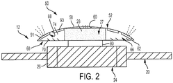
FIG. 2 depicts the heat dissipation system, in accordance with an aspect of an exemplary embodiment; -
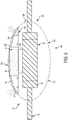
FIG. 3 depicts the heat dissipation system, in accordance with another aspect of an exemplary embodiment; -
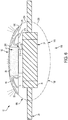
FIG. 4 depicts the heat dissipation system, in accordance with yet another aspect of an exemplary embodiment; -
FIG 5 depicts a heat dissipation system, in accordance with still yet another aspect of an exemplary embodiment; and -
FIG. 6 depicts a heat dissipation system, in accordance with another aspect of an exemplary embodiment. - A vertical takeoff and landing (VTOL) or rotary wing aircraft, in accordance with an exemplary embodiment, is generally indicated at 8 in
FIG. 1 .Rotary wing aircraft 8 including afuselage 10 that supports amain rotor system 12, which rotates about a main rotor axis R.Main rotor system 12 includes a plurality ofrotor blades 20 rotatable about a main rotor axis "R". Plurality ofrotor blades 20 is mounted to arotor hub 24. Each of the plurality ofrotor blades 20 may be connected to a corresponding one of a plurality of electromechanical actuators, one of which is indicated at 26 that form part of an individual blade control (IBC)system 27. - The IBC system typically includes a flight control computer (not shown) located in
fuselage 12 in addition to power andcontrol electronics 28 up atrotor hub 24. Power andcontrol electronics 28 convert flight control commands into signals that driveelectromechanical actuators 26 to adjust a position of each of the plurality ofrotor blades 20 through the air. In addition, it should be understood that power andcontrol electronics 28 may form part of a hub mounted vibration suppression (HMVS) system (not shown). The HMVS system reduces vibrations that may occurs due to operation of main rotor system. Details of the HMVS system may be found inU.S. Patent No. 8, 403,643 dated March 26, 2013 , incorporated herein by reference in its entirety.Main rotor system 12 is driven by agearbox 29 coupled to one or more prime movers, indicated generally at 30.Aircraft 8 includes an extendingtail 40 that supports atail rotor system 42 including a plurality of tail rotor blades, indicated generally at 44.Tail rotor system 42 may be operatively coupled togearbox 29 through a drive shaft (not shown). Aheat dissipation system 50 is mounted torotor hub 24 outwardly of the plurality ofrotor blades 30. - As shown in
FIG. 2 ,heat dissipation system 50 takes the form of anaerodynamic faring 52 having anouter surface 58, aninner surface 60 and an outerperimetric edge 62. As will be detailed herein, power andcontrol electronics 28 andelectromechanical actuators 26 generate heat. Further,rotor head 24 is enclosed inaerodynamic fairing 52 to maintain low drag thereby increasing flight efficiency at high speed.Aerodynamic fairing 52 blocks airflow and making heat removal difficult.Heat dissipation system 50 provides a mechanism for removing heat that may exist up inaerodynamic fairing 52. -
Inner surface 60 defines acomponent receiving zone 66. In accordance with an exemplary aspect,aerodynamic faring 52 includes acover member 68 that extends across outerperimetric edge 62.Cover member 68 may include one ormore vents 70 that define a circulatingair volume 74 incomponent receiving zone 66.Aerodynamic faring 52 is spaced fromrotor hub 24 through amounting flange 80. - In further accordance with an exemplary aspect, a plurality of electronic components indicated generally at 88 is mounted to
inner surface 60. Power andcontrol electronics 29 may also mounted toinner surface 60. It should be understood that plurality ofelectronic components 88 may be mounted directly toinner surface 60. In accordance with an exemplary aspect,electronic components 88 may include a packaging (not separately labeled) that closely conforms to surface profile (also not separately labeled) ofinner surface 60. Plurality ofelectronic components 88 may includepower components 91 andcontrol components 93.Power components 91 andcontrol components 93 may be operatively connected withelectromechanical actuators 26. Aerodynamic faring 52 promotes a heat exchange between the plurality ofelectronic components 88 and ambient. - At this point it should be understood that
heat dissipation system 50 may take on a variety of aerodynamic shapes and should not be limited to the particular shape shown. Further, various changes and/or modifications may be made to the heat dissipation system. For example, inFIG. 3 , wherein like reference numbers represent corresponding parts in the respective views, acover 100 is arranged across outerperimetric edge 62. Cover 100 does not include any openings and forms a trappedair volume 105 incomponent receiving zone 66. In accordance with another aspect, outerperimetric edge 66 may define anopening 110 as shown inFIG. 4 . - Other exemplary aspects are shown in
FIG. 5 wherein like reference numbers represent corresponding parts in the respective views. For example, aheat dissipation system 140 may include anaerodynamic fairing 142 having anupper portion 146 and alower portion 148 that interconnect to encapsulaterotor hub 24. Asurface 156 may extend acrossupper portion 146 to form acomponent receiving zone 160.Surface 156 may include one or more vents, one of which is indicated at 164.First openings 168 may be formed inupper portion 146 andsecond openings 170 may be formed inlower portion 170. First andsecond openings component receiving zone 160 viavents 164 to promote cooling ofpower components 91 andcontrol components 93. It should be understood that additional heat producing components could be arranged inlower portion 148. - Reference will now follow to
FIG. 6 , wherein like reference numbers represent corresponding parts in the respective views. A heat dissipation system, in accordance with another exemplary aspect, is indicated generally at 180.Heat dissipation system 180 includes anaerodynamic fairing 182 having anupper portion 186 and alower portion 188 that interconnect to encapsulaterotor hub 24. Asurface 196 may extend acrossupper portion 186 forming acomponent receiving zone 200.Upper portion 186 may includefirst openings 204 andlower portion 188 may includesecond openings 206. First andsecond openings aerodynamic fairing 182. - In the exemplary embodiment shown, a plurality of closed loop cooling passages, one of which is indicated at 214, is provided in
component receiving zone 200. Closedloop cooling passage 214 includes aninlet 216 and anoutlet 218 formed insurface 196. Closedloop cooling passage 214 guides fluid, such as air, intocomponent receiving zone 200 in proximity topower components 91 andcontrol components 93 to promote additional cooling. - While the present disclosure has been described in detail in connection with only a limited number of embodiments, it should be readily understood that the present disclosure is not limited to such disclosed embodiments. Rather, the present disclosure can be modified to incorporate any number of variations, alterations, substitutions or equivalent arrangements not heretofore described, but which are commensurate with the spirit and scope of the present disclosure. Additionally, while various embodiments of the present disclosure have been described, it is to be understood that aspects of the present disclosure may include only some of the described embodiments. Accordingly, the present disclosure is not to be seen as limited by the foregoing description, but is only limited by the scope of the appended claims.
Claims (15)
- A hub for a rotary wing aircraft comprising:a plurality of rotor blades;a heat dissipation system including an aerodynamic faring arranged outwardly of the hub, the aerodynamic fairing having an outer surface and an inner surface defining a component receiving zone; andan electronic component mounted to the inner surface of the aerodynamic faring in the component receiving zone.
- The hub according to claim 1, wherein the electronic component closely conforms to the inner surface of the aerodynamic faring.
- The hub according to claim 1 or 2, further comprising: a plurality of electromechanical actuators mounted to the hub and wherein the electronic component comprises a plurality of electronic components, each of the plurality of electromechanical actuators being operatively connected to a corresponding one of the plurality of electronic components.
- The hub according to claim 3, wherein each of the plurality of electromechanical actuators are operatively connected to a corresponding one of the plurality of rotor blades.
- The hub according to one of claims 1 - 4, further comprising: a cover member extending across the aerodynamic faring enclosing the component receiving zone.
- The hub according to claim 5, wherein the cover member creates a trapped air volume in the component receiving zone.
- The hub according to claim 5 or 6, wherein the cover member includes one or more vents forming a circulating air volume in the component receiving zone.
- The hub according to one of claims 1 - 7, wherein the aerodynamic faring is spaced from the hub through a mounting flange.
- A rotary wing aircraft comprising:a fuselage including an extending tail;a prime mover mounted to the fuselage;a gearbox mechanically connected to the prime mover; anda main rotor system mounted to the fuselage and mechanically connected to the gearbox, the main rotor system including a rotor hub, particularly according to one of the preceding claims, comprising:
a plurality of rotor blades;an aerodynamic faring arranged outwardly of the rotor hub, the aerodynamic fairing having an outer surface and an inner surface defining a component receiving zone; andan electronic component mounted to the inner surface of the aerodynamic faring in the component receiving zone. - The rotary wing aircraft according to claim 9, wherein the electronic component closely conforms to the inner surface of the aerodynamic faring.
- The rotary wing aircraft according to claim 9 or 10, further comprising: a plurality of electromechanical actuators mounted to the rotor hub and the electronic component comprises a plurality of electronic components, each of the plurality of electromechanical actuators being operatively connected to a corresponding one of the plurality of electronic components.
- The rotary wing aircraft according to claim 11, wherein each of the plurality of electromechanical actuators are operatively connected to a corresponding one of the plurality of rotor blades.
- The rotary wing aircraft according to one of claims 9 - 12, further comprising: a cover member extending across the aerodynamic faring enclosing the component receiving zone.
- The rotary wing aircraft according to claim 13, wherein the cover member creates a trapped air volume in the component receiving zone.
- The rotary wing aircraft according to claim 13 or 14, wherein the cover member includes one or more vents forming a circulating air volume in the component receiving zone.
Applications Claiming Priority (1)
| Application Number | Priority Date | Filing Date | Title |
|---|---|---|---|
| US16/043,806 US20200031459A1 (en) | 2018-07-24 | 2018-07-24 | Heat dissipation system for rotor mounted electronics |
Publications (1)
| Publication Number | Publication Date |
|---|---|
| EP3599158A1 true EP3599158A1 (en) | 2020-01-29 |
Family
ID=67297052
Family Applications (1)
| Application Number | Title | Priority Date | Filing Date |
|---|---|---|---|
| EP19186295.2A Withdrawn EP3599158A1 (en) | 2018-07-24 | 2019-07-15 | Heat dissipation system for rotor mounted electronics |
Country Status (2)
| Country | Link |
|---|---|
| US (1) | US20200031459A1 (en) |
| EP (1) | EP3599158A1 (en) |
Families Citing this family (1)
| Publication number | Priority date | Publication date | Assignee | Title |
|---|---|---|---|---|
| CN111204464A (en) * | 2020-03-13 | 2020-05-29 | 上海歌尔泰克机器人有限公司 | A fairing, an aircraft, and an aircraft cooling method |
Citations (9)
| Publication number | Priority date | Publication date | Assignee | Title |
|---|---|---|---|---|
| US4379678A (en) * | 1980-10-07 | 1983-04-12 | Textron, Inc. | Individual blade control |
| US5364230A (en) * | 1992-06-22 | 1994-11-15 | United Technologies Corporation | Rotor blade subassembly for a rotor assembly having ducted, coaxial counter-rotating rotors |
| WO2006127955A2 (en) * | 2005-05-26 | 2006-11-30 | Sikorsky Aircraft Corporation | De-rotation system for counter-rotating, coaxial rotor hub shaft fairing |
| US8403643B2 (en) | 2008-03-20 | 2013-03-26 | Sikorsky Aircraft Corporation | Dual frequency hub mounted vibration suppressor system |
| US20140091172A1 (en) * | 2005-04-14 | 2014-04-03 | Paul E. Arlton | Rotary wing vehicle |
| US20160090171A1 (en) * | 2014-09-26 | 2016-03-31 | Airbus Helicopters | Rotor fairing, a rotor, and an aircraft |
| US20160298544A1 (en) * | 2015-04-13 | 2016-10-13 | United Technologies Corporation | Thermal management system and method of circulating air in a gas turbine engine |
| US20180105263A1 (en) * | 2016-10-18 | 2018-04-19 | Sikorsky Aircraft Corporation | Electric propulsion system for a rotary wing aircraft |
| US20190017750A1 (en) * | 2017-07-11 | 2019-01-17 | Sikorsky Aircraft Corporation | Cooling system for rotor blade actuators |
-
2018
- 2018-07-24 US US16/043,806 patent/US20200031459A1/en not_active Abandoned
-
2019
- 2019-07-15 EP EP19186295.2A patent/EP3599158A1/en not_active Withdrawn
Patent Citations (9)
| Publication number | Priority date | Publication date | Assignee | Title |
|---|---|---|---|---|
| US4379678A (en) * | 1980-10-07 | 1983-04-12 | Textron, Inc. | Individual blade control |
| US5364230A (en) * | 1992-06-22 | 1994-11-15 | United Technologies Corporation | Rotor blade subassembly for a rotor assembly having ducted, coaxial counter-rotating rotors |
| US20140091172A1 (en) * | 2005-04-14 | 2014-04-03 | Paul E. Arlton | Rotary wing vehicle |
| WO2006127955A2 (en) * | 2005-05-26 | 2006-11-30 | Sikorsky Aircraft Corporation | De-rotation system for counter-rotating, coaxial rotor hub shaft fairing |
| US8403643B2 (en) | 2008-03-20 | 2013-03-26 | Sikorsky Aircraft Corporation | Dual frequency hub mounted vibration suppressor system |
| US20160090171A1 (en) * | 2014-09-26 | 2016-03-31 | Airbus Helicopters | Rotor fairing, a rotor, and an aircraft |
| US20160298544A1 (en) * | 2015-04-13 | 2016-10-13 | United Technologies Corporation | Thermal management system and method of circulating air in a gas turbine engine |
| US20180105263A1 (en) * | 2016-10-18 | 2018-04-19 | Sikorsky Aircraft Corporation | Electric propulsion system for a rotary wing aircraft |
| US20190017750A1 (en) * | 2017-07-11 | 2019-01-17 | Sikorsky Aircraft Corporation | Cooling system for rotor blade actuators |
Also Published As
| Publication number | Publication date |
|---|---|
| US20200031459A1 (en) | 2020-01-30 |
Similar Documents
| Publication | Publication Date | Title |
|---|---|---|
| EP3875374B1 (en) | Rotor system with an electric drive system line replaceable unit with integrated collective actuation | |
| EP3667875B1 (en) | Motor cooling system and method | |
| EP3876400B1 (en) | Electric drive system line replaceable unit with integrated thermal cooling | |
| EP3251952B1 (en) | Variable directional thrust for helicopter tail anti-torque system | |
| US8602347B2 (en) | Tilt rotor aircraft with fixed engine arrangement | |
| US8851415B1 (en) | Magnetic aerodynamic generation lift integrated flight technology with joint electric thrust | |
| EP3486170B1 (en) | Air management systems for stacked motor assemblies | |
| US10752343B2 (en) | Electric propulsion system for a rotary wing aircraft | |
| EP2796368B1 (en) | Integration of rotary electrical actuator for swashplateless individual blade control | |
| EP3281862B1 (en) | Rotorcraft variable thrust cross-flow fan systems | |
| US9045227B1 (en) | Dual fan aerodynamic lift device | |
| US20190023384A1 (en) | Electric powered direct drive rotor motor | |
| US20210061455A1 (en) | Anti-Torque Systems for Rotorcraft | |
| US20200156777A1 (en) | Anti-Torque Systems for Rotorcraft | |
| US11414184B2 (en) | Electric distributed propulsion with different rotor rotational speeds | |
| US10589855B2 (en) | Tiltrotor aircraft with outboard fixed engines | |
| EP3599158A1 (en) | Heat dissipation system for rotor mounted electronics | |
| EP3031720B1 (en) | Guide vanes for a pusher propeller for rotary wing aircraft | |
| EP3406521A1 (en) | Rotorcraft anti-torque and directional control using a centrifugal blower | |
| US20190310025A1 (en) | Cooling system for heat generating components in a fairing | |
| JP2024101529A (en) | Propulsion | |
| NZ767151B2 (en) | Ventilated rotor mounting boom for personal aircraft | |
| NZ767151A (en) | Ventilated rotor mounting boom for personal aircraft |
Legal Events
| Date | Code | Title | Description |
|---|---|---|---|
| PUAI | Public reference made under article 153(3) epc to a published international application that has entered the european phase |
Free format text: ORIGINAL CODE: 0009012 |
|
| AK | Designated contracting states |
Kind code of ref document: A1 Designated state(s): AL AT BE BG CH CY CZ DE DK EE ES FI FR GB GR HR HU IE IS IT LI LT LU LV MC MK MT NL NO PL PT RO RS SE SI SK SM TR |
|
| AX | Request for extension of the european patent |
Extension state: BA ME |
|
| STAA | Information on the status of an ep patent application or granted ep patent |
Free format text: STATUS: THE APPLICATION IS DEEMED TO BE WITHDRAWN |
|
| 18D | Application deemed to be withdrawn |
Effective date: 20200730 |