EP3598834A1 - Procédés permettant d'effectuer une transmission de sous-trames fractionnaires - Google Patents
Procédés permettant d'effectuer une transmission de sous-trames fractionnaires Download PDFInfo
- Publication number
- EP3598834A1 EP3598834A1 EP19195699.4A EP19195699A EP3598834A1 EP 3598834 A1 EP3598834 A1 EP 3598834A1 EP 19195699 A EP19195699 A EP 19195699A EP 3598834 A1 EP3598834 A1 EP 3598834A1
- Authority
- EP
- European Patent Office
- Prior art keywords
- subframe
- target position
- symbols
- potential
- control information
- Prior art date
- Legal status (The legal status is an assumption and is not a legal conclusion. Google has not performed a legal analysis and makes no representation as to the accuracy of the status listed.)
- Pending
Links
- 230000005540 biological transmission Effects 0.000 title claims abstract description 129
- 238000000034 method Methods 0.000 title claims abstract description 64
- 230000004044 response Effects 0.000 claims abstract description 21
- 238000001228 spectrum Methods 0.000 claims description 5
- 230000000737 periodic effect Effects 0.000 claims 2
- 238000004891 communication Methods 0.000 description 11
- 238000010586 diagram Methods 0.000 description 9
- 238000005516 engineering process Methods 0.000 description 8
- 230000011664 signaling Effects 0.000 description 7
- 230000008901 benefit Effects 0.000 description 3
- 238000001514 detection method Methods 0.000 description 3
- 230000006870 function Effects 0.000 description 3
- 230000007774 longterm Effects 0.000 description 3
- 238000012986 modification Methods 0.000 description 3
- 230000004048 modification Effects 0.000 description 3
- 230000001413 cellular effect Effects 0.000 description 2
- 230000002860 competitive effect Effects 0.000 description 2
- 238000004590 computer program Methods 0.000 description 2
- 238000000926 separation method Methods 0.000 description 2
- 101710116852 Molybdenum cofactor sulfurase 1 Proteins 0.000 description 1
- 230000006978 adaptation Effects 0.000 description 1
- 238000011161 development Methods 0.000 description 1
- 238000012545 processing Methods 0.000 description 1
- 239000004065 semiconductor Substances 0.000 description 1
- 238000012546 transfer Methods 0.000 description 1
Images


Classifications
-
- H—ELECTRICITY
- H04—ELECTRIC COMMUNICATION TECHNIQUE
- H04L—TRANSMISSION OF DIGITAL INFORMATION, e.g. TELEGRAPHIC COMMUNICATION
- H04L5/00—Arrangements affording multiple use of the transmission path
- H04L5/003—Arrangements for allocating sub-channels of the transmission path
-
- H—ELECTRICITY
- H04—ELECTRIC COMMUNICATION TECHNIQUE
- H04L—TRANSMISSION OF DIGITAL INFORMATION, e.g. TELEGRAPHIC COMMUNICATION
- H04L5/00—Arrangements affording multiple use of the transmission path
- H04L5/0001—Arrangements for dividing the transmission path
- H04L5/0014—Three-dimensional division
- H04L5/0023—Time-frequency-space
-
- H—ELECTRICITY
- H04—ELECTRIC COMMUNICATION TECHNIQUE
- H04L—TRANSMISSION OF DIGITAL INFORMATION, e.g. TELEGRAPHIC COMMUNICATION
- H04L5/00—Arrangements affording multiple use of the transmission path
- H04L5/003—Arrangements for allocating sub-channels of the transmission path
- H04L5/0048—Allocation of pilot signals, i.e. of signals known to the receiver
-
- H—ELECTRICITY
- H04—ELECTRIC COMMUNICATION TECHNIQUE
- H04L—TRANSMISSION OF DIGITAL INFORMATION, e.g. TELEGRAPHIC COMMUNICATION
- H04L5/00—Arrangements affording multiple use of the transmission path
- H04L5/003—Arrangements for allocating sub-channels of the transmission path
- H04L5/0053—Allocation of signaling, i.e. of overhead other than pilot signals
-
- H—ELECTRICITY
- H04—ELECTRIC COMMUNICATION TECHNIQUE
- H04W—WIRELESS COMMUNICATION NETWORKS
- H04W48/00—Access restriction; Network selection; Access point selection
- H04W48/08—Access restriction or access information delivery, e.g. discovery data delivery
- H04W48/12—Access restriction or access information delivery, e.g. discovery data delivery using downlink control channel
-
- H—ELECTRICITY
- H04—ELECTRIC COMMUNICATION TECHNIQUE
- H04W—WIRELESS COMMUNICATION NETWORKS
- H04W52/00—Power management, e.g. TPC [Transmission Power Control], power saving or power classes
- H04W52/02—Power saving arrangements
-
- H—ELECTRICITY
- H04—ELECTRIC COMMUNICATION TECHNIQUE
- H04W—WIRELESS COMMUNICATION NETWORKS
- H04W72/00—Local resource management
- H04W72/04—Wireless resource allocation
- H04W72/044—Wireless resource allocation based on the type of the allocated resource
- H04W72/0446—Resources in time domain, e.g. slots or frames
-
- H—ELECTRICITY
- H04—ELECTRIC COMMUNICATION TECHNIQUE
- H04W—WIRELESS COMMUNICATION NETWORKS
- H04W72/00—Local resource management
- H04W72/04—Wireless resource allocation
- H04W72/044—Wireless resource allocation based on the type of the allocated resource
- H04W72/0453—Resources in frequency domain, e.g. a carrier in FDMA
-
- H—ELECTRICITY
- H04—ELECTRIC COMMUNICATION TECHNIQUE
- H04W—WIRELESS COMMUNICATION NETWORKS
- H04W74/00—Wireless channel access
- H04W74/002—Transmission of channel access control information
-
- H—ELECTRICITY
- H04—ELECTRIC COMMUNICATION TECHNIQUE
- H04W—WIRELESS COMMUNICATION NETWORKS
- H04W74/00—Wireless channel access
- H04W74/08—Non-scheduled access, e.g. ALOHA
- H04W74/0808—Non-scheduled access, e.g. ALOHA using carrier sensing, e.g. carrier sense multiple access [CSMA]
-
- H—ELECTRICITY
- H04—ELECTRIC COMMUNICATION TECHNIQUE
- H04W—WIRELESS COMMUNICATION NETWORKS
- H04W74/00—Wireless channel access
- H04W74/08—Non-scheduled access, e.g. ALOHA
- H04W74/0808—Non-scheduled access, e.g. ALOHA using carrier sensing, e.g. carrier sense multiple access [CSMA]
- H04W74/0816—Non-scheduled access, e.g. ALOHA using carrier sensing, e.g. carrier sense multiple access [CSMA] with collision avoidance
-
- Y—GENERAL TAGGING OF NEW TECHNOLOGICAL DEVELOPMENTS; GENERAL TAGGING OF CROSS-SECTIONAL TECHNOLOGIES SPANNING OVER SEVERAL SECTIONS OF THE IPC; TECHNICAL SUBJECTS COVERED BY FORMER USPC CROSS-REFERENCE ART COLLECTIONS [XRACs] AND DIGESTS
- Y02—TECHNOLOGIES OR APPLICATIONS FOR MITIGATION OR ADAPTATION AGAINST CLIMATE CHANGE
- Y02D—CLIMATE CHANGE MITIGATION TECHNOLOGIES IN INFORMATION AND COMMUNICATION TECHNOLOGIES [ICT], I.E. INFORMATION AND COMMUNICATION TECHNOLOGIES AIMING AT THE REDUCTION OF THEIR OWN ENERGY USE
- Y02D30/00—Reducing energy consumption in communication networks
- Y02D30/70—Reducing energy consumption in communication networks in wireless communication networks
Definitions
- Embodiments of the present invention generally relate to communication techniques. More particularly, embodiments of the present invention relate to a method and apparatus for performing fractional subframe transmission.
- 3GPP 3rd Generation Partnership Project
- WLAN Wireless Local Area Network
- the multi-mode wireless communication technology has evolved to use multiple wireless communication technologies at the same time.
- the use of multiple wireless communication technologies simultaneously thereby increases transfer rates per unit time or improves the reliability of the terminal.
- a licensed band represents a frequency band that is exclusively licensed to a specific operator to provide specific wireless services.
- an unlicensed band represents a frequency band that is not allocated to a specific operator, but is opened so that all entities meeting the predefined requirements may use the frequency band.
- LBT Listen-Before-Talk
- channel bandwidth occupancy requirements For instance, an unlicensed band may be available at any time during a subframe.
- WLAN that uses Wireless Fidelity (WiFi) is the typical wireless communication technology used in the unlicensed band.
- Time granularity of current Long Term Evolution (LTE) is much larger than that of WiFi, which leads to the low competitive strength of License Assisted Access (LAA) with LBT.
- LAA License Assisted Access
- the present invention proposes a solution regarding fractional subframe transmission. Specifically, the present invention provides a method and apparatus for fractional subframe transmission with low signaling overhead and high resource utilization.
- embodiments of the invention provide a method for performing fractional subframe transmission.
- the method may comprise: in response to detecting that a channel becomes available, determining a target position from at least one potential position predefined in a subframe; and performing the fractional subframe transmission from the target position.
- the method may be performed at a transmitter.
- embodiments of the invention provide a method for performing fractional subframe transmission.
- the method may comprise: determining a target position from at least one potential position predefined in a subframe, the fractional subframe transmission starting at the target position; and receiving the fractional subframe transmission from the target position.
- the method may be performed at a receiver.
- embodiments of the invention provide an apparatus for performing fractional subframe transmission.
- the apparatus may comprise: a first determining unit configured to in response to detecting that a channel becomes available, determine a target position from at least one potential position predefined in a subframe; and a performing unit configured to perform the fractional subframe transmission from the target position.
- the apparatus may be implemented at a transmitter.
- embodiments of the invention provide an apparatus for performing fractional subframe transmission.
- the apparatus may comprise: a second determining unit configured to determine a target position from at least one potential position predefined in a subframe, the fractional subframe transmission starting at the target position; and a receiving unit configured to receive the fractional subframe transmission from the target position.
- the apparatus may be implemented at a receiver.
- Embodiments of the present invention are directed to a solution for performing fractional subframe transmission.
- the solution may be carried out between a receiver and a transmitter.
- the transmitter may determine a target position from at least one potential position predefined in a subframe and perform the fractional subframe transmission from the target position.
- the receiver may determine a target position from the at least one predefined potential position in a similar way and receive the fractional subframe transmission from the target position. In this way, transmission may be performed without introducing signalling overhead.
- the transmission may start from the current subframe, instead of the next subframe. As such, resource utilization is improved.
- a fractional subframe may refer to a subframe for downlink transmission or a subframe for uplink transmission, wherein one part of the fractional subframe is used for transmission of control information or data and the other part is not used for the transmission.
- a downlink subframe comprising 14 symbols, if only the last 6 symbols are available for in the downlink transmission while the first 8 symbols are unavailable, this subframe may be considered as a factional subframe.
- the fractional subframe transmission may refer to the transmission performed on one or more subframes, and at least one of the one or more subframes is a fractional subframe.
- the fractional subframe transmission may comprise various cases, such as the first subframe being a fractional subframe, the last subframe being a fractional subframe, both the first and the last subframes being fractional subframes, and the like.
- the fractional subframe transmission may be downlink or uplink cellular transmission.
- the receiver may comprise user equipment (UE), such as a terminal, a Mobile Terminal (MT), a Subscriber Station (SS), a Portable Subscriber Station (PSS), Mobile Station (MS), or an Access Terminal (AT).
- UE user equipment
- the transmitter may comprise a base station (BS), such as a node B (NodeB or NB), or an evolved NodeB (eNodeB or eNB).
- BS base station
- the transmitter may comprise a UE and the receiver may comprise a BS.
- the fractional subframe transmission may be D2D transmission.
- the receiver may be a Device-to-Device (D2D) receiver and the transmitter may be a D2D transmitter.
- D2D Device-to-Device
- Embodiments of the present invention may be applied in various communication systems, including but not limited to a Long Term Evolution (LTE) system or a Long Term Evolution Advanced (LTE-A) system.
- LTE Long Term Evolution
- LTE-A Long Term Evolution Advanced
- FIG. 1 illustrates a flow chart of a method 100 for performing fractional subframe transmission at a transmitter according to an embodiment of the invention.
- the method 100 may be performed at a transmitter, such as a BS, a D2D transmitter, and other suitable device.
- the method 100 starts at step S110, in which in response to detecting that a channel becomes available, a target position is determined from at least one potential position predefined in a subframe.
- a subframe may comprise a plurality of symbols.
- a subframe may be 1ms and comprise 14 symbols, for example, symbols 0 to 13.
- a position such as a potential position, a target position, a current position, a next position, may refer to a time point or a time period in the subframe.
- a position may correspond to an instant in a subframe.
- a position may correspond to a symbol of a subframe.
- the position may occupy a time period, for example, the time period of a symbol.
- a target position may refer to a position from which the fractional transmission may start
- a potential position may refer to a predefined position that is a candidate of the target position.
- each of the potential positions may correspond to a symbol of the subframe periodically or aperiodically.
- the potential positions may comprise every three symbols, for example, symbols 0, 3, 6, 9 and 12.
- each symbol in a subframe may be predefined as a potential position.
- the above examples are illustrated for example, rather than limitation. It can be appreciated that, in alternative embodiments, there may be aperiodic configurations of the potential positions.
- the potential positions may correspond to the symbols 0, 3, 8 and 12.
- Clear Chanel Assessment CCA
- eCCA Extended Clear Chanel Assessment
- the transmitter may detect whether a channel is available.
- the transmitter may determine the target position from one or more potential positions in several ways. In some embodiments, whether a current position is a potential position is detected first. If the current position is a potential position, the potential position may be determined as the target position; otherwise, a channel occupation signal may be transmitted from the current position until a potential position and then the potential position may be determined as the target position.
- the fractional subframe transmission is performed from the target position.
- the transmitter may send an indicator at the target position to a receiver.
- the indicator may indicate a size of control information of the fractional subframe transmission, for example, the number of symbols of Physical Downlink Control Channel (PDCCH).
- the indicator may be implemented as Physical Control Format Indicator Channel (PCFICH), or any other suitable indicator.
- PCFICH Physical Control Format Indicator Channel
- the receiver may know the size of the control information. For example, when the receiver detects PCFICH, it may have the knowledge of the number symbols of PDCCH. It is to be noted that the above example is shown only for illustration purpose, without suggesting any limitations on the scope of the subject matter described herein.
- the control information may be configured by higher layer signaling or configured according to specification(s).
- the transmitter may determine the number of available symbols in the subframe based on the target position, and transmit control information and data of the fractional subframe transmission from the target position based on the number of the available symbols.
- the control information may be transmitted on PDCCH
- the data may be transmitted on Physical Downlink Shared Channel (PDSCH). Details of the embodiments will be described with reference to FIG. 2 .
- the scheduling information associated with each of the potential position may be preconfigured in advance.
- the transmitter may obtain the preconfigured scheduling information associated with the target position, and perform the fractional subframe transmission based on the preconfigured scheduling information.
- the transmitter upon determining the target position, the transmitter does not have to spend much time on configuring scheduling information associated with the target position. In this way, the fractional subframe transmission may be performed more quickly and efficiently.
- FIG. 5 illustrates a schematic diagram 500 of fractional subframe transmission according to embodiments of the invention.
- FIG. 5 exemplarily shows four subframes, subframes 0 to 3.
- there are three potential positions 521, 522 and 523 wherein the first potential position 521 corresponds to the start of subframe 0, for example, symbol 0 of subframe 0.
- CCA/eCCA 501 may start from the first potential position 521.
- the transmitter may determine that the channel is available at a position 524. Since the position 524 is not a potential position, the transmitter may transmit channel occupation signals from the position 524 until a potential position, for example, the potential position 522, and determine the potential position 522 as the target position.
- the factional subframe transmission then may start from the target position, wherein control information may be transmitted on PDCCH at time periods 503, 505, 507 and 509, and data may be transmitted on PDSCH at time periods 504, 506, 508 and 510.
- FIG. 2 illustrates a flow chart of a method 200 for performing fractional subframe transmission at a transmitter according to another embodiment of the invention.
- the method 200 may be considered as a specific implementation of the method 100 described above with reference to Fig. 1 . However, it is noted that this is only for the purpose of illustrating the principles of the present invention, rather than limiting the scope thereof.
- Method 200 begins at step S210, in which a channel is detected as becoming available.
- whether a channel is available may be detected in several ways, such as energy detection, carrier sensing, and so on.
- strength of energy from a further transmitter may be measured on the channel.
- the further transmitter may be a transmitter that may use the same channel and is different from the transmitter performing the method according to embodiments of the present invention. If the energy strength is not strong, it may be determined that the channel is idle. In this regard, the energy strength may be compared with a strength threshold. In response to that the measured strength is less than the strength threshold, the channel may be determined as being available.
- the strength threshold may be a predetermined threshold, which may be set according to system requirements, specifications, channel quality, and so on.
- the strength threshold may be set as a fixed value or a value that is changed dynamically. It is to be understood that the above example embodiments are only for the purpose of illustration, without suggesting any limitations on the subject matter described herein.
- the strength threshold may be implemented in any other suitable ways.
- the channel availability may be detected based on carrier sensing.
- a signalling from a further transmitter may be detected on the channel.
- the further transmitter may be a transmitter that may use the channel and is different from the transmitter performing the method according to embodiments of the present invention. Based on the signalling, whether the channel is available may be determined.
- step S220 whether a current position is a potential position is detected.
- step S240 the potential position is determined as the target position. If the current position is not a potential position, the flow goes to step S230, where a channel occupation signal is transmitted from the current position until a potential position. Then, the flow goes to step S240, where the potential position is determined as the target position.
- a number of available symbols in the subframe are determined based on the target position.
- the number of available symbols may be determined based on the target position and the total number of symbols in a subframe. For way of example, if there are 14 symbols in one subframe, and if the target position corresponds to the sixth symbol, that is, symbol 5, it may be determined that there are 8 available symbols, i.e., symbols 6 to 13. For another example, if there are 12 symbols in one subframe, and if the target position corresponds to the eighth symbol, that is, symbol 7, it may be determined that there are 4 available symbols, i.e., symbols 8 to 11.
- control information and/or data of the fractional subframe transmission are transmitted from the target position based on the number of the available symbols.
- normal control information for example normal PDCCH
- shortened control information for example shortened PDCCH
- the normal PDCCH may occupy 3 symbols and the shortened PDCCH may occupy 1 or 2 symbols.
- the transmitter may transmit the control information and the data in the available symbols of the subframe and a subframe immediately following the subframe.
- the transmitter may transmit the control information in the available symbols of the subframe and transmit the data in a subframe immediately following the subframe.
- the transmitter may transmit a first part of the control information in the available symbols of the subframe and a second part of the control information in a further subframe immediately following the subframe, wherein the first part and the second part constitute the control information.
- the transmitter may transmit the data in the further subframe.
- the predetermined threshold may be set as a fixed value or a value that is changed dynamically, and may be configured by high layer signalling or prescribed by specifications. In an exemplary embodiment, the predetermined threshold may be set as 3.
- FIG. 6 illustrates a schematic diagram 600 of fractional subframe transmission according to embodiments of the invention.
- FIG. 6 exemplarily shows four subframes, subframes 0 to 3.
- CCA/eCCA 601 may start from the first potential position 621.
- the transmitter may determine that the channel is available at the potential position 622.
- the potential position 622 may be determined as the target position.
- the factional subframe transmission then may start from the target position, wherein control information may be transmitted on PDCCH at time periods 602, 603 and 605, and data may be transmitted on PDSCH at time periods 604 and 606. As shown in FIG.
- the control information is transmitted in the available symbols of the subframe 0 and its following subframe 1, corresponding to the time periods 602 and 603 respectively.
- the data is transmitted at the time period 604.
- the first part of the control information is transmitted at the time period 602, and the second part of the control information is transmitted at the time period 603.
- the factional subframe transmission may ends at a portion of a subframe or at a full subframe.
- the factional subframe transmission ends at a position 525.
- a portion of subframe 3 is used for the factional subframe transmission.
- both the first subframe (i.e., subframe 0) and the last subframe (i.e., subframe 3) are fractional subframes.
- the factional subframe transmission terminates at the end of subframe 2. In other words, the factional subframe transmission ends at a full subframe.
- a transport block size in the fractional subframe may be determined based on the number of the available symbols and the data of the transport block size may be transmitted in the subframe.
- the transport block size indicates the size of a data block to be transmitted in the fractional subframe transmission.
- the transport block size may be determined in various ways.
- the transmitter may determine a scaling factor associated with the number of the available symbols, and then determine the transport block size based on the scaling factor.
- the scaling factor may be defined in several ways. Table 1 illustrates an example of scaling factors associated with different numbers of available symbols. Table 1 Number of available symbols Scaling factor 1, 2, 3 N/A 4 0.25 5 0.25, 0.375 6 0.375 7 0.375, 0.5 8 0.5, 0.75 9, 10, 11, 12 0.75 13, 14 1
- the transmitter may use the available symbols to transmit control information of the fractional subframe transmission, and may determine that the available symbols are not enough for transmitting data after the transmission of the control information.
- the scaling factor may be designed as a value of "N/A", which indicates that the scaling factor is "not available”.
- the transmitter may determine that the associated scaling factor is 0.25.
- the transmitter may determine that the associated scaling factor is 0.25 or 0.375.
- the transmitter may determine that the associated scaling factor is 0.375.
- the transmitter may determine that the associated scaling factor is 0.375 or 0.5. In an exemplary embodiment, if the number of the available symbols is 8, the transmitter may determine that the associated scaling factor is 0.5 or 0.75. In an exemplary embodiment, if the number of the available symbols is 9, 10, 11 or 12, the transmitter may determine that the associated scaling factor is 0.75. In an exemplary embodiment, if the number of the available symbols is 13 or 14, the transmitter may determine that the associated scaling factor is 1.
- the transport block size may be determined based on the scaling factor in several ways.
- a first resource block number which indicates a number of resource blocks allocated for transmission may be obtained.
- the first resource block number may be determined by the transmitter in real time.
- a second resource block number may be determined based on the first resource block number and the scaling factor.
- the transport block size may be determined.
- a transport block size table may be used for determining the transport block size.
- Table 2 illustrates an exemplary transport block size table. Table 2 MCS 1 2 3 4 5 6 7 8 9 10 0 16 32 56 88 120 152 176 208 224 256 1 24 56 88 144 176 208 224 256 328 344 2 32 72 144 176 208 256 296 328 376 424 3 40 104 176 208 256 328 392 440 504 568 4 56 120 208 256 328 408 488 552 632 696 5 72 144 224 328 424 504 600 680 776 872 6 328 176 256 392 504 600 712 808 936 1032 7 104 224 328 472 584 712 840 968 1096 1224 8 120 256 392 536 680 808 968 1096 1256 1384 9 136 296 456 616 776 936 1096 12
- the horizontal direction of Table 2 may correspond to a resource block number, for example, the second resource block number in the embodiments, and the vertical direction may correspond to a Modulation and Coding Scheme (MCS).
- MCS Modulation and Coding Scheme
- the transmitter when the transmitter determines the second resource block number as well as the MCS that is employed currently, it may determine the transport block size by looking up the Table 2 based on the second resource block number and the MCS. By way of example, if the second resource block number is 8, and the MCS is 8 the transport block size may be determined as 1096.
- Table 2 is 10 ⁇ 27, it is simplification of 3GPP TS36.213 whose dimension is 34 ⁇ 110. It is further to be noted that the above example table is only for the purpose of illustration, without suggesting any limitations on the subject matter described herein. Any other suitable table may be used in the determination of the transport block size.
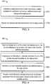
- FIG. 3 illustrates a flow chart of a method 300 for performing fractional subframe transmission at a receiver according to an embodiment of the invention.
- the method 300 may be performed at a receiver, such as a UE, a D2D receiver, and other suitable device.
- a target position is determined from at least one potential position predefined in a subframe, the fractional subframe transmission starting at the target position.
- a plurality of potential positions may periodically correspond to symbols of the subframe, for example according to equation (1).
- the potential positions may correspond to the symbols 3, 8 and 12.
- the target position indicates when the fractional subframe transmission starts.
- the transmitter may send an indicator at the target position to a receiver, wherein the indicator, for example PCFICH, may indicate a size of control information of the fractional subframe transmission.
- the target position may be indicated explicitly.
- the receiver it may detect the indicator at one of the at least one potential position, for example, denoted as potential position 1.
- the receiver may determine the one of the at least one potential position as the target position. Otherwise, the receiver may determine that this potential position is not the target position and carry out the same detection on a further potential position, for example potential position 2, and so on.
- the transmitter may not send the indicator.
- the receiver may make blind decoding for control information of the fractional subframe transmission at one of the at least one potential position.
- the receiver may determine the one of the at least one potential position as the target position.
- step S320 the fractional subframe transmission is received from the target position.
- the receiver may know the size of the control information and accordingly receive the control information from the target position.
- a number of available symbols in the subframe may be determined based on the target position, and the control information and data of the fractional subframe transmission may be received based on the number of the available symbols.
- the control information may be transmitted before the data.
- the receiver may receive control information prior to the data.
- it is possible that the data is transmitted before the control information. As such, the receiver may receive the data prior to the control information. Details will be discussion with reference to embodiments of FIG. 4 .
- FIG. 4 illustrates a flow chart of a method 400 for performing fractional subframe transmission at a receiver according to another embodiment of the invention.
- the method 400 may be considered as a specific implementation of the method 300 described above with reference to Fig. 3 . However, it is noted that this is only for the purpose of illustrating the principles of the present invention, rather than limiting the scope thereof.
- an indicator is detected at one of the at least one potential position, the indicator indicating a size of control information of the fractional subframe transmission.
- the transmitter may send an indicator, for example PCFICH, at the target position to a receiver, to indicate a size of control information of the fractional subframe transmission.
- the receiver may detect the indicator at one of the at least one potential position.
- the one of the at least one potential position is determined as the target position. Otherwise, the receiver may detect the indicator at a further potential position.
- a number of available symbols in the subframe is determined based on the target position.
- the number of available symbols may be determined based on the target position and the total number of symbols in a subframe. By way of example, if there are 14 symbols in one subframe, and if the target position corresponds to the sixth symbol, that is, symbol 5, it may be determined that there are 8 available symbols, i.e., symbols 6 to 13. For another example, if there are 12 symbols in one subframe, and if the target position corresponds to the eighth symbol, that is, symbol 7, it may be determined that there are 4 available symbols, i.e., symbols 8 to 11.
- control information and data of the fractional subframe transmission are received based on the number of the available symbols.
- the receiver may receive the control information and the data in the available symbols and a subframe immediately following the subframe. In an exemplary embodiment, if the number of the available symbols is equal to the size of the control information, the receiver may receive the control information in the available symbols of the subframe and receive the data in a subframe immediately following the subframe. In a further exemplary embodiment, if the number of the available symbols is less than the size of the control information, the receiver may receive a first part of the control information in the available symbols of the subframe and a second part of the control information in a further subframe immediately following the subframe, wherein the first part and the second part constitute the control information. After the control information is received, the receiver may receive the data in the further subframe.
- a transport block size in the subframe may be determined based on the number of the available symbols. Then, the data of the transport block size may be received in the subframe.
- the transport block size indicates the size of a data block to be transmitted in the fractional subframe transmission.
- the transport block size may be determined in various ways.
- the receiver may determine a scaling factor associated with the number of the available symbols, and then determine the transport block size based on the scaling factor.
- the scaling factor may be defined in several ways. As discussed above, Table 1 illustrates an example of scaling factors associated with different numbers of available symbols.
- the receiver may determine that there is no data transmitted and there is no need to determine the transport block size. In an exemplary embodiment, if the number of the available symbols is 4, the receiver may determine that the associated scaling factor is 0.25. In an exemplary embodiment, if the number of the available symbols is 5, the receiver may determine that the associated scaling factor is 0.25 or 0.375. In an exemplary embodiment, if the number of the available symbols is 6, the receiver may determine that the associated scaling factor is 0.375. In an exemplary embodiment, if the number of the available symbols is 7, the receiver may determine that the associated scaling factor is 0.375 or 0.5.
- the receiver may determine that the associated scaling factor is 0.5 or 0.75. In an exemplary embodiment, if the number of the available symbols is 9, 10, 11 or 12, the receiver may determine that the associated scaling factor is 0.75. In an exemplary embodiment, if the number of the available symbols is 13 or 14, the receiver may determine that the associated scaling factor is 1.
- the transport block size may be determined based on the scaling factor in several ways.
- a first resource block number which indicates a number of resource blocks allocated for transmission may be obtained.
- the first resource block number may be notified by the transmitter.
- a second resource block number may be determined based on the first resource block number and the scaling factor.
- the second resource block number may be determined according to equation (2).
- the transport block size may be determined.
- a transport block size table for example Table 2, may be used for determining the transport block size.
- the receiver determines the second resource block number as well as the MCS which is employed currently, it may determine the transport block size by looking up the Table 2.
- FIG. 7 illustrates a block diagram of an apparatus 700 for performing fractional subframe transmission according to embodiments of the invention.
- the apparatus 700 may be implemented at a transmitter, for example, a BS, a D2D transmitter or any other applicable device.
- the apparatus 700 comprises: a first determining unit 710 configured to in response to detecting that a channel becomes available, determine a target position from at least one potential position predefined in a subframe; and a performing unit 720 configured to perform the fractional subframe transmission from the target position.
- the first determining unit 710 may comprise: a potential position detecting unit configured to detect whether a current position is a potential position; and a first target position determining unit configured to responsive to that the current position is a potential position, determine the potential position as the target position, and responsive to that the current position is not a potential position, transmit a channel occupation signal from the current position until a potential position and determine the potential position as the target position.
- each of the at least one potential position may correspond to a symbol of the subframe periodically or aperiodically.
- the performing unit 720 may comprise: a sending unit configured to send an indicator at the target position, the indicator indicating a size of control information of the fractional subframe transmission.
- the performing unit 720 may comprise: a first available symbol number determining unit configured to determine a number of available symbols in the subframe based on the target position; and a transmitting unit configured to transmit control information and data of the fractional subframe transmission from the target position based on the number of the available symbols.
- the transmitting unit may be further configured to: responsive to the number of the available symbols is less than or equal to a predetermined threshold, transmit the control information and the data in the available symbols and a subframe immediately following the subframe.
- the transmitting unit may comprise: a size determining unit configured to determine a transport block size in the subframe based on the number of the available symbols, wherein the transmitting unit may be further configured to transmit the data of the transport block size in the subframe.
- the performing unit 720 may comprise: a scheduling information obtaining unit configured to obtain preconfigured scheduling information associated with the target position, wherein the performing unit may be further configured to perform the fractional subframe transmission based on the preconfigured scheduling information.
- FIG. 8 illustrates a block diagram of an apparatus 800 for performing fractional subframe transmission according to embodiments of the invention.
- the apparatus 800 may be implemented at a receiver, for example, a cellular UE, a D2D receiver or any other applicable device.
- the apparatus 800 comprises: a second determining unit 810 configured to determine a target position from at least one potential position predefined in a subframe, the fractional subframe transmission starting at the target position; and a receiving unit 820 configured to receive the fractional subframe transmission from the target position.
- the second determining unit 810 may comprise: an indicator detecting unit configured to detect an indicator at one of the at least one potential position, the indicator indicating a size of control information of the fractional subframe transmission; and a second target position determining unit configured to in response to that the indicator is detected, determine the one of the at least one potential position as the target position.
- the second determining unit 810 may comprise: a decoding unit configured to make blind decoding for control information of the fractional subframe transmission at one of the at least one potential position; and a third target position determining unit configured to in response to that the blind decoding is success, determine the one of the at least one potential position as the target position.
- each of the at least one potential position may correspond to a symbol of the subframe periodically or aperiodically.
- the receiving unit 820 may comprise: a second available symbol number determining unit configured to determine a number of available symbols in the subframe based on the target position, wherein the receiving unit may be further configured to receive control information and data of the fractional subframe transmission based on the number of the available symbols.
- the receiving unit 820 may be further configured to responsive to the number of the available symbols is less than or equal to a predetermined threshold, receive the control information and the data in the available symbols and a subframe immediately following the subframe.
- the receiving unit 820 may comprise: a size determining unit configured to determine a transport block size in the subframe based on the number of the available symbols, wherein the receiving unit may be further configured to receive the data of the transport block size in the subframe.
- apparatuses 700 and 800 may be respectively implemented by any suitable technique either known at present or developed in the future. Further, a single device shown in FIG. 7 or FIG. 8 may be alternatively implemented in multiple devices separately, and multiple separated devices may be implemented in a single device. The scope of the present invention is not limited in these regards.
- the apparatus 700 may be configured to implement functionalities as described with reference to FIGs.1-2
- the apparatus 800 may be configured to implement functionalities as described with reference to FIGs. 3-4 . Therefore, the features discussed with respect to the method 100 or 200 may apply to the corresponding components of the apparatus 700, and the features discussed with respect to the method 300 or 400 may apply to the corresponding components of the apparatus 800.
- the components of the apparatus 700 or the apparatus 800 may be embodied in hardware, software, firmware, and/or any combination thereof.
- the components of the apparatus 700 or the apparatus 800 may be respectively implemented by a circuit, a processor or any other appropriate device. Those skilled in the art will appreciate that the aforesaid examples are only for illustration not limitation.
- the apparatus 700 or the apparatus 800 may comprise at least one processor.
- the at least one processor suitable for use with embodiments of the present disclosure may include, by way of example, both general and special purpose processors already known or developed in the future.
- the apparatus 700 or the apparatus 800 may further comprise at least one memory.
- the at least one memory may include, for example, semiconductor memory devices, e.g., RAM, ROM, EPROM, EEPROM, and flash memory devices.
- the at least one memory may be used to store program of computer executable instructions.
- the program can be written in any high-level and/or low-level compliable or interpretable programming languages.
- the computer executable instructions may be configured, with the at least one processor, to cause the apparatus 700 to at least perform according to the method 100 or 200 as discussed above, or to cause the apparatus 800 to at least perform according to the method 300 or 400 as discussed above.
- the present disclosure may be embodied in an apparatus, a method, or a computer program product.
- the various exemplary embodiments may be implemented in hardware or special purpose circuits, software, logic or any combination thereof.
- some aspects may be implemented in hardware, while other aspects may be implemented in firmware or software which may be executed by a controller, microprocessor or other computing device, although the disclosure is not limited thereto.
- FIGs. 1-4 may be viewed as method steps, and/or as operations that result from operation of computer program code, and/or as a plurality of coupled logic circuit elements constructed to carry out the associated function(s).
- At least some aspects of the exemplary embodiments of the disclosures may be practiced in various components such as integrated circuit chips and modules, and that the exemplary embodiments of this disclosure may be realized in an apparatus that is embodied as an integrated circuit, FPGA or ASIC that is configurable to operate in accordance with the exemplary embodiments of the present disclosure.
Landscapes
- Engineering & Computer Science (AREA)
- Signal Processing (AREA)
- Computer Networks & Wireless Communication (AREA)
- Computer Security & Cryptography (AREA)
- Mobile Radio Communication Systems (AREA)
- Dc Digital Transmission (AREA)
Priority Applications (1)
| Application Number | Priority Date | Filing Date | Title |
|---|---|---|---|
| EP19195699.4A EP3598834A1 (fr) | 2015-01-30 | 2015-01-30 | Procédés permettant d'effectuer une transmission de sous-trames fractionnaires |
Applications Claiming Priority (3)
| Application Number | Priority Date | Filing Date | Title |
|---|---|---|---|
| EP19195699.4A EP3598834A1 (fr) | 2015-01-30 | 2015-01-30 | Procédés permettant d'effectuer une transmission de sous-trames fractionnaires |
| PCT/CN2015/071898 WO2016119192A1 (fr) | 2015-01-30 | 2015-01-30 | Procédé et appareil pour l'exécution de transmission de sous-trame fractionnelle |
| EP15879400.8A EP3105975B1 (fr) | 2015-01-30 | 2015-01-30 | Procédé et appareil pour l'exécution de transmission de sous-trame fractionnelle |
Related Parent Applications (1)
| Application Number | Title | Priority Date | Filing Date |
|---|---|---|---|
| EP15879400.8A Division EP3105975B1 (fr) | 2015-01-30 | 2015-01-30 | Procédé et appareil pour l'exécution de transmission de sous-trame fractionnelle |
Publications (1)
| Publication Number | Publication Date |
|---|---|
| EP3598834A1 true EP3598834A1 (fr) | 2020-01-22 |
Family
ID=56542188
Family Applications (2)
| Application Number | Title | Priority Date | Filing Date |
|---|---|---|---|
| EP15879400.8A Active EP3105975B1 (fr) | 2015-01-30 | 2015-01-30 | Procédé et appareil pour l'exécution de transmission de sous-trame fractionnelle |
| EP19195699.4A Pending EP3598834A1 (fr) | 2015-01-30 | 2015-01-30 | Procédés permettant d'effectuer une transmission de sous-trames fractionnaires |
Family Applications Before (1)
| Application Number | Title | Priority Date | Filing Date |
|---|---|---|---|
| EP15879400.8A Active EP3105975B1 (fr) | 2015-01-30 | 2015-01-30 | Procédé et appareil pour l'exécution de transmission de sous-trame fractionnelle |
Country Status (8)
| Country | Link |
|---|---|
| US (6) | US9888497B2 (fr) |
| EP (2) | EP3105975B1 (fr) |
| JP (1) | JP6531765B2 (fr) |
| CN (2) | CN106416383B (fr) |
| CA (1) | CA2943557C (fr) |
| ES (1) | ES2763379T3 (fr) |
| RU (1) | RU2669363C2 (fr) |
| WO (1) | WO2016119192A1 (fr) |
Families Citing this family (7)
| Publication number | Priority date | Publication date | Assignee | Title |
|---|---|---|---|---|
| DE112015006876T5 (de) * | 2015-09-04 | 2018-05-30 | Intel Corporation | Pusch-Uplink ohne Autorisierung |
| WO2018030938A1 (fr) | 2016-08-12 | 2018-02-15 | Telefonaktiebolaget Lm Ericsson (Publ) | Indexation de ressources de sous-trames dans une communication de dispositif à dispositif (d2d) |
| KR20190068611A (ko) | 2016-10-21 | 2019-06-18 | 텔레호낙티에볼라게트 엘엠 에릭슨(피유비엘) | 다운링크 제어 채널들과 비주기적인 채널 상태 정보-기준 신호들 사이의 충돌 회피 |
| EP3688901A1 (fr) | 2017-09-29 | 2020-08-05 | Telefonaktiebolaget LM Ericsson (PUBL) | Configuration de taille de bloc de transport |
| MX2020001558A (es) * | 2018-02-28 | 2020-03-20 | Guangdong Oppo Mobile Telecommunications Corp Ltd | Metodo para correlacionar simbolos de modulacion en unidades de recursos de subtrama de asignacion. |
| US11943749B2 (en) * | 2018-08-01 | 2024-03-26 | Lenovo (Beijing) Limited | Method of transmitting data over indicated resource blocks |
| CN111263469B (zh) * | 2019-01-18 | 2022-02-15 | 维沃移动通信有限公司 | 确定参数值的方法和设备 |
Citations (2)
| Publication number | Priority date | Publication date | Assignee | Title |
|---|---|---|---|---|
| US20110103315A1 (en) * | 2009-10-30 | 2011-05-05 | Sony Ericsson Mobile Communications Ab | Coordinated Signaling of Scheduling Information for Uplink and Downlink Communications |
| US20140341135A1 (en) * | 2013-05-20 | 2014-11-20 | Qualcomm Incoporated | Collision avoidance scheme for wireless communications over unlicensed spectrum |
Family Cites Families (39)
| Publication number | Priority date | Publication date | Assignee | Title |
|---|---|---|---|---|
| US8576807B2 (en) * | 2007-06-25 | 2013-11-05 | Qualcomm Incorporated | Channel interleaving structure for a wireless communication system |
| KR100904533B1 (ko) * | 2008-01-11 | 2009-06-25 | 엘지전자 주식회사 | 전송 타이밍 조절 방법, 연속적인 패킷 전송 방법 및 이동통신 단말 |
| KR101643258B1 (ko) | 2009-05-18 | 2016-07-27 | 삼성전자 주식회사 | Lte 시스템에서 자원 할당 방법 |
| US8457079B2 (en) * | 2009-10-05 | 2013-06-04 | Motorola Mobility Llc | Method and apparatus for mitigating downlink control channel interference |
| US8681686B2 (en) | 2010-01-29 | 2014-03-25 | Panasonic Corporation | Terminal device and interference removal method |
| WO2012022370A2 (fr) * | 2010-08-16 | 2012-02-23 | Nokia Siemens Networks Oy | Planification de porteuses de composantes |
| CN101931501B (zh) * | 2010-08-27 | 2016-06-29 | 中兴通讯股份有限公司 | 一种确定传输块大小的方法及装置 |
| US9252930B2 (en) | 2011-01-07 | 2016-02-02 | Futurewei Technologies, Inc. | Reference signal transmission and reception method and equipment |
| WO2012124924A2 (fr) * | 2011-03-11 | 2012-09-20 | 엘지전자 주식회사 | Procédé et dispositif permettant à un terminal de transmettre et de recevoir un signal dans un système de communication sans fil soumis à une technique d'agrégation de porteuses |
| CN102740473B (zh) * | 2011-04-08 | 2017-12-01 | 中兴通讯股份有限公司 | 一种下行控制信息的处理方法和系统 |
| EP2701320B1 (fr) * | 2011-04-19 | 2019-11-27 | LG Electronics Inc. | Procédé permettant de transmettre des informations de commande dans un système de communication sans fil et dispositif associé |
| WO2012148236A2 (fr) * | 2011-04-28 | 2012-11-01 | 엘지전자 주식회사 | Procédé et appareil pour la transmission de signaux de synchronisation dans un système d'agrégation de porteuses |
| WO2012173570A1 (fr) * | 2011-06-17 | 2012-12-20 | Telefonaktiebolaget L M Ericsson (Publ) | Dispositif sans fil, nœud de réseau et procédés associés |
| US9854446B2 (en) | 2011-07-07 | 2017-12-26 | Lg Electronics Inc. | Method and apparatus for transmitting a signal in a wireless communication system |
| US8873467B2 (en) * | 2011-12-05 | 2014-10-28 | Ofinno Technologies, Llc | Control channel detection |
| US20130142062A1 (en) * | 2011-12-05 | 2013-06-06 | Esmael Hejazi Dinan | Channel State Information Feedback |
| JP6127146B2 (ja) | 2012-09-28 | 2017-05-10 | インターデイジタル パテント ホールディングス インコーポレイテッド | 多次元アンテナ構成を使用する無線通信 |
| KR102157651B1 (ko) | 2012-10-04 | 2020-09-18 | 엘지전자 주식회사 | 무선 통신 시스템에서 안테나 포트 관계를 고려한 하향링크 신호 송수신 방법 및 장치 |
| JP6336455B2 (ja) | 2012-10-04 | 2018-06-06 | エルジー エレクトロニクス インコーポレイティド | 無線通信システムにおいてアンテナポート関係を考慮した下りリンク信号送受信方法及び装置 |
| KR102019815B1 (ko) | 2013-02-05 | 2019-09-10 | 주식회사 팬택 | 단말, 단말의 채널 상태 정보를 위한 기준 신호 수신 방법, 기지국, 및 기지국의 채널 상태 정보를 위한 기준 신호 전송 방법 |
| JP6302457B2 (ja) * | 2013-03-08 | 2018-03-28 | シャープ株式会社 | 端末、基地局、通信システムおよび通信方法 |
| CN104113914B (zh) * | 2013-04-17 | 2019-04-19 | 中兴通讯股份有限公司 | 一种物理多播信道的配置、发送和接收方法及系统 |
| CN104243115B (zh) * | 2013-06-07 | 2017-08-25 | 电信科学技术研究院 | 物理多播信道传输方法和设备 |
| JP6114153B2 (ja) | 2013-09-26 | 2017-04-12 | 株式会社Nttドコモ | 基地局、移動局、参照信号送信方法及びチャネル品質測定方法 |
| US9332465B2 (en) * | 2013-10-15 | 2016-05-03 | Qualcomm Incorporated | Long term evolution interference management in unlicensed bands for wi-fi operation |
| US9681325B2 (en) * | 2013-12-19 | 2017-06-13 | Qualcomm Incorporated | Channel and interference measurement in LTE/LTE-A networks including unlicensed spectrum |
| CN105162563B (zh) * | 2014-08-25 | 2020-07-10 | 中兴通讯股份有限公司 | 非授权载波信息的发送及接收的方法和装置 |
| US9420584B2 (en) * | 2014-09-17 | 2016-08-16 | Telefonaktiebolaget Lm Ericsson (Publ) | Uplink sounding reference signals for machine type communications (MTC) user equipment (UE) |
| US20160095114A1 (en) * | 2014-09-26 | 2016-03-31 | Electronics And Telecommunications Research Institute | Method and apparatus for managing allocation and usage of radio resource, method and apparatus for transmitting data through unlicensed band channel, and method and apparatus for managing access of radio resource |
| EP3214889B1 (fr) * | 2014-10-31 | 2020-09-23 | Samsung Electronics Co., Ltd. | Procédé et appareil de communication au moyen d'une bande sans licence dans un système de communications mobiles |
| US9326157B1 (en) * | 2014-11-06 | 2016-04-26 | Intel IP Corporation | Subframe aligned listen-before-talk for cellular in unlicensed band |
| US10129872B2 (en) * | 2014-12-15 | 2018-11-13 | Qualcomm Incorporated | Misdetection of fractional channel reserving signals |
| EP3664354B1 (fr) * | 2014-12-23 | 2021-10-20 | LG Electronics Inc. | Procédé de configuration et de programmation d'une sous-trame partielle dans un système d'accès sans fil prenant en charge une bande sans licence et dispositif de prise en charge associé |
| EP3251317A4 (fr) * | 2015-01-29 | 2018-09-19 | Intel IP Corporation | Dispositif et procédé pour une utilisation efficace d'un spectre sans licence |
| JP2016174216A (ja) * | 2015-03-16 | 2016-09-29 | 株式会社Nttドコモ | 無線基地局、ユーザ端末、無線通信システムおよび無線通信方法 |
| US10652753B2 (en) * | 2015-07-24 | 2020-05-12 | Samsung Electronics Co., Ltd. | Method for transmitting control signal and channel in mobile communication system using unlicensed band |
| WO2017030310A1 (fr) * | 2015-08-14 | 2017-02-23 | 한국전자통신연구원 | Procédé de fonctionnement d'un nœud de communication dans un réseau prenant en charges des bandes sous licence et sans licence |
| US9781603B1 (en) | 2016-10-20 | 2017-10-03 | Fortress Cyber Security, LLC | Combined network and physical security appliance |
| JP6555396B2 (ja) | 2018-07-05 | 2019-08-07 | 日本電気株式会社 | ユーザ装置及び基地局によって行われる方法 |
-
2015
- 2015-01-30 CA CA2943557A patent/CA2943557C/fr active Active
- 2015-01-30 EP EP15879400.8A patent/EP3105975B1/fr active Active
- 2015-01-30 CN CN201580030376.XA patent/CN106416383B/zh active Active
- 2015-01-30 CN CN201911126308.XA patent/CN110809311B/zh active Active
- 2015-01-30 ES ES15879400T patent/ES2763379T3/es active Active
- 2015-01-30 US US15/302,817 patent/US9888497B2/en active Active
- 2015-01-30 JP JP2016564159A patent/JP6531765B2/ja active Active
- 2015-01-30 EP EP19195699.4A patent/EP3598834A1/fr active Pending
- 2015-01-30 RU RU2016141273A patent/RU2669363C2/ru active
- 2015-01-30 WO PCT/CN2015/071898 patent/WO2016119192A1/fr active Application Filing
-
2017
- 2017-07-07 US US15/644,147 patent/US10063356B2/en active Active
-
2018
- 2018-07-20 US US16/041,313 patent/US10771206B2/en active Active
-
2020
- 2020-07-13 US US16/927,525 patent/US11159285B2/en active Active
-
2021
- 2021-09-23 US US17/483,130 patent/US11764917B2/en active Active
-
2023
- 2023-07-27 US US18/227,086 patent/US12074811B2/en active Active
Patent Citations (2)
| Publication number | Priority date | Publication date | Assignee | Title |
|---|---|---|---|---|
| US20110103315A1 (en) * | 2009-10-30 | 2011-05-05 | Sony Ericsson Mobile Communications Ab | Coordinated Signaling of Scheduling Information for Uplink and Downlink Communications |
| US20140341135A1 (en) * | 2013-05-20 | 2014-11-20 | Qualcomm Incoporated | Collision avoidance scheme for wireless communications over unlicensed spectrum |
Non-Patent Citations (1)
| Title |
|---|
| QUALCOMM INCORPORATED: "Solutions for required functionalities and design targets", vol. RAN WG1, no. Ljubljana, Slovenia; 20141006 - 20141010, 27 September 2014 (2014-09-27), XP050869665, Retrieved from the Internet <URL:http://www.3gpp.org/ftp/tsg_ran/WG1_RL1/TSGR1_78b/Docs/> [retrieved on 20140927] * |
Also Published As
| Publication number | Publication date |
|---|---|
| EP3105975A1 (fr) | 2016-12-21 |
| US11764917B2 (en) | 2023-09-19 |
| US20220038223A1 (en) | 2022-02-03 |
| US20190007178A1 (en) | 2019-01-03 |
| US12074811B2 (en) | 2024-08-27 |
| US20170325261A1 (en) | 2017-11-09 |
| EP3105975A4 (fr) | 2017-11-01 |
| CN110809311A (zh) | 2020-02-18 |
| US20200344014A1 (en) | 2020-10-29 |
| JP2017518675A (ja) | 2017-07-06 |
| US10771206B2 (en) | 2020-09-08 |
| CN106416383B (zh) | 2019-12-13 |
| US10063356B2 (en) | 2018-08-28 |
| US20240022364A1 (en) | 2024-01-18 |
| CN110809311B (zh) | 2023-02-28 |
| CA2943557C (fr) | 2022-08-16 |
| CA2943557A1 (fr) | 2016-08-04 |
| EP3105975B1 (fr) | 2019-10-02 |
| US9888497B2 (en) | 2018-02-06 |
| CN106416383A (zh) | 2017-02-15 |
| US11159285B2 (en) | 2021-10-26 |
| JP6531765B2 (ja) | 2019-06-19 |
| ES2763379T3 (es) | 2020-05-28 |
| WO2016119192A1 (fr) | 2016-08-04 |
| US20170317793A1 (en) | 2017-11-02 |
| RU2669363C2 (ru) | 2018-10-12 |
| RU2016141273A (ru) | 2018-04-20 |
Similar Documents
| Publication | Publication Date | Title |
|---|---|---|
| US12074811B2 (en) | Method and apparatus for performing fractional subframe transmission | |
| JP6555396B2 (ja) | ユーザ装置及び基地局によって行われる方法 | |
| US11856563B2 (en) | Method and apparatus for performing fractional subframe transmission | |
| JP2022153523A (ja) | ユーザ装置、基地局、ユーザ装置によって実行される方法、及び基地局によって実行される方法 | |
| JP7111215B2 (ja) | 基地局及びユーザ装置により実行される方法 | |
| WO2016119193A1 (fr) | Procédé et appareil permettant d'exécuter une transmission sur sous-trame fractionnée | |
| CN112135365B (zh) | 用于执行部分子帧传输的方法和装置 |
Legal Events
| Date | Code | Title | Description |
|---|---|---|---|
| PUAI | Public reference made under article 153(3) epc to a published international application that has entered the european phase |
Free format text: ORIGINAL CODE: 0009012 |
|
| STAA | Information on the status of an ep patent application or granted ep patent |
Free format text: STATUS: REQUEST FOR EXAMINATION WAS MADE |
|
| 17P | Request for examination filed |
Effective date: 20190905 |
|
| AC | Divisional application: reference to earlier application |
Ref document number: 3105975 Country of ref document: EP Kind code of ref document: P |
|
| AK | Designated contracting states |
Kind code of ref document: A1 Designated state(s): AL AT BE BG CH CY CZ DE DK EE ES FI FR GB GR HR HU IE IS IT LI LT LU LV MC MK MT NL NO PL PT RO RS SE SI SK SM TR |
|
| RBV | Designated contracting states (corrected) |
Designated state(s): AL AT BE BG CH CY CZ DE DK EE ES FI FR GB GR HR HU IE IS IT LI LT LU LV MC MK MT NL NO PL PT RO RS SE SI SK SM TR |
|
| STAA | Information on the status of an ep patent application or granted ep patent |
Free format text: STATUS: EXAMINATION IS IN PROGRESS |
|
| 17Q | First examination report despatched |
Effective date: 20210705 |
|
| GRAP | Despatch of communication of intention to grant a patent |
Free format text: ORIGINAL CODE: EPIDOSNIGR1 |
|
| STAA | Information on the status of an ep patent application or granted ep patent |
Free format text: STATUS: GRANT OF PATENT IS INTENDED |
|
| RIC1 | Information provided on ipc code assigned before grant |
Ipc: H04W 74/0808 20240101ALI20240318BHEP Ipc: H04W 52/02 20090101ALI20240318BHEP Ipc: H04W 74/00 20090101AFI20240318BHEP |
|
| INTG | Intention to grant announced |
Effective date: 20240422 |
|
| GRAS | Grant fee paid |
Free format text: ORIGINAL CODE: EPIDOSNIGR3 |
|
| GRAA | (expected) grant |
Free format text: ORIGINAL CODE: 0009210 |
|
| STAA | Information on the status of an ep patent application or granted ep patent |
Free format text: STATUS: THE PATENT HAS BEEN GRANTED |