EP3598705B1 - Routingsteuerung - Google Patents
Routingsteuerung Download PDFInfo
- Publication number
- EP3598705B1 EP3598705B1 EP18790554.2A EP18790554A EP3598705B1 EP 3598705 B1 EP3598705 B1 EP 3598705B1 EP 18790554 A EP18790554 A EP 18790554A EP 3598705 B1 EP3598705 B1 EP 3598705B1
- Authority
- EP
- European Patent Office
- Prior art keywords
- vtep device
- route
- host
- evpn
- vtep
- Prior art date
- Legal status (The legal status is an assumption and is not a legal conclusion. Google has not performed a legal analysis and makes no representation as to the accuracy of the status listed.)
- Active
Links
Images


Classifications
-
- H—ELECTRICITY
- H04—ELECTRIC COMMUNICATION TECHNIQUE
- H04L—TRANSMISSION OF DIGITAL INFORMATION, e.g. TELEGRAPHIC COMMUNICATION
- H04L45/00—Routing or path finding of packets in data switching networks
- H04L45/02—Topology update or discovery
-
- H—ELECTRICITY
- H04—ELECTRIC COMMUNICATION TECHNIQUE
- H04L—TRANSMISSION OF DIGITAL INFORMATION, e.g. TELEGRAPHIC COMMUNICATION
- H04L12/00—Data switching networks
- H04L12/28—Data switching networks characterised by path configuration, e.g. LAN [Local Area Networks] or WAN [Wide Area Networks]
- H04L12/46—Interconnection of networks
- H04L12/4641—Virtual LANs, VLANs, e.g. virtual private networks [VPN]
-
- H—ELECTRICITY
- H04—ELECTRIC COMMUNICATION TECHNIQUE
- H04L—TRANSMISSION OF DIGITAL INFORMATION, e.g. TELEGRAPHIC COMMUNICATION
- H04L45/00—Routing or path finding of packets in data switching networks
- H04L45/02—Topology update or discovery
- H04L45/028—Dynamic adaptation of the update intervals, e.g. event-triggered updates
-
- H—ELECTRICITY
- H04—ELECTRIC COMMUNICATION TECHNIQUE
- H04L—TRANSMISSION OF DIGITAL INFORMATION, e.g. TELEGRAPHIC COMMUNICATION
- H04L45/00—Routing or path finding of packets in data switching networks
- H04L45/42—Centralised routing
-
- H—ELECTRICITY
- H04—ELECTRIC COMMUNICATION TECHNIQUE
- H04L—TRANSMISSION OF DIGITAL INFORMATION, e.g. TELEGRAPHIC COMMUNICATION
- H04L45/00—Routing or path finding of packets in data switching networks
- H04L45/64—Routing or path finding of packets in data switching networks using an overlay routing layer
-
- H—ELECTRICITY
- H04—ELECTRIC COMMUNICATION TECHNIQUE
- H04L—TRANSMISSION OF DIGITAL INFORMATION, e.g. TELEGRAPHIC COMMUNICATION
- H04L45/00—Routing or path finding of packets in data switching networks
- H04L45/66—Layer 2 routing, e.g. in Ethernet based MAN's
-
- H—ELECTRICITY
- H04—ELECTRIC COMMUNICATION TECHNIQUE
- H04L—TRANSMISSION OF DIGITAL INFORMATION, e.g. TELEGRAPHIC COMMUNICATION
- H04L47/00—Traffic control in data switching networks
- H04L47/70—Admission control; Resource allocation
- H04L47/82—Miscellaneous aspects
- H04L47/825—Involving tunnels, e.g. MPLS
-
- H—ELECTRICITY
- H04—ELECTRIC COMMUNICATION TECHNIQUE
- H04L—TRANSMISSION OF DIGITAL INFORMATION, e.g. TELEGRAPHIC COMMUNICATION
- H04L63/00—Network architectures or network communication protocols for network security
- H04L63/02—Network architectures or network communication protocols for network security for separating internal from external traffic, e.g. firewalls
- H04L63/0272—Virtual private networks
-
- H—ELECTRICITY
- H04—ELECTRIC COMMUNICATION TECHNIQUE
- H04L—TRANSMISSION OF DIGITAL INFORMATION, e.g. TELEGRAPHIC COMMUNICATION
- H04L63/00—Network architectures or network communication protocols for network security
- H04L63/02—Network architectures or network communication protocols for network security for separating internal from external traffic, e.g. firewalls
- H04L63/029—Firewall traversal, e.g. tunnelling or, creating pinholes
Definitions
- the present disclosure relates to controlling route in network communication.
- An Ethernet Virtual Private Network (EVPN), being an extension of a Virtual Private Local Area Network Service (VPLS) network, can solve the problem of unachievable load sharing in a Virtual extensible LAN (VXLAN).
- the EVPN employs a Border Gateway Protocol (BGP) as an upper-layer control protocol, thereby allowing for more flexible topology of a VPN.
- Border Gateway Protocol BGP
- VTEP VXLAN Tunnel End Point
- main VTEP device may establish an EVPN instance and access different branches (hereinafter referred to as "site”); and synchronize an EVPN route received from a VTEP device (hereinafter referred to as “branch VTEP device”) of one branch to branch VTEP devices of other branches to enable mutual access between different branches.
- a VTEP device in headquarters may be connected with a VTEP device in a first branch (i.e., a first branch VTEP device), a VTEP device in a second branch (i.e., a second branch VTEP device), and a VTEP device in a third branch (i.e., a third branch VTEP device).
- the first branch VTEP device may learn an ARP entry corresponding to a host in the first branch based on an Address Resolution Protocol (ARP) request sent by the host, and generate and synchronize an EVPN class-2 route corresponding to the host to the main VTEP device.
- ARP Address Resolution Protocol
- the main VTEP device may synchronize the EVPN class-2 route corresponding to the host to the second branch VTEP device and the third branch VTEP device.
- the main VTEP device, the first branch VTEP device and the third branch VTEP device may receive an EVPN class-2 route corresponding to a host in the second branch; also, the main VTEP device, the first branch VTEP device and the second branch VTEP device may receive an EVPN class-2 route corresponding to a host in the third branch.
- the headquarters may achieve mutual access with different branches and the different branches also may access each other.
- US 2017/093834 A1 discloses techniques that enable MAC (L2) address authentication within an L2 switching network, such as a metro transport network.
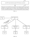
- FIG. 1A is a flowchart illustrating a method according to the present disclosure.
- the flow may be applied to a first VTEP device.
- the first VTEP device is just named for being distinguished from a VTEP device to be mentioned below and not intended to define a particular VTEP device.
- the first VTEP device may be a main VTEP device applied in a backbone network, or a VTEP device playing a role of manager in an EVPN.
- FIG. 1A With reference to FIG. 1B , the method illustrated in FIG. 1A will be described by taking a main VTEP device 110 as a first VTEP device and a first branch VTEP device 121 as a second VTEP device for example, where the main VTEP device 110 may be connected with a server 130, and all branch VTEP devices 121, 122, 123 may be connected with hosts 141, 142, 143.
- the flow may include the following blocks.
- the first VTEP device 110 may receive an EVPN route from the second VTEP device 121.
- the second VTEP device is just named for being distinguished from the first VTEP device and a VTEP device to be mentioned below and not intended to define a particular VTEP device.
- the first VTEP device may be a main VTEP device applied in a backbone network
- the second VTEP device may be a branch VTEP device applied in a branch.
- the first VTEP device may be a VTEP device playing a role of manager in an EVPN
- the second VTEP device may be a VTEP device playing a non-manager role.
- the second VTEP device may learn an ARP entry corresponding to the host according to the ARP request and generate a corresponding EVPN route.
- the EVPN route generated by the second VTEP device may be an EVPN class-2 route.
- the EVPN class-2 route may refer to a route (MAC/IP advertisement route) for advertising reachability of Media Access Control (MAC)/Internet Protocol (IP).
- the EVPN route generated by the second VTEP device in the present disclosure may carry a role attribute of the second VTEP device.
- the role attribute of the second VTEP device may be preconfigured in the second VTEP device according to a service requirement, and may also be dynamically determined by negotiation with another VTEP device specified in a network, for example, the first VTEP device, which will not be specifically limited in the present disclosure.
- the EVPN route received by the first VTEP device 110 from the second VTEP device 121 at block 101 carries the role attribute of the second VTEP device 121.
- the role attribute of the second VTEP device 121 may have a specified first role attribute value.
- the role attribute of the second VTEP device 121 has the first role attribute value, it means that the distribution of the EVPN route from the second VTEP device 121 needs to be controlled, which can be seen in block 102.
- the first VTEP device 110 may check whether the received EVPN route carries the role attribute. When determining that the received EVPN route carries the role attribute and the carried role attribute has a specified first role attribute value, the first VTEP device 110 controls the distribution of the EVPN route according to a set route synchronization control strategy.
- a precondition for the first VTEP device 110 to control the distribution of the EVPN route based on the set route synchronization control strategy is that the role attribute carried by the EVPN route has the first role attribute value. That is, the first VTEP device 110 can control the distribution of the EVPN route according to the set route synchronization control strategy as long as the role attribute carried by the EVPN route is the first role attribute value.
- the main VTEP device 110 synchronizes an EVPN route received from a branch VTEP device 121 to other branch VTEP devices 122, 123 without any control, it may lead to intercommunication between different branches, and that further makes it impossible to prohibit different branches from accessing one another as required.
- the flow shown in FIG. 1A in the present disclosure may be applied, and an EVPN route sent by a branch VTEP device is added with a role attribute so as to ensure that the main VTEP device can control the distribution of the EVPN route.
- the main VTEP device synchronizes an EVPN route received from a branch VTEP device to all other branch VTEP devices without any control, thereby effectively improving confidentiality and security of services.
- the branch VTEP devices 121, 122, 123 may recognize which VTEP device is the main VTEP device 110 first so as to send EVPN routes to the main VTEP device 110, and each of the EVPN routes sent to the main VTEP device 110 carries a role attribute (which specifically has a first role attribute value for representing a branch role).
- the main VTEP device 110 can control the distribution of an EVPN route based on the role attribute carried by the EVPN route only after receiving the EVPN route distributed by each of the branch VTEP devices 121, 122, 123.
- each of the branch VTEP devices 121, 122, 123 may initiatively send an inquiry packet in a network after being powered up and then recognize the main VTEP device 110 based on a reply from the main VTEP device 110 to the inquiry packet.
- the main VTEP device 110 may periodically send a packet to notify the main VTEP device 110 to each of the branch VTEP devices 121, 122, 123. This will not be specifically defined herein.
- the route synchronization control strategy in block 102 is mainly to appropriately prohibit distributing of some EVPN routes, which are not required to be distributed to other VTEP devices. For example, only some EVPN routes required to be distributed to other VTEP devices may be distributed according to service requirements.
- controlling the distribution of an EVPN route according to a set route synchronization control strategy may be specifically achieved in a plurality of manners.
- the three manners therein are shown as follows.
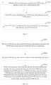
- the first VTEP device controls the distribution of the EVPN route according to the set route synchronization control strategy at block 102, which may specifically include the following blocks.
- the first host information may specifically include host address information.
- the route synchronization rule may be preset based on a service requirement and may contain host information such as host address information and a route distribution identifier.
- the route distribution identifier is used to indicate that an EVPN route carrying the host address information is allowed to be distributed.
- checking whether the first host information carried by the EVPN route matches the local route synchronization rule may include: with the first host information carried by the EVPN route as a keyword, checking whether a route synchronization rule containing the keyword is present in a local route synchronization rule table; if yes, determining that the first host information carried by the EVPN route matches the local route synchronization rule; otherwise, determining that the first host information carried by the EVPN route does not match the local route synchronization rule.
- the EVPN route is distributed to VTEP devices other than the second VTEP device.
- the EVPN route is prohibited from being distributed to VTEP devices other than the second VTEP device.
- the main VTEP device 110 may control the distribution of the EVPN route from the branch VTEP device 121 according to the route synchronization rule rather than distributing the EVPN route received from the branch VTEP device 121 to other branch VTEP devices 122, 123 without control. In this way, service confidentiality, service security and the like between branches can be maintained.
- the route synchronization rule may not be set on the first VTEP device 110 but on a server 130 to which the first VTEP device is connected.
- FIG. 3B illustrates an application network of the manner 1_2 with the main VTEP device 110 as the first VTEP device, the branch VTEP device 121 as the second VTEP device, and the route synchronization rule being stored in the server 130.
- the first VTEP device controls the distribution of the EVPN route according to the set route synchronization control strategy at block 102, which may specifically include the following blocks.
- the first VTEP device 110 sends the first host information carried by the EVPN route to the server 130 to which the device 110 is connected so as to trigger the server 130 to query whether the first host information matches the set route synchronization rule.
- a route synchronization rule may be preset in the above server 130 based on a service requirement and the set route synchronization rule may contain host information such as a host IP address and a route distribution identifier.
- the route distribution identifier is used to indicate the EVPN route carrying the host information is allowed to be distributed.
- the first VTEP device 110 receives a query result returned by the server.
- the first VTEP device 110 distributes the EVPN route to other VTEP devices 122, 123; and if the query result indicates that the first host information does not match the route synchronization rule, the first VTEP device 110 prohibits distributing the EVPN route to other VTEP devices 122, 123.
- the main VTEP device 110 queries the server 130 to control the distribution of the EVPN route from the branch VTEP device 121 according to the route synchronization rule rather than distributing the EVPN route received from the branch VTEP device 121 to other branch VTEP devices 122, 123 without control. In this way, service confidentiality, service security and the like between branches can be maintained.
- the route synchronization rule may be further detailed, and the route synchronization rule may further include an identifier of a network to which the EVPN route is to be distributed, such as an identifier of a branch network, and the like.
- the first VTEP device may distribute the EVPN route to VTEP devices other than the second VTEP device, which may specifically include: determining a network identifier in the route synchronization rule matching the first host information; and distributing the EVPN route to a VTEP device in a network corresponding to the network identifier.
- the first VTEP device controls, as required, the EVPN route to be distributed to which VTEP devices of which networks.
- distributing the EVPN route to the VTEP device in the network corresponding to the network identifier may specifically include: deleting the first role attribute value carried in the EVPN route and distributing the EVPN route with the first role attribute value being deleted to the VTEP device in the network corresponding to the network identifier.
- distributing the EVPN route to the VTEP device in the network corresponding to the network identifier may specifically include: replacing the first role attribute value carried in the EVPN route with a second role attribute value and distributing the EVPN route obtained by the replacement to the VTEP device in the network corresponding to the network identifier.
- the manner 1_3 is simpler and the EVPN route may be directly prohibited from being distributed to VTEP devices other than the second VTEP device.
- the first VTEP device may control the distribution of the EVPN route according to the set route synchronization control strategy at block 102, which may specifically include: prohibiting distributing the EVPN route to VTEP devices other than the second VTEP device.
- the first VTEP device 110 may directly prohibit distributing the EVPN route to other VTEP devices 122, 123 so as to ensure security and confidentiality of network.
- the first VTEP device 110 may subsequently distribute the EVPN route as required based on a route request, which may be detailed in the following description.
- the first VTEP device 110 prohibits the EVPN route sent by the second VTEP device 121 from being distributed to other VTEP devices 122, 123, subsequently, there may be a service requirement that the host (hereinafter referred to as a second host 142) to which the third VTEP device 122 is connected accesses the host (hereinafter referred to as a first host 141) to which the second VTEP device 121 is connected.
- the third VTEP device 122 and the second VTEP device 121 may reside on different networks such as different branch networks.
- the second VTEP device 121 may be a VTEP device in a first network
- the third VTEP device 122 may be a VTEP device in a second network.
- the present disclosure provides the following two manners in which the second host accesses the first host.
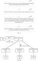
- achieving accessing of the second host 142 to the first host 141 may include the following blocks.
- the first VTEP device 110 may receive a query request message carrying the first host information from the third VTEP device 122.
- the query request message is sent because the third VTEP device 122 has no EVPN route corresponding to the first host 141 when the second host 142 connected with the third VTEP device 122 intends to access the first host 141.
- the third VTEP device 122 to which the second host 142 is connected may send the query request message to the first VTEP device 110.
- the query request message may carry the first host information such as a host IP address.
- the first host information may be obtained by the third VTEP device 122 from a Domain Name System (DNS) server before the query request message is sent.
- DNS Domain Name System
- the first VTEP device 110 may distribute the received EVPN route carrying the first host information to the third VTEP device.
- distributing the received EVPN route carrying the first host information to the third VTEP device as described above may include: deleting the first role attribute value carried in the received EVPN route carrying the first host information and distributing the EVPN route with the first role attribute value being deleted therefrom to the third VTEP device.
- the distributing the received EVPN route carrying the first host information to the third VTEP device as described above may include: modifying the first role attribute value carried in the received EVPN route carrying the first host information to a second role attribute value and distributing the EVPN route with the modified role attribute value to the third VTEP device.
- the role attribute carried by the EVPN route is the second role attribute value, it is indicated that the distribution of the EVPN route does not need to be controlled. Therefore, it is realized that the first VTEP device distributes EVPN routes according to a uniform principle.
- the third VTEP device 122 may establish a VXLAN tunnel with the first VTEP device 110, and may generate a forwarding entry according to the received EVPN route and then distribute the forwarding entry to a local forwarding table, so as to guide packet forwarding for the second host 142 to access the first host 141 subsequently.
- the second host 142 accesses the first host 141.
- the manner 2_2 may require that after receiving an EVPN route from any VTEP device, the first VTEP device registers the host information carried in the received EVPN route on a server to which the first VTEP device is connected.
- the first VTEP device receives the EVPN route from the second VTEP device at block 101 as described above, which may further include: registering the first host information carried by the EVPN route on a server to which the first VTEP device is connected.
- FIG. 5B illustrates an application network of the manner 2_2 with the main VTEP device 110 as the first VTEP device, a branch VTEP device 121 as the second VTEP device and a branch VTEP device 122 as the third VTEP device.
- achieving accessing of the second host to the first host may include the following blocks.
- the first VTEP device 110 may receive a query request message carrying the first host information from the third VTEP device 122, where the query request message is sent because the third VTEP device 122 has no EVPN route corresponding to the first host 141 when the second host 142 connected with the third VTEP device 122 accesses the first host 141.
- the first VTEP device 110 may send the query request message to the server 130 to trigger the server 130 to query the first host information in the registered host information.
- the first VTEP device 110 may receive a response message returned by the server 130, where the response message is sent when the server 130 obtains the first host information and the first host information matches the set route synchronization rule.
- the manner 2_2 may save of resources of the main VTEP device 110 greatly.
- the first VTEP device 110 may distribute the received EVPN route carrying the first host information to the third VTEP device 122.
- distributing the received EVPN route carrying the first host information to the third VTEP device as described above may include: deleting the first role attribute value carried in the received EVPN route carrying the first host information and distributing the EVPN route with the first role attribute value being deleted to the third VTEP device.
- the distributing the received EVPN route carrying the first host information to the third VTEP device as described above may include: modifying the first role attribute value carried in the received EVPN route carrying the first host information to a second role attribute value and distributing the EVPN route with the modified role attribute value to the third VTEP device.
- the role attribute carried by the EVPN route is the second role attribute value, it is indicated that the distribution of the EVPN route does not need to be controlled. Therefore, it is realized that the first VTEP device distributes EVPN routes according to a uniform principle.
- the third VTEP device 122 may establish a VXLAN tunnel with the first VTEP device 110, and may generate a forwarding entry according to the received EVPN route and then distribute the forwarding entry to a local forwarding table for guiding packet forwarding for the second host 142 to access the first host 141 subsequently.
- the second host 142 accesses the first host 141.
- the reply packet may be a refresh packet in the EVPN.
- FIG. 6 is a diagram illustrating an application network according to an example of the present disclosure.
- a main VTEP device 610 may be connected with a server 640; a branch VTEP device 621 in a first branch may be connected with a first host 631; a branch VTEP device 622 in a second branch may be connected with a second host 632; and a branch VTEP device 623 in a third branch may be connected with a third host 633.
- the first branch is taken for example herein, and the principles of the second branch and the third branch are similar to that of the first branch.
- the first host 631 in the first branch may send an ARP request.
- a source IP address of the ARP request is the IP address (10.10.2.1/32) of the first host 631.
- the branch VTEP device 621 may receive the ARP request and learn an ARP entry corresponding to the host 631 based on the APR request.
- the ARP entry may include the IP address (10.10.2.1/32) and an egress port of the first host 631, the egress port being a port via which the branch VTEP device 621 is connected with the host 631.
- the branch VTEP device 621 may generate an EVPN route (e.g., an EVPN class-2 route, denoted as EVPN class-2 route 1_1) corresponding to the IP address of the host 631, where the EVPN class-2 route 1_1 includes the host information of the host 631 (e.g., the IP address 10.10.2.1/32 of the host 631).
- an EVPN route e.g., an EVPN class-2 route, denoted as EVPN class-2 route 1_1
- the host information of the host 631 e.g., the IP address 10.10.2.1/32 of the host 631.
- the branch VTEP device 621 may add a first role attribute value (e.g., 1) for representing a branch role into the generated EVPN class-2 route 1_1.
- a first role attribute value e.g., 1
- the branch VTEP device 621 may send the EVPN class-2 route 1_1 to the main VTEP device 610. Next hop of the EVPN class-2 route 1_1 is the branch VTEP device 621.
- the main VTEP device 610 may determine the role attribute carried by the received EVPN class-2 route 1_1 is the first role attribute value (e.g., 1) for representing the branch role. Then the received EVPN class-2 route 1_1 may be prohibited being distributed to the branch VTEP device 622 and the branch VTEP device 623 as shown in the above manner 1_3. Thus, the host 632 (IP address 10.10.3.1/32) in the second branch and the host 633 (IP address 10.10.4.1/32) in the third branch cannot access the host 631 (IP address 10.10.2.1/32) in the first branch.
- IP address 10.10.3.1/32 IP address 10.10.3.1/32
- IP address 10.10.4.1/32 in the third branch cannot access the host 631 (IP address 10.10.2.1/32) in the first branch.
- the main VTEP device 610 may control the distribution of the EVPN class-2 route 1_1 in the above manner 1_3, and the principle of the manner 1_3 is similar to those of the above manner 1_1 and the manner 1_2, which will not be described redundantly.
- any two branches may be desired to communicate with each other as required, for example, it is assumed that communication of the third branch and the first branch are desired, i.e., the host 633 (IP address 10.10.4.1/32) in the third branch intends to access the host 631 (IP address 10.10.2.1/32) in the first branch.
- the above main VTEP device 610 may further register the IP address 10.10.2.1/32 of the host 631 in the EVPN class-2 route on the server 640 connected to the main VTEP device 610.
- the main VTEP device 610 may realize the communication of the third branch and the first branch by using the above manner 2_2, which is similar to the above manner 2_1 in principal and will not be described redundantly.
- the branch VTEP device 623 may send a query request message the main VTEP device 610, where the query request message carries the IP address 10.10.2.1/32 of the host 631.
- the main VTEP device 610 may receive the query request message and forward the message to the server 640 connected to the main VTEP device 610.
- the server 640 may receive the query request message and search for the IP address of the host 631 in all host IP addresses registered on the server 640.
- the server 640 may send a response message to the main VTEP device 610.
- the route synchronization rule may contain the IP address of the host 631, and an identifier allowing an EVPN class-2 route (i.e., the above EVPN class 2 route 1_1) corresponding to the IP address of the host 631 to be distributed to the branch VTEP device 623.
- the main VTEP device 610 may receive the response message and forward the received response message to the branch VTEP device 623.
- the branch VTEP device 623 may send an extended refresh packet to the main VTEP device 610, where the refresh packet carries the IP address of the host 631.
- the main VTEP device 610 may modify the role attribute of the EVPN class-2 route (i.e., the above EVPN class 2 route 1_1) corresponding to the IP address of the host 631 carried by the refresh packet from the first role attribute value (e.g., 1) to the second role attribute value (e.g., 0) representing the main VTEP device and then send the route to the branch VTEP device 623.
- the EVPN class-2 route 1_1 with the modified role attribute is denoted as EVPN class-2 route 1_2.
- the branch VTEP device 623 may generate a VXLAN tunnel from the branch VTEP device 623 to the main VTEP device 610 after receiving the EVPN class-2 route 1_2, and generate a forwarding entry according to the EVPN class-2 route 1_2 and distribute the forwarding entry to a local forwarding table to guide packet forwarding for the host 633 in the third branch to access the host 631 in the first branch.
- the branch VTEP device 621 may send a query request message to the main VTEP device 610, where the query request message carries the IP address 10.10.4.1/32 of the host 633.
- the main VTEP device 610 may receive the query request message and forward the query request message to the server 640 connected to the main VTEP device 610.
- the server 640 may receive the query request message and search for the IP address of the host 633 in all host IP addresses registered on the server 640.
- the server 640 may send a response message to the main VTEP device 610.
- the route synchronization rule contains the IP address of the host 633, and an identifier allowing an EVPN class-2 route (denoted as the above EVPN class 2 route 1_3) corresponding to the IP address of the host 633 to be distributed to the branch VTEP device 621.
- the main VTEP device 610 may receive the response message and forward the received response message to the branch VTEP device 621.
- the branch VTEP device 621 may send an extended refresh packet to the main VTEP device 610, where the refresh packet carries the IP address of the host 633.
- the main VTEP device 610 may modify the role attribute of the EVPN class-2 route (i.e., the above EVPN class 2 route 1_3) corresponding to the IP address of the host 633 carried by the refresh packet from the first role attribute value (e.g., 1) to the second role attribute value (e.g., 0) representing the main VTEP device and then send the route to the branch VTEP device 621.
- the EVPN class-2 route 1_3 with the modified role attribute is denoted as EVPN class-2 route 1_4.
- the branch VTEP device 621 may generate a VXLAN tunnel from the branch VTEP device 621 to the main VTEP device 610 after receiving the EVPN class-2 route 1_4, and generate a forwarding entry according to the EVPN class-2 route 1_4 and distribute the forwarding entry to a local forwarding table to guide packet forwarding for the host 631 to access the host 633.
- communication of the first branch and the third branch is realized.
- an EVPN class-2 route which is originally sent by the branch VTEP device 621 to the main VTEP device 610 and distributed to other branch VTEP devices 622, 623, may be synchronized only to the main VTEP device 610 rather than to the branch VTEP devices 622, 623 due to the control of the main VTEP device 610.
- a permission of the main VTEP device 610 is required.
- the different branches can communicate with each other only when they have the permission of the main VTEP device 610.
- the security and confidentiality of an enterprise network can be guaranteed.
- the main VTEP device may negotiate with each branch VTEP device over role attribute recognition capability; meanwhile, the main VTEP device may advertise the role attribute (the second role attribute value for presenting the main VTEP device) of the main VTEP device to each branch VTEP device; each branch VTEP device may advertise the role attribute thereof (the first role attribute value for representing the branch role) to the main VTEP device; and the main VTEP device may record the role attributes of each branch VTEP device.
- FIG. 7 is a schematic diagram illustrating a structure of a device according to an example of the present disclosure.
- the device may be applied to a main VTEP device on a backbone network as shown in FIG. 1B , FIG. 3B , FIG. 5B and FIG. 6 and include:
- the controlling unit 703 controls the distribution of the EVPN route according to the set route synchronization control strategy, which specifically includes: sending first host information carried by the EVPN route to a server connected to the device to trigger the server to query whether the first host information matches a set route synchronization rule; receiving a query result returned by the server; distributing the EVPN route to a VTEP device other than the second VTEP device if the query result is a first query result identifier representing that the first host information matches the route synchronization rule; and prohibiting distributing the EVPN route to a VTEP device other than the second VTEP device if the query result is a second query result identifier representing that the first host information does not match the route synchronization rule.
- the controlling unit 703 controls the distribution of the EVPN route according to the set route synchronization control strategy, which specifically includes: checking whether the first host information carried by the EVPN route matches a local route synchronization rule; if yes, distributing the EVPN route to a VTEP device other than the second VTEP device; and if no, prohibiting distributing the EVPN route to a VTEP device other than the second VTEP device.
- the controlling unit 703 may distribute the EVPN route to a VTEP device other than the second VTEP device, which may specifically include: determining a network identifier in the route synchronization rule matching the first host information; and distributing the EVPN route to a VTEP device in a network corresponding to the network identifier.
- the controlling unit 703 may control the distribution of the EVPN route according to the set route synchronization control strategy, which may specifically include: prohibiting distributing the EVPN route to a VTEP device other than the second VTEP device.
- the receiving unit 701 may receive the EVPN route from the second VTEP device, which may further include: registering the first host information carried by the EVPN route on the server connected to the device.
- the receiving unit 701 may further receive a query request message from a third VTEP device, where the query request message is sent because a second host connected to the third VTEP device accesses a first host when the EVPN route is not locally present in the third VTEP device; and the first host is a host corresponding to the first host information carried by the EVPN route, and the query request message carries the first host information.
- the controlling unit 703 may further send the query request message to the server to trigger the server to query the first host information carried by the query request message in registered host information.
- the receiving unit 701 may further receive a response message returned by the server, where the response message is sent when the server obtains the first host information and the first host information matches the set route synchronization rule.
- the controlling unit 703 may further distribute the received EVPN route carrying the first host information to the third VTEP device.
- the receiving unit 701 may further receive the query request message from the third VTEP device, where the query request message is sent because the second host connected to the third VTEP device accesses the first host when the EVPN route is not locally present in the third VTEP device; the first host is a host corresponding to the first host information carried by the EVPN route; and the query request message carries the first host information.
- the controlling unit 703 may further distribute the received EVPN route carrying the first host information to the third VTEP device when determining that the first host information carried by the query request message is present in local host information and that a route synchronization rule matching the first host information is locally present.
- the controlling unit 703 before the controlling unit 703 distributes the received EVPN route carrying the first host information to the third VTEP device, the following may be further included: sending a response message to the third VTEP device; receiving a reply packet sent by the third VTEP device based on the response message, where the reply packet carries the first host information; and obtaining the first host information from the received reply packet, and then continuing to distribute the received EVPN route carrying the first host information to the third VTEP device.
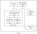
- FIG. 8 is a schematic diagram illustrating a hardware structure according to the present disclosure.
- the device may include:
- the hardware structure may also include a power supply component 803 configured to execute power management for the device, a wired or wireless network interface 804 configured to connect the device to a network, and an input/output (I/O) interface 805.
- a power supply component 803 configured to execute power management for the device
- a wired or wireless network interface 804 configured to connect the device to a network
Landscapes
- Engineering & Computer Science (AREA)
- Computer Networks & Wireless Communication (AREA)
- Signal Processing (AREA)
- Computer Security & Cryptography (AREA)
- Computer Hardware Design (AREA)
- Computing Systems (AREA)
- General Engineering & Computer Science (AREA)
- Data Exchanges In Wide-Area Networks (AREA)
Claims (11)
- Verfahren zum Steuern einer EVPN-Route (Ethernet Virtual Private Networks route),
dadurch gekennzeichnet, dass es umfasst:Empfangen (101) mittels einer ersten VTEP-Vorrichtung (Virtual eXtensible Local Area Network Tunnel End Point device) (110) einer EVPN-Route von einer zweiten VTEP-Vorrichtung (121);Prüfen ob die EVPN-Route ein Rollen-Attribut überträgt, mittels der ersten VTEP-Vorrichtung, wobei das Rollen-Attribut einen ersten Rollen-Attribut-Wert hat, der anzeigt, dass die EVPN-Route von einer Zweig-VTEP-Vorrichtung kommt, und wobei die zweite VTEP-Vorrichtung die Zweig-VTEP-Vorrichtung ist;Steuern (102) von Verteilung der EVPN-Route mittels der ersten VTEP-Vorrichtung entsprechend einer festgelegten Steuerungsstrategie für Routensynchronisation, wenn festgestellt wird, dass die EVPN-Route das Rollen-Attribut überträgt und das übertragene Rollen-Attribut den ersten Rollen-Attribut-Wert hat;wobei Steuern (102) der Verteilung der EVPN-Route gemäß der Steuerungsstrategie für Routensynchronisation umfasst:Senden (102b1) über die EVPN-Route übertragener erster Host-Informationen zu einem mit der ersten VTEP-Vorrichtung verbundenen Server (130) mittels der ersten VTEP-Vorrichtung (110), um den Server zu veranlassen, abzufragen, ob die ersten Host-Informationen mit einer festgelegten Regel für Routensynchronisation übereinstimmen,Empfangen (102b2) eines von dem Server zurückgeführten Abfrage-Ergebnisses mittels der ersten VTEP-Vorrichtung,Verteilen (102b3) der EVPN-Route an eine andere VTEP-Vorrichtung als die zweite VTEP-Vorrichtung (121) mittels der ersten VTEP-Vorrichtung, wenn das Abfrage-Ergebnis anzeigt, dass die ersten Host-Informationen mit einer festgelegten Regel für Routensynchronisation übereinstimmen, undUnterbinden (102b3) des Verteilens der EVPN-Route an eine andere VTEP-Vorrichtung als die zweite VTEP-Vorrichtung mittels der ersten VTEP-Vorrichtung, wenn das Abfrage-Ergebnis anzeigt, dass die ersten Host-Informationen nicht mit der Regel für Routensynchronisation übereinstimmen; oderwobei Steuern (102) der Verteilung der EVPN-Route gemäß der Steuerungsstrategie für Routensynchronisation umfasst:Prüfen (102a1), ob über die EVPN-Route übertragene erste Host-Informationen mit einer lokal in der ersten VTEP-Vorrichtung gespeicherten Regel für Routensynchronisation übereinstimmen, mittels der ersten VTEP-Vorrichtung (110),Verteilen (102a2) der EVPN-Route an eine andere VTEP-Vorrichtung als die zweite VTEP-Vorrichtung (121) mittels der ersten VTEP-Vorrichtung, wenn die ersten Host-Informationen mit der Regel für Routensynchronisation übereinstimmen, undUnterbinden (102a3) des Verteilens der EVPN-Route an eine andere VTEP-Vorrichtung als die zweite VTEP-Vorrichtung mittels der ersten VTEP-Vorrichtung, wenn die ersten Host-Informationen nicht mit der Regel für Routensynchronisation übereinstimmen. - Verfahren nach Anspruch 1, wobei Verteilen der EVPN-Route an die andere VTEP-Vorrichtung als die zweite VTEP-Vorrichtung (121) umfasst:Bestimmen einer Netzwerkkennung in der Regel für Routensynchronisation, die mit den über die EVPN-Route übertragenen ersten Host-Informationen übereinstimmt, mittels der ersten VTEP-Vorrichtung (110); undVerteilen der EVPN-Route an eine VTEP-Vorrichtung in einem der Netzwerkkennung entsprechenden Netz, mittels der ersten VTEP-Vorrichtung.
- Verfahren nach Anspruch 1, wobei Steuern (102) der Verteilung der EVPN-Route entsprechend der Steuerungsstrategie für Routensynchronisation umfasst:
Unterbinden des Verteilens der EVPN-Route an eine andere VTEP-Vorrichtung als die zweite VTEP-Vorrichtung (121) mittels der ersten VTEP-Vorrichtung (110). - Verfahren nach Anspruch 1, wobei es des Weiteren umfasst:Registrieren über die empfangene EVPN-Route übertragener erster Host-Informationen an einem mit der ersten VTEP-Vorrichtung verbundenen Server (130) mittels der ersten VTEP-Vorrichtung (110);Empfangen (501) einer Abfrageanforderungs-Nachricht von einer dritten VTEP-Vorrichtung (122) mittels der ersten VTEP-Vorrichtung, wobei die Abfrageanforderungs-Nachricht gesendet wird, wenn die EVPN-Route nicht lokal in der dritten VTEP-Vorrichtung vorhanden ist und auf einen ersten Host von einem zweiten Host (142) zugegriffen werden soll; wobei der erste Host ein den ersten Host-Informationen entsprechender Host ist, der zweite Host ein mit der dritten VTEP-Vorrichtung verbundener Host ist; und die Abfrageanforderungs-Nachricht die ersten Host-Informationen überträgt;Senden (502) der Abfrageanforderungs-Nachricht zu dem Server mittels der ersten VTEP-Vorrichtung; undVerteilen (504) der EVPN-Route an die dritte VTEP-Vorrichtung entsprechend einer von dem Server zurückgeführten Antwort-Nachricht mittels der ersten VTEP-Vorrichtung, wobei die Antwort-Nachricht gesendet wird, wenn der Server in Reaktion auf die Abfrageanforderungs-Nachricht die ersten Host-Informationen anhand lokal registrierter Host-Informationen ermittelt und die ersten Host-Informationen mit der festgelegten Regel für Routensynchronisation übereinstimmen.
- Verfahren nach Anspruch 1, wobei es des Weiteren umfasst:Empfangen (401) einer Abfrageanforderungs-Nachricht von einer dritten VTEP-Vorrichtung (122) mittels der ersten VTEP-Vorrichtung (110), wobei die Abfrageanforderungs-Nachricht gesendet wird, wenn die EVPN-Route nicht lokal in der dritten VTEP-Vorrichtung vorhanden ist und auf einen ersten Host von einem zweiten Host (142) zugegriffen werden soll; wobei der erste Host ein den über die EVPN-Route übertragenen ersten Host-Informationen entsprechender Host ist, der zweite Host ein mit der dritten VTEP-Vorrichtung verbundener Host ist; und die Abfrageanforderungs-Nachricht die ersten Host-Informationen überträgt; sowieVerteilen (402) der EVPN-Route an die dritte VTEP-Vorrichtung mittels der ersten VTEP-Vorrichtung, wenn festgestellt wird, dass die ersten Host-Informationen in lokalen Host-Informationen vorhanden sind und dass eine mit den ersten Host-Informationen übereinstimmende Regel für Routensynchronisation lokal vorhanden ist.
- Verfahren nach Anspruch 4 oder 5, wobei es des Weiteren umfasst:Senden einer Antwort-Nachricht mittels der ersten VTEP-Vorrichtung (110) zu der dritten VTEP-Vorrichtung (122);Empfangen eines von der dritten VTEP-Einrichtung auf Basis der Antwort-Nachricht gesendeten Antwort-Paketes mittels der ersten VTEP-Einrichtung, wobei das Antwort-Paket die ersten Host-Informationen überträgt; undErmitteln der ersten Host-Informationen aus dem empfangenen Antwort-Paket mittels der ersten VTEP-Vorrichtung
- Vorrichtung, die Einrichtungen zum Steuern einer EVPN-Route (Ethernet Virtual Private Networks route) umfasst, wobei die Vorrichtung bei einer VTEP-Vorrichtung (Virtual eXtensible Local Area Network Tunnel End Point device) (110) eingesetzt wird, und dadurch gekennzeichnet, dass sie umfasst:eine Empfangs-Einheit (701), die so konfiguriert ist, dass sie eine EVPN-Route von einer zweiten VTEP-Vorrichtung (102) empfängt (101);eine Prüf-Einheit (702), die so konfiguriert ist, dass sie prüft, ob die EVPN-Route ein Rollen-Attribut überträgt, wobei das Rollen-Attribut einen ersten Rollen-Attribut-Wert hat,der anzeigt, dass die EVPN-Route von einer Zweig-VTEP-Vorrichtung kommt, und wobei die zweite VTEP-Vorrichtung die Zweig-VTEP-Vorrichtung ist;eine Steuerungs-Einheit (703), die so konfiguriert ist, dass sie Verteilung der EVPN-Route entsprechend einer festgelegten Steuerungsstrategie für Routensynchronisation steuert (102), wenn die Prüf-Einheit feststellt, dass die EVPN-Route das Rollen-Attribut überträgt und das übertragene Rollen-Attribut den ersten Rollen-Attribut-Wert hat;wobei die Steuerungs-Einheit (703) konfiguriert ist zum:Senden über die EVPN-Route übertragener erster Host-Informationen zu einem mit der ersten VTEP-Vorrichtung (110) verbundenen Server (130), um den Server zu veranlassen, abzufragen, ob die ersten Host-Informationen mit einer festgelegten Regel für Routensynchronisation übereinstimmen,Empfangen (102b2) eines von dem Server zurückgeführten Abfrage-Ergebnisses, Verteilen (102b3) der EVPN-Route an eine andere VTEP-Vorrichtung als die zweite VTEP-Vorrichtung (121), wenn das Abfrage-Ergebnis anzeigt, dass die ersten Host-Informationen einer festgelegten Regel für Routensynchronisation entsprechen, undUnterbinden (102b3) des Verteilens der EVPN-Route an eine andere VTEP-Vorrichtung als die zweite VTEP-Vorrichtung, wenn das Abfrage-Ergebnis anzeigt, dass die ersten Host-Informationen nicht mit der Regel für Routensynchronisation übereinstimmen; oderwobei die Steuerungs-Einheit (703) konfiguriert ist zum:Prüfen (102a1), ob über die EVPN-Route übertragene erste Host-Informationen mit einer lokal in der ersten VTEP-Vorrichtung (110) gespeicherten Regel für Routensynchronisation übereinstimmen,Verteilen (102a2) der EVPN-Route an eine andere VTEP-Vorrichtung als die zweite VTEP-Vorrichtung (121), wenn die ersten Host-Informationen mit der Regel für Routensynchronisation übereinstimmen, undUnterbinden (102a3) des Verteilens der EVPN-Route an eine andere VTEP-Vorrichtung als die zweite VTEP-Vorrichtung, wenn die ersten Host-Informationen nicht mit der Regel für Routensynchronisation übereinstimmen.
- Vorrichtung nach Anspruch 7, wobei die Steuerungs-Einheit (703) konfiguriert ist zum:Bestimmen einer Netzwerkkennung in der Regel für Routensynchronisation, die mit den über die EVPN-Route übertragenen ersten Host-Informationen übereinstimmt; undVerteilen der EVPN-Route an eine VTEP-Vorrichtung in einem der Netzwerkkennung entsprechenden Netz.
- Vorrichtung nach Anspruch 7, wobei die Steuerungs-Einheit (703) konfiguriert ist zum:
Unterbinden des Verteilens der EVPN-Route an eine andere VTEP-Vorrichtung als die zweite VTEP-Vorrichtung (121). - Vorrichtung nach Anspruch 7, wobei:die Empfangs-Einheit (701) des Weiteren konfiguriert ist zum:Registrieren über die EVPN-Route übertragener erster Host-Informationen an einem mit der ersten VTEP-Vorrichtung (110) verbundenen Server (130) ; undEmpfangen (501) einer Abfrageanforderungs-Nachricht von einer dritten VTEP-Vorrichtung (122), wobei die Abfrageanforderungs-Nachricht gesendet wird, wenn die EVPN-Route nicht lokal in der dritten VTEP-Vorrichtung vorhanden ist und auf einen ersten Host von einem zweiten Host (142) zugegriffen werden soll; wobei der erste Host ein den ersten Host-Informationen entsprechender Host ist, der zweite Host ein mit der dritten VTEP-Vorrichtung verbundener Host ist; und die Abfrageanforderungs-Nachricht die ersten Host-Informationen überträgt; unddie Steuerungs-Einheit (703) des Weiteren konfiguriert ist zum:
Senden (502) der Abfrageanforderungs-Nachricht zu dem Server; sowie Verteilen (504) der EVPN-Route an die dritte VTEP-Vorrichtung entsprechend einer durch die Empfangs-Einheit von dem Server empfangenen Antwort-Nachricht, wobei die Antwort-Nachricht gesendet wird, wenn der Server die ersten Host-Informationen anhand lokal registrierter Host-Informationen ermittelt und die ersten Host-Informationen mit der festgelegten Regel für Routensynchronisation übereinstimmen. - Vorrichtung nach Anspruch 7, wobei:die Empfangs-Einheit (701) des Weiteren konfiguriert ist zum:
Empfangen (401) einer Abfrageanforderungs-Nachricht von einer dritten VTEP-Vorrichtung (122), wobei die Abfrageanforderungs-Nachricht gesendet wird, wenn die EVPN-Route nicht lokal in der dritten VTEP-Vorrichtung vorhanden ist und auf einen ersten Host von einem zweiten Host (142) zugegriffen werden soll; wobei der erste Host ein den über die EVPN-Route übertragenen ersten Host-Informationen entsprechender Host ist, der zweite Host ein mit der dritten VTEP-Vorrichtung verbundener Host ist; und die Abfrageanforderungs-Nachricht die ersten Host-Informationen überträgt; unddie Steuerungs-Einheit (703) des Weiteren konfiguriert ist zum:
Verteilen (402) der EVPN-Route an die dritte VTEP-Vorrichtung, wenn in Reaktion auf die Abfrageanforderungs-Nachricht festgestellt wird, dass die ersten Host-Informationen in lokalen Host-Informationen vorhanden sind, und festgestellt wird, dass eine mit den ersten Host-Informationen übereinstimmende Regel für Routensynchronisation lokal vorhanden ist.
Applications Claiming Priority (2)
| Application Number | Priority Date | Filing Date | Title |
|---|---|---|---|
| CN201710277219.XA CN108259356B (zh) | 2017-04-25 | 2017-04-25 | 路由控制方法和装置 |
| PCT/CN2018/083003 WO2018196633A1 (zh) | 2017-04-25 | 2018-04-13 | 路由控制 |
Publications (3)
| Publication Number | Publication Date |
|---|---|
| EP3598705A1 EP3598705A1 (de) | 2020-01-22 |
| EP3598705A4 EP3598705A4 (de) | 2020-04-01 |
| EP3598705B1 true EP3598705B1 (de) | 2023-07-05 |
Family
ID=62721771
Family Applications (1)
| Application Number | Title | Priority Date | Filing Date |
|---|---|---|---|
| EP18790554.2A Active EP3598705B1 (de) | 2017-04-25 | 2018-04-13 | Routingsteuerung |
Country Status (5)
| Country | Link |
|---|---|
| US (1) | US11451466B2 (de) |
| EP (1) | EP3598705B1 (de) |
| JP (1) | JP6963029B2 (de) |
| CN (1) | CN108259356B (de) |
| WO (1) | WO2018196633A1 (de) |
Families Citing this family (7)
| Publication number | Priority date | Publication date | Assignee | Title |
|---|---|---|---|---|
| US11252192B1 (en) * | 2018-09-28 | 2022-02-15 | Palo Alto Networks, Inc. | Dynamic security scaling |
| CN111698151B (zh) * | 2019-03-13 | 2022-06-28 | 华为技术有限公司 | 路由信息管理方法、装置及计算机存储介质 |
| CN113141290B (zh) * | 2020-01-19 | 2023-12-19 | 华为技术有限公司 | 一种报文传输方法、装置及设备 |
| US11398927B1 (en) * | 2021-02-01 | 2022-07-26 | Cisco Technology, Inc. | Systems and methods for subscription based selective EVPN route distribution |
| US11394684B1 (en) * | 2021-05-29 | 2022-07-19 | Dell Products L.P. | Address discovery system |
| CN113542136B (zh) * | 2021-06-07 | 2022-11-18 | 新华三信息安全技术有限公司 | 一种接口属性调整方法及装置 |
| US12452213B2 (en) * | 2022-12-14 | 2025-10-21 | Hewlett Packard Enterprise Development Lp | Update of firewall tables using ethernet virtual private network (EVPN) route type |
Family Cites Families (19)
| Publication number | Priority date | Publication date | Assignee | Title |
|---|---|---|---|---|
| WO2008089303A1 (en) * | 2007-01-17 | 2008-07-24 | Nortel Networks Limited | Border gateway protocol procedures for mpls and layer-2 vpn using ethernet-based tunnels |
| CN101588240A (zh) | 2008-05-20 | 2009-11-25 | 中国人民解放军信息工程大学 | 一种报文处理方法 |
| CN101577875B (zh) * | 2009-06-08 | 2012-05-23 | 中兴通讯股份有限公司 | 路由请求消息前转方法和装置 |
| CN102624623B (zh) * | 2012-03-13 | 2015-07-22 | 杭州华三通信技术有限公司 | 一种vpn路由信息发布方法及设备 |
| CN103095578B (zh) * | 2013-01-29 | 2015-09-30 | 杭州华三通信技术有限公司 | Mpls l3vpn网络中的路由信息控制方法及pe设备 |
| CN103634217B (zh) | 2013-11-13 | 2017-02-08 | 华为技术有限公司 | 路由信息发布的方法、传输报文的方法及装置 |
| CN105099846B (zh) * | 2014-04-30 | 2018-10-19 | 华为技术有限公司 | 传输数据报文的方法和供应商边缘设备 |
| US9794180B2 (en) * | 2014-07-18 | 2017-10-17 | Cisco Technology, Inc. | Reducing transient packet duplication and improving split-horizon filtering |
| CN104270298B (zh) * | 2014-09-30 | 2018-10-09 | 新华三技术有限公司 | 一种vxlan网络中的报文转发方法及装置 |
| CN104283980B (zh) * | 2014-10-09 | 2018-02-09 | 新华三技术有限公司 | 一种地址解析协议代答方法和装置 |
| US9900250B2 (en) * | 2015-03-26 | 2018-02-20 | Cisco Technology, Inc. | Scalable handling of BGP route information in VXLAN with EVPN control plane |
| CN104967620B (zh) * | 2015-06-17 | 2019-01-25 | 中国科学院信息工程研究所 | 一种基于属性访问控制策略的访问控制方法 |
| US10091176B2 (en) * | 2015-09-30 | 2018-10-02 | Juniper Networks, Inc. | Enhanced EVPN MAC route advertisement having MAC (L2) level authentication, security and policy control |
| CN106027396B (zh) * | 2016-04-29 | 2019-09-06 | 新华三技术有限公司 | 一种路由控制方法、装置和系统 |
| US10454877B2 (en) * | 2016-04-29 | 2019-10-22 | Cisco Technology, Inc. | Interoperability between data plane learning endpoints and control plane learning endpoints in overlay networks |
| CN107800602B (zh) * | 2016-08-29 | 2021-01-15 | 华为技术有限公司 | 一种报文处理方法、设备及系统 |
| CN107783815B (zh) * | 2016-08-30 | 2020-12-01 | 华为技术有限公司 | 一种确定虚拟机迁移的方法和装置 |
| US10142129B1 (en) * | 2016-09-27 | 2018-11-27 | Juniper Networks, Inc. | Bum packet filtering in multi-homed EVPN overlay networks |
| CN112929273A (zh) * | 2017-03-14 | 2021-06-08 | 华为技术有限公司 | 一种处理路由的方法、设备及系统 |
-
2017
- 2017-04-25 CN CN201710277219.XA patent/CN108259356B/zh active Active
-
2018
- 2018-04-13 JP JP2019558597A patent/JP6963029B2/ja active Active
- 2018-04-13 US US16/606,730 patent/US11451466B2/en active Active
- 2018-04-13 EP EP18790554.2A patent/EP3598705B1/de active Active
- 2018-04-13 WO PCT/CN2018/083003 patent/WO2018196633A1/zh not_active Ceased
Also Published As
| Publication number | Publication date |
|---|---|
| CN108259356B (zh) | 2020-08-04 |
| CN108259356A (zh) | 2018-07-06 |
| US11451466B2 (en) | 2022-09-20 |
| WO2018196633A1 (zh) | 2018-11-01 |
| JP2020518205A (ja) | 2020-06-18 |
| EP3598705A1 (de) | 2020-01-22 |
| JP6963029B2 (ja) | 2021-11-05 |
| EP3598705A4 (de) | 2020-04-01 |
| US20200136955A1 (en) | 2020-04-30 |
Similar Documents
| Publication | Publication Date | Title |
|---|---|---|
| EP3598705B1 (de) | Routingsteuerung | |
| CN113261248B (zh) | 安全sd-wan端口信息分发 | |
| JP6619894B2 (ja) | アクセス制御 | |
| US12021699B2 (en) | Software defined access fabric without subnet restriction to a virtual network | |
| EP4239973A1 (de) | Paketsendeverfahren, -vorrichtung und -system | |
| WO2019201043A1 (zh) | 网络通信方法、系统、设备及存储介质 | |
| US9961021B2 (en) | Enabling applications in a multi-transport stack environment | |
| US20110032939A1 (en) | Network system, packet forwarding apparatus, and method of forwarding packets | |
| US20140153577A1 (en) | Session-based forwarding | |
| US20140230044A1 (en) | Method and Related Apparatus for Authenticating Access of Virtual Private Cloud | |
| US9319377B2 (en) | Auto-split DNS | |
| CN103441932B (zh) | 一种主机路由表项生成方法及设备 | |
| CN106878288B (zh) | 一种报文转发方法及装置 | |
| US12113770B2 (en) | DHCP snooping with host mobility | |
| CN107094110B (zh) | 一种dhcp报文转发方法及装置 | |
| CN110474802A (zh) | 设备切换方法及装置、服务系统 | |
| CN105591907B (zh) | 一种路由获取方法和装置 | |
| JP6417799B2 (ja) | ネットワークコントローラ、ネットワーク制御方法、およびプログラム | |
| CN108881024B (zh) | 一种组播流量转发方法及装置 | |
| CN107911495A (zh) | 一种mac地址同步方法和vtep | |
| US20260113214A1 (en) | Method and apparatus for performing proxy reply to address request packet, electronic device, and storage medium | |
| JP5350333B2 (ja) | パケット中継装置及びネットワークシステム | |
| US10812370B2 (en) | Unified control plane over MPLS and internet interfaces through BGP | |
| CN106254253B (zh) | 私网路由生成方法以及装置 | |
| US12341772B2 (en) | Management of private networks over multiple local networks |
Legal Events
| Date | Code | Title | Description |
|---|---|---|---|
| STAA | Information on the status of an ep patent application or granted ep patent |
Free format text: STATUS: THE INTERNATIONAL PUBLICATION HAS BEEN MADE |
|
| PUAI | Public reference made under article 153(3) epc to a published international application that has entered the european phase |
Free format text: ORIGINAL CODE: 0009012 |
|
| STAA | Information on the status of an ep patent application or granted ep patent |
Free format text: STATUS: REQUEST FOR EXAMINATION WAS MADE |
|
| 17P | Request for examination filed |
Effective date: 20191018 |
|
| AK | Designated contracting states |
Kind code of ref document: A1 Designated state(s): AL AT BE BG CH CY CZ DE DK EE ES FI FR GB GR HR HU IE IS IT LI LT LU LV MC MK MT NL NO PL PT RO RS SE SI SK SM TR |
|
| AX | Request for extension of the european patent |
Extension state: BA ME |
|
| A4 | Supplementary search report drawn up and despatched |
Effective date: 20200304 |
|
| RIC1 | Information provided on ipc code assigned before grant |
Ipc: H04L 12/911 20130101ALI20200227BHEP Ipc: H04L 12/751 20130101AFI20200227BHEP Ipc: H04L 12/721 20130101ALI20200227BHEP Ipc: H04L 12/715 20130101ALI20200227BHEP |
|
| DAV | Request for validation of the european patent (deleted) | ||
| DAX | Request for extension of the european patent (deleted) | ||
| STAA | Information on the status of an ep patent application or granted ep patent |
Free format text: STATUS: EXAMINATION IS IN PROGRESS |
|
| 17Q | First examination report despatched |
Effective date: 20210610 |
|
| REG | Reference to a national code |
Ref country code: DE Ref legal event code: R079 Free format text: PREVIOUS MAIN CLASS: H04L0012751000 Ipc: H04L0045000000 Ref document number: 602018052891 Country of ref document: DE |
|
| RIC1 | Information provided on ipc code assigned before grant |
Ipc: H04L 47/70 20220101ALI20230124BHEP Ipc: H04L 45/64 20220101ALI20230124BHEP Ipc: H04L 45/02 20220101ALI20230124BHEP Ipc: H04L 45/00 20220101AFI20230124BHEP |
|
| GRAP | Despatch of communication of intention to grant a patent |
Free format text: ORIGINAL CODE: EPIDOSNIGR1 |
|
| STAA | Information on the status of an ep patent application or granted ep patent |
Free format text: STATUS: GRANT OF PATENT IS INTENDED |
|
| INTG | Intention to grant announced |
Effective date: 20230310 |
|
| GRAS | Grant fee paid |
Free format text: ORIGINAL CODE: EPIDOSNIGR3 |
|
| GRAA | (expected) grant |
Free format text: ORIGINAL CODE: 0009210 |
|
| STAA | Information on the status of an ep patent application or granted ep patent |
Free format text: STATUS: THE PATENT HAS BEEN GRANTED |
|
| P01 | Opt-out of the competence of the unified patent court (upc) registered |
Effective date: 20230424 |
|
| AK | Designated contracting states |
Kind code of ref document: B1 Designated state(s): AL AT BE BG CH CY CZ DE DK EE ES FI FR GB GR HR HU IE IS IT LI LT LU LV MC MK MT NL NO PL PT RO RS SE SI SK SM TR |
|
| REG | Reference to a national code |
Ref country code: CH Ref legal event code: EP |
|
| REG | Reference to a national code |
Ref country code: AT Ref legal event code: REF Ref document number: 1585852 Country of ref document: AT Kind code of ref document: T Effective date: 20230715 |
|
| REG | Reference to a national code |
Ref country code: DE Ref legal event code: R096 Ref document number: 602018052891 Country of ref document: DE |
|
| REG | Reference to a national code |
Ref country code: IE Ref legal event code: FG4D |
|
| REG | Reference to a national code |
Ref country code: LT Ref legal event code: MG9D |
|
| REG | Reference to a national code |
Ref country code: NL Ref legal event code: MP Effective date: 20230705 |
|
| REG | Reference to a national code |
Ref country code: AT Ref legal event code: MK05 Ref document number: 1585852 Country of ref document: AT Kind code of ref document: T Effective date: 20230705 |
|
| PG25 | Lapsed in a contracting state [announced via postgrant information from national office to epo] |
Ref country code: NL Free format text: LAPSE BECAUSE OF FAILURE TO SUBMIT A TRANSLATION OF THE DESCRIPTION OR TO PAY THE FEE WITHIN THE PRESCRIBED TIME-LIMIT Effective date: 20230705 |
|
| PG25 | Lapsed in a contracting state [announced via postgrant information from national office to epo] |
Ref country code: GR Free format text: LAPSE BECAUSE OF FAILURE TO SUBMIT A TRANSLATION OF THE DESCRIPTION OR TO PAY THE FEE WITHIN THE PRESCRIBED TIME-LIMIT Effective date: 20231006 |
|
| PG25 | Lapsed in a contracting state [announced via postgrant information from national office to epo] |
Ref country code: ES Free format text: LAPSE BECAUSE OF FAILURE TO SUBMIT A TRANSLATION OF THE DESCRIPTION OR TO PAY THE FEE WITHIN THE PRESCRIBED TIME-LIMIT Effective date: 20230705 |
|
| PG25 | Lapsed in a contracting state [announced via postgrant information from national office to epo] |
Ref country code: IS Free format text: LAPSE BECAUSE OF FAILURE TO SUBMIT A TRANSLATION OF THE DESCRIPTION OR TO PAY THE FEE WITHIN THE PRESCRIBED TIME-LIMIT Effective date: 20231105 |
|
| PG25 | Lapsed in a contracting state [announced via postgrant information from national office to epo] |
Ref country code: SE Free format text: LAPSE BECAUSE OF FAILURE TO SUBMIT A TRANSLATION OF THE DESCRIPTION OR TO PAY THE FEE WITHIN THE PRESCRIBED TIME-LIMIT Effective date: 20230705 Ref country code: RS Free format text: LAPSE BECAUSE OF FAILURE TO SUBMIT A TRANSLATION OF THE DESCRIPTION OR TO PAY THE FEE WITHIN THE PRESCRIBED TIME-LIMIT Effective date: 20230705 Ref country code: PT Free format text: LAPSE BECAUSE OF FAILURE TO SUBMIT A TRANSLATION OF THE DESCRIPTION OR TO PAY THE FEE WITHIN THE PRESCRIBED TIME-LIMIT Effective date: 20231106 Ref country code: NO Free format text: LAPSE BECAUSE OF FAILURE TO SUBMIT A TRANSLATION OF THE DESCRIPTION OR TO PAY THE FEE WITHIN THE PRESCRIBED TIME-LIMIT Effective date: 20231005 Ref country code: LV Free format text: LAPSE BECAUSE OF FAILURE TO SUBMIT A TRANSLATION OF THE DESCRIPTION OR TO PAY THE FEE WITHIN THE PRESCRIBED TIME-LIMIT Effective date: 20230705 Ref country code: LT Free format text: LAPSE BECAUSE OF FAILURE TO SUBMIT A TRANSLATION OF THE DESCRIPTION OR TO PAY THE FEE WITHIN THE PRESCRIBED TIME-LIMIT Effective date: 20230705 Ref country code: IS Free format text: LAPSE BECAUSE OF FAILURE TO SUBMIT A TRANSLATION OF THE DESCRIPTION OR TO PAY THE FEE WITHIN THE PRESCRIBED TIME-LIMIT Effective date: 20231105 Ref country code: HR Free format text: LAPSE BECAUSE OF FAILURE TO SUBMIT A TRANSLATION OF THE DESCRIPTION OR TO PAY THE FEE WITHIN THE PRESCRIBED TIME-LIMIT Effective date: 20230705 Ref country code: GR Free format text: LAPSE BECAUSE OF FAILURE TO SUBMIT A TRANSLATION OF THE DESCRIPTION OR TO PAY THE FEE WITHIN THE PRESCRIBED TIME-LIMIT Effective date: 20231006 Ref country code: FI Free format text: LAPSE BECAUSE OF FAILURE TO SUBMIT A TRANSLATION OF THE DESCRIPTION OR TO PAY THE FEE WITHIN THE PRESCRIBED TIME-LIMIT Effective date: 20230705 Ref country code: ES Free format text: LAPSE BECAUSE OF FAILURE TO SUBMIT A TRANSLATION OF THE DESCRIPTION OR TO PAY THE FEE WITHIN THE PRESCRIBED TIME-LIMIT Effective date: 20230705 Ref country code: AT Free format text: LAPSE BECAUSE OF FAILURE TO SUBMIT A TRANSLATION OF THE DESCRIPTION OR TO PAY THE FEE WITHIN THE PRESCRIBED TIME-LIMIT Effective date: 20230705 |
|
| PG25 | Lapsed in a contracting state [announced via postgrant information from national office to epo] |
Ref country code: PL Free format text: LAPSE BECAUSE OF FAILURE TO SUBMIT A TRANSLATION OF THE DESCRIPTION OR TO PAY THE FEE WITHIN THE PRESCRIBED TIME-LIMIT Effective date: 20230705 |
|
| REG | Reference to a national code |
Ref country code: DE Ref legal event code: R097 Ref document number: 602018052891 Country of ref document: DE |
|
| PG25 | Lapsed in a contracting state [announced via postgrant information from national office to epo] |
Ref country code: SM Free format text: LAPSE BECAUSE OF FAILURE TO SUBMIT A TRANSLATION OF THE DESCRIPTION OR TO PAY THE FEE WITHIN THE PRESCRIBED TIME-LIMIT Effective date: 20230705 Ref country code: RO Free format text: LAPSE BECAUSE OF FAILURE TO SUBMIT A TRANSLATION OF THE DESCRIPTION OR TO PAY THE FEE WITHIN THE PRESCRIBED TIME-LIMIT Effective date: 20230705 Ref country code: EE Free format text: LAPSE BECAUSE OF FAILURE TO SUBMIT A TRANSLATION OF THE DESCRIPTION OR TO PAY THE FEE WITHIN THE PRESCRIBED TIME-LIMIT Effective date: 20230705 Ref country code: DK Free format text: LAPSE BECAUSE OF FAILURE TO SUBMIT A TRANSLATION OF THE DESCRIPTION OR TO PAY THE FEE WITHIN THE PRESCRIBED TIME-LIMIT Effective date: 20230705 Ref country code: CZ Free format text: LAPSE BECAUSE OF FAILURE TO SUBMIT A TRANSLATION OF THE DESCRIPTION OR TO PAY THE FEE WITHIN THE PRESCRIBED TIME-LIMIT Effective date: 20230705 Ref country code: SK Free format text: LAPSE BECAUSE OF FAILURE TO SUBMIT A TRANSLATION OF THE DESCRIPTION OR TO PAY THE FEE WITHIN THE PRESCRIBED TIME-LIMIT Effective date: 20230705 |
|
| PLBE | No opposition filed within time limit |
Free format text: ORIGINAL CODE: 0009261 |
|
| STAA | Information on the status of an ep patent application or granted ep patent |
Free format text: STATUS: NO OPPOSITION FILED WITHIN TIME LIMIT |
|
| PG25 | Lapsed in a contracting state [announced via postgrant information from national office to epo] |
Ref country code: IT Free format text: LAPSE BECAUSE OF FAILURE TO SUBMIT A TRANSLATION OF THE DESCRIPTION OR TO PAY THE FEE WITHIN THE PRESCRIBED TIME-LIMIT Effective date: 20230705 |
|
| 26N | No opposition filed |
Effective date: 20240408 |
|
| PG25 | Lapsed in a contracting state [announced via postgrant information from national office to epo] |
Ref country code: SI Free format text: LAPSE BECAUSE OF FAILURE TO SUBMIT A TRANSLATION OF THE DESCRIPTION OR TO PAY THE FEE WITHIN THE PRESCRIBED TIME-LIMIT Effective date: 20230705 |
|
| PG25 | Lapsed in a contracting state [announced via postgrant information from national office to epo] |
Ref country code: BG Free format text: LAPSE BECAUSE OF FAILURE TO SUBMIT A TRANSLATION OF THE DESCRIPTION OR TO PAY THE FEE WITHIN THE PRESCRIBED TIME-LIMIT Effective date: 20230705 |
|
| PG25 | Lapsed in a contracting state [announced via postgrant information from national office to epo] |
Ref country code: MC Free format text: LAPSE BECAUSE OF FAILURE TO SUBMIT A TRANSLATION OF THE DESCRIPTION OR TO PAY THE FEE WITHIN THE PRESCRIBED TIME-LIMIT Effective date: 20230705 |
|
| PG25 | Lapsed in a contracting state [announced via postgrant information from national office to epo] |
Ref country code: MC Free format text: LAPSE BECAUSE OF FAILURE TO SUBMIT A TRANSLATION OF THE DESCRIPTION OR TO PAY THE FEE WITHIN THE PRESCRIBED TIME-LIMIT Effective date: 20230705 Ref country code: BG Free format text: LAPSE BECAUSE OF FAILURE TO SUBMIT A TRANSLATION OF THE DESCRIPTION OR TO PAY THE FEE WITHIN THE PRESCRIBED TIME-LIMIT Effective date: 20230705 |
|
| REG | Reference to a national code |
Ref country code: CH Ref legal event code: PL |
|
| PG25 | Lapsed in a contracting state [announced via postgrant information from national office to epo] |
Ref country code: LU Free format text: LAPSE BECAUSE OF NON-PAYMENT OF DUE FEES Effective date: 20240413 |
|
| REG | Reference to a national code |
Ref country code: BE Ref legal event code: MM Effective date: 20240430 |
|
| PG25 | Lapsed in a contracting state [announced via postgrant information from national office to epo] |
Ref country code: LU Free format text: LAPSE BECAUSE OF NON-PAYMENT OF DUE FEES Effective date: 20240413 |
|
| PG25 | Lapsed in a contracting state [announced via postgrant information from national office to epo] |
Ref country code: BE Free format text: LAPSE BECAUSE OF NON-PAYMENT OF DUE FEES Effective date: 20240430 |
|
| PG25 | Lapsed in a contracting state [announced via postgrant information from national office to epo] |
Ref country code: BE Free format text: LAPSE BECAUSE OF NON-PAYMENT OF DUE FEES Effective date: 20240430 Ref country code: CH Free format text: LAPSE BECAUSE OF NON-PAYMENT OF DUE FEES Effective date: 20240430 |
|
| PG25 | Lapsed in a contracting state [announced via postgrant information from national office to epo] |
Ref country code: IE Free format text: LAPSE BECAUSE OF NON-PAYMENT OF DUE FEES Effective date: 20240413 |
|
| PGFP | Annual fee paid to national office [announced via postgrant information from national office to epo] |
Ref country code: DE Payment date: 20250122 Year of fee payment: 8 |
|
| PG25 | Lapsed in a contracting state [announced via postgrant information from national office to epo] |
Ref country code: CY Free format text: LAPSE BECAUSE OF FAILURE TO SUBMIT A TRANSLATION OF THE DESCRIPTION OR TO PAY THE FEE WITHIN THE PRESCRIBED TIME-LIMIT; INVALID AB INITIO Effective date: 20180413 |
|
| PG25 | Lapsed in a contracting state [announced via postgrant information from national office to epo] |
Ref country code: HU Free format text: LAPSE BECAUSE OF FAILURE TO SUBMIT A TRANSLATION OF THE DESCRIPTION OR TO PAY THE FEE WITHIN THE PRESCRIBED TIME-LIMIT; INVALID AB INITIO Effective date: 20180413 |
|
| PGFP | Annual fee paid to national office [announced via postgrant information from national office to epo] |
Ref country code: FR Payment date: 20251124 Year of fee payment: 9 |
|
| PGFP | Annual fee paid to national office [announced via postgrant information from national office to epo] |
Ref country code: GB Payment date: 20260203 Year of fee payment: 9 |