EP3598554A1 - Electrode assembly and method for manufacturing electrode assembly - Google Patents
Electrode assembly and method for manufacturing electrode assembly Download PDFInfo
- Publication number
- EP3598554A1 EP3598554A1 EP18781861.2A EP18781861A EP3598554A1 EP 3598554 A1 EP3598554 A1 EP 3598554A1 EP 18781861 A EP18781861 A EP 18781861A EP 3598554 A1 EP3598554 A1 EP 3598554A1
- Authority
- EP
- European Patent Office
- Prior art keywords
- electrode
- stacks
- electrode stacks
- stacked
- separator member
- Prior art date
- Legal status (The legal status is an assumption and is not a legal conclusion. Google has not performed a legal analysis and makes no representation as to the accuracy of the status listed.)
- Granted
Links
- 238000000034 method Methods 0.000 title claims abstract description 19
- 238000004519 manufacturing process Methods 0.000 title claims abstract description 16
- 238000002360 preparation method Methods 0.000 claims abstract description 11
- 238000004806 packaging method and process Methods 0.000 claims abstract description 10
- 238000010438 heat treatment Methods 0.000 claims abstract description 4
- 238000003825 pressing Methods 0.000 claims abstract description 4
- 239000011248 coating agent Substances 0.000 description 10
- 238000000576 coating method Methods 0.000 description 10
- -1 lithium chalcogenide compound Chemical class 0.000 description 5
- 239000007773 negative electrode material Substances 0.000 description 5
- 239000007774 positive electrode material Substances 0.000 description 5
- 239000004698 Polyethylene Substances 0.000 description 4
- 229910052744 lithium Inorganic materials 0.000 description 4
- 239000000463 material Substances 0.000 description 4
- 229920000573 polyethylene Polymers 0.000 description 4
- RYGMFSIKBFXOCR-UHFFFAOYSA-N Copper Chemical compound [Cu] RYGMFSIKBFXOCR-UHFFFAOYSA-N 0.000 description 3
- 239000004743 Polypropylene Substances 0.000 description 3
- 229910052782 aluminium Inorganic materials 0.000 description 3
- XAGFODPZIPBFFR-UHFFFAOYSA-N aluminium Chemical compound [Al] XAGFODPZIPBFFR-UHFFFAOYSA-N 0.000 description 3
- 229910052802 copper Inorganic materials 0.000 description 3
- 239000010949 copper Substances 0.000 description 3
- 229920001155 polypropylene Polymers 0.000 description 3
- OKTJSMMVPCPJKN-UHFFFAOYSA-N Carbon Chemical compound [C] OKTJSMMVPCPJKN-UHFFFAOYSA-N 0.000 description 2
- WHXSMMKQMYFTQS-UHFFFAOYSA-N Lithium Chemical compound [Li] WHXSMMKQMYFTQS-UHFFFAOYSA-N 0.000 description 2
- 238000006243 chemical reaction Methods 0.000 description 2
- 239000002537 cosmetic Substances 0.000 description 2
- 230000007547 defect Effects 0.000 description 2
- 238000007872 degassing Methods 0.000 description 2
- 229920005569 poly(vinylidene fluoride-co-hexafluoropropylene) Polymers 0.000 description 2
- 239000000126 substance Substances 0.000 description 2
- 229920000049 Carbon (fiber) Polymers 0.000 description 1
- 229910000733 Li alloy Inorganic materials 0.000 description 1
- 229910032387 LiCoO2 Inorganic materials 0.000 description 1
- 229910002993 LiMnO2 Inorganic materials 0.000 description 1
- 229910003005 LiNiO2 Inorganic materials 0.000 description 1
- 239000004793 Polystyrene Substances 0.000 description 1
- 229910003481 amorphous carbon Inorganic materials 0.000 description 1
- 230000000712 assembly Effects 0.000 description 1
- 238000000429 assembly Methods 0.000 description 1
- 230000008901 benefit Effects 0.000 description 1
- 229910052799 carbon Inorganic materials 0.000 description 1
- 239000004917 carbon fiber Substances 0.000 description 1
- 239000003575 carbonaceous material Substances 0.000 description 1
- 239000003610 charcoal Substances 0.000 description 1
- 239000002131 composite material Substances 0.000 description 1
- 229920001577 copolymer Polymers 0.000 description 1
- 238000007599 discharging Methods 0.000 description 1
- 230000000694 effects Effects 0.000 description 1
- 230000005611 electricity Effects 0.000 description 1
- 239000001989 lithium alloy Substances 0.000 description 1
- 229910002096 lithium permanganate Inorganic materials 0.000 description 1
- 230000014759 maintenance of location Effects 0.000 description 1
- VNWKTOKETHGBQD-UHFFFAOYSA-N methane Chemical compound C VNWKTOKETHGBQD-UHFFFAOYSA-N 0.000 description 1
- 238000012986 modification Methods 0.000 description 1
- 230000004048 modification Effects 0.000 description 1
- 238000007254 oxidation reaction Methods 0.000 description 1
- 230000008569 process Effects 0.000 description 1
- 238000006722 reduction reaction Methods 0.000 description 1
- 238000003860 storage Methods 0.000 description 1
- 229910000314 transition metal oxide Inorganic materials 0.000 description 1
Images

Classifications
-
- H—ELECTRICITY
- H01—ELECTRIC ELEMENTS
- H01M—PROCESSES OR MEANS, e.g. BATTERIES, FOR THE DIRECT CONVERSION OF CHEMICAL ENERGY INTO ELECTRICAL ENERGY
- H01M10/00—Secondary cells; Manufacture thereof
- H01M10/04—Construction or manufacture in general
- H01M10/0431—Cells with wound or folded electrodes
-
- H—ELECTRICITY
- H01—ELECTRIC ELEMENTS
- H01M—PROCESSES OR MEANS, e.g. BATTERIES, FOR THE DIRECT CONVERSION OF CHEMICAL ENERGY INTO ELECTRICAL ENERGY
- H01M50/00—Constructional details or processes of manufacture of the non-active parts of electrochemical cells other than fuel cells, e.g. hybrid cells
- H01M50/40—Separators; Membranes; Diaphragms; Spacing elements inside cells
- H01M50/46—Separators, membranes or diaphragms characterised by their combination with electrodes
-
- H—ELECTRICITY
- H01—ELECTRIC ELEMENTS
- H01M—PROCESSES OR MEANS, e.g. BATTERIES, FOR THE DIRECT CONVERSION OF CHEMICAL ENERGY INTO ELECTRICAL ENERGY
- H01M10/00—Secondary cells; Manufacture thereof
- H01M10/04—Construction or manufacture in general
-
- H—ELECTRICITY
- H01—ELECTRIC ELEMENTS
- H01M—PROCESSES OR MEANS, e.g. BATTERIES, FOR THE DIRECT CONVERSION OF CHEMICAL ENERGY INTO ELECTRICAL ENERGY
- H01M10/00—Secondary cells; Manufacture thereof
- H01M10/04—Construction or manufacture in general
- H01M10/045—Cells or batteries with folded plate-like electrodes
- H01M10/0454—Cells or batteries with electrodes of only one polarity folded
-
- H—ELECTRICITY
- H01—ELECTRIC ELEMENTS
- H01M—PROCESSES OR MEANS, e.g. BATTERIES, FOR THE DIRECT CONVERSION OF CHEMICAL ENERGY INTO ELECTRICAL ENERGY
- H01M10/00—Secondary cells; Manufacture thereof
- H01M10/04—Construction or manufacture in general
- H01M10/0459—Cells or batteries with folded separator between plate-like electrodes
-
- H—ELECTRICITY
- H01—ELECTRIC ELEMENTS
- H01M—PROCESSES OR MEANS, e.g. BATTERIES, FOR THE DIRECT CONVERSION OF CHEMICAL ENERGY INTO ELECTRICAL ENERGY
- H01M10/00—Secondary cells; Manufacture thereof
- H01M10/05—Accumulators with non-aqueous electrolyte
- H01M10/052—Li-accumulators
-
- H—ELECTRICITY
- H01—ELECTRIC ELEMENTS
- H01M—PROCESSES OR MEANS, e.g. BATTERIES, FOR THE DIRECT CONVERSION OF CHEMICAL ENERGY INTO ELECTRICAL ENERGY
- H01M10/00—Secondary cells; Manufacture thereof
- H01M10/05—Accumulators with non-aqueous electrolyte
- H01M10/058—Construction or manufacture
-
- H—ELECTRICITY
- H01—ELECTRIC ELEMENTS
- H01M—PROCESSES OR MEANS, e.g. BATTERIES, FOR THE DIRECT CONVERSION OF CHEMICAL ENERGY INTO ELECTRICAL ENERGY
- H01M10/00—Secondary cells; Manufacture thereof
- H01M10/05—Accumulators with non-aqueous electrolyte
- H01M10/058—Construction or manufacture
- H01M10/0583—Construction or manufacture of accumulators with folded construction elements except wound ones, i.e. folded positive or negative electrodes or separators, e.g. with "Z"-shaped electrodes or separators
-
- H—ELECTRICITY
- H01—ELECTRIC ELEMENTS
- H01M—PROCESSES OR MEANS, e.g. BATTERIES, FOR THE DIRECT CONVERSION OF CHEMICAL ENERGY INTO ELECTRICAL ENERGY
- H01M10/00—Secondary cells; Manufacture thereof
- H01M10/05—Accumulators with non-aqueous electrolyte
- H01M10/058—Construction or manufacture
- H01M10/0585—Construction or manufacture of accumulators having only flat construction elements, i.e. flat positive electrodes, flat negative electrodes and flat separators
-
- H—ELECTRICITY
- H01—ELECTRIC ELEMENTS
- H01M—PROCESSES OR MEANS, e.g. BATTERIES, FOR THE DIRECT CONVERSION OF CHEMICAL ENERGY INTO ELECTRICAL ENERGY
- H01M50/00—Constructional details or processes of manufacture of the non-active parts of electrochemical cells other than fuel cells, e.g. hybrid cells
- H01M50/10—Primary casings, jackets or wrappings of a single cell or a single battery
- H01M50/102—Primary casings, jackets or wrappings of a single cell or a single battery characterised by their shape or physical structure
- H01M50/105—Pouches or flexible bags
-
- Y—GENERAL TAGGING OF NEW TECHNOLOGICAL DEVELOPMENTS; GENERAL TAGGING OF CROSS-SECTIONAL TECHNOLOGIES SPANNING OVER SEVERAL SECTIONS OF THE IPC; TECHNICAL SUBJECTS COVERED BY FORMER USPC CROSS-REFERENCE ART COLLECTIONS [XRACs] AND DIGESTS
- Y02—TECHNOLOGIES OR APPLICATIONS FOR MITIGATION OR ADAPTATION AGAINST CLIMATE CHANGE
- Y02E—REDUCTION OF GREENHOUSE GAS [GHG] EMISSIONS, RELATED TO ENERGY GENERATION, TRANSMISSION OR DISTRIBUTION
- Y02E60/00—Enabling technologies; Technologies with a potential or indirect contribution to GHG emissions mitigation
- Y02E60/10—Energy storage using batteries
-
- Y—GENERAL TAGGING OF NEW TECHNOLOGICAL DEVELOPMENTS; GENERAL TAGGING OF CROSS-SECTIONAL TECHNOLOGIES SPANNING OVER SEVERAL SECTIONS OF THE IPC; TECHNICAL SUBJECTS COVERED BY FORMER USPC CROSS-REFERENCE ART COLLECTIONS [XRACs] AND DIGESTS
- Y02—TECHNOLOGIES OR APPLICATIONS FOR MITIGATION OR ADAPTATION AGAINST CLIMATE CHANGE
- Y02P—CLIMATE CHANGE MITIGATION TECHNOLOGIES IN THE PRODUCTION OR PROCESSING OF GOODS
- Y02P70/00—Climate change mitigation technologies in the production process for final industrial or consumer products
- Y02P70/50—Manufacturing or production processes characterised by the final manufactured product
Definitions
- the present invention relates to an electrode assembly and a method for manufacturing the same, and more particularly, to an electrode assembly in which a plurality of electrode stacks are stacked to improve product reliability when manufactured and a method for manufacturing the same.
- batteries that generate electric energy through physical or chemical reaction to supply the generated electric energy to the outside are used when AC power is not supplied to the building, or DC power is required.
- primary batteries and secondary batteries which are chemical batteries using chemical reaction, are being generally used.
- the primary batteries are consumable batteries which are collectively referred to as dry batteries.
- Secondary batteries are rechargeable batteries that are manufactured using a material in which a redox process between electric current and a substance is repeatable plural times.
- a reduction reaction is performed on the material by the electric current, power is charged, and when the oxidation reaction is performed on the material, power is discharged.
- the charging-discharging is repeatedly performed to generate electricity.
- a secondary battery that is improved in safety and capacity according to the related art is disclosed in Korea Patent Publication No. 10-2007-0120210 .
- An electrode assembly of a lithium secondary battery according to the related art has been expanded to a field that requires high energy such as vehicles, electric power storages, and the like from limited applications of electronic devices, using a plurality of electrode assemblies.
- an object of the prevent invention is to provide an electrode in which a plurality of electrode stacks are stacked at a predetermined thickness to improve adhesion and a method for manufacturing the same.
- a method for manufacturing an electrode assembly includes a preparation step of preparing a plurality of electrode stacks in which an electrode and a separator are alternately stacked; a stacking step of stacking the plurality of electrode stacks on each other; a packaging step of wrapping and packaging a circumferential potion of the plurality of stacked electrode stacks using a separator member; and a fixing step of heating and pressing the separator member to fix the plurality of stacked electrode stacks.
- the folded electrode stacks may be prepared.
- the electrode stacks having shapes different from each other may be prepared.
- the separator member wound around the circumferential portion of the electrode stacks may be heated and pressed by a hot press.
- An electrode assembly includes a plurality of electrode stacks in which an electrode and a separator are alternately stacked; and a separator member that wraps and fixes the plurality of stacked electrode stacks.
- Each of the electrode stacks may have a folded shape.
- the separator member may be fused while wrapping the plurality of stacked electrode stacks.
- the separator member may wrap a circumferential portion of surfaces, which are exposed to the outside, of the plurality of stacked electrode stacks.
- the separator member may wrap a body portion except both ends of the electrode stacks in a direction parallel to a direction in which an electrode lead coupled to the electrode stacks protrudes.
- the separator member When the separator member that wraps the electrode stacks is spread, the separator member may include a first area, a second area, and a third area, which are sequentially arranged and each having a width that corresponds to a width of the electrode stacks, and a fourth area that is continuously arranged from the third area and having a width less than the width of the electrode stacks, and the electrode stacks may be attached to the first area and the third area.
- the plurality of electrode stacks may be stacked at a predetermined thickness.
- the plurality of electrode stacks may be stacked with the strong adhesion.
- the plurality of electrode stacks may be stacked to prevent the defects from occurring while the electrode assembly is manufactured.
- the plurality of electrode stacks may be stacked to manufacture the secondary battery having a high energy.
- FIG. 1 is a flowchart illustrating a method for manufacturing an electrode assembly according to an embodiment of the present invention.
- a method for manufacturing an electrode assembly includes a preparation step (S1), a stacking step (S2), a packaging step (S3), and a fixing step (S4).
- the preparation step (S1) may be a step of preparing a plurality of electrode stacks 10 in which an electrode and a separator are alternately stacked.
- each of the electrode stacks 10 prepared in the preparation step (S1) may be in a folded state.
- the electrode stacks 10 prepared in the preparation step (S1) may have shapes different from each other.
- the stacking step (S2) is a step of stacking the plurality of electrode stacks 10.
- the packaging step (S3) is a step of wrapping and packaging the plurality of electrode stacks 10 stacked in the stacking step (S2) using a separator member 20.
- the stacking step (S2) and the packaging step (S3) may be performed at the same time.
- the fixing step (S4) is a step of heating and pressing the separator member 20 that wraps the electrode stacks 10 to fix the plurality of stacked electrode stacks 10 to fuse and bond the separator member 20.
- the separator member 20 wound around a circumferential portion of the electrode stack 10 may be heated and pressed using a hot press to be fixed.
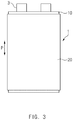
- FIG. 2 is a development view of the electrode assembly according to an embodiment of the present invention.
- the separator member 20 when the separator member 20 that wraps the electrode stack 10 is spread, the separator member 20 may include a first area 20a, a second area 20b, and a third area 20c, each of which has a width that corresponds to a width of the electrode stack 10 and is sequentially arranged.
- the separator member 20 may also include a fourth area 20d, which has a width less than the width of the electrode stack 10 and is continuously arranged to the third area 20c.
- the electrode stack 10 may be attached to each of the first area 20a and the third area 20c to space one electrode stack 10a apart from the other electrode stack 10b by the second area 20b.
- the separator member 20 may be rolled (R) to stack the plurality of electrode stacks 10 to allow the separator member 20 to wrap the circumferential portion of the electrode stack 10.
- the fourth area 20d wraps the electrode stack 10
- at least a portion of the fourth area 20d may wrap the electrode stack 10 to overlap the other area of the separator member 20.
- the separator member 20 may be fused to each other to allow the plurality of electrode stacks 10 to be fixed by the separator member 20 in the state in which the electrode stacks 10 are stacked.
- the plurality of electrode stacks 10 may be fixed to each other with strong adhesion.
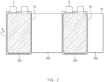
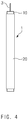
- FIG. 3 is a plan view of the electrode assembly according to an embodiment of the present invention
- FIG. 4 is a side view of FIG. 3 .
- the electrode assembly 1 includes a plurality of electrode stacks 10 that are stacked on each other and fixed by the separator member 20 and a separator member 20 that wraps and fixes the plurality of stacked electrode stacks 10.
- a separator member 20 that wraps and fixes the plurality of stacked electrode stacks 10.
- an electrode and a separator are alternately stacked.
- the electrode of the electrode stack 10 may include a positive electrode and a negative electrode which have polarities different from each other.
- the positive electrode may be an aluminum plate and include a positive electrode coating portion coated with the positive electrode active material and a positive electrode non-coating portion which is not coated with the positive electrode active material.
- the positive electrode active material may include a lithium-containing transition metal oxide such as LiCoO 2 , LiNiO 2 , LiMnO 2 , and LiMnO 4 or a lithium chalcogenide compound.
- a lithium-containing transition metal oxide such as LiCoO 2 , LiNiO 2 , LiMnO 2 , and LiMnO 4 or a lithium chalcogenide compound.
- the positive electrode coating portion may be formed, for example, by applying the positive electrode active material to a portion of at least one surface of the aluminum plate, and the remaining portion of the aluminum plate, which is not coated with the positive electrode active material, may be defined as the positive electrode non-coating portion.
- a positive electrode tab may be attached to the positive electrode non-coating portion.
- the negative electrode may be a copper plate and include a negative electrode coating portion coated with the negative electrode active material and a negative electrode non-coating portion which is not coated with the negative electrode active material.
- a negative electrode tab may be attached to the negative electrode non-coating portion.
- the negative electrode active material may be a carbon material such as crystalline carbon, amorphous carbon, a carbon composite, and a carbon fiber, a lithium metal, or a lithium alloy.
- the negative electrode coating portion may be formed, for example, by applying the negative electrode active material to a portion of at least one surface of the copper plate, and the remaining portion of the copper plate, which is not coated with the negative electrode active material, may be defined as the negative electrode non-coating portion.
- the separator may be manufactured by applying a polyvinylidene fluoride-hexafluoropropylene copolymer (PVDF-HFP co-polymer) to one base material selected from the group consisting of, for example, polyethylene (PE), polystyrene (PS), polypropylene (PP), and a copolymer of polyethylene (PE) and polypropylene.
- PVDF-HFP co-polymer polyvinylidene fluoride-hexafluoropropylene copolymer
- the electrode stack 10 may have a folded shape.
- the electrodes and the separators may be gathered together to form a unit having a folded shape.
- the separator member 20 may wrap a circumferential portion of surfaces, which are exposed to the outside, of the plurality of stacked electrode stacks 10.
- the separator member 20 may wrap a body portion except both ends of the electrode stack 10 in a direction P parallel to a direction in which an electrode lead 3 coupled to the electrode stack 10 protrudes.
- the configuration that wraps the body portion except both ends may be merely one embodiment, and thus, a configuration that wraps the body portion as well as the both ends may be also possible.
- the separator member 20 may be reduced in size to decrease manufacturing costs.
- the plurality of electrode stacks may be stacked at the predetermined thickness.
- the plurality of electrode stacks may be stacked with a strong adhesion.
- the plurality of electrode stacks may be stacked to prevent defects from occurring while the electrode assembly is manufactured.
- the plurality of electrode stacks may be stacked to manufacture the secondary battery with high energy.
- the fixing force may be significantly improved compared to a case in which the electrode stacks are fixed by a tape.
- the electrode stacks may be easily separated or rolled to be deformed during a degassing process.
- the electrode stacks may be maintained in the good state without being separated during the degassing process.
- a cosmetic appearance of a pouch may be significantly improved compared to the case in which the electrode stacks are fixed by the tape. In the attachment using the tape, marking may occur to deteriorate the cosmetic appearance.
Abstract
Description
- The present application claims the benefit of the priority of Korean Patent Application No.
10-2017-0044541 filed on April 06, 2017 - The present invention relates to an electrode assembly and a method for manufacturing the same, and more particularly, to an electrode assembly in which a plurality of electrode stacks are stacked to improve product reliability when manufactured and a method for manufacturing the same.
- Due to the living environment in which one is surrounded by various electric and electronic devices, batteries (cells) that generate electric energy through physical or chemical reaction to supply the generated electric energy to the outside are used when AC power is not supplied to the building, or DC power is required.
- Among such batteries, primary batteries and secondary batteries, which are chemical batteries using chemical reaction, are being generally used. The primary batteries are consumable batteries which are collectively referred to as dry batteries.
- Secondary batteries are rechargeable batteries that are manufactured using a material in which a redox process between electric current and a substance is repeatable plural times. When the reduction reaction is performed on the material by the electric current, power is charged, and when the oxidation reaction is performed on the material, power is discharged. The charging-discharging is repeatedly performed to generate electricity.
- A secondary battery that is improved in safety and capacity according to the related art is disclosed in Korea Patent Publication No.
10-2007-0120210 - An electrode assembly of a lithium secondary battery according to the related art has been expanded to a field that requires high energy such as vehicles, electric power storages, and the like from limited applications of electronic devices, using a plurality of electrode assemblies.
- Due to this necessity, a folding cell in which a plurality of electrode stacks are stacked has been manufactured.
- However, when the plurality of electrode stacks are stacked, there is a problem that the electrodes are broken due to a gap between the electrode stacks.
- Further, when the plurality of electrode stacks are stacked, there is a problem of increased frequency that protrusion of a positive electrode and a negative electrode from the electrode stacks occurs.
- Therefore, the present invention has been made to solve the above-mentioned problem, and an object of the prevent invention is to provide an electrode in which a plurality of electrode stacks are stacked at a predetermined thickness to improve adhesion and a method for manufacturing the same.
- A method for manufacturing an electrode assembly according to an embodiment of the present invention includes a preparation step of preparing a plurality of electrode stacks in which an electrode and a separator are alternately stacked; a stacking step of stacking the plurality of electrode stacks on each other; a packaging step of wrapping and packaging a circumferential potion of the plurality of stacked electrode stacks using a separator member; and a fixing step of heating and pressing the separator member to fix the plurality of stacked electrode stacks.
- In the preparation step, the folded electrode stacks may be prepared.
- In the preparation step, the electrode stacks having shapes different from each other may be prepared.
- In the fixing step, the separator member wound around the circumferential portion of the electrode stacks may be heated and pressed by a hot press.
- An electrode assembly according to an embodiment of the present invention includes a plurality of electrode stacks in which an electrode and a separator are alternately stacked; and a separator member that wraps and fixes the plurality of stacked electrode stacks.
- Each of the electrode stacks may have a folded shape.
- The separator member may be fused while wrapping the plurality of stacked electrode stacks.
- The separator member may wrap a circumferential portion of surfaces, which are exposed to the outside, of the plurality of stacked electrode stacks.
- The separator member may wrap a body portion except both ends of the electrode stacks in a direction parallel to a direction in which an electrode lead coupled to the electrode stacks protrudes.
- When the separator member that wraps the electrode stacks is spread, the separator member may include a first area, a second area, and a third area, which are sequentially arranged and each having a width that corresponds to a width of the electrode stacks, and a fourth area that is continuously arranged from the third area and having a width less than the width of the electrode stacks, and the electrode stacks may be attached to the first area and the third area.
- According to the present invention, the plurality of electrode stacks may be stacked at a predetermined thickness.
- According to the present invention, the plurality of electrode stacks may be stacked with the strong adhesion.
- According to the present invention, the plurality of electrode stacks may be stacked to prevent the defects from occurring while the electrode assembly is manufactured.
- According to the present invention, the plurality of electrode stacks may be stacked to manufacture the secondary battery having a high energy.
-
-
FIG. 1 is a flowchart illustrating a method for manufacturing an electrode assembly according to an embodiment of the present invention. -
FIG. 2 is a development view of the electrode assembly according to an embodiment of the present invention. -
FIG. 3 is a plan view of the electrode assembly according to an embodiment of the present invention. -
FIG. 4 is a side view ofFIG. 3 . - Hereinafter, a secondary battery and a method for manufacturing the same according to preferred embodiments of the present invention will be described in detail with reference to the accompanying drawings.
- Terms or words used in the specification and claims should not be construed as limited to a lexical meaning, and should be understood as appropriate notions by the inventor based on that he/she is able to define terms to describe his/her invention in the best way to be seen by others. Therefore, embodiments and drawings described herein are simply exemplary and not exhaustive, and it will be understood that various equivalents may be made to take the place of the embodiments.
- In the drawings, the dimension of each of components or a specific portion constituting the component is exaggerated, omitted, or schematically illustrated for convenience in description and clarity. Thus, the dimension of each element does not entirely reflect an actual size. Moreover, detailed descriptions related to well-known functions or configurations will be ruled out in order not to unnecessarily obscure subject matters of the present invention.
-
FIG. 1 is a flowchart illustrating a method for manufacturing an electrode assembly according to an embodiment of the present invention. - As illustrated in
FIG. 1 , a method for manufacturing an electrode assembly according to an embodiment of the present invention includes a preparation step (S1), a stacking step (S2), a packaging step (S3), and a fixing step (S4). - The preparation step (S1) may be a step of preparing a plurality of electrode stacks 10 in which an electrode and a separator are alternately stacked.
- In addition, each of the electrode stacks 10 prepared in the preparation step (S1) may be in a folded state.
- Further, the electrode stacks 10 prepared in the preparation step (S1) may have shapes different from each other.
- The stacking step (S2) is a step of stacking the plurality of
electrode stacks 10. - The packaging step (S3) is a step of wrapping and packaging the plurality of electrode stacks 10 stacked in the stacking step (S2) using a
separator member 20. - The stacking step (S2) and the packaging step (S3) may be performed at the same time.
- The fixing step (S4) is a step of heating and pressing the
separator member 20 that wraps the electrode stacks 10 to fix the plurality of stacked electrode stacks 10 to fuse and bond theseparator member 20. - In the fixing step (S4), the
separator member 20 wound around a circumferential portion of theelectrode stack 10 may be heated and pressed using a hot press to be fixed. -
FIG. 2 is a development view of the electrode assembly according to an embodiment of the present invention. - As illustrated in
FIG. 2 , when theseparator member 20 that wraps theelectrode stack 10 is spread, theseparator member 20 may include afirst area 20a, asecond area 20b, and athird area 20c, each of which has a width that corresponds to a width of theelectrode stack 10 and is sequentially arranged. Theseparator member 20 may also include afourth area 20d, which has a width less than the width of theelectrode stack 10 and is continuously arranged to thethird area 20c. - The
electrode stack 10 may be attached to each of thefirst area 20a and thethird area 20c to space one electrode stack 10a apart from the other electrode stack 10b by thesecond area 20b. - The
separator member 20 may be rolled (R) to stack the plurality ofelectrode stacks 10 to allow theseparator member 20 to wrap the circumferential portion of theelectrode stack 10. - When the
fourth area 20d wraps theelectrode stack 10, at least a portion of thefourth area 20d may wrap theelectrode stack 10 to overlap the other area of theseparator member 20. Further, when the overlapping portion between thefourth area 20d and the other area of theseparator member 20 is heated and pressed by the hot press, theseparator member 20 may be fused to each other to allow the plurality ofelectrode stacks 10 to be fixed by theseparator member 20 in the state in which theelectrode stacks 10 are stacked. - Thus, the plurality of
electrode stacks 10 may be fixed to each other with strong adhesion. -
FIG. 3 is a plan view of the electrode assembly according to an embodiment of the present invention, andFIG. 4 is a side view ofFIG. 3 . - As illustrated in
FIGS. 3 and4 , theelectrode assembly 1 according to the present invention includes a plurality of electrode stacks 10 that are stacked on each other and fixed by theseparator member 20 and aseparator member 20 that wraps and fixes the plurality of stacked electrode stacks 10. In each of the electrode stacks 10, an electrode and a separator are alternately stacked. - The electrode of the
electrode stack 10 may include a positive electrode and a negative electrode which have polarities different from each other. - The positive electrode may be an aluminum plate and include a positive electrode coating portion coated with the positive electrode active material and a positive electrode non-coating portion which is not coated with the positive electrode active material.
- The positive electrode active material may include a lithium-containing transition metal oxide such as LiCoO2, LiNiO2, LiMnO2, and LiMnO4 or a lithium chalcogenide compound.
- The positive electrode coating portion may be formed, for example, by applying the positive electrode active material to a portion of at least one surface of the aluminum plate, and the remaining portion of the aluminum plate, which is not coated with the positive electrode active material, may be defined as the positive electrode non-coating portion.
- A positive electrode tab may be attached to the positive electrode non-coating portion.
- The negative electrode may be a copper plate and include a negative electrode coating portion coated with the negative electrode active material and a negative electrode non-coating portion which is not coated with the negative electrode active material.
- A negative electrode tab may be attached to the negative electrode non-coating portion.
- The negative electrode active material may be a carbon material such as crystalline carbon, amorphous carbon, a carbon composite, and a carbon fiber, a lithium metal, or a lithium alloy.
- The negative electrode coating portion may be formed, for example, by applying the negative electrode active material to a portion of at least one surface of the copper plate, and the remaining portion of the copper plate, which is not coated with the negative electrode active material, may be defined as the negative electrode non-coating portion.
- In addition, the separator may be manufactured by applying a polyvinylidene fluoride-hexafluoropropylene copolymer (PVDF-HFP co-polymer) to one base material selected from the group consisting of, for example, polyethylene (PE), polystyrene (PS), polypropylene (PP), and a copolymer of polyethylene (PE) and polypropylene.
- The
electrode stack 10 may have a folded shape. The electrodes and the separators may be gathered together to form a unit having a folded shape. - The
separator member 20 may wrap a circumferential portion of surfaces, which are exposed to the outside, of the plurality of stacked electrode stacks 10. - Alternatively, the
separator member 20 may wrap a body portion except both ends of theelectrode stack 10 in a direction P parallel to a direction in which anelectrode lead 3 coupled to theelectrode stack 10 protrudes. The configuration that wraps the body portion except both ends may be merely one embodiment, and thus, a configuration that wraps the body portion as well as the both ends may be also possible. - However, when the body portion except both ends is wrapped, the
separator member 20 may be reduced in size to decrease manufacturing costs. - As described above, according to the present invention, the plurality of electrode stacks may be stacked at the predetermined thickness.
- According to the present invention, the plurality of electrode stacks may be stacked with a strong adhesion.
- According to the present invention, the plurality of electrode stacks may be stacked to prevent defects from occurring while the electrode assembly is manufactured.
- According to the present invention, the plurality of electrode stacks may be stacked to manufacture the secondary battery with high energy.
- According to the present invention, the fixing force may be significantly improved compared to a case in which the electrode stacks are fixed by a tape. In the case of using a tape, the electrode stacks may be easily separated or rolled to be deformed during a degassing process. However, according to the present invention, the electrode stacks may be maintained in the good state without being separated during the degassing process.
- Moreover, a cosmetic appearance of a pouch may be significantly improved compared to the case in which the electrode stacks are fixed by the tape. In the attachment using the tape, marking may occur to deteriorate the cosmetic appearance.
- Although the electrode assembly and the method for manufacturing the same according to the present invention has been described above with reference to the exemplary drawings, various changes and modifications may be made thereto by one skilled in the art without departing from the scope and spirit of the invention as set forth in the appended claims.
Claims (10)
- A method for manufacturing an electrode assembly, the method comprising:a preparation step (S1) of preparing a plurality of electrode stacks (10) in which an electrode and a separator are alternately stacked;a stacking step (S2) of stacking the plurality of electrode stacks (10) on each other;a packaging step (S3) of wrapping and packaging a circumferential potion of the plurality of stacked electrode stacks (10) using a separator member (20); anda fixing step (S4) of heating and pressing the separator member (20) to fix the plurality of stacked electrode stacks (10).
- The method of claim 1, wherein, in the preparation step (S1), the folded electrode stacks (10) are prepared.
- The method of claim 1, wherein, in the preparation step (S1), the electrode stacks (10) having shapes different from each other are prepared.
- The method of claim 1, wherein, in the fixing step (S4), the separator member (20) wound around the circumferential portion of the electrode stacks (10) is heated and pressed by a hot press.
- An electrode assembly comprising:a plurality of electrode stacks (10) in which an electrode and a separator are alternately stacked; anda separator member (20) that wraps and fixes the plurality of stacked electrode stacks (10).
- The electrode assembly of claim 5, wherein each of the electrode stacks (10) has a folded shape.
- The electrode assembly of claim 5, wherein the separator member (20) is fused while wrapping the plurality of stacked electrode stacks (10).
- The electrode assembly of claim 5, wherein the separator member (20) wraps a circumferential portion of surfaces, which are exposed to the outside, of the plurality of stacked electrode stacks (10).
- The electrode assembly of claim 5, wherein the separator member (20) wraps a body portion except both ends of the electrode stacks (10) in a direction (P) parallel to a direction in which an electrode lead (3) coupled to the electrode stacks (10) protrudes.
- The electrode assembly of claim 5, wherein, when the separator member (20) that wraps the electrode stacks (10) is spread, the separator member (20) comprises a first area (20a), a second area (20b), and a third area (20c), which are sequentially arranged and have a width that corresponds to a width of the electrode stack (10), and a fourth area (20d), which is arranged continuously from the third area (20c) and has a width less than the width of the electrode stacks (10), and
the electrode stacks (10) are attached to the first area (20a) and the third area (20c).
Priority Applications (1)
| Application Number | Priority Date | Filing Date | Title |
|---|---|---|---|
| PL18781861T PL3598554T3 (en) | 2017-04-06 | 2018-01-29 | Electrode assembly and method for manufacturing electrode assembly |
Applications Claiming Priority (2)
| Application Number | Priority Date | Filing Date | Title |
|---|---|---|---|
| KR1020170044541A KR102217444B1 (en) | 2017-04-06 | 2017-04-06 | Electrode assembly and manufactureing method for the same |
| PCT/KR2018/001252 WO2018186576A1 (en) | 2017-04-06 | 2018-01-29 | Electrode assembly and method for manufacturing electrode assembly |
Publications (3)
| Publication Number | Publication Date |
|---|---|
| EP3598554A1 true EP3598554A1 (en) | 2020-01-22 |
| EP3598554A4 EP3598554A4 (en) | 2020-05-06 |
| EP3598554B1 EP3598554B1 (en) | 2021-10-20 |
Family
ID=63712160
Family Applications (1)
| Application Number | Title | Priority Date | Filing Date |
|---|---|---|---|
| EP18781861.2A Active EP3598554B1 (en) | 2017-04-06 | 2018-01-29 | Electrode assembly and method for manufacturing electrode assembly |
Country Status (6)
| Country | Link |
|---|---|
| US (1) | US11251502B2 (en) |
| EP (1) | EP3598554B1 (en) |
| KR (1) | KR102217444B1 (en) |
| CN (1) | CN109923723B (en) |
| PL (1) | PL3598554T3 (en) |
| WO (1) | WO2018186576A1 (en) |
Cited By (1)
| Publication number | Priority date | Publication date | Assignee | Title |
|---|---|---|---|---|
| WO2023072942A3 (en) * | 2021-10-29 | 2023-07-27 | Volkswagen Aktiengesellschaft | Method and device for laminating components of a battery cell |
Family Cites Families (22)
| Publication number | Priority date | Publication date | Assignee | Title |
|---|---|---|---|---|
| KR100497147B1 (en) * | 2000-02-08 | 2005-06-29 | 주식회사 엘지화학 | Multiply stacked electrochemical cell and method for preparing the same |
| KR100555848B1 (en) | 2003-04-25 | 2006-03-03 | 주식회사 에너랜드 | Fabrication of stacked type lithium secondary battery which enables to attach electrode plates in one direction |
| JP2006019075A (en) | 2004-06-30 | 2006-01-19 | Nissan Motor Co Ltd | Flat type battery and battery pack using its battery |
| KR100871345B1 (en) | 2006-06-19 | 2008-12-01 | 주식회사 엘지화학 | Secondary Battery of Improved Safety and Capacity |
| KR100907622B1 (en) | 2006-08-14 | 2009-07-15 | 주식회사 엘지화학 | Secondary battery with excellent safety against external shock and electrolyte impregnation |
| JP2008293681A (en) * | 2007-05-22 | 2008-12-04 | Hitachi Vehicle Energy Ltd | Lithium-ion secondary battery |
| JP5132269B2 (en) * | 2007-11-13 | 2013-01-30 | 日立ビークルエナジー株式会社 | Lithium ion secondary battery |
| KR101014817B1 (en) | 2007-12-14 | 2011-02-14 | 주식회사 엘지화학 | stack/folding-typed Electrode Assembly Containing Safety Member and Process for Preparation of the Same |
| KR20110053835A (en) | 2009-11-16 | 2011-05-24 | 삼성에스디아이 주식회사 | Lithium polymer secondary battery |
| JP2011138675A (en) * | 2009-12-28 | 2011-07-14 | Panasonic Corp | Electrode group for nonaqueous secondary battery, and nonaqueous secondary battery using the same |
| JP5583421B2 (en) * | 2010-02-10 | 2014-09-03 | 三洋電機株式会社 | Square sealed secondary battery and method for manufacturing square sealed secondary battery |
| JP2011210522A (en) | 2010-03-30 | 2011-10-20 | Sanyo Electric Co Ltd | Battery pack |
| JP2013008550A (en) * | 2011-06-24 | 2013-01-10 | Sharp Corp | Secondary battery and manufacturing method thereof |
| KR101332282B1 (en) * | 2012-03-14 | 2013-11-22 | 주식회사 엘지화학 | Electrode Assembly of Novel Structure and Battery Cell Comprising the Same |
| WO2014003481A1 (en) | 2012-06-28 | 2014-01-03 | 주식회사 엘지화학 | Electrode assembly and electrochemical device containing same |
| KR101406038B1 (en) * | 2012-09-11 | 2014-06-13 | 주식회사 루트제이드 | Wrapping electrode plate for use in lithium ion secondary battery and manufacturing method of the same |
| KR101617495B1 (en) | 2013-03-04 | 2016-05-03 | 주식회사 엘지화학 | Method for Preparing a Jelly-Roll Type Electrode Assembly and a Secondary Battery |
| KR101736543B1 (en) | 2014-06-30 | 2017-05-16 | 주식회사 엘지화학 | Electrode assembly |
| KR101730318B1 (en) | 2014-07-07 | 2017-05-11 | 주식회사 엘지화학 | Battery Cell Having Separation Film of Suppressed Thermal Shrinkage |
| KR101847679B1 (en) * | 2014-11-17 | 2018-04-10 | 주식회사 엘지화학 | Electrode assembly for secondary battery and secondary battery comprising the same |
| CN105576296B (en) * | 2016-03-11 | 2019-01-08 | 合肥国轩高科动力能源有限公司 | A kind of takeup type laminated batteries and preparation method thereof |
| CN205646031U (en) * | 2016-05-07 | 2016-10-12 | 合肥国轩高科动力能源有限公司 | Monomer electrode subassembly arranges bonding device |
-
2017
- 2017-04-06 KR KR1020170044541A patent/KR102217444B1/en active IP Right Grant
-
2018
- 2018-01-29 PL PL18781861T patent/PL3598554T3/en unknown
- 2018-01-29 WO PCT/KR2018/001252 patent/WO2018186576A1/en unknown
- 2018-01-29 EP EP18781861.2A patent/EP3598554B1/en active Active
- 2018-01-29 CN CN201880004288.6A patent/CN109923723B/en active Active
- 2018-01-29 US US16/340,652 patent/US11251502B2/en active Active
Cited By (1)
| Publication number | Priority date | Publication date | Assignee | Title |
|---|---|---|---|---|
| WO2023072942A3 (en) * | 2021-10-29 | 2023-07-27 | Volkswagen Aktiengesellschaft | Method and device for laminating components of a battery cell |
Also Published As
| Publication number | Publication date |
|---|---|
| CN109923723B (en) | 2022-03-25 |
| WO2018186576A1 (en) | 2018-10-11 |
| PL3598554T3 (en) | 2022-01-24 |
| CN109923723A (en) | 2019-06-21 |
| US11251502B2 (en) | 2022-02-15 |
| KR102217444B1 (en) | 2021-02-22 |
| EP3598554A4 (en) | 2020-05-06 |
| EP3598554B1 (en) | 2021-10-20 |
| KR20180113252A (en) | 2018-10-16 |
| US20200052275A1 (en) | 2020-02-13 |
Similar Documents
| Publication | Publication Date | Title |
|---|---|---|
| US11652232B2 (en) | Secondary battery and method for manufacturing the same | |
| US8017264B2 (en) | Lithium secondary battery with high safety and manufacturing method thereof | |
| US11349182B2 (en) | Electrode assembly | |
| EP3905417A1 (en) | Method for manufacturing electrode assembly, and electrode and secondary battery manufactured thereby | |
| KR101651712B1 (en) | Secondary Battery | |
| EP3609010B1 (en) | System and method for manufacturing secondary battery | |
| EP3731322A1 (en) | Electrode assembly manufacturing method and secondary battery manufacturing method | |
| EP3401992B1 (en) | Secondary battery | |
| EP3598554B1 (en) | Electrode assembly and method for manufacturing electrode assembly | |
| US11056714B2 (en) | Secondary battery | |
| KR102010037B1 (en) | Sealing tool and manufacturing method for pouch type secondary battery | |
| US11973177B2 (en) | Secondary battery and method for manufacturing the same | |
| EP3514877B1 (en) | Electrode assembly and manufacturing method for electrode assembly | |
| US20230143528A1 (en) | Electrode Assembly and Method for Manufacturing Same | |
| KR102340101B1 (en) | Battery and method for manufcturing the same | |
| KR20230052713A (en) | Electrode for Lithium Secondary Battery with Adhesive Coating and Method for Manufacturing the Same |
Legal Events
| Date | Code | Title | Description |
|---|---|---|---|
| STAA | Information on the status of an ep patent application or granted ep patent |
Free format text: STATUS: THE INTERNATIONAL PUBLICATION HAS BEEN MADE |
|
| PUAI | Public reference made under article 153(3) epc to a published international application that has entered the european phase |
Free format text: ORIGINAL CODE: 0009012 |
|
| STAA | Information on the status of an ep patent application or granted ep patent |
Free format text: STATUS: REQUEST FOR EXAMINATION WAS MADE |
|
| 17P | Request for examination filed |
Effective date: 20190417 |
|
| AK | Designated contracting states |
Kind code of ref document: A1 Designated state(s): AL AT BE BG CH CY CZ DE DK EE ES FI FR GB GR HR HU IE IS IT LI LT LU LV MC MK MT NL NO PL PT RO RS SE SI SK SM TR |
|
| AX | Request for extension of the european patent |
Extension state: BA ME |
|
| A4 | Supplementary search report drawn up and despatched |
Effective date: 20200406 |
|
| RIC1 | Information provided on ipc code assigned before grant |
Ipc: H01M 10/04 20060101AFI20200331BHEP Ipc: H01M 2/02 20060101ALI20200331BHEP Ipc: H01M 10/0585 20100101ALI20200331BHEP Ipc: H01M 10/0583 20100101ALI20200331BHEP Ipc: H01M 2/04 20060101ALI20200331BHEP Ipc: H01M 10/058 20100101ALI20200331BHEP |
|
| DAV | Request for validation of the european patent (deleted) | ||
| DAX | Request for extension of the european patent (deleted) | ||
| STAA | Information on the status of an ep patent application or granted ep patent |
Free format text: STATUS: EXAMINATION IS IN PROGRESS |
|
| 17Q | First examination report despatched |
Effective date: 20201016 |
|
| STAA | Information on the status of an ep patent application or granted ep patent |
Free format text: STATUS: EXAMINATION IS IN PROGRESS |
|
| REG | Reference to a national code |
Ref country code: DE Ref legal event code: R079 Ref document number: 602018025405 Country of ref document: DE Free format text: PREVIOUS MAIN CLASS: H01M0010040000 Ipc: H01M0050147000 |
|
| GRAP | Despatch of communication of intention to grant a patent |
Free format text: ORIGINAL CODE: EPIDOSNIGR1 |
|
| STAA | Information on the status of an ep patent application or granted ep patent |
Free format text: STATUS: GRANT OF PATENT IS INTENDED |
|
| RIC1 | Information provided on ipc code assigned before grant |
Ipc: H01M 10/0583 20100101ALI20210504BHEP Ipc: H01M 10/0585 20100101ALI20210504BHEP Ipc: H01M 10/058 20100101ALI20210504BHEP Ipc: H01M 10/04 20060101ALI20210504BHEP Ipc: H01M 50/10 20210101ALI20210504BHEP Ipc: H01M 50/147 20210101AFI20210504BHEP |
|
| INTG | Intention to grant announced |
Effective date: 20210526 |
|
| GRAS | Grant fee paid |
Free format text: ORIGINAL CODE: EPIDOSNIGR3 |
|
| GRAA | (expected) grant |
Free format text: ORIGINAL CODE: 0009210 |
|
| STAA | Information on the status of an ep patent application or granted ep patent |
Free format text: STATUS: THE PATENT HAS BEEN GRANTED |
|
| AK | Designated contracting states |
Kind code of ref document: B1 Designated state(s): AL AT BE BG CH CY CZ DE DK EE ES FI FR GB GR HR HU IE IS IT LI LT LU LV MC MK MT NL NO PL PT RO RS SE SI SK SM TR |
|
| REG | Reference to a national code |
Ref country code: GB Ref legal event code: FG4D |
|
| REG | Reference to a national code |
Ref country code: CH Ref legal event code: EP |
|
| REG | Reference to a national code |
Ref country code: DE Ref legal event code: R096 Ref document number: 602018025405 Country of ref document: DE |
|
| REG | Reference to a national code |
Ref country code: IE Ref legal event code: FG4D |
|
| REG | Reference to a national code |
Ref country code: AT Ref legal event code: REF Ref document number: 1440663 Country of ref document: AT Kind code of ref document: T Effective date: 20211115 |
|
| REG | Reference to a national code |
Ref country code: SE Ref legal event code: TRGR |
|
| RAP2 | Party data changed (patent owner data changed or rights of a patent transferred) |
Owner name: LG ENERGY SOLUTION LTD. |
|
| REG | Reference to a national code |
Ref country code: LT Ref legal event code: MG9D |
|
| REG | Reference to a national code |
Ref country code: NL Ref legal event code: MP Effective date: 20211020 |
|
| REG | Reference to a national code |
Ref country code: AT Ref legal event code: MK05 Ref document number: 1440663 Country of ref document: AT Kind code of ref document: T Effective date: 20211020 |
|
| RAP4 | Party data changed (patent owner data changed or rights of a patent transferred) |
Owner name: LG ENERGY SOLUTION, LTD. |
|
| PG25 | Lapsed in a contracting state [announced via postgrant information from national office to epo] |
Ref country code: RS Free format text: LAPSE BECAUSE OF FAILURE TO SUBMIT A TRANSLATION OF THE DESCRIPTION OR TO PAY THE FEE WITHIN THE PRESCRIBED TIME-LIMIT Effective date: 20211020 Ref country code: LT Free format text: LAPSE BECAUSE OF FAILURE TO SUBMIT A TRANSLATION OF THE DESCRIPTION OR TO PAY THE FEE WITHIN THE PRESCRIBED TIME-LIMIT Effective date: 20211020 Ref country code: FI Free format text: LAPSE BECAUSE OF FAILURE TO SUBMIT A TRANSLATION OF THE DESCRIPTION OR TO PAY THE FEE WITHIN THE PRESCRIBED TIME-LIMIT Effective date: 20211020 Ref country code: BG Free format text: LAPSE BECAUSE OF FAILURE TO SUBMIT A TRANSLATION OF THE DESCRIPTION OR TO PAY THE FEE WITHIN THE PRESCRIBED TIME-LIMIT Effective date: 20220120 Ref country code: AT Free format text: LAPSE BECAUSE OF FAILURE TO SUBMIT A TRANSLATION OF THE DESCRIPTION OR TO PAY THE FEE WITHIN THE PRESCRIBED TIME-LIMIT Effective date: 20211020 |
|
| PG25 | Lapsed in a contracting state [announced via postgrant information from national office to epo] |
Ref country code: IS Free format text: LAPSE BECAUSE OF FAILURE TO SUBMIT A TRANSLATION OF THE DESCRIPTION OR TO PAY THE FEE WITHIN THE PRESCRIBED TIME-LIMIT Effective date: 20220220 Ref country code: PT Free format text: LAPSE BECAUSE OF FAILURE TO SUBMIT A TRANSLATION OF THE DESCRIPTION OR TO PAY THE FEE WITHIN THE PRESCRIBED TIME-LIMIT Effective date: 20220221 Ref country code: NO Free format text: LAPSE BECAUSE OF FAILURE TO SUBMIT A TRANSLATION OF THE DESCRIPTION OR TO PAY THE FEE WITHIN THE PRESCRIBED TIME-LIMIT Effective date: 20220120 Ref country code: NL Free format text: LAPSE BECAUSE OF FAILURE TO SUBMIT A TRANSLATION OF THE DESCRIPTION OR TO PAY THE FEE WITHIN THE PRESCRIBED TIME-LIMIT Effective date: 20211020 Ref country code: LV Free format text: LAPSE BECAUSE OF FAILURE TO SUBMIT A TRANSLATION OF THE DESCRIPTION OR TO PAY THE FEE WITHIN THE PRESCRIBED TIME-LIMIT Effective date: 20211020 Ref country code: HR Free format text: LAPSE BECAUSE OF FAILURE TO SUBMIT A TRANSLATION OF THE DESCRIPTION OR TO PAY THE FEE WITHIN THE PRESCRIBED TIME-LIMIT Effective date: 20211020 Ref country code: GR Free format text: LAPSE BECAUSE OF FAILURE TO SUBMIT A TRANSLATION OF THE DESCRIPTION OR TO PAY THE FEE WITHIN THE PRESCRIBED TIME-LIMIT Effective date: 20220121 Ref country code: ES Free format text: LAPSE BECAUSE OF FAILURE TO SUBMIT A TRANSLATION OF THE DESCRIPTION OR TO PAY THE FEE WITHIN THE PRESCRIBED TIME-LIMIT Effective date: 20211020 |
|
| REG | Reference to a national code |
Ref country code: DE Ref legal event code: R097 Ref document number: 602018025405 Country of ref document: DE |
|
| PG25 | Lapsed in a contracting state [announced via postgrant information from national office to epo] |
Ref country code: SM Free format text: LAPSE BECAUSE OF FAILURE TO SUBMIT A TRANSLATION OF THE DESCRIPTION OR TO PAY THE FEE WITHIN THE PRESCRIBED TIME-LIMIT Effective date: 20211020 Ref country code: SK Free format text: LAPSE BECAUSE OF FAILURE TO SUBMIT A TRANSLATION OF THE DESCRIPTION OR TO PAY THE FEE WITHIN THE PRESCRIBED TIME-LIMIT Effective date: 20211020 Ref country code: RO Free format text: LAPSE BECAUSE OF FAILURE TO SUBMIT A TRANSLATION OF THE DESCRIPTION OR TO PAY THE FEE WITHIN THE PRESCRIBED TIME-LIMIT Effective date: 20211020 Ref country code: EE Free format text: LAPSE BECAUSE OF FAILURE TO SUBMIT A TRANSLATION OF THE DESCRIPTION OR TO PAY THE FEE WITHIN THE PRESCRIBED TIME-LIMIT Effective date: 20211020 Ref country code: DK Free format text: LAPSE BECAUSE OF FAILURE TO SUBMIT A TRANSLATION OF THE DESCRIPTION OR TO PAY THE FEE WITHIN THE PRESCRIBED TIME-LIMIT Effective date: 20211020 Ref country code: CZ Free format text: LAPSE BECAUSE OF FAILURE TO SUBMIT A TRANSLATION OF THE DESCRIPTION OR TO PAY THE FEE WITHIN THE PRESCRIBED TIME-LIMIT Effective date: 20211020 |
|
| PLBE | No opposition filed within time limit |
Free format text: ORIGINAL CODE: 0009261 |
|
| STAA | Information on the status of an ep patent application or granted ep patent |
Free format text: STATUS: NO OPPOSITION FILED WITHIN TIME LIMIT |
|
| PG25 | Lapsed in a contracting state [announced via postgrant information from national office to epo] |
Ref country code: MC Free format text: LAPSE BECAUSE OF FAILURE TO SUBMIT A TRANSLATION OF THE DESCRIPTION OR TO PAY THE FEE WITHIN THE PRESCRIBED TIME-LIMIT Effective date: 20211020 |
|
| REG | Reference to a national code |
Ref country code: CH Ref legal event code: PL |
|
| 26N | No opposition filed |
Effective date: 20220721 |
|
| REG | Reference to a national code |
Ref country code: BE Ref legal event code: MM Effective date: 20220131 |
|
| PG25 | Lapsed in a contracting state [announced via postgrant information from national office to epo] |
Ref country code: LU Free format text: LAPSE BECAUSE OF NON-PAYMENT OF DUE FEES Effective date: 20220129 Ref country code: AL Free format text: LAPSE BECAUSE OF FAILURE TO SUBMIT A TRANSLATION OF THE DESCRIPTION OR TO PAY THE FEE WITHIN THE PRESCRIBED TIME-LIMIT Effective date: 20211020 |
|
| PG25 | Lapsed in a contracting state [announced via postgrant information from national office to epo] |
Ref country code: SI Free format text: LAPSE BECAUSE OF FAILURE TO SUBMIT A TRANSLATION OF THE DESCRIPTION OR TO PAY THE FEE WITHIN THE PRESCRIBED TIME-LIMIT Effective date: 20211020 Ref country code: BE Free format text: LAPSE BECAUSE OF NON-PAYMENT OF DUE FEES Effective date: 20220131 |
|
| PG25 | Lapsed in a contracting state [announced via postgrant information from national office to epo] |
Ref country code: LI Free format text: LAPSE BECAUSE OF NON-PAYMENT OF DUE FEES Effective date: 20220131 Ref country code: CH Free format text: LAPSE BECAUSE OF NON-PAYMENT OF DUE FEES Effective date: 20220131 |
|
| PG25 | Lapsed in a contracting state [announced via postgrant information from national office to epo] |
Ref country code: IE Free format text: LAPSE BECAUSE OF NON-PAYMENT OF DUE FEES Effective date: 20220129 |
|
| PGFP | Annual fee paid to national office [announced via postgrant information from national office to epo] |
Ref country code: PL Payment date: 20221221 Year of fee payment: 6 |
|
| REG | Reference to a national code |
Ref country code: DE Ref legal event code: R081 Ref document number: 602018025405 Country of ref document: DE Owner name: LG ENERGY SOLUTION, LTD., KR Free format text: FORMER OWNER: LG CHEM, LTD., SEOUL, KR |
|
| PG25 | Lapsed in a contracting state [announced via postgrant information from national office to epo] |
Ref country code: IT Free format text: LAPSE BECAUSE OF FAILURE TO SUBMIT A TRANSLATION OF THE DESCRIPTION OR TO PAY THE FEE WITHIN THE PRESCRIBED TIME-LIMIT Effective date: 20211020 |
|
| PGFP | Annual fee paid to national office [announced via postgrant information from national office to epo] |
Ref country code: DE Payment date: 20221220 Year of fee payment: 6 |
|
| P01 | Opt-out of the competence of the unified patent court (upc) registered |
Effective date: 20230408 |
|
| REG | Reference to a national code |
Ref country code: GB Ref legal event code: 732E Free format text: REGISTERED BETWEEN 20230901 AND 20230906 |
|
| PGFP | Annual fee paid to national office [announced via postgrant information from national office to epo] |
Ref country code: GB Payment date: 20231220 Year of fee payment: 7 |
|
| PGFP | Annual fee paid to national office [announced via postgrant information from national office to epo] |
Ref country code: SE Payment date: 20231220 Year of fee payment: 7 Ref country code: FR Payment date: 20231222 Year of fee payment: 7 |
|
| PGFP | Annual fee paid to national office [announced via postgrant information from national office to epo] |
Ref country code: PL Payment date: 20231222 Year of fee payment: 7 |