EP3598553B1 - Sealed battery, battery pack and battery for engine ignition - Google Patents
Sealed battery, battery pack and battery for engine ignition Download PDFInfo
- Publication number
- EP3598553B1 EP3598553B1 EP18766602.9A EP18766602A EP3598553B1 EP 3598553 B1 EP3598553 B1 EP 3598553B1 EP 18766602 A EP18766602 A EP 18766602A EP 3598553 B1 EP3598553 B1 EP 3598553B1
- Authority
- EP
- European Patent Office
- Prior art keywords
- case
- battery
- electrode
- lead terminal
- section
- Prior art date
- Legal status (The legal status is an assumption and is not a legal conclusion. Google has not performed a legal analysis and makes no representation as to the accuracy of the status listed.)
- Active
Links
Images


Classifications
-
- H—ELECTRICITY
- H01—ELECTRIC ELEMENTS
- H01M—PROCESSES OR MEANS, e.g. BATTERIES, FOR THE DIRECT CONVERSION OF CHEMICAL ENERGY INTO ELECTRICAL ENERGY
- H01M50/00—Constructional details or processes of manufacture of the non-active parts of electrochemical cells other than fuel cells, e.g. hybrid cells
- H01M50/10—Primary casings; Jackets or wrappings
- H01M50/172—Arrangements of electric connectors penetrating the casing
-
- F—MECHANICAL ENGINEERING; LIGHTING; HEATING; WEAPONS; BLASTING
- F02—COMBUSTION ENGINES; HOT-GAS OR COMBUSTION-PRODUCT ENGINE PLANTS
- F02N—STARTING OF COMBUSTION ENGINES; STARTING AIDS FOR SUCH ENGINES, NOT OTHERWISE PROVIDED FOR
- F02N11/00—Starting of engines by means of electric motors
- F02N11/08—Circuits specially adapted for starting of engines
- F02N11/0862—Circuits specially adapted for starting of engines characterised by the electrical power supply means, e.g. battery
-
- H—ELECTRICITY
- H01—ELECTRIC ELEMENTS
- H01M—PROCESSES OR MEANS, e.g. BATTERIES, FOR THE DIRECT CONVERSION OF CHEMICAL ENERGY INTO ELECTRICAL ENERGY
- H01M10/00—Secondary cells; Manufacture thereof
- H01M10/04—Construction or manufacture in general
-
- H—ELECTRICITY
- H01—ELECTRIC ELEMENTS
- H01M—PROCESSES OR MEANS, e.g. BATTERIES, FOR THE DIRECT CONVERSION OF CHEMICAL ENERGY INTO ELECTRICAL ENERGY
- H01M10/00—Secondary cells; Manufacture thereof
- H01M10/04—Construction or manufacture in general
- H01M10/0413—Large-sized flat cells or batteries for motive or stationary systems with plate-like electrodes
-
- H—ELECTRICITY
- H01—ELECTRIC ELEMENTS
- H01M—PROCESSES OR MEANS, e.g. BATTERIES, FOR THE DIRECT CONVERSION OF CHEMICAL ENERGY INTO ELECTRICAL ENERGY
- H01M10/00—Secondary cells; Manufacture thereof
- H01M10/60—Heating or cooling; Temperature control
- H01M10/61—Types of temperature control
- H01M10/613—Cooling or keeping cold
-
- H—ELECTRICITY
- H01—ELECTRIC ELEMENTS
- H01M—PROCESSES OR MEANS, e.g. BATTERIES, FOR THE DIRECT CONVERSION OF CHEMICAL ENERGY INTO ELECTRICAL ENERGY
- H01M10/00—Secondary cells; Manufacture thereof
- H01M10/60—Heating or cooling; Temperature control
- H01M10/62—Heating or cooling; Temperature control specially adapted for specific applications
- H01M10/625—Vehicles
-
- H—ELECTRICITY
- H01—ELECTRIC ELEMENTS
- H01M—PROCESSES OR MEANS, e.g. BATTERIES, FOR THE DIRECT CONVERSION OF CHEMICAL ENERGY INTO ELECTRICAL ENERGY
- H01M10/00—Secondary cells; Manufacture thereof
- H01M10/60—Heating or cooling; Temperature control
- H01M10/65—Means for temperature control structurally associated with the cells
- H01M10/651—Means for temperature control structurally associated with the cells characterised by parameters specified by a numeric value or mathematical formula, e.g. ratios, sizes or concentrations
-
- H—ELECTRICITY
- H01—ELECTRIC ELEMENTS
- H01M—PROCESSES OR MEANS, e.g. BATTERIES, FOR THE DIRECT CONVERSION OF CHEMICAL ENERGY INTO ELECTRICAL ENERGY
- H01M10/00—Secondary cells; Manufacture thereof
- H01M10/60—Heating or cooling; Temperature control
- H01M10/65—Means for temperature control structurally associated with the cells
- H01M10/655—Solid structures for heat exchange or heat conduction
- H01M10/6553—Terminals or leads
-
- H—ELECTRICITY
- H01—ELECTRIC ELEMENTS
- H01M—PROCESSES OR MEANS, e.g. BATTERIES, FOR THE DIRECT CONVERSION OF CHEMICAL ENERGY INTO ELECTRICAL ENERGY
- H01M50/00—Constructional details or processes of manufacture of the non-active parts of electrochemical cells other than fuel cells, e.g. hybrid cells
- H01M50/10—Primary casings; Jackets or wrappings
- H01M50/102—Primary casings; Jackets or wrappings characterised by their shape or physical structure
- H01M50/103—Primary casings; Jackets or wrappings characterised by their shape or physical structure prismatic or rectangular
-
- H—ELECTRICITY
- H01—ELECTRIC ELEMENTS
- H01M—PROCESSES OR MEANS, e.g. BATTERIES, FOR THE DIRECT CONVERSION OF CHEMICAL ENERGY INTO ELECTRICAL ENERGY
- H01M50/00—Constructional details or processes of manufacture of the non-active parts of electrochemical cells other than fuel cells, e.g. hybrid cells
- H01M50/10—Primary casings; Jackets or wrappings
- H01M50/116—Primary casings; Jackets or wrappings characterised by the material
-
- H—ELECTRICITY
- H01—ELECTRIC ELEMENTS
- H01M—PROCESSES OR MEANS, e.g. BATTERIES, FOR THE DIRECT CONVERSION OF CHEMICAL ENERGY INTO ELECTRICAL ENERGY
- H01M50/00—Constructional details or processes of manufacture of the non-active parts of electrochemical cells other than fuel cells, e.g. hybrid cells
- H01M50/10—Primary casings; Jackets or wrappings
- H01M50/116—Primary casings; Jackets or wrappings characterised by the material
- H01M50/124—Primary casings; Jackets or wrappings characterised by the material having a layered structure
-
- H—ELECTRICITY
- H01—ELECTRIC ELEMENTS
- H01M—PROCESSES OR MEANS, e.g. BATTERIES, FOR THE DIRECT CONVERSION OF CHEMICAL ENERGY INTO ELECTRICAL ENERGY
- H01M50/00—Constructional details or processes of manufacture of the non-active parts of electrochemical cells other than fuel cells, e.g. hybrid cells
- H01M50/10—Primary casings; Jackets or wrappings
- H01M50/172—Arrangements of electric connectors penetrating the casing
- H01M50/174—Arrangements of electric connectors penetrating the casing adapted for the shape of the cells
- H01M50/176—Arrangements of electric connectors penetrating the casing adapted for the shape of the cells for prismatic or rectangular cells
-
- H—ELECTRICITY
- H01—ELECTRIC ELEMENTS
- H01M—PROCESSES OR MEANS, e.g. BATTERIES, FOR THE DIRECT CONVERSION OF CHEMICAL ENERGY INTO ELECTRICAL ENERGY
- H01M50/00—Constructional details or processes of manufacture of the non-active parts of electrochemical cells other than fuel cells, e.g. hybrid cells
- H01M50/10—Primary casings; Jackets or wrappings
- H01M50/183—Sealing members
- H01M50/186—Sealing members characterised by the disposition of the sealing members
- H01M50/188—Sealing members characterised by the disposition of the sealing members the sealing members being arranged between the lid and terminal
-
- H—ELECTRICITY
- H01—ELECTRIC ELEMENTS
- H01M—PROCESSES OR MEANS, e.g. BATTERIES, FOR THE DIRECT CONVERSION OF CHEMICAL ENERGY INTO ELECTRICAL ENERGY
- H01M50/00—Constructional details or processes of manufacture of the non-active parts of electrochemical cells other than fuel cells, e.g. hybrid cells
- H01M50/20—Mountings; Secondary casings or frames; Racks, modules or packs; Suspension devices; Shock absorbers; Transport or carrying devices; Holders
- H01M50/204—Racks, modules or packs for multiple batteries or multiple cells
- H01M50/207—Racks, modules or packs for multiple batteries or multiple cells characterised by their shape
- H01M50/209—Racks, modules or packs for multiple batteries or multiple cells characterised by their shape adapted for prismatic or rectangular cells
-
- H—ELECTRICITY
- H01—ELECTRIC ELEMENTS
- H01M—PROCESSES OR MEANS, e.g. BATTERIES, FOR THE DIRECT CONVERSION OF CHEMICAL ENERGY INTO ELECTRICAL ENERGY
- H01M50/00—Constructional details or processes of manufacture of the non-active parts of electrochemical cells other than fuel cells, e.g. hybrid cells
- H01M50/50—Current conducting connections for cells or batteries
-
- H—ELECTRICITY
- H01—ELECTRIC ELEMENTS
- H01M—PROCESSES OR MEANS, e.g. BATTERIES, FOR THE DIRECT CONVERSION OF CHEMICAL ENERGY INTO ELECTRICAL ENERGY
- H01M50/00—Constructional details or processes of manufacture of the non-active parts of electrochemical cells other than fuel cells, e.g. hybrid cells
- H01M50/50—Current conducting connections for cells or batteries
- H01M50/531—Electrode connections inside a battery casing
-
- H—ELECTRICITY
- H01—ELECTRIC ELEMENTS
- H01M—PROCESSES OR MEANS, e.g. BATTERIES, FOR THE DIRECT CONVERSION OF CHEMICAL ENERGY INTO ELECTRICAL ENERGY
- H01M50/00—Constructional details or processes of manufacture of the non-active parts of electrochemical cells other than fuel cells, e.g. hybrid cells
- H01M50/50—Current conducting connections for cells or batteries
- H01M50/543—Terminals
- H01M50/552—Terminals characterised by their shape
- H01M50/553—Terminals adapted for prismatic, pouch or rectangular cells
-
- H—ELECTRICITY
- H01—ELECTRIC ELEMENTS
- H01M—PROCESSES OR MEANS, e.g. BATTERIES, FOR THE DIRECT CONVERSION OF CHEMICAL ENERGY INTO ELECTRICAL ENERGY
- H01M50/00—Constructional details or processes of manufacture of the non-active parts of electrochemical cells other than fuel cells, e.g. hybrid cells
- H01M50/50—Current conducting connections for cells or batteries
- H01M50/572—Means for preventing undesired use or discharge
-
- H—ELECTRICITY
- H01—ELECTRIC ELEMENTS
- H01M—PROCESSES OR MEANS, e.g. BATTERIES, FOR THE DIRECT CONVERSION OF CHEMICAL ENERGY INTO ELECTRICAL ENERGY
- H01M2220/00—Batteries for particular applications
- H01M2220/20—Batteries in motive systems, e.g. vehicle, ship, plane
-
- Y—GENERAL TAGGING OF NEW TECHNOLOGICAL DEVELOPMENTS; GENERAL TAGGING OF CROSS-SECTIONAL TECHNOLOGIES SPANNING OVER SEVERAL SECTIONS OF THE IPC; TECHNICAL SUBJECTS COVERED BY FORMER USPC CROSS-REFERENCE ART COLLECTIONS [XRACs] AND DIGESTS
- Y02—TECHNOLOGIES OR APPLICATIONS FOR MITIGATION OR ADAPTATION AGAINST CLIMATE CHANGE
- Y02E—REDUCTION OF GREENHOUSE GAS [GHG] EMISSIONS, RELATED TO ENERGY GENERATION, TRANSMISSION OR DISTRIBUTION
- Y02E60/00—Enabling technologies; Technologies with a potential or indirect contribution to GHG emissions mitigation
- Y02E60/10—Energy storage using batteries
-
- Y—GENERAL TAGGING OF NEW TECHNOLOGICAL DEVELOPMENTS; GENERAL TAGGING OF CROSS-SECTIONAL TECHNOLOGIES SPANNING OVER SEVERAL SECTIONS OF THE IPC; TECHNICAL SUBJECTS COVERED BY FORMER USPC CROSS-REFERENCE ART COLLECTIONS [XRACs] AND DIGESTS
- Y02—TECHNOLOGIES OR APPLICATIONS FOR MITIGATION OR ADAPTATION AGAINST CLIMATE CHANGE
- Y02P—CLIMATE CHANGE MITIGATION TECHNOLOGIES IN THE PRODUCTION OR PROCESSING OF GOODS
- Y02P70/00—Climate change mitigation technologies in the production process for final industrial or consumer products
- Y02P70/50—Manufacturing or production processes characterised by the final manufactured product
Definitions
- the present invention relates to a sealed battery, an assembled battery, and a battery for engine starting.
- a pouch battery including a positive electrode, a negative electrode, a separator, and an electrolyte which are housed inside a case made of a laminate film have been put into practical use.
- a part of a lead terminal is positioned inside the case and connected to the positive electrode or the negative electrode, and a part of the lead terminal is positioned outside of the case and connected to an external wiring.
- the laminate film is bonded to the lead terminal on the peripheral end of the case for sealing the interior of the case.
- a terminal bonding tape is interposed between the laminate film and the lead terminal (for example, see Patent Document 1). When the laminate film is heat-sealed, the bonding tape is melted and fills a gap between the laminate film and the lead terminal.
- a battery for engine starting is mounted on a vehicle or a motorcycle. Large power is needed to start the engine, and thus, the battery needs to output large power in a short period of time (for example, see Patent Document 2).
- the pouch battery When the pouch battery is used for a battery for engine starting, a large current flows through the lead terminal upon start of the engine, and the lead terminal generates heat. Due to the generated heat, a terminal bonding portion is melted, which may deteriorate sealing performance of the battery.
- the present invention is accomplished in view of the above circumstance, and provides a sealed battery capable of preventing from a decrease in sealing performance of the battery.
- the present invention provides a sealed battery as defined in claim 1, an assembled battery as defined in claim 8 and a battery for engine starting as defined in claim 10, preferred embodiments are defined in dependent claims 2-7 and 9.
- the sealed battery according to the present invention includes: an electrode assembly including a positive electrode, a negative electrode, and a separator; an electrolyte; a case which houses the electrode assembly and the electrolyte; a first lead terminal; and a second lead terminal, and each of the first lead terminal and the second lead terminal includes an electrode connection section which is connected to the positive electrode or the negative electrode inside the case, and an external connection section positioned outside the case.
- an electrode assembly including a positive electrode, a negative electrode, and a separator
- an electrolyte a case which houses the electrode assembly and the electrolyte
- a first lead terminal and a second lead terminal
- each of the first lead terminal and the second lead terminal includes an electrode connection section which is connected to the positive electrode or the negative electrode inside the case, and an external connection section positioned outside the case.
- Each of the first and second lead terminals includes a sealing section to which the case is bonded via an adhesive layer.
- the performance of sealing the interior of the case can be improved, whereby leakage of the electrolyte in the case can be prevented.
- the first or the second lead terminal includes a conduction section serving as a conduction path between the sealing section and the external connection section. This makes it possible to provide the external connection section at a position distant from the sealing section, and thus, the sealed battery according to the present invention can be used for various types of devices.
- the conduction section is provided to be at least partially in contact with the outer surface of the case directly, or provided to be at least partially in contact with the outer surface of the case indirectly via the intermediate layer.
- the case has a conductivity or an apparent thermal conductivity of from 10 W/(m ⁇ K) to 250 W/(m ⁇ K) inclusive, and the electrode assembly and the electrolyte contained in the case have an effective thermal conductivity of from 10 W/(m ⁇ K) to 100 W/(m ⁇ K) inclusive in a steady state.
- heat from the lead terminal can be dissipated to the electrode assembly and the electrolyte via the case, whereby an increase in the temperature of the first or second lead terminal can be prevented.
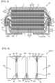
- FIG. 1 is a schematic perspective view of a sealed battery according to the present embodiment
- FIG. 2 is a schematic sectional view of the sealed battery along a broken line X-X in FIG. 1
- FIG. 3 is a schematic sectional view of the sealed battery according to the present embodiment, and corresponds to the schematic sectional view of the sealed battery along the broken line X-X in FIG. 1.
- FIG. 2 illustrates the sealed battery in which a conduction section and an outer surface of a case are in contact with each other directly
- FIG. 3 illustrates the sealed battery in which the conduction section and the outer surface of the case are in contact with each other indirectly with an intermediate layer interposed therebetween.
- FIG. 4 is a schematic top view of an assembled battery or a battery for engine starting according to the present embodiment.
- a sealed battery 40 according to the present embodiment is characterized by including: an electrode assembly 6 including a positive electrode 3, a negative electrode 4, and a separator 5; an electrolyte 7; a case 1 housing the electrode assembly 6 and the electrolyte 7; a first lead terminal 8; and a second lead terminal 9, wherein the first lead terminal 8 and the second lead terminal 9 respectively includes electrode connection sections 11 and 12 which are connected to the positive electrode 3 or the negative electrode 4 inside the case 1, external connection sections 14 and 15 positioned outside the case 1, and sealing sections 17 and 18 to which the case 1 is bonded via adhesive layers 32 and 33, the first lead terminal 8 or the second lead terminal 9 includes conduction section 20 or 21 serving as a conduction path between the sealing section 17 or 18 and the external connection section 14 or 15; the conduction sections 20 and 21 are provided to be at least partially in contact with the outer surface of the case 1 directly or provided to be at least partially in contact with the outer surface of the case 1 indirectly via an intermediate layer 35, the case 1 has a thermal conductivity or an apparent thermal conductivity of from 10
- An assembled battery 50 or a battery 51 for engine starting according to the present embodiment is characterized by including a plurality of the sealed batteries 40 according to the present embodiment, wherein the external connection section 14 included in the first sealed battery 40 and the external connection section 15 included in the second sealed battery 40 are electrically connected to each other.
- the sealed battery, the assembled battery, and the battery for engine starting according to the present embodiment will now be described.
- the sealed battery 40 according to the present embodiment has a sealed structure in which the electrolyte is completely sealed from the outside air so as to prevent leakage during energy storage or during discharge.
- the sealed battery 40 according to the present embodiment may be a secondary battery or a non-aqueous electrolyte secondary battery.
- Examples of the sealed battery 40 according to the present embodiment include lithium-ion batteries, lead-acid batteries, nickel-hydrogen batteries, and nickel-cadmium batteries.
- the assembled battery 50 according to the present embodiment or the battery 51 for engine starting according to the present embodiment may be constituted by a plurality of sealed batteries 40.
- the assembled battery 50 and the battery 51 for engine starting can be formed by connecting a plurality of sealed batteries 40a to 40d in series as in the assembled battery 50 (battery 51 for engine starting) shown in FIG. 4 .
- the case 1 is a casing that houses the electrode assembly 6 including the positive electrode 3, the negative electrode 4, and the separator 5, and the electrolyte 7.
- the material of the case 1 is, for example, a laminate film, plastic, or metal.
- the case 1 can be formed to have a closed space for housing the electrode assembly 6 and the electrolyte 7 therein.
- the sealed battery 40 according to the present embodiment is a pouch battery.
- the case 1 has, on its peripheral edge, a weld part 30 on which the laminate film is overlaid and welded.
- the laminate film is formed by laminating a resin film on both surfaces of a metal film.
- the thickness of the laminate film is, for example, 50 to 200 ⁇ m.
- the electrode assembly 6 includes the positive electrode 3, the negative electrode 4, and the separator 5.
- the electrode assembly 6 may have a stacked structure in which the positive electrode 3 and the negative electrode 4 arranged with the separator 5 therebetween are stacked, or may have a wound structure in which the positive electrode 3 and the negative electrode 4 are wound with the separator 5 therebetween.
- the electrode assembly 6 may include a single separator 5 folded in a zigzag fashion, and the positive electrode 3 and the negative electrode 4 which are disposed in valley folds of the separator 5 and which are alternately disposed with the separator 5 therebetween.
- the number of the positive electrodes 3 and the negative electrodes 4 included in the single electrode assembly 6 may be set, as appropriate, according to the required battery capacity.
- the sealed battery 40 may have a plurality of electrode assemblies 6.
- the separator 5 has a sheet shape and is interposed between the positive electrode 3 and the negative electrode 4.
- the separator 5 is not particularly limited, as long as it can prevent flow of short-circuit current between the positive electrode 3 and the negative electrode 4 and allow the electrolyte to pass therethrough.
- Examples of the separator 5 include a microporous film made of polyolefin or polyethylene.
- the positive electrode 3 can be configured to include a positive-electrode current collector 24 and a positive-electrode active material layer 23 formed on the positive-electrode current collector 24.
- the positive electrode 3 can be manufactured by forming the positive-electrode active material layer 23 on both surfaces of the rectangular positive-electrode current collector 24.
- the positive electrode 3 may have a sheet shape.
- the positive electrode 3 can include a terminal connection section to be connected to the first electrode connection section 11 of the first lead terminal 8.
- the terminal connection section can be formed in such a way that the positive-electrode active material layer 23 is not formed on both surfaces of the positive-electrode current collector 24 at the end of the positive electrode 3.
- the terminal connection section can be formed in such a way that a projecting tab is formed on one end of the positive-electrode current collector 24 so as to project outward therefrom, and the positive-electrode active material layer 23 is not formed on the tab.
- the positive-electrode current collector 24 is not particularly limited, as long as it has electric conductivity and is provided with the positive-electrode active material layer 23 on the surface.
- the positive-electrode current collector 24 is a metal foil, and preferably, an aluminum foil.
- the thickness of the positive-electrode current collector 24 is 100 ⁇ m to 400 ⁇ m, for example.
- the positive-electrode active material layer 23 can be formed on the positive-electrode current collector 24 in such a way that a conductive agent and a binder are added to a positive-electrode active material, and the resultant is coated with a coating method.
- the positive-electrode active material is, for example, a lithium transition metal composite oxide capable of reversibly intercalation and deintercalation of lithium ions.
- the negative electrode 4 can be configured to include a negative-electrode current collector 27 and a negative-electrode active material layer 26 formed on the negative-electrode current collector 27.
- the negative electrode 4 can be manufactured by forming the negative-electrode active material layer 26 on both surfaces of the rectangular negative-electrode current collector 27.
- the negative electrode 4 may have a sheet shape.
- the negative electrode 4 can include a terminal connection section to be connected to the second electrode connection section 12 of the second lead terminal 9.
- the terminal connection section can be formed in such a way that the negative-electrode active material layer 26 is not formed on both surfaces of the negative-electrode current collector 27 at the end of the negative electrode 4.
- the terminal connection section can be formed in such a way that a tab is formed on one end of the negative-electrode current collector 27, and the negative-electrode active material layer 26 is not formed on the tab.
- the negative-electrode current collector 27 is not particularly limited, as long as it has electric conductivity and is provided with the negative-electrode active material layer 26 on the surface.
- the negative-electrode current collector 27 is a metal foil, and preferably, a copper foil.
- the thickness of the negative-electrode current collector 27 is 100 ⁇ m to 400 ⁇ m, for example.
- the negative-electrode active material layer 26 can be formed on the negative-electrode current collector 27 in such a way that a conductive agent and a binder are added to a negative-electrode active material, and the resultant is coated with a coating method.
- examples of the negative-electrode active material include graphite, partially graphitized carbon, hard carbon, soft carbon, LiTiO 4 , and Sn alloy. These materials can be used singly, or two or more kinds can be used as a mixture.
- the solvent used in the electrolyte 7 examples include carbonates, lactones, ethers, and esters. Two or more kinds of these solvents can be used as a mixture. Among these solvents, a mixture of a cyclic carbonate and a chain carbonate is particularly preferable.
- the electrolyte 7 is a solution prepared by, for example, dissolving a lithium salt solute such as LiCF 3 SO 3 , LiAsF 6 , LiClO 4 , LiBF 4 , LiPF 6 , LiBOB, LiN(CF 3 SO 2 ) 2 , or LiN(C 2 F 5 SO 2 ) in an organic solvent.
- the electrolyte 7 may be blended with, as required, one or more types of additives such as VC (vinylene carbonate), PS (propane sultone), VEC (vinyl ethylene carbonate), PRS (propene sultone), and a flame retardant.
- VC vinyl carbonate
- PS propane sultone
- VEC vinyl ethylene carbonate
- PRS propene sultone
- the first lead terminal 8 has the first electrode connection section 11 to be connected to the positive electrode 3 inside the case 1, the first external connection section 14 positioned outside the case 1, and the first sealing section 17 bonded to the case 1 via the first adhesive layer 32.
- the second lead terminal 9 has the second electrode connection section 12 to be connected to the negative electrode 4 inside the case 1, the second external connection section 15 positioned outside the case 1, and the second sealing section 18 bonded to the case 1 via the second adhesive layer 33. Due to the first lead terminal 8 and the second lead terminal 9 configured as described above being provided, a terminal voltage can be generated between the first external connection section 14 and the second external connection section 15, and electric power can be supplied to devices or vehicles.
- the sealed battery 40 can be charged by applying a voltage between the first external connection section 14 and the second external connection section 15.
- the first electrode connection section 11 indicates an area where the positive-electrode current collector 24 is welded to the first lead terminal 8.
- the second electrode connection section 12 indicates an area where the negative-electrode current collector 27 is welded to the second lead terminal 9.
- the external connection sections 14 and 15 are connected to external wirings.
- the external connection sections 14 and 15 may be connected to wiring terminals, external connection sections of other batteries, or a battery connection terminal 37 of a device.
- an external connection section 15a of the sealed battery 40a may be connected to an external connection section 14b of the sealed battery 40b.
- An external connection section 15d of the sealed battery 40d may be connected to a battery connection terminal 37b of a device.
- the first sealing section 17 indicates an area where the first lead terminal 8 is bonded to the case 1 using the first adhesive layer 32.
- the second sealing section 18 indicates an area where the second lead terminal 9 is bonded to the case 1 using the second adhesive layer 33. Due to the adhesive layers 32 and 33 being interposed between the lead terminals 8 and 9 and the case 1, the gap between the lead terminals 8 and 9 and the case 1 can be filled, whereby the performance of sealing the interior of the case 1 can be improved.
- the sealing sections 17 and 18 can be provided on the peripheral edge of the case 1.
- the adhesive layers 32 and 33 may be a bonding tape or an adhesive agent layer.
- the lead terminals 8 and 9 are formed of a metal plate having a thickness of 100 ⁇ m to 500 ⁇ m.
- the metal plate may be pressed or bent.
- the surface of the metal plate may be treated with plating or the like.
- the first lead terminal 8 is an aluminum plate
- the second lead terminal 9 is a copper plate.
- the lead terminals 8 and 9 may have a rectangular shape or an L shape, for example.
- the lead terminals 8 and 9 may have tabs serving as the external connection sections 14 and 15.
- the lead terminals 8 and 9 may be formed by processing a single metal plate.
- the first lead terminal 8 has a first conduction section 20 serving as a conduction path between the first sealing section 17 and the first external connection section 14.
- the second lead terminal 9 has a second conduction section 21 serving as a conduction path between the second sealing section 18 and the second external connection section 15.
- the formation of the conduction sections 20 and 21 makes it possible to provide the external connection sections 14 and 15 at positions distant from the sealing sections 17 and 18, and this enables the sealed battery 40 to be used for various types of devices. Note that it is only sufficient that the conduction section is provided on at least either the first lead terminal 8 or the second lead terminal 9.
- the conduction sections 20 and 21 are provided to occupy 50% or more, 60% or more, 70% or more, or 80% or more of the lead terminals 8 and 9. This makes it possible to provide the external connection sections 14 and 15 at positions distant from the sealing sections 17 and 18.
- the conduction sections 20 and 21 are provided to be at least partially in contact with the outer surface of the case 1 directly, or provided to be at least partially in contact with the outer surface of the case 1 indirectly with the intermediate layer 35 therebetween. For this reason, even if the sealed battery 40 is discharged with a large current and the first or the second lead terminal generates heat, the heat generated from the lead terminal 8 or 9 can be dissipated to the case 1.
- the conduction sections 20 and 21 can be provided, for example, to be in direct contact with the outer surface of the case 1 as in the sealed battery 40 shown in FIGS. 1 and 2 . Thus, the heat from the lead terminals 8 and 9 can be directly dissipated to the case 1.
- the conduction sections 20 and 21 can be provided, for example, to in contact with the outer surface of the case 1 indirectly with the intermediate layer 35 therebetween as in the sealed battery 40 shown in FIG. 3 .
- the intermediate layer 35 can be provided to be in direct contact with the outer surface of the case, and to be in direct contact with the conduction sections 20 and 21.
- the intermediate layer 35 may be a grease layer.
- the formation of the grease layer between the conduction sections 20 and 21 and the outer surface of the case 1 makes it possible to increase the contact area between the conduction section 20 and the grease layer and the contact area between the grease layer and the outer surface of the case 1.
- the grease layer is preferably a thermal conductive grease layer.
- Examples of the grease layer include the one obtained by mixing, into grease, metal oxide powders such as alumina or zinc oxide, inorganic particles such as diamond, silica, or silicon carbide, or metal powders such as silver or aluminum.
- the intermediate layer 35 may be an insulator layer.
- the insulator layer is interposed between the conduction sections 20 and 21 and the outer surface of the case 1, the flow of leak current can be prevented even if the outer surface of the case 1 is conductive.
- a material by which the apparent thermal conductivity of 10 W/(m ⁇ K) or higher of the case 1 including the intermediate layer 35 is achieved is selected for the intermediate layer 35.
- the conduction sections 20 and 21 can be provided such that 60% or more of the conduction sections 20 and 21 are in contact with the outer surface of the case 1 directly or indirectly. This makes it possible to prevent a temperature rise in areas of the conduction sections 20 and 21 not in contact with the outer surface of the case 1 directly or indirectly.
- the conduction sections 20 and 21 can be provided such that 65% or more, 70% or more, 75% or more, or 80% or more of the conduction sections 20 and 21 are in contact with the outer surface of the case 1 directly or indirectly.
- the lead terminals 8 and 9 may contact the outer surface of the case 1 or the intermediate layer 35 at a position where the length of the lead terminals from the electrode connection side end is 1.5 times or less the thickness of the sealed battery 40.
- the conduction sections 20 and 21 can be provided on the electrode assembly 6 so as to at least partially overlap the electrode assembly 6 via the case 1.
- the conduction sections 20 and 21 which are substantially flat can be directly or indirectly in contact with the outer surface of the case 1 which is substantially flat, whereby heat from the lead terminals 8 and 9 can be efficiently dissipated to the case 1.
- the electrode assembly 6 can be configured to have a stacked structure.
- the electrode assembly 6 can be positioned between the first sealing section 17 and the second sealing section 18. With this configuration, the first lead terminal 8 can be leaded out from one end of the case 1, and the second lead terminal 9 can be leaded out from the other end. Thus, even when both of the first conduction section 20 and the second conduction section 21 are brought into contact with the outer surface of the case 1 directly or indirectly, a decrease in the space between the first lead terminal 8 and the second lead terminal 9 can be prevented, and the flow of leak current can be prevented. In addition, heat from the first lead terminal 8 and the second lead terminal 9 can be uniformly distributed to the electrode assembly 6 and the electrolyte 7.
- the first conduction section 20 can be brought into contact with one side of the case 1 directly or indirectly, and the second conduction section 21 can be brought into contact with the opposite side of the case 1 directly or indirectly.
- the electrode assembly 6 can be interposed between the first conduction section 20 and the second conduction section 21, whereby an increase in the temperature of the lead terminals 8 and 9 can be prevented.
- At least a part of the conduction sections 20 and 21 included in the first sealed battery 40 may be directly in contact with the outer surface of the case 1 included in the second sealed battery 40.
- at least a part of the conduction sections 20 and 21 included in the first sealed battery 40 may be indirectly in contact with the outer surface of the case 1 included in the second sealed battery 40 with the intermediate layer 35 therebetween.
- a conduction section of a lead terminal 9d of the sealed battery 40d included in the assembled battery 50 (battery 51 for engine starting) shown in FIG. 4 can be provided to be directly or indirectly in contact with the outer surface of the case 1 of the adjacent sealed battery 40c. Further, at least a part of the conduction sections 20 and 21 included in the first sealed battery 40 may be sandwiched between the first sealed battery 40 and the second sealed battery 40.
- the case 1 has a thermal conductivity or apparent thermal conductivity of from 10 W/(m ⁇ K) to 250 W/(m ⁇ K) inclusive.
- the case 1 can transmit heat, and the heat from the lead terminals 8 and 9 can be dissipated to the case 1, the electrolyte 7, the electrode assembly 6, or the like.
- the case 1 may have a thermal conductivity or apparent thermal conductivity of from 10 W/(m ⁇ K) to 250 W/(m ⁇ K) inclusive in the thickness direction.
- the case 1 may have a thermal conductivity or apparent thermal conductivity of from 10 W/(m ⁇ K) to 100 W/(m ⁇ K) inclusive.
- the thermal conductivity or the apparent thermal conductivity may be obtained by a laser flash method. According to the result and calculation by simulation, it is found that the thermal conductivity or apparent thermal conductivity of 10 W/(m ⁇ K) or more is sufficient.
- one of the main surfaces of a plate-shaped sample constituting the case 1 is irradiated with a laser beam and instantaneously heated, and the thermal diffusivity and thermal conductivity can be calculated on the basis of an increase in the temperature of the back surface opposite to the surface irradiated with the laser beam.
- the thermal conductivity is calculated, and when the case 1 is formed from a composite material, the apparent thermal conductivity is calculated.
- the electrode assembly 6 and the electrolyte 7 housed in the case 1 have an effective thermal conductivity of from 10 W/(m ⁇ K) to 100 W/(m ⁇ K) inclusive in a steady state.
- the heat dissipated from the conduction sections 20 and 21 to the case 1 can be transmitted to the entire electrode assembly 6 and the entire electrolyte 7. This can prevent a local temperature increase in the conduction sections 20 and 21, the case 1, the electrode assembly 6, and the electrolyte 7.
- the effective thermal conductivity of the electrode assembly 6 and the electrolyte 7 is measured while they are housed in the case 1, and calculated from the measurement result.
- the effective thermal conductivity is calculated with the electrode assembly 6 and the electrolyte 7 being regarded as an integrated unit, not with the electrode assembly 6 and the electrolyte 7 being treated as an individual member.
- the effective thermal conductivity in the steady state is calculated in such a manner that, for example, one of the outer surfaces of the case 1 included in the sealed battery 40 is heated with a hot plate, the opposite outer surface of the case 1 is cooled to a normal temperature, and the temperature gradient inside the sealed battery 40 in the steady state is measured.
- the effective thermal conductivity is calculated according to simulation in consideration of the result of the case, it is found that the effective thermal conductivity of 10 W/(m ⁇ K) is sufficient.
- the effective thermal conductivity of the electrode assembly 6 and the electrolyte 7 housed in the case 1 in the steady state may be equal to or greater than the thermal conductivity or the apparent thermal conductivity of the case 1.
- the heat of the case 1 can be quickly transmitted to the electrode assembly 6 and the electrolyte 7. Accordingly, even when the heat dissipation time is increased, the separator 5 is prevented from being damaged by heat accumulated in the case 1.
- the heat capacity per 1 g of a sum total of the case 1, the electrode assembly 6, and the electrolyte 7 is 0.5 J/(g ⁇ K) to 2.0 J/(g ⁇ K). This can increase an amount of heat which can be dissipated to the case 1, the electrode assembly 6, and the electrolyte 7 by the conduction sections 20 and 21, whereby an increase in the temperature of the lead terminals 8 and 9 can be prevented. Accordingly, the adhesive layers 32 and 33 of the sealing sections 17 and 18 can be prevented from being melted by the heat of the lead terminals 8 and 9, and this can prevent deterioration of the performance of sealing the interior of the case 1.
- a paste was prepared using lithium iron phosphate powders used as a positive-electrode active material, acetylene black used as a conductive auxiliary agent, and polyvinylidene fluoride (PVdF) used as a binder.
- the prepared paste was coated on both surfaces of an aluminum foil serving as a positive-electrode current collector and dried.
- a positive electrode provided with positive-electrode active material layers on both surfaces of the aluminum foil was manufactured.
- a paste was prepared using soft carbon used as a negative-electrode active material, styrene-butadiene copolymer (SBR) used as a binder, and carboxymethylcellulose (CMC) used as a thickener.
- SBR styrene-butadiene copolymer
- CMC carboxymethylcellulose
- a separator made of a polyethylene material, and thirty-one negative electrodes were stacked so that the adjacent positive-electrode active material layer and the negative-electrode active material layer face each other with the separator therebetween, and the positive electrodes and the negative electrodes were singly covered by the separator.
- the positive-electrode current collectors included in the thirty positive electrodes were welded to a first lead terminal, and the negative-electrode current collectors included in the thirty-one negative electrodes were welded to a second lead terminal.
- FIG. 5(a) with a thickness of 200 ⁇ m was used for the first lead terminal, and a copper plate having a size as shown in FIG. 5(a) with a thickness of 200 ⁇ m was used for the second lead terminal.
- the electrode assembly was covered by a laminate film, and the peripheral edge of the laminate film was welded to form a case.
- An adhesive layer was provided between the laminate film and the lead terminals, and the lead terminals and the adhesive layer were welded to the laminate film.
- a test battery according to Comparative Example was manufactured by changing the material of the laminate film.
- the test battery was manufactured in the same manner as the test battery according to Working Example except that the material of the laminate film was changed.
- the laminate film was formed by laminating a polyethylene terephthalate layer on an outer side of a stainless steel layer and a polyethylene layer on an inner side of the stainless steel layer.
- the thermal conductivities of the laminate films used for manufacturing the test batteries were measured with a laser flash method.
- the thermal conductivity of the laminate film used for manufacturing the test battery according to Working Example in the thickness direction was about 17 W/(m ⁇ K).
- the thermal conductivity of the laminate film used for manufacturing the test battery according to Comparative Example in the thickness direction was about 9.2 W/(m ⁇ K).
- the thermal conductivity of the electrode assembly and the electrolyte included in the test battery according to Working Example was measured using a steady method. Specifically, one of the outer surfaces of the case included in the test battery according to Working Example was heated with a hot plate, and the opposite outer surface of the case was air-cooled. The temperature between the hot plate and the outer surface of the case, the temperature between the inner surface of the case and the electrode assembly, and the temperature of the air-cooled outer surface of the case were measured in a steady state to obtain a temperature gradient. The thermal conductivity of the electrode assembly and the electrolyte was calculated on the basis of the obtained temperature gradient. The thermal conductivity of the electrode assembly and the electrolyte was about 17.9 W/(m ⁇ K).
- the heat capacity per 1 g of a sum total of the case, the electrode assembly, and the electrolyte was calculated on the basis of the specific heat, density, and mass of the material used for manufacturing the test battery according to Working Example.
- the calculated heat capacity was 0.921 J/(g ⁇ K).
- a DC current of 150 A was applied to aluminum plates (samples (b) to (f)) similar to the first lead terminal used for manufacturing the test battery according to Working Example for 240 seconds in a constant temperature chamber at 25°C, and the temperature of each of the aluminum plates was measured.
- the value of 150 A is the highest current value in lead-acid batteries for motorcycles in Japanese Industrial Standards (JISD 5302-2004).
- the lead terminals were bent so that one side of the first and second conduction sections of the test battery according to Working Example was in contact with the outer surface of the case, and the conduction sections were fixed to the outer surface of the case with an insulating tape.
- the lead terminals were bent so that about 60% of the area of the lead terminals was in contact with the outer surface of the case.
- the test battery according to Working Example was discharged for about 240 seconds so that about 150 A of current flew through the lead terminals.
- the lead terminals were bent so that one side of the first and second conduction sections of the test battery according to Comparative Example was in contact with the outer surface of the case, and the conduction sections were fixed to the outer surface of the case with an insulating tape.
- the lead terminals were bent so that about 60% of the area of the lead terminals was in contact with the outer surface of the case.
- the test battery according to Comparative Example was discharged for about 240 seconds so that about 150 A of current flew through the lead terminals.
Landscapes
- Chemical & Material Sciences (AREA)
- Chemical Kinetics & Catalysis (AREA)
- General Chemical & Material Sciences (AREA)
- Electrochemistry (AREA)
- Engineering & Computer Science (AREA)
- Manufacturing & Machinery (AREA)
- General Engineering & Computer Science (AREA)
- Mechanical Engineering (AREA)
- Combustion & Propulsion (AREA)
- Physics & Mathematics (AREA)
- Algebra (AREA)
- General Physics & Mathematics (AREA)
- Mathematical Analysis (AREA)
- Mathematical Optimization (AREA)
- Pure & Applied Mathematics (AREA)
- Sealing Battery Cases Or Jackets (AREA)
- Connection Of Batteries Or Terminals (AREA)
- Secondary Cells (AREA)
- Battery Mounting, Suspending (AREA)
Description
- The present invention relates to a sealed battery, an assembled battery, and a battery for engine starting.
- A pouch battery including a positive electrode, a negative electrode, a separator, and an electrolyte which are housed inside a case made of a laminate film have been put into practical use. In the pouch battery, a part of a lead terminal is positioned inside the case and connected to the positive electrode or the negative electrode, and a part of the lead terminal is positioned outside of the case and connected to an external wiring. The laminate film is bonded to the lead terminal on the peripheral end of the case for sealing the interior of the case. Further, in order to improve performance of sealing the interior of the case, a terminal bonding tape is interposed between the laminate film and the lead terminal (for example, see Patent Document 1). When the laminate film is heat-sealed, the bonding tape is melted and fills a gap between the laminate film and the lead terminal.
- Meanwhile, a battery for engine starting is mounted on a vehicle or a motorcycle. Large power is needed to start the engine, and thus, the battery needs to output large power in a short period of time (for example, see Patent Document 2).
-
- Patent Document 1:
WO 2012/020721 A1 - Patent Document 2:
JP 05-202834 A - When the pouch battery is used for a battery for engine starting, a large current flows through the lead terminal upon start of the engine, and the lead terminal generates heat. Due to the generated heat, a terminal bonding portion is melted, which may deteriorate sealing performance of the battery.
- The present invention is accomplished in view of the above circumstance, and provides a sealed battery capable of preventing from a decrease in sealing performance of the battery.
- The present invention provides a sealed battery as defined in
claim 1, an assembled battery as defined inclaim 8 and a battery for engine starting as defined in claim 10, preferred embodiments are defined in dependent claims 2-7 and 9. - The sealed battery according to the present invention includes: an electrode assembly including a positive electrode, a negative electrode, and a separator; an electrolyte; a case which houses the electrode assembly and the electrolyte; a first lead terminal; and a second lead terminal, and each of the first lead terminal and the second lead terminal includes an electrode connection section which is connected to the positive electrode or the negative electrode inside the case, and an external connection section positioned outside the case. Thus, a terminal voltage can be generated between the external connection section of the first lead terminal and the external connection section of the second lead terminal, and electric power can be supplied to devices or vehicles.
- Each of the first and second lead terminals includes a sealing section to which the case is bonded via an adhesive layer. Thus, the performance of sealing the interior of the case can be improved, whereby leakage of the electrolyte in the case can be prevented.
- The first or the second lead terminal includes a conduction section serving as a conduction path between the sealing section and the external connection section. This makes it possible to provide the external connection section at a position distant from the sealing section, and thus, the sealed battery according to the present invention can be used for various types of devices.
- The conduction section is provided to be at least partially in contact with the outer surface of the case directly, or provided to be at least partially in contact with the outer surface of the case indirectly via the intermediate layer. Thus, even if the sealed battery is discharged with a large current and the first or second lead terminal generates heat, the heat from the lead terminal can be dissipated to the case.
- The case has a conductivity or an apparent thermal conductivity of from 10 W/(m·K) to 250 W/(m·K) inclusive, and the electrode assembly and the electrolyte contained in the case have an effective thermal conductivity of from 10 W/(m·K) to 100 W/(m·K) inclusive in a steady state. Thus, heat from the lead terminal can be dissipated to the electrode assembly and the electrolyte via the case, whereby an increase in the temperature of the first or second lead terminal can be prevented. This results in preventing the adhesive layer at the sealing section from being melted, whereby deterioration in sealing performance of the battery can be suppressed.
-
-
FIG. 1 is a schematic perspective view of a sealed battery according to one embodiment of the present invention. -
FIG. 2 is a schematic sectional view of the sealed battery along a broken line X-X inFIG. 1 . -
FIG. 3 is a schematic sectional view of the sealed battery according to one embodiment of the present invention. -
FIG. 4 is a schematic top view of an assembled battery or a battery for engine starting according to one embodiment of the present invention. -
FIGS. 5(a) to 5(f) are explanatory views of a lead terminal used in a conduction experiment. -
FIG. 6 is a graph showing the result of the conduction experiment. - One embodiment of the present invention will now be described with reference to the drawings. The configurations shown in the drawings and the following description are merely illustrative, and the scope of the present invention is not limited thereto.
-
FIG. 1 is a schematic perspective view of a sealed battery according to the present embodiment, andFIG. 2 is a schematic sectional view of the sealed battery along a broken line X-X inFIG. 1 .FIG. 3 is a schematic sectional view of the sealed battery according to the present embodiment, and corresponds to the schematic sectional view of the sealed battery along the broken line X-X inFIG. 1. FIG. 2 illustrates the sealed battery in which a conduction section and an outer surface of a case are in contact with each other directly, andFIG. 3 illustrates the sealed battery in which the conduction section and the outer surface of the case are in contact with each other indirectly with an intermediate layer interposed therebetween.FIG. 4 is a schematic top view of an assembled battery or a battery for engine starting according to the present embodiment. - A sealed
battery 40 according to the present embodiment is characterized by including: an electrode assembly 6 including apositive electrode 3, anegative electrode 4, and aseparator 5; anelectrolyte 7; acase 1 housing the electrode assembly 6 and theelectrolyte 7; afirst lead terminal 8; and asecond lead terminal 9, wherein thefirst lead terminal 8 and thesecond lead terminal 9 respectively includeselectrode connection sections positive electrode 3 or thenegative electrode 4 inside thecase 1,external connection sections case 1, and sealingsections case 1 is bonded viaadhesive layers first lead terminal 8 or thesecond lead terminal 9 includesconduction section sealing section external connection section conduction sections case 1 directly or provided to be at least partially in contact with the outer surface of thecase 1 indirectly via an intermediate layer 35, thecase 1 has a thermal conductivity or an apparent thermal conductivity of from 10 W/(m·K) to 250 W/(m·K) inclusive, and the electrode assembly 6 and theelectrolyte 7 contained in thecase 1 have an effective thermal conductivity of from 10 W/(m·K) to 100 W/(m·K) inclusive in a steady state. - An assembled
battery 50 or abattery 51 for engine starting according to the present embodiment is characterized by including a plurality of the sealedbatteries 40 according to the present embodiment, wherein theexternal connection section 14 included in the first sealedbattery 40 and theexternal connection section 15 included in the second sealedbattery 40 are electrically connected to each other. - The sealed battery, the assembled battery, and the battery for engine starting according to the present embodiment will now be described.
- The sealed
battery 40 according to the present embodiment has a sealed structure in which the electrolyte is completely sealed from the outside air so as to prevent leakage during energy storage or during discharge. The sealedbattery 40 according to the present embodiment may be a secondary battery or a non-aqueous electrolyte secondary battery. Examples of the sealedbattery 40 according to the present embodiment include lithium-ion batteries, lead-acid batteries, nickel-hydrogen batteries, and nickel-cadmium batteries. - The assembled
battery 50 according to the present embodiment or thebattery 51 for engine starting according to the present embodiment may be constituted by a plurality of sealedbatteries 40. For example, the assembledbattery 50 and thebattery 51 for engine starting can be formed by connecting a plurality of sealedbatteries 40a to 40d in series as in the assembled battery 50 (battery 51 for engine starting) shown inFIG. 4 . - The
case 1 is a casing that houses the electrode assembly 6 including thepositive electrode 3, thenegative electrode 4, and theseparator 5, and theelectrolyte 7. The material of thecase 1 is, for example, a laminate film, plastic, or metal. Thecase 1 can be formed to have a closed space for housing the electrode assembly 6 and theelectrolyte 7 therein. If the material of thecase 1 is a laminate film, the sealedbattery 40 according to the present embodiment is a pouch battery. In this case, thecase 1 has, on its peripheral edge, aweld part 30 on which the laminate film is overlaid and welded. The laminate film is formed by laminating a resin film on both surfaces of a metal film. The thickness of the laminate film is, for example, 50 to 200 µm. - The electrode assembly 6 includes the
positive electrode 3, thenegative electrode 4, and theseparator 5. The electrode assembly 6 may have a stacked structure in which thepositive electrode 3 and thenegative electrode 4 arranged with theseparator 5 therebetween are stacked, or may have a wound structure in which thepositive electrode 3 and thenegative electrode 4 are wound with theseparator 5 therebetween. For example, the electrode assembly 6 may include asingle separator 5 folded in a zigzag fashion, and thepositive electrode 3 and thenegative electrode 4 which are disposed in valley folds of theseparator 5 and which are alternately disposed with theseparator 5 therebetween. The number of thepositive electrodes 3 and thenegative electrodes 4 included in the single electrode assembly 6 may be set, as appropriate, according to the required battery capacity. The sealedbattery 40 may have a plurality of electrode assemblies 6. - The
separator 5 has a sheet shape and is interposed between thepositive electrode 3 and thenegative electrode 4. Theseparator 5 is not particularly limited, as long as it can prevent flow of short-circuit current between thepositive electrode 3 and thenegative electrode 4 and allow the electrolyte to pass therethrough. Examples of theseparator 5 include a microporous film made of polyolefin or polyethylene. - The
positive electrode 3 can be configured to include a positive-electrodecurrent collector 24 and a positive-electrodeactive material layer 23 formed on the positive-electrodecurrent collector 24. Thepositive electrode 3 can be manufactured by forming the positive-electrodeactive material layer 23 on both surfaces of the rectangular positive-electrodecurrent collector 24. Thepositive electrode 3 may have a sheet shape. Thepositive electrode 3 can include a terminal connection section to be connected to the firstelectrode connection section 11 of thefirst lead terminal 8. The terminal connection section can be formed in such a way that the positive-electrodeactive material layer 23 is not formed on both surfaces of the positive-electrodecurrent collector 24 at the end of thepositive electrode 3. Alternatively, the terminal connection section can be formed in such a way that a projecting tab is formed on one end of the positive-electrodecurrent collector 24 so as to project outward therefrom, and the positive-electrodeactive material layer 23 is not formed on the tab. - The positive-electrode
current collector 24 is not particularly limited, as long as it has electric conductivity and is provided with the positive-electrodeactive material layer 23 on the surface. For example, the positive-electrodecurrent collector 24 is a metal foil, and preferably, an aluminum foil. The thickness of the positive-electrodecurrent collector 24 is 100 µm to 400 µm, for example. - The positive-electrode
active material layer 23 can be formed on the positive-electrodecurrent collector 24 in such a way that a conductive agent and a binder are added to a positive-electrode active material, and the resultant is coated with a coating method. The positive-electrode active material is, for example, a lithium transition metal composite oxide capable of reversibly intercalation and deintercalation of lithium ions. Specific examples of the positive-electrode active material include LiCoO2, LiNiO2, LiNixCo1-xO2 (x=0.01-0.99), LiMnO2, LiMn2O4, LiCoxMnyNizO2 (x+y+z=1), and olivine-type LiFePO4 and LixFe1-yMyPO4 (wherein: 0.05≦x≦ 1.2 and 0≦y ≦0.8; and M is at least one of Mn, Cr, Co, Cu, Ni, V, Mo, Ti, Zn, Al, Ga, Mg, B, and Nb). These materials can be used singly, or two or more kinds can be used as a mixture. - The
negative electrode 4 can be configured to include a negative-electrodecurrent collector 27 and a negative-electrodeactive material layer 26 formed on the negative-electrodecurrent collector 27. Thenegative electrode 4 can be manufactured by forming the negative-electrodeactive material layer 26 on both surfaces of the rectangular negative-electrodecurrent collector 27. Thenegative electrode 4 may have a sheet shape. Thenegative electrode 4 can include a terminal connection section to be connected to the secondelectrode connection section 12 of thesecond lead terminal 9. The terminal connection section can be formed in such a way that the negative-electrodeactive material layer 26 is not formed on both surfaces of the negative-electrodecurrent collector 27 at the end of thenegative electrode 4. Alternatively, the terminal connection section can be formed in such a way that a tab is formed on one end of the negative-electrodecurrent collector 27, and the negative-electrodeactive material layer 26 is not formed on the tab. - The negative-electrode
current collector 27 is not particularly limited, as long as it has electric conductivity and is provided with the negative-electrodeactive material layer 26 on the surface. For example, the negative-electrodecurrent collector 27 is a metal foil, and preferably, a copper foil. The thickness of the negative-electrodecurrent collector 27 is 100 µm to 400 µm, for example. - The negative-electrode
active material layer 26 can be formed on the negative-electrodecurrent collector 27 in such a way that a conductive agent and a binder are added to a negative-electrode active material, and the resultant is coated with a coating method. When the sealed battery is a lithium ion secondary battery, examples of the negative-electrode active material include graphite, partially graphitized carbon, hard carbon, soft carbon, LiTiO4, and Sn alloy. These materials can be used singly, or two or more kinds can be used as a mixture. - Examples of the solvent used in the
electrolyte 7 include carbonates, lactones, ethers, and esters. Two or more kinds of these solvents can be used as a mixture. Among these solvents, a mixture of a cyclic carbonate and a chain carbonate is particularly preferable. Theelectrolyte 7 is a solution prepared by, for example, dissolving a lithium salt solute such as LiCF3SO3, LiAsF6, LiClO4, LiBF4, LiPF6, LiBOB, LiN(CF3SO2)2, or LiN(C2F5SO2) in an organic solvent. Theelectrolyte 7 may be blended with, as required, one or more types of additives such as VC (vinylene carbonate), PS (propane sultone), VEC (vinyl ethylene carbonate), PRS (propene sultone), and a flame retardant. - The
first lead terminal 8 has the firstelectrode connection section 11 to be connected to thepositive electrode 3 inside thecase 1, the firstexternal connection section 14 positioned outside thecase 1, and thefirst sealing section 17 bonded to thecase 1 via the firstadhesive layer 32. Thesecond lead terminal 9 has the secondelectrode connection section 12 to be connected to thenegative electrode 4 inside thecase 1, the secondexternal connection section 15 positioned outside thecase 1, and thesecond sealing section 18 bonded to thecase 1 via the secondadhesive layer 33. Due to thefirst lead terminal 8 and thesecond lead terminal 9 configured as described above being provided, a terminal voltage can be generated between the firstexternal connection section 14 and the secondexternal connection section 15, and electric power can be supplied to devices or vehicles. The sealedbattery 40 can be charged by applying a voltage between the firstexternal connection section 14 and the secondexternal connection section 15. - The first
electrode connection section 11 indicates an area where the positive-electrodecurrent collector 24 is welded to thefirst lead terminal 8. The secondelectrode connection section 12 indicates an area where the negative-electrodecurrent collector 27 is welded to thesecond lead terminal 9. - The
external connection sections external connection sections - For example, in the assembled battery 50 (
battery 51 for engine starting) shown inFIG. 4 , anexternal connection section 15a of the sealedbattery 40a may be connected to anexternal connection section 14b of the sealedbattery 40b. Anexternal connection section 15d of the sealedbattery 40d may be connected to abattery connection terminal 37b of a device. - The
first sealing section 17 indicates an area where thefirst lead terminal 8 is bonded to thecase 1 using the firstadhesive layer 32. Thesecond sealing section 18 indicates an area where thesecond lead terminal 9 is bonded to thecase 1 using the secondadhesive layer 33. Due to theadhesive layers lead terminals case 1, the gap between thelead terminals case 1 can be filled, whereby the performance of sealing the interior of thecase 1 can be improved. The sealingsections case 1. The adhesive layers 32 and 33 may be a bonding tape or an adhesive agent layer. - The
lead terminals first lead terminal 8 is an aluminum plate, and thesecond lead terminal 9 is a copper plate. Thelead terminals lead terminals external connection sections lead terminals - The
first lead terminal 8 has afirst conduction section 20 serving as a conduction path between thefirst sealing section 17 and the firstexternal connection section 14. Thesecond lead terminal 9 has asecond conduction section 21 serving as a conduction path between thesecond sealing section 18 and the secondexternal connection section 15. The formation of theconduction sections external connection sections sections battery 40 to be used for various types of devices. Note that it is only sufficient that the conduction section is provided on at least either thefirst lead terminal 8 or thesecond lead terminal 9. - The
conduction sections lead terminals external connection sections sections - The
conduction sections case 1 directly, or provided to be at least partially in contact with the outer surface of thecase 1 indirectly with the intermediate layer 35 therebetween. For this reason, even if the sealedbattery 40 is discharged with a large current and the first or the second lead terminal generates heat, the heat generated from thelead terminal case 1. Theconduction sections case 1 as in the sealedbattery 40 shown inFIGS. 1 and 2 . Thus, the heat from thelead terminals case 1. - The
conduction sections case 1 indirectly with the intermediate layer 35 therebetween as in the sealedbattery 40 shown inFIG. 3 . The intermediate layer 35 can be provided to be in direct contact with the outer surface of the case, and to be in direct contact with theconduction sections - The intermediate layer 35 may be a grease layer. The formation of the grease layer between the
conduction sections case 1 makes it possible to increase the contact area between theconduction section 20 and the grease layer and the contact area between the grease layer and the outer surface of thecase 1. Thus, the heat from thelead terminals case 1. The grease layer is preferably a thermal conductive grease layer. Examples of the grease layer include the one obtained by mixing, into grease, metal oxide powders such as alumina or zinc oxide, inorganic particles such as diamond, silica, or silicon carbide, or metal powders such as silver or aluminum. - The intermediate layer 35 may be an insulator layer. When the insulator layer is interposed between the
conduction sections case 1, the flow of leak current can be prevented even if the outer surface of thecase 1 is conductive. - It is preferable that a material by which the apparent thermal conductivity of 10 W/(m·K) or higher of the
case 1 including the intermediate layer 35 is achieved is selected for the intermediate layer 35. - The
conduction sections conduction sections case 1 directly or indirectly. This makes it possible to prevent a temperature rise in areas of theconduction sections case 1 directly or indirectly. Theconduction sections conduction sections case 1 directly or indirectly. - The
lead terminals case 1 or the intermediate layer 35 at a position where the length of the lead terminals from the electrode connection side end is 1.5 times or less the thickness of the sealedbattery 40. - The
conduction sections case 1. Thus, theconduction sections case 1 which is substantially flat, whereby heat from thelead terminals case 1. In this case, the electrode assembly 6 can be configured to have a stacked structure. - The electrode assembly 6 can be positioned between the
first sealing section 17 and thesecond sealing section 18. With this configuration, thefirst lead terminal 8 can be leaded out from one end of thecase 1, and thesecond lead terminal 9 can be leaded out from the other end. Thus, even when both of thefirst conduction section 20 and thesecond conduction section 21 are brought into contact with the outer surface of thecase 1 directly or indirectly, a decrease in the space between thefirst lead terminal 8 and thesecond lead terminal 9 can be prevented, and the flow of leak current can be prevented. In addition, heat from thefirst lead terminal 8 and thesecond lead terminal 9 can be uniformly distributed to the electrode assembly 6 and theelectrolyte 7. - The
first conduction section 20 can be brought into contact with one side of thecase 1 directly or indirectly, and thesecond conduction section 21 can be brought into contact with the opposite side of thecase 1 directly or indirectly. With this configuration, the electrode assembly 6 can be interposed between thefirst conduction section 20 and thesecond conduction section 21, whereby an increase in the temperature of thelead terminals - At least a part of the
conduction sections battery 40 may be directly in contact with the outer surface of thecase 1 included in the second sealedbattery 40. Alternatively, at least a part of theconduction sections battery 40 may be indirectly in contact with the outer surface of thecase 1 included in the second sealedbattery 40 with the intermediate layer 35 therebetween. With this configuration, even if the first sealedbattery 40 is discharged with a large current and thefirst lead terminal 8 or thesecond lead terminal 9 generates heat, the generated heat from thelead terminal case 1 of the second sealedbattery 40. For example, a conduction section of a lead terminal 9d of the sealedbattery 40d included in the assembled battery 50 (battery 51 for engine starting) shown inFIG. 4 can be provided to be directly or indirectly in contact with the outer surface of thecase 1 of the adjacent sealedbattery 40c. Further, at least a part of theconduction sections battery 40 may be sandwiched between the first sealedbattery 40 and the second sealedbattery 40. - The
case 1 has a thermal conductivity or apparent thermal conductivity of from 10 W/(m·K) to 250 W/(m·K) inclusive. Thus, thecase 1 can transmit heat, and the heat from thelead terminals case 1, theelectrolyte 7, the electrode assembly 6, or the like. Thecase 1 may have a thermal conductivity or apparent thermal conductivity of from 10 W/(m·K) to 250 W/(m·K) inclusive in the thickness direction. Thecase 1 may have a thermal conductivity or apparent thermal conductivity of from 10 W/(m·K) to 100 W/(m·K) inclusive. The thermal conductivity or the apparent thermal conductivity may be obtained by a laser flash method. According to the result and calculation by simulation, it is found that the thermal conductivity or apparent thermal conductivity of 10 W/(m·K) or more is sufficient. - In the laser flash method, one of the main surfaces of a plate-shaped sample constituting the
case 1 is irradiated with a laser beam and instantaneously heated, and the thermal diffusivity and thermal conductivity can be calculated on the basis of an increase in the temperature of the back surface opposite to the surface irradiated with the laser beam. When thecase 1 is formed from a single material, the thermal conductivity is calculated, and when thecase 1 is formed from a composite material, the apparent thermal conductivity is calculated. - The electrode assembly 6 and the
electrolyte 7 housed in thecase 1 have an effective thermal conductivity of from 10 W/(m·K) to 100 W/(m·K) inclusive in a steady state. Thus, the heat dissipated from theconduction sections case 1 can be transmitted to the entire electrode assembly 6 and theentire electrolyte 7. This can prevent a local temperature increase in theconduction sections case 1, the electrode assembly 6, and theelectrolyte 7. In the present embodiment, the effective thermal conductivity of the electrode assembly 6 and theelectrolyte 7 is measured while they are housed in thecase 1, and calculated from the measurement result. Therefore, the effective thermal conductivity is calculated with the electrode assembly 6 and theelectrolyte 7 being regarded as an integrated unit, not with the electrode assembly 6 and theelectrolyte 7 being treated as an individual member. The effective thermal conductivity in the steady state is calculated in such a manner that, for example, one of the outer surfaces of thecase 1 included in the sealedbattery 40 is heated with a hot plate, the opposite outer surface of thecase 1 is cooled to a normal temperature, and the temperature gradient inside the sealedbattery 40 in the steady state is measured. When the effective thermal conductivity is calculated according to simulation in consideration of the result of the case, it is found that the effective thermal conductivity of 10 W/(m·K) is sufficient. - The effective thermal conductivity of the electrode assembly 6 and the
electrolyte 7 housed in thecase 1 in the steady state may be equal to or greater than the thermal conductivity or the apparent thermal conductivity of thecase 1. Thus, the heat of thecase 1 can be quickly transmitted to the electrode assembly 6 and theelectrolyte 7. Accordingly, even when the heat dissipation time is increased, theseparator 5 is prevented from being damaged by heat accumulated in thecase 1. - The heat capacity per 1 g of a sum total of the
case 1, the electrode assembly 6, and theelectrolyte 7 is 0.5 J/(g·K) to 2.0 J/(g·K). This can increase an amount of heat which can be dissipated to thecase 1, the electrode assembly 6, and theelectrolyte 7 by theconduction sections lead terminals adhesive layers sections lead terminals case 1. - A paste was prepared using lithium iron phosphate powders used as a positive-electrode active material, acetylene black used as a conductive auxiliary agent, and polyvinylidene fluoride (PVdF) used as a binder. The prepared paste was coated on both surfaces of an aluminum foil serving as a positive-electrode current collector and dried. Thus, a positive electrode provided with positive-electrode active material layers on both surfaces of the aluminum foil was manufactured.
- A paste was prepared using soft carbon used as a negative-electrode active material, styrene-butadiene copolymer (SBR) used as a binder, and carboxymethylcellulose (CMC) used as a thickener. The prepared paste was coated on both surfaces of a copper foil serving as a negative-electrode current collector, dried, and pressed. Thus, a negative electrode provided with negative-electrode active material layers on both surfaces of the copper foil was manufactured.
- Thirty positive electrodes, a separator (thickness: 16 µm) made of a polyethylene material, and thirty-one negative electrodes were stacked so that the adjacent positive-electrode active material layer and the negative-electrode active material layer face each other with the separator therebetween, and the positive electrodes and the negative electrodes were singly covered by the separator. The positive-electrode current collectors included in the thirty positive electrodes were welded to a first lead terminal, and the negative-electrode current collectors included in the thirty-one negative electrodes were welded to a second lead terminal. An aluminum plate having a size as shown in
FIG. 5(a) with a thickness of 200 µm was used for the first lead terminal, and a copper plate having a size as shown inFIG. 5(a) with a thickness of 200 µm was used for the second lead terminal. The electrode assembly was covered by a laminate film, and the peripheral edge of the laminate film was welded to form a case. An adhesive layer was provided between the laminate film and the lead terminals, and the lead terminals and the adhesive layer were welded to the laminate film. Thereafter, an electrolyte solution (non-aqueous solvent: EC/DEC/EMC = 27.5/5/67.5 (additive: 0.7% of VC, 0.3% of FEC), lithium salt: 1.2 mol/L of LiPF6) was injected into the case through a liquid injection port, and the electrode assembly was impregnated with the electrolyte solution. Then, the case was degassed, and the liquid injection port was closed. In this way, a test battery according to Working Example with a capacity of 4.5 Ah was manufactured. Note that the used laminate film was formed by laminating a polyethylene terephthalate layer on an outer side of an aluminum layer and a polyethylene layer on an inner side of the aluminum layer. - A test battery according to Comparative Example was manufactured by changing the material of the laminate film. The test battery was manufactured in the same manner as the test battery according to Working Example except that the material of the laminate film was changed. In Comparative Example, the laminate film was formed by laminating a polyethylene terephthalate layer on an outer side of a stainless steel layer and a polyethylene layer on an inner side of the stainless steel layer.
- The thermal conductivities of the laminate films used for manufacturing the test batteries were measured with a laser flash method. The thermal conductivity of the laminate film used for manufacturing the test battery according to Working Example in the thickness direction was about 17 W/(m·K). The thermal conductivity of the laminate film used for manufacturing the test battery according to Comparative Example in the thickness direction was about 9.2 W/(m·K).
- The thermal conductivity of the electrode assembly and the electrolyte included in the test battery according to Working Example was measured using a steady method. Specifically, one of the outer surfaces of the case included in the test battery according to Working Example was heated with a hot plate, and the opposite outer surface of the case was air-cooled. The temperature between the hot plate and the outer surface of the case, the temperature between the inner surface of the case and the electrode assembly, and the temperature of the air-cooled outer surface of the case were measured in a steady state to obtain a temperature gradient. The thermal conductivity of the electrode assembly and the electrolyte was calculated on the basis of the obtained temperature gradient. The thermal conductivity of the electrode assembly and the electrolyte was about 17.9 W/(m·K).
- The heat capacity per 1 g of a sum total of the case, the electrode assembly, and the electrolyte was calculated on the basis of the specific heat, density, and mass of the material used for manufacturing the test battery according to Working Example. The calculated heat capacity was 0.921 J/(g·K).
- A DC current of 150 A was applied to aluminum plates (samples (b) to (f)) similar to the first lead terminal used for manufacturing the test battery according to Working Example for 240 seconds in a constant temperature chamber at 25°C, and the temperature of each of the aluminum plates was measured. The value of 150 A is the highest current value in lead-acid batteries for motorcycles in Japanese Industrial Standards (JISD 5302-2004).
- In the sample (b), a DC current was applied while the portion (90.6% of the main surface of the lead terminal 8) other than the
external connection section 14 of the lead terminal 8 (aluminum plate) was sandwiched between two test batteries (Working Example) as shown inFIG. 5(b) . Heat generated from thelead terminal 8 due to the current being applied was dissipated to thetest battery 41 via the portion where thelead terminal 8 and the test batteries (Working Example) were in contact with each other. In the sample (c), a DC current was applied while 76.6% of the main surface of thelead terminal 8 was sandwiched between two test batteries (Working Example). In the sample (d), a DC current was applied while 63.4% of the main surface of thelead terminal 8 was sandwiched between two test batteries (Working Example). In the sample (e), a DC current was applied while 52.8% of the main surface of thelead terminal 8 was sandwiched between two test batteries (Working Example). In the sample (f), a DC current was applied while thelead terminal 8 was not sandwiched between test batteries as shown inFIG. 5(f). FIG. 6 shows the measurement result. - When the current was continuously applied to the sample (f) for about 80 seconds, the temperature of the lead terminal exceeded 80°C. When the current was continuously applied for about 140 seconds to the sample (e) in which the contact area between the lead terminal and the test batteries (Working Example) was narrow, the temperature of the lead terminal exceeded 80°C. On the other hand, in the samples (d), (c), and (b), the temperature of the lead terminal did not rise to 80°C, even if current was continuously applied for 240 seconds. Accordingly, it is found that an increase in the temperature of the lead terminal can be prevented by bringing 60% or more of the lead terminal to be in contact with the outer surface of the case of the battery.
- In a constant temperature chamber at 25°C, the lead terminals were bent so that one side of the first and second conduction sections of the test battery according to Working Example was in contact with the outer surface of the case, and the conduction sections were fixed to the outer surface of the case with an insulating tape. The lead terminals were bent so that about 60% of the area of the lead terminals was in contact with the outer surface of the case. Then, the test battery according to Working Example was discharged for about 240 seconds so that about 150 A of current flew through the lead terminals. When the sealing sections of the test battery according to Working Example were checked after the discharge, a leakage of the electrolyte solution from the first sealing section and the second sealing section was not observed.
- In a constant temperature chamber at 25°C, the lead terminals were bent so that one side of the first and second conduction sections of the test battery according to Comparative Example was in contact with the outer surface of the case, and the conduction sections were fixed to the outer surface of the case with an insulating tape. The lead terminals were bent so that about 60% of the area of the lead terminals was in contact with the outer surface of the case. Then, the test battery according to Comparative Example was discharged for about 240 seconds so that about 150 A of current flew through the lead terminals. When the sealing sections of the test battery according to Comparative Example were checked after the discharge, a leakage of the electrolyte solution was observed.
-
- 1
- Case
- 3
- Positive electrode
- 4
- Negative electrode
- 5
- Separator
- 6
- Electrode assembly
- 7
- Electrolyte
- 8, 8a, 8b, 8c, 8d
- First lead terminal
- 9, 9a, 9b, 9c, 9d
- Second lead terminal
- 11
- First electrode connection section
- 12
- Second electrode connection section
- 14, 14a, 14b, 14c, 14d
- First external connection section
- 15, 15a, 15b, 15c, 15d
- Second external connection section
- 17
- First sealing section
- 18
- Second sealing section
- 20
- First conduction section
- 21
- Second conduction section
- 23
- Positive-electrode active material layer
- 24
- Positive-electrode current collector
- 26
- Negative-electrode active material layer
- 27
- Negative-electrode current collector
- 30
- Weld part
- 32
- First adhesive layer
- 33
- Second adhesive layer
- 35, 35a, 35b
- Intermediate layer
- 37, 37a, 37b
- Battery connection terminal
- 40, 40a, 40b, 40c, 40d
- Sealed battery
- 41
- Test battery
- 50
- Assembled battery
- 51
- Battery for engine starting
Claims (10)
- A sealed battery (40, 40a, 40b, 40c, 40d) comprising: an electrode assembly (6) including a positive electrode (3), a negative electrode (4), and a separator (5); an electrolyte (7); a case (1) which contains the electrode assembly (6) and the electrolyte (7); a first lead terminal (8, 8a, 8b, 8c, 8d); and a second lead terminal (9, 9a, 9b, 9c, 9d), whereineach of the first lead terminal (8, 8a, 8b, 8c, 8d) and the second lead terminal (9, 9a, 9b, 9c, 9d) comprises an electrode connection section (11; 12) which is connected to the positive electrode (3) or the negative electrode (4) inside the case (1), an external connection section (14, 14a, 14b, 14c, 14d; 15, 15a, 15b, 15c, 15d) positioned outside the case (1), and a sealing section (17; 18) to which the case (1) is bonded via an adhesive layer (32; 33),each of the first lead terminal (8, 8a, 8b, 8c, 8d) and the second lead terminal (9, 9a, 9b, 9c, 9d) is formed of a metal plate having a thickness of 100 µm to 500 µm and has tab serving as the external connection section (14, 14a, 14b, 14c, 14d; 15, 15a, 15b, 15c, 15d),the first lead terminal (8, 8a, 8b, 8c, 8d) or the second lead terminal (9, 9a, 9b, 9c, 9d) comprises a conduction section (20; 21) serving as a conduction path between the sealing section (17; 18) and the external connection section (14, 14a, 14b, 14c, 14d; 15, 15a, 15b, 15c, 15d),the conduction section (20; 21) is provided to occupy 50% or more of the first or second lead terminal and make it possible to provide the external connection section (14, 14a, 14b, 14c, 14d; 15, 15a, 15b, 15c, 15d) at position distant from the sealing section (17; 18),the conduction section (20; 21) is provided to be at least partially in contact with an outer surface of the case (1) directly or provided to be at least partially in contact with the outer surface of the case (1) indirectly via an intermediate layer (35a; 35b),the conduction section (20; 21) is provided on the electrode assembly (6) so as to at least partially overlap the electrode assembly (6) via the case (1),the material of the case (1) is a laminate film,the sealed battery (40, 40a, 40b, 40c, 40d) is a pouch battery,the case (1) has, on its peripheral edge, a weld part (30) on which the laminate film is overlaid and welded,the laminate film is formed by laminating a resin film on both surfaces of a metal film,the laminate film has a conductivity or an apparent thermal conductivity of from 10 W/(m·K) to 250 W/(m·K) inclusive in the thickness direction, andthe electrode assembly (6) and the electrolyte (7) contained in the case (1) and the case (1) have an effective thermal conductivity of from 10 W/(m·K) to 100 W/(m·K) inclusive in a steady state, the effective thermal conductivity of the electrode assembly (6) and the electrolyte (7) being measured using a steady-state method while they are housed in the case (1), and calculated from the measurement result, the effective thermal conductivity being calculated with the electrode assembly (6) and the electrolyte (7) being regarded as an integrated unit, not with the electrode assembly (6) and the electrolyte (7) being treated as an individual member, the effective thermal conductivity in the steady state being calculated in such a manner that one of the outer surfaces of the case (1) included in the sealed battery (40) is heated with a hot plate, the opposite outer surface of the case (1) is air-cooled, and the temperature gradient inside the sealed battery (40) in the steady state is measured.
- The sealed battery (40, 40a, 40b, 40c, 40d) according to claim 1, wherein the heat capacity per 1 g of a sum total of the case (1), the electrode assembly (6), and the electrolyte (7) is from 0.5 J/(g·K) to 2.0 J/(g·K), the heat capacity being calculated on the basis of the specific heat and mass of the materials used for manufacturing the battery (40, 40a, 40b, 40c, 40d).
- The sealed battery (40, 40a, 40b, 40c, 40d) according to claim 1 or 2, wherein the conduction section (20; 21) is provided such that 60% or more of the conduction section (20; 21) is in contact with the outer surface of the case (1) directly or indirectly.
- The sealed battery (40, 40a, 40b, 40c, 40d) according to any one of claims 1 to 3, wherein the intermediate layer (35a; 35b) is a grease layer or an insulating material layer.
- The sealed battery (40, 40a, 40b, 40c, 40d) according to any one of claims 1 to 4, wherein the first lead terminal (8, 8a, 8b, 8c, 8d) comprises a first electrode connection section (11) connected to the positive electrode (3) inside the case (1), a first external connection section (14, 14a, 14b, 14c, 14d) positioned outside of the case (1), and a first sealing section (17) to which the case (1) is bonded via a first adhesive layer (32),the second lead terminal (9, 9a, 9b, 9c, 9d) comprises a second electrode connection section (12) connected to the negative electrode (4) inside the case (1), a second external connection section (15, 15a, 15b, 15c, 15d) positioned outside of the case (1), and a second sealing section (18) to which the case (1) is bonded via a second adhesive layer (33), andthe electrode assembly (6) is positioned between the first sealing section (17) and the second sealing section (18).
- The sealed battery (40, 40a, 40b, 40c, 40d) according to any one of claims 1 to 5, wherein the effective thermal conductivity of the electrode assembly (6) and the electrolyte (7) contained in the case (1) is equal to or greater than the thermal conductivity or the apparent thermal conductivity of the case (1).
- The sealed battery (40, 40a, 40b, 40c, 40d) according to any one of claims 1 to 6, wherein the case (1) is made of a laminate film.
- An assembled battery (50) comprising a plurality of the sealed batteries (40, 40a, 40b, 40c, 40d) according to any one of claims 1 to 7, wherein the external connection section (14, 14a, 14b, 14c, 14d; 15, 15a, 15b, 15c, 15d) included in a first sealed battery (40, 40a, 40b, 40c, 40d) is electrically connected to the external connection section (14, 14a, 14b, 14c, 14d; 15, 15a, 15b, 15c, 15d) included in a second sealed battery (40, 40a, 40b, 40c, 40d).
- The assembled battery (50) according to claim 98, wherein the conduction section (20; 21) included in the first sealed battery (40, 40a, 40b, 40c, 40d) is provided to be at least partially in contact with the outer surface of the case (1) included in the second sealed battery (40, 40a, 40b, 40c, 40d) directly or provided to be at least partially in contact with the outer surface of the case (1) included in the second sealed battery (40, 40a, 40b, 40c, 40d) indirectly via the intermediate layer (35a, 35b).
- A battery (51) for engine starting comprising the assembled battery (50) according to any one of claims 8 to 9.
Applications Claiming Priority (2)
| Application Number | Priority Date | Filing Date | Title |
|---|---|---|---|
| JP2017051466A JP6908261B2 (en) | 2017-03-16 | 2017-03-16 | Sealed battery, assembled battery and engine start battery |
| PCT/JP2018/006546 WO2018168386A1 (en) | 2017-03-16 | 2018-02-22 | Sealed battery, battery pack and battery for engine ignition |
Publications (3)
| Publication Number | Publication Date |
|---|---|
| EP3598553A1 EP3598553A1 (en) | 2020-01-22 |
| EP3598553A4 EP3598553A4 (en) | 2020-10-14 |
| EP3598553B1 true EP3598553B1 (en) | 2024-08-14 |
Family
ID=63522143
Family Applications (1)
| Application Number | Title | Priority Date | Filing Date |
|---|---|---|---|
| EP18766602.9A Active EP3598553B1 (en) | 2017-03-16 | 2018-02-22 | Sealed battery, battery pack and battery for engine ignition |
Country Status (6)
| Country | Link |
|---|---|
| US (1) | US12000365B2 (en) |
| EP (1) | EP3598553B1 (en) |
| JP (1) | JP6908261B2 (en) |
| KR (1) | KR102592517B1 (en) |
| CN (1) | CN110692156B (en) |
| WO (1) | WO2018168386A1 (en) |
Families Citing this family (2)
| Publication number | Priority date | Publication date | Assignee | Title |
|---|---|---|---|---|
| JP7716728B2 (en) * | 2020-02-06 | 2025-08-01 | エリーパワー株式会社 | Structure for non-aqueous electrolyte secondary battery, method for manufacturing the same, and method for manufacturing non-aqueous electrolyte secondary battery |
| CN115172950B (en) * | 2022-07-06 | 2024-07-30 | 宁德新能源科技有限公司 | Electrochemical device, electrochemical device assembly, and electronic device |
Citations (1)
| Publication number | Priority date | Publication date | Assignee | Title |
|---|---|---|---|---|
| EP3453060B1 (en) * | 2016-05-03 | 2020-11-11 | Robert Bosch GmbH | Cooling arrangement for energy storage device |
Family Cites Families (39)
| Publication number | Priority date | Publication date | Assignee | Title |
|---|---|---|---|---|
| CH86465A (en) * | 1919-07-26 | 1921-02-01 | Eugen Dr Alber | Battery made from easily exchangeable elements. |
| FR2569059B1 (en) | 1984-08-10 | 1992-08-07 | Sanyo Electric Co | ALKALINE METAL / HYDROGEN ACCUMULATOR |
| JP2598891B2 (en) * | 1984-10-18 | 1997-04-09 | 三洋電機株式会社 | Metal-hydrogen alkaline storage battery |
| JP3178486B2 (en) | 1991-09-18 | 2001-06-18 | いすゞ自動車株式会社 | Power supply for starting the engine |
| JPH08203497A (en) * | 1995-01-31 | 1996-08-09 | Sanyo Electric Co Ltd | Coin type battery with lead terminal |
| JP3690050B2 (en) * | 1997-03-28 | 2005-08-31 | 松下電器産業株式会社 | Battery level display method and battery with battery level display function |
| JPH11345604A (en) * | 1998-06-03 | 1999-12-14 | Hitachi Ltd | Lithium secondary battery and battery module |
| JP3635044B2 (en) * | 2001-06-08 | 2005-03-30 | 三井鉱山株式会社 | Negative electrode material for lithium secondary battery, method for producing the same, and lithium secondary battery |
| JP4127985B2 (en) * | 2001-07-23 | 2008-07-30 | 松下電器産業株式会社 | Battery pack |
| KR100502353B1 (en) | 2003-06-12 | 2005-07-21 | 삼성에스디아이 주식회사 | Battery |
| JP4201664B2 (en) * | 2003-08-04 | 2008-12-24 | 三洋電機株式会社 | Cylindrical alkaline storage battery |
| JP2005174691A (en) | 2003-12-10 | 2005-06-30 | Nissan Motor Co Ltd | Bipolar battery |
| JP2006172870A (en) | 2004-12-15 | 2006-06-29 | Toyota Motor Corp | Batteries and batteries |
| JP2006351326A (en) * | 2005-06-15 | 2006-12-28 | Matsushita Electric Ind Co Ltd | Solid battery |
| JP2007018917A (en) * | 2005-07-08 | 2007-01-25 | Nissan Motor Co Ltd | Stacked battery and battery pack |
| JP2007087801A (en) * | 2005-09-22 | 2007-04-05 | Sharp Corp | Lithium ion secondary battery |
| CN103026528A (en) | 2010-08-11 | 2013-04-03 | 大仓工业株式会社 | Method for producing terminal bonding tape and terminal bonding tape |
| JP5645116B2 (en) * | 2010-09-30 | 2014-12-24 | イビデン株式会社 | Storage package structure, electrochemical device, and electrochemical module |
| JP2012169166A (en) | 2011-02-15 | 2012-09-06 | Panasonic Corp | Nonaqueous electrolyte secondary battery |
| DE102011013618A1 (en) * | 2011-03-11 | 2012-09-13 | Li-Tec Battery Gmbh | Energy storage device |
| CN104011906B (en) * | 2011-12-21 | 2016-07-20 | 丰田自动车株式会社 | Lithium secondary battery |
| JP2013191389A (en) * | 2012-03-13 | 2013-09-26 | Nissan Motor Co Ltd | Lamination structure cell |
| JP5974573B2 (en) * | 2012-03-23 | 2016-08-23 | 三菱化学株式会社 | Negative electrode material for non-aqueous secondary battery, negative electrode for non-aqueous secondary battery, and non-aqueous secondary battery |
| JP6060506B2 (en) * | 2012-03-23 | 2017-01-18 | 三菱化学株式会社 | Negative electrode material for non-aqueous secondary battery, negative electrode for non-aqueous secondary battery, and non-aqueous secondary battery |
| CN104904045A (en) * | 2012-09-19 | 2015-09-09 | 三菱化学株式会社 | Composite graphite particle for negative electrode of nonaqueous secondary battery, negative electrode for nonaqueous secondary battery, and nonaqueous secondary battery |
| US20150037617A1 (en) * | 2013-08-05 | 2015-02-05 | Ozca Engineering Solutions Ltd. | Selectively conducting battery casing |
| JP5806271B2 (en) * | 2013-09-24 | 2015-11-10 | 株式会社豊田自動織機 | Negative electrode active material and power storage device |
| JP2015164127A (en) * | 2014-01-31 | 2015-09-10 | 三菱化学株式会社 | Carbon material for nonaqueous secondary battery negative electrode, negative electrode for nonaqueous secondary battery and nonaqueous secondary battery |
| JP2015179578A (en) * | 2014-03-18 | 2015-10-08 | 株式会社リチウムエナジージャパン | Storage element and power supply module |
| CN107408659B (en) * | 2014-10-10 | 2020-11-13 | 株式会社Lg化学 | Electrode assembly and method of making the same |
| KR101637759B1 (en) * | 2014-12-03 | 2016-07-07 | 현대자동차주식회사 | Cooling plate to cool the battery cell and the lead tab at the same time |
| KR102382525B1 (en) | 2015-01-13 | 2022-04-04 | 삼성에스디아이 주식회사 | Secondary battery and secondary battery array |
| KR101853166B1 (en) * | 2015-04-15 | 2018-04-30 | 주식회사 엘지화학 | Secondary battery, component for secondary battery and method for fabricating the same |
| JP6491548B2 (en) * | 2015-06-15 | 2019-03-27 | オートモーティブエナジーサプライ株式会社 | Secondary battery manufacturing method and manufacturing apparatus |
| WO2017063876A1 (en) * | 2015-10-16 | 2017-04-20 | Robert Bosch Gmbh | Weld-free current collector for a battery cell |
| US10062882B2 (en) * | 2015-10-16 | 2018-08-28 | Bosch Battery Systems Llc | Force generating assembly for a battery pack |
| EP3363060B1 (en) * | 2015-10-16 | 2021-03-10 | Robert Bosch GmbH | Terminal arrangement for an energy storage device |
| US10770730B2 (en) * | 2015-12-18 | 2020-09-08 | Robert Bosch Battery Systems Llc | Through-wall current collector for a pouch cell |
| KR102119535B1 (en) * | 2017-01-18 | 2020-06-05 | 주식회사 엘지화학 | Battery Cell Comprising Electrode Lead Facing Outer Surface of Electrode Assembly |
-
2017
- 2017-03-16 JP JP2017051466A patent/JP6908261B2/en active Active
-
2018
- 2018-02-22 WO PCT/JP2018/006546 patent/WO2018168386A1/en not_active Ceased
- 2018-02-22 US US16/493,031 patent/US12000365B2/en active Active
- 2018-02-22 KR KR1020197029624A patent/KR102592517B1/en active Active
- 2018-02-22 EP EP18766602.9A patent/EP3598553B1/en active Active
- 2018-02-22 CN CN201880032145.6A patent/CN110692156B/en active Active
Patent Citations (1)
| Publication number | Priority date | Publication date | Assignee | Title |
|---|---|---|---|---|
| EP3453060B1 (en) * | 2016-05-03 | 2020-11-11 | Robert Bosch GmbH | Cooling arrangement for energy storage device |
Also Published As
| Publication number | Publication date |
|---|---|
| WO2018168386A1 (en) | 2018-09-20 |
| CN110692156B (en) | 2023-03-03 |
| JP6908261B2 (en) | 2021-07-21 |
| KR20190123331A (en) | 2019-10-31 |
| EP3598553A4 (en) | 2020-10-14 |
| JP2018156777A (en) | 2018-10-04 |
| US12000365B2 (en) | 2024-06-04 |
| US20200035965A1 (en) | 2020-01-30 |
| EP3598553A1 (en) | 2020-01-22 |
| KR102592517B1 (en) | 2023-10-23 |
| CN110692156A (en) | 2020-01-14 |
Similar Documents
| Publication | Publication Date | Title |
|---|---|---|
| US8663832B2 (en) | Cell for reducing short circuit and battery incorporating the cell | |
| US10109889B2 (en) | Non-aqueous electrolyte secondary battery | |
| US10741896B2 (en) | Battery system | |
| US10497922B2 (en) | Pouch battery and assembled battery | |
| CN112670601A (en) | Ultra high power hybrid battery design with uniform heat distribution | |
| EP3142173B1 (en) | Positive electrode for nonaqueous electrolyte secondary batteries, and nonaqueous electrolyte secondary battery | |
| US20170317377A1 (en) | Secondary battery, electric vehicle, power storage system, and manufacturing method | |
| US11843088B2 (en) | Graphite foil as an active heating and passive cooling material in a battery pack | |
| WO2015001717A1 (en) | Non-aqueous electrolyte secondary battery | |
| WO2021009957A1 (en) | Non-aqueous electrolyte secondary battery | |
| KR20230054313A (en) | Electrode assemblies, secondary batteries, battery modules, battery packs, and devices for power consumption | |
| JP5232751B2 (en) | Lithium ion secondary battery | |
| JP2014049224A (en) | Laminate armor battery and battery pack | |
| JP2007280872A (en) | Battery pack and connector | |
| JP6886725B2 (en) | Batteries | |
| EP3598553B1 (en) | Sealed battery, battery pack and battery for engine ignition | |
| US20150340690A1 (en) | Energy storage device | |
| JP2023182327A (en) | Non-aqueous electrolyte secondary battery | |
| JP7787623B1 (en) | Mobile batteries | |
| JP7787624B1 (en) | Lithium-ion secondary batteries for mobile devices and batteries for mobile devices | |
| JP7776916B1 (en) | Lithium-ion battery module | |
| JP7787625B1 (en) | Lithium-ion secondary battery and lithium-ion battery module | |
| JP6873496B2 (en) | Sealed batteries and assembled batteries | |
| US20230268589A1 (en) | Inflatable pouch designs for electrochemical cells and methods of forming the same | |
| KR20250112981A (en) | Cylindrical secondary battery comprising ptc layer |
Legal Events
| Date | Code | Title | Description |
|---|---|---|---|
| STAA | Information on the status of an ep patent application or granted ep patent |
Free format text: STATUS: THE INTERNATIONAL PUBLICATION HAS BEEN MADE |
|
| PUAI | Public reference made under article 153(3) epc to a published international application that has entered the european phase |
Free format text: ORIGINAL CODE: 0009012 |
|
| STAA | Information on the status of an ep patent application or granted ep patent |
Free format text: STATUS: REQUEST FOR EXAMINATION WAS MADE |
|
| 17P | Request for examination filed |
Effective date: 20191011 |
|
| AK | Designated contracting states |
Kind code of ref document: A1 Designated state(s): AL AT BE BG CH CY CZ DE DK EE ES FI FR GB GR HR HU IE IS IT LI LT LU LV MC MK MT NL NO PL PT RO RS SE SI SK SM TR |
|
| AX | Request for extension of the european patent |
Extension state: BA ME |
|
| DAV | Request for validation of the european patent (deleted) | ||
| DAX | Request for extension of the european patent (deleted) | ||
| A4 | Supplementary search report drawn up and despatched |
Effective date: 20200914 |
|
| RIC1 | Information provided on ipc code assigned before grant |
Ipc: H01M 2/30 20060101ALI20200908BHEP Ipc: H01M 2/06 20060101ALI20200908BHEP Ipc: H01M 10/04 20060101AFI20200908BHEP Ipc: H01M 2/20 20060101ALI20200908BHEP Ipc: H01M 2/02 20060101ALI20200908BHEP Ipc: H01M 2/10 20060101ALI20200908BHEP Ipc: H01M 2/26 20060101ALI20200908BHEP Ipc: H01M 2/08 20060101ALI20200908BHEP |
|
| STAA | Information on the status of an ep patent application or granted ep patent |
Free format text: STATUS: EXAMINATION IS IN PROGRESS |
|
| 17Q | First examination report despatched |
Effective date: 20210720 |
|
| GRAP | Despatch of communication of intention to grant a patent |
Free format text: ORIGINAL CODE: EPIDOSNIGR1 |
|
| STAA | Information on the status of an ep patent application or granted ep patent |
Free format text: STATUS: GRANT OF PATENT IS INTENDED |
|
| RIC1 | Information provided on ipc code assigned before grant |
Ipc: H01M 50/553 20210101ALI20240227BHEP Ipc: H01M 50/103 20210101ALI20240227BHEP Ipc: H01M 10/04 20060101AFI20240227BHEP |
|
| INTG | Intention to grant announced |
Effective date: 20240312 |
|
| GRAS | Grant fee paid |
Free format text: ORIGINAL CODE: EPIDOSNIGR3 |
|
| GRAA | (expected) grant |
Free format text: ORIGINAL CODE: 0009210 |
|
| STAA | Information on the status of an ep patent application or granted ep patent |
Free format text: STATUS: THE PATENT HAS BEEN GRANTED |
|
| AK | Designated contracting states |
Kind code of ref document: B1 Designated state(s): AL AT BE BG CH CY CZ DE DK EE ES FI FR GB GR HR HU IE IS IT LI LT LU LV MC MK MT NL NO PL PT RO RS SE SI SK SM TR |
|
| REG | Reference to a national code |
Ref country code: GB Ref legal event code: FG4D |
|
| REG | Reference to a national code |
Ref country code: CH Ref legal event code: EP |
|
| REG | Reference to a national code |
Ref country code: DE Ref legal event code: R096 Ref document number: 602018073086 Country of ref document: DE |
|
| REG | Reference to a national code |
Ref country code: IE Ref legal event code: FG4D |
|
| REG | Reference to a national code |
Ref country code: LT Ref legal event code: MG9D |
|
| REG | Reference to a national code |
Ref country code: NL Ref legal event code: MP Effective date: 20240814 |
|
| PG25 | Lapsed in a contracting state [announced via postgrant information from national office to epo] |
Ref country code: NO Free format text: LAPSE BECAUSE OF FAILURE TO SUBMIT A TRANSLATION OF THE DESCRIPTION OR TO PAY THE FEE WITHIN THE PRESCRIBED TIME-LIMIT Effective date: 20241114 |
|
| REG | Reference to a national code |
Ref country code: AT Ref legal event code: MK05 Ref document number: 1714138 Country of ref document: AT Kind code of ref document: T Effective date: 20240814 |
|
| PG25 | Lapsed in a contracting state [announced via postgrant information from national office to epo] |
Ref country code: NL Free format text: LAPSE BECAUSE OF FAILURE TO SUBMIT A TRANSLATION OF THE DESCRIPTION OR TO PAY THE FEE WITHIN THE PRESCRIBED TIME-LIMIT Effective date: 20240814 Ref country code: GR Free format text: LAPSE BECAUSE OF FAILURE TO SUBMIT A TRANSLATION OF THE DESCRIPTION OR TO PAY THE FEE WITHIN THE PRESCRIBED TIME-LIMIT Effective date: 20241115 Ref country code: FI Free format text: LAPSE BECAUSE OF FAILURE TO SUBMIT A TRANSLATION OF THE DESCRIPTION OR TO PAY THE FEE WITHIN THE PRESCRIBED TIME-LIMIT Effective date: 20240814 Ref country code: PL Free format text: LAPSE BECAUSE OF FAILURE TO SUBMIT A TRANSLATION OF THE DESCRIPTION OR TO PAY THE FEE WITHIN THE PRESCRIBED TIME-LIMIT Effective date: 20240814 Ref country code: PT Free format text: LAPSE BECAUSE OF FAILURE TO SUBMIT A TRANSLATION OF THE DESCRIPTION OR TO PAY THE FEE WITHIN THE PRESCRIBED TIME-LIMIT Effective date: 20241216 |
|
| PG25 | Lapsed in a contracting state [announced via postgrant information from national office to epo] |
Ref country code: BG Free format text: LAPSE BECAUSE OF FAILURE TO SUBMIT A TRANSLATION OF THE DESCRIPTION OR TO PAY THE FEE WITHIN THE PRESCRIBED TIME-LIMIT Effective date: 20240814 |
|
| PG25 | Lapsed in a contracting state [announced via postgrant information from national office to epo] |
Ref country code: LV Free format text: LAPSE BECAUSE OF FAILURE TO SUBMIT A TRANSLATION OF THE DESCRIPTION OR TO PAY THE FEE WITHIN THE PRESCRIBED TIME-LIMIT Effective date: 20240814 |
|
| PG25 | Lapsed in a contracting state [announced via postgrant information from national office to epo] |
Ref country code: AT Free format text: LAPSE BECAUSE OF FAILURE TO SUBMIT A TRANSLATION OF THE DESCRIPTION OR TO PAY THE FEE WITHIN THE PRESCRIBED TIME-LIMIT Effective date: 20240814 Ref country code: IS Free format text: LAPSE BECAUSE OF FAILURE TO SUBMIT A TRANSLATION OF THE DESCRIPTION OR TO PAY THE FEE WITHIN THE PRESCRIBED TIME-LIMIT Effective date: 20241214 |
|
| PG25 | Lapsed in a contracting state [announced via postgrant information from national office to epo] |
Ref country code: HR Free format text: LAPSE BECAUSE OF FAILURE TO SUBMIT A TRANSLATION OF THE DESCRIPTION OR TO PAY THE FEE WITHIN THE PRESCRIBED TIME-LIMIT Effective date: 20240814 |
|
| PG25 | Lapsed in a contracting state [announced via postgrant information from national office to epo] |
Ref country code: RS Free format text: LAPSE BECAUSE OF FAILURE TO SUBMIT A TRANSLATION OF THE DESCRIPTION OR TO PAY THE FEE WITHIN THE PRESCRIBED TIME-LIMIT Effective date: 20241114 Ref country code: ES Free format text: LAPSE BECAUSE OF FAILURE TO SUBMIT A TRANSLATION OF THE DESCRIPTION OR TO PAY THE FEE WITHIN THE PRESCRIBED TIME-LIMIT Effective date: 20240814 |
|
| PG25 | Lapsed in a contracting state [announced via postgrant information from national office to epo] |
Ref country code: RS Free format text: LAPSE BECAUSE OF FAILURE TO SUBMIT A TRANSLATION OF THE DESCRIPTION OR TO PAY THE FEE WITHIN THE PRESCRIBED TIME-LIMIT Effective date: 20241114 Ref country code: PT Free format text: LAPSE BECAUSE OF FAILURE TO SUBMIT A TRANSLATION OF THE DESCRIPTION OR TO PAY THE FEE WITHIN THE PRESCRIBED TIME-LIMIT Effective date: 20241216 Ref country code: PL Free format text: LAPSE BECAUSE OF FAILURE TO SUBMIT A TRANSLATION OF THE DESCRIPTION OR TO PAY THE FEE WITHIN THE PRESCRIBED TIME-LIMIT Effective date: 20240814 Ref country code: NO Free format text: LAPSE BECAUSE OF FAILURE TO SUBMIT A TRANSLATION OF THE DESCRIPTION OR TO PAY THE FEE WITHIN THE PRESCRIBED TIME-LIMIT Effective date: 20241114 Ref country code: NL Free format text: LAPSE BECAUSE OF FAILURE TO SUBMIT A TRANSLATION OF THE DESCRIPTION OR TO PAY THE FEE WITHIN THE PRESCRIBED TIME-LIMIT Effective date: 20240814 Ref country code: LV Free format text: LAPSE BECAUSE OF FAILURE TO SUBMIT A TRANSLATION OF THE DESCRIPTION OR TO PAY THE FEE WITHIN THE PRESCRIBED TIME-LIMIT Effective date: 20240814 Ref country code: IS Free format text: LAPSE BECAUSE OF FAILURE TO SUBMIT A TRANSLATION OF THE DESCRIPTION OR TO PAY THE FEE WITHIN THE PRESCRIBED TIME-LIMIT Effective date: 20241214 Ref country code: HR Free format text: LAPSE BECAUSE OF FAILURE TO SUBMIT A TRANSLATION OF THE DESCRIPTION OR TO PAY THE FEE WITHIN THE PRESCRIBED TIME-LIMIT Effective date: 20240814 Ref country code: GR Free format text: LAPSE BECAUSE OF FAILURE TO SUBMIT A TRANSLATION OF THE DESCRIPTION OR TO PAY THE FEE WITHIN THE PRESCRIBED TIME-LIMIT Effective date: 20241115 Ref country code: FI Free format text: LAPSE BECAUSE OF FAILURE TO SUBMIT A TRANSLATION OF THE DESCRIPTION OR TO PAY THE FEE WITHIN THE PRESCRIBED TIME-LIMIT Effective date: 20240814 Ref country code: ES Free format text: LAPSE BECAUSE OF FAILURE TO SUBMIT A TRANSLATION OF THE DESCRIPTION OR TO PAY THE FEE WITHIN THE PRESCRIBED TIME-LIMIT Effective date: 20240814 Ref country code: BG Free format text: LAPSE BECAUSE OF FAILURE TO SUBMIT A TRANSLATION OF THE DESCRIPTION OR TO PAY THE FEE WITHIN THE PRESCRIBED TIME-LIMIT Effective date: 20240814 Ref country code: AT Free format text: LAPSE BECAUSE OF FAILURE TO SUBMIT A TRANSLATION OF THE DESCRIPTION OR TO PAY THE FEE WITHIN THE PRESCRIBED TIME-LIMIT Effective date: 20240814 |
|
| PG25 | Lapsed in a contracting state [announced via postgrant information from national office to epo] |
Ref country code: SM Free format text: LAPSE BECAUSE OF FAILURE TO SUBMIT A TRANSLATION OF THE DESCRIPTION OR TO PAY THE FEE WITHIN THE PRESCRIBED TIME-LIMIT Effective date: 20240814 Ref country code: DK Free format text: LAPSE BECAUSE OF FAILURE TO SUBMIT A TRANSLATION OF THE DESCRIPTION OR TO PAY THE FEE WITHIN THE PRESCRIBED TIME-LIMIT Effective date: 20240814 Ref country code: RO Free format text: LAPSE BECAUSE OF FAILURE TO SUBMIT A TRANSLATION OF THE DESCRIPTION OR TO PAY THE FEE WITHIN THE PRESCRIBED TIME-LIMIT Effective date: 20240814 |
|
| PG25 | Lapsed in a contracting state [announced via postgrant information from national office to epo] |
Ref country code: EE Free format text: LAPSE BECAUSE OF FAILURE TO SUBMIT A TRANSLATION OF THE DESCRIPTION OR TO PAY THE FEE WITHIN THE PRESCRIBED TIME-LIMIT Effective date: 20240814 |
|
| PG25 | Lapsed in a contracting state [announced via postgrant information from national office to epo] |
Ref country code: CZ Free format text: LAPSE BECAUSE OF FAILURE TO SUBMIT A TRANSLATION OF THE DESCRIPTION OR TO PAY THE FEE WITHIN THE PRESCRIBED TIME-LIMIT Effective date: 20240814 |
|
| PG25 | Lapsed in a contracting state [announced via postgrant information from national office to epo] |
Ref country code: SK Free format text: LAPSE BECAUSE OF FAILURE TO SUBMIT A TRANSLATION OF THE DESCRIPTION OR TO PAY THE FEE WITHIN THE PRESCRIBED TIME-LIMIT Effective date: 20240814 |
|
| REG | Reference to a national code |
Ref country code: DE Ref legal event code: R097 Ref document number: 602018073086 Country of ref document: DE |
|
| PLBE | No opposition filed within time limit |
Free format text: ORIGINAL CODE: 0009261 |
|
| STAA | Information on the status of an ep patent application or granted ep patent |
Free format text: STATUS: NO OPPOSITION FILED WITHIN TIME LIMIT |
|
| 26N | No opposition filed |
Effective date: 20250515 |
|
| PG25 | Lapsed in a contracting state [announced via postgrant information from national office to epo] |
Ref country code: SE Free format text: LAPSE BECAUSE OF FAILURE TO SUBMIT A TRANSLATION OF THE DESCRIPTION OR TO PAY THE FEE WITHIN THE PRESCRIBED TIME-LIMIT Effective date: 20240814 |
|
| PG25 | Lapsed in a contracting state [announced via postgrant information from national office to epo] |
Ref country code: MC Free format text: LAPSE BECAUSE OF FAILURE TO SUBMIT A TRANSLATION OF THE DESCRIPTION OR TO PAY THE FEE WITHIN THE PRESCRIBED TIME-LIMIT Effective date: 20240814 |
|
| REG | Reference to a national code |
Ref country code: CH Ref legal event code: PL |
|
| PG25 | Lapsed in a contracting state [announced via postgrant information from national office to epo] |
Ref country code: LU Free format text: LAPSE BECAUSE OF NON-PAYMENT OF DUE FEES Effective date: 20250222 |
|
| PG25 | Lapsed in a contracting state [announced via postgrant information from national office to epo] |
Ref country code: CH Free format text: LAPSE BECAUSE OF NON-PAYMENT OF DUE FEES Effective date: 20250228 |
|
| REG | Reference to a national code |
Ref country code: BE Ref legal event code: MM Effective date: 20250228 |
|
| PGFP | Annual fee paid to national office [announced via postgrant information from national office to epo] |
Ref country code: FR Payment date: 20251231 Year of fee payment: 9 |
|
| PG25 | Lapsed in a contracting state [announced via postgrant information from national office to epo] |
Ref country code: BE Free format text: LAPSE BECAUSE OF NON-PAYMENT OF DUE FEES Effective date: 20250228 |
|
| PG25 | Lapsed in a contracting state [announced via postgrant information from national office to epo] |
Ref country code: IE Free format text: LAPSE BECAUSE OF NON-PAYMENT OF DUE FEES Effective date: 20250222 |
|
| PGFP | Annual fee paid to national office [announced via postgrant information from national office to epo] |
Ref country code: GB Payment date: 20260106 Year of fee payment: 9 |
|
| PGFP | Annual fee paid to national office [announced via postgrant information from national office to epo] |
Ref country code: DE Payment date: 20251230 Year of fee payment: 9 |
|
| PGFP | Annual fee paid to national office [announced via postgrant information from national office to epo] |
Ref country code: IT Payment date: 20260122 Year of fee payment: 9 |