EP3598532A1 - Battery module provided with connector breaking device - Google Patents
Battery module provided with connector breaking device Download PDFInfo
- Publication number
- EP3598532A1 EP3598532A1 EP18851355.0A EP18851355A EP3598532A1 EP 3598532 A1 EP3598532 A1 EP 3598532A1 EP 18851355 A EP18851355 A EP 18851355A EP 3598532 A1 EP3598532 A1 EP 3598532A1
- Authority
- EP
- European Patent Office
- Prior art keywords
- connector
- battery module
- battery
- elastic member
- module according
- Prior art date
- Legal status (The legal status is an assumption and is not a legal conclusion. Google has not performed a legal analysis and makes no representation as to the accuracy of the status listed.)
- Granted
Links
Images



Classifications
-
- H—ELECTRICITY
- H01—ELECTRIC ELEMENTS
- H01M—PROCESSES OR MEANS, e.g. BATTERIES, FOR THE DIRECT CONVERSION OF CHEMICAL ENERGY INTO ELECTRICAL ENERGY
- H01M50/00—Constructional details or processes of manufacture of the non-active parts of electrochemical cells other than fuel cells, e.g. hybrid cells
- H01M50/50—Current conducting connections for cells or batteries
- H01M50/572—Means for preventing undesired use or discharge
- H01M50/574—Devices or arrangements for the interruption of current
- H01M50/578—Devices or arrangements for the interruption of current in response to pressure
-
- H—ELECTRICITY
- H01—ELECTRIC ELEMENTS
- H01M—PROCESSES OR MEANS, e.g. BATTERIES, FOR THE DIRECT CONVERSION OF CHEMICAL ENERGY INTO ELECTRICAL ENERGY
- H01M50/00—Constructional details or processes of manufacture of the non-active parts of electrochemical cells other than fuel cells, e.g. hybrid cells
- H01M50/20—Mountings; Secondary casings or frames; Racks, modules or packs; Suspension devices; Shock absorbers; Transport or carrying devices; Holders
- H01M50/204—Racks, modules or packs for multiple batteries or multiple cells
- H01M50/207—Racks, modules or packs for multiple batteries or multiple cells characterised by their shape
- H01M50/211—Racks, modules or packs for multiple batteries or multiple cells characterised by their shape adapted for pouch cells
-
- H—ELECTRICITY
- H01—ELECTRIC ELEMENTS
- H01M—PROCESSES OR MEANS, e.g. BATTERIES, FOR THE DIRECT CONVERSION OF CHEMICAL ENERGY INTO ELECTRICAL ENERGY
- H01M50/00—Constructional details or processes of manufacture of the non-active parts of electrochemical cells other than fuel cells, e.g. hybrid cells
- H01M50/50—Current conducting connections for cells or batteries
-
- H—ELECTRICITY
- H01—ELECTRIC ELEMENTS
- H01M—PROCESSES OR MEANS, e.g. BATTERIES, FOR THE DIRECT CONVERSION OF CHEMICAL ENERGY INTO ELECTRICAL ENERGY
- H01M50/00—Constructional details or processes of manufacture of the non-active parts of electrochemical cells other than fuel cells, e.g. hybrid cells
- H01M50/50—Current conducting connections for cells or batteries
- H01M50/502—Interconnectors for connecting terminals of adjacent batteries; Interconnectors for connecting cells outside a battery casing
- H01M50/503—Interconnectors for connecting terminals of adjacent batteries; Interconnectors for connecting cells outside a battery casing characterised by the shape of the interconnectors
-
- H—ELECTRICITY
- H01—ELECTRIC ELEMENTS
- H01M—PROCESSES OR MEANS, e.g. BATTERIES, FOR THE DIRECT CONVERSION OF CHEMICAL ENERGY INTO ELECTRICAL ENERGY
- H01M50/00—Constructional details or processes of manufacture of the non-active parts of electrochemical cells other than fuel cells, e.g. hybrid cells
- H01M50/50—Current conducting connections for cells or batteries
- H01M50/502—Interconnectors for connecting terminals of adjacent batteries; Interconnectors for connecting cells outside a battery casing
- H01M50/514—Methods for interconnecting adjacent batteries or cells
-
- H—ELECTRICITY
- H01—ELECTRIC ELEMENTS
- H01M—PROCESSES OR MEANS, e.g. BATTERIES, FOR THE DIRECT CONVERSION OF CHEMICAL ENERGY INTO ELECTRICAL ENERGY
- H01M50/00—Constructional details or processes of manufacture of the non-active parts of electrochemical cells other than fuel cells, e.g. hybrid cells
- H01M50/50—Current conducting connections for cells or batteries
- H01M50/531—Electrode connections inside a battery casing
-
- H—ELECTRICITY
- H01—ELECTRIC ELEMENTS
- H01M—PROCESSES OR MEANS, e.g. BATTERIES, FOR THE DIRECT CONVERSION OF CHEMICAL ENERGY INTO ELECTRICAL ENERGY
- H01M50/00—Constructional details or processes of manufacture of the non-active parts of electrochemical cells other than fuel cells, e.g. hybrid cells
- H01M50/50—Current conducting connections for cells or batteries
- H01M50/543—Terminals
- H01M50/552—Terminals characterised by their shape
- H01M50/553—Terminals adapted for prismatic, pouch or rectangular cells
-
- H—ELECTRICITY
- H01—ELECTRIC ELEMENTS
- H01M—PROCESSES OR MEANS, e.g. BATTERIES, FOR THE DIRECT CONVERSION OF CHEMICAL ENERGY INTO ELECTRICAL ENERGY
- H01M50/00—Constructional details or processes of manufacture of the non-active parts of electrochemical cells other than fuel cells, e.g. hybrid cells
- H01M50/50—Current conducting connections for cells or batteries
- H01M50/572—Means for preventing undesired use or discharge
- H01M50/574—Devices or arrangements for the interruption of current
-
- H—ELECTRICITY
- H01—ELECTRIC ELEMENTS
- H01M—PROCESSES OR MEANS, e.g. BATTERIES, FOR THE DIRECT CONVERSION OF CHEMICAL ENERGY INTO ELECTRICAL ENERGY
- H01M2200/00—Safety devices for primary or secondary batteries
- H01M2200/20—Pressure-sensitive devices
-
- H—ELECTRICITY
- H01—ELECTRIC ELEMENTS
- H01M—PROCESSES OR MEANS, e.g. BATTERIES, FOR THE DIRECT CONVERSION OF CHEMICAL ENERGY INTO ELECTRICAL ENERGY
- H01M50/00—Constructional details or processes of manufacture of the non-active parts of electrochemical cells other than fuel cells, e.g. hybrid cells
- H01M50/10—Primary casings; Jackets or wrappings
- H01M50/116—Primary casings; Jackets or wrappings characterised by the material
- H01M50/117—Inorganic material
- H01M50/119—Metals
-
- H—ELECTRICITY
- H01—ELECTRIC ELEMENTS
- H01M—PROCESSES OR MEANS, e.g. BATTERIES, FOR THE DIRECT CONVERSION OF CHEMICAL ENERGY INTO ELECTRICAL ENERGY
- H01M50/00—Constructional details or processes of manufacture of the non-active parts of electrochemical cells other than fuel cells, e.g. hybrid cells
- H01M50/10—Primary casings; Jackets or wrappings
- H01M50/116—Primary casings; Jackets or wrappings characterised by the material
- H01M50/121—Organic material
-
- H—ELECTRICITY
- H01—ELECTRIC ELEMENTS
- H01M—PROCESSES OR MEANS, e.g. BATTERIES, FOR THE DIRECT CONVERSION OF CHEMICAL ENERGY INTO ELECTRICAL ENERGY
- H01M50/00—Constructional details or processes of manufacture of the non-active parts of electrochemical cells other than fuel cells, e.g. hybrid cells
- H01M50/10—Primary casings; Jackets or wrappings
- H01M50/116—Primary casings; Jackets or wrappings characterised by the material
- H01M50/124—Primary casings; Jackets or wrappings characterised by the material having a layered structure
-
- Y—GENERAL TAGGING OF NEW TECHNOLOGICAL DEVELOPMENTS; GENERAL TAGGING OF CROSS-SECTIONAL TECHNOLOGIES SPANNING OVER SEVERAL SECTIONS OF THE IPC; TECHNICAL SUBJECTS COVERED BY FORMER USPC CROSS-REFERENCE ART COLLECTIONS [XRACs] AND DIGESTS
- Y02—TECHNOLOGIES OR APPLICATIONS FOR MITIGATION OR ADAPTATION AGAINST CLIMATE CHANGE
- Y02E—REDUCTION OF GREENHOUSE GAS [GHG] EMISSIONS, RELATED TO ENERGY GENERATION, TRANSMISSION OR DISTRIBUTION
- Y02E60/00—Enabling technologies; Technologies with a potential or indirect contribution to GHG emissions mitigation
- Y02E60/10—Energy storage using batteries
Definitions
- the present disclosure relates to a battery module including a connector breaking device, and more particularly, to a battery module including a connector breaking device, which is operated due to swelling occurring at a battery cell to cut off an electric connection between neighboring battery cells.
- a secondary battery capable of charging and discharging, different from a primary battery cannot be recharged is being actively studied in high-tech fields such as digital cameras, cellular phones, laptop computers, power tools, electric bicycles, electric vehicles, hybrid electric vehicles and mass-capacity power storage devices.
- a lithium secondary battery has a high energy density per unit weight and allows rapid charging, compared to other secondary batteries such as lead storage batteries, nickel-cadmium batteries, nickel-hydrogen batteries and nickel-zinc batteries, and thus it is used more and more.
- the lithium secondary battery has an operating voltage of 3.6V or above.
- the lithium secondary battery is used as a power source for a portable electronic device, or a plurality of lithium secondary batteries are connected in series or in parallel and used for a high output electric vehicle, a hybrid electric vehicle, a power tool, an electric bicycle, a power storage device or a UPS.
- the lithium secondary battery has an operating voltage three times higher than that of a nickel-cadmium battery or a nickel-metal hydride battery and has a high energy density per unit weight. For this reason, the lithium secondary battery tends to be used more and more.
- the lithium secondary battery may be classified into a lithium ion battery using a liquid electrolyte and a lithium ion polymer battery using a polymer solid electrolyte depending on an electrolyte type.
- the lithium ion polymer battery may be classified into a pure solid lithium ion polymer battery without containing any electrolyte and a lithium ion polymer battery using a gel polymer electrolyte containing an electrolytic solution, depending on a polymer solid electrolyte type.
- a cylindrical or rectangular metal can is generally used as a container in a welded and sealed form. Since the can-type secondary battery using the metal can as a container has a fixed shape, there is a disadvantage that it restricts the design of an electric product using the can-type secondary battery as a power source, and it is difficult to reduce the volume.
- a pouch-type secondary battery prepared by putting an electrode assembly and an electrolyte in a pouch packaging material made of a film and sealing the pouch packaging material has been developed and used.
- the lithium secondary battery has a risk of explosion when being overheated and thus it is important to secure safety.
- the lithium secondary battery is overheated due to various factors, one of which is an overcurrent flow above a limit through the lithium secondary battery. If the overcurrent flows, the lithium secondary battery is heated by the Joule heat, so the internal temperature of the battery rises rapidly. In addition, the rapid rise in temperature causes a decomposition reaction of the electrolyte, causing a thermal runaway, which eventually leads to the explosion of the battery.
- Overcurrent occurs in the case where a sharp metal object penetrates the lithium secondary battery, where the insulation between positive and negative electrodes is destroyed due to the shrinkage of a separator interposed between the positive and negative electrodes, where a rush current is applied to the battery due to abnormality of a charging circuit or a load connected to the outside, or the like.
- the lithium secondary battery is used in combination with a protecting circuit in order to protect the battery against an abnormal situation such as overcurrent
- the protecting circuit generally includes a fuse element for irreversibly disconnecting a line through which a charging or discharging current flows when overcurrent occurs.
- FIG. 1 is a circuit diagram for illustrating an arrangement and an operating mechanism of a fuse element provided in a protecting circuit coupled to a battery pack including a lithium secondary battery.
- the protecting circuit in order to protect the battery pack when overcurrent occurs, includes a fuse element 1, a sensing resistor 2 for sensing overcurrent, a microcontroller 3 for monitoring the occurrence of overcurrent and operating the fuse element 1 when overcurrent occurs, and a switch 4 for switching the inflow of an operating current to the fuse element 1.
- the fuse element 1 is installed on a main line connected to an outermost terminal of the battery pack.
- the main line refers to a wiring through which a charging current or a discharging current flows.
- FIG. 1 it is depicted that the fuse element 1 is installed at a high-potential line (Pack+).
- the fuse element 1 is a three-terminal element, where two terminals are connected to the main line through which a charging or discharging current flows and one terminal is connected to the switch 4.
- the fuse element 1 includes a fuse 1a connected to the main line in series and melted and cut at a certain temperature and a resistor 1b for applying heat to the fuse 1a.
- the microcontroller 3 periodically detects the voltage at both ends of the sensing resistor 2 and monitors whether overcurrent occurs. If it is determined that overcurrent occurs, the microcontroller 3 turns on the switch 4. If so, the current flowing on the main line is bypassed to the fuse element 1 and applied to the resistor 1b. Accordingly, the Joule heat generated at the resistor 1b is conducted to the fuse 1a to raise the temperature of the fuse 1a. If the temperature of the fuse 1a rises to the melting temperature, the fuse 1a is melted and broken so that the main line is irreversibly disconnected. If the main line is disconnected, the overcurrent does not flow any more, thereby overcoming the problem caused by the overcurrent.
- the above conventional technique has several problems.
- the switch 4 does not turn on even though overcurrent occurs.
- a current does not flow into the resistor 1b of the fuse element 1, and thus the fuse element 1 does not operate.
- a space for disposing the fuse element 1 is separately required inside the protecting circuit, and a program algorithm for controlling the operation of the fuse element 1 must be loaded in the microcontroller 3.
- the space efficiency of the protecting circuit is deteriorated and the load of the microcontroller 3 is increased.
- the present disclosure is designed to solve the problems of the related art, and therefore the present disclosure is directed to ensuring safety in use of a secondary battery by rapidly cutting off the flow of current when swelling occurs at a battery cell over a certain level due to the occurrence of abnormal situation such as overcharge or short circuit.
- a battery module comprising: a pair of battery cells respectively having electrode leads and stacked to face each other; a connector configured to connect the electrode leads of the pair of battery cells; and a connector breaking device disposed in a space formed between terrace portions of the pair of battery cells and operated with a pressure applied due to swelling of the battery cells to cut off an electric connection between the connector and the electrode leads.
- the electrode leads respectively provided at the pair of battery cells may be fixed to the connector breaking device.
- the connector breaking device may include a push bar configured to move upwards inside a cartridge with a pressure applied due to swelling of the battery cell; a first elastic member configured to maintain an elastically compressed state in a direction opposite to the electrode lead and be restored when the push bar moves upwards; a breaking unit configured to move toward the connector through an opening formed at a top end of the cartridge due to a restoring force of the first elastic member to cut off an electric connection between the connector and the electrode lead; and a cartridge configured to accommodate the push bar, the first elastic member and the breaking unit.
- the connector breaking device may further include a stopper configured to fix the breaking unit so that the first elastic member maintains a compressed state, the stopper releasing a fixed state of the breaking unit when the push bar is compressed due to swelling so that the breaking unit moves toward the connector due to the restoring force of the first elastic member.
- the cartridge may include a guide rib formed to protrude from an inner surface thereof and inclined at a predetermined angle with respect to a horizontal line.
- the push bar may include a push rib extending upwards toward the guide rib and having one end located between the guide rib and the stopper.
- the push rib When the push bar is compressed due to the swelling, the push rib may change a moving direction by the guide rib so that one end of the push rib applies a pressure to one end of the stopper.
- the stopper may move with a pressure applied by the push rib to release the fixed state of the breaking unit.
- the cartridge may include a support rib formed to protrude from the inner surface thereof, and the connector breaking device may include a second elastic member disposed between the stopper and the support rib to be elastically compressed when the push bar is pressed.
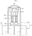
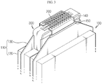
- FIGS. 2 and 3 are diagrams showing a state before a connector breaking device operates in the battery module according to an embodiment of the present disclosure
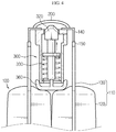
- FIG. 4 is a diagram showing that the connector breaking device is operated to move a breaking unit upwards, in the battery module according to an embodiment of the present disclosure
- FIG. 5 is a diagram showing a state where the connector breaking device is operated to move the breaking unit upwards so that an electric connection between a connector and an electrode lead is cut off, in the battery module according to an embodiment of the present disclosure.
- a battery module according to an embodiment of the present disclosure includes a pair of battery cells 100, a connector 200, and a connector breaking device 300.
- the pair of battery cells 100 may be, for example, pouch-type battery cells, and the pair of battery cells 100 may be stacked with their broad surfaces facing each other to form a battery cell stack.
- the battery cell 100 may include an electrode assembly (not shown), a pouch case 110, an electrode lead 140, and a sealant 150.
- the electrode assembly is configured so that a positive electrode plate, a separator, and a negative electrode plate are stacked in order at least once, and the separator is preferably disposed at an outermost side to ensure insulation.
- the electrode assembly may have various structures such as a winding type, a stacking type, or a stacking/folding type according to embodiments.
- the positive electrode plate is shaped so that a positive electrode active material is coated on at least one surface of a positive electrode current collector made of a conductive plate.
- the negative electrode plate is shaped so that a negative electrode active material is coated on at least one surface of a negative electrode current collector.
- the positive electrode plate and the negative electrode plate have uncoated regions that are not coated with the positive electrode active material and the negative electrode active material, and the uncoated regions function as electrode tabs that are coupled to the electrode lead 140.
- the separator is located between the positive electrode plate and the negative electrode plate, electrically insulates the positive electrode plate and the negative electrode plate from each other, and may have a porous membrane shape to allow lithium ions to move between the positive electrode plate and the negative electrode plate.
- the separator may be made of, for example, a porous film using polyethylene (PE) or polypropylene (PP), or a composite film thereof.
- the pouch case 110 may be a pouch case made of an exterior material having a multi-layered film shape having a metal layer and a resin layer surrounding the metal layer.
- the pouch case 110 may include an upper case and a lower case.
- the pouch case 110 includes the upper case and the lower case as above, the lower case has an accommodation portion 120 convexly protruding to accommodate the electrode assembly.
- the upper case may have a convexly protruding accommodation portion 120, and may also have a flat shape without the accommodation portion 120.
- the battery cell 100 may be a two-side protruding battery cell with both surfaces protruding or a one-side protruding battery cell with only one surface protruding.
- the figures of the present disclosure just depict a case where the battery cell 100 is a two-side protruding battery cell for convenience of illustration, but the present disclosure is not limited thereto.
- each of the upper case and the lower case may have a sealing portion 130 corresponding to an outer peripheral region of the accommodation portion 120.
- the lower case may have a sealing portion 130 corresponding to the outer peripheral region of the accommodation portion 120
- the upper case may have a sealing portion 130 formed in a region that is in contact with the sealing portion 130 of the lower case.
- the pouch case 110 accommodates the electrode assembly in the accommodation portion 120, and the sealing portions 130 of the upper case and the lower case are contacted and thermally bonded to each other for sealing.
- the sealing portions 130 of the upper case and the lower case may be made of a resin material with a thermally-bonding property so as to be adhered by thermal bonding in a mutually abutted state.
- the electrode lead 140 is a component connected to the electrode tab of the electrode assembly and drawn out of the pouch case 110 to serve as a medium for electrically connecting the electrode assembly to an external component, and includes a positive electrode lead connected to the positive electrode plate and a negative electrode lead connected to the negative electrode plate. More specifically, the positive electrode lead is connected to the positive electrode uncoated region provided at the positive electrode plate and the negative electrode lead is connected to the negative electrode uncoated region provided at the negative electrode plate.
- the positive electrode lead and the negative electrode lead provided at one battery cell 100 may be drawn in the same direction or in opposite directions.
- the figures of the present disclosure just depict a battery cell 100 in which the positive electrode lead and the negative electrode lead are drawn in opposite directions.
- the sealing portion 130 positioned in a direction in which the electrode lead 140 is drawn will be referred to as a terrace portion.
- the sealant 150 is interposed between an inner surface of the sealing portion 130 and the electrode lead 140 in order to prevent the sealing force from being lowered between the electrode lead 140 drawn out of the pouch case 110 and the inner surface of the sealing portion 130.
- the connector 200 is a component applied to electrically connect neighboring battery cells 100 to each other, and the connector 200 may be implemented to have, for example, a plurality of metal wires in order to minimize the electrical resistance and to be broken quickly and reliably when the connector breaking device 300 is operated.
- the respective metal wires may be connected to the electrode lead 140 of each of the pair of neighboring battery cells by welding or the like. If the connector breaking device 300 as described below is operated, the welding portion between the metal wire and the electrode lead 140 is broken to cut off the electric connection between the neighboring battery cells 100.
- the connector breaking device 300 is disposed in a space formed between the terrace portions of a pair of battery cells 100 facing each other. If swelling occurs at the battery cells 100, the connector breaking device 300 is operated with the pressure applied due to the swelling to cut off the electric connection between the connector 200 and the electrode lead 140.
- an end of the electrode lead 140 is bent in the horizontal direction and fixed to a top end of the connector breaking device 300, so that the pressure due to the operation of the connector breaking device 300 may be easily transmitted to the connector 200.
- a pushing bar 360 is pushed upwards by the accommodation portion 120 and/or the sealing portion 130 expanded due to the swelling of the battery cell 100, and accordingly, the breaking unit 320 moves upward to apply a pressure to the connector 200 and thus break the coupling portion between the connector 200 and the electrode lead 140, thereby cutting off the electric connection between the neighboring battery cells 100.
- breaking device 300 The detailed structure and operating principle of the breaking device 300 will be described later in detail with reference to FIGS. 9 to 12 .
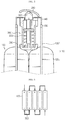
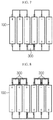
- FIGS. 6 to 8 are diagrams showing various positions at which the connector breaking device may be installed, in the battery module including a plurality of battery cells.
- the battery module according to the present disclosure may further include battery cells in addition to the pair of battery cells 100, and the electric connection relation among the plurality of battery cells 100 may be set in various ways.
- the plurality of battery cells 100 may be entirely connected in series. In this case, if any one of the plurality of connectors connecting the pairs of neighboring battery cells 100 is cut off, the electric connections are completely cut off.
- the connector breaking device 300 may be installed at only one place among the spaces formed between the terrace portions of the pair of neighboring battery cells 100. In order to more securely ensure the safety, it is also possible to install the connector breaking device 300 at several places in the spaces formed between the terrace portions of the pairs of neighboring battery cells 100.
- the plurality of battery cells 100 are divided into a plurality of cell groups, so that the battery cells 100 in the same cell group are connected in parallel and the cell groups are connected in series.
- FIG. 9 is a diagram showing an inner configuration of the connector breaking device applied to the battery module according to an embodiment of the present disclosure, in a state before the connector breaking device is operated
- FIG. 10 is a state where the movement of the breaking unit is limited due to a stopper, in the connector breaking device depicted in FIG. 9
- FIG. 11 is a diagram showing an inner configuration of the connector breaking device applied to the battery module according to an embodiment of the present disclosure, in a state after the connector breaking device is operated due to swelling of the battery cell
- FIG. 12 is a diagram showing a state where the fixed state of the breaking unit due to the stopper is released so that the breaking unit moves upwards, in the connector breaking device depicted in FIG. 11 .
- the connector breaking device 300 may include a cartridge 310, a breaking unit 320, a first elastic member 330, a stopper 340, a second elastic member 350, and a push bar 360.
- the cartridge 310 accommodates the breaking unit 320, the first elastic member 330, the stopper 340, the second elastic member 350 and the push bar 360 in an inner space thereof.
- the cartridge 310 includes a first placing portion 311 and a second placing portion 312 protruding from an inner surface thereof, a guide rib 313, and a support rib 314.
- the first placing portion 311 is formed below a first extension 321 of the breaking unit 320 and the first elastic member 330 to support the first elastic member 330, so that an end of the first extension 321 is placed thereon when the breaking unit 320 reaches a bottom dead point.
- the second placing portion 312 is formed below a second extension 322 of the breaking unit 320 to support an end of the second extension 322 to be placed thereon.
- the first extension 321 may be provided in a pair.
- the first placing portion 311 is also provided in a pair, and the second placing portion 312 may be provided between the pair of first placing portions 311.
- the guide rib 313 is located between one of the pair of first extensions 321 located at one side and the second extension 322 and is inclined at a predetermined angle with respect to a horizontal line.
- the guide rib 313 guides the movement of a push rib 361, explained later, so that the push rib 361 moves in the horizontal direction.
- the push rib 361 moves upwards identically when the push bar 360 moves upwards.
- the guide rib 313 functions to change the moving direction of the push bar 360 so that the push bar 360 moving only in the vertical direction may be moved in the horizontal direction.
- the support rib 314 is positioned between one of the first extensions 321 located at the other side and the second extension 322 and extends in the vertical direction.
- the support rib 314 functions to support one side of the second elastic member 350.
- the breaking unit 320 is a component that moves upwards through an opening formed at a top end of the cartridge due to the restoring force of the first elastic member 330, which is compressed to store the elastic energy, to break the coupling portion between the connector 200 and the electrode lead 140, thereby cutting off the electric connection between the connector 200 and the electrode lead 140.
- the breaking unit 320 includes the first extension 321 and the second extension 322 extending downwards, and the first extension 321 may be provided in a pair for stable movement of the breaking unit 320.
- the pair of first extensions 321 may be respectively provided at both ends of the breaking unit 320. If the first extension 321 is provided in a pair, the second extension 322 is located between the pair of first extensions 321.
- the first extension 321 may have a substantially elongated cylindrical shape extending in the vertical direction and is formed to have a thickness that may be inserted into the first elastic member 330.
- the figures of the present disclosure depict just a case where the first extension 321 has a cylindrical shape, but the present disclosure is not limited thereto, and the section of the first extension 321 may have a polygonal shape instead of the circular shape.
- the first extension 321 has an elastic member support portion 321a that is formed to have a thickness greater than that of the first elastic member 330, in order to support one side of the first elastic member 330.
- both ends of the first elastic member 330 are respectively supported by the elastic member support portion 321a and the first placing portion 311, and the first elastic member 330 behaves to be compressed when the breaking unit 320 moves downwards and to be elongated when the breaking unit 320 moves upwards.
- the second extension 322 may have a substantially elongated cylindrical shape extending in the vertical direction and is formed to have a thickness that may be inserted into a perforation hole 340a of the stopper 340.
- the figures of the present disclosure depict only a case where the second extension 322 has a cylindrical shape, but the present disclosure is not limited thereto, and the section of the second extension 322 may have a polygonal shape instead of the circular shape.
- the second extension 322 includes a first portion 322a having a first thickness and a second portion 322b having a second thickness that is thinner than the first portion 322a, and the second portion 322b may be located between the pair of first portions 322a.
- a step is formed due to a thickness difference.
- the stopper 340 may use the step to fix the breaking unit 320 not to be moved.
- the first elastic member 330 maintains a compressed state in a normal state where swelling over a predetermined level does not occur at the battery cell 100. However, if the pressure is applied to the push bar 360 due to the swelling, the first elastic member 330 is elongated to move the breaking unit 320 upwards by using the elastic energy.
- the first elastic member 330 may be, for example, a spring.
- Both sides of the first elastic member 330 are respectively supported by the elastic member support portion 321a and the first placing portion 311, and the first elastic member 330 behaves to be compressed when the breaking unit 320 moves downwards and to be when the breaking unit 320 moves upwards.
- the stopper 340 has a horizontally elongated shape and allows the first elastic member 330 to maintain an elastically compressed state. That is, the stopper 340 fixes the breaking unit 320 so that the breaking unit 320 maintains a state of being moved to the bottom dead point. In addition, if the push bar 360 is compressed due to the pressure applied by the swelling of the battery cell 100, the stopper 340 allows the fixed state of the breaking unit 320 to be released, so that the breaking unit 320 may move upwards toward the connector 200 by the elastic force of the first elastic member 330.
- the stopper 340 has a perforation hole 340a formed therethrough in the vertical direction, and the second extension 321 of the breaking unit 320 is inserted into the perforation hole 340a.
- the stopper 340 is disposed between the second elastic member 350 and the push rib 361, explained later, and receives a force in a direction toward the push rib 361 by the restoring force of the second elastic member 350. Accordingly, the inner wall of the perforation hole 340a of the stopper 340 is brought into contact with the second portion 322b of the second extension 322, and thus, the stopper 340 is caught to the step formed at the boundary region between the first portion 322a and the second portion 322b of the second extension 322 so that the breaking unit 320 maintains a fixed state not to move vertically.
- the first elastic member 330 is in the compressed state and the second elastic member 350 is in the elongated state.
- the second elastic member 350 maintains an elongated state when the breaking unit 320 is fixed by the stopper 340, and behaviors to be compressed when the pressure due to the swelling is applied to the push bar 360.
- the second elastic member 330 may be, for example, a spring.
- Both sides of the second elastic member 350 are respectively supported by the stopper 340 and the support rib 314.
- the second elastic member 350 is compressed if the push bar 360 is pressed to move upwards, and the second elastic member 350 is elongated to move the stopper 340 toward the push rib 361 when the push bar 360 is not pressed.
- the push bar 360 is installed at a lower portion inside the cartridge 310 and is exposed out of the cartridge 310 through an opening formed at a bottom end of the cartridge 310.
- the push bar 360 receives the pressure due to the swelling of the battery cell 100 to moves upwards inside the cartridge 310 so that the fixed state of the breaking unit 320 is released.
- the push bar 360 includes the push rib 361 that extends upwards toward the guide rib 313, and one end of the push rib 361 is located between the guide rib 313 and the stopper 340. If the push bar 360 moves upwards due to the pressure applied by the swelling, the push rib 361 changes the moving direction by the guide rib 313 to press the stopper 340, and thus the stopper 340 moves in a direction compressing the second elastic member 350.
- the fixed state of the breaking unit 320 is released due to the movement of the stopper 340, and thus the breaking unit 320 moves upwards due to the restoring force of the first elastic member 330 to hit the connector 200, so that the coupling portion between the connector 200 and the electrode lead 140 is broken.
- the battery module according to the present disclosure breaks the coupling portion between connector 200 and the electrode lead 140 by using the connector breaking device 300 disposed between neighboring battery cells 100, and thus it is possible to forcibly cut off the flow of current, thereby ensuring safety in use of a secondary battery.
Landscapes
- Chemical & Material Sciences (AREA)
- Chemical Kinetics & Catalysis (AREA)
- Electrochemistry (AREA)
- General Chemical & Material Sciences (AREA)
- Inorganic Chemistry (AREA)
- Connection Of Batteries Or Terminals (AREA)
- Battery Mounting, Suspending (AREA)
Abstract
Description
- The present disclosure relates to a battery module including a connector breaking device, and more particularly, to a battery module including a connector breaking device, which is operated due to swelling occurring at a battery cell to cut off an electric connection between neighboring battery cells.
- The present application claims priority to Korean Patent Application No.
10-2017-0111346 filed on August 31, 2017 - As portable electric products such as video cameras, cellular phones and portable PCs are used more broadly, the importance of secondary batteries mainly used as a driving power source therefor is increasing.
- A secondary battery capable of charging and discharging, different from a primary battery cannot be recharged is being actively studied in high-tech fields such as digital cameras, cellular phones, laptop computers, power tools, electric bicycles, electric vehicles, hybrid electric vehicles and mass-capacity power storage devices.
- In particular, a lithium secondary battery has a high energy density per unit weight and allows rapid charging, compared to other secondary batteries such as lead storage batteries, nickel-cadmium batteries, nickel-hydrogen batteries and nickel-zinc batteries, and thus it is used more and more.
- The lithium secondary battery has an operating voltage of 3.6V or above. The lithium secondary battery is used as a power source for a portable electronic device, or a plurality of lithium secondary batteries are connected in series or in parallel and used for a high output electric vehicle, a hybrid electric vehicle, a power tool, an electric bicycle, a power storage device or a UPS.
- The lithium secondary battery has an operating voltage three times higher than that of a nickel-cadmium battery or a nickel-metal hydride battery and has a high energy density per unit weight. For this reason, the lithium secondary battery tends to be used more and more.
- The lithium secondary battery may be classified into a lithium ion battery using a liquid electrolyte and a lithium ion polymer battery using a polymer solid electrolyte depending on an electrolyte type. In addition, the lithium ion polymer battery may be classified into a pure solid lithium ion polymer battery without containing any electrolyte and a lithium ion polymer battery using a gel polymer electrolyte containing an electrolytic solution, depending on a polymer solid electrolyte type.
- In the lithium ion battery using a liquid electrolyte, a cylindrical or rectangular metal can is generally used as a container in a welded and sealed form. Since the can-type secondary battery using the metal can as a container has a fixed shape, there is a disadvantage that it restricts the design of an electric product using the can-type secondary battery as a power source, and it is difficult to reduce the volume. Thus, a pouch-type secondary battery prepared by putting an electrode assembly and an electrolyte in a pouch packaging material made of a film and sealing the pouch packaging material has been developed and used.
- However, the lithium secondary battery has a risk of explosion when being overheated and thus it is important to secure safety. The lithium secondary battery is overheated due to various factors, one of which is an overcurrent flow above a limit through the lithium secondary battery. If the overcurrent flows, the lithium secondary battery is heated by the Joule heat, so the internal temperature of the battery rises rapidly. In addition, the rapid rise in temperature causes a decomposition reaction of the electrolyte, causing a thermal runaway, which eventually leads to the explosion of the battery. Overcurrent occurs in the case where a sharp metal object penetrates the lithium secondary battery, where the insulation between positive and negative electrodes is destroyed due to the shrinkage of a separator interposed between the positive and negative electrodes, where a rush current is applied to the battery due to abnormality of a charging circuit or a load connected to the outside, or the like.
- Thus, the lithium secondary battery is used in combination with a protecting circuit in order to protect the battery against an abnormal situation such as overcurrent, and the protecting circuit generally includes a fuse element for irreversibly disconnecting a line through which a charging or discharging current flows when overcurrent occurs.
-
FIG. 1 is a circuit diagram for illustrating an arrangement and an operating mechanism of a fuse element provided in a protecting circuit coupled to a battery pack including a lithium secondary battery. - As shown in
FIG. 1 , in order to protect the battery pack when overcurrent occurs, the protecting circuit includes a fuse element 1, asensing resistor 2 for sensing overcurrent, amicrocontroller 3 for monitoring the occurrence of overcurrent and operating the fuse element 1 when overcurrent occurs, and aswitch 4 for switching the inflow of an operating current to the fuse element 1. - The fuse element 1 is installed on a main line connected to an outermost terminal of the battery pack. The main line refers to a wiring through which a charging current or a discharging current flows. In
FIG. 1 , it is depicted that the fuse element 1 is installed at a high-potential line (Pack+). - The fuse element 1 is a three-terminal element, where two terminals are connected to the main line through which a charging or discharging current flows and one terminal is connected to the
switch 4. In addition, the fuse element 1 includes afuse 1a connected to the main line in series and melted and cut at a certain temperature and aresistor 1b for applying heat to thefuse 1a. - The
microcontroller 3 periodically detects the voltage at both ends of thesensing resistor 2 and monitors whether overcurrent occurs. If it is determined that overcurrent occurs, themicrocontroller 3 turns on theswitch 4. If so, the current flowing on the main line is bypassed to the fuse element 1 and applied to theresistor 1b. Accordingly, the Joule heat generated at theresistor 1b is conducted to thefuse 1a to raise the temperature of thefuse 1a. If the temperature of thefuse 1a rises to the melting temperature, thefuse 1a is melted and broken so that the main line is irreversibly disconnected. If the main line is disconnected, the overcurrent does not flow any more, thereby overcoming the problem caused by the overcurrent. - However, the above conventional technique has several problems. In other words, if the
microcontroller 3 is broken, theswitch 4 does not turn on even though overcurrent occurs. In this case, a current does not flow into theresistor 1b of the fuse element 1, and thus the fuse element 1 does not operate. Also, a space for disposing the fuse element 1 is separately required inside the protecting circuit, and a program algorithm for controlling the operation of the fuse element 1 must be loaded in themicrocontroller 3. Thus, it is disadvantageous that the space efficiency of the protecting circuit is deteriorated and the load of themicrocontroller 3 is increased. - The present disclosure is designed to solve the problems of the related art, and therefore the present disclosure is directed to ensuring safety in use of a secondary battery by rapidly cutting off the flow of current when swelling occurs at a battery cell over a certain level due to the occurrence of abnormal situation such as overcharge or short circuit.
- However, the technical problem to be solved by the present disclosure is not limited to the above, and other objects not mentioned herein will be understood from the following description by those skilled in the art.
- In one aspect of the present disclosure, there is provided a battery module, comprising: a pair of battery cells respectively having electrode leads and stacked to face each other; a connector configured to connect the electrode leads of the pair of battery cells; and a connector breaking device disposed in a space formed between terrace portions of the pair of battery cells and operated with a pressure applied due to swelling of the battery cells to cut off an electric connection between the connector and the electrode leads.
- The electrode leads respectively provided at the pair of battery cells may be fixed to the connector breaking device.
- The connector breaking device may include a push bar configured to move upwards inside a cartridge with a pressure applied due to swelling of the battery cell; a first elastic member configured to maintain an elastically compressed state in a direction opposite to the electrode lead and be restored when the push bar moves upwards; a breaking unit configured to move toward the connector through an opening formed at a top end of the cartridge due to a restoring force of the first elastic member to cut off an electric connection between the connector and the electrode lead; and a cartridge configured to accommodate the push bar, the first elastic member and the breaking unit.
- The connector breaking device may further include a stopper configured to fix the breaking unit so that the first elastic member maintains a compressed state, the stopper releasing a fixed state of the breaking unit when the push bar is compressed due to swelling so that the breaking unit moves toward the connector due to the restoring force of the first elastic member.
- The cartridge may include a guide rib formed to protrude from an inner surface thereof and inclined at a predetermined angle with respect to a horizontal line.
- The push bar may include a push rib extending upwards toward the guide rib and having one end located between the guide rib and the stopper.
- When the push bar is compressed due to the swelling, the push rib may change a moving direction by the guide rib so that one end of the push rib applies a pressure to one end of the stopper.
- The stopper may move with a pressure applied by the push rib to release the fixed state of the breaking unit.
- The cartridge may include a support rib formed to protrude from the inner surface thereof, and the connector breaking device may include a second elastic member disposed between the stopper and the support rib to be elastically compressed when the push bar is pressed.
- According to an embodiment of the present disclosure, it is possible to prevent fire or explosion from being generated at a secondary battery by rapidly cutting off the flow of current when swelling occurs at a battery cell over a certain level due to the occurrence of abnormal situation such as overcharge or short circuit.
- The accompanying drawings illustrate a preferred embodiment of the present disclosure and together with the foregoing disclosure, serve to provide further understanding of the technical features of the present disclosure, and thus, the present disclosure is not construed as being limited to the drawing.
-
FIG. 1 is a circuit diagram for illustrating an arrangement and an operating mechanism of a fuse element provided in a protecting circuit coupled to a battery module. -
FIGS. 2 and3 are diagrams showing a state before a connector breaking device operates in the battery module according to an embodiment of the present disclosure. -
FIG. 4 is a diagram showing that the connector breaking device is operated to move a breaking unit upwards, in the battery module according to an embodiment of the present disclosure. -
FIG. 5 is a diagram showing a state where the connector breaking device is operated to move the breaking unit upwards so that an electric connection between a connector and an electrode lead is cut off, in the battery module according to an embodiment of the present disclosure. -
FIGS. 6 to 8 are diagrams showing various positions at which the connector breaking device may be installed, in the battery module including a plurality of battery cells. -
FIG. 9 is a diagram showing an inner configuration of the connector breaking device applied to the battery module according to an embodiment of the present disclosure, in a state before the connector breaking device is operated. -
FIG. 10 is a state where the movement of the breaking unit is limited due to a stopper, in the connector breaking device depicted inFIG. 9 . -
FIG. 11 is a diagram showing an inner configuration of the connector breaking device applied to the battery module according to an embodiment of the present disclosure, in a state after the connector breaking device is operated due to swelling of the battery cell. -
FIG. 12 is a diagram showing a state where the fixed state of the breaking unit due to the stopper is released so that the breaking unit moves upwards, in the connector breaking device depicted inFIG. 11 . - Hereinafter, preferred embodiments of the present disclosure will be described in detail with reference to the accompanying drawings. Prior to the description, it should be understood that the terms used in the specification and the appended claims should not be construed as limited to general and dictionary meanings, but interpreted based on the meanings and concepts corresponding to technical aspects of the present disclosure on the basis of the principle that the inventor is allowed to define terms appropriately for the best explanation. Therefore, the description proposed herein is just a preferable example for the purpose of illustrations only, not intended to limit the scope of the disclosure, so it should be understood that other equivalents and modifications could be made thereto without departing from the scope of the disclosure.
- First, the overall configuration of a battery module according to an embodiment of the present disclosure will be described with reference to
FIGS. 2 to 5 . -
FIGS. 2 and3 are diagrams showing a state before a connector breaking device operates in the battery module according to an embodiment of the present disclosure, andFIG. 4 is a diagram showing that the connector breaking device is operated to move a breaking unit upwards, in the battery module according to an embodiment of the present disclosure. In addition,FIG. 5 is a diagram showing a state where the connector breaking device is operated to move the breaking unit upwards so that an electric connection between a connector and an electrode lead is cut off, in the battery module according to an embodiment of the present disclosure. - Referring to
FIGS. 2 to 5 , a battery module according to an embodiment of the present disclosure includes a pair ofbattery cells 100, aconnector 200, and aconnector breaking device 300. - The pair of
battery cells 100 may be, for example, pouch-type battery cells, and the pair ofbattery cells 100 may be stacked with their broad surfaces facing each other to form a battery cell stack. Thebattery cell 100 may include an electrode assembly (not shown), apouch case 110, anelectrode lead 140, and asealant 150. - The electrode assembly is configured so that a positive electrode plate, a separator, and a negative electrode plate are stacked in order at least once, and the separator is preferably disposed at an outermost side to ensure insulation. The electrode assembly may have various structures such as a winding type, a stacking type, or a stacking/folding type according to embodiments.
- The positive electrode plate is shaped so that a positive electrode active material is coated on at least one surface of a positive electrode current collector made of a conductive plate. Likewise, the negative electrode plate is shaped so that a negative electrode active material is coated on at least one surface of a negative electrode current collector.
- The positive electrode plate and the negative electrode plate have uncoated regions that are not coated with the positive electrode active material and the negative electrode active material, and the uncoated regions function as electrode tabs that are coupled to the
electrode lead 140. - The separator is located between the positive electrode plate and the negative electrode plate, electrically insulates the positive electrode plate and the negative electrode plate from each other, and may have a porous membrane shape to allow lithium ions to move between the positive electrode plate and the negative electrode plate. The separator may be made of, for example, a porous film using polyethylene (PE) or polypropylene (PP), or a composite film thereof.
- The
pouch case 110 may be a pouch case made of an exterior material having a multi-layered film shape having a metal layer and a resin layer surrounding the metal layer. Thepouch case 110 may include an upper case and a lower case. - Thus, if the
pouch case 110 includes the upper case and the lower case as above, the lower case has anaccommodation portion 120 convexly protruding to accommodate the electrode assembly. Also, the upper case may have a convexly protrudingaccommodation portion 120, and may also have a flat shape without theaccommodation portion 120. - That is, the
battery cell 100 may be a two-side protruding battery cell with both surfaces protruding or a one-side protruding battery cell with only one surface protruding. The figures of the present disclosure just depict a case where thebattery cell 100 is a two-side protruding battery cell for convenience of illustration, but the present disclosure is not limited thereto. - Meanwhile, if the battery cell is a two-side protruding battery cell, each of the upper case and the lower case may have a sealing
portion 130 corresponding to an outer peripheral region of theaccommodation portion 120. In addition, if thebattery cell 100 is a one-side protruding battery cell, the lower case may have a sealingportion 130 corresponding to the outer peripheral region of theaccommodation portion 120, and the upper case may have a sealingportion 130 formed in a region that is in contact with the sealingportion 130 of the lower case. - The
pouch case 110 accommodates the electrode assembly in theaccommodation portion 120, and the sealingportions 130 of the upper case and the lower case are contacted and thermally bonded to each other for sealing. As described above, the sealingportions 130 of the upper case and the lower case may be made of a resin material with a thermally-bonding property so as to be adhered by thermal bonding in a mutually abutted state. - The
electrode lead 140 is a component connected to the electrode tab of the electrode assembly and drawn out of thepouch case 110 to serve as a medium for electrically connecting the electrode assembly to an external component, and includes a positive electrode lead connected to the positive electrode plate and a negative electrode lead connected to the negative electrode plate. More specifically, the positive electrode lead is connected to the positive electrode uncoated region provided at the positive electrode plate and the negative electrode lead is connected to the negative electrode uncoated region provided at the negative electrode plate. - The positive electrode lead and the negative electrode lead provided at one
battery cell 100 may be drawn in the same direction or in opposite directions. The figures of the present disclosure just depict abattery cell 100 in which the positive electrode lead and the negative electrode lead are drawn in opposite directions. - Meanwhile, in describing the present disclosure, among the sealing
portions 130, the sealingportion 130 positioned in a direction in which theelectrode lead 140 is drawn will be referred to as a terrace portion. - The
sealant 150 is interposed between an inner surface of the sealingportion 130 and theelectrode lead 140 in order to prevent the sealing force from being lowered between theelectrode lead 140 drawn out of thepouch case 110 and the inner surface of the sealingportion 130. - The
connector 200 is a component applied to electrically connect neighboringbattery cells 100 to each other, and theconnector 200 may be implemented to have, for example, a plurality of metal wires in order to minimize the electrical resistance and to be broken quickly and reliably when theconnector breaking device 300 is operated. - In this case, the respective metal wires may be connected to the
electrode lead 140 of each of the pair of neighboring battery cells by welding or the like. If theconnector breaking device 300 as described below is operated, the welding portion between the metal wire and theelectrode lead 140 is broken to cut off the electric connection between the neighboringbattery cells 100. - The
connector breaking device 300 is disposed in a space formed between the terrace portions of a pair ofbattery cells 100 facing each other. If swelling occurs at thebattery cells 100, theconnector breaking device 300 is operated with the pressure applied due to the swelling to cut off the electric connection between theconnector 200 and theelectrode lead 140. - At this time, an end of the
electrode lead 140 is bent in the horizontal direction and fixed to a top end of theconnector breaking device 300, so that the pressure due to the operation of theconnector breaking device 300 may be easily transmitted to theconnector 200. - A pushing
bar 360 is pushed upwards by theaccommodation portion 120 and/or the sealingportion 130 expanded due to the swelling of thebattery cell 100, and accordingly, thebreaking unit 320 moves upward to apply a pressure to theconnector 200 and thus break the coupling portion between theconnector 200 and theelectrode lead 140, thereby cutting off the electric connection between the neighboringbattery cells 100. - The detailed structure and operating principle of the
breaking device 300 will be described later in detail with reference toFIGS. 9 to 12 . - Next, the location where the
connector breaking device 300 is installed in the battery module according to the present disclosure will be described with reference toFIGS. 6 to 8 . -
FIGS. 6 to 8 are diagrams showing various positions at which the connector breaking device may be installed, in the battery module including a plurality of battery cells. - Referring to
FIGS. 6 to 8 , the battery module according to the present disclosure may further include battery cells in addition to the pair ofbattery cells 100, and the electric connection relation among the plurality ofbattery cells 100 may be set in various ways. - In the battery module according to the present disclosure, as shown in
FIG. 6 , the plurality ofbattery cells 100 may be entirely connected in series. In this case, if any one of the plurality of connectors connecting the pairs of neighboringbattery cells 100 is cut off, the electric connections are completely cut off. Thus, theconnector breaking device 300 may be installed at only one place among the spaces formed between the terrace portions of the pair of neighboringbattery cells 100. In order to more securely ensure the safety, it is also possible to install theconnector breaking device 300 at several places in the spaces formed between the terrace portions of the pairs of neighboringbattery cells 100. - Also, in the battery module according to the present disclosure, as shown in
FIGS. 7 and 8 , the plurality ofbattery cells 100 are divided into a plurality of cell groups, so that thebattery cells 100 in the same cell group are connected in parallel and the cell groups are connected in series. - In this case, as shown in
FIG. 7 , by installing theconnector breaking devices 300 in spaces formed between the terrace portions of the pairs of neighboringbattery cells 100 belonging to different cell groups, it is possible to cut off the serial connection between the cell groups when cell swelling over a certain level occurs. - Meanwhile, in this case, as shown in
FIG. 8 , by installing theconnector breaking device 300 in every space formed between the terrace portions of the pair of neighboringbattery cells 100 belonging to the same cell group, it is possible to cut off the parallel connection in the same cell group when cell swelling over a certain level occurs. - Next, the detailed structure and operation principle of the
connector breaking device 300 applied to the battery module according to an embodiment of the present disclosure will be described with reference toFIGS. 9 to 12 . -
FIG. 9 is a diagram showing an inner configuration of the connector breaking device applied to the battery module according to an embodiment of the present disclosure, in a state before the connector breaking device is operated, andFIG. 10 is a state where the movement of the breaking unit is limited due to a stopper, in the connector breaking device depicted inFIG. 9 . In addition,FIG. 11 is a diagram showing an inner configuration of the connector breaking device applied to the battery module according to an embodiment of the present disclosure, in a state after the connector breaking device is operated due to swelling of the battery cell, andFIG. 12 is a diagram showing a state where the fixed state of the breaking unit due to the stopper is released so that the breaking unit moves upwards, in the connector breaking device depicted inFIG. 11 . - First, referring to
FIGS. 9 to 12 , theconnector breaking device 300 may include acartridge 310, abreaking unit 320, a firstelastic member 330, astopper 340, a secondelastic member 350, and apush bar 360. - The
cartridge 310 accommodates thebreaking unit 320, the firstelastic member 330, thestopper 340, the secondelastic member 350 and thepush bar 360 in an inner space thereof. Thecartridge 310 includes afirst placing portion 311 and asecond placing portion 312 protruding from an inner surface thereof, aguide rib 313, and asupport rib 314. - The
first placing portion 311 is formed below afirst extension 321 of thebreaking unit 320 and the firstelastic member 330 to support the firstelastic member 330, so that an end of thefirst extension 321 is placed thereon when thebreaking unit 320 reaches a bottom dead point. Similarly, thesecond placing portion 312 is formed below asecond extension 322 of thebreaking unit 320 to support an end of thesecond extension 322 to be placed thereon. - As described later, the
first extension 321 may be provided in a pair. In this case, thefirst placing portion 311 is also provided in a pair, and thesecond placing portion 312 may be provided between the pair offirst placing portions 311. - The
guide rib 313 is located between one of the pair offirst extensions 321 located at one side and thesecond extension 322 and is inclined at a predetermined angle with respect to a horizontal line. Theguide rib 313 guides the movement of apush rib 361, explained later, so that thepush rib 361 moves in the horizontal direction. In other words, thepush rib 361 moves upwards identically when thepush bar 360 moves upwards. Here, theguide rib 313 functions to change the moving direction of thepush bar 360 so that thepush bar 360 moving only in the vertical direction may be moved in the horizontal direction. - The
support rib 314 is positioned between one of thefirst extensions 321 located at the other side and thesecond extension 322 and extends in the vertical direction. Thesupport rib 314 functions to support one side of the secondelastic member 350. - The
breaking unit 320 is a component that moves upwards through an opening formed at a top end of the cartridge due to the restoring force of the firstelastic member 330, which is compressed to store the elastic energy, to break the coupling portion between theconnector 200 and theelectrode lead 140, thereby cutting off the electric connection between theconnector 200 and theelectrode lead 140. - The
breaking unit 320 includes thefirst extension 321 and thesecond extension 322 extending downwards, and thefirst extension 321 may be provided in a pair for stable movement of thebreaking unit 320. In this case, the pair offirst extensions 321 may be respectively provided at both ends of thebreaking unit 320. If thefirst extension 321 is provided in a pair, thesecond extension 322 is located between the pair offirst extensions 321. - The
first extension 321 may have a substantially elongated cylindrical shape extending in the vertical direction and is formed to have a thickness that may be inserted into the firstelastic member 330. The figures of the present disclosure depict just a case where thefirst extension 321 has a cylindrical shape, but the present disclosure is not limited thereto, and the section of thefirst extension 321 may have a polygonal shape instead of the circular shape. - The
first extension 321 has an elasticmember support portion 321a that is formed to have a thickness greater than that of the firstelastic member 330, in order to support one side of the firstelastic member 330. As a result, both ends of the firstelastic member 330 are respectively supported by the elasticmember support portion 321a and thefirst placing portion 311, and the firstelastic member 330 behaves to be compressed when thebreaking unit 320 moves downwards and to be elongated when thebreaking unit 320 moves upwards. - The
second extension 322 may have a substantially elongated cylindrical shape extending in the vertical direction and is formed to have a thickness that may be inserted into aperforation hole 340a of thestopper 340. The figures of the present disclosure depict only a case where thesecond extension 322 has a cylindrical shape, but the present disclosure is not limited thereto, and the section of thesecond extension 322 may have a polygonal shape instead of the circular shape. - The
second extension 322 includes afirst portion 322a having a first thickness and asecond portion 322b having a second thickness that is thinner than thefirst portion 322a, and thesecond portion 322b may be located between the pair offirst portions 322a. - In the boundary region between the
first portion 322a and thesecond portion 322b formed with different thicknesses, a step is formed due to a thickness difference. Thestopper 340 may use the step to fix thebreaking unit 320 not to be moved. - The first
elastic member 330 maintains a compressed state in a normal state where swelling over a predetermined level does not occur at thebattery cell 100. However, if the pressure is applied to thepush bar 360 due to the swelling, the firstelastic member 330 is elongated to move thebreaking unit 320 upwards by using the elastic energy. The firstelastic member 330 may be, for example, a spring. - Both sides of the first
elastic member 330 are respectively supported by the elasticmember support portion 321a and thefirst placing portion 311, and the firstelastic member 330 behaves to be compressed when thebreaking unit 320 moves downwards and to be when thebreaking unit 320 moves upwards. - The
stopper 340 has a horizontally elongated shape and allows the firstelastic member 330 to maintain an elastically compressed state. That is, thestopper 340 fixes thebreaking unit 320 so that thebreaking unit 320 maintains a state of being moved to the bottom dead point. In addition, if thepush bar 360 is compressed due to the pressure applied by the swelling of thebattery cell 100, thestopper 340 allows the fixed state of thebreaking unit 320 to be released, so that thebreaking unit 320 may move upwards toward theconnector 200 by the elastic force of the firstelastic member 330. - The
stopper 340 has aperforation hole 340a formed therethrough in the vertical direction, and thesecond extension 321 of thebreaking unit 320 is inserted into theperforation hole 340a. - The
stopper 340 is disposed between the secondelastic member 350 and thepush rib 361, explained later, and receives a force in a direction toward thepush rib 361 by the restoring force of the secondelastic member 350. Accordingly, the inner wall of theperforation hole 340a of thestopper 340 is brought into contact with thesecond portion 322b of thesecond extension 322, and thus, thestopper 340 is caught to the step formed at the boundary region between thefirst portion 322a and thesecond portion 322b of thesecond extension 322 so that thebreaking unit 320 maintains a fixed state not to move vertically. - Meanwhile, in a state where the
stopper 340 is caught to the step, the firstelastic member 330 is in the compressed state and the secondelastic member 350 is in the elongated state. - The second
elastic member 350 maintains an elongated state when thebreaking unit 320 is fixed by thestopper 340, and behaviors to be compressed when the pressure due to the swelling is applied to thepush bar 360. The secondelastic member 330 may be, for example, a spring. - Both sides of the second
elastic member 350 are respectively supported by thestopper 340 and thesupport rib 314. The secondelastic member 350 is compressed if thepush bar 360 is pressed to move upwards, and the secondelastic member 350 is elongated to move thestopper 340 toward thepush rib 361 when thepush bar 360 is not pressed. - The
push bar 360 is installed at a lower portion inside thecartridge 310 and is exposed out of thecartridge 310 through an opening formed at a bottom end of thecartridge 310. Thepush bar 360 receives the pressure due to the swelling of thebattery cell 100 to moves upwards inside thecartridge 310 so that the fixed state of thebreaking unit 320 is released. - The
push bar 360 includes thepush rib 361 that extends upwards toward theguide rib 313, and one end of thepush rib 361 is located between theguide rib 313 and thestopper 340. If thepush bar 360 moves upwards due to the pressure applied by the swelling, thepush rib 361 changes the moving direction by theguide rib 313 to press thestopper 340, and thus thestopper 340 moves in a direction compressing the secondelastic member 350. - Referring to
FIGS. 10 and12 together, the fixed state of thebreaking unit 320 is released due to the movement of thestopper 340, and thus thebreaking unit 320 moves upwards due to the restoring force of the firstelastic member 330 to hit theconnector 200, so that the coupling portion between theconnector 200 and theelectrode lead 140 is broken. - As described above, when the swelling over a certain level occurs at the
battery cell 100, the battery module according to the present disclosure breaks the coupling portion betweenconnector 200 and theelectrode lead 140 by using theconnector breaking device 300 disposed between neighboringbattery cells 100, and thus it is possible to forcibly cut off the flow of current, thereby ensuring safety in use of a secondary battery. - The present disclosure has been described in detail. However, it should be understood that the detailed description and specific examples, while indicating preferred embodiments of the disclosure, are given by way of illustration only, since various changes and modifications within the scope of the disclosure will become apparent to those skilled in the art from this detailed description.
Claims (9)
- A battery module, comprising:a pair of battery cells respectively having electrode leads and stacked to face each other;a connector configured to connect the electrode leads of the pair of battery cells; anda connector breaking device disposed in a space formed between terrace portions of the pair of battery cells and operated with a pressure applied due to swelling of the battery cells so as to cut off an electric connection between the connector and the electrode leads.
- The battery module according to claim 1,
wherein the electrode leads respectively provided at the pair of battery cells are fixed to the connector breaking device. - The battery module according to claim 1, wherein the connector breaking device includes:a push bar configured to move upwards inside a cartridge with a pressure applied due to swelling of the battery cell;
a first elastic member configured to maintain an elastically compressed state in a direction opposite to the electrode lead and be restored when the push bar moves upwards; and
a breaking unit configured to move toward the connector through an opening formed at a top end of the cartridge due to a restoring force of the first elastic member so as to cut off an electric connection between the connector and the electrode lead,
a cartridge configured to accommodate the push bar, the first elastic member and the breaking unit. - The battery module according to claim 3,
wherein the connector breaking device further includes a stopper configured to fix the breaking unit so that the first elastic member maintains a compressed state, the stopper releasing a fixed state of the breaking unit when the push bar is compressed due to swelling so that the breaking unit moves toward the connector due to the restoring force of the first elastic member. - The battery module according to claim 4,
wherein the cartridge includes a guide rib formed to protrude from an inner surface thereof and inclined at a predetermined angle with respect to a horizontal line. - The battery module according to claim 5,
wherein the push bar includes a push rib extending upwards toward the guide rib and having one end located between the guide rib and the stopper. - The battery module according to claim 6,
wherein when the push bar is compressed due to the swelling, the push rib changes a moving direction by the guide rib so that one end of the push rib applies a pressure to one end of the stopper. - The battery module according to claim 7,
wherein the stopper moves with a pressure applied by the push rib to release the fixed state of the breaking unit. - The battery module according to claim 6,
wherein the cartridge includes a support rib formed to protrude from the inner surface thereof, and
wherein the connector breaking device includes a second elastic member disposed between the stopper and the support rib to be elastically compressed when the push bar is pressed.
Priority Applications (1)
| Application Number | Priority Date | Filing Date | Title |
|---|---|---|---|
| PL18851355T PL3598532T3 (en) | 2017-08-31 | 2018-06-18 | Battery module provided with connector breaking device |
Applications Claiming Priority (2)
| Application Number | Priority Date | Filing Date | Title |
|---|---|---|---|
| KR1020170111346A KR102259412B1 (en) | 2017-08-31 | 2017-08-31 | Battery bodule comprising a connector breaking device |
| PCT/KR2018/006859 WO2019045238A1 (en) | 2017-08-31 | 2018-06-18 | Battery module provided with connector breaking device |
Publications (3)
| Publication Number | Publication Date |
|---|---|
| EP3598532A1 true EP3598532A1 (en) | 2020-01-22 |
| EP3598532A4 EP3598532A4 (en) | 2020-07-01 |
| EP3598532B1 EP3598532B1 (en) | 2021-05-19 |
Family
ID=65527735
Family Applications (1)
| Application Number | Title | Priority Date | Filing Date |
|---|---|---|---|
| EP18851355.0A Active EP3598532B1 (en) | 2017-08-31 | 2018-06-18 | Battery module provided with connector breaking device |
Country Status (7)
| Country | Link |
|---|---|
| US (1) | US10998597B2 (en) |
| EP (1) | EP3598532B1 (en) |
| JP (1) | JP7037019B2 (en) |
| KR (1) | KR102259412B1 (en) |
| CN (1) | CN110114912B (en) |
| PL (1) | PL3598532T3 (en) |
| WO (1) | WO2019045238A1 (en) |
Cited By (3)
| Publication number | Priority date | Publication date | Assignee | Title |
|---|---|---|---|---|
| GB2589073A (en) * | 2019-11-05 | 2021-05-26 | Dyson Technology Ltd | Battery pack |
| EP4216364A1 (en) * | 2022-01-21 | 2023-07-26 | Dongguan Poweramp Technology Limited | Circuit connection apparatus, battery module, and electrical device |
| EP4318790A4 (en) * | 2021-03-30 | 2024-11-20 | Dongguan Poweramp Technology Limited | Battery module and power-consuming device |
Families Citing this family (9)
| Publication number | Priority date | Publication date | Assignee | Title |
|---|---|---|---|---|
| DE102018205629A1 (en) * | 2018-04-13 | 2019-10-17 | Ford Global Technologies, Llc | High-voltage battery for a motor vehicle |
| KR102541537B1 (en) * | 2019-06-25 | 2023-06-08 | 주식회사 엘지에너지솔루션 | Battery module and battery pack including the same |
| KR20210126979A (en) * | 2020-04-13 | 2021-10-21 | 삼성에스디아이 주식회사 | Battery Module |
| CN113540703B (en) * | 2021-07-15 | 2022-08-23 | 东莞新能安科技有限公司 | Battery pack and electrical connection device |
| CN113764795B (en) * | 2021-08-11 | 2025-04-04 | 湖北亿纬动力有限公司 | Battery Module |
| CN114343861B (en) * | 2022-01-21 | 2023-07-21 | 浙江帝诺医疗科技有限公司 | Trolley of safety protection radio diagnosis system |
| CN114374060B (en) * | 2022-03-22 | 2022-06-14 | 深圳市青之鸟科技有限公司 | Be applied to plant protection unmanned aerial vehicle's group battery |
| TWI850934B (en) * | 2022-12-29 | 2024-08-01 | 宏碁股份有限公司 | Chargeable battery system and chargeable battery module thereof |
| US20240421410A1 (en) * | 2023-06-16 | 2024-12-19 | Microsoft Technology Licensing, Llc | Modular attachment of tabbed battery cells |
Family Cites Families (20)
| Publication number | Priority date | Publication date | Assignee | Title |
|---|---|---|---|---|
| JP2007520180A (en) | 2003-10-14 | 2007-07-19 | ブラック アンド デッカー インク | Secondary battery, power tool, charger, and protection method, protection circuit, and protection device for battery pack adapted to provide protection from battery pack failure conditions |
| TW200840170A (en) | 2007-03-30 | 2008-10-01 | Amita Technologies Inc | Power disconnection safety structure for preventing soft-shell lithium-ion battery overcharging |
| KR101046192B1 (en) | 2007-10-30 | 2011-07-05 | 에스케이이노베이션 주식회사 | Overcharge safety device for secondary battery |
| US20090159354A1 (en) * | 2007-12-25 | 2009-06-25 | Wenfeng Jiang | Battery system having interconnected battery packs each having multiple electrochemical storage cells |
| KR101608694B1 (en) | 2009-07-20 | 2016-04-05 | 에스케이이노베이션 주식회사 | A Safeguard Apparatus Preventing Overcharge for A Secondary Battery |
| JP2011210390A (en) * | 2010-03-29 | 2011-10-20 | Honda Motor Co Ltd | Battery and battery module |
| KR101294168B1 (en) * | 2011-09-26 | 2013-08-08 | 기아자동차주식회사 | Apparatus for preventing overcharge battery |
| KR101383167B1 (en) * | 2011-10-20 | 2014-04-10 | 주식회사 엘지화학 | Battery Pack of Improved Safety |
| KR101404712B1 (en) * | 2012-01-26 | 2014-06-09 | 주식회사 엘지화학 | Battery Pack of Improved Safety |
| KR101524002B1 (en) | 2012-09-24 | 2015-05-29 | 주식회사 엘지화학 | Battery Pack employed Automatic Electrical Switch |
| KR101428331B1 (en) | 2012-12-27 | 2014-08-07 | 현대자동차주식회사 | Safety apparatus of battery module for vehicle |
| KR20140129401A (en) | 2013-04-18 | 2014-11-07 | 에스케이이노베이션 주식회사 | Battery Module |
| KR101449307B1 (en) * | 2013-06-28 | 2014-10-08 | 현대자동차주식회사 | Battery safety device |
| KR101500229B1 (en) | 2013-12-18 | 2015-03-06 | 현대자동차주식회사 | Apparatus for preventing over-charge for battery of vehicle |
| KR101558685B1 (en) | 2013-12-09 | 2015-10-07 | 현대자동차주식회사 | System And Method for providing a Communication Service, and Vehicle supporting the same |
| KR101500222B1 (en) * | 2013-12-18 | 2015-03-06 | 현대자동차주식회사 | Apparatus for preventing over charging of battery |
| KR20160026469A (en) * | 2014-09-01 | 2016-03-09 | 에스케이이노베이션 주식회사 | battery module having bus bar integrated with low-voltage sensing module |
| KR20170016065A (en) | 2015-08-03 | 2017-02-13 | 에스케이이노베이션 주식회사 | Secondary battery |
| KR102092852B1 (en) * | 2015-09-30 | 2020-03-24 | 주식회사 엘지화학 | Battery Pack |
| KR101970248B1 (en) | 2016-03-28 | 2019-04-18 | 엘지전자 주식회사 | Air Conditioner |
-
2017
- 2017-08-31 KR KR1020170111346A patent/KR102259412B1/en active Active
-
2018
- 2018-06-18 CN CN201880005383.8A patent/CN110114912B/en active Active
- 2018-06-18 JP JP2019547094A patent/JP7037019B2/en active Active
- 2018-06-18 US US16/469,411 patent/US10998597B2/en active Active
- 2018-06-18 PL PL18851355T patent/PL3598532T3/en unknown
- 2018-06-18 EP EP18851355.0A patent/EP3598532B1/en active Active
- 2018-06-18 WO PCT/KR2018/006859 patent/WO2019045238A1/en not_active Ceased
Cited By (3)
| Publication number | Priority date | Publication date | Assignee | Title |
|---|---|---|---|---|
| GB2589073A (en) * | 2019-11-05 | 2021-05-26 | Dyson Technology Ltd | Battery pack |
| EP4318790A4 (en) * | 2021-03-30 | 2024-11-20 | Dongguan Poweramp Technology Limited | Battery module and power-consuming device |
| EP4216364A1 (en) * | 2022-01-21 | 2023-07-26 | Dongguan Poweramp Technology Limited | Circuit connection apparatus, battery module, and electrical device |
Also Published As
| Publication number | Publication date |
|---|---|
| EP3598532A4 (en) | 2020-07-01 |
| JP7037019B2 (en) | 2022-03-16 |
| JP2020509547A (en) | 2020-03-26 |
| PL3598532T3 (en) | 2021-11-08 |
| WO2019045238A1 (en) | 2019-03-07 |
| CN110114912A (en) | 2019-08-09 |
| KR102259412B1 (en) | 2021-06-01 |
| US20200099024A1 (en) | 2020-03-26 |
| EP3598532B1 (en) | 2021-05-19 |
| KR20190024392A (en) | 2019-03-08 |
| CN110114912B (en) | 2022-03-04 |
| US10998597B2 (en) | 2021-05-04 |
Similar Documents
| Publication | Publication Date | Title |
|---|---|---|
| EP3598532B1 (en) | Battery module provided with connector breaking device | |
| EP3618148B1 (en) | Battery module having structure breaking connector by using venting gas | |
| EP3525256B1 (en) | Battery module and battery pack with improved safety | |
| CN109844996B (en) | Battery module, battery pack including the same, and vehicle | |
| KR101370265B1 (en) | Secondary battery, Element for secondary battery applied for it and Method of manufacturing the same | |
| CN106941148B (en) | Battery unit | |
| KR101753213B1 (en) | Battery cell and Secondary battery assembly comprising the same | |
| KR101734703B1 (en) | Battery Cell | |
| KR101766047B1 (en) | Battery Cell | |
| KR20150034498A (en) | Battery cell with venting cover and Secondary battery comprising the same | |
| EP3540816B1 (en) | Battery cell with improved safety | |
| CN115699428A (en) | Battery pack and vehicle including the same | |
| KR20140129600A (en) | Secondary battery and Component for secondary battery applied for it | |
| KR20150062688A (en) | Battery cell, Battery module and battery pack comprising the same | |
| KR20180090100A (en) | Short circuiting Structure for Lithium Secondary Battery Having Excellent Stability against Overcharge and Pouch Type Lithium Secondary Battery Comprising the Same | |
| KR20150045241A (en) | Battery cell equipped with disconnection device, and Battery module and Battery pack comprising the same | |
| KR102267056B1 (en) | Battery module, battery pack including the same, and vehicle including the same |
Legal Events
| Date | Code | Title | Description |
|---|---|---|---|
| STAA | Information on the status of an ep patent application or granted ep patent |
Free format text: STATUS: THE INTERNATIONAL PUBLICATION HAS BEEN MADE |
|
| PUAI | Public reference made under article 153(3) epc to a published international application that has entered the european phase |
Free format text: ORIGINAL CODE: 0009012 |
|
| STAA | Information on the status of an ep patent application or granted ep patent |
Free format text: STATUS: REQUEST FOR EXAMINATION WAS MADE |
|
| 17P | Request for examination filed |
Effective date: 20191014 |
|
| AK | Designated contracting states |
Kind code of ref document: A1 Designated state(s): AL AT BE BG CH CY CZ DE DK EE ES FI FR GB GR HR HU IE IS IT LI LT LU LV MC MK MT NL NO PL PT RO RS SE SI SK SM TR |
|
| AX | Request for extension of the european patent |
Extension state: BA ME |
|
| A4 | Supplementary search report drawn up and despatched |
Effective date: 20200529 |
|
| RIC1 | Information provided on ipc code assigned before grant |
Ipc: H01M 2/34 20060101AFI20200525BHEP Ipc: H01M 2/20 20060101ALI20200525BHEP Ipc: H01M 2/02 20060101ALI20200525BHEP Ipc: H01M 2/26 20060101ALI20200525BHEP |
|
| DAV | Request for validation of the european patent (deleted) | ||
| DAX | Request for extension of the european patent (deleted) | ||
| REG | Reference to a national code |
Ref country code: DE Ref legal event code: R079 Ref document number: 602018017470 Country of ref document: DE Free format text: PREVIOUS MAIN CLASS: H01M0002340000 Ipc: H01M0050578000 |
|
| GRAP | Despatch of communication of intention to grant a patent |
Free format text: ORIGINAL CODE: EPIDOSNIGR1 |
|
| STAA | Information on the status of an ep patent application or granted ep patent |
Free format text: STATUS: GRANT OF PATENT IS INTENDED |
|
| RIC1 | Information provided on ipc code assigned before grant |
Ipc: H01M 50/572 20210101ALI20210222BHEP Ipc: H01M 50/116 20210101ALI20210222BHEP Ipc: H01M 50/531 20210101ALI20210222BHEP Ipc: H01M 50/50 20210101ALI20210222BHEP Ipc: H01M 50/543 20210101ALI20210222BHEP Ipc: H01M 50/578 20210101AFI20210222BHEP |
|
| INTG | Intention to grant announced |
Effective date: 20210309 |
|
| GRAS | Grant fee paid |
Free format text: ORIGINAL CODE: EPIDOSNIGR3 |
|
| GRAA | (expected) grant |
Free format text: ORIGINAL CODE: 0009210 |
|
| STAA | Information on the status of an ep patent application or granted ep patent |
Free format text: STATUS: THE PATENT HAS BEEN GRANTED |
|
| AK | Designated contracting states |
Kind code of ref document: B1 Designated state(s): AL AT BE BG CH CY CZ DE DK EE ES FI FR GB GR HR HU IE IS IT LI LT LU LV MC MK MT NL NO PL PT RO RS SE SI SK SM TR |
|
| REG | Reference to a national code |
Ref country code: GB Ref legal event code: FG4D |
|
| REG | Reference to a national code |
Ref country code: CH Ref legal event code: EP |
|
| REG | Reference to a national code |
Ref country code: DE Ref legal event code: R096 Ref document number: 602018017470 Country of ref document: DE |
|
| REG | Reference to a national code |
Ref country code: AT Ref legal event code: REF Ref document number: 1394883 Country of ref document: AT Kind code of ref document: T Effective date: 20210615 |
|
| REG | Reference to a national code |
Ref country code: IE Ref legal event code: FG4D |
|
| REG | Reference to a national code |
Ref country code: SE Ref legal event code: TRGR |
|
| REG | Reference to a national code |
Ref country code: LT Ref legal event code: MG9D |
|
| REG | Reference to a national code |
Ref country code: AT Ref legal event code: MK05 Ref document number: 1394883 Country of ref document: AT Kind code of ref document: T Effective date: 20210519 |
|
| REG | Reference to a national code |
Ref country code: NL Ref legal event code: MP Effective date: 20210519 |
|
| PG25 | Lapsed in a contracting state [announced via postgrant information from national office to epo] |
Ref country code: LT Free format text: LAPSE BECAUSE OF FAILURE TO SUBMIT A TRANSLATION OF THE DESCRIPTION OR TO PAY THE FEE WITHIN THE PRESCRIBED TIME-LIMIT Effective date: 20210519 Ref country code: HR Free format text: LAPSE BECAUSE OF FAILURE TO SUBMIT A TRANSLATION OF THE DESCRIPTION OR TO PAY THE FEE WITHIN THE PRESCRIBED TIME-LIMIT Effective date: 20210519 Ref country code: FI Free format text: LAPSE BECAUSE OF FAILURE TO SUBMIT A TRANSLATION OF THE DESCRIPTION OR TO PAY THE FEE WITHIN THE PRESCRIBED TIME-LIMIT Effective date: 20210519 Ref country code: AT Free format text: LAPSE BECAUSE OF FAILURE TO SUBMIT A TRANSLATION OF THE DESCRIPTION OR TO PAY THE FEE WITHIN THE PRESCRIBED TIME-LIMIT Effective date: 20210519 Ref country code: BG Free format text: LAPSE BECAUSE OF FAILURE TO SUBMIT A TRANSLATION OF THE DESCRIPTION OR TO PAY THE FEE WITHIN THE PRESCRIBED TIME-LIMIT Effective date: 20210819 |
|
| PG25 | Lapsed in a contracting state [announced via postgrant information from national office to epo] |
Ref country code: LV Free format text: LAPSE BECAUSE OF FAILURE TO SUBMIT A TRANSLATION OF THE DESCRIPTION OR TO PAY THE FEE WITHIN THE PRESCRIBED TIME-LIMIT Effective date: 20210519 Ref country code: NO Free format text: LAPSE BECAUSE OF FAILURE TO SUBMIT A TRANSLATION OF THE DESCRIPTION OR TO PAY THE FEE WITHIN THE PRESCRIBED TIME-LIMIT Effective date: 20210819 Ref country code: PT Free format text: LAPSE BECAUSE OF FAILURE TO SUBMIT A TRANSLATION OF THE DESCRIPTION OR TO PAY THE FEE WITHIN THE PRESCRIBED TIME-LIMIT Effective date: 20210920 Ref country code: RS Free format text: LAPSE BECAUSE OF FAILURE TO SUBMIT A TRANSLATION OF THE DESCRIPTION OR TO PAY THE FEE WITHIN THE PRESCRIBED TIME-LIMIT Effective date: 20210519 Ref country code: GR Free format text: LAPSE BECAUSE OF FAILURE TO SUBMIT A TRANSLATION OF THE DESCRIPTION OR TO PAY THE FEE WITHIN THE PRESCRIBED TIME-LIMIT Effective date: 20210820 Ref country code: IS Free format text: LAPSE BECAUSE OF FAILURE TO SUBMIT A TRANSLATION OF THE DESCRIPTION OR TO PAY THE FEE WITHIN THE PRESCRIBED TIME-LIMIT Effective date: 20210919 |
|
| PG25 | Lapsed in a contracting state [announced via postgrant information from national office to epo] |
Ref country code: NL Free format text: LAPSE BECAUSE OF FAILURE TO SUBMIT A TRANSLATION OF THE DESCRIPTION OR TO PAY THE FEE WITHIN THE PRESCRIBED TIME-LIMIT Effective date: 20210519 |
|
| RAP2 | Party data changed (patent owner data changed or rights of a patent transferred) |
Owner name: LG ENERGY SOLUTION LTD. |
|
| PG25 | Lapsed in a contracting state [announced via postgrant information from national office to epo] |
Ref country code: SM Free format text: LAPSE BECAUSE OF FAILURE TO SUBMIT A TRANSLATION OF THE DESCRIPTION OR TO PAY THE FEE WITHIN THE PRESCRIBED TIME-LIMIT Effective date: 20210519 Ref country code: RO Free format text: LAPSE BECAUSE OF FAILURE TO SUBMIT A TRANSLATION OF THE DESCRIPTION OR TO PAY THE FEE WITHIN THE PRESCRIBED TIME-LIMIT Effective date: 20210519 Ref country code: DK Free format text: LAPSE BECAUSE OF FAILURE TO SUBMIT A TRANSLATION OF THE DESCRIPTION OR TO PAY THE FEE WITHIN THE PRESCRIBED TIME-LIMIT Effective date: 20210519 Ref country code: CZ Free format text: LAPSE BECAUSE OF FAILURE TO SUBMIT A TRANSLATION OF THE DESCRIPTION OR TO PAY THE FEE WITHIN THE PRESCRIBED TIME-LIMIT Effective date: 20210519 Ref country code: SK Free format text: LAPSE BECAUSE OF FAILURE TO SUBMIT A TRANSLATION OF THE DESCRIPTION OR TO PAY THE FEE WITHIN THE PRESCRIBED TIME-LIMIT Effective date: 20210519 Ref country code: ES Free format text: LAPSE BECAUSE OF FAILURE TO SUBMIT A TRANSLATION OF THE DESCRIPTION OR TO PAY THE FEE WITHIN THE PRESCRIBED TIME-LIMIT Effective date: 20210519 Ref country code: EE Free format text: LAPSE BECAUSE OF FAILURE TO SUBMIT A TRANSLATION OF THE DESCRIPTION OR TO PAY THE FEE WITHIN THE PRESCRIBED TIME-LIMIT Effective date: 20210519 |
|
| REG | Reference to a national code |
Ref country code: CH Ref legal event code: PL |
|
| REG | Reference to a national code |
Ref country code: DE Ref legal event code: R097 Ref document number: 602018017470 Country of ref document: DE |
|
| REG | Reference to a national code |
Ref country code: BE Ref legal event code: MM Effective date: 20210630 |
|
| PLBE | No opposition filed within time limit |
Free format text: ORIGINAL CODE: 0009261 |
|
| STAA | Information on the status of an ep patent application or granted ep patent |
Free format text: STATUS: NO OPPOSITION FILED WITHIN TIME LIMIT |
|
| RAP4 | Party data changed (patent owner data changed or rights of a patent transferred) |
Owner name: LG ENERGY SOLUTION, LTD. |
|
| PG25 | Lapsed in a contracting state [announced via postgrant information from national office to epo] |
Ref country code: MC Free format text: LAPSE BECAUSE OF FAILURE TO SUBMIT A TRANSLATION OF THE DESCRIPTION OR TO PAY THE FEE WITHIN THE PRESCRIBED TIME-LIMIT Effective date: 20210519 Ref country code: LU Free format text: LAPSE BECAUSE OF NON-PAYMENT OF DUE FEES Effective date: 20210618 |
|
| 26N | No opposition filed |
Effective date: 20220222 |
|
| PG25 | Lapsed in a contracting state [announced via postgrant information from national office to epo] |
Ref country code: LI Free format text: LAPSE BECAUSE OF NON-PAYMENT OF DUE FEES Effective date: 20210630 Ref country code: IE Free format text: LAPSE BECAUSE OF NON-PAYMENT OF DUE FEES Effective date: 20210618 Ref country code: CH Free format text: LAPSE BECAUSE OF NON-PAYMENT OF DUE FEES Effective date: 20210630 |
|
| PG25 | Lapsed in a contracting state [announced via postgrant information from national office to epo] |
Ref country code: IS Free format text: LAPSE BECAUSE OF FAILURE TO SUBMIT A TRANSLATION OF THE DESCRIPTION OR TO PAY THE FEE WITHIN THE PRESCRIBED TIME-LIMIT Effective date: 20210919 Ref country code: AL Free format text: LAPSE BECAUSE OF FAILURE TO SUBMIT A TRANSLATION OF THE DESCRIPTION OR TO PAY THE FEE WITHIN THE PRESCRIBED TIME-LIMIT Effective date: 20210519 |
|
| PG25 | Lapsed in a contracting state [announced via postgrant information from national office to epo] |
Ref country code: IT Free format text: LAPSE BECAUSE OF FAILURE TO SUBMIT A TRANSLATION OF THE DESCRIPTION OR TO PAY THE FEE WITHIN THE PRESCRIBED TIME-LIMIT Effective date: 20210519 Ref country code: BE Free format text: LAPSE BECAUSE OF NON-PAYMENT OF DUE FEES Effective date: 20210630 |
|
| REG | Reference to a national code |
Ref country code: DE Ref legal event code: R081 Ref document number: 602018017470 Country of ref document: DE Owner name: LG ENERGY SOLUTION, LTD., KR Free format text: FORMER OWNER: LG CHEM, LTD., SEOUL, KR |
|
| P01 | Opt-out of the competence of the unified patent court (upc) registered |
Effective date: 20230512 |
|
| PG25 | Lapsed in a contracting state [announced via postgrant information from national office to epo] |
Ref country code: CY Free format text: LAPSE BECAUSE OF FAILURE TO SUBMIT A TRANSLATION OF THE DESCRIPTION OR TO PAY THE FEE WITHIN THE PRESCRIBED TIME-LIMIT Effective date: 20210519 |
|
| PG25 | Lapsed in a contracting state [announced via postgrant information from national office to epo] |
Ref country code: HU Free format text: LAPSE BECAUSE OF FAILURE TO SUBMIT A TRANSLATION OF THE DESCRIPTION OR TO PAY THE FEE WITHIN THE PRESCRIBED TIME-LIMIT; INVALID AB INITIO Effective date: 20180618 |
|
| REG | Reference to a national code |
Ref country code: GB Ref legal event code: 732E Free format text: REGISTERED BETWEEN 20230901 AND 20230906 |
|
| PG25 | Lapsed in a contracting state [announced via postgrant information from national office to epo] |
Ref country code: MK Free format text: LAPSE BECAUSE OF FAILURE TO SUBMIT A TRANSLATION OF THE DESCRIPTION OR TO PAY THE FEE WITHIN THE PRESCRIBED TIME-LIMIT Effective date: 20210519 |
|
| PG25 | Lapsed in a contracting state [announced via postgrant information from national office to epo] |
Ref country code: MT Free format text: LAPSE BECAUSE OF FAILURE TO SUBMIT A TRANSLATION OF THE DESCRIPTION OR TO PAY THE FEE WITHIN THE PRESCRIBED TIME-LIMIT Effective date: 20210519 |
|
| PGFP | Annual fee paid to national office [announced via postgrant information from national office to epo] |
Ref country code: PL Payment date: 20250521 Year of fee payment: 8 Ref country code: DE Payment date: 20250520 Year of fee payment: 8 |
|
| PGFP | Annual fee paid to national office [announced via postgrant information from national office to epo] |
Ref country code: GB Payment date: 20250520 Year of fee payment: 8 |
|
| PGFP | Annual fee paid to national office [announced via postgrant information from national office to epo] |
Ref country code: FR Payment date: 20250521 Year of fee payment: 8 |
|
| PGFP | Annual fee paid to national office [announced via postgrant information from national office to epo] |
Ref country code: SE Payment date: 20250523 Year of fee payment: 8 |
|
| PG25 | Lapsed in a contracting state [announced via postgrant information from national office to epo] |
Ref country code: TR Free format text: LAPSE BECAUSE OF FAILURE TO SUBMIT A TRANSLATION OF THE DESCRIPTION OR TO PAY THE FEE WITHIN THE PRESCRIBED TIME-LIMIT Effective date: 20210519 |