EP3597961B1 - Power transmission system and attenuation mechanism - Google Patents
Power transmission system and attenuation mechanism Download PDFInfo
- Publication number
- EP3597961B1 EP3597961B1 EP19178346.3A EP19178346A EP3597961B1 EP 3597961 B1 EP3597961 B1 EP 3597961B1 EP 19178346 A EP19178346 A EP 19178346A EP 3597961 B1 EP3597961 B1 EP 3597961B1
- Authority
- EP
- European Patent Office
- Prior art keywords
- support member
- inertia
- attenuation mechanism
- power transmission
- transmission system
- Prior art date
- Legal status (The legal status is an assumption and is not a legal conclusion. Google has not performed a legal analysis and makes no representation as to the accuracy of the status listed.)
- Active
Links
Images


Classifications
-
- F—MECHANICAL ENGINEERING; LIGHTING; HEATING; WEAPONS; BLASTING
- F16—ENGINEERING ELEMENTS AND UNITS; GENERAL MEASURES FOR PRODUCING AND MAINTAINING EFFECTIVE FUNCTIONING OF MACHINES OR INSTALLATIONS; THERMAL INSULATION IN GENERAL
- F16F—SPRINGS; SHOCK-ABSORBERS; MEANS FOR DAMPING VIBRATION
- F16F15/00—Suppression of vibrations in systems; Means or arrangements for avoiding or reducing out-of-balance forces, e.g. due to motion
- F16F15/10—Suppression of vibrations in rotating systems by making use of members moving with the system
- F16F15/14—Suppression of vibrations in rotating systems by making use of members moving with the system using masses freely rotating with the system, i.e. uninvolved in transmitting driveline torque, e.g. rotative dynamic dampers
- F16F15/1485—Suppression of vibrations in rotating systems by making use of members moving with the system using masses freely rotating with the system, i.e. uninvolved in transmitting driveline torque, e.g. rotative dynamic dampers the rotation being unlimited with respect to driving means
- F16F15/1492—Suppression of vibrations in rotating systems by making use of members moving with the system using masses freely rotating with the system, i.e. uninvolved in transmitting driveline torque, e.g. rotative dynamic dampers the rotation being unlimited with respect to driving means with a dry-friction connection
-
- B—PERFORMING OPERATIONS; TRANSPORTING
- B60—VEHICLES IN GENERAL
- B60W—CONJOINT CONTROL OF VEHICLE SUB-UNITS OF DIFFERENT TYPE OR DIFFERENT FUNCTION; CONTROL SYSTEMS SPECIALLY ADAPTED FOR HYBRID VEHICLES; ROAD VEHICLE DRIVE CONTROL SYSTEMS FOR PURPOSES NOT RELATED TO THE CONTROL OF A PARTICULAR SUB-UNIT
- B60W30/00—Purposes of road vehicle drive control systems not related to the control of a particular sub-unit, e.g. of systems using conjoint control of vehicle sub-units
- B60W30/18—Propelling the vehicle
- B60W30/20—Reducing vibrations in the driveline
-
- B—PERFORMING OPERATIONS; TRANSPORTING
- B60—VEHICLES IN GENERAL
- B60K—ARRANGEMENT OR MOUNTING OF PROPULSION UNITS OR OF TRANSMISSIONS IN VEHICLES; ARRANGEMENT OR MOUNTING OF PLURAL DIVERSE PRIME-MOVERS IN VEHICLES; AUXILIARY DRIVES FOR VEHICLES; INSTRUMENTATION OR DASHBOARDS FOR VEHICLES; ARRANGEMENTS IN CONNECTION WITH COOLING, AIR INTAKE, GAS EXHAUST OR FUEL SUPPLY OF PROPULSION UNITS IN VEHICLES
- B60K6/00—Arrangement or mounting of plural diverse prime-movers for mutual or common propulsion, e.g. hybrid propulsion systems comprising electric motors and internal combustion engines
- B60K6/20—Arrangement or mounting of plural diverse prime-movers for mutual or common propulsion, e.g. hybrid propulsion systems comprising electric motors and internal combustion engines the prime-movers consisting of electric motors and internal combustion engines, e.g. HEVs
- B60K6/22—Arrangement or mounting of plural diverse prime-movers for mutual or common propulsion, e.g. hybrid propulsion systems comprising electric motors and internal combustion engines the prime-movers consisting of electric motors and internal combustion engines, e.g. HEVs characterised by apparatus, components or means specially adapted for HEVs
- B60K6/36—Arrangement or mounting of plural diverse prime-movers for mutual or common propulsion, e.g. hybrid propulsion systems comprising electric motors and internal combustion engines the prime-movers consisting of electric motors and internal combustion engines, e.g. HEVs characterised by apparatus, components or means specially adapted for HEVs characterised by the transmission gearings
-
- F—MECHANICAL ENGINEERING; LIGHTING; HEATING; WEAPONS; BLASTING
- F16—ENGINEERING ELEMENTS AND UNITS; GENERAL MEASURES FOR PRODUCING AND MAINTAINING EFFECTIVE FUNCTIONING OF MACHINES OR INSTALLATIONS; THERMAL INSULATION IN GENERAL
- F16F—SPRINGS; SHOCK-ABSORBERS; MEANS FOR DAMPING VIBRATION
- F16F15/00—Suppression of vibrations in systems; Means or arrangements for avoiding or reducing out-of-balance forces, e.g. due to motion
- F16F15/10—Suppression of vibrations in rotating systems by making use of members moving with the system
- F16F15/12—Suppression of vibrations in rotating systems by making use of members moving with the system using elastic members or friction-damping members, e.g. between a rotating shaft and a gyratory mass mounted thereon
- F16F15/129—Suppression of vibrations in rotating systems by making use of members moving with the system using elastic members or friction-damping members, e.g. between a rotating shaft and a gyratory mass mounted thereon characterised by friction-damping means
-
- F—MECHANICAL ENGINEERING; LIGHTING; HEATING; WEAPONS; BLASTING
- F16—ENGINEERING ELEMENTS AND UNITS; GENERAL MEASURES FOR PRODUCING AND MAINTAINING EFFECTIVE FUNCTIONING OF MACHINES OR INSTALLATIONS; THERMAL INSULATION IN GENERAL
- F16F—SPRINGS; SHOCK-ABSORBERS; MEANS FOR DAMPING VIBRATION
- F16F15/00—Suppression of vibrations in systems; Means or arrangements for avoiding or reducing out-of-balance forces, e.g. due to motion
- F16F15/10—Suppression of vibrations in rotating systems by making use of members moving with the system
- F16F15/14—Suppression of vibrations in rotating systems by making use of members moving with the system using masses freely rotating with the system, i.e. uninvolved in transmitting driveline torque, e.g. rotative dynamic dampers
- F16F15/1407—Suppression of vibrations in rotating systems by making use of members moving with the system using masses freely rotating with the system, i.e. uninvolved in transmitting driveline torque, e.g. rotative dynamic dampers the rotation being limited with respect to the driving means
- F16F15/1414—Masses driven by elastic elements
- F16F15/1435—Elastomeric springs, i.e. made of plastic or rubber
- F16F15/1442—Elastomeric springs, i.e. made of plastic or rubber with a single mass
-
- B—PERFORMING OPERATIONS; TRANSPORTING
- B60—VEHICLES IN GENERAL
- B60K—ARRANGEMENT OR MOUNTING OF PROPULSION UNITS OR OF TRANSMISSIONS IN VEHICLES; ARRANGEMENT OR MOUNTING OF PLURAL DIVERSE PRIME-MOVERS IN VEHICLES; AUXILIARY DRIVES FOR VEHICLES; INSTRUMENTATION OR DASHBOARDS FOR VEHICLES; ARRANGEMENTS IN CONNECTION WITH COOLING, AIR INTAKE, GAS EXHAUST OR FUEL SUPPLY OF PROPULSION UNITS IN VEHICLES
- B60K6/00—Arrangement or mounting of plural diverse prime-movers for mutual or common propulsion, e.g. hybrid propulsion systems comprising electric motors and internal combustion engines
- B60K6/20—Arrangement or mounting of plural diverse prime-movers for mutual or common propulsion, e.g. hybrid propulsion systems comprising electric motors and internal combustion engines the prime-movers consisting of electric motors and internal combustion engines, e.g. HEVs
- B60K6/42—Arrangement or mounting of plural diverse prime-movers for mutual or common propulsion, e.g. hybrid propulsion systems comprising electric motors and internal combustion engines the prime-movers consisting of electric motors and internal combustion engines, e.g. HEVs characterised by the architecture of the hybrid electric vehicle
- B60K6/48—Parallel type
- B60K2006/4825—Electric machine connected or connectable to gearbox input shaft
-
- F—MECHANICAL ENGINEERING; LIGHTING; HEATING; WEAPONS; BLASTING
- F16—ENGINEERING ELEMENTS AND UNITS; GENERAL MEASURES FOR PRODUCING AND MAINTAINING EFFECTIVE FUNCTIONING OF MACHINES OR INSTALLATIONS; THERMAL INSULATION IN GENERAL
- F16H—GEARING
- F16H57/00—General details of gearing
- F16H57/0006—Vibration-damping or noise reducing means specially adapted for gearings
- F16H2057/0012—Vibration-damping or noise reducing means specially adapted for gearings for reducing drive line oscillations
-
- F—MECHANICAL ENGINEERING; LIGHTING; HEATING; WEAPONS; BLASTING
- F16—ENGINEERING ELEMENTS AND UNITS; GENERAL MEASURES FOR PRODUCING AND MAINTAINING EFFECTIVE FUNCTIONING OF MACHINES OR INSTALLATIONS; THERMAL INSULATION IN GENERAL
- F16H—GEARING
- F16H57/00—General details of gearing
- F16H57/02—Gearboxes; Mounting gearing therein
- F16H2057/02034—Gearboxes combined or connected with electric machines
-
- F—MECHANICAL ENGINEERING; LIGHTING; HEATING; WEAPONS; BLASTING
- F16—ENGINEERING ELEMENTS AND UNITS; GENERAL MEASURES FOR PRODUCING AND MAINTAINING EFFECTIVE FUNCTIONING OF MACHINES OR INSTALLATIONS; THERMAL INSULATION IN GENERAL
- F16H—GEARING
- F16H61/00—Control functions within control units of change-speed- or reversing-gearings for conveying rotary motion ; Control of exclusively fluid gearing, friction gearing, gearings with endless flexible members or other particular types of gearing
- F16H61/26—Generation or transmission of movements for final actuating mechanisms
- F16H61/28—Generation or transmission of movements for final actuating mechanisms with at least one movement of the final actuating mechanism being caused by a non-mechanical force, e.g. power-assisted
- F16H61/30—Hydraulic or pneumatic motors or related fluid control means therefor
- F16H2061/301—Hydraulic or pneumatic motors or related fluid control means therefor for power assistance, i.e. servos with follow up action
- F16H2061/302—Hydraulic or pneumatic motors or related fluid control means therefor for power assistance, i.e. servos with follow up action with variable force amplification, e.g. force is depending on selected gear or on actuator force (non-linear amplification)
-
- Y—GENERAL TAGGING OF NEW TECHNOLOGICAL DEVELOPMENTS; GENERAL TAGGING OF CROSS-SECTIONAL TECHNOLOGIES SPANNING OVER SEVERAL SECTIONS OF THE IPC; TECHNICAL SUBJECTS COVERED BY FORMER USPC CROSS-REFERENCE ART COLLECTIONS [XRACs] AND DIGESTS
- Y02—TECHNOLOGIES OR APPLICATIONS FOR MITIGATION OR ADAPTATION AGAINST CLIMATE CHANGE
- Y02T—CLIMATE CHANGE MITIGATION TECHNOLOGIES RELATED TO TRANSPORTATION
- Y02T10/00—Road transport of goods or passengers
- Y02T10/60—Other road transportation technologies with climate change mitigation effect
- Y02T10/62—Hybrid vehicles
-
- Y—GENERAL TAGGING OF NEW TECHNOLOGICAL DEVELOPMENTS; GENERAL TAGGING OF CROSS-SECTIONAL TECHNOLOGIES SPANNING OVER SEVERAL SECTIONS OF THE IPC; TECHNICAL SUBJECTS COVERED BY FORMER USPC CROSS-REFERENCE ART COLLECTIONS [XRACs] AND DIGESTS
- Y02—TECHNOLOGIES OR APPLICATIONS FOR MITIGATION OR ADAPTATION AGAINST CLIMATE CHANGE
- Y02T—CLIMATE CHANGE MITIGATION TECHNOLOGIES RELATED TO TRANSPORTATION
- Y02T10/00—Road transport of goods or passengers
- Y02T10/60—Other road transportation technologies with climate change mitigation effect
- Y02T10/72—Electric energy management in electromobility
Definitions
- Japan Laid-open Patent Application Publication No. 2007-320494 describes a practical example that a dynamic damper is provided for inhibiting resonance caused by vibration of a drive source.
- JP 2012 087899 A discloses a damper device including a torque limiter mechanism.
- US 2007/0278029 A1 discloses a damper device including a torsional and a dynamic damper.
- US 2016/0068153 A1 discloses a hybrid car having a clutch coupling an electric machine and wheels to damp oscillations on the driveline.
- a motor In electric cars or high-power hybrid cars, a motor has a large inertia, whereby chances are that intense torque fluctuations occur due to input from drive wheels in traveling a winding road or in escaping from a low-u road. There is a risk that a drive system is damaged or broken by the intense torque fluctuations. Hence, it is required to inhibit the intense torque fluctuations.
- attaching a dynamic damper, a torque limiter or so forth is a countermeasure assumable as means for inhibiting the intense torque fluctuations.
- the power transmission system further includes a gearbox or reducer disposed between the electric motor and the drive wheel.
- the inertia member is engaged by friction with the support member while making direct contact therewith. According to this configuration, it is possible to omit installation of a friction material.
- An attenuation mechanism is disposable between an electric motor and a drive wheel, and is attachable to a circumference of a transmission shaft transmitting a torque.
- the attenuation mechanism includes a support member and an inertia member.
- the support member is fixed to the transmission shaft.
- the inertia member is disposed to be rotatable relatively to the transmission shaft, and is engaged by friction with the support member.
- the support member and the inertia member are arrangeable on the transmission shaft at a circumference thereof.
- the support member 71 of the attenuation mechanism 7 is formed by a single plate.
- the configuration of the support member 71 is not limited to this.
- the support member 71 may be composed of two or more members.
- the support member 71 includes an attachment hub 71a and a plate portion 71b.
- the plate portion 71b is attached to a flange portion 71d of the attachment hub 71a by, for instance, at least one rivet 75.
- the inertia member 72 includes the elastic portions 723a and 723b.
- the elastic portions 723a and 723b press the support member 71 while being elastically deformed.
- the inertia member 72 is urged toward the support member 71 by the elastic force thereof so as to interpose the support member 71 therein. Because of this, it is possible to omit installation of an urging member for urging the inertia member 72 toward the support member 71 and installation of a member for supporting the urging member.
- the outer peripheral end of the flange portion 71d of the support member 71 and that of the disc spring plate 72d are engaged by friction with each other.
- a frictionally engaged part between the support member 71 and the inertia member 72 is disposed radially outside the elastic portion 723.
- the frictionally engaged part can be made large in area.
- the elastic portion 723 can be reduced in elastic force required for engagement by friction.
- abrasion can be inhibited in the frictionally engaged part, and occurrence of slip can be prevented therein when engagement by friction is intended.
- the support member 71 and the inertia member 72 are engaged by friction while making direct contact with each other. Hence, it is possible to omit installation of a friction material.
- the inertia member 72 is urged against the support member 71 by the elastic force thereof.
- the urging configuration between the inertia member 72 and the support member 71 is not limited to this.
- the attenuation mechanism 7 may further include an urging member 72e.
- the urging member 72e is, for instance, a disc spring. The urging member 72e urges the inertia member 72 and the support member 71 so as to make the both approach each other.
- the power transmission system according to the present invention has been applied to the hybrid car.
- the power transmission system according to the present invention is applicable to an electric car as well.
- the power transmission system 100 applied to the electric car includes the electric motor 3, a reducer 8, a differential gear 9, the drive wheel 5, the transmission shaft 6 and the attenuation mechanism 7.
- the configurations of the electric motor 3, the drive wheel 5, the transmission shaft 6 and the attenuation mechanism 7 are similar to those in the aforementioned preferred embodiment. Hence, the detailed explanation thereof will be hereinafter omitted.
- the attenuation mechanism 7 is disposed between the reducer 8 and the drive wheel 5. Detailedly, the attenuation mechanism 7 is disposed between the differential gear 9 and the drive wheel 5. It should be noted that the attenuation mechanism 7 may be disposed between the electric motor 3 and the reducer 8.
Landscapes
- Engineering & Computer Science (AREA)
- Mechanical Engineering (AREA)
- General Engineering & Computer Science (AREA)
- Transportation (AREA)
- Acoustics & Sound (AREA)
- Aviation & Aerospace Engineering (AREA)
- Physics & Mathematics (AREA)
- Chemical & Material Sciences (AREA)
- Combustion & Propulsion (AREA)
- Automation & Control Theory (AREA)
- Electric Propulsion And Braking For Vehicles (AREA)
- Motor Power Transmission Devices (AREA)
- Arrangement Or Mounting Of Propulsion Units For Vehicles (AREA)
- One-Way And Automatic Clutches, And Combinations Of Different Clutches (AREA)
Description
- The present invention relates to a power transmission system and an attenuation mechanism.
- As a type of vehicle using an engine as a drive source, vehicles equipped with an attenuation mechanism have been known so far. For example,
Japan Laid-open Patent Application Publication No. 2007-320494
JP 2012 087899 A
US 2007/0278029 A1 discloses a damper device including a torsional and a dynamic damper.
US 2016/0068153 A1 discloses a hybrid car having a clutch coupling an electric machine and wheels to damp oscillations on the driveline.EP 2 353 912 A1 relates to a power transmission device for hybrid vehicles provided with an engine, a first motor and a second motor, the power transmission device including a flywheel intervening between a crankshaft of the engine and a driven shaft driven by the crankshaft.
US 2013/0193816 A1 relates to a vehicle drive device with a power transmission path having a clutch between a rotating electrical machine and an output member. - In electric cars or high-power hybrid cars, a motor has a large inertia, whereby chances are that intense torque fluctuations occur due to input from drive wheels in traveling a winding road or in escaping from a low-u road. There is a risk that a drive system is damaged or broken by the intense torque fluctuations. Hence, it is required to inhibit the intense torque fluctuations. For example, attaching a dynamic damper, a torque limiter or so forth is a countermeasure assumable as means for inhibiting the intense torque fluctuations.
- However, in attachment of the dynamic damper as a countermeasure, a large torsion angle is required because a frequency inputted from a winding road is low in general, whereby it is concerned that the entire device is excessively increased in size. On the other hand, in attachment of the torque limiter as a countermeasure, a transmission torque is required to be greater than or equal to a drive torque, whereby it is concerned as well that the entire device is excessively increased in size. Thus, these countermeasures have a drawback that increase in size of the entire device inevitably results in increase in installation space.
- In view of the above, it is an object of the present invention to provide a power transmission system and an attenuation mechanism, both of which can inhibit intense fluctuations in torque inputted thereto from a drive wheel without increasing an installation space.
- A power transmission system according to a first aspect of the present invention includes an electric motor for operating as a drive source, a drive wheel, a transmission shaft and an attenuation mechanism. The transmission shaft transmits a torque between the electric motor and the drive wheel. The attenuation mechanism is attached to the transmission shaft. The attenuation mechanism includes a support member and an inertia member. The support member is fixed to the transmission shaft. The inertia member is disposed to be rotatable relatively to the transmission shaft. The inertia member is engaged by friction with the support member. The attenuation mechanism is disposed between the electric motor and the drive wheel. The support member and the inertia member are arranged on the transmission shaft at circumference thereof. The attenuation mechanism is further configured such that when fluctuations in torque inputted to the attenuation mechanism from the drive wheel do not have a predetermined value or greater, the inertia member is unitarily rotated with the support member while being engaged by friction therewith; and when fluctuations in torque inputted to the attenuation mechanism from the drive wheel has the predetermined value or greater, the inertia member is rotated relatively to the support member while making contact by friction therewith.
- According to the present configuration, when fluctuations in torque from the drive wheel are large, the inertia member is rotated relatively to the support member, while being engaged by friction therewith. As a result, intense fluctuations in torque from the drive wheel can be inhibited by attenuation due to friction. Because of this, unlike a configuration using a dynamic damper, it is possible to omit installation of a torsion spring in the present invention. Hence, the entire device can be made more compact and can be produced with a smaller number of components in the present configuration than in the configuration using the dynamic damper. Furthermore, unlike a configuration using a torque limiter, a friction torque required to be generated by the attenuation mechanism is small in the present invention. Hence, the entire device can be produced with a smaller outer diameter and can be thereby made more compact in the present invention than in the configuration using the torque limiter. Consequently in the present invention, it is possible to inhibit intense fluctuations in torque from the drive wheel without increasing an installation space in an electric car or a high-power hybrid car. On the other hand, when fluctuations in torque from the drive wheel are small, the inertia member is unitarily rotated with the support member while being engaged by friction therewith. Because of this, it is possible to prevent loss of torque transmission between the electric motor and the drive wheel. It should be noted that engagement by friction between the inertia member and the support member is conceptualized as encompassing not only a condition that the inertia member and the support member are engaged by friction with each other while making direct contact with each other but also a condition that the inertia member and the support member are engaged by viscosity with each other through a viscous fluid such as oil provided therebetween.
- Preferably, the power transmission system further includes a gearbox or reducer disposed between the electric motor and the drive wheel.
- Preferably, the attenuation mechanism is disposed between the drive wheel and the gearbox or reducer.
- Preferably, the attenuation mechanism is disposed between the electric motor and the gearbox or reducer.
- Preferably, the transmission shaft includes a driveshaft. The attenuation mechanism is attached to the driveshaft.
- Preferably, the transmission shaft includes a propeller shaft. The attenuation mechanism is attached to the propeller shaft.
- Preferably, the attenuation mechanism further includes a friction material. The friction material is attached to the support member or the inertia member. Additionally, the inertia member is engaged by friction with the support member through the friction material. Thus, the attenuation mechanism further includes the friction material, whereby a friction coefficient can be easily adjusted in a frictionally engaged part between the support member and the inertia member, and can be enhanced in stability.
- Preferably, the inertia member is engaged by friction with the support member while making direct contact therewith. According to this configuration, it is possible to omit installation of a friction material.
- Preferably, the attenuation mechanism further includes urging means. The urging means urges the inertia member and the support member so as to make the inertia member and the support member approach each other. It should be noted that the urging means may urge the inertia member toward the support member, or alternatively, may urge the support member toward the inertia member.
- Preferably, the attenuation mechanism includes an urging member as the urging means. The urging member is provided separately from the inertia member and the support member. According to this configuration, it is possible to easily adjust an urging force applied in urge for making the inertia member and the support member approach each other. Besides, minute setting of the urging force is made easy.
- Preferably, one of the inertia member and the support member includes an elastic portion as the urging means. The elastic portion presses the other of the inertia member and the support member while being elastically deformed. According to this configuration, it is possible to omit installation of an urging member for making the inertia member and the support member approach each other.
- Preferably, a frictionally engaged part between the inertia member and the support member is disposed radially outside the urging means. According to this configuration, the frictionally engaged part between the inertia member and the support member can be made large in area. Because of this, the elastic portion can be reduced in elastic force required for engagement by friction. As a result, abrasion can be inhibited in the frictionally engaged part, and occurrence of slip can be prevented therein when engagement by friction is intended.
- Preferably, the support member includes an attachment hub and a clamp portion. The attachment hub is attached to the transmission shaft. The clamp portion is attached to the attachment hub. Additionally, the clamp portion interposes and holds the inertia member together with the attachment hub therebetween. According to this configuration, the inertia member can be simplified in structure. As a result, the inertia amount of the inertia member can be easily adjusted, and can be easily increased as well.
- An attenuation mechanism according to a second aspect of the present invention is disposable between an electric motor and a drive wheel, and is attachable to a circumference of a transmission shaft transmitting a torque. The attenuation mechanism includes a support member and an inertia member. The support member is fixed to the transmission shaft. The inertia member is disposed to be rotatable relatively to the transmission shaft, and is engaged by friction with the support member. The support member and the inertia member are arrangeable on the transmission shaft at a circumference thereof.
- Overall, according to the present invention, intense fluctuations in torque from a drive wheel can be inhibited without increasing an installation space.
-
-
FIG. 1 is a block diagram of a power transmission system. -
FIG. 2 is a schematic diagram of an attenuation mechanism. -
FIG. 3 is a block diagram of a power transmission system according to a modification. -
FIG. 4 is a block diagram of another power transmission system according to the modification. -
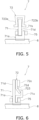
FIG. 5 is a schematic diagram of an attenuation mechanism according to the modification and another modification. -
FIG. 6 is a schematic diagram of an attenuation mechanism according to yet another modification. -
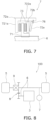
FIG. 7 is a schematic diagram of an attenuation mechanism according to further yet another modification. -
FIG. 8 is a block diagram of a power transmission system according to still further yet another modification. - A power transmission system according to a preferred embodiment of the present invention will be explained with reference to the attached drawings.
- As shown in
FIG. 1 , apower transmission system 100 is applied to a hybrid car. Thepower transmission system 100 includes anengine 1, aclutch 2, anelectric motor 3, a transmission 4 (exemplary gearbox), adrive wheel 5, atransmission shaft 6 and anattenuation mechanism 7. It should be noted that thepower transmission system 100 does not include any clutch between theelectric motor 3 and thedrive wheel 5. - The
electric motor 3 operates as a drive source. Theengine 1 may operate as a drive source generating electricity for theelectric motor 3 or may operate as a drive source for driving thedrive wheel 5. In other words, the hybrid car, to which thepower transmission system 100 according to the present preferred embodiment is applied, may be of any of a series type, a parallel type and a split type. - The
clutch 2 is disposed between theengine 1 and theelectric motor 3. The clutch 2 transmits a torque between theengine 1 and theelectric motor 3, while being capable of blocking transmission of the torque therebetween. Thetransmission 4 is disposed between theelectric motor 3 and thedrive wheel 5. Thetransmission 4 transmits rotation of theelectric motor 3 to thedrive wheel 5, while the rotation is increased or reduced in speed. - The
transmission shaft 6 transmits the torque between theelectric motor 3 and thedrive wheel 5. Thetransmission shaft 6 includes, for instance, a driveshaft. Alternatively, thetransmission shaft 6 may include a propeller shaft. Yet alternatively, thetransmission shaft 6 is not limited to a shaft transmitting the torque between the respective members, and is conceptualized as encompassing not only the shaft but also other members, for instance, a member disposed in a gearbox or reducer (the transmission 4) so as to transmit a torque. - The
attenuation mechanism 7 is attached to thetransmission shaft 6. For example, theattenuation mechanism 7 is attached to the driveshaft. It should be noted that when thetransmission shaft 6 includes the propeller shaft, theattenuation mechanism 7 may be attached to the propeller shaft. Alternatively, theattenuation mechanism 7 may be attached to the member disposed in the gearbox or reducer (the transmission 4) so as to transmit a torque. - The
attenuation mechanism 7 is disposed between theelectric motor 3 and thedrive wheel 5. Detailedly, theattenuation mechanism 7 is disposed between thetransmission 4 and thedrive wheel 5. - When fluctuations in torque inputted to the
attenuation mechanism 7 from thedrive wheel 5 has a predetermined value or greater, theattenuation mechanism 7 is configured to attenuate the torque fluctuations. On the other hand, when fluctuations in torque inputted to theattenuation mechanism 7 from thedrive wheel 5 has less than the predetermined value, theattenuation mechanism 7 is configured not to attenuate the torque fluctuations. - As shown in
FIG. 2 , theattenuation mechanism 7 includes asupport member 71, aninertia member 72 andfriction materials 73. Thesupport member 71 is attached to thetransmission shaft 6, and is unitarily rotated therewith. For example, thesupport member 71 is attached to thetransmission shaft 6 by rivet coupling, key coupling or so forth. Preferably, thesupport member 71 is integrally attached to thetransmission shaft 6. - The
inertia member 72 is disposed to be rotatable relatively to thetransmission shaft 6. Additionally, theinertia member 72 is engaged by friction with thesupport member 71. Detailedly, theinertia member 72 is engaged by friction with thesupport member 71 through thefriction materials 73. For example, thefriction materials 73 are attached to thesupport member 71. A pair of thefriction materials 73 each having an annular shape is attached to the both surfaces of thesupport member 71 so as to interpose the outer peripheral end of thesupport member 71 therebetween. - The
inertia member 72 is attached to thesupport member 71 so as to interpose therein thesupport member 71 to which the pair offriction materials 73 is attached. Detailedly, theinertia member 72 includes afirst inertia portion 72a and asecond inertia portion 72b. Additionally, the first andsecond inertia portions support member 71 to which the pair offriction materials 73 is attached. The first andsecond inertia portions rivet 74 attached to the outer peripheral ends thereof. - The
first inertia portion 72a includes anelastic portion 723a, while thesecond inertia portion 72b includes anelastic portion 723b. Theelastic portions support member 71 through thefriction materials 73, while being elastically deformed. In other words, theinertia member 72 is urged toward thesupport member 71 by the elastic force thereof so as to interpose thesupport member 71 therein. Because of this, it is possible to omit installation of an urging member for urging the first andsecond inertia portions support member 71. - In the
attenuation mechanism 7 configured as described above, when fluctuations in torque inputted thereto from thedrive wheel 5 do not have the predetermined value or greater, theinertia member 72 is unitarily rotated with thesupport member 71 while being engaged by friction therewith. - On the other hand, when fluctuations in torque inputted thereto from the
drive wheel 5 has the predetermined value or greater, theinertia member 72 is rotated relatively to thesupport member 71 while making contact by friction therewith. In other words, theinertia member 72 is rotated relatively to thesupport member 71, while friction resistances are applied thereto from thefriction materials 73. At this time, torque fluctuations are attenuated by an attenuation force of friction between theinertia member 72 and thesupport member 71. It should be noted that in the present preferred embodiment, thesupport member 71 and theinertia member 72 are engaged by friction with each other through thefriction materials 73 without making direct contact with each other. Thus, theattenuation mechanism 7 includes thefriction materials 73. Therefore, a friction coefficient can be easily adjusted and can be enhanced in stability. - One preferred embodiment of the present invention has been explained above. However, the present invention is not limited to the aforementioned preferred embodiment, and a variety of changes can be made without departing from the gist of the present invention.
- In the aforementioned preferred embodiment, the
attenuation mechanism 7 is disposed between thetransmission 4 and thedrive wheel 5. However, the layout of theattenuation mechanism 7 is not limited to this. For example, as shown inFIG. 3 , theattenuation mechanism 7 may be disposed between theelectric motor 3 and thetransmission 4. Detailedly, theattenuation mechanism 7 may be attached to an input shaft of thetransmission 4. It should be noted that the input shaft of thetransmission 4 is part of thetransmission shaft 6. Alternatively as shown inFIG. 4 , theattenuation mechanism 7 may be attached to a member that is disposed in the gearbox or reducer (the transmission 4) so as to transmit a torque. - In the aforementioned preferred embodiment, the
support member 71 of theattenuation mechanism 7 is formed by a single plate. However, the configuration of thesupport member 71 is not limited to this. For example, as shown inFIG. 5 , thesupport member 71 may be composed of two or more members. Detailedly, thesupport member 71 includes anattachment hub 71a and aplate portion 71b. Theplate portion 71b is attached to aflange portion 71d of theattachment hub 71a by, for instance, at least onerivet 75. - In the aforementioned preferred embodiment, the
inertia member 72 is engaged by friction with thesupport member 71 through thefriction materials 73. However, the configuration that theinertia member 72 is engaged by friction with thesupport member 71 is not limited to this. For example, as shown inFIG. 5 , theinertia member 72 may be engaged by friction with thesupport member 71, while making direct contact therewith. According to this configuration, it is possible to omit installation of the friction materials. - On the other hand, the
inertia member 72 includes theelastic portions elastic portions support member 71 while being elastically deformed. In other words, theinertia member 72 is urged toward thesupport member 71 by the elastic force thereof so as to interpose thesupport member 71 therein. Because of this, it is possible to omit installation of an urging member for urging theinertia member 72 toward thesupport member 71 and installation of a member for supporting the urging member. - In the aforementioned preferred embodiment, the
inertia member 72 interposes thesupport member 71 therein. However, the interposing configuration between theinertia member 72 and thesupport member 71 is not limited to this. For example, as shown inFIG. 6 , thesupport member 71 may interpose theinertia member 72 therein. In this case, for instance, thesupport member 71 includes theattachment hub 71a and aclamp portion 71c. Theattachment hub 71a is attached to thetransmission shaft 6. Theclamp portion 71c is attached to theflange portion 71d of theattachment hub 71a by the at least onerivet 75. Theclamp portion 71c interposes and holds theinertia member 72 together with theattachment hub 71a therebetween. According to this configuration, theinertia member 72 can be simplified in structure. Hence, the inertia amount can be easily adjusted, and can be easily increased as well. - Additionally, the
inertia member 72 includes aninertia body 72c and adisc spring plate 72d. Theinertia body 72c is attached to the outer peripheral end of thedisc spring plate 72d. Detailedly, the inner peripheral end of thedisc spring plate 72d functions as a disc spring, and is interposed between theclamp portion 71c and theflange portion 71d of theattachment hub 71a, while being compressed therebetween. In other words, the inner peripheral end of thedisc spring plate 72d forms the aforementionedelastic portion 723, and presses thesupport member 71 while being elastically deformed. According to this configuration, it is possible to omit installation of an urging member for urging theinertia member 72 toward thesupport member 71. - Additionally, the outer peripheral end of the
flange portion 71d of thesupport member 71 and that of thedisc spring plate 72d are engaged by friction with each other. Thus, a frictionally engaged part between thesupport member 71 and theinertia member 72 is disposed radially outside theelastic portion 723. According to this configuration, the frictionally engaged part can be made large in area. Hence, theelastic portion 723 can be reduced in elastic force required for engagement by friction. As a result, abrasion can be inhibited in the frictionally engaged part, and occurrence of slip can be prevented therein when engagement by friction is intended. Additionally, thesupport member 71 and theinertia member 72 are engaged by friction while making direct contact with each other. Hence, it is possible to omit installation of a friction material. - In the aforementioned preferred embodiment, the
inertia member 72 is urged against thesupport member 71 by the elastic force thereof. However, the urging configuration between theinertia member 72 and thesupport member 71 is not limited to this. For example, as shown inFIG. 7 , theattenuation mechanism 7 may further include an urgingmember 72e. The urgingmember 72e is, for instance, a disc spring. The urgingmember 72e urges theinertia member 72 and thesupport member 71 so as to make the both approach each other. - Detailedly, the
inertia member 72 includes the first andsecond inertia portions support member 71 therebetween. The urgingmember 72e urges the first andsecond inertia portions member 72e urges the first andsecond inertia portions support member 71. As a result, thesupport member 71, to which thefriction materials 73 are attached, can be interposed at the outer peripheral end thereof between the first andsecond inertia portions first inertia portion 72a includes adisc portion 721a and acylindrical portion 722a axially extending from the outer peripheral end of thedisc portion 721a. Additionally, a retainingring 76 is attached to the inner peripheral surface of thecylindrical portion 722a of thefirst inertia portion 72a. The retainingring 76 restricts axial movement of the urging member (disc spring) 72e. - According to this configuration, the
attenuation mechanism 7 includes the urgingmember 72e provided as a discrete member. Hence, it is possible to easily adjust an urging force applied in urge for making theinertia member 72 and thesupport member 71 approach each other. Besides, minute setting of the urging force is made easy. - In the aforementioned preferred embodiment, the power transmission system according to the present invention has been applied to the hybrid car. However, the power transmission system according to the present invention is applicable to an electric car as well. For example, as shown in
FIG. 8 , thepower transmission system 100 applied to the electric car includes theelectric motor 3, areducer 8, adifferential gear 9, thedrive wheel 5, thetransmission shaft 6 and theattenuation mechanism 7. It should be noted that the configurations of theelectric motor 3, thedrive wheel 5, thetransmission shaft 6 and theattenuation mechanism 7 are similar to those in the aforementioned preferred embodiment. Hence, the detailed explanation thereof will be hereinafter omitted. - The
attenuation mechanism 7 is disposed between thereducer 8 and thedrive wheel 5. Detailedly, theattenuation mechanism 7 is disposed between thedifferential gear 9 and thedrive wheel 5. It should be noted that theattenuation mechanism 7 may be disposed between theelectric motor 3 and thereducer 8. -
- 1: Engine
- 2: Clutch
- 3: Electric motor
- 4: Transmission
- 5: Drive wheel
- 6: Transmission shaft
- 7: Attenuation mechanism
- 8: Reducer
- 9: Differential gear
- 71: Support member
- 71a: Hub
- 71b: Plate portion
- 71c: Clamp portion
- 72d: Flange portion
- 72: Inertia member
- 72a: First inertia portion
- 72b: Second inertia portion
- 72c: Inertia body
- 72d: Disc spring plate
- 72e: Urging member
- 721a: Disc portion
- 722a: Cylindrical portion
- 723a: Elastic portion
- 723b: Elastic portion
- 73: Friction materials
- 74: Rivet
- 75: Rivet
- 100: Power transmission system
Claims (13)
- A power transmission system (100) comprising:an electric motor (3) for operating as a drive source;a drive wheel (5);a transmission shaft (6) transmitting a torque between the electric motor (3) and the drive wheel (5); andan attenuation mechanism (7) disposed between the electric motor (3) and the drive wheel (5), the attenuation mechanism (7) being attached to the transmission shaft (6), whereinthe attenuation mechanism (7) includes
a support member (71) fixed to the transmission shaft (6), and characterized in that an inertia member (72) is disposed to be rotatable relatively to the transmission shaft (6), the inertia member (72) being engaged by friction with the support member (71),wherein the support member (71) and the inertia member (72) are arranged on the transmission shaft (6) at a circumference thereof, wherein the attenuation mechanism (7) is configured such that when fluctuations in torque inputted to the attenuation mechanism (7) from the drive wheel (5) do not have a predetermined value or greater, the inertia member (72) is unitarily rotated with the support member (71) while being engaged by friction therewith; and when fluctuations in torque inputted to the attenuation mechanism (7) from the drive wheel (72) has the predetermined value or greater, the inertia member (72) is rotated relatively to the support member (71) while making contact by friction therewith. - The power transmission system (100) according to claim 1, further comprising:
a gearbox or reducer (8) disposed between the electric motor (3) and the drive wheel (5). - The power transmission system (100) according to claim 2, wherein the attenuation mechanism (7) is disposed between the drive wheel (5) and the gearbox or reducer (8).
- The power transmission system (100) according to claim 2, wherein the attenuation mechanism (7) is disposed between the electric motor (3) and the gearbox or reducer (8).
- The power transmission system (100) according to any of claims 1 to 4, whereinthe transmission shaft (6) includes a driveshaft, andthe attenuation mechanism (7) is attached to the driveshaft.
- The power transmission system (100) according to any of claims 1 to 4, whereinthe transmission shaft (6) includes a propeller shaft, andthe attenuation mechanism (7) is attached to the propeller shaft.
- The power transmission system (100) according to any of claims 1 to 6, whereinthe attenuation mechanism (7) further includes a friction material (73) attached to the support member (71) or the inertia member (72), andthe inertia member (72) is engaged by friction with the support member (71) through the friction material (73).
- The power transmission system (100) according to any of claims 1 to 6, wherein the inertia member (72) is engaged by friction with the support member (71) while making direct contact therewith.
- The power transmission system (100) according to any of claims 1 to 8, wherein the attenuation mechanism (7) further includes urging means for urging the inertia member (72) and the support member (71) so as to make the inertia member (72) and the support member (71) approach each other.
- The power transmission system (100) according to claim 9, wherein the attenuation mechanism (7) includes an urging member (72e) as the urging means, the urging member (72e) being provided separately from the inertia member (72) and the support member (71).
- The power transmission system (100) according to claim 9, wherein one of the inertia member (72) and the support member (71) includes an elastic portion (723a, 723b) as the urging means, the elastic portion (723a, 723b) pressing the other of the inertia member (72) and the support member (71) while being elastically deformed.
- The power transmission system (100) according to any of claims 9 to 11, wherein a frictionally engaged part between the inertia member (72) and the support member (71) is disposed radially outside the urging means.
- The power transmission system (100) according to any of claims 1 to 12, wherein the support member (71) includes an attachment hub (71a) and a clamp portion (71c), the attachment hub (71a) being attached to the transmission shaft (6), the clamp portion (71c) being attached to the attachment hub (71a), the clamp portion (71c) interposing and holding the inertia member (72) together with the attachment hub (71a) therebetween.
Applications Claiming Priority (1)
| Application Number | Priority Date | Filing Date | Title |
|---|---|---|---|
| JP2018133814A JP7458697B2 (en) | 2018-07-17 | 2018-07-17 | Power transmission system and damping mechanism |
Publications (3)
| Publication Number | Publication Date |
|---|---|
| EP3597961A1 EP3597961A1 (en) | 2020-01-22 |
| EP3597961B1 true EP3597961B1 (en) | 2024-07-10 |
| EP3597961C0 EP3597961C0 (en) | 2024-07-10 |
Family
ID=66770299
Family Applications (1)
| Application Number | Title | Priority Date | Filing Date |
|---|---|---|---|
| EP19178346.3A Active EP3597961B1 (en) | 2018-07-17 | 2019-06-05 | Power transmission system and attenuation mechanism |
Country Status (4)
| Country | Link |
|---|---|
| US (1) | US10745015B2 (en) |
| EP (1) | EP3597961B1 (en) |
| JP (1) | JP7458697B2 (en) |
| CN (1) | CN110722971B (en) |
Citations (4)
| Publication number | Priority date | Publication date | Assignee | Title |
|---|---|---|---|---|
| US20070278029A1 (en) * | 2006-06-02 | 2007-12-06 | Toyota Jidosha Kabushiki Kaisha | Hybrid drive system |
| EP2353912A1 (en) * | 2008-12-01 | 2011-08-10 | Honda Motor Co., Ltd. | Power transmitting device for hybrid vehicle |
| US20130193816A1 (en) * | 2012-01-30 | 2013-08-01 | Mikio Iwase | Vehicle drive device |
| US20160068153A1 (en) * | 2014-09-05 | 2016-03-10 | Ford Global Technologies, Llc | Clutch and electric machine control for driveline damping |
Family Cites Families (20)
| Publication number | Priority date | Publication date | Assignee | Title |
|---|---|---|---|---|
| US2152710A (en) | 1935-05-07 | 1939-04-04 | Daimler Benz Ag | Mechanism for absorbing torsional oscillations of shafts |
| PL281327A1 (en) * | 1989-09-06 | 1991-03-11 | Samochodow Osobowych Zaklad Sp | Main shock absorber of torsional vibrations in a clutch disk for motor vehicles |
| JPH0636934U (en) * | 1992-10-22 | 1994-05-17 | 三菱自動車工業株式会社 | Power transmission device |
| JP4239102B2 (en) * | 2005-07-05 | 2009-03-18 | アイシン・エィ・ダブリュ株式会社 | Hybrid vehicle drive system |
| CN101652563B (en) * | 2006-12-20 | 2012-02-08 | 维斯塔斯风力系统有限公司 | Use of torsional damping device and a wind turbine comprising same |
| JP2008195207A (en) * | 2007-02-13 | 2008-08-28 | Toyota Motor Corp | Drive device for hybrid vehicle |
| JP2010038312A (en) * | 2008-08-07 | 2010-02-18 | Aisin Seiki Co Ltd | Damper device |
| CN102105723B (en) | 2008-10-30 | 2013-03-27 | 爱信艾达工业株式会社 | Damper having torque limiter function |
| JP5585377B2 (en) | 2010-10-20 | 2014-09-10 | トヨタ自動車株式会社 | Damper device with torque limiter mechanism |
| EP2672141A4 (en) * | 2011-02-04 | 2014-12-17 | Toyota Motor Co Ltd | TORSION VIBRATION DAMPING DEVICE |
| CN103298637B (en) * | 2011-02-08 | 2016-03-30 | 本田技研工业株式会社 | The actuating device of motor vehicle driven by mixed power |
| JP2013148124A (en) | 2012-01-17 | 2013-08-01 | Toyota Motor Corp | Twist vibration attenuation mechanism of power transmission device |
| JP5394531B2 (en) | 2012-04-17 | 2014-01-22 | 株式会社エクセディ | Electric vehicle power transmission device |
| JP5712998B2 (en) * | 2012-12-26 | 2015-05-07 | トヨタ自動車株式会社 | Vehicle control device |
| JP2014181785A (en) | 2013-03-21 | 2014-09-29 | Toyota Motor Corp | Torsional vibration attenuation device |
| JP5669878B2 (en) * | 2013-03-25 | 2015-02-18 | トヨタ自動車株式会社 | Power transmission device for hybrid vehicle |
| JP6318746B2 (en) * | 2014-03-19 | 2018-05-09 | アイシン精機株式会社 | Damper device |
| US10316886B2 (en) * | 2015-05-11 | 2019-06-11 | Honda Motor Co., Ltd. | Damper device |
| JP6663760B2 (en) | 2016-03-18 | 2020-03-13 | 株式会社エクセディ | Torque converter |
| JP6679359B2 (en) | 2016-03-18 | 2020-04-15 | 株式会社エクセディ | A spring assembly and a damper device including the spring assembly. |
-
2018
- 2018-07-17 JP JP2018133814A patent/JP7458697B2/en active Active
-
2019
- 2019-05-15 US US16/413,428 patent/US10745015B2/en active Active
- 2019-06-05 EP EP19178346.3A patent/EP3597961B1/en active Active
- 2019-07-05 CN CN201910604319.8A patent/CN110722971B/en active Active
Patent Citations (4)
| Publication number | Priority date | Publication date | Assignee | Title |
|---|---|---|---|---|
| US20070278029A1 (en) * | 2006-06-02 | 2007-12-06 | Toyota Jidosha Kabushiki Kaisha | Hybrid drive system |
| EP2353912A1 (en) * | 2008-12-01 | 2011-08-10 | Honda Motor Co., Ltd. | Power transmitting device for hybrid vehicle |
| US20130193816A1 (en) * | 2012-01-30 | 2013-08-01 | Mikio Iwase | Vehicle drive device |
| US20160068153A1 (en) * | 2014-09-05 | 2016-03-10 | Ford Global Technologies, Llc | Clutch and electric machine control for driveline damping |
Also Published As
| Publication number | Publication date |
|---|---|
| CN110722971B (en) | 2024-05-14 |
| CN110722971A (en) | 2020-01-24 |
| EP3597961A1 (en) | 2020-01-22 |
| US10745015B2 (en) | 2020-08-18 |
| JP2020011553A (en) | 2020-01-23 |
| EP3597961C0 (en) | 2024-07-10 |
| JP7458697B2 (en) | 2024-04-01 |
| US20200023851A1 (en) | 2020-01-23 |
Similar Documents
| Publication | Publication Date | Title |
|---|---|---|
| US6026940A (en) | Lockup clutch with a compensation flywheel mass at the torsional vibration damper | |
| US4790419A (en) | Clutch with damper type flywheel | |
| JP5223999B2 (en) | Torsional vibration damping device | |
| EP2821669B2 (en) | Vibration reduction device | |
| EP0650563B1 (en) | Dual mass flywheel | |
| GB2309283A (en) | Torsional vibration damper | |
| CN107002815A (en) | Dual mass flywheel with one-piece hub flange | |
| US5918713A (en) | Wet friction plate, wet power transmitting and interrupting mechanism, wet clutch and lockup clutch | |
| JP2003013992A (en) | Damper unit with torque limiter | |
| US7500416B2 (en) | Vibration filter for a transmission with automatic, continuous or discontinuous, gearchange, especially for a motor vehicle | |
| US20200248779A1 (en) | Damper device | |
| JPH0141848B2 (en) | ||
| CN112145577A (en) | Torque transmission device equipped with torque limiter | |
| US7726449B2 (en) | Damper assembly with torque limiter | |
| EP2657567B1 (en) | Torsional vibration attenuation apparatus | |
| CN212338025U (en) | Torque limiters for drive trains, hybrid drive trains and hybrid vehicles | |
| EP3597961B1 (en) | Power transmission system and attenuation mechanism | |
| CN215444918U (en) | Torque damping device and hybrid vehicle | |
| CN111795114A (en) | Flywheel Assembly and Drivetrain | |
| US20210079988A1 (en) | Hybrid module with impact torque limiter | |
| US20200292028A1 (en) | Damper device | |
| US20210129653A1 (en) | Drive system | |
| JP4244438B2 (en) | Torque fluctuation absorber | |
| CN221779919U (en) | Torque limiting damper | |
| CN111108304A (en) | Torque transmitting device, torsional damper and related assembly |
Legal Events
| Date | Code | Title | Description |
|---|---|---|---|
| PUAI | Public reference made under article 153(3) epc to a published international application that has entered the european phase |
Free format text: ORIGINAL CODE: 0009012 |
|
| STAA | Information on the status of an ep patent application or granted ep patent |
Free format text: STATUS: THE APPLICATION HAS BEEN PUBLISHED |
|
| AK | Designated contracting states |
Kind code of ref document: A1 Designated state(s): AL AT BE BG CH CY CZ DE DK EE ES FI FR GB GR HR HU IE IS IT LI LT LU LV MC MK MT NL NO PL PT RO RS SE SI SK SM TR |
|
| AX | Request for extension of the european patent |
Extension state: BA ME |
|
| STAA | Information on the status of an ep patent application or granted ep patent |
Free format text: STATUS: REQUEST FOR EXAMINATION WAS MADE |
|
| 17P | Request for examination filed |
Effective date: 20200702 |
|
| RBV | Designated contracting states (corrected) |
Designated state(s): AL AT BE BG CH CY CZ DE DK EE ES FI FR GB GR HR HU IE IS IT LI LT LU LV MC MK MT NL NO PL PT RO RS SE SI SK SM TR |
|
| STAA | Information on the status of an ep patent application or granted ep patent |
Free format text: STATUS: EXAMINATION IS IN PROGRESS |
|
| 17Q | First examination report despatched |
Effective date: 20200828 |
|
| GRAP | Despatch of communication of intention to grant a patent |
Free format text: ORIGINAL CODE: EPIDOSNIGR1 |
|
| STAA | Information on the status of an ep patent application or granted ep patent |
Free format text: STATUS: GRANT OF PATENT IS INTENDED |
|
| INTG | Intention to grant announced |
Effective date: 20240306 |
|
| GRAS | Grant fee paid |
Free format text: ORIGINAL CODE: EPIDOSNIGR3 |
|
| GRAA | (expected) grant |
Free format text: ORIGINAL CODE: 0009210 |
|
| STAA | Information on the status of an ep patent application or granted ep patent |
Free format text: STATUS: THE PATENT HAS BEEN GRANTED |
|
| AK | Designated contracting states |
Kind code of ref document: B1 Designated state(s): AL AT BE BG CH CY CZ DE DK EE ES FI FR GB GR HR HU IE IS IT LI LT LU LV MC MK MT NL NO PL PT RO RS SE SI SK SM TR |
|
| REG | Reference to a national code |
Ref country code: CH Ref legal event code: EP |
|
| REG | Reference to a national code |
Ref country code: DE Ref legal event code: R096 Ref document number: 602019054883 Country of ref document: DE |
|
| U01 | Request for unitary effect filed |
Effective date: 20240710 |
|
| U07 | Unitary effect registered |
Designated state(s): AT BE BG DE DK EE FI FR IT LT LU LV MT NL PT SE SI Effective date: 20240716 |
|
| PG25 | Lapsed in a contracting state [announced via postgrant information from national office to epo] |
Ref country code: NO Free format text: LAPSE BECAUSE OF FAILURE TO SUBMIT A TRANSLATION OF THE DESCRIPTION OR TO PAY THE FEE WITHIN THE PRESCRIBED TIME-LIMIT Effective date: 20241010 |
|
| PG25 | Lapsed in a contracting state [announced via postgrant information from national office to epo] |
Ref country code: GR Free format text: LAPSE BECAUSE OF FAILURE TO SUBMIT A TRANSLATION OF THE DESCRIPTION OR TO PAY THE FEE WITHIN THE PRESCRIBED TIME-LIMIT Effective date: 20241011 Ref country code: PL Free format text: LAPSE BECAUSE OF FAILURE TO SUBMIT A TRANSLATION OF THE DESCRIPTION OR TO PAY THE FEE WITHIN THE PRESCRIBED TIME-LIMIT Effective date: 20240710 |
|
| PG25 | Lapsed in a contracting state [announced via postgrant information from national office to epo] |
Ref country code: IS Free format text: LAPSE BECAUSE OF FAILURE TO SUBMIT A TRANSLATION OF THE DESCRIPTION OR TO PAY THE FEE WITHIN THE PRESCRIBED TIME-LIMIT Effective date: 20241110 |
|
| PG25 | Lapsed in a contracting state [announced via postgrant information from national office to epo] |
Ref country code: HR Free format text: LAPSE BECAUSE OF FAILURE TO SUBMIT A TRANSLATION OF THE DESCRIPTION OR TO PAY THE FEE WITHIN THE PRESCRIBED TIME-LIMIT Effective date: 20240710 |
|
| PG25 | Lapsed in a contracting state [announced via postgrant information from national office to epo] |
Ref country code: ES Free format text: LAPSE BECAUSE OF FAILURE TO SUBMIT A TRANSLATION OF THE DESCRIPTION OR TO PAY THE FEE WITHIN THE PRESCRIBED TIME-LIMIT Effective date: 20240710 Ref country code: RS Free format text: LAPSE BECAUSE OF FAILURE TO SUBMIT A TRANSLATION OF THE DESCRIPTION OR TO PAY THE FEE WITHIN THE PRESCRIBED TIME-LIMIT Effective date: 20241010 |
|
| PG25 | Lapsed in a contracting state [announced via postgrant information from national office to epo] |
Ref country code: RS Free format text: LAPSE BECAUSE OF FAILURE TO SUBMIT A TRANSLATION OF THE DESCRIPTION OR TO PAY THE FEE WITHIN THE PRESCRIBED TIME-LIMIT Effective date: 20241010 Ref country code: PL Free format text: LAPSE BECAUSE OF FAILURE TO SUBMIT A TRANSLATION OF THE DESCRIPTION OR TO PAY THE FEE WITHIN THE PRESCRIBED TIME-LIMIT Effective date: 20240710 Ref country code: NO Free format text: LAPSE BECAUSE OF FAILURE TO SUBMIT A TRANSLATION OF THE DESCRIPTION OR TO PAY THE FEE WITHIN THE PRESCRIBED TIME-LIMIT Effective date: 20241010 Ref country code: IS Free format text: LAPSE BECAUSE OF FAILURE TO SUBMIT A TRANSLATION OF THE DESCRIPTION OR TO PAY THE FEE WITHIN THE PRESCRIBED TIME-LIMIT Effective date: 20241110 Ref country code: HR Free format text: LAPSE BECAUSE OF FAILURE TO SUBMIT A TRANSLATION OF THE DESCRIPTION OR TO PAY THE FEE WITHIN THE PRESCRIBED TIME-LIMIT Effective date: 20240710 Ref country code: GR Free format text: LAPSE BECAUSE OF FAILURE TO SUBMIT A TRANSLATION OF THE DESCRIPTION OR TO PAY THE FEE WITHIN THE PRESCRIBED TIME-LIMIT Effective date: 20241011 Ref country code: ES Free format text: LAPSE BECAUSE OF FAILURE TO SUBMIT A TRANSLATION OF THE DESCRIPTION OR TO PAY THE FEE WITHIN THE PRESCRIBED TIME-LIMIT Effective date: 20240710 |
|
| PG25 | Lapsed in a contracting state [announced via postgrant information from national office to epo] |
Ref country code: SM Free format text: LAPSE BECAUSE OF FAILURE TO SUBMIT A TRANSLATION OF THE DESCRIPTION OR TO PAY THE FEE WITHIN THE PRESCRIBED TIME-LIMIT Effective date: 20240710 |
|
| PG25 | Lapsed in a contracting state [announced via postgrant information from national office to epo] |
Ref country code: CZ Free format text: LAPSE BECAUSE OF FAILURE TO SUBMIT A TRANSLATION OF THE DESCRIPTION OR TO PAY THE FEE WITHIN THE PRESCRIBED TIME-LIMIT Effective date: 20240710 |
|
| PG25 | Lapsed in a contracting state [announced via postgrant information from national office to epo] |
Ref country code: SK Free format text: LAPSE BECAUSE OF FAILURE TO SUBMIT A TRANSLATION OF THE DESCRIPTION OR TO PAY THE FEE WITHIN THE PRESCRIBED TIME-LIMIT Effective date: 20240710 |
|
| PLBE | No opposition filed within time limit |
Free format text: ORIGINAL CODE: 0009261 |
|
| STAA | Information on the status of an ep patent application or granted ep patent |
Free format text: STATUS: NO OPPOSITION FILED WITHIN TIME LIMIT |
|
| 26N | No opposition filed |
Effective date: 20250411 |
|
| U20 | Renewal fee for the european patent with unitary effect paid |
Year of fee payment: 7 Effective date: 20250509 |
|
| PGFP | Annual fee paid to national office [announced via postgrant information from national office to epo] |
Ref country code: GB Payment date: 20250501 Year of fee payment: 7 |
|
| REG | Reference to a national code |
Ref country code: CH Ref legal event code: H13 Free format text: ST27 STATUS EVENT CODE: U-0-0-H10-H13 (AS PROVIDED BY THE NATIONAL OFFICE) Effective date: 20260127 |
|
| PG25 | Lapsed in a contracting state [announced via postgrant information from national office to epo] |
Ref country code: MC Free format text: LAPSE BECAUSE OF FAILURE TO SUBMIT A TRANSLATION OF THE DESCRIPTION OR TO PAY THE FEE WITHIN THE PRESCRIBED TIME-LIMIT Effective date: 20240710 |
|
| PG25 | Lapsed in a contracting state [announced via postgrant information from national office to epo] |
Ref country code: IE Free format text: LAPSE BECAUSE OF NON-PAYMENT OF DUE FEES Effective date: 20250605 |
|
| PG25 | Lapsed in a contracting state [announced via postgrant information from national office to epo] |
Ref country code: RO Free format text: LAPSE BECAUSE OF FAILURE TO SUBMIT A TRANSLATION OF THE DESCRIPTION OR TO PAY THE FEE WITHIN THE PRESCRIBED TIME-LIMIT Effective date: 20240710 |
|
| PG25 | Lapsed in a contracting state [announced via postgrant information from national office to epo] |
Ref country code: CH Free format text: LAPSE BECAUSE OF NON-PAYMENT OF DUE FEES Effective date: 20250630 |