EP3597920B1 - Rotor pair for a compressor block of a screw machine - Google Patents
Rotor pair for a compressor block of a screw machine Download PDFInfo
- Publication number
- EP3597920B1 EP3597920B1 EP19190907.6A EP19190907A EP3597920B1 EP 3597920 B1 EP3597920 B1 EP 3597920B1 EP 19190907 A EP19190907 A EP 19190907A EP 3597920 B1 EP3597920 B1 EP 3597920B1
- Authority
- EP
- European Patent Office
- Prior art keywords
- rotor
- tooth
- secondary rotor
- profile
- main
- Prior art date
- Legal status (The legal status is an assumption and is not a legal conclusion. Google has not performed a legal analysis and makes no representation as to the accuracy of the status listed.)
- Active
Links
- 230000006835 compression Effects 0.000 claims description 30
- 238000007906 compression Methods 0.000 claims description 30
- 238000013461 design Methods 0.000 claims description 21
- 239000012530 fluid Substances 0.000 claims description 8
- IJGRMHOSHXDMSA-UHFFFAOYSA-N Atomic nitrogen Chemical compound N#N IJGRMHOSHXDMSA-UHFFFAOYSA-N 0.000 claims description 6
- 230000007423 decrease Effects 0.000 claims description 5
- 239000001307 helium Substances 0.000 claims description 3
- 229910052734 helium Inorganic materials 0.000 claims description 3
- SWQJXJOGLNCZEY-UHFFFAOYSA-N helium atom Chemical compound [He] SWQJXJOGLNCZEY-UHFFFAOYSA-N 0.000 claims description 3
- 239000011261 inert gas Substances 0.000 claims description 3
- 229910052757 nitrogen Inorganic materials 0.000 claims description 3
- 230000009471 action Effects 0.000 description 38
- 230000000694 effects Effects 0.000 description 14
- 239000007789 gas Substances 0.000 description 13
- 238000005457 optimization Methods 0.000 description 13
- 238000000034 method Methods 0.000 description 11
- 241001050985 Disco Species 0.000 description 8
- 238000010276 construction Methods 0.000 description 8
- 238000004519 manufacturing process Methods 0.000 description 8
- 230000002349 favourable effect Effects 0.000 description 7
- 230000008901 benefit Effects 0.000 description 6
- 230000002093 peripheral effect Effects 0.000 description 5
- 238000005452 bending Methods 0.000 description 3
- 238000006073 displacement reaction Methods 0.000 description 3
- 238000005516 engineering process Methods 0.000 description 3
- 238000000227 grinding Methods 0.000 description 3
- 210000003128 head Anatomy 0.000 description 3
- 230000006872 improvement Effects 0.000 description 3
- 238000005056 compaction Methods 0.000 description 2
- 238000004590 computer program Methods 0.000 description 2
- 238000005520 cutting process Methods 0.000 description 2
- 230000001419 dependent effect Effects 0.000 description 2
- 238000011161 development Methods 0.000 description 2
- 238000009826 distribution Methods 0.000 description 2
- 210000000887 face Anatomy 0.000 description 2
- 210000001061 forehead Anatomy 0.000 description 2
- 230000003993 interaction Effects 0.000 description 2
- 239000000463 material Substances 0.000 description 2
- 238000003801 milling Methods 0.000 description 2
- 230000008569 process Effects 0.000 description 2
- 238000004378 air conditioning Methods 0.000 description 1
- 238000013459 approach Methods 0.000 description 1
- 238000004364 calculation method Methods 0.000 description 1
- 230000008859 change Effects 0.000 description 1
- 230000008094 contradictory effect Effects 0.000 description 1
- 230000006866 deterioration Effects 0.000 description 1
- 238000010586 diagram Methods 0.000 description 1
- 238000002474 experimental method Methods 0.000 description 1
- 238000009434 installation Methods 0.000 description 1
- 238000003754 machining Methods 0.000 description 1
- 230000000644 propagated effect Effects 0.000 description 1
- 230000009467 reduction Effects 0.000 description 1
- 239000003507 refrigerant Substances 0.000 description 1
- 238000005057 refrigeration Methods 0.000 description 1
- 238000007789 sealing Methods 0.000 description 1
- 230000007704 transition Effects 0.000 description 1
Images


Classifications
-
- F—MECHANICAL ENGINEERING; LIGHTING; HEATING; WEAPONS; BLASTING
- F04—POSITIVE - DISPLACEMENT MACHINES FOR LIQUIDS; PUMPS FOR LIQUIDS OR ELASTIC FLUIDS
- F04C—ROTARY-PISTON, OR OSCILLATING-PISTON, POSITIVE-DISPLACEMENT MACHINES FOR LIQUIDS; ROTARY-PISTON, OR OSCILLATING-PISTON, POSITIVE-DISPLACEMENT PUMPS
- F04C18/00—Rotary-piston pumps specially adapted for elastic fluids
- F04C18/08—Rotary-piston pumps specially adapted for elastic fluids of intermeshing-engagement type, i.e. with engagement of co-operating members similar to that of toothed gearing
- F04C18/082—Details specially related to intermeshing engagement type pumps
- F04C18/084—Toothed wheels
-
- F—MECHANICAL ENGINEERING; LIGHTING; HEATING; WEAPONS; BLASTING
- F01—MACHINES OR ENGINES IN GENERAL; ENGINE PLANTS IN GENERAL; STEAM ENGINES
- F01C—ROTARY-PISTON OR OSCILLATING-PISTON MACHINES OR ENGINES
- F01C1/00—Rotary-piston machines or engines
- F01C1/08—Rotary-piston machines or engines of intermeshing engagement type, i.e. with engagement of co- operating members similar to that of toothed gearing
- F01C1/082—Details specially related to intermeshing engagement type machines or engines
- F01C1/084—Toothed wheels
-
- F—MECHANICAL ENGINEERING; LIGHTING; HEATING; WEAPONS; BLASTING
- F01—MACHINES OR ENGINES IN GENERAL; ENGINE PLANTS IN GENERAL; STEAM ENGINES
- F01C—ROTARY-PISTON OR OSCILLATING-PISTON MACHINES OR ENGINES
- F01C1/00—Rotary-piston machines or engines
- F01C1/08—Rotary-piston machines or engines of intermeshing engagement type, i.e. with engagement of co- operating members similar to that of toothed gearing
- F01C1/12—Rotary-piston machines or engines of intermeshing engagement type, i.e. with engagement of co- operating members similar to that of toothed gearing of other than internal-axis type
- F01C1/14—Rotary-piston machines or engines of intermeshing engagement type, i.e. with engagement of co- operating members similar to that of toothed gearing of other than internal-axis type with toothed rotary pistons
- F01C1/16—Rotary-piston machines or engines of intermeshing engagement type, i.e. with engagement of co- operating members similar to that of toothed gearing of other than internal-axis type with toothed rotary pistons with helical teeth, e.g. chevron-shaped, screw type
-
- F—MECHANICAL ENGINEERING; LIGHTING; HEATING; WEAPONS; BLASTING
- F04—POSITIVE - DISPLACEMENT MACHINES FOR LIQUIDS; PUMPS FOR LIQUIDS OR ELASTIC FLUIDS
- F04C—ROTARY-PISTON, OR OSCILLATING-PISTON, POSITIVE-DISPLACEMENT MACHINES FOR LIQUIDS; ROTARY-PISTON, OR OSCILLATING-PISTON, POSITIVE-DISPLACEMENT PUMPS
- F04C18/00—Rotary-piston pumps specially adapted for elastic fluids
- F04C18/08—Rotary-piston pumps specially adapted for elastic fluids of intermeshing-engagement type, i.e. with engagement of co-operating members similar to that of toothed gearing
- F04C18/12—Rotary-piston pumps specially adapted for elastic fluids of intermeshing-engagement type, i.e. with engagement of co-operating members similar to that of toothed gearing of other than internal-axis type
- F04C18/14—Rotary-piston pumps specially adapted for elastic fluids of intermeshing-engagement type, i.e. with engagement of co-operating members similar to that of toothed gearing of other than internal-axis type with toothed rotary pistons
- F04C18/16—Rotary-piston pumps specially adapted for elastic fluids of intermeshing-engagement type, i.e. with engagement of co-operating members similar to that of toothed gearing of other than internal-axis type with toothed rotary pistons with helical teeth, e.g. chevron-shaped, screw type
-
- F—MECHANICAL ENGINEERING; LIGHTING; HEATING; WEAPONS; BLASTING
- F04—POSITIVE - DISPLACEMENT MACHINES FOR LIQUIDS; PUMPS FOR LIQUIDS OR ELASTIC FLUIDS
- F04C—ROTARY-PISTON, OR OSCILLATING-PISTON, POSITIVE-DISPLACEMENT MACHINES FOR LIQUIDS; ROTARY-PISTON, OR OSCILLATING-PISTON, POSITIVE-DISPLACEMENT PUMPS
- F04C18/00—Rotary-piston pumps specially adapted for elastic fluids
- F04C18/08—Rotary-piston pumps specially adapted for elastic fluids of intermeshing-engagement type, i.e. with engagement of co-operating members similar to that of toothed gearing
- F04C18/12—Rotary-piston pumps specially adapted for elastic fluids of intermeshing-engagement type, i.e. with engagement of co-operating members similar to that of toothed gearing of other than internal-axis type
- F04C18/14—Rotary-piston pumps specially adapted for elastic fluids of intermeshing-engagement type, i.e. with engagement of co-operating members similar to that of toothed gearing of other than internal-axis type with toothed rotary pistons
- F04C18/20—Rotary-piston pumps specially adapted for elastic fluids of intermeshing-engagement type, i.e. with engagement of co-operating members similar to that of toothed gearing of other than internal-axis type with toothed rotary pistons with dissimilar tooth forms
-
- F—MECHANICAL ENGINEERING; LIGHTING; HEATING; WEAPONS; BLASTING
- F04—POSITIVE - DISPLACEMENT MACHINES FOR LIQUIDS; PUMPS FOR LIQUIDS OR ELASTIC FLUIDS
- F04C—ROTARY-PISTON, OR OSCILLATING-PISTON, POSITIVE-DISPLACEMENT MACHINES FOR LIQUIDS; ROTARY-PISTON, OR OSCILLATING-PISTON, POSITIVE-DISPLACEMENT PUMPS
- F04C2240/00—Components
- F04C2240/20—Rotors
-
- F—MECHANICAL ENGINEERING; LIGHTING; HEATING; WEAPONS; BLASTING
- F04—POSITIVE - DISPLACEMENT MACHINES FOR LIQUIDS; PUMPS FOR LIQUIDS OR ELASTIC FLUIDS
- F04C—ROTARY-PISTON, OR OSCILLATING-PISTON, POSITIVE-DISPLACEMENT MACHINES FOR LIQUIDS; ROTARY-PISTON, OR OSCILLATING-PISTON, POSITIVE-DISPLACEMENT PUMPS
- F04C2240/00—Components
- F04C2240/30—Casings or housings
-
- F—MECHANICAL ENGINEERING; LIGHTING; HEATING; WEAPONS; BLASTING
- F04—POSITIVE - DISPLACEMENT MACHINES FOR LIQUIDS; PUMPS FOR LIQUIDS OR ELASTIC FLUIDS
- F04C—ROTARY-PISTON, OR OSCILLATING-PISTON, POSITIVE-DISPLACEMENT MACHINES FOR LIQUIDS; ROTARY-PISTON, OR OSCILLATING-PISTON, POSITIVE-DISPLACEMENT PUMPS
- F04C2240/00—Components
- F04C2240/60—Shafts
Definitions
- the invention relates to a pair of rotors for a compressor block of a screw machine, the pair of rotors consisting of a main rotor rotating about a first axis and an auxiliary rotor rotating about a second axis.
- the invention also relates to a compressor block with a corresponding pair of rotors.
- Screw machines whether as screw compressors or screw expanders, have been in practical use for several decades. Designed as screw compressors, they have replaced reciprocating compressors as compressors in many areas. With the principle of the interlocking pair of screws, not only gases can be compressed using a certain amount of work. The application as a vacuum pump also opens up the use of screw machines to achieve a vacuum. Finally, by passing pressurized gases through, a work output can also be generated the other way around, so that mechanical energy can also be obtained from pressurized gases using the principle of the screw machine.
- Screw machines generally have two shafts arranged parallel to one another, on the one hand a main rotor and on the other hand a secondary rotor. Main rotor and secondary rotor engage with each other with appropriate helical gearing. Between the teeth and a In the compressor housing, in which the main and secondary rotors are accommodated, a compression space (working chambers) is formed by the tooth gap volumes. Starting from an intake area, the working chamber is initially closed and then continuously reduced in volume as the rotation of the main and secondary rotors progresses, so that the medium is compressed. Finally, as the rotation progresses, the working chamber opens towards a pressure window and the medium is pushed out into the pressure window. This process of internal compression distinguishes screw machines designed as screw compressors from Roots blowers, which work without internal compression.
- Typical pressure ratios can range from 1.1 to 20 depending on the tooth count ratio, where pressure ratio is the ratio of discharge pressure to intake pressure.
- the compaction can take place in one or more stages.
- Final pressures that can be achieved can be in the range from 1.1 bar to 20 bar, for example. Insofar as reference is made to pressure data in "bar" at this point or later in the present application, such pressure data relate to absolute pressures.
- screw machines can also be used as compressors in different areas of technology.
- a particularly preferred area of application is the compression of gases, such as air or inert gases (helium, nitrogen, ).
- gases such as air or inert gases (helium, nitrogen, ).
- a screw machine for compressing refrigerants, for example for air conditioning systems or refrigeration applications, although this places different structural requirements in particular.
- fluid-injected compression in particular oil-injected compression, is usually used; but it is also possible to operate a screw machine according to the principle of dry compression.
- screw compressors are sometimes also referred to as screw blowers.
- the front section of the rotors in particular the front section of the secondary rotor, has a significant impact on energy efficiency.
- the face section of the auxiliary rotor In order to comply with the laws of gearing, the face section of the auxiliary rotor must find its equivalent in the face section of the main rotor.
- the profile of the rotor in a plane perpendicular to the axis of the rotor is referred to as a front section.
- Different types of face cut generation such as rotor-based or rack-based face cut generation methods, are now known from the prior art. Once you have decided on a specific method, a first draft face section is created in a first step. This is conventionally further optimized in several subsequent (revision) steps according to various criteria.
- a short profile gap length should be combined with a small (pressure side) blow hole.
- the two variables behave in opposite directions. This means that the smaller the blowhole is modeled, the larger the profile gap length will inevitably be. Conversely, the shorter the profile gap length, the larger the blowhole becomes. This is explained, for example, by Helpertz in his thesis “Method for the stochastic optimization of screw rotor profiles", Dortmund, 2003 on page 162.
- the requirement for a short profile gap length can be realized in a known manner with a flat profile with a correspondingly small relative profile depth of the auxiliary rotor. Whether a profile is rather flat (small profile depth) or deep (large profile depth) can be clearly quantified with the so-called "relative profile depth of the secondary rotor", which relates the difference between tip and root circle radius to the tip circle radius of the secondary rotor. je If the value is higher, the compressor block is more compact and has, for example, more delivery volume than a comparable compressor block with the same external dimensions.
- blow holes on the pressure side must not be made too large in order to minimize the backflow of already compressed medium into previous working chambers (i.e. in working chambers with lower pressure). Such backflows increase the energy expenditure for the total flow rate achieved and lead to an undesirable increase in the temperature and pressure level during compression, which reduces the overall efficiency.
- the area of the blow hole (blow hole area) can be kept small by making the head curves of the profiles small in the front section. Specifically, this can be caused by a strong curvature in the tip area of the leading tooth flank of the secondary rotor and in the tip area of the trailing tooth flank of the main rotor. However, the greater this curvature, the more likely it is that you will end up in production-related border areas, since this leads, for example, to high wear on profile milling cutters and profile grinding wheels in the production of the main rotor and secondary rotor.
- chamber gusset volume Another reason for efficiency-reducing internal leaks is the so-called chamber gusset volume, which can arise when the last working chamber (ie the working chamber in which the highest pressure prevails) is pushed out into the pressure window. From a certain angle of rotation of the rotors, the working chamber is no longer connected to the pressure window. A so-called chamber gusset volume remains between the two rotors and the pressure-side end wall of the housing.
- This chamber gusset volume is disadvantageous because the enclosed compressed medium can no longer be pushed out into the pressure window, and as the rotors turn further it is compressed even further, which leads to unnecessarily high power consumption (for overcompression), an unnecessarily high additional heat input, noise development and a reduction the service life, in particular of the roller bearings of the rotors.
- the specific performance is worsened by the fact that the portion enclosed in the chamber gusset volume returns to the suction side after overcompression and is therefore not available to the compressed air user.
- oil-injected compressors there is also incompressible oil in the chamber gusset and is being squeezed.
- Compact compressor blocks with a high utilization of construction volume are achieved through a large tooth gap volume, which in turn depends on the profile depth and the tooth thickness.
- the object of the present invention consists in specifying a pair of rotors for a compressor block of a screw machine, which is characterized by high operational reliability and reasonable production costs by very smooth running and a particular energy efficiency.
- the rotor geometry is essentially characterized by the shape of the face section as well as the rotor length and the angle of wrap, see “Method for the stochastic optimization of screw rotor profiles", dissertation by Markus Helpertz, Dortmund, 2003, pp. 11/12.
- the secondary rotor or main rotor has a predetermined, often different number of teeth of the same design per rotor.
- the outermost circle drawn through the axis C1 or C2 over the crests of the teeth is referred to as the tip circle.
- a base circle is defined in the face section by the points of the outer surface of the rotors closest to the axis.
- the ribs are called the teeth of the rotor.
- the grooves (or recesses) are accordingly referred to as tooth gaps.
- the area of the tooth at and above the root circle defines the tooth profile.
- the contour of the ribs defines the course of the tooth profile.
- Base points F1 and F2 and a vertex F5 are defined for the tooth profile.
- the vertex F5 or H5 is defined by the radially outermost point of the tooth profile. If the tooth profile has several points with the same maximum radial distance from the center point defined by the axis C1 or C2, i.e. the tooth profile follows an arc of a circle on the addendum circle at its radially outer end, then the vertex F5 lies exactly in the middle of this arc of a circle. A tooth gap is defined between two adjacent vertices F5.
- the points radially closest to the axis C1 or C2 between a tooth under consideration and the respective adjacent tooth define base points F1 and F2.
- the tooth profile at its lowest point follows the root circle in sections, the corresponding root point F1 or F2 then lies on half of this circular arc lying on the root circle .
- a pitch circle is defined for both the secondary rotor and the main rotor.
- screw machines as well as with gear wheels or friction wheels, there are always two circles in the front section of the toothing, which roll off each other during movement. These circles, on which in the present case the main rotor and the secondary rotor roll against each other, are referred to as respective pitch circles.
- the pitch circle diameters of the main rotor and secondary rotor can be determined with the help of the center distance and the number of teeth ratio.
- the circumferential speeds of the main rotor and secondary rotor are identical on the pitch circles.
- tooth gap areas between the teeth and the respective addendum circle KK are defined, namely tooth gap area A6 between the profile of the secondary rotor NR between two adjacent vertices F5 and the addendum circle KK 1 or an area A7 as a tooth gap area between the profile of the main rotor (HR) between two neighboring vertices H5 and the tip circle KK 2 .
- the tooth profile of the secondary rotor (but also of the main rotor) has a tooth flank that leads in the direction of rotation and a tooth flank that trails in the direction of rotation.
- the leading tooth flank is referred to below as F v
- the trailing tooth flank as F N .
- the trailing tooth flank F N In its section between tip circle and root circle, the trailing tooth flank F N forms a point at which the curvature of the course of the tooth profile changes. This point is referred to below as F8 and divides the trailing tooth flank F N into a convexly curved portion between F8 and the addendum circle and a concavely curved portion between the root circle and F8. Small-scale profile changes, such as sealing strips or other local profile changes, are not taken into account when considering the change in curvature described above.
- a wrap angle ⁇ is defined. This angle of wrap is the angle by which the face section is twisted from the suction-side to the pressure-side rotor face, see also the detailed explanations in connection with figure 8 .
- the main rotor has a rotor length L HR , which is defined as the distance from a suction-side main rotor rotor face to a pressure-side main rotor rotor face.
- the distance between the first axis C1 of the auxiliary rotor, which runs parallel to one another, and the second axis C2 of the main rotor is referred to below as the axis distance a.
- the length of the main rotor L HR corresponds to the length of the secondary rotor L NR , with the length of the secondary rotor also being understood as the distance between a suction-side secondary rotor rotor face and a pressure-side secondary rotor rotor face.
- a rotor length ratio L HR/ a is defined, i.e. a ratio of the rotor length of the main rotor to the center distance.
- the ratio L HR/ a is a measure for the axial dimensioning of the rotor profile.
- the line of action or the profile gap is created by the interaction of the main rotor and the secondary rotor with one another.
- the line of action is as follows: The tooth flanks of the main rotor and secondary rotor touch each other with backlash-free gearing depending on the rotational angle position of the rotors specific points. These points are called engagement points.
- the geometric location of all points of action is called the line of action and can already be calculated in two dimensions using the face section of the rotors, cf. Figure 7j .
- the line of action is divided into two sections in the face section view by the connecting line between the two centers C1 and C2, specifically into a (comparatively short) suction-side section and a (comparatively long) pressure-side section.
- the line of action can also be extended three-dimensionally and corresponds to the contact line of the main rotor and auxiliary rotor.
- the axial projection of the three-dimensional line of action onto the front section plane results in turn from Figure 7j illustrated two-dimensional line of action.
- the term "line of action” is used in the literature for both two-dimensional and three-dimensional considerations. In the following, unless otherwise stated, "line of action” is to be understood as meaning the two-dimensional line of action, ie the projection onto the face section.
- the profile contact gap is defined as follows: In the real compressor block of a screw machine, there is play between the two rotors when the main rotor and secondary rotor are installed axially apart.
- the gap between the main rotor and the slave rotor is called the profile engagement gap and is the locus of all points where the two paired rotors touch each other or are closest to each other.
- the profile engagement gap Through the profile engagement gap, the compressing and ejecting working chambers are connected to chambers that are still in contact with the suction side. The entire maximum pressure ratio is therefore present at the profile engagement gap. Already compressed working fluid is transported back to the suction side through the profile engagement gap and thus reduces the efficiency of the compression. Since the profile engagement gap would be the line of action in the case of backlash-free gearing, the profile engagement gap is also referred to as the “quasi line of action”.
- Blowholes between working chambers are created by rounding the tips of the teeth of the profile.
- certain pairs of teeth are known to be common in screw machines, for example a rotor pair in which the main rotor has 3 and the auxiliary rotor has 4 teeth or a rotor pair in which the main rotor has 4 teeth and the auxiliary rotor has 5 teeth or furthermore a rotor pair geometry in which the main rotor has 5 teeth and the secondary rotor has 6 teeth.
- Rotor pairs or screw machines with different tooth ratios may be used for different areas of application or purposes. For example, rotor pair arrangements with a tooth ratio of 4/5 (main rotor with 4 teeth, auxiliary rotor with 5 teeth) are considered a suitable pairing for oil-injected compression applications in moderate pressure ranges.
- the number of teeth or the number of teeth ratio specifies different types of rotor pairings and, as a result, also different types of screw machines, in particular screw compressors.
- the ratio of the center distance ⁇ of the first axis C1 to the second axis C2 and the addendum circle radius rk is 1 a rk 1 set so that a rk 1 is at least 1.636 and at most 1.8, preferably at most 1.733, with the main rotor preferably being designed with a wrap angle ⁇ HR for which 240° ⁇ HR ⁇ 360° applies, and with the following preferably applying for a rotor length ratio L HR/ a: 1.4 ⁇ L MR / a ⁇ 3.4 , where the rotor length ratio is formed from the ratio of the rotor length L HR of the main rotor and the center distance a and the rotor length L HR of the main rotor is formed by the distance between a suction-side main rotor rotor face and an opposite pressure-side main rotor rotor face.
- the ratio of the center distance a of the first axis C1 to the second axis C2 and the addendum circle radius rk is 1 a rk 1 set so that a rk 1 is at least 1.683 and at most 1.836, preferably at most 1.782, with the main rotor preferably being designed with a wrap angle ⁇ HR for which 240° ⁇ ⁇ HR ⁇ 360° applies, and with the following preferably applying for a rotor length ratio L HR/ a: 1.4 ⁇ L MR / a ⁇ 3.3 , where the rotor length ratio is formed from the ratio of the rotor length L HR of the main rotor and the center distance a and the rotor length L HR of the Main rotor is formed by the distance of a suction-side main rotor rotor face to an opposite pressure-side main rotor rotor face.
- the ratio of the center distance a of the first axis C1 to the second axis C2 and the addendum circle radius rk is 1 a rk 1 set so that a rk 1 at least 1.74, preferably at least 1.75 and at most 1.8, preferably at most 1.79, the main rotor preferably being designed with a wrap angle ⁇ HR for which 240° ⁇ HR ⁇ 360° applies, and where preferably for a rotor length ratio L HR/ a the following applies: 1.4 ⁇ L MR / a ⁇ 3.2 , where the rotor length ratio is formed from the ratio of the rotor length L HR of the main rotor and the center distance a and the rotor length L HR of the main rotor is formed by the distance between a suction-side main rotor rotor face and an opposite pressure-side main rotor rotor face.
- the values for the relative profile depth on the one hand and the ratio of the center distance to the tip circle radius of the secondary rotor on the other hand are in the specified advantageous ranges for the specified number of teeth ratios, then the basic requirements for a good secondary rotor profile or a good interaction of the secondary rotor profile and Main rotor profile created, in particular, this enables a particularly favorable ratio of blowhole area to profile gap length.
- the relative tread depth of the slave rotor is a measure of how deep the treads are cut. With increasing profile depth, for example, the utilization of construction volume increases, but at the expense of the flexural rigidity of the secondary rotor.
- the specified values for the rotor length ratio L HR/ a and the wrap angle ⁇ HR represent advantageous or expedient values for the specified number of teeth ratio in order to define an advantageous rotor pairing in the axial dimension.
- the aim is to combine a small blow hole with a short length of the profile engagement gap.
- the two parameters behave in opposite directions, ie the smaller the blow hole is modeled, the larger the length of the profile contact gap will inevitably be. Conversely, the shorter the length of the profile-engaging gap, the larger the blowhole becomes.
- a particularly favorable combination of the two parameters is achieved in the stressed areas. At the same time, a sufficiently high flexural rigidity of the secondary rotor is ensured.
- a further preferred embodiment provides that in a face section consideration between the considered tooth of the secondary rotor (NR) and the respectively adjacent tooth of the secondary rotor, base points F1 and F2 are defined on the root circle and on the radially outermost point of the tooth an apex F5, with F1, F2 and F5, a triangle D z is defined and in a radially outer area the tooth with its leading tooth flank F v formed between F5 and F2 has an area A1 and with its trailing tooth flank F N formed between F1 and F5 has an area A2 the triangle Dz protrudes and where 8 ⁇ A2/A1 ⁇ 60 is observed.
- the partial tooth surface A1 on the leading tooth flank F v of the secondary rotor has a significant influence on the blow hole surface.
- the partial tooth surface A2 on the trailing tooth flank F N of the auxiliary rotor has a significant influence on the length of the profile engagement gap, the chamber extension and the auxiliary rotor torque.
- the pair of rotors has a secondary rotor, in which, in a face section view, between the tooth of the secondary rotor (NR) under consideration and the respective adjacent tooth of the Sub-rotor base points F1 and F2 and at the radially outermost point of the tooth an apex F5 are defined, with a triangle Dz being defined by F1, F2 and F5 and with the leading tooth flank Fv formed between F5 and F2 in a radially outer region of the tooth with an area A1 protrudes beyond the triangle D z and recedes in a radially inner region with respect to the triangle D z with an area A3 and where 7.0 ⁇ A3/A1 ⁇ 35 is observed.
- NR secondary rotor
- base points F1 and F2 are defined between the tooth of the secondary rotor (NR) under consideration and the respective adjacent tooth of the secondary rotor (NR) and a vertex F5 is defined at the radially outermost point of the tooth are, wherein a triangle D z is defined by F1, F2 and F5 and wherein the leading tooth flank F v formed between F5 and F2 protrudes in a radially outer region of the tooth with an area A1 over the triangle D z , the tooth itself having a has a cross-sectional area A0 delimited by the arc of a circle B running between F1 and F2 around the center point defined by the axis C1, and where 0.5% ⁇ A1/A0 ⁇ 4.5% is observed.
- Figures 7d as well as 7e.
- a further preferred embodiment provides that in a face section consideration between the considered tooth of the secondary rotor (NR) and the respectively adjacent tooth of the secondary rotor (NR) base points F1 and F2 and at the radially outermost point of the tooth an apex F5 are defined, with the between F1 and F2 arcs B running around the center point defined by the axis C1 defines a tooth pitch angle ⁇ corresponding to 360°/number of teeth of the secondary rotor (NR), with a point F11 being defined on half the arc B between F1 and F2, with a dated
- the offset angle is preferably always positive, ie always the offset in the direction of the direction of rotation is given and not against.
- the tooth of the secondary rotor is curved towards the direction of rotation of the secondary rotor.
- the offset should remain within the range specified as advantageous in order to enable a favorable compromise between the blowhole area, the shape of the line of action, the length and shape of the profile engagement gap, the auxiliary rotor torque, the bending stiffness of the rotors and the chamber extension into the pressure window.
- trailing tooth flank F N of a tooth of the secondary rotor (NR) formed between F1 and F5 has a convex length portion of at least 45% to at most 95% in a face section consideration.
- the secondary rotor is preferably designed in such a way that, in a front section view, the radial ray R drawn from the axis C1 of the secondary rotor (NR) through F5 divides the tooth profile into a surface portion A5 assigned to the leading tooth flank F v and a surface portion A4 assigned to the trailing tooth flank F N and where 5 ⁇ A 4 / A 5 ⁇ 14 is complied with. It should be pointed out once again at this point that the tooth profile is delimited radially inwards towards the axis C1 by the root circle FK1 .
- the radial ray R divides the tooth profile in such a way that two disjoint surface portions with a total surface portion A5, which are assigned to the leading tooth flank Fv , arise, cf. Figure 7g . If the vertex F5 were to be offset in relation to the leading tooth flank in such a way that the radial ray R not only touches the leading tooth flank F v but intersects it at two points, then there are again two of the leading tooth flank associated disjunctive areas defined with a total area A5.
- the area portion A4 assigned to the trailing tooth flank F N is then limited on the one hand by the radial ray R and in sections, namely between the two intersection points of the leading tooth flank F v with the radial ray R, on the other hand also by the leading tooth flank F v .
- a further preferred embodiment has a pair of rotors which is characterized in that the main rotor HR is designed with a wrap angle ⁇ HR for which the following applies: 290° ⁇ HR ⁇ 360°, preferably 320° ⁇ HR ⁇ 360°.
- the pressure window area can be made larger with the same built-in volume ratio.
- the axial extent of the working chamber to be pushed out, the so-called profile pocket depth is also shortened as a result. This reduces the exhaust throttling losses, especially at higher speeds, and thus enables better specific power.
- an angle of wrap that is too large has a negative effect on the construction volume and leads to larger rotors.
- ⁇ l denotes a profile gap length factor, whereby the length of the profile engagement gap of a tooth gap is set in relation to the profile depth PT 1 .
- a measure for the length of the profile engagement gap can thus be defined regardless of the size of the screw machine.
- the lower the numerical value of the key figure ⁇ l the shorter the profile gap of a tooth pitch with the same profile depth and thus the lower the leakage volume flow back to the suction side.
- the objective of combining a small blow hole on the pressure side with a short profile gap results from the factor ⁇ l ⁇ ⁇ Bl .
- the two key figures behave in opposite directions.
- main rotor (HR) and secondary rotor (NR) are designed and coordinated in such a way that dry compression with a pressure ratio ⁇ of up to 3, in particular with a pressure ratio ⁇ of greater than 1 and up to 3 , is achievable, the pressure ratio being the ratio of the compression end pressure to the intake pressure.
- a further preferred embodiment provides a pair of rotors such that the main rotor (HR) is designed to be operable with a peripheral speed in a range of 20 to 100 m/s in relation to a tip circle KK 2 .
- a further embodiment has a pair of rotors which is characterized in that for a diameter ratio defined by the ratio of the tip circle radii of the main rotor (HR) and the secondary rotor (NR).
- D v dk 2
- the aim is to combine a small blow hole with a short length of the profile engagement gap.
- the two parameters behave in opposite directions, ie the smaller the blow hole is modeled, the larger the length of the profile contact gap will inevitably be. Conversely, the shorter the length of the profile-engaging gap, the larger the blowhole becomes.
- a particularly favorable combination of the two parameters is achieved in the stressed areas. At the same time, a sufficiently high flexural rigidity of the secondary rotor is ensured.
- a further preferred embodiment provides that in a face section consideration between the considered tooth of the secondary rotor (NR) and the respectively adjacent tooth of the secondary rotor (NR) base points F1 and F2 are defined at the root circle and at the radially outermost point of the tooth an apex F5, where a triangle D z is defined by F1, F2 and F5 and in a radially outer area the tooth with its leading tooth flank F v formed between F5 and F2 has an area A1 and with its trailing tooth flank F N formed between F1 and F5 has a Area A2 protrudes beyond the triangle D z and where 6 ⁇ A2/A1 ⁇ 15 is observed.
- the partial tooth surface A1 on the leading tooth flank F v of the secondary rotor has a significant influence on the blow hole surface.
- the partial tooth surface A2 on the trailing tooth flank F N of the auxiliary rotor has a significant influence on the length of the profile engagement gap, the chamber extension and the auxiliary rotor torque.
- There is an advantageous range for the tooth surface area ratio A2/A1 which offers a good compromise between the length of the Profile engagement gap on the one hand and blow hole on the other hand allows.
- the pair of rotors has a secondary rotor in which, in a face section view, base points F1 and F2 are defined between the tooth of the secondary rotor (NR) under consideration and the respective adjacent tooth of the secondary rotor (NR) and an apex F5 is defined at the radially outermost point of the tooth
- a triangle D z is defined by F1, F2 and F5 and the leading tooth flank F v formed between F5 and F2 protrudes with an area A1 over the triangle D z in a radially outer area of the tooth and in a radially inner area compared to the triangle D z with an area A3 and where 9.0 ⁇ A3/A1 ⁇ 18 is observed.
- base points F1 and F2 are defined between the tooth of the secondary rotor (NR) under consideration and the respective adjacent tooth of the secondary rotor (NR) and a vertex F5 is defined at the radially outermost point of the tooth are, wherein a triangle D z is defined by F1, F2 and F5 and wherein the leading tooth flank F v formed between F5 and F2 protrudes in a radially outer region of the tooth with an area A1 over the triangle D z , the tooth itself having a has a cross-sectional area A0 delimited by the arc of a circle B running between F1 and F2 around the center point defined by the axis C1, and where 1.5% ⁇ A1/A0 ⁇ 3.5% is observed.
- the offset angle is preferably always positive, ie the offset is always in the direction of the direction of rotation and not in the opposite direction.
- the tooth of the secondary rotor is curved towards the direction of rotation of the secondary rotor.
- the offset should remain within the range specified as advantageous in order to enable a favorable compromise between the blowhole area, the shape of the line of action, the length and shape of the profile engagement gap, the auxiliary rotor torque, the bending stiffness of the rotors and the chamber extension into the pressure window.
- trailing tooth flank F N formed between F1 and F5 of a tooth of the secondary rotor (NR) has a convex length portion of at least 55% to at most 95% in a face section consideration.
- the auxiliary rotor is preferably designed in such a way that, in a face section view, the radial ray R drawn from the axis C1 of the auxiliary rotor (NR) through F5 divides the tooth profile into a surface portion A5 assigned to the leading tooth flank F v and a surface portion A4 assigned to the trailing tooth flank F N and where 4 ⁇ A4/A5 ⁇ 9 is complied with. It should be pointed out once again at this point that the tooth profile is delimited radially inwards towards the axis C1 by the root circle FK1 .
- the radial ray R divides the tooth profile in such a way that two disjoint surface portions with a total surface portion A5, which are assigned to the leading tooth flank Fv , arise, cf. Figure 7g . If the vertex F5 were offset towards the leading tooth flank in such a way that the radial ray R not only touches the leading tooth flank F v but intersects it at two points, then two disjoint surface portions assigned to the leading tooth flank are defined with a total surface portion A5.
- the area portion A4 associated with the trailing tooth flank F N is then delimited in sections by the radial ray R, namely between the two intersection points of the leading tooth flank F v with the radial ray R, and also by the leading tooth flank F v .
- a further preferred embodiment has a pair of rotors which is characterized in that the main rotor HR is designed with a wrap angle ⁇ HR for which the following applies: 320° ⁇ HR ⁇ 360°, preferably 330° ⁇ HR ⁇ 360°.
- the pressure window area can be made larger with the same built-in volume ratio.
- the axial extent of the working chamber to be pushed out, the so-called profile pocket depth is also shortened as a result. This reduces the exhaust throttling losses, especially at higher speeds, and thus enables better specific power.
- an angle of wrap that is too large has a negative effect on the construction volume and leads to larger rotors.
- ⁇ l denotes a profile gap length factor, whereby the length of the profile engagement gap of a tooth gap is set in relation to the profile depth PT 1 . This allows a measure of the length of the profile engagement gap to be defined, regardless of the size of the screw machine. The smaller the numerical value of the key figure ⁇ l , the shorter the profile gap with the same profile depth and thus the lower the leakage volume flow back to the suction side. The goal of combining a small blow hole on the pressure side with a short profile gap results from the factor ⁇ l * ⁇ Bl . As already mentioned, the two key figures behave in opposite directions.
- main rotor (HR) and secondary rotor (NR) are designed and coordinated with one another in such a way that dry compression with a pressure ratio of up to 5, in particular with a pressure ratio ⁇ of greater than 1 and up to 5, or alternatively a fluid-injected compression can be achieved with a pressure ratio of up to 16, in particular with a pressure ratio greater than 1 and up to 16, the pressure ratio designating the ratio of the compression end pressure to the intake pressure.
- a further preferred embodiment provides a pair of rotors such that in the case of dry compression, the main rotor, based on a tip circle KK 2 , has a peripheral speed in a range of 20 to 100 m/s and in the case of fluid-injected compression, the main rotor has a peripheral speed in a range of 5 to 50 m/s.
- a further embodiment has a pair of rotors which is characterized in that for a diameter ratio defined by the ratio of the tip circle radii of the main rotor (HR) and the secondary rotor (NR).
- the aim is to combine a small blow hole with a short length of the profile engagement gap.
- the two parameters behave in opposite directions, ie the smaller the blow hole is modeled, the larger the length of the profile contact gap will inevitably be. Conversely, the shorter the length of the profile-engaging gap, the larger the blowhole becomes.
- a particularly favorable combination of the two parameters is achieved in the stressed areas. At the same time, a sufficiently high flexural rigidity of the secondary rotor is ensured.
- a further preferred embodiment provides that in a face section consideration between the considered tooth of the secondary rotor (NR) and the respective adjacent tooth of the secondary rotor (NR) base points F1 and F2 at the root circle and at the radially outermost point of the tooth an apex F5 are defined, wherein a triangle D Z is defined by F1, F2 and F5 and wherein in a radially outer area the tooth with its leading tooth flank F v formed between F5 and F2 has an area A1 and with its trailing tooth flank formed between F1 and F5 F N protrudes with an area A2 over the triangle D z and where 4 ⁇ A2/A1 ⁇ 7 is observed.
- the partial tooth surface A1 on the leading tooth flank F v of the secondary rotor has a significant influence on the blow hole surface.
- the partial tooth surface A2 on the trailing tooth flank F N of the auxiliary rotor has a significant influence on the length of the profile engagement gap, the chamber extension and the auxiliary rotor torque.
- the pair of rotors has a secondary rotor in which, in a face section view, there are base points F1 and F2 between the tooth of the secondary rotor (NR) under consideration and the respective adjacent tooth of the secondary rotor (NR) and an apex F5 at the radially outermost point of the tooth are defined, with a triangle D z being defined by F1, F2 and F5 and with the leading tooth flank F V formed between F5 and F2 protruding in a radially outer area of the tooth with an area A1 over the triangle D Z and in a radially inner area Area opposite the triangle D Z with an area A3 recedes and where 8 ⁇ A3/A1 ⁇ 14 is maintained.
- base points F1 and F2 between the tooth of the secondary rotor (NR) under consideration and the respective adjacent tooth of the secondary rotor (NR) and an apex F5 at the radially outermost point of the tooth are defined, with a triangle D z being defined by F1, F2 and F5 and with the
- base points F1 and F2 are defined between the tooth of the secondary rotor (NR) under consideration and the respective adjacent tooth of the secondary rotor (NR) and a vertex F5 is defined at the radially outermost point of the tooth are, wherein a triangle D z is defined by F1, F2 and F5 and wherein the leading tooth flank F v formed between F5 and F2 protrudes in a radially outer region of the tooth with an area A1 over the triangle D z , the tooth itself having a has a cross-sectional area A0 bounded by the arc of a circle B running between F1 and F2 around the center point defined by the axis C1 and where 1.9% ⁇ A1/A0 ⁇ 3.2% is complied with.
- Figures 7d as well as 7e.
- the offset angle is preferably always positive, ie the offset is always in the direction of the direction of rotation and not in the opposite direction.
- the tooth of the secondary rotor is curved towards the direction of rotation of the secondary rotor.
- the offset should remain within the range specified as advantageous in order to enable a favorable compromise between the blow hole area, the shape of the line of action, the profile gap length and shape, the auxiliary rotor torque, the bending stiffness of the rotors and the chamber extension into the pressure window.
- a further preferred embodiment has a pair of rotors which is characterized in that the main rotor HR is designed with a wrap angle ⁇ HR for which the following applies: 320° ⁇ ⁇ HR ⁇ 360°, preferably 330° ⁇ ⁇ HR ⁇ 360°
- ⁇ HR wrap angle
- the pressure window area can be made larger with the same built-in volume ratio.
- this also shortens the axial extension of the to be pushed out Working chamber, the so-called profile pocket depth. This reduces the exhaust throttling losses, especially at higher speeds, and thus enables better specific power.
- an angle of wrap that is too large has a negative effect on the construction volume and leads to larger rotors.
- ⁇ l denotes a profile gap length factor, whereby the length of the profile engagement gap of a tooth gap is set in relation to the profile depth PT 1 . This allows a measure of the length of the profile engagement gap to be defined, regardless of the size of the screw machine. The smaller the numerical value of the key figure ⁇ l , the shorter the profile gap with the same profile depth and thus the lower the leakage volume flow back to the suction side. The objective of combining a small blow hole on the pressure side with a short profile gap results from the factor ⁇ l ⁇ ⁇ Bl . As already mentioned, the two key figures behave in opposite directions.
- main rotor (HR) and secondary rotor (NR) are designed and coordinated with one another in such a way that dry compression with a pressure ratio of up to 5, in particular with a pressure ratio ⁇ of greater than 1 and up to 5, or alternatively, a fluid-injected compression with a pressure ratio of up to 20, in particular with a pressure ratio ⁇ of greater than 1 and up to 20, can be achieved where the pressure ratio is the ratio of the compression end pressure to the intake pressure.
- a further preferred embodiment provides a pair of rotors such that the main rotor (HR) based on a tip circle KK 2 in the case of dry compression with a peripheral speed in a range of 20 to 100 m / s and in the case of fluid-injected compression with a peripheral speed is designed to be operable in a range from 5 to 50 m/s.
- a further embodiment has a pair of rotors which is characterized in that for a diameter ratio defined by the ratio of the tip circle radii of the main rotor (HR) and the secondary rotor (NR).
- D v dk 2
- the teeth of the auxiliary rotor taper outwards in a cross-sectional view, i.e. all circular arcs running perpendicularly to a radial ray emanating from the center point defined by the axis C1 and drawn through the point F5 from the trailing tooth flank F N to the leading tooth flank F V starting from F1 to F2 in the sequence radially outward decrease (or at least remain the same in sections).
- the teeth of the secondary rotor are thus designed in such a way that there are no constrictions, ie the width of a tooth of the secondary rotor does not increase at any point, but instead decreases radially outwards or at most remains the same. This is considered useful in order to achieve a small blow hole on the pressure side with a nevertheless short profile engagement gap length.
- the face section design of the secondary rotor (NR) is such that the effective direction of the torque, which results from a reference pressure on the partial surface of the secondary rotor delimiting a working chamber, is directed counter to the direction of rotation of the secondary rotor.
- Such an end section design has the effect that the entire torque from the gas forces on the secondary rotor is directed counter to the direction of rotation of the secondary rotor. This achieves a defined flank contact between the trailing secondary rotor flank F N and the leading main rotor flank. This contributes to avoiding the problem of so-called rotor rattling, which can occur in unfavorable, in particular non-stationary, operating situations.
- Rotor rattling is understood to mean a leading and lagging of the secondary rotor about its axis of rotation superimposed on the uniform rotational movement, which is accompanied by a rapidly alternating impact of the trailing secondary rotor flanks on the leading main rotor flanks and then the leading secondary rotor flanks on the trailing main rotor flanks, etc.
- This problem occurs in particular when the moment from the gas forces together with other moments (eg from bearing friction) on the secondary rotor is undefined (eg close to zero), which is effectively avoided by the advantageous front section design.
- the main rotor (HR) and the secondary rotor (NR) are designed to convey air or inert gases, such as helium or nitrogen, and are matched to one another.
- the profile of a tooth of the secondary rotor is asymmetrically formed in a face section view with respect to the radial ray R drawn from the center point, which is defined by the axis C1, through the apex F5.
- the leading tooth flank and trailing tooth flank of each tooth are therefore asymmetrical in relation to one another.
- This asymmetrical design is already known per se for screw compressors. However, it makes a significant contribution to efficient compaction.
- a further preferred embodiment provides that a point C on the connecting section is viewed in a cross section C1 C2 is defined between the first axis C1 and the second axis C2, where the pitch circles WK 1 of the secondary rotor (NR) and WK 2 of the main rotor (HR) touch, that K5 is the intersection of the root circle FK 1 of the secondary rotor (NR) with the connecting section C1 C2 where r 1 measures the distance between K5 and C, and that K4 denotes the point of the suction-side part of the line of action furthest from the connecting line C1 C2 is spaced between C1 and C2, where r 2 measures the distance between K4 and C and where: 0.9 ⁇ right 1 right 2 ⁇ 0.875 ⁇ e.g 1 e.g 2 + 0.22 with z 1 : number of teeth on the secondary rotor (NR) and z 2 : number of teeth on the main rotor (HR).
- the pair of rotors is constructed and designed in such a way that the following applies for a rotor length ratio L HR/ a: 0.85 * e.g 1 / e.g 2 + 0.67 ⁇ L MR / a ⁇ 1.26 * e.g 1 / e.g 2 + 1:18 , preferred 0.89 * e.g 1 / e.g 2 + 0.94 ⁇ L MR / a ⁇ 1.05 * e.g 1 / e.g 2 + 1.22 , with z 1 : number of teeth in the secondary rotor (NR) and z 2 : number of teeth in the main rotor (HR), the rotor length ratio L HR/ a the ratio of Rotor length L HR indicates the center distance a and rotor length L HR is the distance from the suction-side main rotor rotor face to the pressure-side main rotor rotor face.
- the flexural rigidity of the rotors is sufficiently high so that the rotors do not deflect significantly during operation and the gaps (between the rotors or between the rotors and the compressor housing) can therefore be made relatively narrow without the risk of that under unfavorable operating conditions (high temperatures and/or high pressures) the rotors collide or collide in the compressor housing.
- Narrow gaps offer the advantage of low backflow and thus contribute to energy efficiency. At the same time, operational safety is guaranteed despite the small gap dimensions.
- a high flexural rigidity of the rotors is also advantageous in rotor production in order to comply with the high requirements for shape tolerances.
- the ratio of L HR/ a is dimensioned so large that the center distance a is not excessively large in relation to the rotor length L HR .
- This is advantageous because, as a consequence, the rotor diameter and, quite specifically, the end faces of the rotors are not excessively large.
- the gap lengths can be kept small; this reduces the backflow into the previous working chambers and this in turn improves energy efficiency.
- the axial forces resulting from the pressure-loaded, pressure-side end faces of the rotors can also be advantageously kept small through small-dimensioned end faces; these axial forces act on the rotors and in particular on the rotor bearings during operation. By minimizing these axial forces, the load on the (roller) bearings can be minimized or the bearings can be dimensioned smaller.
- the configuration of the tooth profile of the secondary rotor described above is relevant above all for a tooth number ratio of 3/4 or 4/5. With such a number of teeth ratio, the blow hole area can be reduced by complying with the condition given above. With a tooth number ratio of 5/6, however, an aforementioned point of contact or aforementioned points of intersection with the leading tooth flank F V does not appear to be desirable, since the teeth of the secondary rotor may then be too thin and consequently too flexible.
- a compressor block comprising a compressor housing and a pair of rotors as described above is claimed as being according to the invention, the pair of rotors comprising a main rotor HR and a secondary rotor NR, which are each rotatably mounted in the compressor housing.
- the compressor block is designed in such a way that the front section is designed in such a way that the working chamber formed between the tooth profiles of the main rotor (HR) and secondary rotor (NR) can be pushed out essentially completely into the pressure window.
- the front section design of the two rotors advantageously ensures that no chamber gusset volume forms between the two rotors when the working chamber is pushed out into the pressure window.
- the compression can take place particularly efficiently, since no backflow of already compressed medium takes place on the suction side, and herewith none additional heat input occurs.
- the entire compressed volume can be used by downstream compressed air consumers. Because overcompression is avoided, there are advantages in terms of energy efficiency, the smooth running of the compressor block and the service life of the rotor bearings. With oil-injected compressors, squeezing of the oil is prevented, thus improving the smooth running of the compressor, reducing the load on the rotor bearings and reducing the stress on the oil.
- a shaft end of the main rotor is guided out of the compressor housing and designed for connection to a drive, with both shaft ends of the secondary rotor preferably being completely accommodated within the compressor housing.
- Example 1 Example 2
- Example 3 Example 4 Number of teeth HR z 2 3 3 4 5 Number of teeth NR z 1 4 4 5 6 PTrel [-] 0.588 0.54 0.528 0.455 a/rk 1 [-] 1.66 1.72 1,764 1.78
- the profiles were created with the following center distances a: Example 1 Example 2
- Example 3 Example 4 Center distance a[mm] 127 111 This results in the following cross section main dimensions:
- Example 1 Example 2
- Example 3 Example 4 Dk 2 [mm] 191 186.1 186 154 Dk 1 [mm] 153 147.7 144 124.7 bw 2 [mm] 54.4 56.4 50.5 bw 1 [mm] 72.6 70.6 60.5
- Other main dimensions of the rotors Example 1
- Example 3 Example 4 Rotor length L HR [mm] 307 293 235.5
- Radial R 10 Radial ray R 10 has 2 points of intersection with the leading tooth flank F V - Area ratio A4/A5 [-] 7.5 10.1 5.5 - wrap angle ⁇ HR 334.7 degrees 330.3 330.3 ⁇ BI [%] 0.159 0.086 0.106 0.18 ⁇ BI* ⁇ l [%] 0.94 0.53 0.631 1,058
- Profile front section design with regard to chamber extension The working chamber can essentially be completely pushed out into the pressure window.
- Profile face section design with regard to secondary rotor torque The effective direction of the NR torque resulting from the gas forces is directed against the direction of rotation of the secondary rotor.
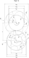
- the isentropic block efficiency compared to the prior art is for the second embodiment to 3/4 tooth number ratio in figure 5 illustrated. Two curves of the same pressure ratio are shown there.
- the pressure ratio actually shown is 2.0 (ratio of outlet pressure to inlet pressure).
- the isentropic block efficiency has been significantly improved compared to the values achievable with the prior art.
- the in the figures 5 and 6 The delivery quantity specified in each case corresponds to the delivery volume flow of the compressor block in relation to the suction condition.
- direction of rotation 24 of the secondary rotor and the necessarily resulting direction of rotation of the main rotor when operating as a compressor.
- the leading tooth flank F v and the trailing tooth flank F N are marked on a secondary rotor tooth.
- a tooth gap 23 is marked as representative of all tooth gaps of the secondary rotor.
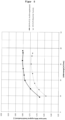
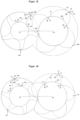
- the based on Figure 7a shown profile course of the leading tooth flank F v and the trailing tooth flank F N corresponds to the basis of figure 4 for a gear ratio of 5/6 explained embodiment.
- Figure 7b shows the tooth gap surfaces A6 and A7 as well as a side view of a blowhole in a cross-sectional view.
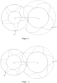
- the profile curves shown to explain the tooth gap areas A6 and A7 correspond to that for a tooth number ratio of 3/4 based on figure 1 illustrated embodiment.
- the coordinate system is spanned by the u-axis parallel to the front faces of the rotor along the pressure-side intersection edge 11.
- the blow hole on the pressure side lies in the coordinate system described and quite concretely in a plane perpendicular to the rotor end faces between the pressure side intersection edge 11 and a line of action point K2 of the part of the line of action on the pressure side.
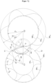
- the line of action 10 is divided into two sections by the connecting line between the two centers C1 and C2: the suction-side part of the line of action is shown below, the pressure-side part above the connecting line.
- K2 designates the point of the pressure-side part of the line of action 10 which is spaced farthest from the straight line through C1 and C2.
- the intersection of the tip circles of the two rotors creates an intersection edge 11 on the pressure side and an intersection edge 12 on the suction side
- Figure 7b is the pressure-side intersection edge 11 in one Forehead view shown as a point. The same applies to the representation of the suction-side intersection edge 12.
- the u-axis is parallel to the rotor faces and corresponds to the vector from the line of action point K2 to the pressure-side intersection edge 11 in a face section view.
- blow hole area A BI on the pressure side can be found in Figure 7k .
- Figure 7c shows a tooth of the secondary rotor with the concentric circular arcs B 25 , B 50 , B 75 running inside the rotor tooth around the center C1 with the associated radii r 25 , r 50 , r 75 and the associated arc lengths b 25 , b 50 , b 75 .
- the circular arcs B 25 , B 50 , B 75 are each delimited by the leading tooth flank F V and the trailing tooth flank F N .
- the based on Figure 7c shown profile course of the leading tooth flank F V and the trailing tooth flank F N corresponds to the basis of figure 4 for a gear ratio of 5/6 explained embodiment.
- Figure 7d shows base points F1 and F2 on the root circle and at the radially outermost point of the tooth an apex F5 in a face section view between the considered tooth of the secondary rotor and the respectively adjacent tooth of the secondary rotor. Furthermore, the triangle D Z defined by the points F1, F2 and F5 is shown.
- Figure 7d shows the following (tooth part) surfaces: Partial tooth area A1 corresponds to the area with which the tooth in question, with its leading tooth flank F V formed between F5 and F2, protrudes beyond the triangle D Z in a radially outer area.
- Partial tooth area A2 corresponds to the area with which the tooth under consideration with its trailing tooth flank F N formed between F5 and F1 protrudes beyond the triangle D Z in a radially outer area.
- Area A3 corresponds to the area with which the tooth in question, with its leading tooth flank formed between F5 and F2, recedes in relation to triangle D z .
- tooth pitch angle ⁇ corresponding to 360°/number of teeth of the secondary rotor.
- profile course of the leading tooth flank F v and the trailing tooth flank F N corresponds to the basis of figure 4 for a gear ratio of 5/6 explained embodiment.
- Figure 7e shows the cross-sectional area A0 of a tooth of the secondary rotor, which is delimited by the circular arc B running between F1 and F2 around the center point C1, in a cross-sectional view.
- the based on Figure 7e shown profile course of the leading tooth flank F V and the trailing tooth flank F N corresponds to the basis of figure 4 for a gear ratio of 5/6 explained embodiment.
- Figure 7f shows the offset angle ⁇ in a front section view. This is defined by the offset from point F11 to point F12 viewed in the direction of rotation of the auxiliary rotor.
- F11 is a point on half the circular arc B between F1 and F2 around the center C1 and therefore corresponds to the intersection of the bisector of the tooth pitch angle ⁇ with the circular arc B.
- Figure 7g shows the inflection point F8 on the trailing tooth flank F N of the secondary rotor, in which the curvature of the course of the tooth profile changes between the addendum and root circle, in a cross-sectional view.
- the trailing tooth flank F N of the auxiliary rotor is divided by point F8 into a substantially convexly curved portion between F8 and the apex F5 and a substantially concavely curved portion between F8 and the base point F1.
- Figure 7h shows two points of intersection of the radial ray R 10 from C1 to F10 with the leading tooth flank F v of the secondary rotor in a cross-sectional view, with point F10 designating that point on the leading tooth flank F v which lies on the addendum circle KK 1 with rk 1 and is furthest from F5 is spaced.
- the tooth flank follows a circular arc ARC 1 with radius rk 1 radially on the outside over a defined section around the center point of the auxiliary rotor defined by the axis C1.
- the profile curves of the leading tooth flank F v and the trailing tooth flank F N explained above correspond to the exemplary embodiment described for a tooth number ratio of 3/4 figure 1 .
- Figure 7i shows the tooth profile divided by the radial ray R drawn from C1 to F5 in a face section view.
- the tooth profile is divided into a surface portion A4 associated with the trailing tooth flank F N and a surface portion A5 associated with the leading tooth flank F v .
- the based on Figure 7i The profile curves of the leading tooth flank F V and the trailing tooth flank F N explained above correspond to the exemplary embodiment described for a tooth number ratio of 5/6 figure 4 .
- Figure 7j shows the line of action 10 between the main and auxiliary rotor and the two concentric circles around the point C with the radii r 1 and r 2 for describing the characteristic features of the course of the suction-side part of the line of action.
- the line of action 10 is divided into two sections by the connecting distance between the first axis C1 and the second axis C2: the suction-side part of the line of action is below, the pressure-side part is above the connecting distance C1 C2 shown.
- Point C is the point of contact of the pitch circle WK 1 of the secondary rotor with the pitch circle WK 2 of the main rotor.
- K4 designates the point of the suction-side part of the line of action which is farthest from the connecting section between C1 and C2.
- Radius r 1 is the distance between K5 and C, radius r 2 denotes the distance between K4 and C.
- Figure 7k shows a pressure-side blow hole area A Bl of a working chamber, specifically in a sectional view perpendicular to the rotor end faces.
- the delimitation of the blow hole area A Bl arises from the intersection line 27 of the imaginary flat surface described above with the leading side rotor flank F v , the intersection line 26 of the plane with the trailing HR flank and a straight section [K1 K3] of the pressure-side intersection edge 11.
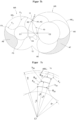
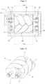
- figure 9 shows a schematic sectional view of a compressor block 19 comprising a housing 15 and mounted therein two rotors geared to one another in pairs, namely a main rotor HR and a secondary rotor NR.
- the main rotor HR and the secondary rotor NR are each rotatably mounted in the housing 15 via suitable bearings 16 .
- a drive power can be applied to a shaft 17 of the main rotor HR, for example with a motor (not shown) via a clutch 18 .
- the compressor block shown is an oil-injected screw compressor, in which the torque is transmitted between the main rotor HR and the secondary rotor NR directly via the rotor flanks. In contrast to With a dry screw compressor, touching of the rotor flanks can be avoided by means of a synchronization gear (not shown).
- an intake port for sucking in the medium to be compressed and an outlet for the compressed medium are also not shown.
- FIG 10 a main rotor HR interlocked with one another and a secondary rotor NR are also shown in a perspective view.
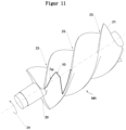
- figure 11 shows the spatial line of action 10 of exactly one tooth gap 23.
- the profile gap length l sp is the length of the spatial line of action of exactly one tooth gap 23. This corresponds accordingly to the profile gap length of exactly one tooth division.
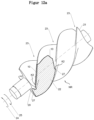
- the total torque from the gas forces on the secondary rotor is made up of the sum of the torque effects of the gas pressures in all working chambers on the sub-surfaces of the secondary rotor that delimit the respective working chambers.
- a partial surface (22) of the secondary rotor delimiting a working chamber is shown hatched as an example.
- Figure 12b shows the division of the in Figure 12a partial surface (22) delimiting a working chamber into an area (28) shown with dots and an area (29) shown with cross-hatching. Only the cross-hatched area (29) contributes to the torque.
- the partial surface (22) results from the specific face section design and the pitch of the secondary rotor.
- the pitch of the slave rotor refers to the pitch of the helical splines of the slave rotor.
- the three-dimensional line of action (10) which is also shown and delimits the partial surface is also defined by the design of the face section of the secondary rotor and the pitch.
- Partial surface (22) is also bounded by intersection line (27). Details of cutting line (27) have already been included in the figures 7b and 7k shown and described. The same applies to the line of action point K2.
- the effective direction of the torque that the gas pressure in the working chamber (or any reference pressure) causes on the partial surface of the secondary rotor delimiting the working chamber is determined by the design of the front section of the secondary rotor.
- the above-described advantageous front section design of the secondary rotor (NR) therefore leads to an effective direction (25) of the torque from the gas forces for each partial surface (22) of the secondary rotor that delimits a working chamber and thus for the entire secondary rotor, which is opposite to the direction of rotation (24) of the secondary rotor is directed, whereby the rotor clatter is effectively avoided.
- the illustrated exemplary embodiments prove that with the present invention a considerable increase in efficiency could be achieved for a pair of rotors used in screw machines, consisting of a main rotor and a secondary rotor with a corresponding profile geometry.
- profile profiles can also be generated using publicly accessible computer programs—as is well known to those skilled in the art.
- ScrewView software Another alternative software is the ScrewView software, which is also mentioned in the dissertation “Directed Evolutionary Algorithms” by Stefan Berlik, Dortmund 2006 (p. 173 f.).
- the ScrewView software is described in more detail on the website http://pi.informatik.unirisonen.de/Employees/berlik/projects/ in connection with the project "Method for designing dry-running rotary displacement machines”.
- a tooth with a trailing rotor flank F N and a leading rotor flank F v is specifically generated as follows:
- the section S1 to S2 results from a circular arc on the secondary rotor NR around the center C1, generated by the circular arc section T1 to T2 around the center C2 on the Main rotor HR.
- the section S2 to S3 results from an envelope curve to a trochoid, generated by arc section T2 to T3 around the center point M4 on the main rotor HR.
- the section S3 to S4 is surrounded by an arc of a circle defines the center point M1.
- the section S4 to S5 is defined by an arc of a circle around the center point M2.
- the section S5 to S6 is defined by an arc of a circle around the center point C1.
- the subsequent section S6 to S7 is specified by an arc of a circle around the center point M3.
- the section S7 to S1 is specified by an envelope curve to form a trochoid, generated by the circular arc section T7 to T1 around the center point M5 on the main rotor HR.
- the profile of the teeth of the main rotor HR is for the embodiment according to Figures 1 to 4 also based on the Figures 13 to 16 briefly explained below.
- the section T1-T2 results from an arc of a circle on the main rotor HR around the center point C2 on the main rotor HR.
- the section T2-T3 is defined by the circular arc on the main rotor HR around the center point M4.
- Section T3-T4 results from an envelope curve to a trochoid generated by section S3-S4 on slave rotor NR.
- Section T4-T5 is defined by an envelope curve to a trochoid generated by section S4-S5 on the secondary rotor.
- the section T5-T6 is defined by a circular arc around the center C2 generated by the circular arc section S5-S6 around the center C1 on the slave rotor NR.
- Section T6-T7 results from an envelope curve to form a trochoid, generated by section S6-S7 on secondary rotor NR.
- the section T7-T1 is defined by an arc of a circle around the center point M5.
- the profile curves of the secondary rotor NR and the main rotor HR are of course coordinated with one another and insofar as the envelope curves of a trochoid correspond to circular arc sections on the counter-rotor.
- a tangential transition from one section to the next is guaranteed.
- a general The procedure for calculating the profile of the counter-rotor is described, for example, in Helpertz's thesis, "Method for the stochastic optimization of screw rotor profiles", Dortmund, 2003, p. 60 et seq.
Description
Die Erfindung betrifft ein Rotorpaar für einen Verdichterblock einer Schraubenmaschine, wobei das Rotorpaar aus einem um eine erste Achse rotierenden Hauptrotor und einem um eine zweite Achse rotierenden Nebenrotor besteht nach den Merkmalen des Anspruchs 1, 9 oder 14. Weiterhin betrifft die Erfindung einen Verdichterblock mit einem entsprechenden Rotorpaar.The invention relates to a pair of rotors for a compressor block of a screw machine, the pair of rotors consisting of a main rotor rotating about a first axis and an auxiliary rotor rotating about a second axis. The invention also relates to a compressor block with a corresponding pair of rotors.
Schraubenmaschinen, sei es als Schraubenverdichter oder als Schraubenexpander, sind seit mehreren Jahrzehnten im praktischen Einsatz. Ausgestaltet als Schraubenverdichter haben sie in vielen Bereichen Hubkolbenverdichter als Verdichterverdrängt. Mit dem Prinzip des ineinandergreifenden Schraubenpaars lassen sich nicht nur Gase unter Aufwendung einer bestimmten Arbeitsleistung komprimieren. Die Anwendung als Vakuumpumpe eröffnet auch den Einsatz von Schraubenmaschinen zur Erzielung eines Vakuums. Schließlich kann durch das Hindurchleiten von unter Druck stehenden Gasen anders herum auch eine Arbeitsleistung erzeugt werden, so dass aus unter Druck stehenden Gasen mittels des Prinzips der Schraubenmaschine auch mechanische Energie gewonnen werden kann.Screw machines, whether as screw compressors or screw expanders, have been in practical use for several decades. Designed as screw compressors, they have replaced reciprocating compressors as compressors in many areas. With the principle of the interlocking pair of screws, not only gases can be compressed using a certain amount of work. The application as a vacuum pump also opens up the use of screw machines to achieve a vacuum. Finally, by passing pressurized gases through, a work output can also be generated the other way around, so that mechanical energy can also be obtained from pressurized gases using the principle of the screw machine.
Schraubenmaschinen weisen allgemein zwei parallel zueinander angeordnete Wellen auf, auf denen einerseits ein Hauptrotor und andererseits ein Nebenrotor sitzen. Hauptrotor und Nebenrotor greifen mit entsprechender schraubenförmiger Verzahnung ineinander. Zwischen den Verzahnungen und einem Verdichtergehäuse, in dem Haupt- und Nebenrotor aufgenommen sind, wird durch die Zahnlückenvolumina ein Verdichtungsraum (Arbeitskammern) gebildet. Ausgehend von einem Ansaugbereich wird mit fortschreitender Drehung von Haupt-und Nebenrotor die Arbeitskammer zunächst geschlossen und dann kontinuierlich im Volumen verringert, so dass eine Verdichtung des Mediums eintritt. Schließlich wird bei fortschreitender Drehung die Arbeitskammer zu einem Druckfenster hin geöffnet und das Medium in das Druckfenster ausgeschoben. Durch diesen Vorgang der inneren Verdichtung unterscheiden sich als Schraubenkompressoren ausgebildete Schraubenmaschinen von Rootsgebläsen, die ohne innere Verdichtung arbeiten.Screw machines generally have two shafts arranged parallel to one another, on the one hand a main rotor and on the other hand a secondary rotor. Main rotor and secondary rotor engage with each other with appropriate helical gearing. Between the teeth and a In the compressor housing, in which the main and secondary rotors are accommodated, a compression space (working chambers) is formed by the tooth gap volumes. Starting from an intake area, the working chamber is initially closed and then continuously reduced in volume as the rotation of the main and secondary rotors progresses, so that the medium is compressed. Finally, as the rotation progresses, the working chamber opens towards a pressure window and the medium is pushed out into the pressure window. This process of internal compression distinguishes screw machines designed as screw compressors from Roots blowers, which work without internal compression.
Je nach gefordertem Druckverhältnis (Verhältnis Ausgangsdruck zu Eingangsdruck) sind für eine effiziente Verdichtung unterschiedliche Zähne-Zahlverhältnisse sinnvoll.Depending on the required pressure ratio (ratio of outlet pressure to inlet pressure), different tooth number ratios make sense for efficient compression.
Typische Druckverhältnisse können je nach Zähne-Zahlverhältnis zwischen 1,1 und 20 liegen, wobei das Druckverhältnis das Verhältnis von Verdichtungsenddruck zu Ansaugdruck ist. Die Verdichtung kann ein- oder mehrstufig erfolgen. Erzielbare Enddrücke können beispielsweise im Bereich 1,1 bar bis 20 bar liegen. Soweit an dieser Stelle oder nachfolgend in der vorliegenden Anmeldung auf Druckangaben in "bar" Bezug genommen wird, so beziehen sich derartige Druckangaben jeweils auf Absolutdrücke.Typical pressure ratios can range from 1.1 to 20 depending on the tooth count ratio, where pressure ratio is the ratio of discharge pressure to intake pressure. The compaction can take place in one or more stages. Final pressures that can be achieved can be in the range from 1.1 bar to 20 bar, for example. Insofar as reference is made to pressure data in "bar" at this point or later in the present application, such pressure data relate to absolute pressures.
Schraubenmaschinen können neben der bereits erwähnten Funktion als Vakuumpumpe oder als Schraubenexpander auf unterschiedlichen Gebieten der Technik als Verdichter eingesetzt werden. Ein besonders bevorzugtes Anwendungsgebiet liegt bei der Verdichtung von Gasen, wie z.B. Luft oder inerten Gasen, (Helium, Stickstoff, ...). Es ist aber auch möglich, wenngleich dies im Speziellen baulich andere Anforderungen stellt, eine Schraubenmaschine zur Verdichtung von Kältemitteln, beispielsweise für Klimaanlagen oder Kälteanwendungen, einzusetzen. Bei der Verdichtung von Gasen gerade bei höheren Druckverhältnissen wird meist mit einer fluideingespritzten Verdichtung, insbesondere einer öleingespritzten Verdichtung gearbeitet; es ist aber auch möglich, eine Schraubenmaschine nach dem Prinzip der trockenen Verdichtung zu betreiben. Im Niederdruckbereich werden Schraubenverdichter gelegentlich auch als Schraubengebläse bezeichnet.In addition to the already mentioned function as a vacuum pump or as a screw expander, screw machines can also be used as compressors in different areas of technology. A particularly preferred area of application is the compression of gases, such as air or inert gases (helium, nitrogen, ...). However, it is also possible to use a screw machine for compressing refrigerants, for example for air conditioning systems or refrigeration applications, although this places different structural requirements in particular. When compressing gases, especially at higher pressure ratios, fluid-injected compression, in particular oil-injected compression, is usually used; but it is also possible to operate a screw machine according to the principle of dry compression. In the low-pressure range, screw compressors are sometimes also referred to as screw blowers.
Es sind in den vergangenen Jahrzehnten beträchtliche Erfolge hinsichtlich der Herstellbarkeit, der Zuverlässigkeit, der Laufruhe sowie der Effizienz von Schraubenmaschinen erzielt worden. Verbesserungen bzw. Optimierungen beziehen sich dabei häufig auf Optimierungen des Wirkungsgrades in Abhängigkeit von Zähnezahl, Umschlingungswinkel und Längen-/Durchmesserverhältnis der Rotoren. Die Hinzunahme der Stirnschnitte in den Optimierungsprozess findet man erst in jüngster Zeit.Considerable success has been achieved over the past decades in terms of manufacturability, reliability, smooth running and efficiency of screw machines. Improvements or optimizations often relate to optimization of the efficiency depending on the number of teeth, angle of contact and length/diameter ratio of the rotors. The addition of forehead cuts to the optimization process has only recently been found.
Versuche haben gezeigt, dass der Stirnschnitt der Rotoren, insbesondere der Stirnschnitt des Nebenrotors, einen wesentlichen Einfluss auf die Energieeffizienz hat. Zur Einhaltung der Verzahnungsgesetze muss der Stirnschnitt des Nebenrotors seine Entsprechung im Stirnschnitt des Hauptrotors finden. Als Stirnschnitt wird hierbei das Profil des Rotors in einer zur Achse des Rotors senkrechten Ebene bezeichnet. Aus dem Stand der Technik sind mittlerweile unterschiedliche Arten der Stirnschnitterzeugung wie beispielsweise rotor- oder zahnstangenbasierte Stirnschnitt-Erzeugungsverfahren bekannt. Hat man sich für ein bestimmtes Verfahren entschieden, so wird in einem ersten Schritt ein erster Entwurfsstirnschnitt erzeugt. Dieser wird herkömmlicherweise in mehreren folgenden (Überarbeitungs-)Schritten nach verschiedenen Kriterien weiter optimiert.Experiments have shown that the front section of the rotors, in particular the front section of the secondary rotor, has a significant impact on energy efficiency. In order to comply with the laws of gearing, the face section of the auxiliary rotor must find its equivalent in the face section of the main rotor. The profile of the rotor in a plane perpendicular to the axis of the rotor is referred to as a front section. Different types of face cut generation, such as rotor-based or rack-based face cut generation methods, are now known from the prior art. Once you have decided on a specific method, a first draft face section is created in a first step. This is conventionally further optimized in several subsequent (revision) steps according to various criteria.
Hierbei sind sowohl die Optimierungsziele an sich (Energieeffizienz, Laufruhe, niedrige Kosten) als auch die Tatsache, dass die Verbesserungen eines Parameters z.T. zwangsläufig zur Verschlechterung eines anderen Parameters führen, bekannt. An einer konkreten Lösung, wie ein gutes Gesamt-Optimierungsergebnis (d.h. ein Kompromiss zwischen den verschiedenen Einzelparameter-Optimierungen) erzielt werden kann, mangelt es jedoch.Both the optimization goals themselves (energy efficiency, smooth running, low costs) and the fact that improvements in one parameter inevitably lead to a deterioration in another parameter are known. However, there is a lack of a concrete solution as to how a good overall optimization result (i.e. a compromise between the various individual parameter optimizations) can be achieved.
Beispielhaft sollen im Folgenden einige Optimierungsansätze, die im Hinblick auf eine Verbesserung der Energieeffizienz, der Laufruhe und der Kosten im Stand der Technik bekannt sind, erläutert werden. Weiterhin sollen Probleme benannt werden, die hierbei auftreten können.Some optimization approaches that are known in the prior art with regard to an improvement in energy efficiency, smooth running, and costs are explained below by way of example. Furthermore, problems that can occur here should be named.
Die Energieeffizienz von Verdichterblöcken lässt sich in bekannter Weise vorteilhaft beeinflussen durch die Minimierung der inneren Leckagen im Verdichterblock und insbesondere durch die Verringerung der Spalte zwischen Hauptrotor und Nebenrotor. Konkret sind hier der Profilspalt und das Blasloch zu unterscheiden:
- Über den Profilspalt haben die druckseitigen Arbeitskammern direkte Verbindung zur Ansaugseite und damit eine größtmögliche Druckdifferenz für Rückströmungen.
- Aufeinanderfolgende Arbeitskammern sind über einen theoretisch nicht notwendigen Durchlass miteinander verbunden, der als Blasloch bezeichnet wird. Zum Teil wird dieser auch als Kopfrundungsöffnung bezeichnet. Dieses Blasloch ergibt sich durch die Kopfrundung der Profile, insbesondere des Profils des Nebenrotors.
- The working chambers on the pressure side have a direct connection to the suction side via the profile gap and thus the greatest possible pressure difference for return flows.
- Successive working chambers are connected via a theoretically unnecessary passageway called a blowhole. Sometimes this is also referred to as the head rounding opening. This blowhole results from the rounding of the head of the profile, in particular the profile of the secondary rotor.
Idealerweise ist zur Minimierung der inneren Leckagen eine kurze Profilspaltlänge mit einem kleinen (druckseitigen) Blasloch zu kombinieren. Die beiden Größen verhalten sich jedoch grundsätzlich gegenläufig. D.h. je kleiner das Blasloch modelliert wird, desto größer wird zwangsläufig die Profilspaltlänge. Umgekehrt wird das Blasloch umso größer, je kürzer die Profilspaltlänge ist. Dies erläutert beispielsweise Helpertz in seiner Dissertation "Methode zur stochastischen Optimierung von Schraubenrotorprofilen", Dortmund, 2003 auf Seite 162.Ideally, to minimize internal leakage, a short profile gap length should be combined with a small (pressure side) blow hole. In principle, however, the two variables behave in opposite directions. This means that the smaller the blowhole is modeled, the larger the profile gap length will inevitably be. Conversely, the shorter the profile gap length, the larger the blowhole becomes. This is explained, for example, by Helpertz in his dissertation "Method for the stochastic optimization of screw rotor profiles", Dortmund, 2003 on page 162.
Die Forderung nach einer kurzen Profilspaltlänge lässt sich in bekannter Weise mit einem flach ausgeführten Profil mit entsprechend kleiner relativer Profiltiefe des Nebenrotors realisieren. Ob ein Profil eher flach (geringe Profiltiefe) oder tief (große Profiltiefe) ausgeführt ist, lässt sich dabei mit der sog. "relativen Profiltiefe des Nebenrotors" anschaulich quantifizieren, die die Differenz zwischen Kopf- und Fußkreisradius auf den Kopfkreisradius des Nebenrotors bezieht. Je größer der Wert ist, desto kompakter ist der Verdichterblock und hat beispielsweise mehr Liefermenge als ein vergleichbarer Verdichterblock bei gleichen äußeren Abmessungen.The requirement for a short profile gap length can be realized in a known manner with a flat profile with a correspondingly small relative profile depth of the auxiliary rotor. Whether a profile is rather flat (small profile depth) or deep (large profile depth) can be clearly quantified with the so-called "relative profile depth of the secondary rotor", which relates the difference between tip and root circle radius to the tip circle radius of the secondary rotor. je If the value is higher, the compressor block is more compact and has, for example, more delivery volume than a comparable compressor block with the same external dimensions.
Sehr flach ausgeführte Profile weisen dementsprechend eine schlechte Bauvolumenausnutzung auf, d.h. sie führen zu großen Verdichterblöcken mit vergleichsweise hohem Materialaufwand bzw. vergleichsweise hohen Herstellkosten.Very flat profiles accordingly have a poor utilization of the construction volume, i.e. they lead to large compressor blocks with comparatively high material expenditure or comparatively high production costs.
Druckseitige Blaslöcher dürfen wie oben beschrieben nicht zu groß ausgeführt werden, um die Rückströmung von bereits verdichtetem Medium in vorhergehende Arbeitskammern (d.h. in Arbeitskammern niedrigeren Drucks) zu minimieren. Solche Rückströmungen erhöhen den Energieaufwand für die insgesamt erzielte Fördermenge und führen zu einem unerwünschten Anstieg des Temperatur- und Druckniveaus während der Verdichtung, was insgesamt den Wirkungsgrad reduziert. Die Fläche des Blaslochs (Blaslochfläche) kann klein gehalten werden, indem die Kopfrundungen der Profile im Stirnschnitt klein ausgeführt werden. Konkret kann dies durch eine starke Krümmung im Kopfbereich der vorlaufenden Zahnflanke des Nebenrotors sowie im Kopfbereich der nachlaufenden Zahnflanke des Hauptrotors bewirkt werden. Je stärker diese Krümmung allerdings ist, desto eher gerät man in fertigungstechnische Grenzbereiche, da dies beispielsweise zu hohem Verschleiß an Profilfräsern und Profilschleifscheiben bei der Herstellung von Hauptrotor und Nebenrotor führt.As described above, blow holes on the pressure side must not be made too large in order to minimize the backflow of already compressed medium into previous working chambers (i.e. in working chambers with lower pressure). Such backflows increase the energy expenditure for the total flow rate achieved and lead to an undesirable increase in the temperature and pressure level during compression, which reduces the overall efficiency. The area of the blow hole (blow hole area) can be kept small by making the head curves of the profiles small in the front section. Specifically, this can be caused by a strong curvature in the tip area of the leading tooth flank of the secondary rotor and in the tip area of the trailing tooth flank of the main rotor. However, the greater this curvature, the more likely it is that you will end up in production-related border areas, since this leads, for example, to high wear on profile milling cutters and profile grinding wheels in the production of the main rotor and secondary rotor.
Saugseitig große Blaslöcher wirken sich dagegen nicht negativ auf die Energieeffizienz aus, da über diese nur Arbeitskammern im Ansaugbereich bei gleichem Druck miteinander verbunden sind.On the other hand, large blowholes on the suction side do not have a negative effect on energy efficiency, since these only connect working chambers in the suction area with the same pressure.
Weitere Ursache für effizienzmindernde innere Leckagen ist das sogenannte Kammerzwickelvolumen, das beim Ausschub der letzten Arbeitskammer (d.h. der Arbeitskammer, in der der höchste Druck herrscht) in das Druckfenster entstehen kann. Die Arbeitskammer hat dann ab einer bestimmten Drehwinkelstellung der Rotoren keine Verbindung mehr zum Druckfenster. Es verbleibt ein sog. Kammerzwickelvolumen zwischen den beiden Rotoren und der druckseitigen Gehäusestirnwand.Another reason for efficiency-reducing internal leaks is the so-called chamber gusset volume, which can arise when the last working chamber (ie the working chamber in which the highest pressure prevails) is pushed out into the pressure window. From a certain angle of rotation of the rotors, the working chamber is no longer connected to the pressure window. A so-called chamber gusset volume remains between the two rotors and the pressure-side end wall of the housing.
Dieses Kammerzwickelvolumen ist nachteilig, weil das eingeschlossene verdichtete Medium nicht mehr ins Druckfenster ausgeschoben werden kann, bei der weiteren Drehung der Rotoren noch weiter verdichtet wird, was zu unnötig hoher Leistungsaufnahme (für die Überverdichtung), einem unnötig hohen zusätzlichen Wärmeeintrag, Geräuschentwicklung und einer Reduzierung der Lebensdauer insbesondere der Wälzlager der Rotoren führt. Darüber hinaus wird die spezifische Leistung dadurch verschlechtert, dass der im Kammerzwickelvolumen eingeschlossene Anteil nach der Überverdichtung zurück zur Saugseite gelangt und somit dem Druckluft-Anwender nicht zur Verfügung steht. Bei öleingespritzten Verdichtern ist zusätzlich inkompressibles Öl in dem Kammerzwickel und wird gequetscht.This chamber gusset volume is disadvantageous because the enclosed compressed medium can no longer be pushed out into the pressure window, and as the rotors turn further it is compressed even further, which leads to unnecessarily high power consumption (for overcompression), an unnecessarily high additional heat input, noise development and a reduction the service life, in particular of the roller bearings of the rotors. In addition, the specific performance is worsened by the fact that the portion enclosed in the chamber gusset volume returns to the suction side after overcompression and is therefore not available to the compressed air user. In the case of oil-injected compressors, there is also incompressible oil in the chamber gusset and is being squeezed.
Auf ein gutes Profil für Hauptrotor bzw. Nebenrotor haben allerdings noch weitere Eigenschaften wie beispielsweise die Laufruhe entscheidenden Einfluss.However, other properties such as smooth running also have a decisive influence on a good profile for the main rotor or secondary rotor.
Neben guter Flankenschmiegung und geringen Relativgeschwindigkeiten zwischen den Zahnflanken von Haupt- und Nebenrotor wirkt sich die Aufteilung des Antriebsmoments auf die beiden Rotoren maßgeblich auf die Laufruhe aus. Eine ungünstige Aufteilung führt bekannterweise häufig zu dem sog. Rotorklappern des Nebenrotors, bei dem der Nebenrotor undefinierten Flankenkontakt mit dem Hauptrotor hat, und der Nebenrotor in der Konsequenz abwechselnd Kontakt mit der vorlaufenden und mit der nachlaufenden Hauptrotor-Flanke hat. Werden die beiden Rotoren über ein Synchrongetriebe auf Abstand gehalten, so verlagert sich das o.g. Rotorklappern zwangsläufig ins Synchrongetriebe. Gute Laufruhe gewährleistet nicht nur geringe Schallemissionen des Verdichterblocks sondern sorgt beispielsweise auch für einen wenig schwingungsanfälligen Verdichterblock, eine lange Lebensdauer der Wälzlager sowie geringen Verschleiß in der Verzahnung der Rotoren.In addition to good flank osculation and low relative speeds between the tooth flanks of the main and secondary rotor, the distribution of the drive torque between the two rotors has a significant effect on smooth running. As is well known, an unfavorable distribution often leads to the so-called rotor chatter of the auxiliary rotor, in which the auxiliary rotor has undefined flank contact with the main rotor and the auxiliary rotor consequently has alternating contact with the leading and trailing flanks of the main rotor. If the two rotors are kept at a distance by a synchro-gear, the above-mentioned rotor clatter is inevitably shifted to the synchro-gear. Quiet running not only ensures low noise emissions from the compressor block, but also ensures, for example, a compressor block that is less susceptible to vibration, a long service life for the roller bearings and low wear in the gearing of the rotors.
Auf die Material- und Fertigungskosten von Schraubenverdichterblöcken wirken sich insbesondere die Fertigbarkeit sowie der Grad der Bauvolumenausnutzung aus.The manufacturability and the degree of construction volume utilization have a particular effect on the material and production costs of screw compressor blocks.
Kompakte Verdichterblöcke mit einer hohen Bauvolumenausnutzung werden durch ein großes Zahnlückenvolumen erreicht, das wiederum von der Profiltiefe und der Zahndicke abhängt.Compact compressor blocks with a high utilization of construction volume are achieved through a large tooth gap volume, which in turn depends on the profile depth and the tooth thickness.
Je weiter man die relative Profitiefe erhöht, desto höhere Bauvolumenausnutzung erreicht man, desto höher ist gleichzeitig aber auch das Risiko von Problemen bei den Laufeigenschaften und der Fertigbarkeit:
- Mit zunehmender Profiltiefe werden insbesondere die Zahnprofile des Nebenrotors zwangsläufig immer dünner und demzufolge immer biegeweicher. Dies macht die Rotoren zunehmend temperaturempfindlicher und wirkt sich insgesamt betrachtet ungünstig auf die Spalte im Verdichterblock aus. Die Spalte haben erheblichen Einfluss auf die inneren Leckagen, d.h. Rückströmungen von Verdichtungskammern höheren Drucks in Richtung Saugseite, und können damit die Energieeffizienz des Verdichterblocks verschlechtern.
- Des Weiteren steigen bei biegeweichen Zähnen die Schwierigkeiten bei der Rotorfertigung.
- ∘ So steigt beispielsweise das Risiko, dass beim Profilschleifen die ohnehin schon hohen Anforderungen insbesondere an die Formtoleranzen nicht eingehalten werden können.
- ∘ Weiterhin erfordern biegeweiche Zähne geringere Vorschub- und Schnittgeschwindigkeiten sowohl beim Profilfräsen als auch beim anschließenden Profilschleifen und erhöhen dadurch die Bearbeitungszeit und in der Folge die Herstellkosten.
- Eine zunehmende Profiltiefe führt auch dazu, dass der Rotor an sich biegeweicher wird. Je biegeweicher die Rotoren ausgeführt sind, desto mehr nimmt die Gefahr zu, dass die Rotoren untereinander bzw. im Verdichtergehäuse anlaufen. Zur Gewährleistung der Betriebssicherheit auch bei hohen Temperaturen bzw. bei hohen Drücken müssen folglich die Spalte größer dimensioniert werden. Dies wirkt sich wiederrum negativ auf die Energieeffizienz des Verdichterblocks aus.
- With increasing profile depth, in particular the tooth profiles of the secondary rotor inevitably become ever thinner and consequently ever more flexible. This makes the rotors increasingly temperature-sensitive and, viewed overall, has an unfavorable effect on the gaps in the compressor block. The gaps have a significant impact on internal leakage, ie backflow from compression chambers with higher pressure in the direction of the suction side, and can therefore impair the energy efficiency of the compressor block.
- Furthermore, the difficulties in rotor production increase with flexible teeth.
- ∘ For example, there is an increased risk that the already high requirements, particularly with regard to shape tolerances, cannot be met during profile grinding.
- ∘ Furthermore, flexible teeth require lower feed and cutting speeds for both profile milling and subsequent profile grinding, thereby increasing the machining time and consequently the manufacturing costs.
- An increasing profile depth also means that the rotor itself becomes more flexible. The more flexible the rotors are made, the greater the risk that the rotors will collide with one another or in the compressor housing. To ensure operational safety even at high temperatures or at high pressures, the gaps must therefore be larger. This in turn has a negative effect on the energy efficiency of the compressor block.
Die obigen Erläuterungen sollen zeigen, dass eine Optimierung der einzelnen Kenngrößen jeweils für sich genommen wenig zielführend ist, sondern für ein gutes Gesamtergebnis ein Kompromiss zwischen den verschiedenen (und zum Teil widersprüchlichen) Anforderungen gefunden werden muss.The above explanations are intended to show that an optimization of the individual parameters is not very effective on its own, but for a good overall result, a compromise between the different (and sometimes contradictory) requirements has to be found.
In der Literatur werden bereits vielfach die theoretischen Berechnungsgrundlagen zur Erzeugung von Schraubenrotorprofilen behandelt und auch allgemeine Kriterien für gute Stirnschnittprofile beschrieben. Mit dem von Grafinger entwickelten Computerprogramm lassen sich beispielsweise Rotorprofile erstellen und modifizieren (Habilitation "Die computergestützte Entwicklung der Flankenprofile für Sonderverzahnungen von Schraubenkompressoren", Wien, 2010).In the literature, the theoretical calculation bases for the generation of screw rotor profiles are already dealt with in many cases and general criteria for good cross-section profiles are also described. The computer program developed by Grafinger can be used, for example, to create and modify rotor profiles (Habilitation "The computer-aided development of flank profiles for special gearing of screw compressors", Vienna, 2010).
Helpertz beschäftigt sich in seiner Dissertation "Methode zur stochastischen Optimierung von Schraubenrotorprofilen", Dortmund, 2003 mit der automatisierten Optimierung ausgehend von einem Entwurfsprofil hinsichtlich unterschiedlich gewichteter Kenngrößen.In his dissertation "Method for the stochastic optimization of screw rotor profiles", Dortmund, 2003, Helpertz deals with automated optimization based on a design profile with regard to differently weighted parameters.
Dementsprechend besteht die Aufgabe der vorliegenden Erfindung darin, ein Rotorpaar für einen Verdichterblock einer Schraubenmaschine anzugeben, das bei hoher Betriebssicherheit und vertretbaren Herstellungskosten sich durch hohe Laufruhe und eine besondere Energieeffizienz auszeichnet.Accordingly, the object of the present invention consists in specifying a pair of rotors for a compressor block of a screw machine, which is characterized by high operational reliability and reasonable production costs by very smooth running and a particular energy efficiency.
Diese Aufgabe wird mit einem Rotorpaar nach den Merkmalen des Anspruchs 1, 9 oder 14 gelöst. Vorteilhafte Ausgestaltungen sind in den Unteransprüchen angegeben. Weiter wird die Aufgabe auch mit einem Verdichterblock gelöst, der ein entsprechend ausgebildetes Rotorpaar umfasst.This object is achieved with a pair of rotors according to the features of
Die Rotorgeometrie ist im Wesentlichen durch die Gestalt des Stirnschnitts sowie durch die Rotorlänge und den Umschlingungswinkel gekennzeichnet, vgl. "Methode zur stochastischen Optimierung von Schraubenrotorprofilen", Dissertation von Markus Helpertz, Dortmund, 2003, S. 11/12.The rotor geometry is essentially characterized by the shape of the face section as well as the rotor length and the angle of wrap, see "Method for the stochastic optimization of screw rotor profiles", dissertation by Markus Helpertz, Dortmund, 2003, pp. 11/12.
In einer Stirnschnittbetrachtung weisen Nebenrotor bzw. Hauptrotor eine vorbestimmte, oftmals unterschiedliche Anzahl pro Rotor gleichartig ausgebildeter Zähne auf. Der um den durch die Achse C1 bzw. C2 gezogene äußerste Kreis über die Scheitelpunkte der Zähne wird jeweils als Kopfkreis bezeichnet. Durch die der Achse nächsten Punkte der Außenfläche der Rotoren wird im Stirnschnitt ein Fußkreis definiert. Die Rippen werden als Zähne des Rotors bezeichnet. Die Nuten (bzw. Aussparungen) werden entsprechend als Zahnlücken bezeichnet. Die Fläche des Zahns am und über dem Fußkreis definiert das Zahnprofil. Die Kontur der Rippen definiert den Verlauf des Zahnprofils. Für das Zahnprofil sind Fußpunkte F1 und F2 sowie ein Scheitelpunkt F5 definiert. Der Scheitelpunkt F5 bzw. H5 ist durch den radial äußersten Punkt des Zahnprofils definiert. Weist das Zahnprofil mehrere Punkte mit gleichem maximalem radialem Abstand vom durch die Achse C1 bzw. C2 definierten Mittelpunkt auf, folgt also das Zahnprofil an seinem radial äußeren Ende einem Kreisbogen auf dem Kopfkreis, so liegt der Scheitelpunkt F5 genau in der Mitte dieses Kreisbogens. Zwischen zwei benachbarten Scheitelpunkten F5 wird eine Zahnlücke definiert.In a cross-sectional view, the secondary rotor or main rotor has a predetermined, often different number of teeth of the same design per rotor. The outermost circle drawn through the axis C1 or C2 over the crests of the teeth is referred to as the tip circle. A base circle is defined in the face section by the points of the outer surface of the rotors closest to the axis. The ribs are called the teeth of the rotor. The grooves (or recesses) are accordingly referred to as tooth gaps. The area of the tooth at and above the root circle defines the tooth profile. The contour of the ribs defines the course of the tooth profile. Base points F1 and F2 and a vertex F5 are defined for the tooth profile. The vertex F5 or H5 is defined by the radially outermost point of the tooth profile. If the tooth profile has several points with the same maximum radial distance from the center point defined by the axis C1 or C2, i.e. the tooth profile follows an arc of a circle on the addendum circle at its radially outer end, then the vertex F5 lies exactly in the middle of this arc of a circle. A tooth gap is defined between two adjacent vertices F5.
Die radial der Achse C1 bzw. C2 nächsten Punkte zwischen einem betrachteten und dem jeweils benachbarten Zahn definieren Fußpunkte F1 und F2. Auch hier gilt für den Fall, dass mehrere Punkte der Achse C1 bzw. C2 gleich nahe kommen, also das Zahnprofil an seinem tiefsten Punkt abschnittsweise dem Fußkreis folgt, der entsprechende Fußpunkt F1 bzw. F2 dann auf der Hälfte dieses auf dem Fußkreis liegenden Kreisbogens liegt.The points radially closest to the axis C1 or C2 between a tooth under consideration and the respective adjacent tooth define base points F1 and F2. Here, too, if several points are equally close to axis C1 or C2, i.e. the tooth profile at its lowest point follows the root circle in sections, the corresponding root point F1 or F2 then lies on half of this circular arc lying on the root circle .
Schließlich wird durch das Ineinandergreifen von Hauptrotor und Nebenrotor sowohl für den Nebenrotor als auch für den Hauptrotor jeweils ein Wälzkreis definiert. Bei Schraubenmaschinen als auch bei Zahnrädern oder Reibrädern, gibt es stets zwei Kreise im Stirnschnitt der Verzahnung, die bei der Bewegung aneinander abrollen. Diese Kreise, auf denen im vorliegenden Fall Hauptrotor und Nebenrotor aneinander abrollen, werden als jeweilige Wälzkreise bezeichnet. Die Wälzkreisdurchmesser von Hauptrotor und Nebenrotor können mit Hilfe von Achsabstand und Zähnezahlverhältnis bestimmt werden.Finally, due to the meshing of the main rotor and the secondary rotor, a pitch circle is defined for both the secondary rotor and the main rotor. With screw machines as well as with gear wheels or friction wheels, there are always two circles in the front section of the toothing, which roll off each other during movement. These circles, on which in the present case the main rotor and the secondary rotor roll against each other, are referred to as respective pitch circles. The pitch circle diameters of the main rotor and secondary rotor can be determined with the help of the center distance and the number of teeth ratio.
Auf den Wälzkreisen sind die Umfangsgeschwindigkeiten von Hauptrotor und Nebenrotor identisch.The circumferential speeds of the main rotor and secondary rotor are identical on the pitch circles.
Schließlich sind noch Zahnlückenflächen zwischen den Zähnen und dem jeweiligen Kopfkreis KK definiert, nämlich Zahnlückenfläche A6 zwischen dem Profilverlauf des Nebenrotors NR zwischen zwei benachbarten Scheitelpunkten F5 und dem Kopfkreis KK1 bzw. eine Fläche A7 als Zahnlückenfläche zwischen dem Profilverlauf des Hauptrotors (HR) zwischen zwei benachbarten Scheitelpunkten H5 und dem Kopfkreis KK2.Finally, tooth gap areas between the teeth and the respective addendum circle KK are defined, namely tooth gap area A6 between the profile of the secondary rotor NR between two adjacent vertices F5 and the addendum circle KK 1 or an area A7 as a tooth gap area between the profile of the main rotor (HR) between two neighboring vertices H5 and the tip circle KK 2 .
Das Zahnprofil des Nebenrotors (aber auch des Hauptrotors) weist eine in Drehrichtung jeweils vorlaufende Zahnflanke als auch eine in Drehrichtung nachlaufende Zahnflanke auf. Beim Nebenrotor (NR) wird die vorlaufende Zahnflanke im Folgenden mit Fv, die nachlaufende Zahnflanke mit FN bezeichnet.The tooth profile of the secondary rotor (but also of the main rotor) has a tooth flank that leads in the direction of rotation and a tooth flank that trails in the direction of rotation. In the case of the secondary rotor (NR), the leading tooth flank is referred to below as F v , the trailing tooth flank as F N .
Die nachlaufende Zahnflanke FN bildet in ihrem Abschnitt zwischen Kopfkreis und Fußkreis einen Punkt aus, in dem sich die Krümmung des Verlaufs des Zahnprofils ändert. Dieser Punkt wird im Folgenden mit F8 bezeichnet und unterteilt die nachlaufende Zahnflanke FN in einen konvex gekrümmten Anteil zwischen F8 und dem Kopfkreis und einen konkav gekrümmten Anteil zwischen dem Fußkreis und F8. Kleinteilige Profilveränderungen, etwa durch Dichtleisten oder durch andere lokale Profilumbildungen, werden bei der Betrachtung des vorstehend geschilderten Krümmungswechsels nicht berücksichtigt.In its section between tip circle and root circle, the trailing tooth flank F N forms a point at which the curvature of the course of the tooth profile changes. This point is referred to below as F8 and divides the trailing tooth flank F N into a convexly curved portion between F8 and the addendum circle and a concavely curved portion between the root circle and F8. Small-scale profile changes, such as sealing strips or other local profile changes, are not taken into account when considering the change in curvature described above.
Über den reinen Stirnschnitt hinaus sind für die dreidimensionale Ausgestaltung noch folgende Begriffe bzw. Parameter für einen Rotor, insbesondere den Nebenrotor maßgeblich: Zunächst wird ein Umschlingungswinkel Φ definiert. Dieser Umschlingungswinkel ist der Winkel, um den der Stirnschnitt von der saugseitigen zur druckseitigen Rotorstirnfläche verdreht ist, vgl. hierzu auch die näheren Erläuterungen im Zusammenhang mit
Der Hauptrotor weist eine Rotorlänge LHR auf, die als Abstand einer saugseitigen Hauptrotor-Rotorstirnfläche zu einer druckseitigen Hauptrotor-Rotorstirnfläche definiert ist. Der Abstand der parallel zueinander verlaufenden ersten Achse C1 des Nebenrotors zur zweiten Achse C2 des Hauptrotors wird im Folgenden als Achsabstand a bezeichnet. Es wird darauf hingewiesen, dass in den meisten Fällen die Länge des Hauptrotors LHR der Länge des Nebenrotors LNR entspricht, wobei auch beim Nebenrotor die Länge als Abstand einer saugseitigen Nebenrotor-Rotorstirnfläche zu einer druckseitigen Nebenrotor-Rotorstirnfläche verstanden wird. Schließlich wird ein Rotorlängenverhältnis LHR/a definiert, also ein Verhältnis der Rotorlänge des Hauptrotors zum Achsabstand. Das Verhältnis LHR/a ist insofern ein Maß für die axiale Dimensionierung des Rotorprofils.The main rotor has a rotor length L HR , which is defined as the distance from a suction-side main rotor rotor face to a pressure-side main rotor rotor face. The distance between the first axis C1 of the auxiliary rotor, which runs parallel to one another, and the second axis C2 of the main rotor is referred to below as the axis distance a. It is pointed out that in most cases the length of the main rotor L HR corresponds to the length of the secondary rotor L NR , with the length of the secondary rotor also being understood as the distance between a suction-side secondary rotor rotor face and a pressure-side secondary rotor rotor face. Finally, a rotor length ratio L HR/ a is defined, i.e. a ratio of the rotor length of the main rotor to the center distance. In this respect, the ratio L HR/ a is a measure for the axial dimensioning of the rotor profile.
Die Eingriffslinie bzw. der Profilspalt entstehen durch das Zusammenwirken von Hauptrotor und Nebenrotor miteinander. Dabei ergibt sich die Eingriffslinie wie folgt: Die Zahnflanken von Hauptrotor und Nebenrotor berühren einander bei spielfreier Verzahnung abhängig von der Drehwinkelstellung der Rotoren in bestimmten Punkten. Diese Punkte werden als Eingriffspunkte bezeichnet. Der geometrische Ort aller Eingriffspunkte heißt Eingriffslinie und lässt sich bereits anhand des Stirnschnitts der Rotoren im Zweidimensionalen berechnen, vgl.
Die Eingriffslinie wird in der Stirnschnittbetrachtung durch die Verbindungslinie zwischen den beiden Mittelpunkten C1 und C2 in zwei Abschnitte geteilt, und zwar in einen (vergleichsweise kurzen) saugseitigen und einen (vergleichsweise langen) druckseitigen Abschnitt.The line of action is divided into two sections in the face section view by the connecting line between the two centers C1 and C2, specifically into a (comparatively short) suction-side section and a (comparatively long) pressure-side section.
Bei zusätzlicher Angabe des Umschlingungswinkels und der Rotorlänge (= Abstand zwischen der saugseitigen Stirnfläche und der druckseitigen Stirnfläche) lässt sich die Eingriffslinie auch dreidimensional erweitern und entspricht der Berührlinie von Hauptrotor und Nebenrotor. Die axiale Projektion der dreidimensionalen Eingriffslinie auf die Stirnschnittebene ergibt wiederum die anhand von
Der Profileingriffsspalt ist wie folgt definiert: Im realen Verdichterblock einer Schraubenmaschine ist bei Einbauachsabstand von Hauptrotor und Nebenrotor Spiel zwischen beiden Rotoren vorhanden. Der Spalt zwischen Hauptrotor und Nebenrotor wird als Profileingriffsspalt bezeichnet und ist der geometrische Ort aller Punkt, in denen sich die beiden gepaarten Rotoren gegenseitig berühren oder den geringsten Abstand zueinander haben. Durch den Profileingriffsspalt stehen die verdichtenden sowie die ausschiebenden Arbeitskammern in Verbindung zu Kammern, die noch Kontakt zur Saugseite haben. Am Profileingriffsspalt liegt somit das gesamte maximale Druckverhältnis an. Durch den Profileingriffsspalt wird bereits verdichtetes Arbeitsfluid wieder zur Saugseite zurücktransportiert und reduziert damit die Effizienz der Verdichtung. Da es sich beim Profileingriffsspalt bei spielfreier Verzahnung um die Eingriffslinie handeln würde, wird der Profileingriffsspalt auch als "Quasi-Eingriffslinie" bezeichnet.The profile contact gap is defined as follows: In the real compressor block of a screw machine, there is play between the two rotors when the main rotor and secondary rotor are installed axially apart. The gap between the main rotor and the slave rotor is called the profile engagement gap and is the locus of all points where the two paired rotors touch each other or are closest to each other. Through the profile engagement gap, the compressing and ejecting working chambers are connected to chambers that are still in contact with the suction side. The entire maximum pressure ratio is therefore present at the profile engagement gap. Already compressed working fluid is transported back to the suction side through the profile engagement gap and thus reduces the efficiency of the compression. Since the profile engagement gap would be the line of action in the case of backlash-free gearing, the profile engagement gap is also referred to as the “quasi line of action”.
Blaslöcher zwischen Arbeitskammern entstehen durch Kopfrundungen der Zähne des Profils. Über Blaslöcher sind die Arbeitskammern mit vorlaufenden und nachfolgenden Arbeitskammern verbunden, so dass (im Gegensatz zum Profileingriffsspalt) an einem Blasloch nur die Druckdifferenz von einer Arbeitskammer zur nächsten Arbeitskammer anliegt.Blowholes between working chambers are created by rounding the tips of the teeth of the profile. The working chambers with leading and connected to the following working chambers, so that (in contrast to the profile engagement gap) only the pressure difference from one working chamber to the next is present at a blow hole.
Weiterhin sind bekanntermaßen bei Schraubenmaschinen bestimmte Zahnpaarungen üblich, beispielsweise ein Rotorpaar, bei dem der Hauptrotor 3 und der Nebenrotor 4 Zähne oder eine Rotorpaarung, bei dem der Hauptrotor 4 Zähne und der Nebenrotor 5 Zähne oder weiterhin eine Rotorpaargeometrie, bei dem der Hauptrotor 5 Zähne und der Nebenrotor 6 Zähne aufweist. Für unterschiedliche Anwendungsgebiete bzw. Einsatzzwecke kommen unter Umständen Rotorpaare bzw. Schraubenmaschinen mit unterschiedlichem Zähne-Zahlverhältnis zum Einsatz. Beispielsweise gelten Rotorpaaranordnungen mit einem Zähne-Zahlenverhältnis 4/5 (Hauptrotor mit 4 Zähnen, Nebenrotor mit 5 Zähnen) als geeignete Paarung für öleingespritzte Verdichtungsanwendungen in moderaten Druckbereichen.Furthermore, certain pairs of teeth are known to be common in screw machines, for example a rotor pair in which the main rotor has 3 and the auxiliary rotor has 4 teeth or a rotor pair in which the main rotor has 4 teeth and the auxiliary rotor has 5 teeth or furthermore a rotor pair geometry in which the main rotor has 5 teeth and the secondary rotor has 6 teeth. Rotor pairs or screw machines with different tooth ratios may be used for different areas of application or purposes. For example, rotor pair arrangements with a tooth ratio of 4/5 (main rotor with 4 teeth, auxiliary rotor with 5 teeth) are considered a suitable pairing for oil-injected compression applications in moderate pressure ranges.
Insofern gibt die Zähne-Zahl bzw. das Zähne-Zahlverhältnis unterschiedliche Typen von Rotorpaarungen und daraus resultierend auch unterschiedliche Typen von Schraubenmaschinen, insbesondere Schraubenverdichtern, vor.In this respect, the number of teeth or the number of teeth ratio specifies different types of rotor pairings and, as a result, also different types of screw machines, in particular screw compressors.
Für eine Schraubenmaschine bzw. ein Rotorpaar mit 3 Zähnen beim Hauptrotor und 4 Zähnen beim Nebenrotor wird eine Geometrie mit folgenden Vorgaben beansprucht, die als besonders energieeffizient anzusehen ist:
Es wird eine relative Profiltiefe des Nebenrotors ausgebildet mit ![]()
![]()
![]()
![]()
A relative profile depth of the secondary rotor is formed with![]()
![]()
![]()
![]()
Für eine Schraubenmaschine bzw. ein Rotorpaar mit vier Zähnen beim Hauptrotor und fünf Zähnen beim Nebenrotor wird eine Geometrie mit folgenden Vorgaben beansprucht, die als besonders energieeffizient anzusehen ist: Es wird eine relative Profiltiefe des Nebenrotors ausgebildet mit ![]()
![]()
![]()
![]()
![]()
![]()
![]()
![]()
Für eine Schraubenmaschine bzw. ein Rotorpaar mit fünf Zähnen beim Hauptrotor und sechs Zähnen beim Nebenrotor wird eine Geometrie mit folgenden Vorgaben beansprucht, die als besonders energieeffizient anzusehen ist:
Es wird eine relative Profiltiefe des Nebenrotors ausgebildet mit ![]()
![]()
![]()
![]()
A relative profile depth of the secondary rotor is formed with![]()
![]()
![]()
![]()
Liegen die Werte für die relative Profiltiefe einerseits und dem Verhältnis von Achsabstand zum Kopfkreisradius des Nebenrotors andererseits für die angegebenen Zähne-Zahlverhältnisse jeweils in den angegebenen vorteilhaften Bereichen, so werden dadurch die Grundvoraussetzungen für ein gutes Nebenrotorprofil bzw. ein gutes Zusammenwirken von Nebenrotorprofil und Hauptrotorprofil geschaffen, insbesondere wird hierdurch ein besonders günstiges Verhältnis von Blaslochfläche zu Profilspaltlänge ermöglicht. Hinsichtlich der ausschlaggebenden Parameter wird für alle angesprochenen Zähnezahl-Verhältnisse ergänzend auf die Veranschaulichung in ![]()
![]()
![]()
![]()
Insofern besteht ein Zusammenhang mit dem Verhältnis von ![]()
![]()
Die angegebenen Werte für das Rotorlängenverhältnis LHR/a sowie den Umschlingungswinkel ΦHR stellen für das jeweils angegebene Zähne-Zahlverhältnis vorteilhafte bzw. zweckmäßige Werte dar, um in der axialen Dimension eine vorteilhafte Rotorpaarung festzulegen.The specified values for the rotor length ratio L HR/ a and the wrap angle Φ HR represent advantageous or expedient values for the specified number of teeth ratio in order to define an advantageous rotor pairing in the axial dimension.
Nachstehend werden bevorzugte Ausgestaltungen für ein Rotorpaar mit Zähne-Zahlverhältnis 3 / 4, also für ein Rotorpaar, bei dem der Hauptrotor 3 Zähne und der Nebenrotor 4 Zähne aufweist, dargelegt:
Eine erste bevorzugte Ausgestaltungsform sieht vor, dass in einer Stirnschnittbetrachtung innerhalb eines Nebenrotorzahns verlaufende Kreisbögen B25, B50, B75, deren gemeinsamer Mittelpunkt durch die Achse C1 gegeben ist, definiert sind, wobei der Radius r25 von B25 den Wert r25 = rf1 + 0,25 * (rk1 - rf1) hat, der Radius r50 von B50 den Wert r50 = rf1 + 0,5 * (rk1 - rf1) hat und der Radius r75 von B75 den Wert r75 = rf1 + 0,75 * (rk1 - rf1) hat, und wobei die Kreisbögen B25, B50, B75 jeweils durch die vorlaufende Zahnflanke Fv und die nachlaufende Zahnflanke FN begrenzt werden, wobei Zahndickenverhältnisse als Verhältnisse der Bogenlängen b25, b50, b75 der Kreisbögen B25, B50, B75 mit ε1 = b50/b25 und ε2 = b75/b25 definiert sind und folgende Bemessung eingehalten ist:
0,65 ≤ ε1 < 1,0 und/oder 0,50 ≤ ε2 ≤ 0,85, bevorzugt 0,80 ≤ ε1 < 1,0 und/oder 0,50 ≤ ε2 ≤ 0,79.Preferred configurations for a pair of rotors with a tooth ratio of 3/4, i.e. for a pair of rotors in which the main rotor has 3 teeth and the secondary rotor has 4 teeth, are presented below:
A first preferred embodiment provides that arcs B 25 , B 50 , B 75 running within an auxiliary rotor tooth are defined in a face section view, the common center point of which is given by the axis C1, with the radius r 25 of B 25 having the value r 25 = rf 1 + 0.25 * (rk 1 - rf 1 ), the radius r 50 of B 50 has the value r 50 = rf 1 + 0.5 * (rk 1 - rf 1 ) and the radius r 75 of B 75 has the value r 75 = rf 1 + 0.75 * (rk 1 - rf 1 ), and the circular arcs B 25 , B 50 , B 75 are each delimited by the leading tooth flank F v and the trailing tooth flank F N , where tooth thickness ratios are defined as ratios of the arc lengths b 25 , b 50 , b 75 of the circular arcs B 25 , B 50 , B 75 with ε 1 = b 50 /b 25 and ε 2 = b 75 /b 25 and the following dimensioning is observed :
0.65≦ε 1 <1.0 and/or 0.50≦ε 2 ≦0.85, preferably 0.80≦ε 1 <1.0 and/or 0.50≦ε 2 ≦0.79.
Ziel ist es, ein kleines Blasloch mit kurzer Länge des Profileingriffsspalts zu kombinieren. Die beiden Parameter verhalten sich jedoch gegenläufig, d.h. je kleiner das Blasloch modelliert wird, desto größer wird zwangsläufig die Länge des Profileingriffsspalts. Umgekehrt wird das Blasloch umso größer, je kürzer die Länge des Profileingriffsspalts ist. In den beanspruchten Bereichen wird eine besonders günstige Kombination der beiden Parameter erzielt. Gleichzeitig wird eine ausreichend hohe Biegesteifigkeit des Nebenrotors gewährleistet. Darüber hinaus stellen sich auch Vorteile, was den Kammerausschub anbelangt, und beim Nebenrotor-Drehmoment ein. Hinsichtlich der Veranschaulichung der Parameter wird ergänzend auch auf die
Eine weitere bevorzugte Ausführungsform sieht vor, dass in einer Stirnschnittbetrachtung zwischen dem betrachteten Zahn des Nebenrotors (NR) und dem jeweils benachbarten Zahn des Nebenrotors Fußpunkte F1 und F2 am Fußkreis und am radial äußersten Punkt des Zahns ein Scheitelpunkt F5 definiert sind, wobei durch F1, F2 und F5 ein Dreieck Dz definiert ist und wobei in einem radial äußeren Bereich der Zahn mit seiner zwischen F5 und F2 ausgebildeten vorlaufenden Zahnflanke Fv mit einer Fläche A1 und mit seiner nachlaufenden zwischen F1 und F5 ausgebildeten Zahnflanke FN mit einer Fläche A2 über das Dreieck Dz übersteht und wobei 8 ≤ A2/A1 ≤ 60 eingehalten ist.A further preferred embodiment provides that in a face section consideration between the considered tooth of the secondary rotor (NR) and the respectively adjacent tooth of the secondary rotor, base points F1 and F2 are defined on the root circle and on the radially outermost point of the tooth an apex F5, with F1, F2 and F5, a triangle D z is defined and in a radially outer area the tooth with its leading tooth flank F v formed between F5 and F2 has an area A1 and with its trailing tooth flank F N formed between F1 and F5 has an area A2 the triangle Dz protrudes and where 8≦A2/A1≦60 is observed.
Die Zahnteilfläche A1 an der vorlaufenden Zahnflanke Fv des Nebenrotors hat wesentlichen Einfluss auf die Blaslochfläche. Die Zahnteilfläche A2 an der nachlaufenden Zahnflanke FN des Nebenrotors hat hingegen wesentlichen Einfluss auf die Länge des Profileingriffsspalts, den Kammerausschub sowie das Nebenrotordrehmoment. Für das Zahnteilflächenverhältnis A2/A1 gibt es einen vorteilhaften Bereich, der einen guten Kompromiss zwischen Länge des Profileingriffsspalts einerseits und Blasloch andererseits ermöglicht. Hinsichtlich der Veranschaulichung der Parameter wird ergänzend auch auf
In einer weiteren bevorzugten Ausführungsform weist das Rotorpaar einen Nebenrotor auf, bei dem in einer Stirnschnittbetrachtung zwischen dem betrachteten Zahn des Nebenrotors (NR) und dem jeweils benachbarten Zahn des Nebenrotors Fußpunkte F1 und F2 und am radial äußersten Punkt des Zahns ein Scheitelpunkt F5 definiert sind, wobei durch F1, F2 und F5 ein Dreieck Dz definiert ist und wobei die zwischen F5 und F2 ausgebildete vorlaufende Zahnflanke Fv in einem radial äußeren Bereich des Zahns mit einer Fläche A1 über das Dreieck Dz übersteht und in einem radial inneren Bereich gegenüber dem Dreieck Dz mit einer Fläche A3 zurücktritt und wobei 7,0 ≤ A3/A1 ≤ 35 eingehalten ist. Hinsichtlich der Veranschaulichung der Parameter wird ergänzend auch auf die
Weiterhin wird es bezüglich der Gestaltung des Nebenrotors als vorteilhaft angesehen, wenn in einer Stirnschnittbetrachtung zwischen dem betrachteten Zahn des Nebenrotors (NR) und dem jeweils benachbarten Zahn des Nebenrotors (NR) Fußpunkte F1 und F2 und am radial äußersten Punkt des Zahns ein Scheitelpunkt F5 definiert sind, wobei durch F1, F2 und F5 ein Dreieck Dz definiert ist und wobei die zwischen F5 und F2 ausgebildete vorlaufende Zahnflanke Fv in einem radial äußeren Bereich des Zahns mit einer Fläche A1 über das Dreieck Dz übersteht, wobei der Zahn selbst eine durch den zwischen F1 und F2 verlaufenden Kreisbogen B um den durch die Achse C1 definierten Mittelpunkt begrenzte Querschnittsfläche A0 aufweist und wobei 0,5 % ≤ A1/A0 ≤ 4,5 % eingehalten ist. Hinsichtlich der Veranschaulichung der Parameter wird ergänzend auch auf die
Eine weitere bevorzugte Ausführungsform sieht vor, dass in einer Stirnschnittbetrachtung zwischen dem betrachteten Zahn des Nebenrotors (NR) und dem jeweils benachbarten Zahn des Nebenrotors (NR) Fußpunkte F1 und F2 und am radial äußersten Punkt des Zahns ein Scheitelpunkt F5 definiert sind, wobei der zwischen F1 und F2 verlaufende Kreisbogen B um den durch die Achse C1 definierten Mittelpunkt einen Zahnteilungswinkel γ entsprechend 360°/Zahl der Zähne des Nebenrotors (NR) definiert, wobei auf dem halben Kreisbogen B zwischen F1 und F2 ein Punkt F11 definiert ist, wobei ein vom durch die Achse C1 definierten Mittelpunkt des Nebenrotors (NR) durch den Scheitelpunkt F5 gezogener Radialstrahl R den Kreisbogen B in einem Punkt F12 schneidet, wobei ein Versatzwinkel β durch den in Rotationsrichtung des Nebenrotors (NR) betrachteten Versatz von F11 zu F12 definiert wird und wobei 14 % ≤ δ ≤ 25 % eingehalten ist, mit ![]()
![]()
Zunächst wird nochmals klargestellt, dass der Versatzwinkel bevorzugtermaßen stets positiv ist, also stets der Versatz in Richtung auf die Rotationsrichtung gegeben ist und nicht entgegen. Der Zahn des Nebenrotors ist insofern zur Rotationsrichtung des Nebenrotors hin gekrümmt. Allerdings sollte der Versatz sich in dem als vorteilhaft angegebenen Bereich halten, um einen günstigen Kompromiss zwischen der Blaslochfläche, der Form der Eingriffslinie, der Länge und der Form des Profileingriffsspalts, dem Nebenrotordrehmoment, der Biegesteifigkeit der Rotoren sowie dem Kammerausschub ins Druckfenster zu ermöglichen. Hinsichtlich einer Veranschaulichung der Parameter wird ergänzend auf
Es wird als vorteilhaft angesehen, wenn in einer Stirnschnittbetrachtung die zwischen F1 und F5 ausgebildete nachlaufende Zahnflanke FN eines Zahns des Nebenrotors (NR) einen konvexen Längenanteil von mindestens 45 % bis höchstens 95 % aufweist.It is considered advantageous if the trailing tooth flank F N of a tooth of the secondary rotor (NR) formed between F1 and F5 has a convex length portion of at least 45% to at most 95% in a face section consideration.
Der mit dem Bereich festgelegte, relative lange konvexe Längenanteil der nachlaufenden Zahnflanke FN eines Zahn des Nebenrotors erlaubt einen guten Kompromiss zwischen Länge des Profileingriffsspalts, Kammerausschub, Nebenrotordrehmoment einerseits und Biegesteifigkeit des Nebenrotors andererseits. Hinsichtlich der Veranschaulichung der Parameter wird ergänzend auch auf
Bevorzugtermaßen ist der Nebenrotor derart ausgestaltet, dass in einer Stirnschnittbetrachtung der von der Achse C1 des Nebenrotors (NR) durch F5 gezogene Radialstrahl R das Zahnprofil in einen der vorlaufenden Zahnflanke Fv zugeordneten Flächenanteil A5 und einen der nachlaufenden Zahnflanke FN zugeordneten Flächenanteil A4 teilt und wobei ![]()
![]()
Eine weitere bevorzugte Ausführungsform weist ein Rotorpaar auf, das dadurch gekennzeichnet ist, dass der Hauptrotor HR mit einem Umschlingungswinkel ΦHR ausgebildet ist, für den gilt: 290° ≤ ΦHR ≤ 360°, vorzugsweise 320° ≤ ΦHR ≤ 360°.A further preferred embodiment has a pair of rotors which is characterized in that the main rotor HR is designed with a wrap angle Φ HR for which the following applies: 290°≦Φ HR ≦360°, preferably 320°≦Φ HR ≦360°.
Mit zunehmendem Umschlingungswinkel kann bei gleichem eingebautem Volumenverhältnis die Druckfensterfläche größer gestaltet werden. Zusätzlich verkürzt sich dadurch auch die axiale Erstreckung der auszuschiebenden Arbeitskammer, die sog. Profiltaschentiefe. Dies reduziert insbesondere bei größeren Drehzahlen die Ausschiebedrosselverluste und ermöglicht damit eine bessere spezifische Leistung. Ein zu großer Umschlingungswinkel wirkt sich allerdings wiederum nachteilig auf das Bauvolumen aus und führt zu größeren Rotoren.With an increasing angle of wrap, the pressure window area can be made larger with the same built-in volume ratio. In addition, the axial extent of the working chamber to be pushed out, the so-called profile pocket depth, is also shortened as a result. This reduces the exhaust throttling losses, especially at higher speeds, and thus enables better specific power. However, an angle of wrap that is too large has a negative effect on the construction volume and leads to larger rotors.
Darüber hinaus ist in einer vorteilhaften Ausführungsform ein Rotorpaar vorgesehen, das derart ausgebildet ist und miteinander zusammenwirkt, dass ein Blaslochfaktor µBl mindestens 0,02 % und höchstens 0,4 %, bevorzugtermaßen höchstens 0,25 % beträgt, wobei ![]()
![]()
Während die absolute Größe des druckseitigen Blaslochs alleine noch keine sinnvolle Aussage über die Wirkung auf die Leckmassenströme ermöglicht, ist ein Verhältnis von absoluter druckseitiger Blaslochfläche ABl zur Summe aus der Zahnlückenfläche A6 des Nebenrotors sowie der Zahnlückenfläche A7 des Hauptrotors wesentlich aussagekräftiger. Hinsichtlich der weiteren Veranschaulichung der Parameter wird hierbei ergänzend auch auf
In einer weiterhin bevorzugten Ausführungsform ist ein Rotorpaar derart ausgebildet und aufeinander abgestimmt, dass für einen Blasloch-/Profilspaltlängenfaktor µl - µBl ![]()
![]()
![]()
![]()
![]()
![]()
µl bezeichnet einen Profilspaltlängenfaktor, wobei die Länge des Profileingriffsspalts einer Zahnlücke ins Verhältnis zur Profiltiefe PT1 gesetzt wird. Damit lässt sich ein Maß für die Länge des Profileingriffspalts festlegen unabhängig von der Baugröße der Schraubenmaschine. Je kleiner der Zahlenwert der Kennzahl µl ist, umso kürzer ist bei gleicher Profiltiefe der Profilspalt einer Zahnteilung und damit umso geringer der Leckvolumenstrom zurück auf die Saugseite. Aus dem Faktor µl ∗ µBl ergibt sich das Ziel, ein kleines druckseitiges Blasloch mit einem kurzen Profilspalt zu kombinieren. Die beiden Kennzahlen verhalten sich, wie bereits erwähnt, jedoch gegenläufig.µ l denotes a profile gap length factor, whereby the length of the profile engagement gap of a tooth gap is set in relation to the profile depth PT 1 . A measure for the length of the profile engagement gap can thus be defined regardless of the size of the screw machine. The lower the numerical value of the key figure µ l , the shorter the profile gap of a tooth pitch with the same profile depth and thus the lower the leakage volume flow back to the suction side. The objective of combining a small blow hole on the pressure side with a short profile gap results from the factor µ l ∗ µ Bl . As already mentioned, the two key figures behave in opposite directions.
Es wird darüber hinaus als vorteilhaft angesehen, wenn Hauptrotor (HR) und Nebenrotor (NR) derart ausgebildet und aufeinander abgestimmt sind, dass eine trockene Verdichtung mit einem Druckverhältnis Π von bis zu 3, insbesondere mit einem Druckverhältnis Π von größer 1 und bis zu 3, erzielbar ist, wobei das Druckverhältnis das Verhältnis von Verdichtungsenddruck zu Ansaugdruck bezeichnet.It is also considered advantageous if the main rotor (HR) and secondary rotor (NR) are designed and coordinated in such a way that dry compression with a pressure ratio Π of up to 3, in particular with a pressure ratio Π of greater than 1 and up to 3 , is achievable, the pressure ratio being the ratio of the compression end pressure to the intake pressure.
Eine weiterhin bevorzugte Ausführungsform sieht ein Rotorpaar vor, derart, dass der Hauptrotor (HR) bezogen auf einen Kopfkreis KK2 mit einer Umfangsgeschwindigkeit in einem Bereich von 20 bis 100 m/s betreibbar ausgebildet ist.A further preferred embodiment provides a pair of rotors such that the main rotor (HR) is designed to be operable with a peripheral speed in a range of 20 to 100 m/s in relation to a tip circle KK 2 .
Eine weitere Ausführungsform weist ein Rotorpaar auf, das dadurch gekennzeichnet ist, dass für ein durch das Verhältnis der Kopfkreisradien von Hauptrotor (HR) und Nebenrotor (NR) definierte Durchmesserverhältnis ![]()
![]()
![]()
![]()
Nachstehend werden bevorzugte Ausgestaltungen für ein Rotorpaar mit Zähne-Zahlverhältnis 4/5, also für ein Rotorpaar, bei dem der Hauptrotor vier Zähne und der Nebenrotor fünf Zähne aufweist, dargelegt:
Eine weitere bevorzugte Ausführungsform sieht vor, dass in einer Stirnschnittbetrachtung innerhalb eines Nebenrotorzahns verlaufende Kreisbögen B25, B50, B75, deren gemeinsamer Mittelpunkt durch die Achse C1 gegeben ist, definiert sind, wobei der Radius r25 von B25 den Wert r25 = rf1 + 0,25 * (rk1 - rf1) hat, der Radius r50 von B50 den Wert r50 = rf1 + 0,5 * (rk1 - rf1) hat und der Radius r75 von B75 den Wert r75 = rf1 + 0,75 * (rk1 - rf1) hat, und wobei die Kreisbögen B25, B50, B75 jeweils durch die vorlaufende Zahnflanke Fv und die nachlaufende Zahnflanke FN begrenzt werden, und wobei Zahndickenverhältnisse als Verhältnisse der Bogenlängen b25, b50, b75 der Kreisbögen B25, B50, B75 mit ε1 = b50/b25 und ε2 = b75/b25 definiert werden und folgende Bemessung eingehalten ist:
0,75 ≤ ε1 ≤ 0,85 und/oder 0,65 ≤ ε2 ≤ 0,74.Preferred configurations for a pair of rotors with a tooth ratio of 4/5, i.e. for a pair of rotors in which the main rotor has four teeth and the secondary rotor has five teeth, are presented below:
A further preferred embodiment provides that, in a face section view, circular arcs B 25 , B 50 , B 75 , whose common center is given by the axis C1, where the radius r 25 of B 25 has the value r 25 = rf 1 + 0.25 * (rk 1 - rf 1 ), the radius r 50 of B 50 has the value r 50 = rf 1 + 0.5 * (rk 1 - rf 1 ) and the radius r 75 of B 75 has the value r 75 = rf 1 + 0.75 * (rk 1 - rf 1 ). , and where the circular arcs B 25 , B 50 , B 75 are each delimited by the leading tooth flank F v and the trailing tooth flank F N , and tooth thickness ratios as ratios of the arc lengths b 25 , b 50 , b 75 of the circular arcs B 25 , B 50 , B 75 are defined with ε 1 = b 50 /b 25 and ε 2 = b 75 /b 25 and the following design is observed:
0.75 ≤ ε 1 ≤ 0.85 and/or 0.65 ≤ ε 2 ≤ 0.74.
Ziel ist es, ein kleines Blasloch mit kurzer Länge des Profileingriffsspalts zu kombinieren. Die beiden Parameter verhalten sich jedoch gegenläufig, d.h. je kleiner das Blasloch modelliert wird, desto größer wird zwangsläufig die Länge des Profileingriffsspalts. Umgekehrt wird das Blasloch umso größer, je kürzer die Länge des Profileingriffsspalts ist. In den beanspruchten Bereichen wird eine besonders günstige Kombination der beiden Parameter erzielt. Gleichzeitig wird eine ausreichend hohe Biegesteifigkeit des Nebenrotors gewährleistet. Darüber hinaus stellen sich auch Vorteile, was den Kammerausschub anbelangt, und beim Nebenrotor-Drehmoment ein. Hinsichtlich der Veranschaulichung der Parameter wird ergänzend auch auf die
Eine weitere bevorzugte Ausführungsform sieht vor, dass in einer Stirnschnittbetrachtung zwischen dem betrachteten Zahn des Nebenrotors (NR) und dem jeweils benachbarten Zahn des Nebenrotors (NR) Fußpunkte F1 und F2 am Fußkreis und am radial äußersten Punkt des Zahns ein Scheitelpunkt F5 definiert sind, wobei durch F1, F2 und F5 ein Dreieck Dz definiert ist und wobei in einem radial äußeren Bereich der Zahn mit seiner zwischen F5 und F2 ausgebildeten vorlaufenden Zahnflanke Fv mit einer Fläche A1 und mit seiner nachlaufenden zwischen F1 und F5 ausgebildeten Zahnflanke FN mit einer Fläche A2 über das Dreieck Dz übersteht und wobei 6 ≤ A2/A1 ≤ 15 eingehalten ist.A further preferred embodiment provides that in a face section consideration between the considered tooth of the secondary rotor (NR) and the respectively adjacent tooth of the secondary rotor (NR) base points F1 and F2 are defined at the root circle and at the radially outermost point of the tooth an apex F5, where a triangle D z is defined by F1, F2 and F5 and in a radially outer area the tooth with its leading tooth flank F v formed between F5 and F2 has an area A1 and with its trailing tooth flank F N formed between F1 and F5 has a Area A2 protrudes beyond the triangle D z and where 6 ≤ A2/A1 ≤ 15 is observed.
Die Zahnteilfläche A1 an der vorlaufenden Zahnflanke Fv des Nebenrotors hat wesentlichen Einfluss auf die Blaslochfläche. Die Zahnteilfläche A2 an der nachlaufenden Zahnflanke FN des Nebenrotors hat hingegen wesentlichen Einfluss auf die Länge des Profileingriffsspalts, den Kammerausschub sowie das Nebenrotordrehmoment. Für das Zahnteilflächenverhältnis A2/A1 gibt es einen vorteilhaften Bereich, der einen guten Kompromiss zwischen Länge des Profileingriffsspalts einerseits und Blasloch andererseits ermöglicht. Hinsichtlich der Veranschaulichung der Parameter wird ergänzend auch auf
In einer weiteren Ausführungsform weist das Rotorpaar einen Nebenrotor auf, bei dem in einer Stirnschnittbetrachtung zwischen dem betrachteten Zahn des Nebenrotors (NR) und dem jeweils benachbarten Zahn des Nebenrotors (NR) Fußpunkte F1 und F2 und am radial äußersten Punkt des Zahns ein Scheitelpunkt F5 definiert sind, wobei durch F1, F2 und F5 ein Dreieck Dz definiert ist und wobei die zwischen F5 und F2 ausgebildete vorlaufende Zahnflanke Fv in einem radial äußeren Bereich des Zahns mit einer Fläche A1 über das Dreieck Dz übersteht und in einem radial inneren Bereich gegenüber dem Dreieck Dz mit einer Fläche A3 zurücktritt und wobei 9,0 ≤ A3/A1 ≤ 18 eingehalten ist. Hinsichtlich der Veranschaulichung der Parameter wird ergänzend auch auf die
Weiterhin wird es bezüglich der Gestaltung des Nebenrotors als vorteilhaft angesehen, wenn in einer Stirnschnittbetrachtung zwischen dem betrachteten Zahn des Nebenrotors (NR) und dem jeweils benachbarten Zahn des Nebenrotors (NR) Fußpunkte F1 und F2 und am radial äußersten Punkt des Zahns ein Scheitelpunkt F5 definiert sind, wobei durch F1, F2 und F5 ein Dreieck Dz definiert ist und wobei die zwischen F5 und F2 ausgebildete vorlaufende Zahnflanke Fv in einem radial äußeren Bereich des Zahns mit einer Fläche A1 über das Dreieck Dz übersteht, wobei der Zahn selbst eine durch den zwischen F1 und F2 verlaufenden Kreisbogen B um den durch die Achse C1 definierten Mittelpunkt begrenzte Querschnittsfläche A0 aufweist und wobei 1,5 % ≤ A1/A0 ≤ 3,5 % eingehalten ist.Furthermore, with regard to the design of the secondary rotor, it is considered advantageous if, in a cross-sectional view, base points F1 and F2 are defined between the tooth of the secondary rotor (NR) under consideration and the respective adjacent tooth of the secondary rotor (NR) and a vertex F5 is defined at the radially outermost point of the tooth are, wherein a triangle D z is defined by F1, F2 and F5 and wherein the leading tooth flank F v formed between F5 and F2 protrudes in a radially outer region of the tooth with an area A1 over the triangle D z , the tooth itself having a has a cross-sectional area A0 delimited by the arc of a circle B running between F1 and F2 around the center point defined by the axis C1, and where 1.5%≦A1/A0≦3.5% is observed.
Hinsichtlich der Festlegung der Parameter wird auf die
Eine weitere bevorzugte Ausführungsform sieht vor, dass in einer Stirnschnittbetrachtung zwischen dem betrachteten Zahn des Nebenrotors (NR) und dem jeweils benachbarten Zahn des Nebenrotors (NR) Fußpunkte F1 und F2 und am radial äußersten Punkt des Zahns ein Scheitelpunkt F5 definiert sind, wobei der zwischen F1 und F2 verlaufende Kreisbogen B um den durch die Achse C1 definierten Mittelpunkt einen Zahnteilungswinkel γ entsprechend 360°/Zahl der Zähne des Nebenrotors NR definiert, wobei auf dem halben Kreisbogen B zwischen F1 und F2 ein Punkt F11 definiert ist, wobei ein vom durch die Achse C1 definierten Mittelpunkt des Nebenrotors (NR) durch den Scheitelpunkt F5 gezogener Radialstrahl R den Kreisbogen B in einem Punkt F12 schneidet, wobei ein Versatzwinkel β durch den in Rotationsrichtung des Nebenrotors (NR) betrachteten Versatz von F11 zu F12 definiert wird und wobei ![]()
![]()
![]()
![]()
Zunächst wird nochmals klargestellt, dass der Versatzwinkel bevorzugtermaßen stets positiv ist, also stets der Versatz in Richtung auf die Rotationsrichtung gegeben ist und nicht entgegen. Der Zahn des Nebenrotors ist insofern zur Rotationsrichtung des Nebenrotors hin gekrümmt. Allerdings sollte der Versatz sich in dem als vorteilhaft angegebenen Bereich halten, um einen günstigen Kompromiss zwischen der Blaslochfläche, der Form der Eingriffslinie, der Länge und Form des Profileingriffsspalts, dem Nebenrotordrehmoment, der Biegesteifigkeit der Rotoren sowie dem Kammerausschub ins Druckfenster zu ermöglichen. Hinsichtlich einer Veranschaulichung der Parameter wird ergänzend auf
Es wird weiterhin als vorteilhaft angesehen, wenn in einer Stirnschnittbetrachtung die zwischen F1 und F5 ausgebildete nachlaufende Zahnflanke FN eines Zahns des Nebenrotors (NR) einen konvexen Längenanteil von mindestens 55 % bis höchstens 95 % aufweist.It is also considered advantageous if the trailing tooth flank F N formed between F1 and F5 of a tooth of the secondary rotor (NR) has a convex length portion of at least 55% to at most 95% in a face section consideration.
Der mit dem Bereich festgelegte, relative lange konvexe Längenanteil der nachlaufenden Zahnflanke FN eines Zahn des Nebenrotors erlaubt einen guten Kompromiss zwischen Länge des Profileingriffsspalts, Kammerausschub, Nebenrotordrehmoment einerseits und Biegesteifigkeit des Nebenrotors andererseits. Hinsichtlich der Veranschaulichung der Parameter wird ergänzend auch auf
Bevorzugtermaßen ist der Nebenrotor so ausgestaltet, dass in einer Stirnschnittbetrachtung der von der Achse C1 des Nebenrotors (NR) durch F5 gezogene Radialstrahl R das Zahnprofil in einen der vorlaufenden Zahnflanke Fv zugeordneten Flächenanteil A5 und einen der nachlaufenden Zahnflanke FN zugeordneten Flächenanteil A4 teilt und wobei ![]()
![]()
Eine weitere bevorzugte Ausführungsform weist ein Rotorpaar auf, das dadurch gekennzeichnet ist, dass der Hauptrotor HR mit einem Umschlingungswinkel ΦHR ausgebildet ist, für den gilt: 320° ≤ ΦHR ≤ 360°, vorzugsweise 330° ≤ ΦHR ≤ 360°.A further preferred embodiment has a pair of rotors which is characterized in that the main rotor HR is designed with a wrap angle Φ HR for which the following applies: 320°≦Φ HR ≦360°, preferably 330°≦Φ HR ≦360°.
Mit zunehmendem Umschlingungswinkel kann bei gleichem eingebautem Volumenverhältnis die Druckfensterfläche größer gestaltet werden. Zusätzlich verkürzt sich dadurch auch die axiale Erstreckung der auszuschiebenden Arbeitskammer, die sog. Profiltaschentiefe. Dies reduziert insbesondere bei größeren Drehzahlen die Ausschiebedrosselverluste und ermöglicht damit eine bessere spezifische Leistung. Ein zu großer Umschlingungswinkel wirkt sich allerdings wiederum nachteilig auf das Bauvolumen aus und führt zu größeren Rotoren.With an increasing angle of wrap, the pressure window area can be made larger with the same built-in volume ratio. In addition, the axial extent of the working chamber to be pushed out, the so-called profile pocket depth, is also shortened as a result. This reduces the exhaust throttling losses, especially at higher speeds, and thus enables better specific power. However, an angle of wrap that is too large has a negative effect on the construction volume and leads to larger rotors.
Darüber hinaus ist in einer vorteilhaften Ausführungsform ein Rotorpaar vorgesehen, das derart ausgebildet ist und miteinander zusammenwirkt, dass ein Blaslochfaktor µBl mindestens 0,02 % und höchstens 0,4 %, bevorzugtermaßen höchstens 0,25 % beträgt, eingehalten ist, wobei ![]()
![]()
Während die absolute Größe des druckseitigen Blaslochs alleine noch keine sinnvolle Aussage über die Wirkung auf die Leckmassenströme ermöglicht, ist ein Verhältnis von absoluter druckseitiger Blaslochfläche ABl zur Summe aus der Zahnlückenfläche A6 des Nebenrotors sowie der Zahnlückenfläche A7 des Hauptrotors wesentlich aussagekräftiger. Hinsichtlich der Veranschaulichung der Parameter wird hierbei ergänzend auch auf
In einer weiterhin bevorzugten Ausführungsform ist ein Rotorpaar derart ausgebildet und aufeinander abgestimmt, dass für einen Blasloch-/Profilspaltlängenfaktor µl ∗ µBl ![]()
![]()
![]()
![]()
![]()
![]()
µl bezeichnet einen Profilspaltlängenfaktor, wobei die Länge des Profileingriffsspalts einer Zahnlücke ins Verhältnis zur Profiltiefe PT1 gesetzt wird. Damit lässt sich ein Maß für die Länge des Profileingriffspalts festlegen unabhängig von der Baugröße der Schraubenmaschine. Je kleiner der Zahlenwert der Kennzahl µl ist, umso kürzer ist bei gleicher Profiltiefe der Profilspalt und damit umso geringer der Leckvolumenstrom zurück auf die Saugseite. Aus dem Faktor µl * µBl ergibt sich das Ziel, ein kleines druckseitiges Blasloch mit einem kurzen Profilspalt zu kombinieren. Die beiden Kennzahlen verhalten sich, wie bereits erwähnt, jedoch gegenläufig.µ l denotes a profile gap length factor, whereby the length of the profile engagement gap of a tooth gap is set in relation to the profile depth PT 1 . This allows a measure of the length of the profile engagement gap to be defined, regardless of the size of the screw machine. The smaller the numerical value of the key figure µl , the shorter the profile gap with the same profile depth and thus the lower the leakage volume flow back to the suction side. The goal of combining a small blow hole on the pressure side with a short profile gap results from the factor µ l * µ Bl . As already mentioned, the two key figures behave in opposite directions.
Es wird darüber hinaus als vorteilhaft angesehen, wenn Hauptrotor (HR) und Nebenrotor (NR) derart ausgebildet und aufeinander abgestimmt sind, dass eine trockene Verdichtung mit einem Druckverhältnis von bis zu 5, insbesondere mit einem Druckverhältnis Π von größer 1 und bis zu 5, oder alternativ eine fluideingespritzte Verdichtung mit einem Druckverhältnis von bis zu 16, insbesondere mit einem Druckverhältnis größer 1 und bis zu 16, erzielbar ist, wobei das Druckverhältnis das Verhältnis von Verdichtungsenddruck zu Ansaugdruck bezeichnet.It is also considered advantageous if the main rotor (HR) and secondary rotor (NR) are designed and coordinated with one another in such a way that dry compression with a pressure ratio of up to 5, in particular with a pressure ratio Π of greater than 1 and up to 5, or alternatively a fluid-injected compression can be achieved with a pressure ratio of up to 16, in particular with a pressure ratio greater than 1 and up to 16, the pressure ratio designating the ratio of the compression end pressure to the intake pressure.
Eine weiterhin bevorzugte Ausführungsform sieht ein Rotorpaar vor, derart, dass im Fall einer trockenen Verdichtung der Hauptrotor bezogen auf einen Kopfkreis KK2 mit einer Umfangsgeschwindigkeit in einem Bereich von 20 bis 100 m/s und im Fall einer fluideingespritzten Verdichtung der Hauptrotor mit einer Umfangsgeschwindigkeit in einem Bereich von 5 bis 50 m/s betreibbar ausgebildet ist.A further preferred embodiment provides a pair of rotors such that in the case of dry compression, the main rotor, based on a tip circle KK 2 , has a peripheral speed in a range of 20 to 100 m/s and in the case of fluid-injected compression, the main rotor has a peripheral speed in a range of 5 to 50 m/s.
Eine weitere Ausführungsform weist ein Rotorpaar auf, das dadurch gekennzeichnet ist, dass für ein durch das Verhältnis der Kopfkreisradien von Hauptrotor (HR) und Nebenrotor (NR) definierte Durchmesserverhältnis ![]()
![]()
![]()
![]()
Nachfolgend werden bevorzugte Ausgestaltungen für ein Rotorpaar mit Zähne-Zahlverhältnis 5/6, also für ein Rotorpaar, bei dem der Hauptrotor fünf Zähne und der Nebenrotor sechs Zähne aufweist, dargelegt:
Eine weitere bevorzugte Ausführungsform sieht vor, dass in einer Stirnschnittbetrachtung innerhalb eines Nebenrotorzahns verlaufende Kreisbögen B25, B50, B75, deren gemeinsamer Mittelpunkt durch die Achse C1 gegeben ist, definiert sind, wobei der Radius r25 von B25 den Wert r25 = rf1 + 0,25 * (rk1 - rf1) hat, der Radius r50 von B50 den Wert r50 = rf1 + 0,5 * (rk1 - rf1) hat und der Radius r75 von B75 den Wert r75 = rf1 + 0,75 * (rk1 - rf1) hat, und wobei die Kreisbögen B25, B50, B75 jeweils durch die vorlaufende Zahnflanke FV und die nachlaufende Zahnflanke FN begrenzt werden, wobei Zahndickenverhältnisse als Verhältnisse der Bogenlängen b25, b50, b75 der Kreisbögen B25, B50, B75 mit ε1 = b50/b25 und ε2 = b75/b25 definiert werden und folgende Bemessung eingehalten ist: 0,76 ≤ ε1 ≤ 0,86 und/oder 0,62 ≤ ε2 ≤ 0,72.Preferred configurations for a pair of rotors with a tooth ratio of 5/6, i.e. for a pair of rotors in which the main rotor has five teeth and the secondary rotor has six teeth, are presented below:
A further preferred embodiment provides that, in a face section view, arcs B 25 , B 50 , B 75 running within an auxiliary rotor tooth are defined, the common center point of which is given by the axis C1, with the radius r 25 of B 25 having the value r 25 = rf 1 + 0.25 * (rk 1 - rf 1 ), the radius r 50 of B 50 has the value r 50 = rf 1 + 0.5 * (rk 1 - rf 1 ) and the radius r 75 of B 75 has the value r 75 = rf 1 + 0.75 * (rk 1 - rf 1 ), and the circular arcs B 25 , B 50 , B 75 are each delimited by the leading tooth flank F V and the trailing tooth flank F N , where tooth thickness ratios are defined as ratios of the arc lengths b 25 , b 50 , b 75 of the circular arcs B 25 , B 50 , B 75 with ε 1 = b 50 /b 25 and ε 2 = b 75 /b 25 and the following dimensioning is observed : 0.76 ≤ ε 1 ≤ 0.86 and/or 0.62 ≤ ε 2 ≤ 0.72.
Ziel ist es, ein kleines Blasloch mit kurzer Länge des Profileingriffsspalts zu kombinieren. Die beiden Parameter verhalten sich jedoch gegenläufig, d.h. je kleiner das Blasloch modelliert wird, desto größer wird zwangsläufig die Länge des Profileingriffsspalts. Umgekehrt wird das Blasloch umso größer, je kürzer die Länge des Profileingriffsspalts ist. In den beanspruchten Bereichen wird eine besonders günstige Kombination der beiden Parameter erzielt. Gleichzeitig wird eine ausreichend hohe Biegesteifigkeit des Nebenrotors gewährleistet. Darüber hinaus stellen sich auch Vorteile, was den Kammerausschub anbelangt, und beim Nebenrotor-Drehmoment ein. Hinsichtlich der Veranschaulichung der Parameter wird ergänzend auf die
Eine weitere bevorzugte Ausführungsform sieht vor, dass in einer Stirnschnittbetrachtung zwischen dem betrachteten Zahn des Nebenrotors (NR) und dem jeweils benachbarten Zahn des Nebenrotors (NR) Fußpunkte F1 und F2 am Fußkreis und am radial äußersten Punkt des Zahns ein Scheitelpunkt F5 definiert sind, wobei durch F1, F2 und F5 ein Dreieck DZ definiert ist und wobei in einem radial äußeren Bereich der Zahn mit seiner zwischen F5 und F2 ausgebildeten vorlaufenden Zahnflanke Fv mit einer Fläche A1 und mit seiner nachlaufenden zwischen F1 und F5 ausgebildeten Zahnflanke FN mit einer Fläche A2 über das Dreieck Dz übersteht und wobei 4 ≤ A2/A1 ≤ 7 eingehalten ist.A further preferred embodiment provides that in a face section consideration between the considered tooth of the secondary rotor (NR) and the respective adjacent tooth of the secondary rotor (NR) base points F1 and F2 at the root circle and at the radially outermost point of the tooth an apex F5 are defined, wherein a triangle D Z is defined by F1, F2 and F5 and wherein in a radially outer area the tooth with its leading tooth flank F v formed between F5 and F2 has an area A1 and with its trailing tooth flank formed between F1 and F5 F N protrudes with an area A2 over the triangle D z and where 4≦A2/A1≦7 is observed.
Die Zahnteilfläche A1 an der vorlaufenden Zahnflanke Fv des Nebenrotors hat wesentlichen Einfluss auf die Blaslochfläche. Die Zahnteilfläche A2 an der nachlaufenden Zahnflanke FN des Nebenrotors hat hingegen wesentlichen Einfluss auf die Länge des Profileingriffsspalts, den Kammerausschub sowie das Nebenrotordrehmoment. Für das Zahnteilflächenverhältnis A2/A1 gibt es einen vorteilhaften Bereich, der einen guten Kompromiss zwischen Länge des Profileingriffsspalts einerseits und Blasloch andererseits ermöglicht. Hinsichtlich der Veranschaulichung der Parameter wird ergänzend auf
In einer weiteren bevorzugten Ausführungsform weist das Rotorpaar einen Nebenrotor auf, bei dem in einer Stirnschnittbetrachtung zwischen dem betrachteten Zahn des Nebenrotors (NR) und dem jeweils benachbarten Zahn des Nebenrotors (NR) Fußpunkte F1 und F2 und am radial äußersten Punkt des Zahns ein Scheitelpunkt F5 definiert sind, wobei durch F1, F2 und F5 ein Dreieck Dz definiert ist und wobei die zwischen F5 und F2 ausgebildete vorlaufende Zahnflanke FV in einem radial äußeren Bereich des Zahns mit einer Fläche A1 über das Dreieck DZ übersteht und in einem radial inneren Bereich gegenüber dem Dreieck DZ mit einer Fläche A3 zurücktritt und wobei 8 ≤ A3/A1 ≤ 14 eingehalten ist. Hinsichtlich der Veranschaulichung der Parameter wird ergänzend auch auf die
Weiterhin wird es bezüglich der Gestaltung des Nebenrotors als vorteilhaft angesehen, wenn in einer Stirnschnittbetrachtung zwischen dem betrachteten Zahn des Nebenrotors (NR) und dem jeweils benachbarten Zahn des Nebenrotors (NR) Fußpunkte F1 und F2 und am radial äußersten Punkt des Zahns ein Scheitelpunkt F5 definiert sind, wobei durch F1, F2 und F5 ein Dreieck Dz definiert ist und wobei die zwischen F5 und F2 ausgebildete vorlaufende Zahnflanke Fv in einem radial äußeren Bereich des Zahns mit einer Fläche A1 über das Dreieck Dz übersteht, wobei der Zahn selbst eine durch den zwischen F1 und F2 verlaufenden Kreisbogen B um den durch die Achse C1 definierten Mittelpunkt begrenzte Querschnittsfläche A0 aufweist und wobei 1,9 % ≤ A1/A0 ≤ 3,2 % eingehalten ist. Hinsichtlich der Veranschaulichung der Parameter wird ergänzend auch auf die
Eine weitere bevorzugte Ausführungsform sieht vor, dass in einer Stirnschnittbetrachtung zwischen dem betrachteten Zahn des Nebenrotors (NR) und dem jeweils benachbarten Zahn des Nebenrotors (NR) Fußpunkte F1 und F2 und am radial äußersten Punkt des Zahns ein Scheitelpunkt F5 definiert sind, wobei der zwischen F1 und F2 verlaufende Kreisbogen B um den durch die Achse C1 definierten Mittelpunkt einen Zahnteilungswinkel γ entsprechend 360°/Zahl der Zähne des Nebenrotors NR definiert, wobei auf dem halben Kreisbogen B zwischen F1 und F2 ein Punkt F11 definiert ist, wobei ein vom durch die Achse C1 definierten Mittelpunkt des Nebenrotors (NR) durch den Scheitelpunkt F5 gezogener Radialstrahl R den Kreisbogen B in einem Punkt F12 schneidet, wobei ein Versatzwinkel β durch den in Rotationsrichtung des Nebenrotors (NR) betrachteten Versatz von F11 zu F12 definiert wird und wobei ![]()
![]()
![]()
![]()
Zunächst wird nochmals klargestellt, dass der Versatzwinkel bevorzugtermaßen stets positiv ist, also stets der Versatz in Richtung auf die Rotationsrichtung gegeben ist und nicht entgegen. Der Zahn des Nebenrotors ist insofern zur Rotationsrichtung des Nebenrotors hin gekrümmt. Allerdings sollte der Versatz sich in dem als vorteilhaft angegebenen Bereich halten, um einen günstigen Kompromiss zwischen der Blaslochfläche, der Form der Eingriffslinie, der Profilspaltlänge und -form, dem Nebenrotordrehmoment, der Biegesteifigkeit der Rotoren sowie dem Kammerausschub ins Druckfenster zu ermöglichen. Hinsichtlich einer Veranschaulichung der Parameter wird ergänzend auf
Eine weitere bevorzugte Ausführungsform weist ein Rotorpaar auf, das dadurch gekennzeichnet ist, dass der Hauptrotor HR mit einem Umschlingungswinkel ΦHR ausgebildet ist, für den gilt: 320° ≤ ΦHR ≤ 360°, vorzugsweise 330° ≤ ΦHR ≤ 360°.Mit zunehmendem Umschlingungswinkel kann bei gleichem eingebautem Volumenverhältnis die Druckfensterfläche größer gestaltet werden. Zusätzlich verkürzt sich dadurch auch die axiale Erstreckung der auszuschiebenden Arbeitskammer, die sog. Profiltaschentiefe. Dies reduziert insbesondere bei größeren Drehzahlen die Ausschiebedrosselverluste und ermöglicht damit eine bessere spezifische Leistung. Ein zu großer Umschlingungswinkel wirkt sich allerdings wiederum nachteilig auf das Bauvolumen aus und führt zu größeren Rotoren.A further preferred embodiment has a pair of rotors which is characterized in that the main rotor HR is designed with a wrap angle Φ HR for which the following applies: 320° ≤ Φ HR ≤ 360°, preferably 330° ≤ Φ HR ≤ 360° With an increasing angle of wrap, the pressure window area can be made larger with the same built-in volume ratio. In addition, this also shortens the axial extension of the to be pushed out Working chamber, the so-called profile pocket depth. This reduces the exhaust throttling losses, especially at higher speeds, and thus enables better specific power. However, an angle of wrap that is too large has a negative effect on the construction volume and leads to larger rotors.
Darüber hinaus ist in einer vorteilhaften Ausführungsform ein Rotorpaar vorgesehen, das derart ausgebildet ist und miteinander zusammenwirkt, dass ein Blaslochfaktor µBl mindestens 0,03 % und höchstens 0,25 %, bevorzugtermaßen höchstens 0,2 % beträgt, wobei ![]()
![]()
Während die absolute Größe des druckseitigen Blaslochs alleine noch keine sinnvolle Aussage über die Wirkung auf die Leckmassenströme ermöglicht, ist ein Verhältnis von absoluter druckseitiger Blaslochfläche ABl zur Summe aus der Zahnlückenfläche A6 des Nebenrotors sowie der Zahnlückenfläche A7 des Hauptrotors wesentlich aussagekräftiger. Hinsichtlich der Veranschaulichung der Parameter wird hierbei ergänzend auch auf
In einer weiterhin bevorzugten Ausführungsform ist ein Rotorpaar derart ausgebildet und aufeinander abgestimmt, dass für einen Blasloch-/Profilspaltlängenfaktor µl ∗ µBl ![]()
![]()
![]()
![]()
![]()
![]()
µl bezeichnet einen Profilspaltlängenfaktor, wobei die Länge des Profileingriffsspalts einer Zahnlücke ins Verhältnis zur Profiltiefe PT1 gesetzt wird. Damit lässt sich ein Maß für die Länge des Profileingriffspalts festlegen unabhängig von der Baugröße der Schraubenmaschine. Je kleiner der Zahlenwert der Kennzahl µl ist, umso kürzer ist bei gleicher Profiltiefe der Profilspalt und damit umso geringer der Leckvolumenstrom zurück auf die Saugseite. Aus dem Faktor µl ∗ µBl ergibt sich das Ziel, ein kleines druckseitiges Blasloch mit einem kurzen Profilspalt zu kombinieren. Die beiden Kennzahlen verhalten sich, wie bereits erwähnt, jedoch gegenläufig.µ l denotes a profile gap length factor, whereby the length of the profile engagement gap of a tooth gap is set in relation to the profile depth PT 1 . This allows a measure of the length of the profile engagement gap to be defined, regardless of the size of the screw machine. The smaller the numerical value of the key figure µl , the shorter the profile gap with the same profile depth and thus the lower the leakage volume flow back to the suction side. The objective of combining a small blow hole on the pressure side with a short profile gap results from the factor µ l ∗ µ Bl . As already mentioned, the two key figures behave in opposite directions.
Es wird darüber hinaus als vorteilhaft angesehen, wenn Hauptrotor (HR) und Nebenrotor (NR) derart ausgebildet und aufeinander abgestimmt sind, dass eine trockene Verdichtung mit einem Druckverhältnis von bis zu 5, insbesondere mit einem Druckverhältnis Π von größer 1 und bis zu 5, oder alternativ eine fluideingespritzte Verdichtung mit einem Druckverhältnis von bis zu 20, insbesondere mit einem Druckverhältnis Π von größer 1 und bis zu 20, erzielbar sind, wobei das Druckverhältnis das Verhältnis von Verdichtungsenddruck zu Ansaugdruck bezeichnet.It is also considered advantageous if the main rotor (HR) and secondary rotor (NR) are designed and coordinated with one another in such a way that dry compression with a pressure ratio of up to 5, in particular with a pressure ratio Π of greater than 1 and up to 5, or alternatively, a fluid-injected compression with a pressure ratio of up to 20, in particular with a pressure ratio Π of greater than 1 and up to 20, can be achieved where the pressure ratio is the ratio of the compression end pressure to the intake pressure.
Eine weiterhin bevorzugte Ausführungsform sieht ein Rotorpaar vor, derart, dass der Hauptrotor (HR) bezogen auf einen Kopfkreis KK2 im Falle einer trockenen Verdichtung mit einer Umfangsgeschwindigkeit in einem Bereich von 20 bis 100 m/s und im Falle einer fluideingespritzten Verdichtung mit einer Umfangsgeschwindigkeit in einem Bereich von 5 bis 50 m/s betreibbar ausgebildet ist.A further preferred embodiment provides a pair of rotors such that the main rotor (HR) based on a tip circle KK 2 in the case of dry compression with a peripheral speed in a range of 20 to 100 m / s and in the case of fluid-injected compression with a peripheral speed is designed to be operable in a range from 5 to 50 m/s.
Eine weitere Ausführungsform weist ein Rotorpaar auf, das dadurch gekennzeichnet ist, dass für ein durch das Verhältnis der Kopfkreisradien von Hauptrotor (HR) und Nebenrotor (NR) definierte Durchmesserverhältnis ![]()
![]()
![]()
![]()
Allgemein wird es als bevorzugt angesehen, dass in einer Stirnschnittbetrachtung sich die Zähne des Nebenrotors nach außen hin verjüngen, d.h. alle zu einem vom durch die Achse C1 definierten Mittelpunkt ausgehenden, durch den Punkt F5 gezogenen Radialstrahl senkrecht verlaufenden Kreisbögen von der nachlaufenden Zahnflanke FN zur vorlaufenden Zahnflanke FV ausgehend von F1 nach F2 in der Abfolge nach radial außen abnehmen (oder abschnittsweise zumindest gleichbleiben). Mit anderen Worten gilt in einer Stirnschnittbetrachtung für alle innerhalb eines Zahns des Nebenrotors verlaufenden Bogenlängen b(r) der jeweils zugehörigen konzentrischen Kreisbögen mit dem Radius rf1 < r < rk1 und dem gemeinsamen, durch die Achse C1 definierten Mittelpunkt, die jeweils durch die vorlaufende Zahnflanke Fv und die nachlaufende Zahnflanke FN begrenzt werden, dass die Bogenlängen b(r) mit zunehmendem Radius r monoton abnehmen.In general, it is considered preferable that the teeth of the auxiliary rotor taper outwards in a cross-sectional view, i.e. all circular arcs running perpendicularly to a radial ray emanating from the center point defined by the axis C1 and drawn through the point F5 from the trailing tooth flank F N to the leading tooth flank F V starting from F1 to F2 in the sequence radially outward decrease (or at least remain the same in sections). In other words, in a face section consideration, for all arc lengths b(r) running within a tooth of the secondary rotor of the associated concentric circular arcs with the radius rf 1 < r < rk 1 and the common center defined by the axis C1, the leading tooth flank F v and the trailing tooth flank F N are limited so that the arc lengths b(r) decrease monotonically with increasing radius r.
Die Zähne des Nebenrotors sind in dieser bevorzugten Ausgestaltung also derart ausgebildet, dass sich keine Einschnürungen ergeben, also die Breite eines Zahns des Nebenrotors an keiner Stelle zunimmt, sondern nach radial außen abnimmt oder maximal gleichbleibt. Dies wird als sinnvoll angesehen, um ein einerseits kleines druckseitiges Blasloch bei einer dennoch kurzen Profileingriffsspaltlänge zu erzielen.In this preferred embodiment, the teeth of the secondary rotor are thus designed in such a way that there are no constrictions, ie the width of a tooth of the secondary rotor does not increase at any point, but instead decreases radially outwards or at most remains the same. This is considered useful in order to achieve a small blow hole on the pressure side with a nevertheless short profile engagement gap length.
Vorteilhafterweise ist die Stirnschnittgestaltung des Nebenrotors (NR) derart vorgenommen, dass die Wirkrichtung des Drehmoments, das aus einem Referenzdruck auf die eine Arbeitskammer begrenzende Teiloberfläche des Nebenrotors resultiert, entgegen der Drehrichtung des Nebenrotors gerichtet ist.Advantageously, the face section design of the secondary rotor (NR) is such that the effective direction of the torque, which results from a reference pressure on the partial surface of the secondary rotor delimiting a working chamber, is directed counter to the direction of rotation of the secondary rotor.
Eine derartige Stirnschnittgestaltung bewirkt, dass das gesamte Drehmoment aus den Gaskräften auf den Nebenrotor der Drehrichtung des Nebenrotors entgegen gerichtet ist. Dadurch wird ein definierter Flankenkontakt zwischen der nachlaufenden Nebenrotorflanke FN und der vorlaufenden Hauptrotorflanke erzielt. Dies trägt dazu bei, das Problem des sog. Rotorklapperns zu vermeiden, welches in ungünstigen, insbesondere instationären Betriebssituationen auftreten kann. Unter Rotorklappern wird ein der gleichförmigen Drehbewegung überlagertes Vor- und Nacheilen des Nebenrotors um seine Drehachse verstanden, welches mit einem schnell wechselnden Aufprallen der nachlaufenden Nebenrotorflanken an den vorlaufenden Hauptrotorflanken und anschließend der vorlaufenden Nebenrotorflanken an den nachlaufenden Hauptrotorflanken usw. einhergeht. Dieses Problem tritt insbesondere dann auf, wenn das Moment aus den Gaskräften zusammen mit anderen Momenten (z.B. aus Lagerreibung) auf den Nebenrotor undefiniert (z.B. nahe Null) ist, was durch die vorteilhafte Stirnschnittgestaltung wirksam vermieden wird.Such an end section design has the effect that the entire torque from the gas forces on the secondary rotor is directed counter to the direction of rotation of the secondary rotor. This achieves a defined flank contact between the trailing secondary rotor flank F N and the leading main rotor flank. This contributes to avoiding the problem of so-called rotor rattling, which can occur in unfavorable, in particular non-stationary, operating situations. Rotor rattling is understood to mean a leading and lagging of the secondary rotor about its axis of rotation superimposed on the uniform rotational movement, which is accompanied by a rapidly alternating impact of the trailing secondary rotor flanks on the leading main rotor flanks and then the leading secondary rotor flanks on the trailing main rotor flanks, etc. This problem occurs in particular when the moment from the gas forces together with other moments (eg from bearing friction) on the secondary rotor is undefined (eg close to zero), which is effectively avoided by the advantageous front section design.
In einer konkret möglichen, fakultativen Ausgestaltung sind Hauptrotor (HR) und Nebenrotor (NR) zum Fördern von Luft oder inerten Gasen, wie Helium oder Stickstoff, ausgebildet und aufeinander abgestimmt.In a concretely possible, optional embodiment, the main rotor (HR) and the secondary rotor (NR) are designed to convey air or inert gases, such as helium or nitrogen, and are matched to one another.
Bevorzugtermaßen ist in einer Stirnschnittbetrachtung das Profil eines Zahns des Nebenrotors bezogen auf den vom Mittelpunkt, der durch die Achse C1 definiert ist, durch den Scheitelpunkt F5 gezogenen Radialstrahl R asymmetrisch ausgebildet. Beim Nebenrotor sind somit vorlaufende Zahnflanke und nachlaufende Zahnflanke jedes Zahns zueinander unsymmetrisch ausgebildet. Diese unsymmetrische Ausbildung ist per se für Schraubenverdichter bereits bekannt. Sie trägt aber wesentlich zu einer effizienten Verdichtung bei.Preferably, the profile of a tooth of the secondary rotor is asymmetrically formed in a face section view with respect to the radial ray R drawn from the center point, which is defined by the axis C1, through the apex F5. In the case of the secondary rotor, the leading tooth flank and trailing tooth flank of each tooth are therefore asymmetrical in relation to one another. This asymmetrical design is already known per se for screw compressors. However, it makes a significant contribution to efficient compaction.
Eine weiterhin bevorzugte Ausgestaltung sieht vor, dass in einer Stirnschnittbetrachtung ein Punkt C auf der Verbindungsstrecke ![]()
![]()
Über den Verlauf des saugseitigen Teils der Eingriffslinie zwischen dem Geradenabschnitt
In einer bevorzugten Ausgestaltung ist das Rotorpaar derart ausgebildet und ausgestaltet, dass für ein Rotorlängenverhältnis LHR/a gilt: ![]()
![]()
![]()
![]()
Je kleiner der Wert von LHR/a wird, desto höher wird (bei gleichem Schluckvolumen) die Biegesteifigkeit der Rotoren. In dem beanspruchten Bereich ist die Biegesteifigkeit der Rotoren ausreichend hoch, so dass sich die Rotoren im Betrieb nicht nennenswert durchbiegen und daher die Spalte (zwischen den Rotoren bzw. zwischen Rotoren und Verdichtergehäuse) verhältnismäßig eng ausgeführt werden können, ohne dass dadurch das Risiko entsteht, dass die Rotoren bei ungünstigen Betriebsbedingungen (hohe Temperaturen und/oder hohe Drücke) aneinander anlaufen bzw. im Verdichtergehäuse anlaufen. Enge Spalte bieten den Vorteil von geringen Rückströmungen und tragen damit zur Energieeffizienz bei. Gleichzeitig ist trotz kleiner Spaltmaße die Betriebssicherheit gewährleistet. Auch bei der Rotorfertigung ist eine hohe Biegesteifigkeit der Rotoren zur Einhaltung der hohen Anforderungen an die Formtoleranzen vorteilhaft.The smaller the value of L HR/ a, the higher (with the same displacement) the flexural rigidity of the rotors. In the stressed area, the flexural rigidity of the rotors is sufficiently high so that the rotors do not deflect significantly during operation and the gaps (between the rotors or between the rotors and the compressor housing) can therefore be made relatively narrow without the risk of that under unfavorable operating conditions (high temperatures and/or high pressures) the rotors collide or collide in the compressor housing. Narrow gaps offer the advantage of low backflow and thus contribute to energy efficiency. At the same time, operational safety is guaranteed despite the small gap dimensions. A high flexural rigidity of the rotors is also advantageous in rotor production in order to comply with the high requirements for shape tolerances.
Andererseits ist das Verhältnis von LHR/a aber so groß bemessen, dass der Achsabstand a im Verhältnis zur Rotorlänge LHR nicht übermäßig groß ist. Vorteilhaft ist dies, da in der Konsequenz auch die Rotordurchmesser und ganz konkret die Stirnflächen der Rotoren nicht übermäßig groß sind. Hierdurch können einerseits die Spaltlängen klein gehalten werden; dadurch Minderung der Rückströmung in vorhergehende Arbeitskammern und dadurch wiederum Verbesserung der Energieeffizienz. Andererseits können durch klein dimensionierte Stirnflächen auch die aus den druckbeaufschlagten druckseitigen Stirnflächen der Rotoren resultierenden Axialkräfte vorteilhaft klein gehalten werden, diese Axialkräfte wirken im Betrieb auf die Rotoren und insbesondere auf die Rotorlagerung. Durch eine Minimierung dieser Axialkräfte kann die Belastung der (Wälz)lager minimiert, bzw. können die Lager kleiner dimensioniert werden.On the other hand, the ratio of L HR/ a is dimensioned so large that the center distance a is not excessively large in relation to the rotor length L HR . This is advantageous because, as a consequence, the rotor diameter and, quite specifically, the end faces of the rotors are not excessively large. As a result, on the one hand, the gap lengths can be kept small; this reduces the backflow into the previous working chambers and this in turn improves energy efficiency. On the other hand, the axial forces resulting from the pressure-loaded, pressure-side end faces of the rotors can also be advantageously kept small through small-dimensioned end faces; these axial forces act on the rotors and in particular on the rotor bearings during operation. By minimizing these axial forces, the load on the (roller) bearings can be minimized or the bearings can be dimensioned smaller.
Es kann vorteilhafterweise weiterhin vorgesehen sein, dass in einer Stirnschnittbetrachtung das Zahnprofil des Nebenrotors (NR) an seinem radial äußeren Abschnitt abschnittsweise einem Kreisbogen mit Radius rk1 folgt, also mehrere Punkte der vorlaufenden Zahnflanke Fv und der nachlaufenden Zahnflanke FN auf dem Kreisbogen mit Radius rk1 um den durch die Achse C1 definierten Mittelpunkt liegen, wobei bevorzugtermaßen der Kreisbogen ARC1 einen Winkel bezogen auf die Achse C1 zwischen 0,5° und 5°, weiter vorzugsweise zwischen 0,5° und 2,5° einschließt,
- wobei F10 der von F5 am weitest beabstandete Punkt auf der vorlaufenden Zahnflanke auf diesem Kreisbogen ist und
- wobei der zwischen F10 und den durch die Achse C1 definierten Mittelpunkt des Nebenrotors (NR) gezogene Radialstrahl R10 die vordere Zahnflanke Fv in mindestens einem Punkt berührt oder in zwei Punkten schneidet, vgl. insbesondere die Veranschaulichung in
Fig. 7h .
- where F10 is the point farthest from F5 on the leading tooth flank on that arc and
- wherein the radial ray R 10 drawn between F10 and the center point of the secondary rotor (NR) defined by the axis C1 touches the front tooth flank F v at at least one point or intersects it at two points, cf. in particular the illustration in
Fig. 7h .
Die vorbeschriebene Ausgestaltung des Zahnprofils des Nebenrotors ist vor allem für ein Zähne-Zahlverhältnis von 3/4 bzw. 4/5 relevant. Bei einem derartigen Zähne-Zahlverhältnis kann durch das Einhalten der oben wiedergegebenen Bedingung die Blaslochfläche reduziert werden. Beim Zähne-Zahlverhältnis 5/6 erscheint ein vorgenannter Berührungspunkt bzw. vorgenannte Schnittpunkte mit der vorlaufenden Zahnflanke FV hingegen nicht erstrebenswert, da die Zähne des Nebenrotors dann möglicherweise zu dünn und in Konsequenz zu biegeweich werden.The configuration of the tooth profile of the secondary rotor described above is relevant above all for a tooth number ratio of 3/4 or 4/5. With such a number of teeth ratio, the blow hole area can be reduced by complying with the condition given above. With a tooth number ratio of 5/6, however, an aforementioned point of contact or aforementioned points of intersection with the leading tooth flank F V does not appear to be desirable, since the teeth of the secondary rotor may then be too thin and consequently too flexible.
Weiterhin wird noch ein Verdichterblock umfassend ein Verdichtergehäuse sowie ein Rotorpaar wie vorstehend beschrieben als erfindungsgemäß beansprucht, wobei das Rotorpaar einen Hauptrotor HR und einen Nebenrotor NR umfasst, die jeweils rotierbar im Verdichtergehäuse gelagert sind.Furthermore, a compressor block comprising a compressor housing and a pair of rotors as described above is claimed as being according to the invention, the pair of rotors comprising a main rotor HR and a secondary rotor NR, which are each rotatably mounted in the compressor housing.
In einer bevorzugten Ausgestaltung ist der Verdichterblock derart ausgestaltet, dass die Stirnschnittgestaltung derart vorgenommen ist, dass die zwischen den Zahnprofilen von Hauptrotor (HR) und Nebenrotor (NR) gebildete Arbeitskammer im Wesentlichen komplett ins Druckfenster ausgeschoben werden kann.In a preferred embodiment, the compressor block is designed in such a way that the front section is designed in such a way that the working chamber formed between the tooth profiles of the main rotor (HR) and secondary rotor (NR) can be pushed out essentially completely into the pressure window.
Allgemein wird es auch als vorteilhaft angesehen, dass bei der hier propagierten Wahl der Profile von Nebenrotor und Hauptrotor es möglich ist, auf eine Entlastungsnut/Geräuschnut gänzlich zu verzichten bzw. diese kleiner auszuführen.In general, it is also considered to be advantageous that with the selection of the profiles of the secondary rotor and main rotor propagated here, it is possible to dispense with a relief groove/noise groove entirely or to make it smaller.
Durch die Stirnschnittgestaltung der beiden Rotoren wird vorteilhaft erreicht, dass sich beim Ausschieben der Arbeitskammer in das Druckfenster kein Kammerzwickelvolumen zwischen den beiden Rotoren bildet. Die Verdichtung kann besonders effizient erfolgen, da keine Rückströmung von bereits verdichtetem Medium auf die Ansaugseite stattfindet, und hiermit auch kein zusätzlicher Wärmeeintrag anfällt. Darüber hinaus kann das gesamte verdichtete Volumen von nachgeordneten Druckluftverbrauchern genutzt werden. Dadurch, dass eine Überverdichtung vermieden wird, ergeben sich Vorteile für die Energieeffizienz, für die Laufruhe des Verdichterblocks und für die Lebensdauer der Rotor-Lager. Bei öleingespritzten Verdichtern wird ein Quetschen des Öls verhindert, und somit die Laufruhe des Verdichters verbessert, die Belastung der Rotor-Lagerung verringert und die Beanspruchung des Öls reduziert.The front section design of the two rotors advantageously ensures that no chamber gusset volume forms between the two rotors when the working chamber is pushed out into the pressure window. The compression can take place particularly efficiently, since no backflow of already compressed medium takes place on the suction side, and herewith none additional heat input occurs. In addition, the entire compressed volume can be used by downstream compressed air consumers. Because overcompression is avoided, there are advantages in terms of energy efficiency, the smooth running of the compressor block and the service life of the rotor bearings. With oil-injected compressors, squeezing of the oil is prevented, thus improving the smooth running of the compressor, reducing the load on the rotor bearings and reducing the stress on the oil.
In einer weiterhin bevorzugten Ausgestaltung ist ein Wellenende des Hauptrotors aus dem Verdichtergehäuse herausgeführt und zur Anbindung an einen Antrieb ausgebildet, wobei vorzugsweise beide Wellenenden des Nebenrotors vollständig innerhalb des Verdichtergehäuses aufgenommen sind.In a further preferred embodiment, a shaft end of the main rotor is guided out of the compressor housing and designed for connection to a drive, with both shaft ends of the secondary rotor preferably being completely accommodated within the compressor housing.
Die Erfindung wird nachstehend auch hinsichtlich weiterer Merkmale und Vorteile anhand der Beschreibung von Ausführungsbeispielen noch näher erläutert. Hierbei zeigen:
Figur 1- einen Stirnschnitt einer ersten Ausführungsform mit einem Zähne-
Zahlverhältnis 3/4. Figur 2- einen Stirnschnitt einer zweiten Ausführungsform mit einem Zähne-
Zahlverhältnis 3/4. Figur 3- einen Stirnschnitt einer dritten Ausführungsform mit einem Zähne-
Zahlverhältnis 4/5. Figur 4- ein viertes Ausführungsbeispiel in einer Stirnschnittbetrachtung mit einem Zähne-
Zahlverhältnis 5/6. Figur 5- eine Veranschaulichung des isentropen Blockwirkungsgrads für das zweite Ausführungsbeispiel zum 3/4 Zähne-Zahlverhältnis im Vergleich zum Stand der Technik.
Figur 6- eine Veranschaulichung des isentropen Blockwirkungsgrads für das
vierte Ausführungsbeispiel zum 5/6 Zähne-Zahlverhältnis im Vergleich zum Stand der Technik. - Figur 7a - 7k
- Veranschaulichungsdiagramme für die verschiedenen Parameter der Geometrie des Nebenrotors bzw. des Rotorpaars bestehend aus Hauptrotor und Nebenrotor.
Figur 8- eine Veranschaulichung des Umschlingungswinkels beim Hauptrotor.
- Figur 9
- eine schematische Schnittzeichnung einer Ausführungsform eines Verdichterblocks.
Figur 10- eine Ausführungsform für ein miteinander verzahntes Rotorpaar bestehend aus einem Hauptrotor und einem Nebenrotor in dreidimensionaler Darstellung.
Figur 11- eine perspektivische Darstellung einer Ausführungsform eines Nebenrotors zur Veranschaulichung der räumlichen Eingriffslinie.
- Figuren 12a, 12b
- eine Veranschaulichung der für die Drehmomentwirkungen relevanter Flächen bzw. Teilflächen einer Arbeitskammer einer Ausführungsform des Nebenrotors.
Figur 13- den Stirnschnitt der Ausführungsform nach
Figur 1 zur Erläuterung des Profilverlaufs von Haupt- und Nebenrotor bei dieser Ausführungsform. Figur 14- den Stirnschnitt der Ausführungsform nach
Figur 2 zur Erläuterung des Profilverlaufs von Haupt- und Nebenrotor bei dieser Ausführungsform. Figur 15- den Stirnschnitt der Ausführungsform nach
Figur 3 zur Erläuterung des Profilverlaufs von Haupt- und Nebenrotor bei dieser Ausführungsform. Figur 16- den Stirnschnitt der Ausführungsform nach
Figur 4 zur Erläuterung des Profilverlaufs von Haupt- und Nebenrotor bei dieser Ausführungsform.
- figure 1
- a front section of a first embodiment with a
tooth number ratio 3/4. - figure 2
- a front section of a second embodiment with a
tooth ratio 3/4. - figure 3
- a face section of a third embodiment with a
tooth ratio 4/5. - figure 4
- a fourth embodiment in a face section consideration with a
tooth number ratio 5/6. - figure 5
- an illustration of the isentropic block efficiency for the second embodiment at 3/4 tooth number ratio compared to the prior art.
- figure 6
- an illustration of the isentropic block efficiency for the fourth embodiment at 5/6 tooth ratio compared to the prior art.
- Figure 7a - 7k
- Illustrative diagrams for the various parameters of the geometry of the secondary rotor or the pair of rotors consisting of the main rotor and secondary rotor.
- figure 8
- an illustration of the wrap angle on the main rotor.
- figure 9
- a schematic sectional drawing of an embodiment of a compressor block.
- figure 10
- an embodiment for an interlocked pair of rotors consisting of a main rotor and a secondary rotor in a three-dimensional representation.
- figure 11
- a perspective view of an embodiment of a secondary rotor to illustrate the spatial line of action.
- Figures 12a, 12b
- an illustration of the surfaces or partial surfaces of a working chamber of an embodiment of the secondary rotor that are relevant for the torque effects.
- figure 13
- the front section according to the embodiment
figure 1 to explain the profile of the main and secondary rotors in this embodiment. - figure 14
- the front section according to the embodiment
figure 2 to explain the profile of the main and secondary rotors in this embodiment. - figure 15
- the front section according to the embodiment
figure 3 to explain the profile of the main and secondary rotors in this embodiment. - figure 16
- the front section according to the embodiment
figure 4 to explain the profile of the main and secondary rotors in this embodiment.
Im Folgenden sollen die Ausführungsbeispiele nach den
Die entsprechenden geometrischen Vorgabewerte für den Hauptrotor HR bzw. den Nebenrotor NR sind in den nachstehend wiedergegebenen Tabellen 1 bis 4 angegeben.
Es ergeben sich bei den dargestellten Ausführungsbeispielen die folgenden erfindungsgemäßen Merkmale und Kenngrößen, die in Tabelle 5 zusammengestellt sind:
Der isentrope Blockwirkungsgrad im Vergleich zum Stand der Technik ist für das zweite Ausführungsbeispiel zum 3/4 Zähne-Zahlverhältnis in
Das konkret wiedergegebene Druckverhältnis beträgt 2,0 (Verhältnis Ausgangsdruck zu Eingangsdruck). Der isentrope Blockwirkungsgrad konnte gegenüber den mit dem Stand der Technik erreichbaren Werten deutlich verbessert werden.The pressure ratio actually shown is 2.0 (ratio of outlet pressure to inlet pressure). The isentropic block efficiency has been significantly improved compared to the values achievable with the prior art.
In
Die in den
- Kopfkreis KK1 des Nebenrotors mit zugehörigem Kopfkreisradius rk1 bzw. Kopfkreisdurchmesser Dk1
- Kopfkreis KK2 des Hauptrotors mit zugehörigem Kopfkreisradius rk2 bzw. Kopfkreisdurchmesser Dk2
- Fußkreis FK1 des Nebenrotors mit zugehörigem Fußkreisradius rf1 bzw. Fußkreisdurchmesser Df1
- Fußkreis FK2 des Hauptrotors mit zugehörigem Fußkreisradius rf2 bzw. Fußkreisdurchmesser Df2
- Achsabstand a zwischen der ersten Achse C1 und der zweiten Achse C2
- Wälzkreis WK1 des Nebenrotors mit zugehörigem Wälzkreisradius rw1 bzw. Wälzkreisdurchmesser Dw1
- Wälzkreis WK2 des Hauptrotors mit zugehörigem Wälzkreisradius rw2 bzw. Wälzkreisdurchmesser Dw2
- Addendum circle KK 1 of the secondary rotor with associated addendum circle radius rk 1 or addendum circle diameter Dk 1
- Tip circle KK 2 of the main rotor with associated tip circle radius rk 2 or tip circle diameter Dk 2
- Root circle FK 1 of the secondary rotor with associated root circle radius rf 1 or root circle diameter Df 1
- Root circle FK 2 of the main rotor with associated root circle radius rf 2 or root circle diameter Df 2
- Center distance a between the first axis C1 and the second axis C2
- Pitch circle WK 1 of the secondary rotor with associated pitch circle radius rw 1 or pitch circle diameter Dw 1
- Pitch circle WK 2 of the main rotor with associated pitch circle radius rw 2 or pitch circle diameter Dw 2
Weiterhin dargestellt sind auch die Drehrichtung 24 des Nebenrotors sowie die sich zwangsläufig ergebende Drehrichtung des Hauptrotors bei Betrieb als Verdichter.Also shown are the direction of
Stellvertretend für alle Zähne des Nebenrotors sind an einem Nebenrotorzahn die vorlaufende Zahnflanke Fv sowie die nachlaufende Zahnflanke FN gekennzeichnet. Stellvertretend für alle Zahnlücken des Nebenrotors ist eine Zahnlücke 23 gekennzeichnet. Der anhand von
Weiterhin zeigt
Das Koordinatensystem wird aufgespannt durch die zu den Rotorstirnflächen parallele u-Achse entlang der druckseitigen Verschneidungskante 11.The coordinate system is spanned by the u-axis parallel to the front faces of the rotor along the pressure-
Das druckseitige Blasloch liegt in dem beschriebenen Koordinatensystem und ganz konkret in einer zu den Rotor-Stirnflächen senkrechten Ebene zwischen der druckseitigen Verschneidungskante 11 und einem Eingriffslinienpunkt K2 des druckseitigen Teils der Eingriffslinie.The blow hole on the pressure side lies in the coordinate system described and quite concretely in a plane perpendicular to the rotor end faces between the pressure
In einer Stirnschnittbetrachtung wird die Eingriffslinie 10 durch die Verbindungslinie zwischen den beiden Mittelpunkten C1 und C2 in zwei Abschnitte geteilt: Der saugseitige Teil der Eingriffslinie ist unterhalb, der druckseitige Teil oberhalb der Verbindungslinie dargestellt.In a front section view, the line of
K2 bezeichnet den Punkt des druckseitigen Teils der Eingriffslinie 10, der am weitesten von der Geraden durch C1 und C2 hindurch beabstandet liegt. Durch die Verschneidung der Kopfkreise der beiden Rotoren entstehen eine druckseitige Verschneidungskante 11 und eine saugseitige Verschneidungskante 12. In
Die u-Achse ist eine Parallele zu den Rotorstirnflächen und entspricht in einer Stirnschnittbetrachtung dem Vektor vom Eingriffslinienpunkt K2 zu der druckseitigen Verschneidungskante 11.The u-axis is parallel to the rotor faces and corresponds to the vector from the line of action point K2 to the pressure-
Weitere Details zur druckseitigen Blaslochfläche ABI ergeben sich aus
Die Kreisbögen B25, B50, B75 werden jeweils durch die vorlaufenden Zahnflanke FV und die nachlaufende Zahnflanke FN begrenzt. Der anhand von
Zahnteilfläche A1 entspricht der Fläche, mit der der betrachtete Zahn mit seiner zwischen F5 und F2 ausgebildeten vorlaufenden Zahnflanke FV über das Dreieck DZ in einem radial äußeren Bereich übersteht.
Partial tooth area A1 corresponds to the area with which the tooth in question, with its leading tooth flank F V formed between F5 and F2, protrudes beyond the triangle D Z in a radially outer area.
Zahnteilfläche A2 entspricht der Fläche, mit der der betrachtete Zahn mit seiner zwischen F5 und F1 ausgebildeten nachlaufenden Zahnflanke FN über das Dreieck DZ in einem radial äußeren Bereich übersteht.Partial tooth area A2 corresponds to the area with which the tooth under consideration with its trailing tooth flank F N formed between F5 and F1 protrudes beyond the triangle D Z in a radially outer area.
Fläche A3 entspricht der Fläche, mit der der betrachtete Zahn mit seiner zwischen F5 und F2 ausgebildeten vorlaufenden Zahnflanke gegenüber dem Dreieck Dz zurücktritt.Area A3 corresponds to the area with which the tooth in question, with its leading tooth flank formed between F5 and F2, recedes in relation to triangle D z .
Weiterhin dargestellt ist der Zahnteilungswinkel γ entsprechend 360°/Zahl der Zähne des Nebenrotors. Der anhand von
F12 ergibt sich aus dem Schnittpunkt des vom Mittelpunkt C1 zum Scheitelpunkt F5 gezogenen Radialstrahls R mit dem Kreisbogen B. Der anhand von
Die nachlaufende Zahnflanke FN des Nebenrotors wird durch den Punkt F8 in einen im Wesentlichen konvex gekrümmten Anteil zwischen F8 und dem Scheitelpunkt F5 sowie einen im Wesentlichen konkav gekrümmten Anteil zwischen F8 und dem Fußpunkt F1 unterteilt.The trailing tooth flank F N of the auxiliary rotor is divided by point F8 into a substantially convexly curved portion between F8 and the apex F5 and a substantially concavely curved portion between F8 and the base point F1.
Konkret wird in der dargestellten Ausführungsform das Zahnprofil in einen der nachlaufenden Zahnflanke FN zugeordneten Flächenanteil A4 sowie einen der vorlaufenden Zahnflanke Fv zugeordneten Flächenanteil A5 geteilt. Die anhand von
Die Eingriffslinie 10 wird durch die Verbindungsstrecke zwischen der ersten Achse C1 und der zweiten Achse C2 in zwei Abschnitte geteilt: Der saugseitige Teil der Eingriffslinie ist unterhalb, der druckseitige Teil oberhalb der Verbindungsstrecke
Punkt C ist der Berührpunkt des Wälzkreises WK1 des Nebenrotors mit dem Wälzkreis WK2 des Hauptrotors.Point C is the point of contact of the pitch circle WK 1 of the secondary rotor with the pitch circle WK 2 of the main rotor.
K4 bezeichnet den Punkt des saugseitigen Teils der Eingriffslinie, der am weitesten von der Verbindungsstrecke zwischen C1 und C2 beabstandet liegt.K4 designates the point of the suction-side part of the line of action which is farthest from the connecting section between C1 and C2.
Radius r1 ist der Abstand zwischen K5 und C, Radius r2 bezeichnet den Abstand zwischen K4 und C.Radius r 1 is the distance between K5 and C, radius r 2 denotes the distance between K4 and C.
Das Koordinatensystem des druckseitigen Blaslochs liegt in der in
- die zu den Rotorstirnflächen parallele u-Achse (Vektor vom Eingriffslinienpunkt K2 zu der druckseitigen Verschneidungskante 11 ) und
- die
druckseitige Verschneidungskante 11.
- the u-axis parallel to the rotor faces (vector from the line of action point K2 to the pressure-side intersection edge 11) and
- the pressure-
side intersection edge 11.
In
Bei dem dargestellten Verdichterblock handelt es sich um einen öleingespritzten Schraubenverdichter, bei dem die Drehmomentübertragung zwischen Hauptrotor HR und Nebenrotor NR direkt über die Rotorflanken erfolgt. Im Gegensatz dazu kann bei einem trockenen Schraubenverdichter eine Berührung der Rotorflanken mittels eines Synchronisationsgetriebes (nicht dargestellt) vermieden werden.The compressor block shown is an oil-injected screw compressor, in which the torque is transmitted between the main rotor HR and the secondary rotor NR directly via the rotor flanks. In contrast to With a dry screw compressor, touching of the rotor flanks can be avoided by means of a synchronization gear (not shown).
Weiterhin nicht dargestellt sind ein Ansaugstutzen zum Ansaugen des zu komprimierenden Mediums sowie ein Auslass für das komprimierte Medium.Also not shown are an intake port for sucking in the medium to be compressed and an outlet for the compressed medium.
In
Das gesamte Drehmoment aus den Gaskräften auf den Nebenrotor setzt sich zusammen aus der Summe der Drehmomentwirkungen der Gasdrücke in allen Arbeitskammern auf die die jeweiligen Arbeitskammern begrenzenden Teiloberflächen des Nebenrotors. In
Die Teiloberfläche (22) ergibt sich aus der konkreten Stirnschnittgestaltung und der Steigung des Nebenrotors. Die Steigung des Nebenrotors bezieht sich auf die Steigung der schraubenförmigen Verzahnung des Nebenrotors. Die in
Teiloberfläche (22) wird außerdem begrenzt durch Schnittlinie (27). Details zu Schnittlinie (27) wurden bereits im Rahmen der
Die von der Winkelstellung des Nebenrotors zum Hauptrotor abhängige konkrete Länge einer Arbeitskammer in Richtung der Rotorachse zwischen der Nebenrotorstirnfläche (20) einerseits und der Begrenzung durch die dreidimensionale Eingriffslinie (10) und Schnittlinie (27) andererseits spielt hierbei keine wesentliche Rolle, weil - wie in der einschlägigen Literatur beschrieben wird - die Gasdrücke auf Bereiche der Rotoroberfläche, die in einer Schnittebene senkrecht zur Achse des Rotors vollständigen Zahnlücken entsprechen (in
Die in
Nur die in
Somit wird in jeder Arbeitskammer die Wirkrichtung des Drehmoments, das der Gasdruck in der Arbeitskammer (bzw. ein beliebiger Referenzdruck) auf die die Arbeitskammer begrenzende Teiloberfläche des Nebenrotors bewirkt, durch die Stirnschnittgestaltung des Nebenrotors festgelegt.Thus, in each working chamber, the effective direction of the torque that the gas pressure in the working chamber (or any reference pressure) causes on the partial surface of the secondary rotor delimiting the working chamber is determined by the design of the front section of the secondary rotor.
Die oben beschriebene vorteilhafte Stirnschnittgestaltung des Nebenrotors (NR) führt deshalb für jede eine Arbeitskammer begrenzende Teiloberfläche (22) des Nebenrotors und somit für den gesamten Nebenrotor zu einer Wirkrichtung (25) des Drehmoments aus den Gaskräften, die entgegen der Drehrichtung (24) des Nebenrotors gerichtet ist, wodurch das Rotorklappern wirksam vermieden wird.The above-described advantageous front section design of the secondary rotor (NR) therefore leads to an effective direction (25) of the torque from the gas forces for each partial surface (22) of the secondary rotor that delimits a working chamber and thus for the entire secondary rotor, which is opposite to the direction of rotation (24) of the secondary rotor is directed, whereby the rotor clatter is effectively avoided.
Die dargestellten Ausführungsbeispiele belegen, dass mit der vorliegenden Erfindung eine erhebliche Effizienzsteigerung für ein in Schraubenmaschinen eingesetztes Rotorpaar bestehend aus Hauptrotor und Nebenrotor mit entsprechender Profilgeometrie erzielt werden konnte.The illustrated exemplary embodiments prove that with the present invention a considerable increase in efficiency could be achieved for a pair of rotors used in screw machines, consisting of a main rotor and a secondary rotor with a corresponding profile geometry.
Mit der vorliegenden Erfindung ist es gelungen, unabhängig von einer konkret beanspruchten Profildefinition die Effizienz und Laufruhe von Rotorprofilen gegenüber dem Stand der Technik noch weiter zu verbessern.With the present invention, it has been possible to further improve the efficiency and smooth running of rotor profiles compared to the prior art, independently of a specifically claimed profile definition.
Obwohl es dem Fachmann anhand der angegebenen Parameterwerte ohne weiteres möglich sein wird, mit den im Stand der Technik üblichen Methoden geeignete Profilverläufe zu erzeugen, werden nachstehend rein exemplarisch die Profilverläufe bei den vorstehend abgehandelten Ausführungsbeispielen nach den
Rein exemplarisch wird in diesem Zusammenhang SV_Win, ein Projekt der TU Wien, wobei diese Software in der eingangs genannten Habilitationsschrift von Grafinger sehr ausführlich beschrieben wird, genannt. Ein alternatives, öffentlich zugängliches Computerprogramm stellt darüber hinaus die DISCO-Software und insbesondere das Modul SCORPATH der City University London (Centre for Positive Displacement Compressor Technology) dar. Allgemeine Informationen ergeben sich hierzu aus http://www.city-compressors.co.uk/. Infos zur Installation der Software ergeben sich aus
- http://www.staff.city.ac.uk/~ra600/DISCO/DISCO/Instalation%20instructions.pdf. Ein Preview zur DISCO-Software kann unter
- http://www.staff.city.ac.uk/~ra600/DISCO/DISCO%20Preview.htm gefunden werden.
- http://www.staff.city.ac.uk/~ra600/DISCO/DISCO/Installation%20instructions.pdf. A preview of the DISCO software can be found at
- http://www.staff.city.ac.uk/~ra600/DISCO/DISCO%20Preview.htm can be found.
Eine weitere alternative Software stellt die Software ScrewView dar, die auch in der Dissertation "Directed Evolutionary Algorithms" von Stefan Berlik, Dortmund 2006 (S. 173 f.) erwähnt wird. Auf der Internetseite http://pi.informatik.unisiegen.de/Mitarbeiter/berlik/projekte/ wird die ScrewView-Software im Zusammenhang mit dem Projekt "Methode zur Auslegung trockenlaufender Rotationsverdrängermaschinen" näher beschrieben.Another alternative software is the ScrewView software, which is also mentioned in the dissertation "Directed Evolutionary Algorithms" by Stefan Berlik, Dortmund 2006 (p. 173 f.). The ScrewView software is described in more detail on the website http://pi.informatik.unisiegen.de/Employees/berlik/projects/ in connection with the project "Method for designing dry-running rotary displacement machines".
In den
Der Abschnitt S5 bis S6 ist durch einen Kreisbogen um den Mittelpunkt C1 festgelegt. Der sich anschließende Abschnitt S6 bis S7 wird durch einen Kreisbogen um den Mittelpunkt M3 vorgegeben. Der Abschnitt S7 bis S1 schließlich ist durch eine Hüllkurve zu einer Trochoiden, erzeugt vom Kreisbogenabschnitt T7 bis T1 um den Mittelpunkt M5 auf dem Hauptrotor HR vorgegeben. Die vorbeschriebenen Abschnitte schließen jeweils in der angegebenen Reihenfolge nahtlos aneinander an. Die Tangenten am Ende eines Abschnitts und am Beginn des benachbarten Abschnitts sind jeweils gleich. Die Abschnitte gehen insofern unmittelbar, stufenlos sowie knickfrei ineinander über.The section S5 to S6 is defined by an arc of a circle around the center point C1. The subsequent section S6 to S7 is specified by an arc of a circle around the center point M3. Finally, the section S7 to S1 is specified by an envelope curve to form a trochoid, generated by the circular arc section T7 to T1 around the center point M5 on the main rotor HR. The sections described above follow one another seamlessly in the order given. The tangents at the end of one section and at the beginning of the adjacent section are equal. In this respect, the sections merge directly, steplessly and without kinks.
Der Profilverlauf der Zähne des Hauptrotors HR wird für das Ausführungsbeispiel nach den
Generell ist festzuhalten, dass die Profilverläufe von Nebenrotor NR und Hauptrotor HR natürlich aufeinander abgestimmt sind und insofern die Hüllkurven zu einer Trochoiden jeweils Kreisbogenabschnitten auf dem Gegenrotor entsprechen. Darüber hinaus ist jeweils, wie bereits erwähnt, ein tangentialer Übergang von einem zum nächsten Abschnitt gewährleistet. Eine generelle Vorgehensweise bei der Berechnung des Profilverlaufs des Gegenrotors ist beispielsweise in der Dissertation von Helpertz, "Methode zur stochastischem Optimierung von Schraubenrotorprofilen", Dortmund, 2003, S. 60 ff. beschrieben.In general, it should be noted that the profile curves of the secondary rotor NR and the main rotor HR are of course coordinated with one another and insofar as the envelope curves of a trochoid correspond to circular arc sections on the counter-rotor. In addition, as already mentioned, a tangential transition from one section to the next is guaranteed. A general The procedure for calculating the profile of the counter-rotor is described, for example, in Helpertz's dissertation, "Method for the stochastic optimization of screw rotor profiles", Dortmund, 2003, p. 60 et seq.
Claims (24)
- Rotor pair for a compressor block of a screw machine, wherein the rotor pair consists of a secondary rotor (NR) rotating about a first axis (C1) and a main rotor (HR) rotating about a second axis (C2),wherein the number of teeth (z2) of the main rotor (HR) is 4 and the number of teeth (z1) of the secondary rotor (NR) is 5,wherein the relative profile depth of the secondary rotor
 is at least 0.515 and at most 0.58, wherein rk1 is a tip radius drawn around the outer circumference of the secondary rotor (NR) and rf1 is a root radius applied to the profile base of the secondary rotor,wherein the ratio of the center distance α of the first axis (C1) to the second axis (C2) and the tip radius rk1
 is at least 1.683 and at most 1.836, preferably at most 1.782,wherein the main rotor is formed with a wrap angle ΦHR, for which 320°≤ΦHR≤360° applies, and wherein for a rotor length ratio LHR/a applies:
 wherein the rotor length ratio is formed from the ratio of the rotor length LHR of the main rotor and the center distance a, and the rotor length LHR of the main rotor is formed by the distance between a suction-side main-rotor rotor end face and an opposite pressure-side main-rotor rotor end face.
 - Rotor pair according to claim 1, characterized in that circular arcs B25, B50, B75, whose common center is C1, are defined in a transverse section view within a secondary rotor tooth, wherein the radius r25 of B25 has the value rf1+0.25∗(rk1-rf1), the radius r50 of B50 has the value rf1+0.5∗(rk1-rf1) and the radius r75 of B75 has the value rf1+0.75∗(rk1-rf1), and wherein the circular arcs B25, B50, B75 are respectively bounded by the leading tooth flank Fv and trailing tooth flank FN,wherein tooth thickness ratios are defined as ratios of the arc lengths b25, b50,b75 of the circular arcs B25, B50, B75 with ε1=b50/b25 and ε2=b75/b25 and the following dimensioning is observed:
0.75≤ε1≤0.85 and/or 0.65≤ε2≤0.74. - Rotor pair according to claim 1 or 2, characterized in that in a transverse section view between the considered tooth of the secondary rotor (NR) and the respective adjacent tooth of the secondary rotor (NR), root points F1 and F2 and, at the radially outermost point of the tooth, an apex point F5 are defined, wherein a triangle Dz is defined by F1, F2 and F5, and
wherein in a radially outer region the tooth projects beyond the triangle Dz with its leading tooth flank Fv formed between F5 and F2 with an area A1 and with its trailing tooth flank FN formed between F1 and F5 with an area A2, and wherein 6≤A2/A1≤15 is observed. - Rotor pair according to one of claims 1 to 3, characterized in that, in a transverse section view between the considered tooth of the secondary rotor (NR) and the respective adjacent tooth of the secondary rotor (NR), root points F1 and F2 and, at the radially outermost point of the tooth, an apex point F5 are defined,wherein a triangle Dz is defined by F1, F2 and F5, andwherein the leading tooth flank Fv formed between F5 and F2 projects beyond the triangle Dz in a radially outer region of the tooth with an area A1 and recedes from the triangle Dz in a radially inner region with an area A3, and wherein 9.0≤A3/A1≤18 is observed.
- Rotor pair according to one of claims 1 to 4, characterized in that in a transverse section view between the considered tooth of the secondary rotor (NR) and the respective adjacent tooth of the secondary rotor (NR), root points F1 and F2 and, at the radially outermost point of the tooth, an apex point F5 are defined,wherein a triangle Dz is defined by F1, F2 and F5, andwherein the leading tooth flank Fv formed between F5 and F2 projects beyond the triangle Dz in a radially outer region of the tooth with an area A1, wherein the tooth itself has a cross-sectional area A0 bounded by the circular arc B extending between F1 and F2 about the center defined by the axis C1, andwherein 1.5%≤A1/A0≤3.5% is observed.
- Rotor pair according to one of claims 1 to 5, characterized in that in a transverse section view between the considered tooth of the secondary rotor (NR) and the respective adjacent tooth of the secondary rotor (NR), root points F1 and F2 and, at the radially outermost point of the tooth, an apex point F5 are defined,wherein the circular arc B extending between F1 and F2 defines about the center defined by the axis C1 a tooth pitch angle γ corresponding to 360°/number of teeth of the secondary rotor NR,wherein a point F11 is defined on the half circular arc B between F1 and F2, wherein a radial beam R drawn from the center of the secondary rotor (NR) defined by the axis C1 through the apex point F5 intersects the circular arc B at a point F12,wherein an offset angle β is defined by the offset from F11 to F12 considered in the direction of rotation of the secondary rotor (NR), and wherein
 is observed, with
- Rotor pair according to one of claims 1 to 6, characterized in that, in a transverse section view, the trailing tooth flank FN of a tooth of the secondary rotor (NR), formed between F1 and F5, has a convex length component of at least 55% to at most 95%.
- Rotor pair according to one of claims 1 to 7, characterized in that, in a transverse section view, the radial beam drawn from the axis C1 of the secondary rotor (NR) through F5 divides the tooth profile into a surface portion A5 associated with the leading tooth flank Fv and a surface portion A4 associated with the trailing tooth flank FN, and
wherein
- Rotor pair according to one of claims 1 to 8, characterized in that the main rotor HR is formed with a wrap angle ΦHR, for which applies: 330°≤ΦHR≤360°.
- Rotor pair according to one of claims 1 to 9, characterized in that a blowhole factor µBl is at least 0.02% and at most 0.4%, preferably at most 0.25%, wherein

wherein ABl designates an absolute pressure-side blowhole area and A6 and A7 designate tooth gap areas of the secondary rotor NR or of the main rotor (HR), wherein the area A6 in a transverse section view designates the area enclosed between the profile run of the secondary rotor (NR) between two adjacent apex points F5 and the tip circle KK1 and the area A7 in a transverse section view designates the area enclosed between the profile run of the main rotor (HR) between two adjacent apex points H5 and the tip circle KK2. - Rotor pair according to one of claims 1 to 10, characterized in that for a blowhole/profile gap length factor µl ∗µBl
 is observed with
 wherein lsp designates the length of the profile engagement gap of a tooth gap of the secondary rotor and PT1 designates the profile depth of the secondary rotor with PT1=rk1-rf1and
 wherein ABl designates an absolute blowhole area and A6 and A7 designate profile areas of the secondary rotor (NR) or the main rotor (HR), wherein the area A6 in a transverse section view designates the area enclosed between the profile run of the secondary rotor (NR) between two adjacent apex points F5 and the tip circle KK1 and the area A7 in a transverse section view designates the area enclosed between the profile run of the main rotor (HR) between two adjacent apex points H5 and the tip circle KK2.
 - Rotor pair according to one of claims 1 to 11, characterized in that main rotor (HR) and secondary rotor (NR) are formed and matched to each other such that dry compression with a pressure ratio Π of up to 5, in particular with a pressure ratio Π of greater than 1 and up to 5, or alternatively a fluid-injected compression with a pressure ratio Π of up to 16, in particular with a pressure ratio Π of greater than 1 and up to 16, is achievable, wherein the pressure ratio is the ratio of final compression pressure to intake pressure.
- Rotor pair according to one of claims 1 to 12, characterized in that, in the case of dry compression, the main rotor is formed to be operable at a circumferential speed in a range from 20 to 100 m/s relative to a tip circle KK2 and, in the case of fluid-injected compression, the main rotor is formed to be operable at a circumferential speed in a range from 5 to 50 m/s relative to a tip circle KK2.
- Rotor pair according to one of claims 1 to 13, characterized in that, for a diameter ratio defined by the ratio of the tip radii of main rotor (HR) and secondary rotor (NR)


- Rotor pair according to one of claims 1 to 14, characterized in that, in a transverse section view, the arc lengths b(r), extending within a tooth of the secondary rotor, of the respectively associated concentric circular arcs with the radius rf1<r<rk1 and the common center defined by the axis C1 are in each case bounded by the leading tooth flank Fv and the trailing tooth flank FN and the arc lengths b(r) decrease monotonically as the radius r increases.
- Rotor pair according to one of claims 1 to 15, characterized in that the transverse section design of the secondary rotor (NR) is carried out in such a way that the effective direction of the torque resulting from a reference pressure on the partial surface of the secondary rotor bounding a working chamber is directed counter to the direction of rotation of the secondary rotor.
- Rotor pair according to one of claims 1 to 16, characterized in that main rotor (HR) and secondary rotor (NR) are formed for conveying air or inert gases, such as helium or nitrogen, and are matched to each other.
- Rotor pair according to one of claims 1 to 17, characterized in that, in a transverse section view, the profile of a tooth of the secondary rotor is of asymmetrical design relative to the radial beam R drawn from the center defined by the axis C1 through the apex point F5.
- Rotor pair according to one of claims 1 to 18, characterized in that in a transverse section view a point C is defined on the connecting path (C1C2) between the first axis (C1) and the second axis (C2), where the pitch circles WK1 of the secondary rotor (NR) and WK2 of the main rotor (HR) touch, in that K5 defines the point of intersection of the root circle FK1 of the secondary rotor (NR) with the connecting path (
C1C2 ), wherein r1 is the distance between K5 and C,and in that K4 denotes the point on the suction-side part of the line of contact which is furthest from the connecting pathC1C2 between C1 and C2, wherein r2 is the distance between K4 and C, and wherein the following applies: with z1: number of teeth of the secondary rotor (NR) and z2: number of teeth of the main rotor (HR).
 - Rotor pair according to one of claims 1 to 19, characterized in that for a rotor length ratio LHR/a applies:
 preferably 0.89∗(z1/z2)+0.94≤LHR/a≤1.05∗(z1/z2)+1.22,with z1: number of teeth of the secondary rotor (NR) and z2: number of teeth of the main rotor (HR), wherein the rotor length ratio LHR/a indicates the ratio of the rotor length LHR to the center distance a, and rotor length LHR is the distance between the suction-side main-rotor rotor end face and the pressure-side main-rotor rotor end face.
 - Rotor pair according to one of claims 1 to 14, characterized in that, in a transverse section view, the tooth profile of the secondary rotor (NR) at its radially outer section follows in sections a circular arc ARC1 with radius rk1, i.e. a plurality of points of the leading tooth flank Fv and of the trailing tooth flank FN lie on the circular arc with radius rk1 about the center defined by the axis C1, wherein preferably the circular arc ARC1 encloses an angle relative to the axis C1 of between 0.5° and 5°, further preferably between 0.5° and 2.5°, wherein F10 is the point on the leading tooth flank on said circular arc which is furthest away from F5, and
wherein the radial beam R10 drawn between F10 and the center of the secondary rotor (NR) defined by the axis C1 touches the leading tooth flank Fv in at least one point or intersects it in two points. - Compressor block, comprising a compressor housing (15) and a rotor pair according to one of claims 1 to 21, wherein the rotor pair comprises a main rotor (HR) and a secondary rotor (NR) which are each rotatably mounted in the compressor housing (15).
- Compressor block according to claim 22, characterized in that the transverse section design is made in such a way that the working chamber formed between the tooth profiles of the main rotor (HR) and the secondary rotor (NR) can be pushed out substantially completely into the pressure window.
- Compressor block according to claim 22 or 23, characterized in that one shaft end of the main rotor is led out of the compressor housing and is formed for connection to a drive, wherein preferably both shaft ends of the secondary rotor are completely accommodated within the compressor housing.
Applications Claiming Priority (4)
| Application Number | Priority Date | Filing Date | Title |
|---|---|---|---|
| DE102014105882.8A DE102014105882A1 (en) | 2014-04-25 | 2014-04-25 | Rotor pair for a compressor block of a screw machine |
| EP15736405.0A EP3134649B2 (en) | 2014-04-25 | 2015-04-27 | Rotor pair for a compressor block of a screw machine |
| PCT/EP2015/059070 WO2015162296A2 (en) | 2014-04-25 | 2015-04-27 | Rotor pair for a compressor block of a screw machine |
| EP18163593.9A EP3358189B9 (en) | 2014-04-25 | 2015-04-27 | Rotor pair for a compressor block of a screw machine |
Related Parent Applications (4)
| Application Number | Title | Priority Date | Filing Date |
|---|---|---|---|
| EP15736405.0A Division-Into EP3134649B2 (en) | 2014-04-25 | 2015-04-27 | Rotor pair for a compressor block of a screw machine |
| EP15736405.0A Division EP3134649B2 (en) | 2014-04-25 | 2015-04-27 | Rotor pair for a compressor block of a screw machine |
| EP18163593.9A Division EP3358189B9 (en) | 2014-04-25 | 2015-04-27 | Rotor pair for a compressor block of a screw machine |
| EP18163593.9A Division-Into EP3358189B9 (en) | 2014-04-25 | 2015-04-27 | Rotor pair for a compressor block of a screw machine |
Publications (3)
| Publication Number | Publication Date |
|---|---|
| EP3597920A2 EP3597920A2 (en) | 2020-01-22 |
| EP3597920A3 EP3597920A3 (en) | 2021-03-24 |
| EP3597920B1 true EP3597920B1 (en) | 2023-09-06 |
Family
ID=53541638
Family Applications (4)
| Application Number | Title | Priority Date | Filing Date |
|---|---|---|---|
| EP15736405.0A Active EP3134649B2 (en) | 2014-04-25 | 2015-04-27 | Rotor pair for a compressor block of a screw machine |
| EP23198449.3A Pending EP4273403A3 (en) | 2014-04-25 | 2015-04-27 | Rotor pair for a compressor block of a screw machine |
| EP18163593.9A Active EP3358189B9 (en) | 2014-04-25 | 2015-04-27 | Rotor pair for a compressor block of a screw machine |
| EP19190907.6A Active EP3597920B1 (en) | 2014-04-25 | 2015-04-27 | Rotor pair for a compressor block of a screw machine |
Family Applications Before (3)
| Application Number | Title | Priority Date | Filing Date |
|---|---|---|---|
| EP15736405.0A Active EP3134649B2 (en) | 2014-04-25 | 2015-04-27 | Rotor pair for a compressor block of a screw machine |
| EP23198449.3A Pending EP4273403A3 (en) | 2014-04-25 | 2015-04-27 | Rotor pair for a compressor block of a screw machine |
| EP18163593.9A Active EP3358189B9 (en) | 2014-04-25 | 2015-04-27 | Rotor pair for a compressor block of a screw machine |
Country Status (7)
| Country | Link |
|---|---|
| US (3) | US10400769B2 (en) |
| EP (4) | EP3134649B2 (en) |
| JP (1) | JP6545787B2 (en) |
| CN (1) | CN106536933B (en) |
| DE (2) | DE102014105882A1 (en) |
| ES (2) | ES2963314T3 (en) |
| WO (1) | WO2015162296A2 (en) |
Families Citing this family (5)
| Publication number | Priority date | Publication date | Assignee | Title |
|---|---|---|---|---|
| DE102014105882A1 (en) | 2014-04-25 | 2015-11-12 | Kaeser Kompressoren Se | Rotor pair for a compressor block of a screw machine |
| DE102016011436A1 (en) | 2016-09-21 | 2018-03-22 | Knorr-Bremse Systeme für Nutzfahrzeuge GmbH | Arrangement of screws for a screw compressor for a utility vehicle |
| EP3612720A1 (en) * | 2017-04-20 | 2020-02-26 | Cogenergy Suisse SA | Pressure reducer for rotary internal combustion engine |
| JP6899288B2 (en) | 2017-09-04 | 2021-07-07 | 株式会社日立産機システム | Screw compressor |
| DE102020103384A1 (en) | 2020-02-11 | 2021-08-12 | Gardner Denver Deutschland Gmbh | Screw compressor with rotors mounted on one side |
Citations (2)
| Publication number | Priority date | Publication date | Assignee | Title |
|---|---|---|---|---|
| DE2911415C2 (en) * | 1979-03-23 | 1982-04-15 | Karl Prof.Dr.-Ing. 3000 Hannover Bammert | Parallel and external axis rotary piston machine with meshing engagement |
| DE19539002C2 (en) * | 1995-09-20 | 1998-04-09 | Kumwon Co | Tooth profile for compressor screw rotors |
Family Cites Families (27)
| Publication number | Priority date | Publication date | Assignee | Title |
|---|---|---|---|---|
| GB627162A (en) | 1946-07-18 | 1949-07-29 | Ljungstroms Angturbin Ab | Improvements in rotary devices of the helical screw wheel type |
| FR953057A (en) | 1946-07-18 | 1949-11-30 | Ljungstroms Angturbin Ab | Improvements to compressors and worm gear motors |
| IT454201A (en) | 1947-07-16 | |||
| US3138110A (en) | 1962-06-05 | 1964-06-23 | Joseph E Whitfield | Helically threaded intermeshing rotors |
| US3282495A (en) | 1964-04-29 | 1966-11-01 | Dresser Ind | Sealing arrangement for screw-type compressors and similar devices |
| DE1428265A1 (en) * | 1964-05-22 | 1969-01-16 | Svenska Rotor Maskiner Ab | Screw rotor machine |
| US3275226A (en) | 1965-02-23 | 1966-09-27 | Joseph E Whitfield | Thrust balancing and entrapment control means for screw type compressors and similardevices |
| US3437263A (en) * | 1966-06-22 | 1969-04-08 | Atlas Copco Ab | Screw rotor machines |
| US4412796A (en) * | 1981-08-25 | 1983-11-01 | Ingersoll-Rand Company | Helical screw rotor profiles |
| SE429783B (en) | 1981-12-22 | 1983-09-26 | Sullair Tech Ab | ROTORS FOR A SCREW ROTATOR |
| US4583927A (en) * | 1983-03-16 | 1986-04-22 | Kabushiki Kaisha Kobe Seiko Sho | Screw rotor mechanism |
| JPH079239B2 (en) * | 1984-04-11 | 1995-02-01 | 株式会社日立製作所 | Screw vacuum pump |
| US4527967A (en) * | 1984-08-31 | 1985-07-09 | Dunham-Bush, Inc. | Screw rotor machine with specific tooth profile |
| US4643654A (en) * | 1985-09-12 | 1987-02-17 | American Standard Inc. | Screw rotor profile and method for generating |
| US5018953A (en) * | 1989-05-18 | 1991-05-28 | Ishikawajima-Harima Jukogyo Kabushiki Kaisha | Rotor with eccentrically positioned retainer pin |
| EP0866918B1 (en) * | 1995-12-11 | 1999-12-29 | Ateliers Busch S.A. | Twin feed screw |
| KR100313638B1 (en) | 1998-05-06 | 2001-12-12 | 최성규 | Korea automotive technology institute |
| KR100425414B1 (en) * | 2002-01-25 | 2004-04-08 | 이 재 영 | rotor profile for a screw compressor |
| US7163387B2 (en) * | 2002-12-16 | 2007-01-16 | Carrier Corporation | Meshing helical rotors |
| JP2007146659A (en) * | 2005-11-24 | 2007-06-14 | Hitachi Industrial Equipment Systems Co Ltd | Oil-cooling type compressor |
| JP4951571B2 (en) * | 2008-03-31 | 2012-06-13 | 株式会社日立産機システム | Screw compressor |
| IT1394590B1 (en) * | 2009-05-21 | 2012-07-05 | Robuschi S P A | SCREW COMPRESSOR |
| CN102052322B (en) * | 2010-12-23 | 2012-10-31 | 上海耐浦流体机械科技有限公司 | Twin-screw compressor rotor profile |
| CN102352840B (en) | 2011-09-29 | 2013-08-28 | 陕西丰赜机电科技有限公司 | Screw rotor end face profile pair and construction method thereof |
| GB2501302B (en) * | 2012-04-19 | 2016-08-31 | The City Univ | Reduced noise screw machines |
| CN103195716B (en) * | 2013-05-07 | 2015-09-02 | 巫修海 | A kind of tooth screw stem molded line |
| DE102014105882A1 (en) | 2014-04-25 | 2015-11-12 | Kaeser Kompressoren Se | Rotor pair for a compressor block of a screw machine |
-
2014
- 2014-04-25 DE DE102014105882.8A patent/DE102014105882A1/en active Pending
-
2015
- 2015-04-27 CN CN201580022693.7A patent/CN106536933B/en active Active
- 2015-04-27 ES ES19190907T patent/ES2963314T3/en active Active
- 2015-04-27 WO PCT/EP2015/059070 patent/WO2015162296A2/en active Application Filing
- 2015-04-27 EP EP15736405.0A patent/EP3134649B2/en active Active
- 2015-04-27 EP EP23198449.3A patent/EP4273403A3/en active Pending
- 2015-04-27 US US15/306,592 patent/US10400769B2/en active Active
- 2015-04-27 EP EP18163593.9A patent/EP3358189B9/en active Active
- 2015-04-27 JP JP2017507082A patent/JP6545787B2/en active Active
- 2015-04-27 ES ES15736405T patent/ES2668317T5/en active Active
- 2015-04-27 EP EP19190907.6A patent/EP3597920B1/en active Active
- 2015-04-27 DE DE202015009525.9U patent/DE202015009525U1/en active Active
-
2019
- 2019-08-02 US US16/530,002 patent/US11248606B2/en active Active
-
2022
- 2022-01-17 US US17/577,212 patent/US20220136504A1/en not_active Abandoned
Patent Citations (2)
| Publication number | Priority date | Publication date | Assignee | Title |
|---|---|---|---|---|
| DE2911415C2 (en) * | 1979-03-23 | 1982-04-15 | Karl Prof.Dr.-Ing. 3000 Hannover Bammert | Parallel and external axis rotary piston machine with meshing engagement |
| DE19539002C2 (en) * | 1995-09-20 | 1998-04-09 | Kumwon Co | Tooth profile for compressor screw rotors |
Also Published As
| Publication number | Publication date |
|---|---|
| EP3134649B2 (en) | 2022-12-14 |
| US20170045050A1 (en) | 2017-02-16 |
| EP4273403A2 (en) | 2023-11-08 |
| CN106536933B (en) | 2019-07-12 |
| EP3358189A1 (en) | 2018-08-08 |
| CN106536933A (en) | 2017-03-22 |
| EP3134649A2 (en) | 2017-03-01 |
| DE102014105882A1 (en) | 2015-11-12 |
| US11248606B2 (en) | 2022-02-15 |
| EP3134649B1 (en) | 2018-04-04 |
| US10400769B2 (en) | 2019-09-03 |
| DE202015009525U1 (en) | 2018-02-15 |
| WO2015162296A2 (en) | 2015-10-29 |
| JP2017514069A (en) | 2017-06-01 |
| JP6545787B2 (en) | 2019-07-17 |
| EP3358189B1 (en) | 2023-10-11 |
| EP3134649B9 (en) | 2019-02-27 |
| US20220136504A1 (en) | 2022-05-05 |
| ES2963314T3 (en) | 2024-03-26 |
| EP3597920A2 (en) | 2020-01-22 |
| US20180112663A2 (en) | 2018-04-26 |
| EP3358189B9 (en) | 2024-01-03 |
| ES2668317T5 (en) | 2023-04-10 |
| EP3597920A3 (en) | 2021-03-24 |
| WO2015162296A3 (en) | 2015-12-23 |
| EP4273403A3 (en) | 2024-04-03 |
| US20200040894A1 (en) | 2020-02-06 |
| ES2668317T3 (en) | 2018-05-17 |
Similar Documents
| Publication | Publication Date | Title |
|---|---|---|
| EP3597920B1 (en) | Rotor pair for a compressor block of a screw machine | |
| EP2847467B1 (en) | Spindle compressor | |
| DE102013009040B4 (en) | Spindle compressor with high internal compression | |
| EP1340913B1 (en) | Gear pump | |
| DE4330609A1 (en) | Rotating piston machine with spiral element design - has spiral body in form of involute with base circle radius to alter involute angle | |
| DE102006021704B4 (en) | Screw compressor for large power outputs | |
| CH657897A5 (en) | SCREW ROTOR MACHINE FOR A WORKING FLUID. | |
| EP3507496A1 (en) | Dry-compressing vacuum pump | |
| EP0579888A1 (en) | Rotating scroll pump | |
| DE60105871T2 (en) | Screw rotors and screw machine | |
| EP3507495B1 (en) | Screw-type vacuum pump | |
| EP0077031B1 (en) | Rotary piston compressor | |
| DE1428270B2 (en) | Screw compressor with screw rotors rotating in meshing engagement | |
| DE102013110091B3 (en) | Roots pump with two rotors | |
| DE10129341A1 (en) | Profile contour of a spindle pump | |
| EP1362188A1 (en) | Rotary piston machine for compressible media | |
| DE2460752A1 (en) | ROTARY LISTON MACHINE | |
| WO2019137852A1 (en) | Compressor | |
| EP2613052A1 (en) | Rotating piston compressor or rotating piston pump |
Legal Events
| Date | Code | Title | Description |
|---|---|---|---|
| PUAI | Public reference made under article 153(3) epc to a published international application that has entered the european phase |
Free format text: ORIGINAL CODE: 0009012 |
|
| STAA | Information on the status of an ep patent application or granted ep patent |
Free format text: STATUS: THE APPLICATION HAS BEEN PUBLISHED |
|
| AC | Divisional application: reference to earlier application |
Ref document number: 3134649 Country of ref document: EP Kind code of ref document: P Ref document number: 3358189 Country of ref document: EP Kind code of ref document: P |
|
| AK | Designated contracting states |
Kind code of ref document: A2 Designated state(s): AL AT BE BG CH CY CZ DE DK EE ES FI FR GB GR HR HU IE IS IT LI LT LU LV MC MK MT NL NO PL PT RO RS SE SI SK SM TR |
|
| PUAL | Search report despatched |
Free format text: ORIGINAL CODE: 0009013 |
|
| AK | Designated contracting states |
Kind code of ref document: A3 Designated state(s): AL AT BE BG CH CY CZ DE DK EE ES FI FR GB GR HR HU IE IS IT LI LT LU LV MC MK MT NL NO PL PT RO RS SE SI SK SM TR |
|
| RIC1 | Information provided on ipc code assigned before grant |
Ipc: F01C 1/16 20060101ALI20210216BHEP Ipc: F04C 18/16 20060101AFI20210216BHEP Ipc: F04C 18/08 20060101ALI20210216BHEP Ipc: F01C 1/08 20060101ALI20210216BHEP |
|
| STAA | Information on the status of an ep patent application or granted ep patent |
Free format text: STATUS: REQUEST FOR EXAMINATION WAS MADE |
|
| TPAC | Observations filed by third parties |
Free format text: ORIGINAL CODE: EPIDOSNTIPA |
|
| 17P | Request for examination filed |
Effective date: 20210824 |
|
| RBV | Designated contracting states (corrected) |
Designated state(s): AL AT BE BG CH CY CZ DE DK EE ES FI FR GB GR HR HU IE IS IT LI LT LU LV MC MK MT NL NO PL PT RO RS SE SI SK SM TR |
|
| STAA | Information on the status of an ep patent application or granted ep patent |
Free format text: STATUS: EXAMINATION IS IN PROGRESS |
|
| 17Q | First examination report despatched |
Effective date: 20211217 |
|
| GRAP | Despatch of communication of intention to grant a patent |
Free format text: ORIGINAL CODE: EPIDOSNIGR1 |
|
| STAA | Information on the status of an ep patent application or granted ep patent |
Free format text: STATUS: GRANT OF PATENT IS INTENDED |
|
| INTG | Intention to grant announced |
Effective date: 20221007 |
|
| GRAJ | Information related to disapproval of communication of intention to grant by the applicant or resumption of examination proceedings by the epo deleted |
Free format text: ORIGINAL CODE: EPIDOSDIGR1 |
|
| STAA | Information on the status of an ep patent application or granted ep patent |
Free format text: STATUS: EXAMINATION IS IN PROGRESS |
|
| GRAS | Grant fee paid |
Free format text: ORIGINAL CODE: EPIDOSNIGR3 |
|
| STAA | Information on the status of an ep patent application or granted ep patent |
Free format text: STATUS: GRANT OF PATENT IS INTENDED |
|
| GRAP | Despatch of communication of intention to grant a patent |
Free format text: ORIGINAL CODE: EPIDOSNIGR1 |
|
| INTC | Intention to grant announced (deleted) | ||
| INTG | Intention to grant announced |
Effective date: 20230323 |
|
| P01 | Opt-out of the competence of the unified patent court (upc) registered |
Effective date: 20230531 |
|
| GRAA | (expected) grant |
Free format text: ORIGINAL CODE: 0009210 |
|
| STAA | Information on the status of an ep patent application or granted ep patent |
Free format text: STATUS: THE PATENT HAS BEEN GRANTED |
|
| AC | Divisional application: reference to earlier application |
Ref document number: 3134649 Country of ref document: EP Kind code of ref document: P Ref document number: 3358189 Country of ref document: EP Kind code of ref document: P |
|
| AK | Designated contracting states |
Kind code of ref document: B1 Designated state(s): AL AT BE BG CH CY CZ DE DK EE ES FI FR GB GR HR HU IE IS IT LI LT LU LV MC MK MT NL NO PL PT RO RS SE SI SK SM TR |
|
| REG | Reference to a national code |
Ref country code: GB Ref legal event code: FG4D Free format text: NOT ENGLISH |
|
| REG | Reference to a national code |
Ref country code: CH Ref legal event code: EP |
|
| REG | Reference to a national code |
Ref country code: DE Ref legal event code: R096 Ref document number: 502015016585 Country of ref document: DE |
|
| REG | Reference to a national code |
Ref country code: IE Ref legal event code: FG4D Free format text: LANGUAGE OF EP DOCUMENT: GERMAN |
|
| REG | Reference to a national code |
Ref country code: LT Ref legal event code: MG9D |
|
| REG | Reference to a national code |
Ref country code: NL Ref legal event code: MP Effective date: 20230906 |
|
| PG25 | Lapsed in a contracting state [announced via postgrant information from national office to epo] |
Ref country code: GR Free format text: LAPSE BECAUSE OF FAILURE TO SUBMIT A TRANSLATION OF THE DESCRIPTION OR TO PAY THE FEE WITHIN THE PRESCRIBED TIME-LIMIT Effective date: 20231207 |
|
| PG25 | Lapsed in a contracting state [announced via postgrant information from national office to epo] |
Ref country code: SE Free format text: LAPSE BECAUSE OF FAILURE TO SUBMIT A TRANSLATION OF THE DESCRIPTION OR TO PAY THE FEE WITHIN THE PRESCRIBED TIME-LIMIT Effective date: 20230906 Ref country code: RS Free format text: LAPSE BECAUSE OF FAILURE TO SUBMIT A TRANSLATION OF THE DESCRIPTION OR TO PAY THE FEE WITHIN THE PRESCRIBED TIME-LIMIT Effective date: 20230906 Ref country code: NO Free format text: LAPSE BECAUSE OF FAILURE TO SUBMIT A TRANSLATION OF THE DESCRIPTION OR TO PAY THE FEE WITHIN THE PRESCRIBED TIME-LIMIT Effective date: 20231206 Ref country code: LV Free format text: LAPSE BECAUSE OF FAILURE TO SUBMIT A TRANSLATION OF THE DESCRIPTION OR TO PAY THE FEE WITHIN THE PRESCRIBED TIME-LIMIT Effective date: 20230906 Ref country code: LT Free format text: LAPSE BECAUSE OF FAILURE TO SUBMIT A TRANSLATION OF THE DESCRIPTION OR TO PAY THE FEE WITHIN THE PRESCRIBED TIME-LIMIT Effective date: 20230906 Ref country code: HR Free format text: LAPSE BECAUSE OF FAILURE TO SUBMIT A TRANSLATION OF THE DESCRIPTION OR TO PAY THE FEE WITHIN THE PRESCRIBED TIME-LIMIT Effective date: 20230906 Ref country code: GR Free format text: LAPSE BECAUSE OF FAILURE TO SUBMIT A TRANSLATION OF THE DESCRIPTION OR TO PAY THE FEE WITHIN THE PRESCRIBED TIME-LIMIT Effective date: 20231207 Ref country code: FI Free format text: LAPSE BECAUSE OF FAILURE TO SUBMIT A TRANSLATION OF THE DESCRIPTION OR TO PAY THE FEE WITHIN THE PRESCRIBED TIME-LIMIT Effective date: 20230906 |
|
| PG25 | Lapsed in a contracting state [announced via postgrant information from national office to epo] |
Ref country code: NL Free format text: LAPSE BECAUSE OF FAILURE TO SUBMIT A TRANSLATION OF THE DESCRIPTION OR TO PAY THE FEE WITHIN THE PRESCRIBED TIME-LIMIT Effective date: 20230906 |
|
| REG | Reference to a national code |
Ref country code: ES Ref legal event code: FG2A Ref document number: 2963314 Country of ref document: ES Kind code of ref document: T3 Effective date: 20240326 |
|
| PG25 | Lapsed in a contracting state [announced via postgrant information from national office to epo] |
Ref country code: IS Free format text: LAPSE BECAUSE OF FAILURE TO SUBMIT A TRANSLATION OF THE DESCRIPTION OR TO PAY THE FEE WITHIN THE PRESCRIBED TIME-LIMIT Effective date: 20240106 |