EP3597919A1 - Gear pump bearings - Google Patents
Gear pump bearings Download PDFInfo
- Publication number
- EP3597919A1 EP3597919A1 EP19187379.3A EP19187379A EP3597919A1 EP 3597919 A1 EP3597919 A1 EP 3597919A1 EP 19187379 A EP19187379 A EP 19187379A EP 3597919 A1 EP3597919 A1 EP 3597919A1
- Authority
- EP
- European Patent Office
- Prior art keywords
- bearing
- gear
- pump housing
- pins
- housing cavity
- Prior art date
- Legal status (The legal status is an assumption and is not a legal conclusion. Google has not performed a legal analysis and makes no representation as to the accuracy of the status listed.)
- Granted
Links
Images

Classifications
-
- F—MECHANICAL ENGINEERING; LIGHTING; HEATING; WEAPONS; BLASTING
- F04—POSITIVE - DISPLACEMENT MACHINES FOR LIQUIDS; PUMPS FOR LIQUIDS OR ELASTIC FLUIDS
- F04C—ROTARY-PISTON, OR OSCILLATING-PISTON, POSITIVE-DISPLACEMENT MACHINES FOR LIQUIDS; ROTARY-PISTON, OR OSCILLATING-PISTON, POSITIVE-DISPLACEMENT PUMPS
- F04C15/00—Component parts, details or accessories of machines, pumps or pumping installations, not provided for in groups F04C2/00 - F04C14/00
- F04C15/0003—Sealing arrangements in rotary-piston machines or pumps
- F04C15/0023—Axial sealings for working fluid
- F04C15/0026—Elements specially adapted for sealing of the lateral faces of intermeshing-engagement type machines or pumps, e.g. gear machines or pumps
-
- F—MECHANICAL ENGINEERING; LIGHTING; HEATING; WEAPONS; BLASTING
- F01—MACHINES OR ENGINES IN GENERAL; ENGINE PLANTS IN GENERAL; STEAM ENGINES
- F01C—ROTARY-PISTON OR OSCILLATING-PISTON MACHINES OR ENGINES
- F01C21/00—Component parts, details or accessories not provided for in groups F01C1/00 - F01C20/00
- F01C21/02—Arrangements of bearings
-
- F—MECHANICAL ENGINEERING; LIGHTING; HEATING; WEAPONS; BLASTING
- F16—ENGINEERING ELEMENTS AND UNITS; GENERAL MEASURES FOR PRODUCING AND MAINTAINING EFFECTIVE FUNCTIONING OF MACHINES OR INSTALLATIONS; THERMAL INSULATION IN GENERAL
- F16C—SHAFTS; FLEXIBLE SHAFTS; ELEMENTS OR CRANKSHAFT MECHANISMS; ROTARY BODIES OTHER THAN GEARING ELEMENTS; BEARINGS
- F16C17/00—Sliding-contact bearings for exclusively rotary movement
- F16C17/02—Sliding-contact bearings for exclusively rotary movement for radial load only
-
- F—MECHANICAL ENGINEERING; LIGHTING; HEATING; WEAPONS; BLASTING
- F16—ENGINEERING ELEMENTS AND UNITS; GENERAL MEASURES FOR PRODUCING AND MAINTAINING EFFECTIVE FUNCTIONING OF MACHINES OR INSTALLATIONS; THERMAL INSULATION IN GENERAL
- F16C—SHAFTS; FLEXIBLE SHAFTS; ELEMENTS OR CRANKSHAFT MECHANISMS; ROTARY BODIES OTHER THAN GEARING ELEMENTS; BEARINGS
- F16C33/00—Parts of bearings; Special methods for making bearings or parts thereof
- F16C33/02—Parts of sliding-contact bearings
- F16C33/04—Brasses; Bushes; Linings
- F16C33/06—Sliding surface mainly made of metal
- F16C33/12—Structural composition; Use of special materials or surface treatments, e.g. for rust-proofing
-
- F—MECHANICAL ENGINEERING; LIGHTING; HEATING; WEAPONS; BLASTING
- F04—POSITIVE - DISPLACEMENT MACHINES FOR LIQUIDS; PUMPS FOR LIQUIDS OR ELASTIC FLUIDS
- F04C—ROTARY-PISTON, OR OSCILLATING-PISTON, POSITIVE-DISPLACEMENT MACHINES FOR LIQUIDS; ROTARY-PISTON, OR OSCILLATING-PISTON, POSITIVE-DISPLACEMENT PUMPS
- F04C2/00—Rotary-piston machines or pumps
- F04C2/08—Rotary-piston machines or pumps of intermeshing-engagement type, i.e. with engagement of co-operating members similar to that of toothed gearing
- F04C2/12—Rotary-piston machines or pumps of intermeshing-engagement type, i.e. with engagement of co-operating members similar to that of toothed gearing of other than internal-axis type
- F04C2/123—Rotary-piston machines or pumps of intermeshing-engagement type, i.e. with engagement of co-operating members similar to that of toothed gearing of other than internal-axis type with radially or approximately radially from the rotor body extending tooth-like elements, co-operating with recesses in the other rotor, e.g. one tooth
-
- F—MECHANICAL ENGINEERING; LIGHTING; HEATING; WEAPONS; BLASTING
- F04—POSITIVE - DISPLACEMENT MACHINES FOR LIQUIDS; PUMPS FOR LIQUIDS OR ELASTIC FLUIDS
- F04C—ROTARY-PISTON, OR OSCILLATING-PISTON, POSITIVE-DISPLACEMENT MACHINES FOR LIQUIDS; ROTARY-PISTON, OR OSCILLATING-PISTON, POSITIVE-DISPLACEMENT PUMPS
- F04C2/00—Rotary-piston machines or pumps
- F04C2/08—Rotary-piston machines or pumps of intermeshing-engagement type, i.e. with engagement of co-operating members similar to that of toothed gearing
- F04C2/12—Rotary-piston machines or pumps of intermeshing-engagement type, i.e. with engagement of co-operating members similar to that of toothed gearing of other than internal-axis type
- F04C2/14—Rotary-piston machines or pumps of intermeshing-engagement type, i.e. with engagement of co-operating members similar to that of toothed gearing of other than internal-axis type with toothed rotary pistons
- F04C2/18—Rotary-piston machines or pumps of intermeshing-engagement type, i.e. with engagement of co-operating members similar to that of toothed gearing of other than internal-axis type with toothed rotary pistons with similar tooth forms
-
- F—MECHANICAL ENGINEERING; LIGHTING; HEATING; WEAPONS; BLASTING
- F04—POSITIVE - DISPLACEMENT MACHINES FOR LIQUIDS; PUMPS FOR LIQUIDS OR ELASTIC FLUIDS
- F04C—ROTARY-PISTON, OR OSCILLATING-PISTON, POSITIVE-DISPLACEMENT MACHINES FOR LIQUIDS; ROTARY-PISTON, OR OSCILLATING-PISTON, POSITIVE-DISPLACEMENT PUMPS
- F04C2240/00—Components
- F04C2240/50—Bearings
-
- F—MECHANICAL ENGINEERING; LIGHTING; HEATING; WEAPONS; BLASTING
- F16—ENGINEERING ELEMENTS AND UNITS; GENERAL MEASURES FOR PRODUCING AND MAINTAINING EFFECTIVE FUNCTIONING OF MACHINES OR INSTALLATIONS; THERMAL INSULATION IN GENERAL
- F16C—SHAFTS; FLEXIBLE SHAFTS; ELEMENTS OR CRANKSHAFT MECHANISMS; ROTARY BODIES OTHER THAN GEARING ELEMENTS; BEARINGS
- F16C2226/00—Joining parts; Fastening; Assembling or mounting parts
- F16C2226/50—Positive connections
- F16C2226/62—Positive connections with pins, bolts or dowels
-
- F—MECHANICAL ENGINEERING; LIGHTING; HEATING; WEAPONS; BLASTING
- F16—ENGINEERING ELEMENTS AND UNITS; GENERAL MEASURES FOR PRODUCING AND MAINTAINING EFFECTIVE FUNCTIONING OF MACHINES OR INSTALLATIONS; THERMAL INSULATION IN GENERAL
- F16C—SHAFTS; FLEXIBLE SHAFTS; ELEMENTS OR CRANKSHAFT MECHANISMS; ROTARY BODIES OTHER THAN GEARING ELEMENTS; BEARINGS
- F16C2360/00—Engines or pumps
Definitions
- the present disclosure relates to gear pumps, more specifically to bearings for gear pumps.
- Gear pumps require tight clearances around the bearings and gears within a housing bore in order to function efficiently.
- the traditional way of achieving tight clearances is to lap the bearings to fit the housing. This is a very expensive process.
- certain modern pumps use controlled center distances and live with larger clearances and larger internal leakages, which causes reduced volumetric efficiencies.
- a gear pump bearing can include a body sized and shaped to occupy a portion of a pump housing cavity such that a clearance is formed between the body and a pump housing.
- the gear pump bearing can also include at least one clearance consuming feature extending from an outer surface of the body configured to reduce motion of the body within the pump housing cavity.
- the at least one clearance consuming feature can be or include at least one pin disposed on or within the body.
- the at least one pin can include a plurality of pins disposed at different circumferential positions on the body.
- the plurality of pins includes two pins.
- the plurality of pins can be inserted into a respective pin hole defined in the body.
- the plurality of pins can be epoxied to the body (e.g., in each pin hole).
- the pins are disposed about 45 degrees apart. However, any other suitable relative position is contemplated herein.
- the at least one clearance consuming feature can be or include a raised outer diameter extension (e.g., integrally formed with the body, or otherwise attached).
- the at least one clearance consuming feature can be a bump shape extending from the outer surface of the body. Any suitable number and/or shape of raised outer diameter extensions are contemplated herein.
- the bearing can include an inner aperture defined in the body for receiving a shaft of a gear.
- the bearing can include a flat configured to mate with a flat of mating gear bearing within the pump housing cavity.
- the outer surface can be partially circular having a first radius, wherein pump housing cavity is partially circular having second radius, wherein first radius is smaller than second radius.
- a gear pump can include a pump housing defining a pump housing cavity, an inlet, and an outlet.
- the gear pump can include a plurality of gear bearings disposed within the pump housing cavity, at least one of the gear bearings (e.g., all) including any suitable embodiment of a bearing in accordance with this disclosure (e.g., as described above).
- the gear pump can also include a plurality of gears disposed within pump housing cavity, each gear rotatably mounted between and in contact with a pair of the plurality of gear bearings.
- the gears and the gear bearings can be disposed within the pump housing in a pumping relationship to cause pumping action between the inlet and the outlet when the gears are rotated.
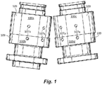
- Fig. 1 an illustrative view of embodiments of gear pump bearings in accordance with the disclosure is shown in Fig. 1 and is designated generally by reference characters 100a, 100b, 100c, and 100d. Other embodiments and/or aspects of this disclosure are shown in Figs. 2 and 3 .
- the systems and methods described herein can be used to improve gear pump efficiency, for example.
- a gear pump bearing 100a, 100b, 100c, 100d can include a body 101a, b, c, d sized and shaped to occupy a portion of a pump housing cavity 103 such that a clearance (a gap) is formed between the body 101a, b, c, d and a pump housing 105 as shown.
- the gear pump bearing 100a, b, c, d can also include at least one clearance consuming feature 107 extending from an outer surface 109 of the body 101a, b, c, d configured to reduce motion of the body 101a, b, c, d within the pump housing cavity 103.
- the at least one clearance consuming feature 107 can be or include at least one pin 107a disposed on or within the body 101a, b, c, d as shown in Figs. 1 and 2 .
- the at least one pin 107a can include a plurality of pins 107a disposed at different circumferential positions on the body 101a, b, c, d, also as shown in Figs. 1 and 2 .
- the plurality of pins 107a includes two pins 107a (e.g., as shown in Figs. 1 and 2 . Any other suitable number of pins 107a is contemplated herein.
- the plurality of pins 107a can be inserted into a respective pin hole defined in the body 101a, b, c, d.
- the plurality of pins 107a can be epoxied to the body 101a, b, c, d (e.g., in each pin hole), or attached to the body 101a, b, c, d in any other suitable manner.
- the pins 107a are disposed about 45 degrees apart, e.g., as shown. However, any other suitable relative position is contemplated herein.
- the at least one clearance consuming feature 107 can be or include at least one raised outer diameter extension 207a (e.g., integrally formed with the body 101a, b, c, d, or otherwise attached).
- the at least one raised outer diameter extension 207a can be a bump shape extending from the outer surface 109 of the body 101a, b, c, d. Any suitable number and/or shape of raised outer diameter extensions 207a are contemplated herein.
- the bearing 100a, b, c, d can include an inner aperture 111 defined in the body 101a, b, c, d for receiving a shaft of a gear for example.
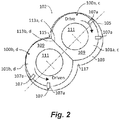
- the bearing 100a, c can include a flat 113a, c configured to mate with a flat 113b, d of mating gear bearing 100b, d within the pump housing cavity 103.
- the outer surface 109 can be partially circular having a first radius, and the pump housing 105 and/or the cavity 103 is partially circular having second radius.
- the first radius can be smaller than second radius which can create the clearance between the outer surface 109 and the housing 105.
- a gear pump 102 can include a pump housing 105 defining a pump housing cavity 103, an inlet 115, and an outlet 117.
- the gear pump 102 can include a plurality of gear bearings (e.g., 100a, b, c, d) disposed within the pump housing cavity 103, at least one of the gear bearings (e.g., all) including any suitable embodiment of a bearing (e.g., 100a, b, c, d) in accordance with this disclosure (e.g., as described above).
- the gear pump 102 can also include a plurality of gears (not shown) disposed within pump housing cavity 103.
- each gear can be rotatably mounted between and in contact with a pair (e.g., 100a and 100b or 100c and 100d) of the plurality of gear bearings.
- the gears and the gear bearings can be disposed within the pump housing 105 in a pumping relationship to cause pumping action between the inlet 115 and the outlet 117 when the gears are rotated.
- the gears can be sandwiched between two halves which can form hydraulic journal bearings.
- one or more pins or any other suitable features that extend from the outer surface 109 can consume outer diameter clearances and increase pump efficiency. Embodiments minimize bearing motion due to gear friction. Certain embodiments include one or more pins or other suitable features that occupy the clearance, and will only contact the housing in certain operations. In certain embodiments, the one or more pins or other suitable features can rest about 0.002 inches from the housing.
- a method can include drilling one or more pin holes in the body of the bearings, optionally adding an epoxy in the one or more pin holes, and then inserting a pin into each pin hole.
- the method can optionally include grinding down the pin to a desired size.
- Another method can include additively manufacturing or milling a gear bearing to include an outer diameter extension that is integral with the body.
- bearing halves can move away from each other at the mating flats, and/or away from the inlet wall. Embodiments prevent such motion without increasing the overall size of the bearing outer diameter.
- the cost of manufacturing and maintenance of bearings are reduced by eliminating a need for lap-to-fit clearances. Reduced manufacturing costs and improved volumetric efficiencies of gear pumps are realized by achieving tight internal clearances and small internal parasitic leakages.
- any numerical values disclosed herein can be exact values or can be values within a range. Further, any terms of approximation (e.g., “about”, “approximately”, “around”) used in this disclosure can mean the stated value within a range. For example, in certain embodiments, the range can be within (plus or minus) 20%, or within 10%, or within 5%, or within 2%, or within any other suitable percentage or number as appreciated by those having ordinary skill in the art (e.g., for known tolerance limits or error ranges).
Landscapes
- Engineering & Computer Science (AREA)
- General Engineering & Computer Science (AREA)
- Mechanical Engineering (AREA)
- Rotary Pumps (AREA)
- Details And Applications Of Rotary Liquid Pumps (AREA)
Abstract
Description
- The present disclosure relates to gear pumps, more specifically to bearings for gear pumps.
- Gear pumps require tight clearances around the bearings and gears within a housing bore in order to function efficiently. The traditional way of achieving tight clearances is to lap the bearings to fit the housing. This is a very expensive process. To reduce costs, certain modern pumps use controlled center distances and live with larger clearances and larger internal leakages, which causes reduced volumetric efficiencies.
- Such conventional methods and systems have generally been considered satisfactory for their intended purpose. However, there is still a need in the art for improved gear pump bearings. The present disclosure provides a solution for this need.
- A gear pump bearing can include a body sized and shaped to occupy a portion of a pump housing cavity such that a clearance is formed between the body and a pump housing. The gear pump bearing can also include at least one clearance consuming feature extending from an outer surface of the body configured to reduce motion of the body within the pump housing cavity.
- The at least one clearance consuming feature can be or include at least one pin disposed on or within the body. The at least one pin can include a plurality of pins disposed at different circumferential positions on the body.
- In certain embodiments, the plurality of pins includes two pins. The plurality of pins can be inserted into a respective pin hole defined in the body. In certain embodiments, the plurality of pins can be epoxied to the body (e.g., in each pin hole).
- In certain embodiments, the pins are disposed about 45 degrees apart. However, any other suitable relative position is contemplated herein.
- The at least one clearance consuming feature can be or include a raised outer diameter extension (e.g., integrally formed with the body, or otherwise attached). For example, the at least one clearance consuming feature can be a bump shape extending from the outer surface of the body. Any suitable number and/or shape of raised outer diameter extensions are contemplated herein.
- The bearing can include an inner aperture defined in the body for receiving a shaft of a gear. In certain embodiments, the bearing can include a flat configured to mate with a flat of mating gear bearing within the pump housing cavity. In certain embodiments, the outer surface can be partially circular having a first radius, wherein pump housing cavity is partially circular having second radius, wherein first radius is smaller than second radius.
- In accordance with at least one aspect of this disclosure, a gear pump can include a pump housing defining a pump housing cavity, an inlet, and an outlet. The gear pump can include a plurality of gear bearings disposed within the pump housing cavity, at least one of the gear bearings (e.g., all) including any suitable embodiment of a bearing in accordance with this disclosure (e.g., as described above). The gear pump can also include a plurality of gears disposed within pump housing cavity, each gear rotatably mounted between and in contact with a pair of the plurality of gear bearings. The gears and the gear bearings can be disposed within the pump housing in a pumping relationship to cause pumping action between the inlet and the outlet when the gears are rotated.
- These and other features of the systems and methods of the subject disclosure will become more readily apparent to those skilled in the art from the following detailed description taken in conjunction with the drawings.
- So that those skilled in the art to which the subject disclosure appertains will readily understand how to make and use the devices and methods of the subject disclosure without undue experimentation, embodiments thereof will be described in detail herein below with reference to certain figures, wherein:
-
Fig. 1 is a perspective view of embodiments of gear pump bearings in accordance with this disclosure, showing two pairs of bearings for use in a single gear pump. -
Fig. 2 is a cross-sectional schematic view of a gear pump in accordance with this disclosure, showing a pair of pump bearings, as shown inFig. 1 , mated at flats thereof within a gear pump cavity; and -
Fig. 3 is a cross-sectional schematic view of a gear pump in accordance with this disclosure, showing another embodiment of a pair of pump bearings mated at flats thereof within a gear pump cavity. - Reference will now be made to the drawings wherein like reference numerals identify similar structural features or aspects of the subject disclosure. For purposes of explanation and illustration, and not limitation, an illustrative view of embodiments of gear pump bearings in accordance with the disclosure is shown in
Fig. 1 and is designated generally byreference characters Figs. 2 and3 . The systems and methods described herein can be used to improve gear pump efficiency, for example. - Referring to
Figs. 1 and2 , a gear pump bearing 100a, 100b, 100c, 100d, can include abody 101a, b, c, d sized and shaped to occupy a portion of apump housing cavity 103 such that a clearance (a gap) is formed between thebody 101a, b, c, d and apump housing 105 as shown. The gear pump bearing 100a, b, c, d can also include at least oneclearance consuming feature 107 extending from anouter surface 109 of thebody 101a, b, c, d configured to reduce motion of thebody 101a, b, c, d within thepump housing cavity 103. - The at least one
clearance consuming feature 107 can be or include at least onepin 107a disposed on or within thebody 101a, b, c, d as shown inFigs. 1 and2 . The at least onepin 107a can include a plurality ofpins 107a disposed at different circumferential positions on thebody 101a, b, c, d, also as shown inFigs. 1 and2 . - In certain embodiments, the plurality of
pins 107a includes twopins 107a (e.g., as shown inFigs. 1 and2 . Any other suitable number ofpins 107a is contemplated herein. - The plurality of
pins 107a can be inserted into a respective pin hole defined in thebody 101a, b, c, d. In certain embodiments, the plurality ofpins 107a can be epoxied to thebody 101a, b, c, d (e.g., in each pin hole), or attached to thebody 101a, b, c, d in any other suitable manner. - In certain embodiments, the
pins 107a are disposed about 45 degrees apart, e.g., as shown. However, any other suitable relative position is contemplated herein. - Referring to
Fig. 3 , In certain embodiments, the at least oneclearance consuming feature 107 can be or include at least one raisedouter diameter extension 207a (e.g., integrally formed with thebody 101a, b, c, d, or otherwise attached). For example, the at least one raisedouter diameter extension 207a can be a bump shape extending from theouter surface 109 of thebody 101a, b, c, d. Any suitable number and/or shape of raisedouter diameter extensions 207a are contemplated herein. - Referring to
Fig. 2 , thebearing 100a, b, c, d can include aninner aperture 111 defined in thebody 101a, b, c, d for receiving a shaft of a gear for example. In certain embodiments, thebearing 100a, c can include a flat 113a, c configured to mate with a flat 113b, d of mating gear bearing 100b, d within thepump housing cavity 103. - In certain embodiments, the
outer surface 109 can be partially circular having a first radius, and thepump housing 105 and/or thecavity 103 is partially circular having second radius. The first radius can be smaller than second radius which can create the clearance between theouter surface 109 and thehousing 105. - In accordance with at least one aspect of this disclosure, a
gear pump 102 can include apump housing 105 defining apump housing cavity 103, aninlet 115, and anoutlet 117. Thegear pump 102 can include a plurality of gear bearings (e.g., 100a, b, c, d) disposed within thepump housing cavity 103, at least one of the gear bearings (e.g., all) including any suitable embodiment of a bearing (e.g., 100a, b, c, d) in accordance with this disclosure (e.g., as described above). - The
gear pump 102 can also include a plurality of gears (not shown) disposed withinpump housing cavity 103. As appreciated by those having ordinary skill in the art, each gear can be rotatably mounted between and in contact with a pair (e.g., 100a and 100b or 100c and 100d) of the plurality of gear bearings. The gears and the gear bearings can be disposed within thepump housing 105 in a pumping relationship to cause pumping action between theinlet 115 and theoutlet 117 when the gears are rotated. The gears can be sandwiched between two halves which can form hydraulic journal bearings. - In embodiments, one or more pins or any other suitable features that extend from the
outer surface 109 can consume outer diameter clearances and increase pump efficiency. Embodiments minimize bearing motion due to gear friction. Certain embodiments include one or more pins or other suitable features that occupy the clearance, and will only contact the housing in certain operations. In certain embodiments, the one or more pins or other suitable features can rest about 0.002 inches from the housing. - In certain embodiments, a method can include drilling one or more pin holes in the body of the bearings, optionally adding an epoxy in the one or more pin holes, and then inserting a pin into each pin hole. The method can optionally include grinding down the pin to a desired size. Another method can include additively manufacturing or milling a gear bearing to include an outer diameter extension that is integral with the body.
- In traditional pumps, bearing halves can move away from each other at the mating flats, and/or away from the inlet wall. Embodiments prevent such motion without increasing the overall size of the bearing outer diameter. By installing one or more pins or having other one or more other suitable features at a certain point or points, the cost of manufacturing and maintenance of bearings are reduced by eliminating a need for lap-to-fit clearances. Reduced manufacturing costs and improved volumetric efficiencies of gear pumps are realized by achieving tight internal clearances and small internal parasitic leakages.
- Any suitable combination(s) of any disclosed embodiments and/or any suitable portion(s) thereof are contemplated herein as appreciated by those having ordinary skill in the art.
- Those having ordinary skill in the art understand that any numerical values disclosed herein can be exact values or can be values within a range. Further, any terms of approximation (e.g., "about", "approximately", "around") used in this disclosure can mean the stated value within a range. For example, in certain embodiments, the range can be within (plus or minus) 20%, or within 10%, or within 5%, or within 2%, or within any other suitable percentage or number as appreciated by those having ordinary skill in the art (e.g., for known tolerance limits or error ranges).
- The embodiments of the present disclosure, as described above and shown in the drawings, provide for improvement in the art to which they pertain. While the subject disclosure includes reference to certain embodiments, those skilled in the art will readily appreciate that changes and/or modifications may be made thereto without departing from the scope of the subject disclosure.
Claims (12)
- A gear pump bearing (100a-100d), comprising:a body (101a-101d) sized and shaped to occupy a portion of a pump housing cavity (103) such that a clearance is formed between the body (101a-101d) and a pump housing (105); andat least one clearance consuming feature (107) extending from an outer surface of the body (101a - 101d) configured to reduce motion of the body (101a - 101d) within the pump housing cavity (103).
- The bearing of claim 1, wherein the at least one clearance consuming feature (107) is at least one pin (107a) disposed on or within the body (101a-101d).
- The bearing of claim 2, wherein the at least one pin (107a) includes a plurality of pins (107a) disposed at different circumferential positions on the body (101a-101d).
- The bearing of claim 3, wherein the plurality of pins (107a) includes two pins.
- The bearing of claim 4, wherein the plurality of pins (107a) are inserted into a respective pin hole defined in the body (101a-101d).
- The bearing of claim 5, wherein the plurality of pins (107a) are epoxied to the body (101a-101d).
- The bearing of claim 4, wherein the pins (107a) are disposed about 45 degrees apart.
- The bearing of claim 1, wherein the at least one clearance consuming feature (107) is a raised outer diameter extension.
- The bearing of any preceding claim1, further comprising an inner aperture defined in the body (101a-101d) for receiving a shaft of a gear.
- The bearing of any preceding claim, wherein the bearing includes a flat configured to mate with a flat of mating gear bearing within the pump housing cavity (103).
- The bearing of any preceding claim, wherein the outer surface is partially circular having a first radius, wherein pump housing cavity is partially circular having second radius, wherein first radius is smaller than second radius.
- A gear pump, comprising:a pump housing (105) defining a pump housing cavity (103), an inlet, and an outlet;a plurality of gear bearings disposed within the pump housing cavity (103), at least one of the gear bearings comprising: the gear pump of any preceding claim; further comprisinga plurality of gears disposed within pump housing cavity (103), each gear rotatably mounted between and in contact with a pair of the plurality of gear bearings, wherein the gears and the gear bearings are disposed within the pump housing (105) in a pumping relationship to cause pumping action between the inlet (115) and the outlet (117) when the gears are rotated.
Applications Claiming Priority (1)
| Application Number | Priority Date | Filing Date | Title |
|---|---|---|---|
| US16/041,621 US10858939B2 (en) | 2018-07-20 | 2018-07-20 | Gear pump bearings |
Publications (2)
| Publication Number | Publication Date |
|---|---|
| EP3597919A1 true EP3597919A1 (en) | 2020-01-22 |
| EP3597919B1 EP3597919B1 (en) | 2022-11-02 |
Family
ID=67438223
Family Applications (1)
| Application Number | Title | Priority Date | Filing Date |
|---|---|---|---|
| EP19187379.3A Active EP3597919B1 (en) | 2018-07-20 | 2019-07-19 | Gear pump bearings |
Country Status (2)
| Country | Link |
|---|---|
| US (1) | US10858939B2 (en) |
| EP (1) | EP3597919B1 (en) |
Families Citing this family (1)
| Publication number | Priority date | Publication date | Assignee | Title |
|---|---|---|---|---|
| US12247617B2 (en) | 2022-12-08 | 2025-03-11 | Hamilton Sundstrand Corporation | Cavitation resistant journal bearing |
Citations (2)
| Publication number | Priority date | Publication date | Assignee | Title |
|---|---|---|---|---|
| JP2002013485A (en) * | 2000-06-30 | 2002-01-18 | Tokico Ltd | Gear pump |
| EP2868925A1 (en) * | 2012-06-28 | 2015-05-06 | Hitachi, Ltd. | Gear pump |
Family Cites Families (8)
| Publication number | Priority date | Publication date | Assignee | Title |
|---|---|---|---|---|
| US3169040A (en) * | 1963-04-01 | 1965-02-09 | Bendix Corp | Bearing |
| US3427984A (en) * | 1967-05-25 | 1969-02-18 | Dennis P Slevin | Two-piece thrust plate for rotary pumps and motors |
| DE2610827A1 (en) * | 1976-03-15 | 1977-09-29 | Bosch Gmbh Robert | GEAR MACHINE (PUMP OR MOTOR) |
| DE2848994A1 (en) * | 1978-11-11 | 1980-05-22 | Bosch Gmbh Robert | GEAR MACHINE (PUMP OR HYDROMOTOR) |
| US4682938A (en) * | 1985-12-26 | 1987-07-28 | Sundstrand Corporation | Gear pump bearings |
| USH242H (en) * | 1986-07-08 | 1987-04-07 | The United States Of America As Represented By The Secretary Of The Navy | Method of keying outer bearing race to housing |
| ES2229228T3 (en) * | 1994-07-14 | 2005-04-16 | Casappa S.P.A. | GEAR PUMP. |
| US6390793B1 (en) * | 2001-02-13 | 2002-05-21 | Haldex Barnes Corporation | Rotary gear pump with fluid inlet size compensation |
-
2018
- 2018-07-20 US US16/041,621 patent/US10858939B2/en active Active
-
2019
- 2019-07-19 EP EP19187379.3A patent/EP3597919B1/en active Active
Patent Citations (2)
| Publication number | Priority date | Publication date | Assignee | Title |
|---|---|---|---|---|
| JP2002013485A (en) * | 2000-06-30 | 2002-01-18 | Tokico Ltd | Gear pump |
| EP2868925A1 (en) * | 2012-06-28 | 2015-05-06 | Hitachi, Ltd. | Gear pump |
Also Published As
| Publication number | Publication date |
|---|---|
| US20200024947A1 (en) | 2020-01-23 |
| EP3597919B1 (en) | 2022-11-02 |
| US10858939B2 (en) | 2020-12-08 |
Similar Documents
| Publication | Publication Date | Title |
|---|---|---|
| EP2831435B1 (en) | Gear pump with asymmetrical dual bearing | |
| DE102018207611A1 (en) | Rotor bearing system | |
| CN102996756B (en) | For the idler sheave assemblies of generator | |
| JP2024507034A (en) | Rotor assembly, compressor and air conditioner | |
| EP3597919B1 (en) | Gear pump bearings | |
| US4605363A (en) | Gear pump with pivoted bushings that can deflect | |
| CN114593053A (en) | Screw compressors and air conditioning systems | |
| EP0437919B1 (en) | Vane type positive displacement pump | |
| CN115163483A (en) | A hydraulic gear pump | |
| CN119778440A (en) | A friction transmission reducer | |
| US10584747B1 (en) | Fuel pump bearing with non-concentric inner diameters | |
| CN111237625B (en) | Anti-jamming high-efficiency transmission oil pump | |
| DE102022131277A1 (en) | Pump-motor unit with integrated cooling of an electronic component | |
| CN103115070A (en) | Self-aligning roller bearing retainer for brass entity, and forming method of retainer | |
| US20090238706A1 (en) | Self-Aligning Pump Rotor and Methods | |
| US9383013B2 (en) | Piston with replaceable and/or adjustable surfaces | |
| CN114396427A (en) | Self-lubricating bearing and preparation method thereof | |
| DE102016118627A1 (en) | Pump for liquid fluids with floating rotor bearings | |
| CN212273647U (en) | Anti-clamping stagnation efficient transmission oil pump | |
| CN114992236A (en) | A concave spherical tapered roller bearing | |
| CN106763152A (en) | A kind of turbocharger dynamically limits oily formula thrust bearing | |
| CN222067057U (en) | A double bearing rotor pump | |
| DE102015108923B3 (en) | Electrically driven liquid displacement pump | |
| CN223190675U (en) | A bearing box for the non-drive end of a multi-stage centrifugal pump | |
| CN220956032U (en) | Sealing structure between multistage rotary plate pump stages |
Legal Events
| Date | Code | Title | Description |
|---|---|---|---|
| PUAI | Public reference made under article 153(3) epc to a published international application that has entered the european phase |
Free format text: ORIGINAL CODE: 0009012 |
|
| STAA | Information on the status of an ep patent application or granted ep patent |
Free format text: STATUS: THE APPLICATION HAS BEEN PUBLISHED |
|
| AK | Designated contracting states |
Kind code of ref document: A1 Designated state(s): AL AT BE BG CH CY CZ DE DK EE ES FI FR GB GR HR HU IE IS IT LI LT LU LV MC MK MT NL NO PL PT RO RS SE SI SK SM TR |
|
| AX | Request for extension of the european patent |
Extension state: BA ME |
|
| STAA | Information on the status of an ep patent application or granted ep patent |
Free format text: STATUS: REQUEST FOR EXAMINATION WAS MADE |
|
| 17P | Request for examination filed |
Effective date: 20200722 |
|
| RBV | Designated contracting states (corrected) |
Designated state(s): AL AT BE BG CH CY CZ DE DK EE ES FI FR GB GR HR HU IE IS IT LI LT LU LV MC MK MT NL NO PL PT RO RS SE SI SK SM TR |
|
| GRAP | Despatch of communication of intention to grant a patent |
Free format text: ORIGINAL CODE: EPIDOSNIGR1 |
|
| STAA | Information on the status of an ep patent application or granted ep patent |
Free format text: STATUS: GRANT OF PATENT IS INTENDED |
|
| INTG | Intention to grant announced |
Effective date: 20220524 |
|
| GRAS | Grant fee paid |
Free format text: ORIGINAL CODE: EPIDOSNIGR3 |
|
| GRAA | (expected) grant |
Free format text: ORIGINAL CODE: 0009210 |
|
| STAA | Information on the status of an ep patent application or granted ep patent |
Free format text: STATUS: THE PATENT HAS BEEN GRANTED |
|
| AK | Designated contracting states |
Kind code of ref document: B1 Designated state(s): AL AT BE BG CH CY CZ DE DK EE ES FI FR GB GR HR HU IE IS IT LI LT LU LV MC MK MT NL NO PL PT RO RS SE SI SK SM TR |
|
| REG | Reference to a national code |
Ref country code: GB Ref legal event code: FG4D |
|
| REG | Reference to a national code |
Ref country code: CH Ref legal event code: EP Ref country code: AT Ref legal event code: REF Ref document number: 1528934 Country of ref document: AT Kind code of ref document: T Effective date: 20221115 |
|
| REG | Reference to a national code |
Ref country code: DE Ref legal event code: R096 Ref document number: 602019021332 Country of ref document: DE |
|
| REG | Reference to a national code |
Ref country code: IE Ref legal event code: FG4D |
|
| REG | Reference to a national code |
Ref country code: LT Ref legal event code: MG9D |
|
| REG | Reference to a national code |
Ref country code: NL Ref legal event code: MP Effective date: 20221102 |
|
| REG | Reference to a national code |
Ref country code: AT Ref legal event code: MK05 Ref document number: 1528934 Country of ref document: AT Kind code of ref document: T Effective date: 20221102 |
|
| PG25 | Lapsed in a contracting state [announced via postgrant information from national office to epo] |
Ref country code: SE Free format text: LAPSE BECAUSE OF FAILURE TO SUBMIT A TRANSLATION OF THE DESCRIPTION OR TO PAY THE FEE WITHIN THE PRESCRIBED TIME-LIMIT Effective date: 20221102 Ref country code: PT Free format text: LAPSE BECAUSE OF FAILURE TO SUBMIT A TRANSLATION OF THE DESCRIPTION OR TO PAY THE FEE WITHIN THE PRESCRIBED TIME-LIMIT Effective date: 20230302 Ref country code: NO Free format text: LAPSE BECAUSE OF FAILURE TO SUBMIT A TRANSLATION OF THE DESCRIPTION OR TO PAY THE FEE WITHIN THE PRESCRIBED TIME-LIMIT Effective date: 20230202 Ref country code: LT Free format text: LAPSE BECAUSE OF FAILURE TO SUBMIT A TRANSLATION OF THE DESCRIPTION OR TO PAY THE FEE WITHIN THE PRESCRIBED TIME-LIMIT Effective date: 20221102 Ref country code: FI Free format text: LAPSE BECAUSE OF FAILURE TO SUBMIT A TRANSLATION OF THE DESCRIPTION OR TO PAY THE FEE WITHIN THE PRESCRIBED TIME-LIMIT Effective date: 20221102 Ref country code: ES Free format text: LAPSE BECAUSE OF FAILURE TO SUBMIT A TRANSLATION OF THE DESCRIPTION OR TO PAY THE FEE WITHIN THE PRESCRIBED TIME-LIMIT Effective date: 20221102 Ref country code: AT Free format text: LAPSE BECAUSE OF FAILURE TO SUBMIT A TRANSLATION OF THE DESCRIPTION OR TO PAY THE FEE WITHIN THE PRESCRIBED TIME-LIMIT Effective date: 20221102 |
|
| PG25 | Lapsed in a contracting state [announced via postgrant information from national office to epo] |
Ref country code: RS Free format text: LAPSE BECAUSE OF FAILURE TO SUBMIT A TRANSLATION OF THE DESCRIPTION OR TO PAY THE FEE WITHIN THE PRESCRIBED TIME-LIMIT Effective date: 20221102 Ref country code: PL Free format text: LAPSE BECAUSE OF FAILURE TO SUBMIT A TRANSLATION OF THE DESCRIPTION OR TO PAY THE FEE WITHIN THE PRESCRIBED TIME-LIMIT Effective date: 20221102 Ref country code: LV Free format text: LAPSE BECAUSE OF FAILURE TO SUBMIT A TRANSLATION OF THE DESCRIPTION OR TO PAY THE FEE WITHIN THE PRESCRIBED TIME-LIMIT Effective date: 20221102 Ref country code: IS Free format text: LAPSE BECAUSE OF FAILURE TO SUBMIT A TRANSLATION OF THE DESCRIPTION OR TO PAY THE FEE WITHIN THE PRESCRIBED TIME-LIMIT Effective date: 20230302 Ref country code: HR Free format text: LAPSE BECAUSE OF FAILURE TO SUBMIT A TRANSLATION OF THE DESCRIPTION OR TO PAY THE FEE WITHIN THE PRESCRIBED TIME-LIMIT Effective date: 20221102 Ref country code: GR Free format text: LAPSE BECAUSE OF FAILURE TO SUBMIT A TRANSLATION OF THE DESCRIPTION OR TO PAY THE FEE WITHIN THE PRESCRIBED TIME-LIMIT Effective date: 20230203 |
|
| P01 | Opt-out of the competence of the unified patent court (upc) registered |
Effective date: 20230522 |
|
| PG25 | Lapsed in a contracting state [announced via postgrant information from national office to epo] |
Ref country code: NL Free format text: LAPSE BECAUSE OF FAILURE TO SUBMIT A TRANSLATION OF THE DESCRIPTION OR TO PAY THE FEE WITHIN THE PRESCRIBED TIME-LIMIT Effective date: 20221102 |
|
| PG25 | Lapsed in a contracting state [announced via postgrant information from national office to epo] |
Ref country code: SM Free format text: LAPSE BECAUSE OF FAILURE TO SUBMIT A TRANSLATION OF THE DESCRIPTION OR TO PAY THE FEE WITHIN THE PRESCRIBED TIME-LIMIT Effective date: 20221102 Ref country code: RO Free format text: LAPSE BECAUSE OF FAILURE TO SUBMIT A TRANSLATION OF THE DESCRIPTION OR TO PAY THE FEE WITHIN THE PRESCRIBED TIME-LIMIT Effective date: 20221102 Ref country code: EE Free format text: LAPSE BECAUSE OF FAILURE TO SUBMIT A TRANSLATION OF THE DESCRIPTION OR TO PAY THE FEE WITHIN THE PRESCRIBED TIME-LIMIT Effective date: 20221102 Ref country code: DK Free format text: LAPSE BECAUSE OF FAILURE TO SUBMIT A TRANSLATION OF THE DESCRIPTION OR TO PAY THE FEE WITHIN THE PRESCRIBED TIME-LIMIT Effective date: 20221102 Ref country code: CZ Free format text: LAPSE BECAUSE OF FAILURE TO SUBMIT A TRANSLATION OF THE DESCRIPTION OR TO PAY THE FEE WITHIN THE PRESCRIBED TIME-LIMIT Effective date: 20221102 |
|
| REG | Reference to a national code |
Ref country code: DE Ref legal event code: R097 Ref document number: 602019021332 Country of ref document: DE |
|
| PG25 | Lapsed in a contracting state [announced via postgrant information from national office to epo] |
Ref country code: SK Free format text: LAPSE BECAUSE OF FAILURE TO SUBMIT A TRANSLATION OF THE DESCRIPTION OR TO PAY THE FEE WITHIN THE PRESCRIBED TIME-LIMIT Effective date: 20221102 Ref country code: AL Free format text: LAPSE BECAUSE OF FAILURE TO SUBMIT A TRANSLATION OF THE DESCRIPTION OR TO PAY THE FEE WITHIN THE PRESCRIBED TIME-LIMIT Effective date: 20221102 |
|
| PLBE | No opposition filed within time limit |
Free format text: ORIGINAL CODE: 0009261 |
|
| STAA | Information on the status of an ep patent application or granted ep patent |
Free format text: STATUS: NO OPPOSITION FILED WITHIN TIME LIMIT |
|
| 26N | No opposition filed |
Effective date: 20230803 |
|
| PG25 | Lapsed in a contracting state [announced via postgrant information from national office to epo] |
Ref country code: SI Free format text: LAPSE BECAUSE OF FAILURE TO SUBMIT A TRANSLATION OF THE DESCRIPTION OR TO PAY THE FEE WITHIN THE PRESCRIBED TIME-LIMIT Effective date: 20221102 |
|
| PG25 | Lapsed in a contracting state [announced via postgrant information from national office to epo] |
Ref country code: MC Free format text: LAPSE BECAUSE OF FAILURE TO SUBMIT A TRANSLATION OF THE DESCRIPTION OR TO PAY THE FEE WITHIN THE PRESCRIBED TIME-LIMIT Effective date: 20221102 |
|
| PG25 | Lapsed in a contracting state [announced via postgrant information from national office to epo] |
Ref country code: MC Free format text: LAPSE BECAUSE OF FAILURE TO SUBMIT A TRANSLATION OF THE DESCRIPTION OR TO PAY THE FEE WITHIN THE PRESCRIBED TIME-LIMIT Effective date: 20221102 |
|
| REG | Reference to a national code |
Ref country code: CH Ref legal event code: PL |
|
| REG | Reference to a national code |
Ref country code: BE Ref legal event code: MM Effective date: 20230731 |
|
| PG25 | Lapsed in a contracting state [announced via postgrant information from national office to epo] |
Ref country code: LU Free format text: LAPSE BECAUSE OF NON-PAYMENT OF DUE FEES Effective date: 20230719 |
|
| PG25 | Lapsed in a contracting state [announced via postgrant information from national office to epo] |
Ref country code: LU Free format text: LAPSE BECAUSE OF NON-PAYMENT OF DUE FEES Effective date: 20230719 |
|
| REG | Reference to a national code |
Ref country code: IE Ref legal event code: MM4A |
|
| PG25 | Lapsed in a contracting state [announced via postgrant information from national office to epo] |
Ref country code: CH Free format text: LAPSE BECAUSE OF NON-PAYMENT OF DUE FEES Effective date: 20230731 |
|
| PG25 | Lapsed in a contracting state [announced via postgrant information from national office to epo] |
Ref country code: IT Free format text: LAPSE BECAUSE OF FAILURE TO SUBMIT A TRANSLATION OF THE DESCRIPTION OR TO PAY THE FEE WITHIN THE PRESCRIBED TIME-LIMIT Effective date: 20221102 Ref country code: BE Free format text: LAPSE BECAUSE OF NON-PAYMENT OF DUE FEES Effective date: 20230731 |
|
| PG25 | Lapsed in a contracting state [announced via postgrant information from national office to epo] |
Ref country code: IE Free format text: LAPSE BECAUSE OF NON-PAYMENT OF DUE FEES Effective date: 20230719 |
|
| PG25 | Lapsed in a contracting state [announced via postgrant information from national office to epo] |
Ref country code: IE Free format text: LAPSE BECAUSE OF NON-PAYMENT OF DUE FEES Effective date: 20230719 |
|
| PG25 | Lapsed in a contracting state [announced via postgrant information from national office to epo] |
Ref country code: BG Free format text: LAPSE BECAUSE OF FAILURE TO SUBMIT A TRANSLATION OF THE DESCRIPTION OR TO PAY THE FEE WITHIN THE PRESCRIBED TIME-LIMIT Effective date: 20221102 |
|
| PG25 | Lapsed in a contracting state [announced via postgrant information from national office to epo] |
Ref country code: BG Free format text: LAPSE BECAUSE OF FAILURE TO SUBMIT A TRANSLATION OF THE DESCRIPTION OR TO PAY THE FEE WITHIN THE PRESCRIBED TIME-LIMIT Effective date: 20221102 |
|
| PGFP | Annual fee paid to national office [announced via postgrant information from national office to epo] |
Ref country code: GB Payment date: 20250619 Year of fee payment: 7 |
|
| PGFP | Annual fee paid to national office [announced via postgrant information from national office to epo] |
Ref country code: FR Payment date: 20250620 Year of fee payment: 7 |
|
| PG25 | Lapsed in a contracting state [announced via postgrant information from national office to epo] |
Ref country code: CY Free format text: LAPSE BECAUSE OF FAILURE TO SUBMIT A TRANSLATION OF THE DESCRIPTION OR TO PAY THE FEE WITHIN THE PRESCRIBED TIME-LIMIT; INVALID AB INITIO Effective date: 20190719 |
|
| PG25 | Lapsed in a contracting state [announced via postgrant information from national office to epo] |
Ref country code: HU Free format text: LAPSE BECAUSE OF FAILURE TO SUBMIT A TRANSLATION OF THE DESCRIPTION OR TO PAY THE FEE WITHIN THE PRESCRIBED TIME-LIMIT; INVALID AB INITIO Effective date: 20190719 |
|
| PGFP | Annual fee paid to national office [announced via postgrant information from national office to epo] |
Ref country code: DE Payment date: 20250620 Year of fee payment: 7 |
|
| PG25 | Lapsed in a contracting state [announced via postgrant information from national office to epo] |
Ref country code: TR Free format text: LAPSE BECAUSE OF FAILURE TO SUBMIT A TRANSLATION OF THE DESCRIPTION OR TO PAY THE FEE WITHIN THE PRESCRIBED TIME-LIMIT Effective date: 20221102 |